Champion Power Equipment 100199 Operators Manual
2015-08-26
: Champion-Power-Equipment Champion-Power-Equipment--100199-Operators-Manual-802563 champion-power-equipment--100199-operators-manual-802563 champion-power-equipment pdf
Open the PDF directly: View PDF ![]() .
.
Page Count: 40
REV 100199-20150409

CALIFORNIA PROPOSITION 65 WARNING
Certain components in this product and its related accessories contain chemicals known to the state of California
to cause cancer, birth defects or other reproductive harm. Wash hands after handling.
CALIFORNIA PROPOSITION 65 WARNING
The engine exhaust from this product contains chemicals known to the state of California to cause cancer, birth
defects or other reproductive harm.
DISCLAIMERS
All information, illustrations and specications in this manual are based on the latest information available at
the time of publishing. The illustrations used in this manual are intended as representative reference views only.
Products are under a continuous improvement policy. Thus, information, illustrations and/or specications to explain
and/or exemplify a product, service or maintenance improvement may be changed at any time without notice.
ALL RIGHTS RESERVED
No part of this publication may be reproduced or used in any form by any means – graphic, electronic or
mechanical, including photocopying, recording, taping or information storage and retrieval systems – without the
written permission of Champion Power Equipment (CPE).
Have questions or need assistance?
Do not return this product to the store!
WE ARE HERE TO HELP!
Visit our website:
www.championpowerequipment.com
for more info:
s Product Info & Updates
s Frequently Asked Questions
s Tech Bulletins
s Product Registration
– or –
Call our Customer Care Team Toll-Free at:
1-877-338-0999
*We are always working to improve our products. Therefore, the enclosed product may differ slightly from the image on the cover.
This manual must be used with Champion Power Equipment (CPE) manuals:
t Installation Manual, Part No. 101049
t Transfer Switch Manual, Part No. 101111
It is also recommended to refer to the reference materials list on
page 16 of the Installation Manual.

3
Model 100199
CONTENTS
© 2015 Champion Power Equipment Part No. 101048
CONTENTS
INTRODUCTION ........................... 4
Home standby generator ....................4
SAFETY ................................. 5
Safety Symbol Denitions ...................5
Installation Hazards. . . . . . . . . . . . . . . . . . . . . . . . 6
Before Starting ...........................7
Operating Hazards ........................7
Accidental Starting ........................8
Carbon Monoxide Hazards ...................8
Electrical Shock Hazards ....................9
Fire/Explosion Hazards . . . . . . . . . . . . . . . . . . . . . 9
Burn Hazards ...........................10
Entanglement Hazards . . . . . . . . . . . . . . . . . . . . 10
Battery Hazards .........................10
Safety Labels ...........................10
Safety, Serial/Model, Nameplate Label Locations . . . 11
Safety Labels on Unit . . . . . . . . . . . . . . . . . . . . . . . 12
GENERAL INFORMATION ...................13
Component Identication – 8.5 kW Generator. . . . 13
Component Identication – Engine ............14
Control Panel ..........................14
Main Circuit Breaker. . . . . . . . . . . . . . . . . . . . . . . . 14
Exercise Switch ........................... 14
Set Exercise Time .......................... 15
Hour Meter .............................. 15
Engine Control Module ...................... 15
Reset Fault Code(s) . . . . . . . . . . . . . . . . . . . . . . . . 15
ATS Control Module ........................ 16
Battery Charger .........................17
Emission Requirements ....................17
Specications ...........................18
Fuel System ............................19
Battery Requirements .....................19
Battery Charging ........................19
Model and Serial Number . . . . . . . . . . . . . . . . . . 19
OPERATION .............................20
Enclosure and Access .....................20
Pre-Start Checklist .......................20
Turning Off the Generator ..................20
MAINTENANCE ...........................21
Scheduled Maintenance Chart ...............21
Engine Oil .............................21
Engine Oil Requirements . . . . . . . . . . . . . . . . . . . . 21
Checking the Engine Oil Level ................. 21
Changing the Engine Oil Level ................. 22
Inspect and Clean Engine Air Cleaner ..........23
Spark Plug .............................23
Battery Maintenance ......................24
Corrosion Protection ......................24
Maintenance After Submersion . . . . . . . . . . . . . . 24
Storage ...............................24
Return to Service after Storage ................ 25
Engine Parts Diagram ....................... 26
Engine Parts List .......................... 27
Enclosure and Assemblies Diagram ............. 28
Enclosure and Assemblies Parts List . . . . . . . . . . . . 29
Alternator and Exhaust System Diagram . . . . . . . . . 30
Alternator and Exhaust System Parts List ......... 31
Control Panel Diagram . . . . . . . . . . . . . . . . . . . . . . 32
Control Panel Parts List . . . . . . . . . . . . . . . . . . . . . 33
Wiring Diagram ........................... 34
TROUBLESHOOTING .......................35

Model 100199
INTRODUCTION
4Part No. 101048
Congratulations on your purchase of a Champion Power
Equipment (CPE) home standby generator. This generator is
designed and engineered in the USA to exacting standards of the
North American market. This engine-powered generator meets
all Environmental Protection Agency (EPA) Phase 3 requirements
and is approved by CETLUS as tested to UL2200 and CSA22.2 No.
100 in both the USA and Canada.
With proper use and maintenance, this generator will provide
years of satisfying service.
The Champion Staff,
Champion Power Equipment
12039 Smith Ave.
Santa Fe Springs, CA 90670
Toll-free: 1-877-338-0999
Mon-Fri 8:30 AM – 5:00 PM (PST/PDT)
www.championpowerequipment.com
HOME STANDBY GENERATOR
This home standby generator is intended exclusively for outdoor
installation. This generator will operate using either liquied
petroleum gas (LPG) or natural gas (NG).
This generator is designed to supply typical home load such as:
t Induction motors – sump pumps, refrigerators, air
conditioners, furnaces
t Electronic items – televisions, computers
t Household lighting
t Microwaves
t This generator is not intended for use in critical life
support applications.
Proper sizing of the generator is required to ensure proper
operation of appliances. Some appliances require additional
wattage to start and must be considered.
5
Model 100199
SAFETY
© 2015 Champion Power Equipment Part No. 101048
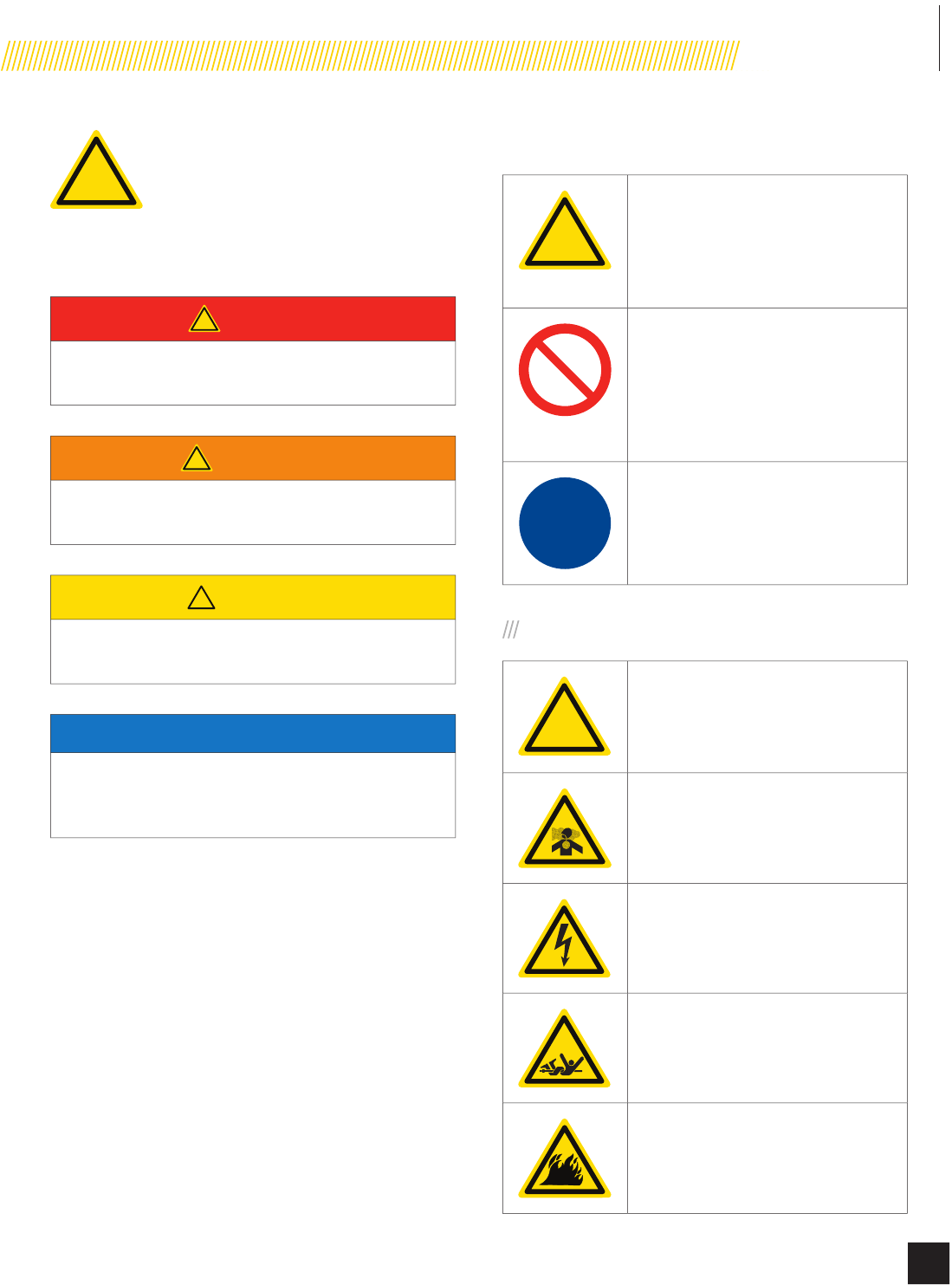
!
This is the safety alert symbol. It is used to alert
you to potential physical injury hazards. Obey all
safety messages that follow this symbol to avoid
possible injury or death.
The words DANGER, WARNING, CAUTION and NOTICE are used
throughout this manual to highlight important information.
! DANGER
Indicates a hazardous situation that, if not avoided, will
result in death or serious injury.
! WARNING
Indicates a hazardous situation that, if not avoided,
could result in death or serious injury.
! CAUTION
Indicates a hazardous situation that, if not avoided,
could result in minor or moderate injury.
NOTICE
Indicates a situation that can cause damage to the
equipment, personal property and/or the environment, or
cause the equipment to operate improperly.
OTE:NIndicates a procedure, practice or condition that
should be followed in order for the generator to
function in the manner intended.
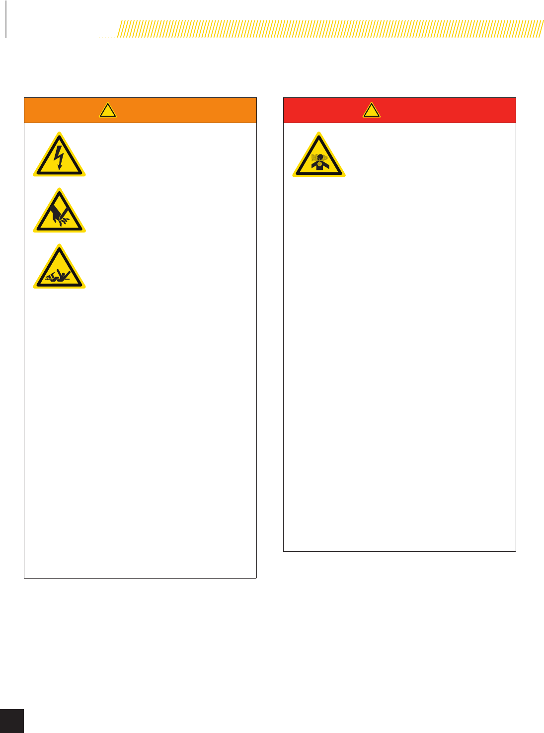
SAFETY SYMBOL DEFINITIONS
!
Black hazard pictorial on yellow
equilateral triangle enclosed by black
triangular band
Warns that hazard exists and describes
its nature and/or consequences
Black hazard pictorial on white circle
enclosed by red circular band with red
diagonal bar
Depicts action NOT to be taken or
action to be stopped in order to avoid
hazard
White hazard pictorial on blue circle
Depicts action to be taken in order to
avoid hazard
WARNINGS
!Safety alert symbol
Asphyxiation hazard
Electrical shock hazard
Entanglement hazard
Fire hazard
6
Model 100199
SAFETY
Part No. 101048
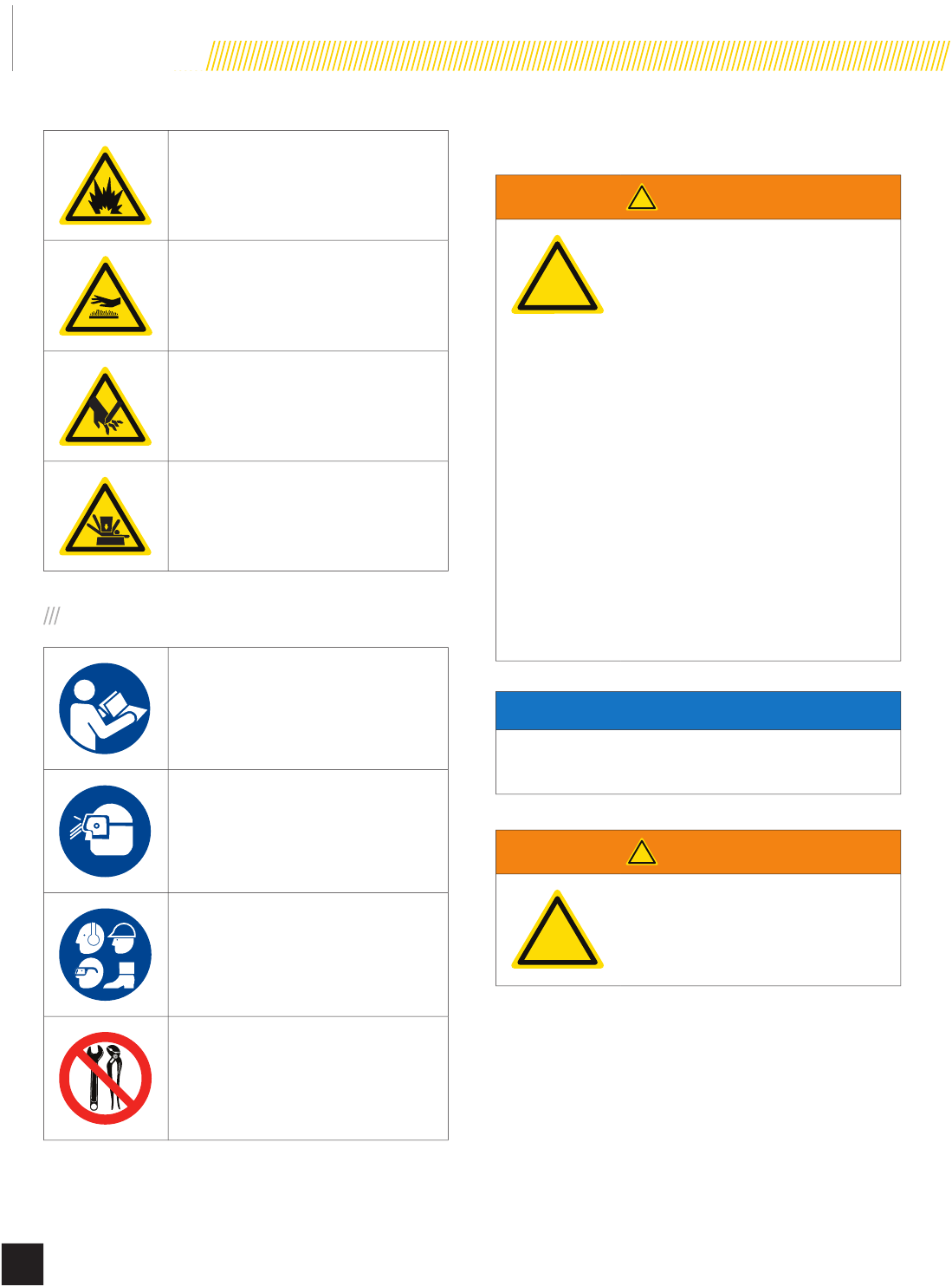
Explosion hazard
Burn hazard
Sever hazard (rotating blade)
Crush hazard (top)
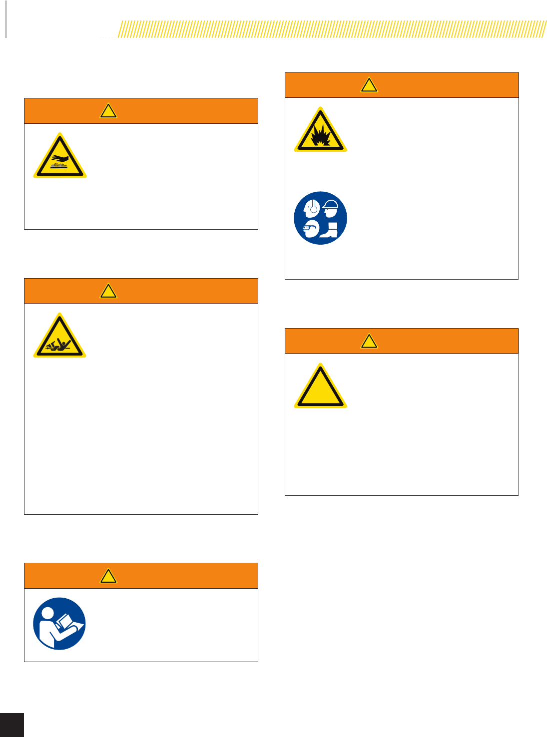
MANDATORY ACTIONS
Read manufacturer’s instructions
Wear eye protection
Wear personal protective equipment
Do not leave tools in the area
INSTALLATION HAZARDS
! WARNING
!
Have only a qualied electrician
or installation technician who is
familiar with applicable codes,
standards and regulations install
and service the generator.
ALWAYS comply with local, state
and national electrical and building
codes when installing the generator.
NEVER alter the recommended
installation in a way that would
render the unit noncompliant with
these codes.
ALWAYS comply with regulations
that Occupational Safety and
Health Administration (OSHA) has
established.
ENSURE the generator is installed
following the manufacturer’s
instructions.
NOTICE
Before welding components on the generator, contact CPE
for recommended welding instructions.
! WARNING
!
Not intended for use in critical life
support applications.
7
Model 100199
SAFETY
© 2015 Champion Power Equipment Part No. 101048
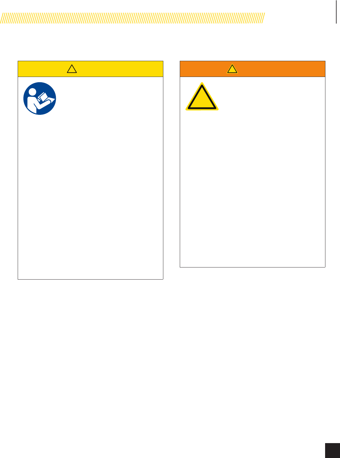
BEFORE STARTING
! CAUTION
Before starting, operating and
maintaining this generator, be sure
to read and understand the content
and safety messages in this manual.
The operator is responsible for safe
operation and maintenance of the
generator. Be sure all potential users
of the generator also understand
these instructions. If any portion
of this manual is not understood,
contact your dealer for assistance
before operating the generator.
The operator is responsible for
performing all safety checks, making
sure all maintenance is properly
performed and making sure the
generator is periodically checked by
the dealer.
Inspect the generator regularly.
Contact your dealer if repairs are
needed.
NEVER climb or step on any part or
components of the generator. Doing
so may result in injury and cause
leaking fuel and exhaust.
OPERATING HAZARDS
! WARNING
!
ALWAYS operate the generator
following the manufacturer’s
instructions. Operating the generator
imprudently, neglecting maintenance
or being careless can result in injury
or possible death.
DO NOT allow children or unqualied
persons to operate or service the
generator.
NEVER operate the generator
with the covers open. Operate the
generator only with the covers
closed and secured in place. NEVER
leave the covers unlocked.
Remain alert at all times when
working on the generator. NEVER
work on the generator when
physically or mentally fatigued.
Never operate the generator while
under the inuence of alcohol
or drugs. Their effects on vision
and judgment make operating a
generator dangerous.
8
Model 100199
SAFETY
Part No. 101048
ACCIDENTAL STARTING
! WARNING
ALWAYS prevent the generator from
starting while the covers are open.
The generator may crank and start
at any time without notice. Follow
these steps in order:
1. Turn the exercise switch to
the OFF position.
2. Switch the main circuit
breaker to the OFF position.
3. Turn the ATS control module
to the OFF position.
4. Turn the engine control
module switch to the OFF
position.
5. Disconnect the NEGATIVE, NEG
or (-) battery cable rst, and
then remove the POSITIVE,
POS or (+) battery cable.
To return the generator to service,
follow these steps in order:
1. Connect the POSITIVE, POS
or (+) battery cable rst, and
then connect the NEGATIVE,
NEG or (-) battery cable.
2. Turn the engine control
module switch to the ATS
position.
3. Turn the ATS control module
switch to the AUTO position.
4. Switch the main circuit
breaker to the ON position.
5. Turn the exercise switch to
the ON position.
CARBON MONOXIDE HAZARDS
! DANGER
Generator exhaust contains carbon
monoxide, a colorless, odorless,
poisonous gas. Breathing carbon
monoxide will cause nausea,
dizziness, fainting or death. If you
start to feel dizzy or weak, get to
fresh air immediately.
t The generator must be installed
and operated outdoors only.
NEVER install the generator where
exhaust fumes could seep inside
or be drawn into a potentially
occupied building through
windows, air intake vents or other
openings.
t Avoid breathing exhaust fumes
when near an operating generator.
t NEVER alter or add to the exhaust
system or do anything that might
render the system unsafe or in
noncompliance with applicable
codes, standards, laws and
regulations.
t Install a battery-operated carbon
monoxide detector on each
level of any building adjacent
to the generator following the
manufacturer’s instructions.
t NEVER permit even partial
blockage of engine cooling
ventilation air. Doing so can
seriously affect safe operation of
the generator.
Carbon monoxide poisoning symptoms include but are not
limited to the following:
t Light-headedness, dizziness
t Physical fatigue, weakness in joints and muscles
t Sleepiness, mental fatigue, inability to concentrate or
speak clearly, blurred vision
t Stomachache, vomiting, nausea
9
Model 100199
SAFETY
© 2015 Champion Power Equipment Part No. 101048
Carbon monoxide poisoning is possible if someone is
experiencing any of these symptoms. Seek fresh air immediately.
DO NOT sit, lie down or fall asleep. Alert others to the possibility
of carbon monoxide poisoning. If the affected person does
not improve within minutes of breathing fresh air, call 911
immediately.
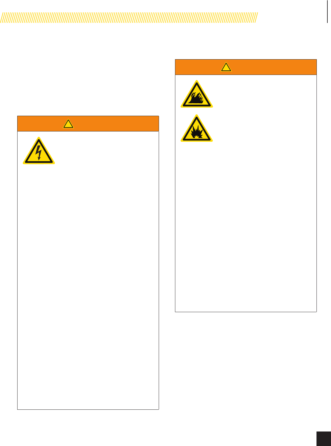
ELECTRICAL SHOCK HAZARDS
! WARNING
Use extreme caution when near
the generator while it is operating.
The generator produces dangerous
voltage.
t Avoid contact with bare wires,
terminals and connections while
the generator is operating.
t ALWAYS stand on an insulated dry
surface to reduce shock hazard
if work must be done on an
operating generator.
t NEVER wear jewelry that can
conduct electricity when working
on the generator.
t NEVER handle any kind of
electrical device while hands or
feet are wet, while standing in
water or while barefoot.
t Proper earth grounding of the
frame and external electrical
conductive components is
required by the National Electrical
Code (NEC). State and local codes
for proper grounding may also
apply.
t Avoid direct contact with an
electric shock victim. Immediately
shut down the source of electrical
power. If this is not possible,
attempt to free the victim from
the live conductor using a
nonconducting item such as a
dry board or rope. If the victim is
unconscious, apply rst aid and
call 911 immediately.
FIRE/EXPLOSION HAZARDS
! WARNING
NG and LPG are extremely explosive.
t NEVER allow any ames or smoke
near the fuel system.
t Wipe up any oil spills immediately.
t NEVER allow any combustible
materials to be near the generator
or to be left in the generator
compartment.
t ALWAYS keep the surrounding
area near the generator clean and
free of debris.
t Be sure to properly purge the fuel
lines and leak-test according to
applicable codes before placing
the generator in service.
t Be sure to regularly inspect the
fuel system for leaks. NEVER
operate the generator if a fuel leak
is present.
t Install a re extinguisher near
the generator. Keep it properly
charged and be familiar with
its use. An ABC rated National
Fire Protection extinguisher is
appropriate for use on standby
electric systems. Contact your
local re department with any
questions concerning the re
extinguisher.
10
Model 100199
SAFETY
Part No. 101048
BURN HAZARDS
! WARNING
ALWAYS allow hot surfaces to cool to
the touch. Running engines produce
heat. Severe burns can occur on
contact.
t DO NOT touch hot surfaces.
t Avoid contact with hot exhaust
components and gases.
ENTANGLEMENT HAZARDS
! WARNING
Use extreme caution when near
rotating parts. Rotating parts can
entangle hands, feet, hair, clothing
and/or accessories. Traumatic
amputation or severe laceration can
result.
t Keep hands and feet away from
rotating parts.
t Tie up long hair and remove
jewelry.
t Operate equipment with guards in
place.
t DO NOT wear loose-tting
clothing, dangling drawstrings or
items that could become caught.
BATTERY HAZARDS
! WARNING
Always read and comply with
the battery manufacturer’s
recommendations for procedures
concerning proper battery use and
maintenance.
! WARNING
Batteries contain sulfuric acid and
generate explosive mixtures of
hydrogen and oxygen gases. Keep
any device that may cause sparks
or ames away from the battery to
prevent explosion.
Always wear protective glasses
or goggles and protective clothing
when working with batteries.
You must follow the battery
manufacturer’s instructions on
safety, maintenance and installation
procedures.
SAFETY LABELS
! WARNING
!
All safety labels must be legible to
alert personnel of safety hazards.
t Replace any illegible or missing
label immediately. Missing safety
labels must be replaced in their
original position before the
generator is operated.
t DO NOT operate the generator if
there are missing or badly worn
safety labels.
11
Model 100199
SAFETY
© 2015 Champion Power Equipment Part No. 101048
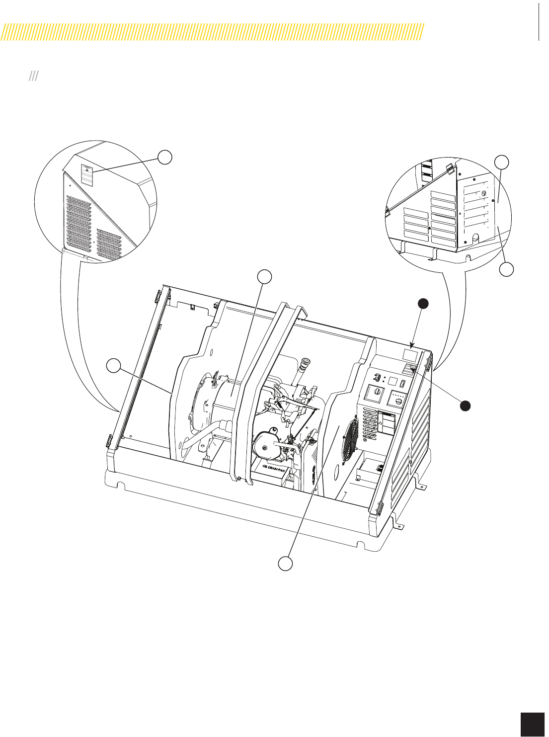
SAFETY, SERIAL/MODEL, NAMEPLATE LABEL LOCATIONS
The safety labels have specic placement and must be replaced if they are unreadable, damaged or missing.
!
6
2
1
4
5
3
A) Serial number locaon
B) Nameplate
A
B
12
Model 100199
SAFETY
Part No. 101048
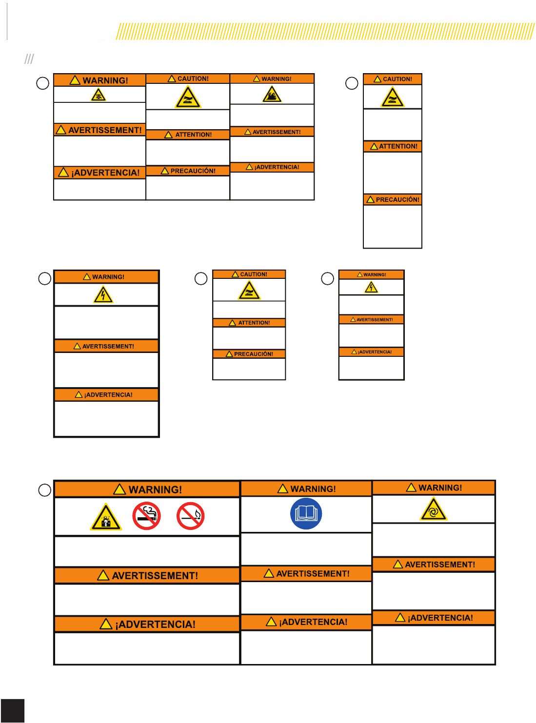
100788
Read Operator’s Manual Read,
understand and follow all safety
messages in Installation and Operator’s
manuals.
Lisez le manuel d’utilisation Lisez,
comprenez bien et respectez tous les
messages de sécurité dans les manuels
d’installation et d’utilisation.
Lea el manual del operador Lea,
comprenda y siga todos los mensajes
de seguridad en los manuales de
instalación y del operador.
!
!
!
!
!
!
Starting Hazard The generator may crank and
start at any time without notice. Prevent the
generator from starting while the covers are open.
See the safety section of the operator’s manual for
further detail.
Risque au démarrage Le groupe électrogène
peut tourner et démarrer à tout moment sans
préavis. Ne démarrez pas le groupe électrogène
lorsque les capots sont ouverts. Consultez la
section sécurité du manuel d’utilisation pour plus
de détail.
Riesgo de inicio El generador puede encenderse
y ponerse en marcha en cualquier momento sin
previo aviso. Evite que el generador se ponga en
marcha mientras las tapas están abiertas. Vea la
sección de seguridad en el manual del operador
para más detalles.100795
Explosion Hazard Battery gases are explosive.
Keep sparks and flames away from the battery
compartment.
Risque d’explosion Les gaz dégagés par la
batterie peuvent exploser. Ecartez les étincelles
et les flammes du compartiment batterie.
Riesgo de explosión Los gases de las baterías
son explosivos. Mantenga las chispas y llamas
alejadas del compartimento de las baterías. 100787
!
!
!
!
!
!
100791
Burn Hazard DO NOT touch hot
surfaces. Avoid contact with
exhaust components and gases.
Risque de brûlure NE touchez
PAS les surfaces chaudes. Evitez
le contact avec les composants et
les gaz d’échappement.
Riesgo de quemaduras NO toque
las superficies calientes. Evite el
contacto con los componentes de
escape y gases. 100793
Fire Hazard ALWAYS keep the surrounding
area near generator clean and free of debris
and/or dry vegetation. The generator may
create sparks while operating.
Risque d’incendie Nettoyez TOUJOURS la
surface à proximité du groupe électrogène et
enlevez les débris et/ou la végétation sèche.
Le groupe électrogène peut générer des
étincelles pendant son fonctionnement.
Riesgo de incendio SIEMPRE mantenga el
área circundante cerca del generador limpia y
libre de escombros y/o vegetación seca. El
generador puede crear chispas mientras está
en funcionamiento.
!
!
!
!
100792
Poisonous Gas Hazard Generator exhaust
contains carbon monoxide. Breathing carbon
monoxide will cause nausea, dizziness, and
fainting, and it may cause death.
Risque d’empoisonnement par le gaz Les gaz
d’échappement de groupe électrogène contiennent
du monoxyde de carbone. Si l’on respire du
monoxyde de carbone, ceci peut provoquer des
nausées, un évanouissement et une perte de
conscience, et ceci peut provoquer la mort.
Riesgo de gas venenoso El escape del
generador contiene monóxido de carbono. Aspirar
monóxido de carbono causará náuseas, mareos,
desvanecimiento y hasta la muerte.
!
!
Burn Hazard DO NOT
touch hot surfaces. Allow
the engine and alternator
to cool to the touch
before servicing.
Danger de brulure NE
TOUCHEZ PAS les
surfaces chaudes.
Laissez le moteur et
l’alternateur devenir froid
au toucher avant
d’intervenir.
Riesgo de quemaduras
NO toque las superficies
calientes. Deje que el
motor y el alternador se
enfríen para tocarlos
antes de realizarles el
mantenimiento. 100794
!
!
!
100789
!
!
!
Electrical Shock Hazard ALWAYS
close and lock generator covers before
operating. The generator produces
dangerous voltage.
Risque de choc électrique Fermez et
verrouillez TOUJOURS les capots de
groupe électrogène avant d’utiliser le
groupe. Le groupe électrogène génère
des tensions dangereuses.
Riesgo de descarga eléctrica
SIEMPRE cierre y trabe las tapas del
generador antes de ponerlo en
funcionamiento. El generador produce
un voltaje peligroso.
101045
!
!
!
Electrical Shock Hazard
Do not remove this access panel. The panel
should only be removed by an authorized
Service Dealer or a qualified electrician;
high voltage inside.
Risque de choc électrique
Riesgo de descarga eléctrica
N’enlevez pas ce panneau d’accès.
Le panneau ne devrait être enlevé que par
un concessionnaire d’entretien agréé ou un
électricien qualifié ; haute tension à l’intérieur.
No remueva este tablero de acceso. El tablero
sólo deberá ser removido por un distribuidor
de servicio autorizado o un electricista
calificado; alto voltaje al interior.
!
!
!
101051
Burn Hazard DO NOT touch hot
surfaces. Avoid contact with
exhaust components and gases.
Risque de brûlure NE touchez
PAS les surfaces chaudes. Evitez
le contact avec les composants et
les gaz d’échappement.
Riesgo de quemaduras NO toque
las superficies calientes. Evite el
contacto con los componentes de
escape y gases.
100792
1
100791 100793
100787 100788 100795
101045
101051 100789
100794
2
3
6
4 5
SAFETY LABELS ON UNIT
Model 100199
GENERAL INFORMATION
13
© 2015 Champion Power Equipment Part No. 101048
COMPONENT IDENTIFICATION – 8.5 KW GENERATOR
1
2
3
47
5
8
6
9
10
11
12
Figure 1
1. Exhaust System
2. Air Inlet
3. Fuel Regulator/Wire
Connections (behind panel)
4. Main Circuit Breaker
5. Hour Meter
6. Exterior Fault Code Indicator
Light
7. Exercise Switch
8. ATS Control Module
9. Engine Control Module
10. Batteries (not included)
11. Engine
12. Alternator
Model 100199
GENERAL INFORMATION
14 Part No. 101048
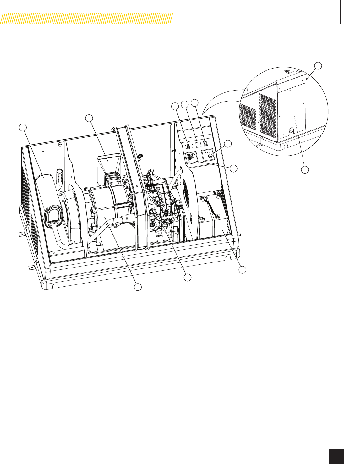
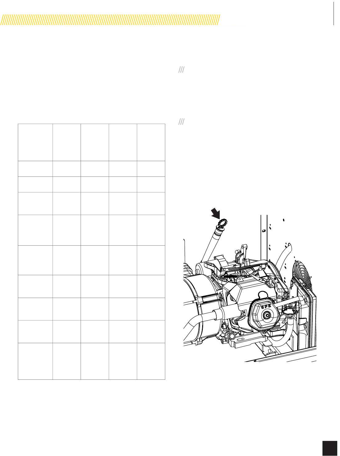
COMPONENT IDENTIFICATION –
ENGINE
2
5
4
3
1
Figure 2
1. Engine Starter
2. Engine Oil Dipstick
3. Spark Plug
4. Fuel Mixture Valve
5. Air Cleaner
CONTROL PANEL
MAIN CIRCUIT BREAKER
The 35.5-amp main circuit breaker protects the generator from
circuit overload. The main circuit breaker controls total output of
the generator. (Figure 3)
ON
MARCHE
ENCENDIDO
OFF
ARRÊT
APAGADO
MAIN CIRCUIT BREAKER
DISJONCTEUR PRINCIPAL
INTERRUPTOR DE CIRCUITO PRINCIPAL
Figure 3
EXERCISE SWITCH
The exercise switch incorporates a built-in timer. The generator
will automatically perform an exercise period once every
seven days (168 hours). At the start of the exercise period, the
engine will start and run for 15 minutes. Load transfer from the
generator output will not occur unless the utility power is lost.
When the switch is in the OFF position, the exercise function is
disabled. Refer to Set Exercise Time to reset. (Figure 4)
EXERCISE / EXERCICE
EJERCICIO
ON
MARCHE
ENCENDIDO
OFF
ARRÊT
APAGADO
Figure 4
Model 100199
GENERAL INFORMATION
15
© 2015 Champion Power Equipment Part No. 101048
SET EXERCISE TIME
To set the exercise time, the engine control module switch
must be in the ATS mode. Decide on the desired day and time
to exercise the generator. Press the exercise switch to ON. The
generator will start and run for 15 minutes and then shut off.
The exercise time is now set. The generator will begin the next
exercise period exactly 168 hours from when the exercise switch
was pressed to the ON position.
If you choose to change the current exercise time setting, choose
the new day and time and cycle the exercise switch from off to
on and it will begin the cycle again. (Figure 4)
The exercise time will have to be reset if:
t The battery was disconnected from the generator
t The switch was moved to the OFF position for
maintenance
HOUR METER
The generator is equipped with an hour meter that will display
the generator actual run and exercise times.
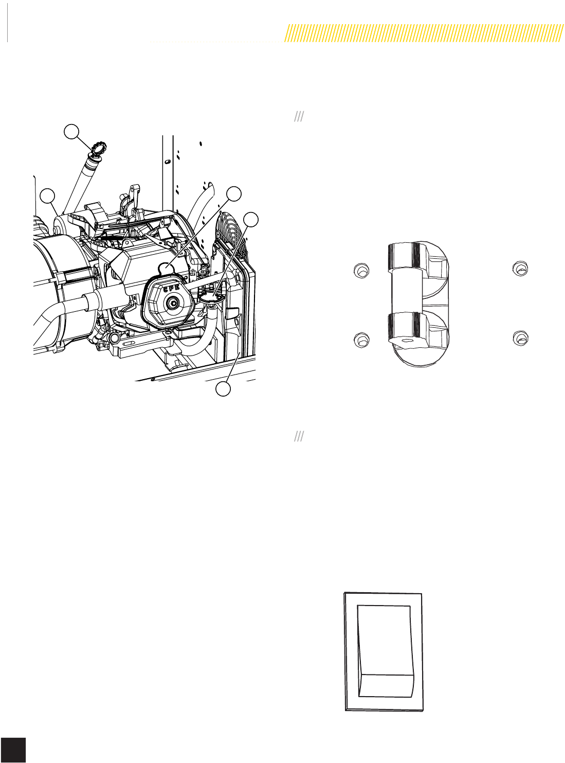
ENGINE CONTROL MODULE
The engine control module contains the ATS/OFF/Manual mode
switch and the LEDs that indicate if a generator operation is
being performed or if there is an active alarm. (Figure 5)
If the exterior fault code indicator light is on, open the enclosure
to view the engine control module. Determine what the fault code
is and remedy the situation or have the generator serviced by an
authorized Service Dealer or contact Champion Customer Service
at 1-877-338-0999.
RESET FAULT CODE(S)
There is also an exterior fault code indicator light located on the
back of the enclosure. This should be checked weekly to make
sure there are no active fault codes.
The fault code(s) can be reset by placing the Engine Control
Module (Figure 5) in the OFF position. This will reset fault LED,
however if a fault code(s) re-occurs it must be addressed.
APAGADO
ARRÊT
OFF
Manual
Manuel
Manual
ATS
ATS
ATS
Hz over/under / Hz plus / sous
Hz Más / Menos
Run / Marche
Funcionar
Power / Alimentation
Potencia
High engine temperature
Surchauffe moteur
Alta temperatura del motor
Low oil / Huile basse
Baja de aceite
Over crank
Surdémarrage
Sobre manivela
Exercise / Exercice /
Ejercicio
Low battery /
Batterie faible
Batería baja
Figure 5
MODE SWITCH
t ATS – This position allows for fully automatic operation. If
utility power is lost, the generator will automatically start
up. It also allows the generator to automatically perform
the exercise period.
t OFF – This position shuts down the engine and prevents
automatic operation of the generator.
t Manual – This position allows manual starting of the
engine. Load transfer from the generator output does not
occur unless the utility power is lost.
EXERCISER LED
The green LED will be lit when the generator is performing the
excercise period. When the exercise period has completed, the
LED will turn off.
LOW BATTERY LED
The red LED will be lit if the battery voltage fell below 21.0 volts
for at least one minute while the engine was running. If battery
voltage rises above 21.1 volts, the LED will turn off. Battery
voltage is not monitored when cranking the engine.
Model 100199
GENERAL INFORMATION
16 Part No. 101048
HZ OVER / UNDER SPEED LED
The red LED will be lit if the engine was operating above or
below its preset speed limit. The engine will shut down, and the
LED will remain lit until the generator is repaired and operating
correctly. Appliances connected to the generator circuit could be
damaged from high generator output if the engine is allowed to
operate above its preset limit. If this failure occurs, contact an
authorized Service Dealer or contact Champion Customer Service
at 1-877-338-0999.
HIGH ENGINE TEMP LED
The red LED will be lit if the engine operating temperature
is too high. It could be from an excessive load, high ambient
temperature or engine over speeding.
LOW OIL LED
The red LED will be lit if the engine oil level has dropped below
the safe operating level. When this happens, the engine will shut
down. Check the engine oil level before attempting to restart the
engine. The engine will not start until the problem is corrected.
OVER CRANK LED
The red LED will be lit if the engine tried to start but was
unable to start in the specied time period. The engine will try
to start ve times and if unsuccessful the light will turn on. This
may occur on initial start-up, the fuel system needs to be fully
pressurized to start and operate. Follow reset procedure on page
15.
RUN LED
The green LED will be lit indicating the engine is running.
POWER LED
The green LED will be lit indicating the generator is working
correctly and loads can be connected to it.
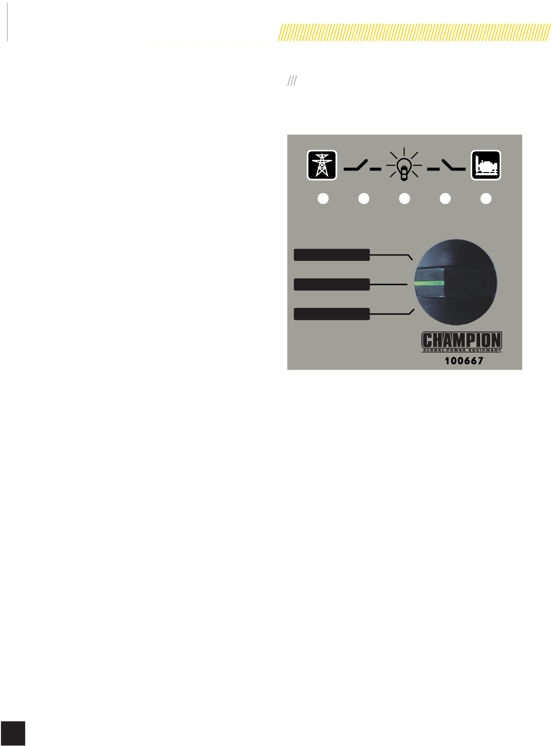
ATS CONTROL MODULE
The ATS control module contains the TEST/AUTO/OFF switch and
LEDs that indicate type of power delivery. (Figure 6)
AUTO / AUTO / AUTOMÁTICO
OFF / ARRÊT / APAGADO
TEST / ESSAI / PRUEBA
UTILIDAD
UTILITÉ
UTILITY
CARGA
CHARGER
LOAD
GENSET
GENSET
GENSET
Figure 6
TEST/AUTO/OFF SWITCH
t TEST – This position allows verication that the generator
power delivery circuit is functional. With the switch in
the TEST position, the engine will start and the ATS will
transfer. The GENSET LED, ATS LED (middle LED) and
LOAD LED should be lit, indicating the generator power
delivery circuit is functional.
t AUTO – This position allows automatic delivery of power
from the generator if there is a utility outage. With the
switch in the AUTO position and the engine not running,
the UTILITY LED, ATS LED (middle LED) and LOAD LED
should be lit, indicating the household is using utility
provided power.
t OFF – This position will not allow any power to be
delivered to the ATS when the engine is running.
Model 100199
GENERAL INFORMATION
17
© 2015 Champion Power Equipment Part No. 101048
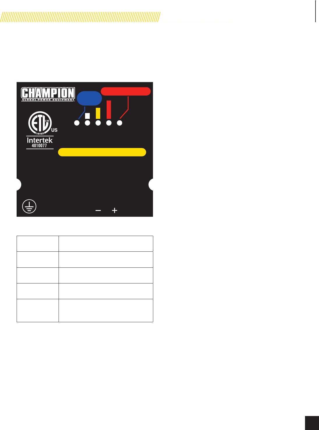
BATTERY CHARGER
The LEDs on the battery charger indicate the state of the
battery’s charge level. Battery charger rating 24 Vdc 1.6A.
(Figure 7)
NO CHARGE / PAS DE CHARGE /
SIN CARGO
AUTOMATIC BATTERY CHARGER /
CHARGE AUTOMATIQUE DE BATTERIE /
CARGADOR DE BATERÍA AUTOMÁTICO
Output: 24 Vdc 1.6 A
Producción: 24 V C.C. 1,6 A
Sortie : 24 V c.c. 1,6 A
Power: 80-125 Vac 1.0 A 50 / 60 Hz
Potencia: 80 - 125 V C.A. 1,0 A 50 / 60 Hz
Alimentation : 80-125 V c.a. 1,0 A 50 / 60 Hz
LN ADJ
E. O.
V
POWER / ALIMENTATION /
POTENCIA
OUTPUT / SORTIE /
PRODUCCIÓN
MODEL / MODÈLE / MODELO : 100482
POWER
ALIMENTATION
POTENCIA
Conforms to UL
Std. 1236
RECOGNIZED
COMPONENT
Figure 7
POWER When lit, it indicates the battery is fully
charged.
Small Bar When lit, it indicates the battery is
receiving a trickle charge.
Middle Bar When current output is near 50%, the LED
turns on.
Large Bar When LED light is on, the charger is
operating above 50% capacity.
NO CHARGE
When lit, it indicates a problem with
the battery or battery charger. See
TROUBLESHOOTING on page 35.
EMISSION REQUIREMENTS
This engine-powered generator meets all United States
Environmental Protection Agency (EPA) Phase 3 requirements
and is approved in both the USA and Canada.
This generator is certied to operate on pipeline NG and LPG
(vapor) fuel for use as a stationary engine for standby power
generation. Federal and/or local laws may be violated if it is used
for any other purpose.
The maintenance schedule must be followed to ensure that the
engine complies with the applicable emission standards for the
duration of the engine’s life.
The following components on the engine consist of the emission
control system:
t Fuel metering system – mixer and fuel regulator
t Air induction system – air cleaner housing and element
t Ignition system – spark plug and ignition module
The emissions compliance period for which the engine has been
shown to meet federal emission requirements is stated on the
emission compliance label attached to the engine. Emission
Control System Warranty found at the end of this manual.

Model 100199
GENERAL INFORMATION
18 Part No. 101048
SPECIFICATIONS
Home standby generator
Maximum continuous power, LPG 8.5 kW
Maximum continuous power, NG 7.5 kW
Rated voltage 120/240
Amps 70.8/35.4 LPG, 62.5/31.25 NG
Harmonic distortion Less than 5%
Main line circuit breaker 35.5 amp
Phase Single
Frequency 60 Hz
Unit weight 365.1 lb. (165.6 kg)
Size (L x W x H) 49.1 x 28 x 28.3 in. (124.7 x 71 x 72 cm)
Engine
Type Champion OHV
No. of cylinders 1
Displacement 439 cc
Cylinder block Aluminum with cast-iron sleeve
Ignition system Solid state – magneto
Spark plug F7RTC (NGK BPR7ES)
Governor Mechanical
Compression ratio 9.5:1
Starter Electric 24V DC
Oil capacity 1.2 qt (1.1 L)
RPM 3600
Controls
Mode switch auto Auto start on utility failure
Mode switch manual Starts on demand
Mode switch off Stops unit/control and charger active
Ready to run/maintenance messages Standard
Programmable start delay Standard
Engine start sequence Standard
Starter lockout Standard
Battery charger/low battery indicator Standard
Charger fault Standard
AVR over voltage protection Standard
Low oil protection Standard
Safety fused Standard
Overcrank/overspeed/underspeed protection Standard
Model 100199
GENERAL INFORMATION
19
© 2015 Champion Power Equipment Part No. 101048
FUEL SYSTEM
The engine is tted with a dual master mixer assembly
carburetion system, which allows it to run on either NG or
LPG. It has been congured at the factory to run on NG. If your
installation requires the engine to run on LPG, orices in the
master mixer assembly carburetor must be changed.
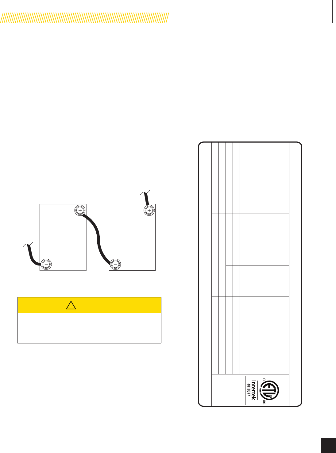
BATTERY REQUIREMENTS
Champion requires two (2) 12 volt batteries with a minimum of
18 Ah with a minimum of 270 CCA each. [battery size: 6-7/8
L x 3-7/16 W x 6-1/8 H inches (175 mm L x 87 mm W x 155
mm H)]. Purchase the batteries locally. Install the positive battery
cable rst.
Install a cable from the positive (+) terminal of one battery to the
negative (–) terminal of the other battery. Always connect the
positive (+) battery cable to the generator rst. (Figure 8)
Figure 8
! CAUTION
For battery installation, maintenance, and safety
requirements refer to purchased manufacturer battery
installation and safety manual.
BATTERY CHARGING
The generator is equipped with an automatic battery charger. The
charger will sense the battery’s state of charge and automatically
charge the battery when required. LED lights on the charger display
the battery state of charge. See Figure 7 on page 17.
MODEL AND SERIAL NUMBER
The model and serial number plate is afxed to the generator
above the control panel. Have this information if calling for
service or ordering parts. (Figure 9)
CHAMPION POWER EQUIPMENT
12039 Smith Ave., Santa Fe Springs, CA 90670 USA P/N 100970
CARCASA A PRUEBA DE LLUVIA EQUIPADO
BOÎTIER ÉTANCHE À LA PLUIE ÉQUIPÉ
RAINPROOF ENCLOSURE FITTED
RATED CURRENT 70.8 A / 35.4 A (LPG) COURANT NOMINALE 70,8 A / 35,4 A (GPL) CORRIENTE NOMINAL 70,8 A / 35,4 A (LPG)
RATED VOLTAGE 120/240~,single-phase TENSION NOMINALE 120 / 240~,monophasées TENSIÓN NOMINAL 120 / 240~,monofásicas
RATED FREQUENCY 60 Hz FRÉQUENCE NOMINALE 60 Hz FRECUENCIA NOMINAL 60 Hz
POWER FACTOR 1.0 FACTEUR DE PUISSANCE 1,0 FACTOR DE POTENCIA 1,0
MAX LOAD UNBALANCE MAX DÉSÉQUILIBRE DE CHARGE MAX DESEQUILIBRIO DE LA CARGA50% 50 % 50 %
RATED ENGINE SPEED 3600 r/min RÉGIME MOTEUR NOMINAL 3600 r/min VELOCIDAD NOMINAL DEL MOTOR 3600 r/min
RATED AMBIENT TEMP TEMPÉRATURE AMBIANTE NOMINALE TEMPERATURA AMBIENTE NOMINAL25-40 ºC 25-40 ºC 25-40 ºC
AISLANTE CLASEISOLATION DE CLASSE
INSULATION CLASS H H H
Conforms to UL Std.
No. 2200
Certified to
CAN/CSA Standard
C22.2 No. 100
FOR STANDBY SERVICE PARA EL SERVICIO SUPLENTEPOUR LE SERVICE DE SECOURS
NEUTRAL FLOATING NEUTRE FLOTTANT NEUTRO FLOTANTE
100199
STATIONARY ENGINE DRIVEN GENERATOR / STATIONNAIRE GÉNÉRATEUR ENTRAÎNÉ PAR UN MOTEUR /
ESTACIONARIO ACCIONADA POR EL MOTOR GENERADOR
MODEL
MODELO
MODÈLE
Figure 9
1
To Starter
To Ground 2
20
Model 100199
OPERATION
Part No. 101048
Before operating the generator, review SAFETY section starting
on page 5.
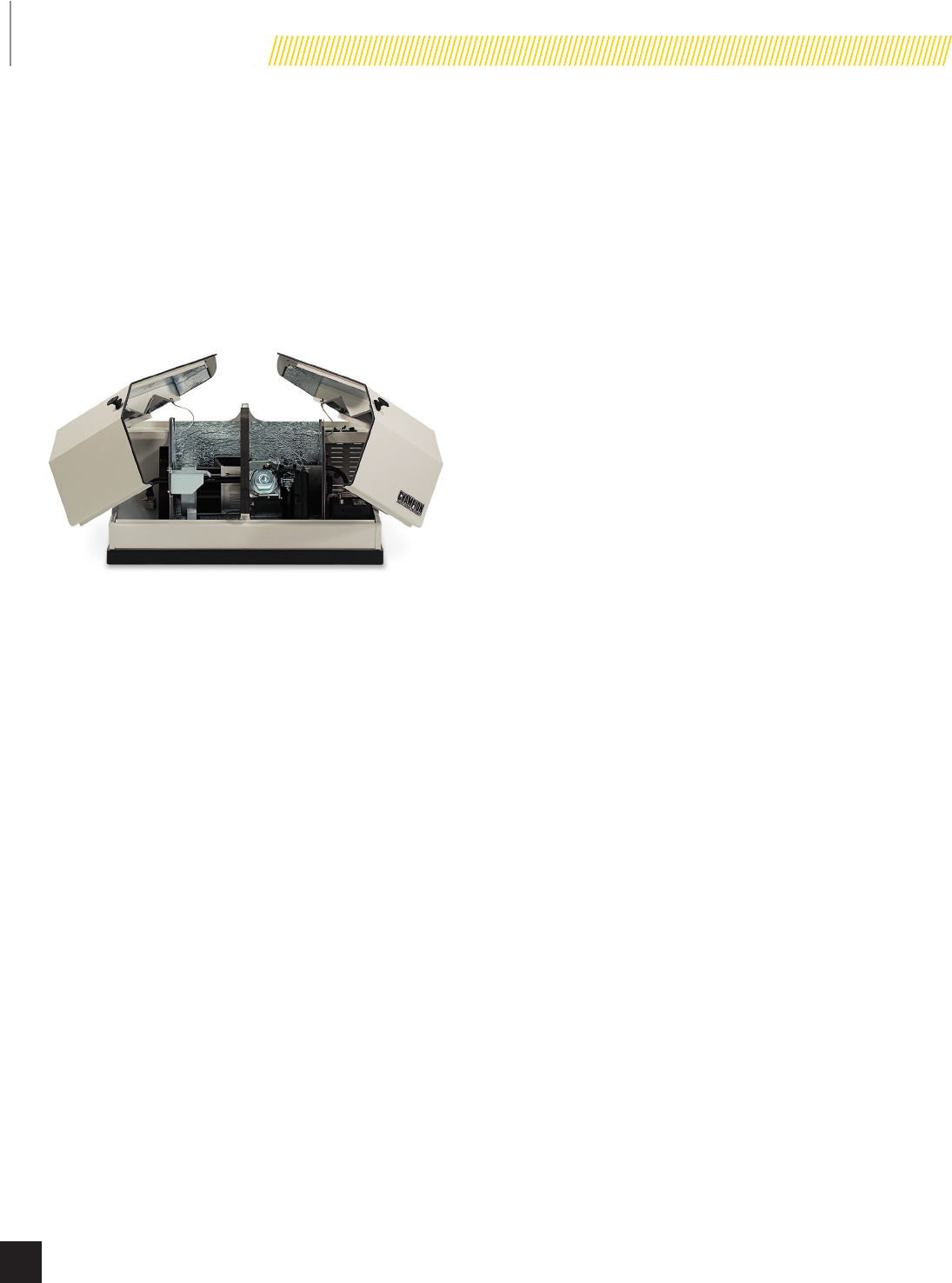
ENCLOSURE AND ACCESS
Open the enclosure to gain access to the generator and its
components. (Figure 10) Unlock the handles. Turn the handles
and lift the hoods up and to the outside.
Figure 10
PRE-START CHECKLIST
To make sure the generator is ready for proper operation, the
following items should be checked:
t Fuel valve is in the ON position
t No fault code LEDs are lit
t Battery is at full charge
t ATS control module is in the AUTO position
t Engine control module is in the ATS position
t Transfer switch lever is in the Utility Power position
TURNING OFF THE GENERATOR
If you need to shut off the generator when it is running, turn
the engine control module switch to the OFF position. This will
shut off the engine. With the engine control module in the OFF
position, the generator will not start, even if there is loss of utility
power.
Model 100199
MAINTENANCE
21
© 2015 Champion Power Equipment Part No. 101048
Before performing maintenance procedures, review SAFETY
section starting on page 5.
Ensure that the ATS and Engine Switches are in the OFF position
before performing any maintenance or cleaning.
SCHEDULED MAINTENANCE
CHART
First
5Hours of
Operation
Weekly Monthly
Every
2Years
or 100
Hours of
Operation
Change
engine oil √√**
Check engine
oil level √*
Inspect fuel
lines and
connections
√
Check
exterior fault
code indicator
light
√
Inspect
and clean
enclosure
louvers
√
Inspect and
clean battery
terminals
√
Inspect and
clean engine
air cleaner
√**
Inspect
engine spark
plug
√
Complete
inspection
of generator
and engine
tune-up
√***
* Monthly or 24 hours of continuous operation
** Service sooner if operating in high ambient temperatures or a
dusty and dirty environment.
*** Maintenance should be performed by your service dealer.
ENGINE OIL
ENGINE OIL REQUIREMENTS
Use American Petroleum Institute (API) Service Class SN or
better. Do not use special additives. All temperatures full
synthetic 5W-30.
CHECKING THE ENGINE OIL LEVEL
Check the oil level daily when the generator is running for an
extended period of time.
1. If the generator is running during a utility outage, turn off
all household loads.
2. Turn the engine control module switch to the OFF position.
3. Remove the dipstick. Wipe it dry with a clean cloth and
completely reinsert it into the dipstick tube. See gure 12,
page 22.
Figure 11
Model 100199
MAINTENANCE
22 Part No. 101048
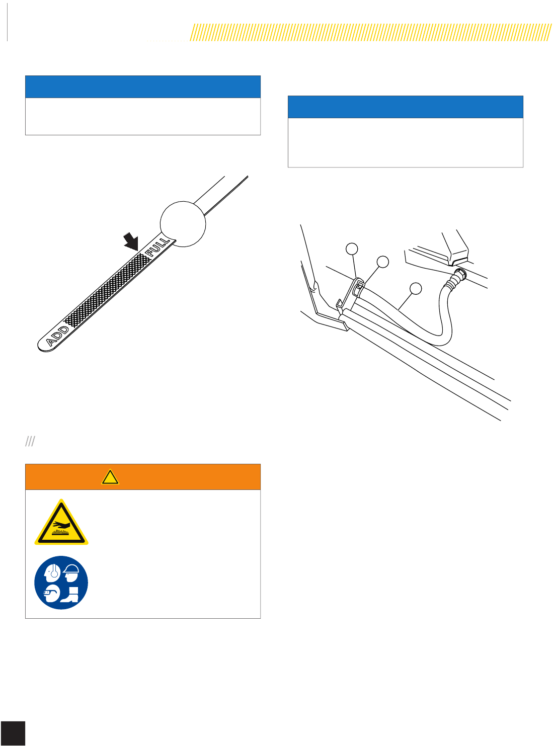
NOTICE
DO NOT overll the engine with engine oil. Damage to the
engine may occur.
4. Remove the dipstick. The oil level should be at the FULL
mark. If necessary, add oil. DO NOT overll.
Figure 12
5. Install the dipstick.
6. Turn the engine control module switch to its prior position.
CHANGING THE ENGINE OIL
! WARNING
Always wear protective glasses
or goggles and protective clothing
when changing hot engine oil.
1. Turn the ATS to the OFF position.
2. Turn the engine control module switch to the MANUAL
position.
3. Allow the engine to run until it reaches operating
temperature.
4. Turn the engine control module switch to the OFF position.
NOTICE
Always be environmentally responsible. Consult the local
authorities or reclamations facility for proper disposal of
engine oil waste.
5. Position drain pan under alternator.
6. Loosen hose clamp on oil drain hose and slide drain hose
off retaining pin. (Figure 13)
1
2
3
Figure 13
1. Oil Drain Hose
2. Hose Clamp
3. Retaining Pin
7. Position drain hose into drain pan and allow crankcase to
empty.
8. Reinstall the hose onto the retaining pin and reposition
hose clamp.
9. Fill the engine with the proper amount of engine oil. See
Figure 12.
10. Turn the engine control module switch to its prior position.
11. Turn the ATS to the AUTO position.
Model 100199
MAINTENANCE
23
© 2015 Champion Power Equipment Part No. 101048
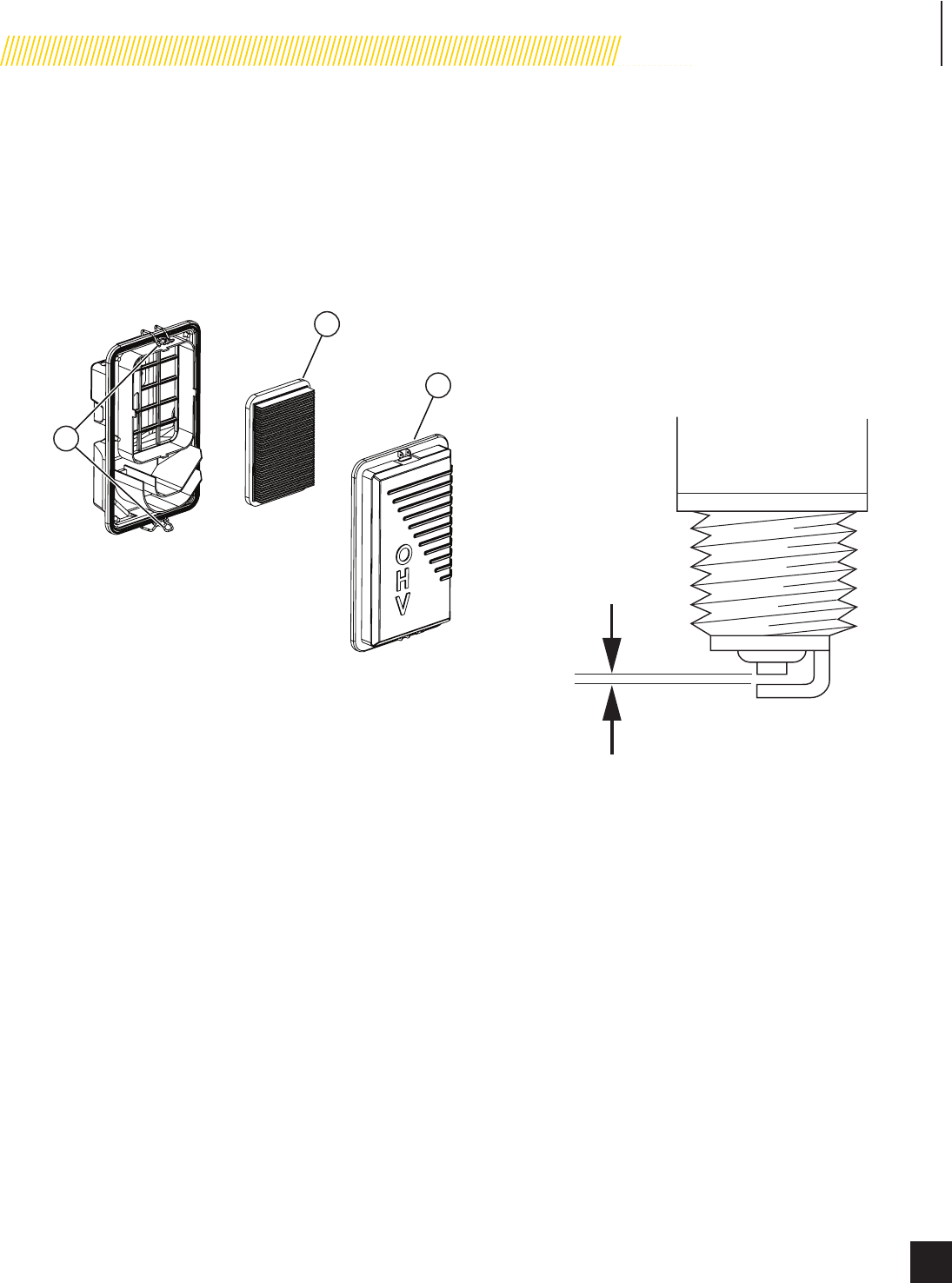
INSPECT AND CLEAN ENGINE
AIR CLEANER
1. Turn the engine control module switch to the OFF position.
2. Unsnap the clips holding the air cleaner cover in place and
remove the air cleaner cover.
3. Remove the paper element.
1
2
3
Figure 14
1. Air Cleaner Cover
Clips
2. Paper Element
3. Air Cleaner Cover
4. Inspect the paper element for any rips or tears. Replace if
damaged.
5. Hold the paper element up to a light. You should be able
to see light through the paper element, if not replace the
element.
6. Install paper element in the air cleaner housing with the
pleats facing towards the air cleaner cover.
7. Install the cover and snap the clips in place.
8. Turn the engine control module switch to its prior position.
SPARK PLUG
1. Turn the ATS to the OFF position.
2. Turn the engine control module switch to the OFF position.
3. Remove the spark plug cable from the spark plug.
4. Clean the area around the spark plug to keep dirt out of
the engine and remove the spark plug.
5. Inspect the spark plug electrode and replace the plug if
the electrode shows signs of deterioration.
6. Check the gap before installing the spark plug. The spark
plug gap should be 0.028 – 0.031 in. (0.7 – 0.8 mm).
0.028 - 0.031 in.
(0.7 - 0.8 mm)
Figure 15
7. Carefully thread the spark plug into the engine and tighten
to 20-30 N-m (14.8-22.1 lbf-ft).
8. Re-connect the spark plug cable.
9. Turn the engine control module switch to its prior position.
10. Turn the ATS to the AUTO position.
Model 100199
MAINTENANCE
24 Part No. 101048
BATTERY MAINTENANCE
1. Turn the engine control module switch to the OFF position.
2. Inspect the battery cables and terminals for corrosion.
3. Check that the cables are securely fastened to the
terminals.
4. Check the ground lug and make sure the connections are
tight.
5. Check the uid level of the battery, unless sealed. If low,
top off the level using distilled water only.
Follow all battery instructions provided by the battery
manufacture.
CORROSION PROTECTION
NOTICE
Never use a pressure washer to wash the interior of the
generator with water.
Wash the outside of the enclosure using a mild soap and water.
Use an automotive-type wax and wax the outside of the enclosure
to protect it from the elements. If used in a salt water/coastal
area, the enclosure should be washed more frequently to prevent
corrosion. Spray light oil on the hinges for the enclosure doors.
MAINTENANCE AFTER
SUBMERSION
! WARNING
!
Never try to start or operate the
generator if it has been submerged
underwater or exposed to a ood.
If the generator has been in conditions where it became
submerged underwater, the generator must be inspected and
maintenance must be performed before returning the generator
to service.
Turn engine control module and ATS control module to the
OFF position. Have a authorized Champion Dealer inspect the
generator and perform any necessary maintenance.
If the house or building has been exposed to a ood, it should
be inspected by a certied electrician for any electrical problems
that may occur if the generator is put back into service or if utility
power is restored.
STORAGE
If the generator is not going to be used for several months and
not exercised every 7 days, it should be prepared for storage.
1. Manually start the engine and run it for several minutes to
allow it to warm up.
2. With the engine running, turn the fuel shutoff valve to the
closed position and let the engine continue to run until it
shuts down.
3. Once the engine has shut down, turn the engine control
module switch and the ATS control module switch to the
OFF position.
4. Switch the generator’s main circuit breaker to the OFF
(OPEN) position.
5. Turn off the utility power to the transfer switch.
6. Disconnect the battery cables. Remove the negative cable
rst.
7. Change the engine oil. See CHANGING THE ENGINE OIL on
page 22.
8. Remove the spark plug and spray fogging oil into the
spark plug hole. Install the spark plug and tighten.
9. Thoroughly wash and wax the exterior of the generator
enclosure. Do not use a pressure washer.
Model 100199
MAINTENANCE
25
© 2015 Champion Power Equipment Part No. 101048
RETURN TO SERVICE AFTER
STORAGE
1. Make sure the utility power to the transfer switch is off.
2. The engine control module switch and the ATS control
module switch should be in the OFF position.
3. Check the engine oil level. Add oil if needed.
4. Recharge the batteries to 100% state of charge. If the
batteries will not fully charge, replace the batteries.
! WARNING
!
Always connect the positive
(+) battery cable rst. After the
positive cable is connected, then
the negative (-) battery cable can
be attached. This minimizes the
possibility of electrical contact.
5. Connect the positive (+) battery cable to the positive
(+) battery terminal rst and then connect the negative
battery cable to the negative (-) battery terminal.
6. Clean and wipe down the generator with mild soap and
water.
7. Turn the fuel shutoff valve to the ON position.
8. Turn the engine control module switch to the manual
position. The engine should start. Run the engine for 15
minutes to allow it to warm up. The fuel system might
require more than one start cycle to fully pressurize the
fuel system for operation.
9. Make sure there are not any active fault codes.
10. Turn the engine control module switch to the OFF position
to shut off the engine.
11. Turn the ATS module switch to the AUTO position.
12. Turn on the utility power to the transfer switch. The utility
LEDs on the ATS module should be lit.
13. Turn the engine control module switch to the ATS position.
14. Set the exercise time. See EXERCISE SWITCH on pages
14 and 15.
Model 100199
MAINTENANCE
26 Part No. 101048
34
55
29
96
97
98
99
82
100
101
104
103
102
76
1
2
345
6
7
8
10
14 15 16 17 18
19
21
22
23
1
24
18
25
27
9
28
30
31
32
33
35
36
37
38
39
40
41
42
1
43
44
46
47
48
49
50
51
56
57
59
60
61
62
63
64
65
66
67
68
69
70
71
72
73
77
78
79
58
74
75
45
85
86
87
90
80
91 92
93 94 95
9
84
20
83
88
82 81
12
11
26
1
13
54
52
53
89
1
14
105
80
106
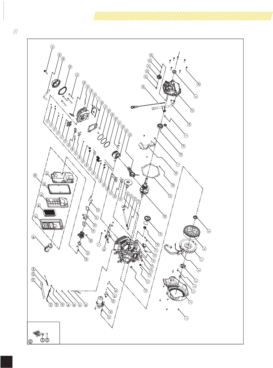
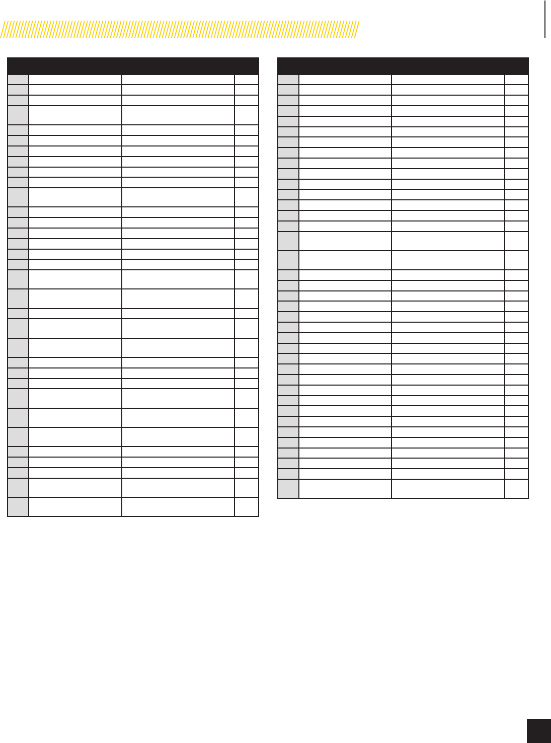
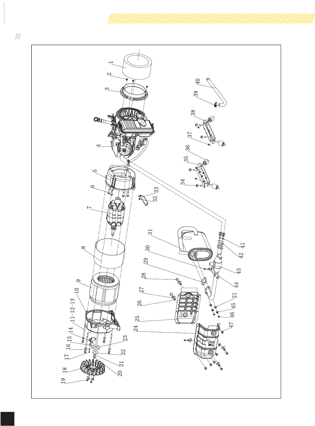
ENGINE PARTS
Model 100199
MAINTENANCE
27
© 2015 Champion Power Equipment Part No. 101048
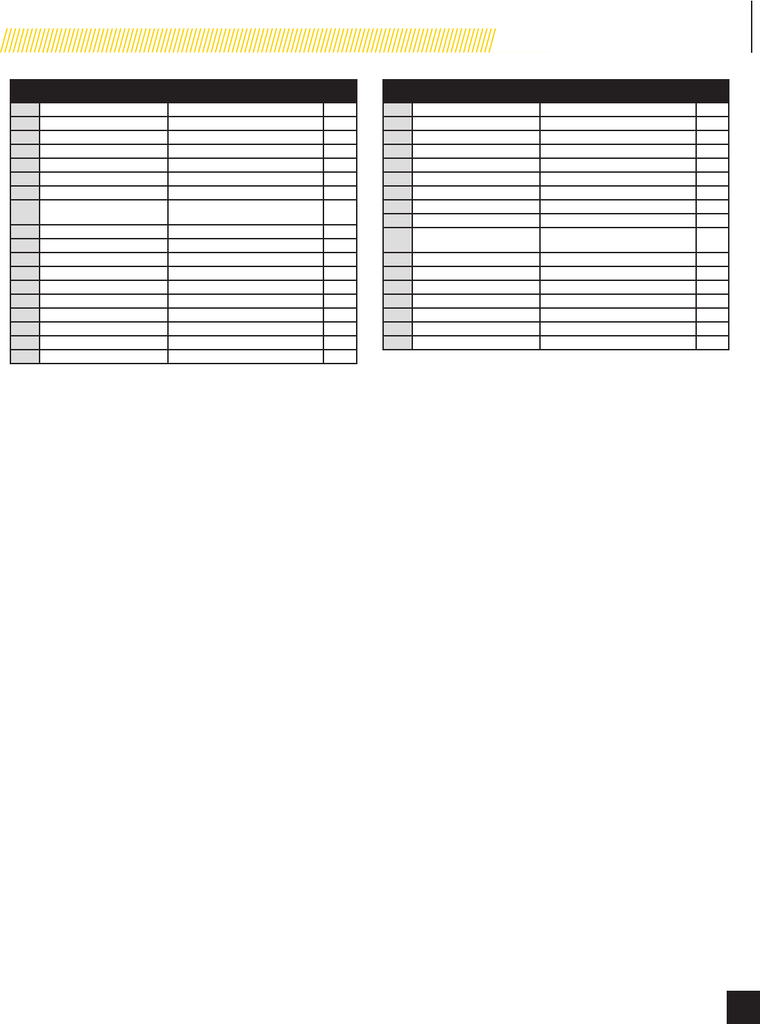
# Part Number Description Qty
11.5789.0612 Flange Bolt M6 × 12 12
247.080100.01.2 Fan Cover, Black 1
32.02.007 Nut M16 × 1.5 1
41.5789.0629 Flange Bolt M6 × 29 2
547.080005.00 Plate, Fan 1
646.123000.01 Ignition Coil 1
747.080001.00 Cooling Fan 1
846.120100.05 Flywheel, Electric Start 1
92.11.007 Oil Seal, Ø35 × Ø52 × 8 2
10 45.030032.00 Sheath, Wire 1
11 1.9074.4.0306 Screw M3 × 6 2
12 5.1050.001 Sensor, Oil Temperature 1
13 2.08.039 Drain Bolt, M12 × 1.5 × 15 1
14 2.03.023 Washer, Ø12.5 × Ø20 × 2 2
15 47.030100.04 Crankcase 1
16 45.127000.02 Oil Level Sensor 1
17 1.5789.0615 Flange Bolt M6 × 15 2
18 1.276.6202 Bearing 6202 2
19 47.050006.00 Weight Balancer 1
20 47.050100.01 Crankshaft 1
21 46.030008.00 Gasket, Crankcase Cover 1
22 2.04.001 Dowel Pin, Ø9 × 14 2
23 46.080600.00 Air Guide, Right Side 1
24 1.276.6207 Bearing 6207 1
25 47.031100.00 Tube, Oil Fill 1
26 47.031300.00.48 Dipstick Assembly, Yellow 1
27 45.030007.03 Cover, Crankcase, LPG/NG 1
28 1.5789.0840.0.8 Flange Bolt M8 × 40 7
29 2.03.021.1 Washer, Ø6.4 × Ø13 × 1, Black 1
30 45.110013.00 Shaft, Governor Gear 1
31 45.110100.00 Gear, Governor 1
32 21.110011.00 Clip, Governor Gear 1
33 45.110012.00 Bushing, Governor Gear 1
34 47.050200.00 Connecting Rod 1
35 47.050005.01 Piston 1
36 2.09.004 Circlip, Ø21 × Ø1 2
37 45.050003.00 Pin, Piston 1
38 46.050303.02 Ring, Oil 1
39 46.050302.02 Ring, Second Piston 1
40 46.050301.02 Ring, First Piston 1
41 2.04.004 Dowel Pin, Ø12 × 20 2
42 47.030009.00 Gasket, Cylinder Head 1
43 46.080400.00 Air Guide, Lower 1
44 47.010100.04 Cylinder Head 1
45 2.01.010 Stud Bolt M8 × 35 2
46 2.15.008(F7RTC) Spark Plug, F7RTC 1
47 2.08.122 Flange Bolt M10 × 100 4
48 46.020002.00 Gasket, Cylinder Head Cover 1
49 47.021000.00 Cylinder Head Cover, CPE 1
50 45.020001.02 Breather Tube 1
51 47.020100.00 Bolt, Cylinder Head Cover 1
52 45.032000.00 Fuel Guide Assembly 1
53 2.06.013 Clamp, Ø13.5 × b10 1
54 45.030200.00 Support 1
55 47.041000.02 Camshaft 1
56 47.040004.00 Lifter, Valve 2
57 47.040002.00 Valve, Intake 1
58 47.040006.00 Valve, Exhaust 1
59 46.040005.00 Push Rod 2
60 45.040015.00 Retainer, Valve Spring 2
61 45.040017.00 Oil Seal, Valve 2
# Part Number Description Qty
62 45.040003.00 Spring, Valve 2
63 23.040010.00 Bolt, Rocker Arm 2
64 45.040001.00 Retainer, Intake Valve Spring 1
65 45.040007.00 Retainer, Exhaust Valve Spring 1
66 45.040008.00 Rotator, Exhaust Valve 1
67 46.040004.00 Guide Plate, Push Rod 1
68 46.040016.00 Shaft, Rocker Arm 1
69 46.040201.00 Retainer, Rocker Arm 1
70 46.040009.00 Rocker Arm, Intake Valve 1
71 46.040018.00 Rocker Arm, Exhaust Valve 1
72 1.97.1.06 Washer Ø6 2
73 22.040012.00 Screw, Valve Adjustment 2
74 1.6177.1.06 Flange Lock Nut M6 2
75 21.040021.00 Lock Nut, M6 × 0.5 2
76 2.01.008 Stud Bolt M6 × M8 × 105 2
77 46.130002.20 Gasket, Insulator 1
78 45.130001.00 Insulator, Carburetor 1
79 46.130003.20 Gasket, Carburetor 1
80 161.133000.00 Master Mixer Assembly, LPG/NG 1
81 46.130004.20 Gasket, Air Cleaner 1
82 1.6177.06 Flange Nut M6 3
83 46.091100.03 Base, Air Cleaner 1
84 45.091002.20 Seal, Air Cleaner 1
85 45.091001.20 Separator, Air Cleaner 1
86 47.091300.00 Element, Air Filter Ul Paper 1
87 47.091200.00 Cover, Air Cleaner 1
88 47.091000.00 Air Cleaner Assembly 1
89 47.090004.00 Pipe, Air Cleaner 1
90 46.080300.20 Air Guide, Upper 1
91 1.5789.0835 Flange Bolt M8 × 35 2
92 46.125100.03 Starter Motor Assembly 1
93 45.125200.00 Relay, Starter 1
94 1.93.05 Lock Washer Ø5 2
95 1.16674.0516 Flange Bolt M5 × 16 2
96 45.110001.00 Shaft, Governor Arm 1
97 2.03.019 Washer, Ø8.2 × Ø17 × 0.8 1
98 2.11.006 Oil Seal, Ø7 × Ø14 × 5 1
99 45.110008.00 Pin, Shaft 1
100 45.110003.00 Arm, Governor 1
101 2.08.040 Bolt, Governor Arm, M6 × 21 1
102 45.110006.00 Rod, Governor 1
103 45.110005.00 Spring, Throttle Return 1
104 45.110007.00 Spring, Governor 1
105 161.133029.00 Metering Jet, Main, LPG 1
161.133029.01 Metering Jet, Main, NG 1
106 161.133030.00 Metering Jet, Idle, LPG 1
161.133030.01 Metering Jet, Idle, NG 1
Model 100199
MAINTENANCE
28 Part No. 101048
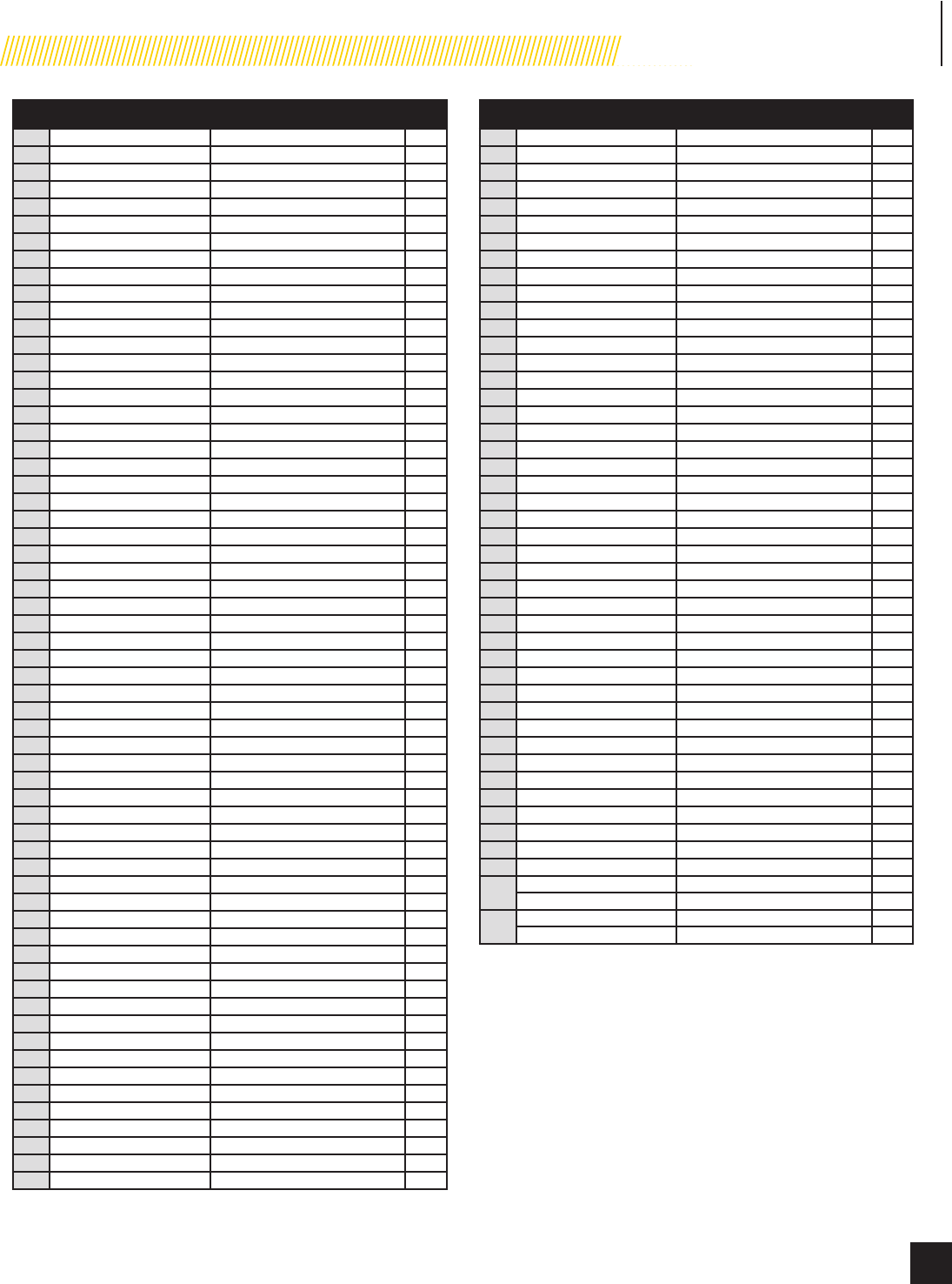
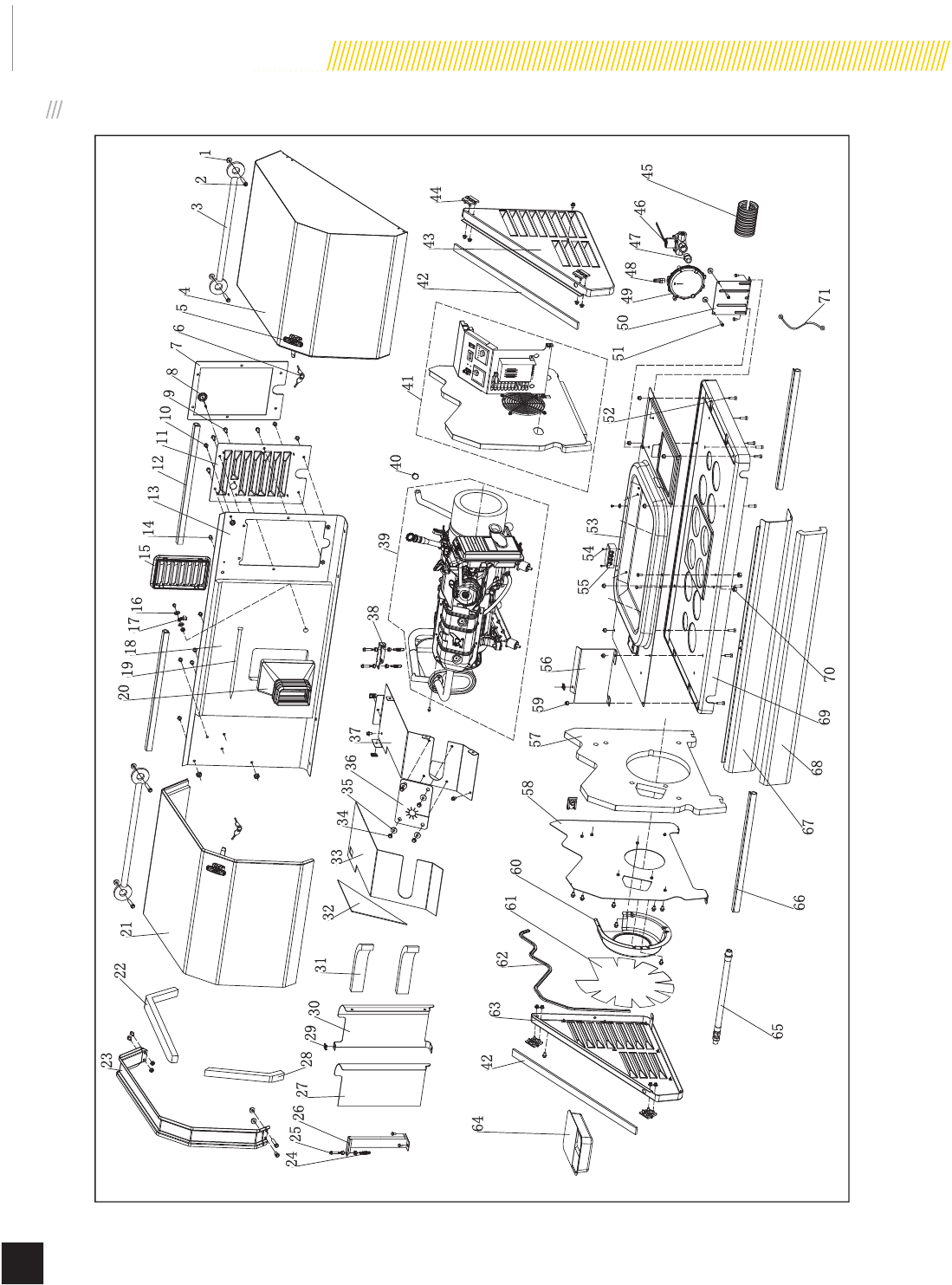
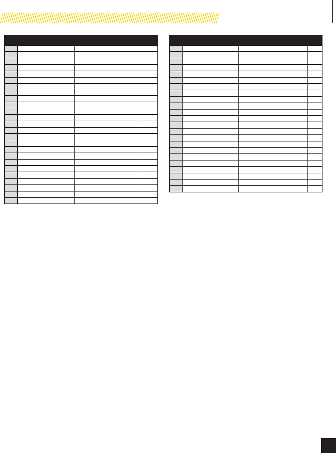
ENCLOSURE AND ASSEMBLIES
1
2
3
4
7
10 9
11
12
13
15 14
16
17
18
19
20
21
22
23
27 28 29 30 31 32 33 34 35 36 37
39
40
41
42 43 44
38
26
50 49 47 46
48
53
56
57
58
60
61
62
63
42
65
66 67 68
51
52
59
24 25
54
55
64
69
8
45
70 71
5
6
Model 100199
MAINTENANCE
29
© 2015 Champion Power Equipment Part No. 101048
# Part Number Description Qty
11.6177.1.06 Flange Lock Nut M6 23
21.5789.0615 Flange bolt, M6 X 15 5
3161.200507.00 Curb Chain Assembly, Cover 2
4161.200500.01.24 Top Cover Assembly, Right,
Silk Grey 1
5161.200110.00 Hook Lock Assembly 2
6161.200110.00.01 Key, Hook Lock 2
7161.200021.16 Seal, Access Cover 1
881.200503.00 Plug 1
91.16674.0820 Flange bolt, M8 X 20 7
10 1.16674.0812 Flange bolt, M8 X 12 23
11 161.200402.00.24 Access Cover, Electric Cabinet,
Silk Grey 1
12 161.200109.03 Rubber Strip, 575 mm 2
13 161.200401.00.24 Rear Cover, Silk Grey 1
14 5.1460.015 Indicator Light, 24 v 1
15 161.192100.00 Supporter, Air Guide, Alternator 1
16 1.862.06 Toothed Lock Washer, Ø6 3
17 5.1560.000 Ground Wire Teminal, Ø6, UL 1
18 161.200021.05 Acoustic Panel, Rear Center
Chamber 1
19 9.3410.02 Locking Nylon cable ties, 5 X
500 mm 1
20 161.192300.00 Air Guide, Alternator 1
21 161.200500.00.24 Top Cover Assembly, Left, Silk
Grey 1
22 161.200021.17 Seal Strip, Top Cover, Long,
625 X 50 X 25 mm 1
23 161.201600.02.1 Gutter, Black 1
24 161.100006.00 Spring , Muffler 3
25 2.08.119 Flange Bolt M8 X 35, Muffler 3
26 161.1010005.01.2 Supportor, Muffler, Bottom,
Black 1
27 161.200021.13 Acoustic Panel, Muffler Cover,
Front 1
28 161.200021.18 Seal Strip, Top Cover, Short,
50 X 320 X 25 mm 1
29 2.02.032 Cage Nut, M8 5
30 161.200017.03.24 Muffler Cover, Back, Silk Grey 1
31 161.200021.15 Foams, Muffler Cover, Back 2
32 161.200021.14 Acoustic Panel, Muffler Cover,
side 1
33 161.200021.06 Acoustic Panel, Muffler Cover,
top 1
# Part Number Description Qty
34 1.5789.0612 Flange Bolt, M6 X 12 6
35 2.03.004 Washer, Ø24 X Ø6.5 X 1.5 4
36 161.200017.02 Thermal Baffle 1
37 161.200017.00.24 Muffler Cover, Top, Silk Grey 1
38 161.1010005.00.2 Supportor, Muffler, Top, Black 1
39 100199.901 Generator Assembly 1
40 2.06.035 Clamp, Ø23.5 1
41 100199.902 Control Panel Assembly 1
42 161.200021.02 Seal Strip, Right/Left Cover 2
43 161.200302.00.24 Right Cover Assembly, Silk Grey 1
44 161.201900.00 Hinge 4
45 5.1320.018 Plastic Conduit, CSA, 100 mm 1
46 161.134100.00 Solenoid Valve, LPG/NG 1
47 161.133106.01 Nipple, NPT 3/4 1
48 161.133106.00 Nipple, NPT 3/8 1
49 161.136000.00 Pressure Reducing Valve, LPG/
NG 1
50 161.200018.00 Supportor, Pressure Reducing
Valve 1
51 1.5789.0629 Flange bolt, M6 X 29 2
52 1.5781.0825 Bolt, M8 X 25 8
53 161.200601.00.24 Base Center, Silk Grey 1
54 1.823.0414 Screw, M4 X 14 2
55 161.210011.00 Terminal Block, 60A 1
56 161.200017.01.24 Muffler Cover, Front, Silk Grey 1
57 161.200021.03 Acoustic Panel, Left Firewall 1
58 161.200005.01.24 Firewall, Left, Silk Grey 1
59 1.6177.1.08 Flange Lock Nut, M8 9
60 161.192300.01.2 Fan Cover, Rotor, Black 1
61 161.200021.12 Foams, Fan Cover 1
62 161.200109.01 Rubber Strip, 1120 mm 1
63 161.200201.00.24 Left Cover, Silk Grey 1
64 161.200023.00.1 Oil Container, Black 1
65 161.130021.01 LPG Hose With NPT3/4 Nipple 1
66 161.200109.02 Rubber Strip, 530mm 2
67 161.200101.00.24 Front Cover , Silk Grey 1
68 161.200021.11 Foams, Front Cover 1
69 161.201800.00 Plastic Pallet, PP 1
70 1.6182.08 Nut, M8 2
71 5.1900.074 Battery Jump Wire, 225 mm,
6AWG 1
Model 100199
MAINTENANCE
30 Part No. 101048
1
2
3
4
5
6
7
8
9
10
11 12 13
14
15
16
17
18
19
20 21 22 23
25
28 29 30 31
32 33
34 35 36 37 38 39 40
41
42
43
47
26 27
24
44
21
45
46
ALTERNATOR AND EXHAUST SYSTEM
Model 100199
MAINTENANCE
31
© 2015 Champion Power Equipment Part No. 101048
# Part Number Description Qty
1161.200021.00 Foams Ring, Engine Fan 1
21.5789.0608 Flange Bolt, M6 X 8 3
3161.200024.00.1 Supportor, Air Guide Cover 1
447.692 Engine 1
5161.190007.00 Crankcase Cover 1
61.5789.1022 Flange Bolt, M10 X 22 4
7161.191100.00 Rotor Component, Ø175 X
Ø225 X 120 1
8161.191002.00 Stator Cover 1
9161.191200.00 Stator Assembly, Ø230 X 120 1
10 161.190002.00 End Housing 1
11 2.08.110 Bolt, M8 X 170 4
12 1.93.08 Lock Washer, Ø8 9
13 1.848.08 Washer, Ø8 6
14 161.190300.00 Carbon Brush Assembly 1
15 122.190004.01 Pinch, Carbon Brush 1
16 1.93.05 Lock Washer, Ø5 1
17 1.5783.0520 Bolt, M5 X 20 1
18 161.190001.00 Rotor Fan, 8KW 1
19 1.5789.0629 Flange Bolt, M6 X 29 4
20 2.08.113 Flange Bolt, M10 X 340 1
21 1.7244.10 Lock Washer, Ø10 3
22 2.03.050 Washer, Ø25 X Ø10.2 X 2.7 1
23 161.190019.00 Flange Plate, Fan 1
24 161.080009.01.2 Air Guide, Muffler Pipe, Front 1
# Part Number Description Qty
25 161.080009.00.2 Air Guide, Muffler Pipe, Back 1
26 1.93.06 Lock Washer, Ø6 5
27 2.03.004 Washer, Ø24 X Ø6.5 X 1.5 5
28 1.5789.0615 Flange bolt, M6 X 15 5
29 161.101002.00 Gasket, Muffler 1
30 1.16674.0825 Flange Bolt, M8 X 25 1
31 161.101000.00 Muffler Assembly 1
32 1.6177.1.06 Flange Lock Nut M6 1
33 45.090006.20 Holder, Air Cleaner 1
34 1.6177.1.10 Flange Lock Nut, M10 4
35 161.201600.01 Supportor, End Housing 1
36 161.200605.00 Motor Mount 4
37 1.6177.1.08 Flange Lock Nut, M8 8
38 161.201600.00 Supportor, Engine 1
39 2.06.023 Clamp, Ø20 1
40 161.130021.00 Pipe, LPG/NG 1
41 1.6175.08 Nut, M8 2
42 47.100001.00 Gasket, Exhaust Pipe 1
43 161.101001.00 Exhaust Pipe 1
44 1.96.08 Washer, Ø8 1
45 1.6187.1.10 Lock Nut M10, Flange, Metal 2
46 1.6170.10 Nut, M10 2
47 1.5789.0608 Flange bolt, M6 X 8 6
Model 100199
MAINTENANCE
32 Part No. 101048
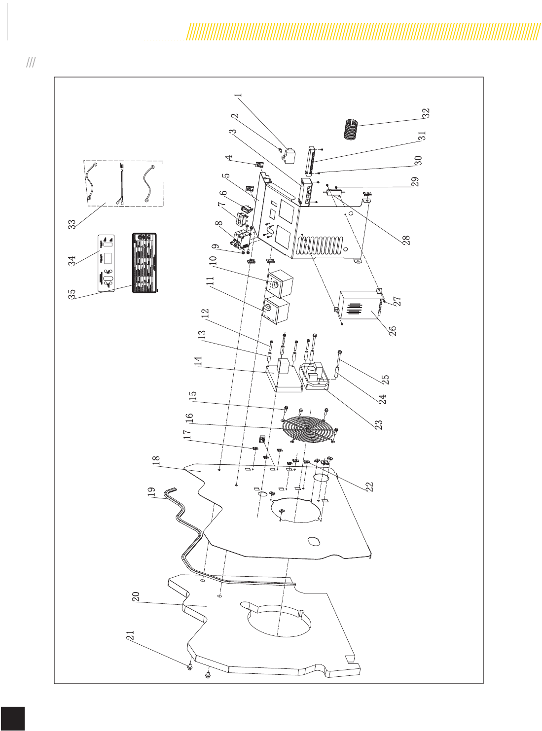
CONTROL PANEL
4
5
6
7
8
9
10
11
13
14
15
16
17
18
19
20
22
24 25
26 27
28
29 30 31
3
33
12
21
23
1
2
32
3435
Model 100199
MAINTENANCE
33
© 2015 Champion Power Equipment Part No. 101048
# Part Number Description Qty
15.1810.000 Over Voltage Protector 1
21.818.0514 Screw, M5X14 1
3161.210011.00 Terminal Block, 60A 1
42.02.032 Cage Nut, M8 7
5161.200004.00.24 Cover, Electric Cabinet, Silk Grey 1
65.1000.006.3 Switch, UL, Red 1
75.1420.002 Hour Meter 1
85.1240.935 AC 35.5A Breaker, Double Pole,
UL 1
91.9074.3.0510 Screw, M5X10 4
10 5.1850.004 ATS Controller, ATS100 1
11 5.1850.003 Engine Controller, GTR128 1
12 1.5789.0550 Flange Bolt, M5X50 4
13 2.13.028 Bushing, Ø5.5×Ø14×25 4
14 5.1850.005 Relay Module, Engine 1
15 2.08.068 Flange Bolt, M5X13 4
16 161.200020.00 Grille 1
17 2.02.030 Cage Nut M5 8
18 161.200005.00.24 Firewall, Right, Silk Grey 1
# Part Number Description Qty
19 161.200109.01 Rubber Strip 1120mm 1
20 161.200021.04 Foams, Right Firewall 1
21 1.16674.0812 Flange Bolt, M8×12 3
22 2.02.031 Cage Nut, M6 2
23 161.190200.00 AVR, TT91-15U 1
24 2.13.029 Bushing, Ø7×Ø14×50 2
25 1.5789.0675 Flange Bolt, M6X75 2
26 5.1820.003 Charger, Battery, 24V 1
27 1.9074.3.0408 Screw, M4X8 2
28 5.1860.004 Electrical Resistance, GH-RX24-
50W 1
29 1.9074.4.0306 Screw, M3X6 6
30 1.823.0414 Screw, M4X14 4
31 161.210011.01 Terminal Block, 15A 1
32 5.1320.017 Plastic Conduit, CSA, 50mm 1
33 100199.21.10.V1.1 Wire Assembly 1
34 161.230003.00 Label, Panel,100199 1
35 161.230004.00 Label, Nameplate 1
Model 100199
MAINTENANCE
34 Part No. 101048
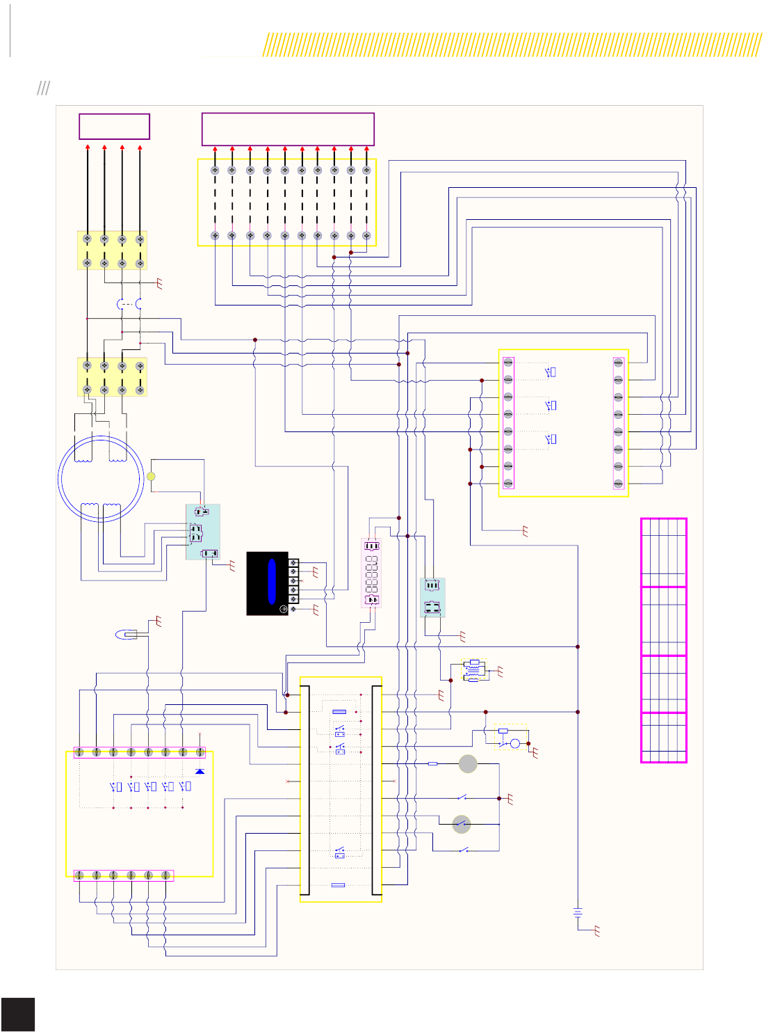
WIRING DIAGRAM
F.D2
Low Oil Level/Pressure
High Engine Temperature
Exercise
ATS
F.D1
Motor
1
2
3
5
7
8
9
10
100666
6
4
DC 24V
B+
B-
11
12
14
13
5A 5A
Valve
5A
Alarm
5A
Stop
5A
Magnetize
Charge
Freq. Freq. ATS IN.1 WATROILALTFUEL Start Stop B+ B-
Freq. Freq. ATS IN.1 WATROILALTFUEL Start Stop B+ B-
100417
250VAC 5A
40A
1
2
3
5
7
8
9
10
100667
6
4
DC 24V
5A
5A5A
B+
B-
B-
Start ATS
Gen-set Close
Gen-set Close
Gen-set C.B
Utility C.B.
Utility Close
Utility Close
11 Utility AC Detect
12 Utility AC Detect
14 Load AC Detect
13 Load AC Detect
16 Gen-A C Detect
15 Gen-A C Detect
24V
Battery
GND
GND
Fuel Valve
Fuel Valve
GND
GND
M
Start Motor
GND
Iginition Coil
GND
GND
To ATS
Transfer common
Generator transfer signal
Generator position micro sw itch
Utility transfer signal
Micro switch common
5
12
11
6
2
1
3
10
9
7
Utility line L2
Utility line L1
Utility position micro sw itch
Load bus L2
Load bus L1
Neutral line
Indicator Light DC24V
L N
BATTERY CHARGER
MODEL:100482
-+
GND
N/C
GND
Circuit Breaker
N/C
N/C
50W10Ω Power Resistance
GND
+
-
L1
L2
Hour Meter
44
33
22
11
STATOR
Power Winding
Power Winding
Excitation Winding
Sampling Winding
Carbon Brush
ROTOR
CB
To ATS
Terminal Block #1 Terminal Block #2
AVR
+
-
Over Voltage Protector
GND
GND
R
R
B
Br
O/B
Y
OG/B
B/W
L/B
R/B
L
W
G
BBr
O/B Y
OG/B B/W L/B WG
G
B
R
R
R G G
R
R
RG B
W
G
O
B R
L
G/B P BrY
B/W
Pu O
O
Pu
B/W
Br
P
Y
G/B
L
G
W
R
B
W
B
R
P
R
B
B R
G
Y
W
L
L
G
L/B
G
W
R
R
B
Br
Y
Red
Black
Brown
L
Yellow
Blue
G
O
W
P
Green
Orange
White
Pu
Pink
Purple
O/B
G/B
R/B
B/W
Orange/Black
Green/Black
L/B
Red/Black
Black/White
Blue/Black
W
Terminal Block #3
Not Connect
N/C
Low Oil Level/Pressure Switch
G
Thermal Switch
G
Exercise Switch
G
G
+-
LLWG
Br
G
PART NO:100199.21.V1.1
N/C
Ground line
Generator line L2
Generator line L1
Model 100199
TROUBLESHOOTING
35
© 2015 Champion Power Equipment Part No. 101048
Before performing troubleshooting procedures, review SAFETY
section starting on page 5.
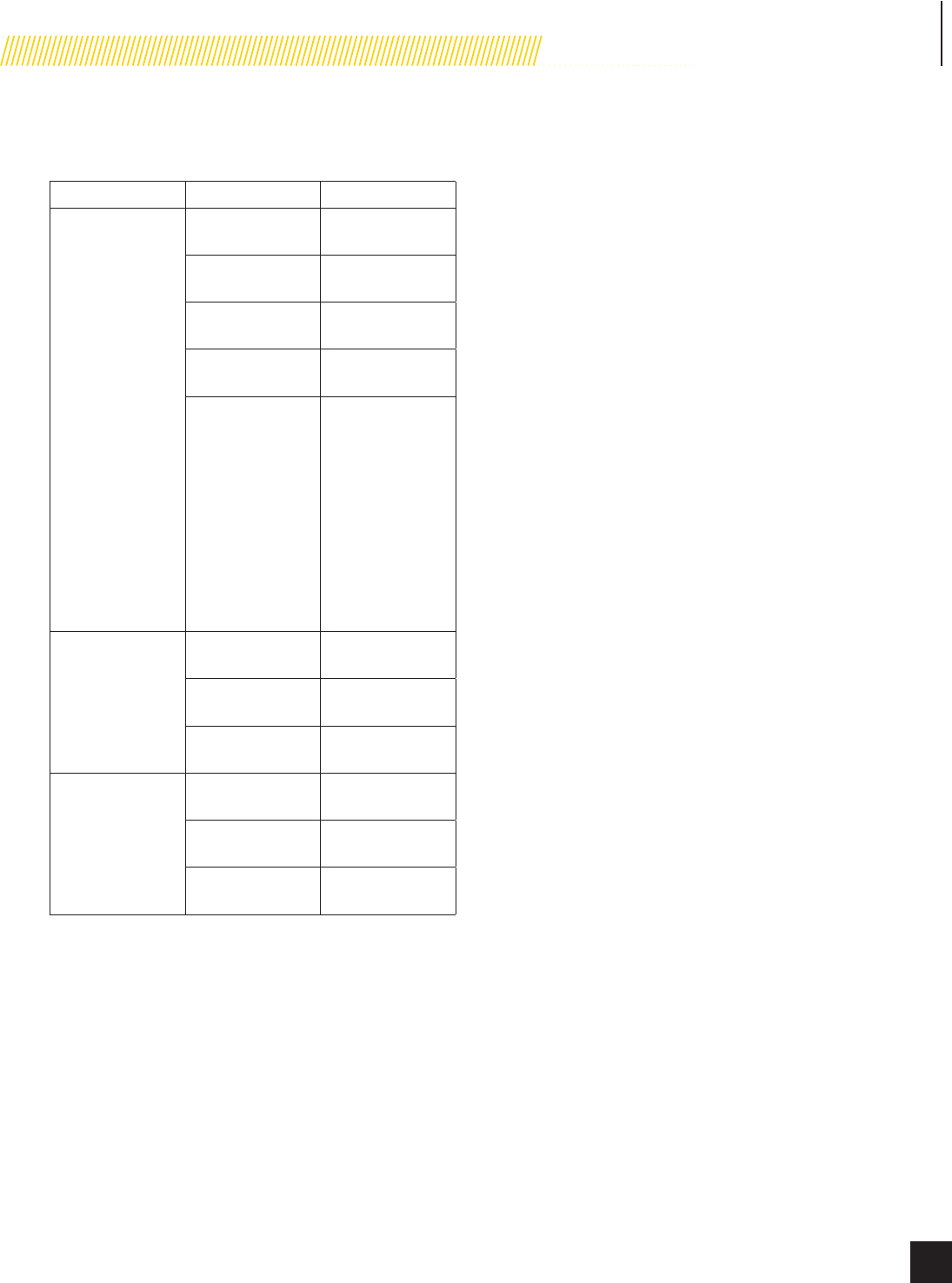
Problem Cause Solution
Generator will not
start
Fuel valve turned
off
Turn fuel valve on.
Battery not
charged
Charge battery.
Faulty spark plug Replace spark
plug.
Engine control
module switch off
Turn switch to ATS
or manual.
Active fault code Check fault codes.
Determine what
the fault code is
and remedy the
situation or have
the generator
serviced by
an authorized
Service Dealer or
contact Champion
Customer Service.
Generator starts
but runs rough
Faulty spark plug Replace spark
plug.
Plugged air cleaner Clean or replace
air cleaner.
Fuel pressure
incorrect
Contact authorized
service dealer.
No generator
output
ATS control module
switch off
Turn switch to
auto.
Main circuit
breaker is off
Turn breaker to on.
Transfer switch
turned off
Turn transfer
switch on.
Champion Power Equipment
Toll-free: 1-877-338-0999
Mon-Fri 8:30 AM – 5:00 PM (PST/PDT)
Champion Power Equipment, Inc. (CPE),
United States Environment Protection Agency (U.S. EPA) and Environment Canada (EC)
Emission Control System Warranty
Your Champion Power Equipment (CPE) engine complies with U.S. EPA and EC emission regulations.
YOUR WARRANTY RIGHTS AND OBLIGATIONS:
The US EPA, EC AND CPE are pleased to explain the Federal Emission Control Systems Warranty on your 2015
small off-road engine and engine powered equipment. New engines and equipment must be designed, built and
equipped, at the time of sale, to meet U.S. EPA regulations for small non-road engines. CPE warrants the emission
control system on your small off-road engine and equipment for the period of time listed below, provided there has
been no abuse, neglect, unapproved modification, or improper maintenance of your equipment.
Your emission control system may include parts such as the carburetor, fuel-injection system, the ignition system,
catalytic converter and fuel lines. Also included may be hoses, belts, connectors and other emission related
assemblies. Where a warrantable condition exits, CPE will repair your small off-road engine at no cost to you
including diagnosis, parts and labor.
MANUFACTURER’S EMISSION CONTROL SYSTEM WARRANTY COVERAGE:
This emission control system is warranted for two years, subject to provisions set forth below. If, during the
warranty period, emission related part on your engine is defective in materials or workmanship, the part will be
repaired or replaced by CPE.
OWNER WARRANTY RESPONSIBILITIES:
As the small off-road engine owner, you are responsible for the performance of the required maintenance listed in
your Owner’s Manual. CPE recommends that you retain all your receipts covering maintenance on your small off-
road engine, but CPE cannot deny warranty solely for the lack of receipts or for your failure to ensure the
performance of all scheduled maintenance.
As the small off-road engine owner, you should however be aware that CPE may deny you warranty coverage if
your small, off-road engine or a part has failed due to abuse, neglect, improper maintenance or unapproved
modifications.
You are responsible for presenting your small off-road engine to an Authorized CPE service outlet or alternate
service outlet as described in (3)(f.) below, CPE dealer or CPE, Santa Fe Springs, Ca. as soon as a problem exists.
The warranty repairs should be completed in a reasonable amount of time, not to exceed 30 days.
If you have any questions regarding your warranty rights and responsibilities, you should contact:
Champion Power Equipment, Inc.
Customer Service
12039 Smith Ave.
Santa Fe Springs, CA 90670
1-877-338-0999
tech@championpowerequipment.com
EMISSION CONTROL SYSTEM WARRANTY
The following are specific provisions relative to your Emission Control System (ECS) Warranty Coverage.
1. APPLICABILITY: This warranty shall apply to 1997 and later model year small off-road engines. The ECS
Warranty Period shall begin on the date the new engine or equipment is delivered to its original, end-use
purchaser, and shall continue for 24 consecutive months thereafter.
2. GENERAL EMISSIONS WARRANTY COVERAGE
CPE warrants to the original, end-use purchaser of the new engine or equipment and to each subsequent
purchaser that each of its small off-road engines is:
a. Designed, built and equipped so as to conform to U.S. EPA emissions standards for spark-ignited
engines at or below 19 kilowatts.
b. Free from defects in materials and workmanship that cause the failure of a warranted part to be identical
in all material respects to the part as described in the engine manufacturer’s application for certification for a period
of two years.
3. THE WARRANTY ON EMISSION-RELATED PARTS WILL BE INTERPRETED AS FOLLOWS:
a. Any warranted part that is not scheduled for replacement as required maintenance in the Owners
Manual shall be warranted for the ECS Warranty Period. If any such part fails during the ECS Warranty Period, it
shall be repaired or replaced by CPE according to Subsection “d” below. Any such part repaired or replaced under
the ECS Warranty shall be warranted for any remainder of the ECS Warranty Period.
b. Any warranted, emissions-related part which is scheduled only for regular inspection as specified in the
Owners Manual shall be warranted for the ECS Warranty Period. A statement in such written instructions to the
effect of “repair or replace as necessary”, shall not reduce the ECS Warranty Period. Any such part repaired or
replaced under the ECS Warranty shall be warranted for the remainder of the ECS Warranty Period.
c. Any warranted, emissions-related part which is scheduled for replacement as required maintenance in
the Owner’s Manual shall be warranted for the period of time prior to the first scheduled replacement point for that
part. If the part fails prior to the first scheduled replacement, the part shall be repaired or replaced by CPE
according to Subsection “d” below. Any such emissions-related part repaired or replaced under the ECS Warranty,
shall be warranted for the remainder of the ECS Warranty Period prior to the first scheduled replacement point for
such emissions-related part.
d. Repair or replacement of any warranted, emissions-related part under this ECS Warranty shall be
performed at no charge to the owner at a CPE Authorized Service Outlet.
e. The owner shall not be charged for diagnostic labor which leads to the determination that a part covered
by the ECS Warranty is in fact defective, provided that such diagnostic work is performed at a CPE Authorized
Service Outlet.
f. CPE shall pay for covered emissions warranty repairs at non-authorized service outlets under the
following circumstances:
i. The service is required in a population center with a population over 100,000 according to U.S.
Census 2000 without a CPE Authorized Service Outlet AND
ii. The service is required more than 100 miles from a CPE Authorized Service Outlet. The 100 mile
limitation does not apply in the following states: Alaska, Arizona, Colorado, Hawaii, Idaho, Montana, Nebraska,
Nevada, New Mexico, Oregon, Texas, Utah and Wyoming.
g. CPE shall be liable for damages to other original engine components or approved modifications
proximately caused by a failure under warranty of an emission-related part covered by the ECS Warranty.
h. Throughout the ECS Warranty Period, CPE shall maintain a supply of warranted emission-related parts
sufficient to meet the expected demand for such emission-related parts.
i. Any CPE Authorized and approved emission-related replacement part may be used in the performance of
any ECS Warranty maintenance or repair and will be provided without charge to the owner. Such use shall not
reduce CPE’s warranty obligation.
j. Unapproved add-on or modified parts may not be used to modify or repair a CPE engine. Such use voids
this ECS Warranty and shall be sufficient grounds for disallowing an ECS Warranty claim. CPE shall not be liable
hereunder for failures of any warranted parts of a CPE engine caused by the use of such an unapproved add-on or
modified part.

EMISSION-RELATED PARTS INCLUDE THE FOLLOWING: (using those portions of the list applicable to the
engine)
Systems covered by this
warranty
Parts Description
Fuel Metering System
Fuel regulator, Carburetor and internal parts
Air Induction System
Air cleaner, Intake manifold
Ignition System
Spark plug and parts, Magneto ignition system
Exhaust System
Exhaust manifold, catalytic converter
Miscellaneous Parts
Tubing, Fittings, Seals, Gaskets, and Clamps associated with these listed
systems.
Evaporative Emissions
Fuel Tank, Fuel Cap, Fuel Line, Fuel Line Fittings, Clamps, Pressure
Relief Valves, Control Valves, Control Solenoids, Electronic Controls,
Vacuum Control Diaphragms, Control Cables, Control Linkages, Purge
Valves, Vapor Hoses, Liquid/Vapor Separator, Carbon Canister, Canister
Mounting Brackets, Carburetor Purge Port Connector
TO OBTAIN WARRANTY SERVICE:
You must take your CPE engine or the product on which it is installed, along with your warranty registration card or
other proof of original purchase date, at your expense, to any Champion Power Equipment dealer who is
authorized by Champion Power Equipment, Inc. to sell and service that CPE product during his normal business
hours. Alternate service locations defined in Section (3)(f.) above must be approved by CPE prior to service. Claims
for repair or adjustment found to be caused solely by defects in material or workmanship will not be denied because
the engine was not properly maintained and used.
If you have any questions regarding your warranty rights and responsibilities, or to obtain warranty
service, please write or call Customer Service at Champion Power Equipment, Inc.
Champion Power Equipment, Inc.
12039 Smith Ave.
Santa Fe Springs, CA 90670
1-877-338-0999
Attn.: Customer Service
tech@championpowerequipment.com

Champion Power Equipment
12039 Smith Ave.
Santa Fe Springs, CA 90670 USA
Made in China
