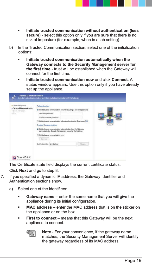
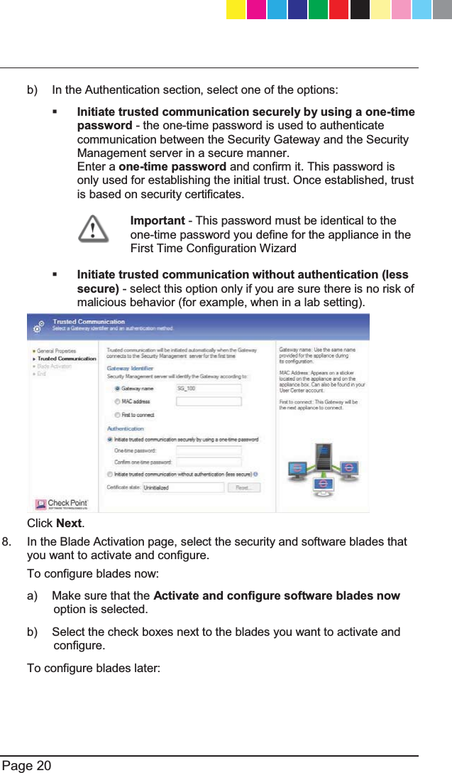
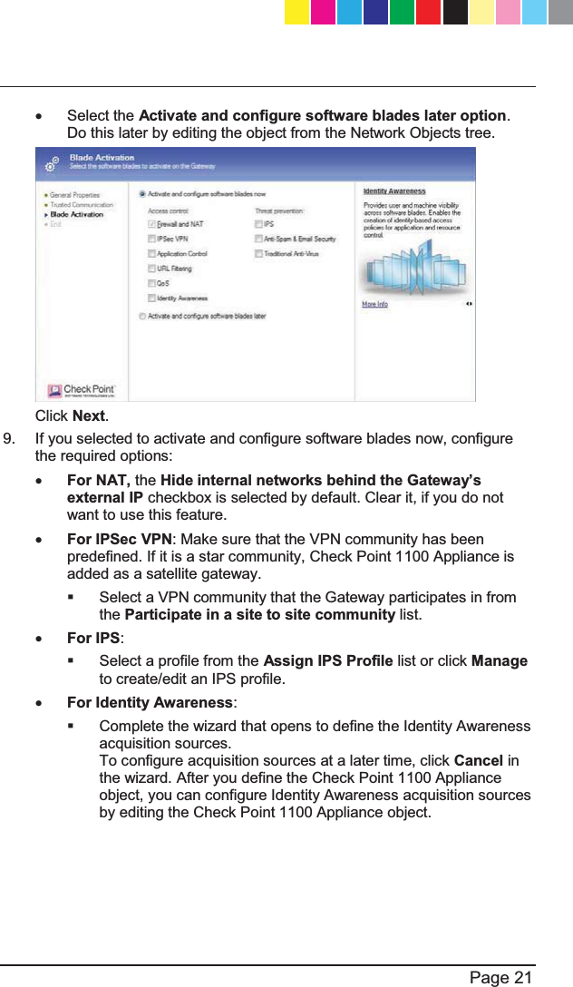
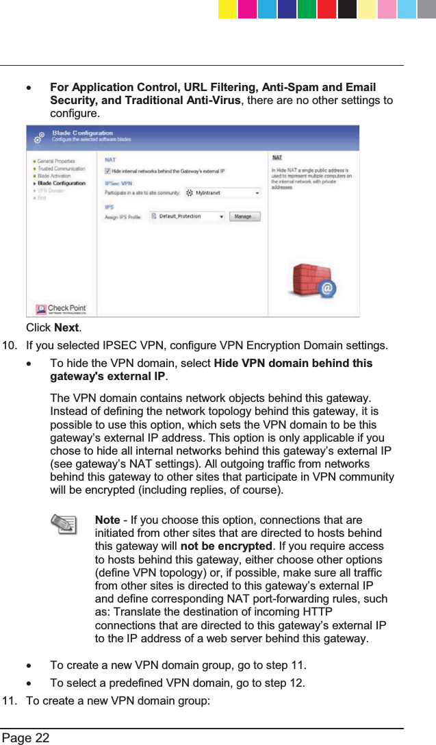
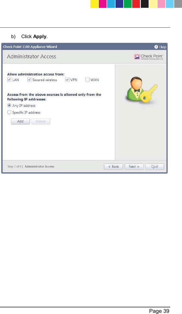
Check Point Software technologies 67897 SG-80A Security Gateway 80 User Manual CP 1100Appliance GettingStartedGuide dvd
Check Point Software technologies Ltd, SG-80A Security Gateway 80 CP 1100Appliance GettingStartedGuide dvd
L-50WD User Manual Revised 0503
![25 February 2013 Getting Started GuideCheck Point 1100 Appliance Centrally Managed SG-80A Models: L-50, L-50D, L-50W, L-50WD Classification: [Protected] P/N 705188 CP_1100Appliance_GettingStartedG1 1CP_1100Appliance_GettingStartedG1 1 25/02/2013 10:05:2925/02/2013 10:05:29SG-80A Models:L-50W;L-50WD;L-50xxxxx(x= 0~9, A~Z, Blank or any Character)](https://usermanual.wiki/Check-Point-Software-technologies/67897/User-Guide-1956592-Page-1.png)
![Page 12 Shipping Carton Contents This section describes the contents of the shipping carton. Contents of the Shipping Carton Item Description Appliance A single Check Point 1100 Appliance Power Supply and Cables x 1 power supply unit x 1 standard network cable x 1 serial console cable x 1 telephone cable (only in ADSL models) Guides x Check Point 1100 Appliance Quick Start Guide x Check Point 1100 Appliance Getting Started Guide Wireless Network Antennas x A pair of wireless network antennas (only in wireless network models) Sticker x LEDs behavior License Agreement x End User License Agreement Glossary The following Check Point 1100 Appliance terms are used throughout this guide: x Security Gateway - 7KHVHFXULW\HQJLQHWKDWHQIRUFHVWKHRUJDQL]DWLRQ¶Vsecurity policy and acts as a security enforcement point. The Security Gateway is managed by the Security Management server and sits on the network as an entry point to the LAN. x Security Policy - The policy created by the system administrator that regulates the flow of incoming and outgoing communication. CP_1100Appliance_GettingStartedG12 12CP_1100Appliance_GettingStartedG12 12 25/02/2013 10:05:3025/02/2013 10:05:30](https://usermanual.wiki/Check-Point-Software-technologies/67897/User-Guide-1956592-Page-12.png)
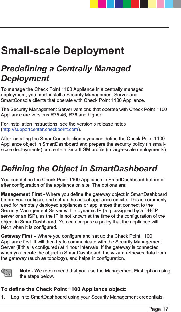
![Page 13 x Security Management server - The server used by the system DGPLQLVWUDWRUWRPDQDJHWKHVHFXULW\SROLF\7KHRUJDQL]DWLRQ¶VGDWDEDVHVand security policies are stored on the Security Management server and downloaded to the Security Gateway. x SmartConsole - GUI applications that are used to manage various aspects of security policy enforcement. For example, SmartView Tracker is a SmartConsole application that manages logs. x SmartDashboard - A SmartConsole GUI application that is used by the system administrator to create and manage the security policy. Check Point 1100 Appliance Overview Check Point's Check Point 1100 Appliance delivers integrated unified threat management to protect your organization from today's emerging threats. Based on proven Check Point security technologies such as Stateful Inspection, Application Intelligence, and SMART (Security Management Architecture), Check Point 1100 Appliance provides simplified deployment while delivering uncompromising levels of security. Check Point 1100 Appliance supports the Check Point Software Blade architecture, providing independent, modular and centrally managed security building blocks. Software Blades can be quickly enabled and configured into a solution based on specific security needs. Check Point 1100 Appliance can be centrally managed by a remote Security Management Server or locally managed by a Web user interface (WebUI). Security Gateway Software Blades These Software Blades are included in Check Point 1100 Appliance: x Firewall - :RUOG¶VPRVWSURYHQILUHZDOOVROXWLRQWKDWFDQH[DPLQHhundreds of applications, protocols and services out-of-the box. The firewall also performs Network Address Translation and intelligent VoIP security. CP_1100Appliance_GettingStartedG13 13CP_1100Appliance_GettingStartedG13 13 25/02/2013 10:05:3025/02/2013 10:05:30](https://usermanual.wiki/Check-Point-Software-technologies/67897/User-Guide-1956592-Page-13.png)
![Page 14 x IPSec VPN - Sophisticated (but simple to manage) Site-to-Site VPN and flexible Remote Access working seamlessly with a variety of VPN agents. x Application Control - Signature-based granular control of thousands of Internet applications and Web 2.0 widgets. x URL Filtering - Best of breed URL filtering engine, based on a central database, located in the Check Point data center. This ensures excellent coverage of URLs, while maintaining minimal footprints on devices. Check Point 1100 Appliance provides cut-through performance, as URL categorization queries are done asynchronously. x Identity Awareness - Gives user and machine visibility across network blades. Enables the creation of identity-based access policies for application and resource control. x IPS (More than 2000 protections) - Best in class integrated IPS with leading performance and unlimited scaling. IPS protections are updated with IPS updates. x Anti-spam & Email Security (based on IP Reputation and content) - &RPSUHKHQVLYHDQGPXOWLGLPHQVLRQDOSURWHFWLRQIRURUJDQL]DWLRQV¶HPDLOinfrastructure. This includes updates. x Traditional Anti-Virus - Leading Anti-virus protection using state-of-the-art Anti-virus engine by Kaspersky. The Anti-virus engine runs in stream (network) mode, supporting high performance and concurrency. x Advanced Networking and Clustering - For dynamic routing and Multicast support. Wire speed packet inspection with SecureXL and high availability or load sharing with ClusterXL. x QoS - Quality of Service optimizes network performance by prioritizing business-critical applications and end-user traffic. It guarantees bandwidth and control latency for streaming applications, such as VoIP and video conferencing. This Getting Started Guide Includes: x A brief overview of essential Check Point 1100 Appliance concepts and features. x A step by step guide to getting Check Point 1100 Appliance up and running. CP_1100Appliance_GettingStartedG14 14CP_1100Appliance_GettingStartedG14 14 25/02/2013 10:05:3025/02/2013 10:05:30](https://usermanual.wiki/Check-Point-Software-technologies/67897/User-Guide-1956592-Page-14.png)


![P Predefining a Centrally Managed Deployment Preparing to Install the 6HFXULW\3ROLF\ R Recommended Workflow Restoring Factory 'HIDXOWV S Security Gateway 6RIWZDUH%ODGHV Security Policy 0DQDJHPHQW Setting Up the Check 3RLQW$SSOLDQFH26 Shipping Carton &RQWHQWV Small-scale Deployment Starting the First Time &RQILJXUDWLRQ:L]DUG27 6XPPDU\ 6XSSRUW Support and Further ,QIRUPDWLRQ T This Getting Started Guide Includes U Using the First Time &RQILJXUDWLRQ:L]DUG27 V Viewing the Policy ,QVWDOODWLRQ6WDWXV W :HOFRPH :KHUH7R)URP+HUH"55 Wireless Network (for Wireless Network 0RGHOV CP_1100Appliance_GettingStartedG68 68CP_1100Appliance_GettingStartedG68 68 25/02/2013 10:05:3125/02/2013 10:05:31](https://usermanual.wiki/Check-Point-Software-technologies/67897/User-Guide-1956592-Page-68.png)