Check Point Software technologies 67897 SG-80A Security Gateway 80 User Manual CP 1100Appliance GettingStartedGuide dvd
Check Point Software technologies Ltd, SG-80A Security Gateway 80 CP 1100Appliance GettingStartedGuide dvd
L-50WD User Manual Revised 0503

25 February 2013
Getting Started Guide
Check Point 1100
Appliance
Centrally Managed
SG-80A Models: L-50, L-50D, L-50W, L-50WD
Classification: [Protected] P/N 705188
CP_1100Appliance_GettingStartedG1 1CP_1100Appliance_GettingStartedG1 1 25/02/2013 10:05:2925/02/2013 10:05:29
SG-80A Models:L-50W;L-50WD;L-50xxxxx(x= 0~9, A~Z, Blank or any Character)

Page 2
© 2013 Check Point Software Technologies Ltd.
All rights reserved. This product and related documentation are protected by
copyright and distributed under licensing restricting their use, copying,
distribution, and decompilation. No part of this product or related
documentation may be reproduced in any form or by any means without prior
written authorization of Check Point. While every precaution has been taken in
the preparation of this book, Check Point assumes no responsibility for errors
or omissions. This publication and features described herein are subject to
change without notice.
RESTRICTED RIGHTS LEGEND:
Use, duplication, or disclosure by the government is subject to restrictions as
set forth in subparagraph (c)(1)(ii) of the Rights in Technical Data and
Computer Software clause at DFARS 252.227-7013 and FAR 52.227-19.
TRADEMARKS:
Refer to the Copyright page (http://www.checkpoint.com/copyright.html) for a
list of our trademarks.
Refer to the Third Party copyright notices
(http://www.checkpoint.com/3rd_party_copyright.html) for a list of relevant
copyrights and third-party licenses.
CP_1100Appliance_GettingStartedG2 2CP_1100Appliance_GettingStartedG2 2 25/02/2013 10:05:2925/02/2013 10:05:29

Page 3
Latest Documentation
The latest version of this document is at:
http://supportcontent.checkpoint.com/documentation_download?ID=22711
For additional technical information, visit the Check Point Support Center
(http://supportcenter.checkpoint.com).
Feedback
Check Point is engaged in a continuous effort to improve its documentation.
Please help us by sending your comments
(mailto:cp_techpub_feedback@checkpoint.com?subject=Feedback on Check
Point 1100 Appliance Centrally Managed Getting Started Guide).
CP_1100Appliance_GettingStartedG3 3CP_1100Appliance_GettingStartedG3 3 25/02/2013 10:05:2925/02/2013 10:05:29
Page 4
Health and Safety
Information
Read the following warnings before setting up or using the appliance.
Warning - Do not block air vents. A minimum 1/2-inch
clearance is required.
Warning - This appliance does not contain any user-
serviceable parts. Do not remove any covers or attempt to gain
access to the inside of the product. Opening the device or
modifying it in any way has the risk of personal injury and will
void your warranty. The following instructions are for trained
service personnel only.
To prevent damage to any system board, it is important to handle it with care.
The following measures are generally sufficient to protect your equipment from
static electricity discharge:
x When handling the board, use a grounded wrist strap designed for static
discharge elimination.
x Touch a grounded metal object before removing the board from the
antistatic bag.
x Handle the board by its edges only. Do not touch its components,
peripheral chips, memory modules or gold contacts.
x When handling processor chips or memory modules, avoid touching their
pins or gold edge fingers.
x Restore the communications appliance system board and peripherals
back into the antistatic bag when they are not in use or not installed in the
chassis. Some circuitry on the system board can continue operating even
though the power is switched off.
x Under no circumstances should the lithium battery cell used to power the
real-time clock be allowed to short. The battery cell may heat up under
these conditions and present a burn hazard.
CP_1100Appliance_GettingStartedG4 4CP_1100Appliance_GettingStartedG4 4 25/02/2013 10:05:2925/02/2013 10:05:29

Page 5
Warning - DANGER OF EXPLOSION IF BATTERY IS
INCORRECTLY REPLACED. REPLACE ONLY WITH SAME
OR EQUIVALENT TYPE RECOMMENDED BY THE
MANUFACTURER. DISCARD USED BATTERIES
$&&25',1*727+(0$18)$&785(5¶6,16758&7,216
x Do not dispose of batteries in a fire or with household waste.
x Contact your local waste disposal agency for the address of the nearest
battery deposit site.
x Disconnect the system board power supply from its power source before
you connect or disconnect cables or install or remove any system board
components. Failure to do this can result in personnel injury or equipment
damage.
x Avoid short-circuiting the lithium battery; this can cause it to superheat
and cause burns if touched.
x Do not operate the processor without a thermal solution. Damage to the
processor can occur in seconds.
For California:
Perchlorate Material - special handling may apply. See
http://www.dtsc.ca.gov/hazardouswaste/perchlorate
The foregoing notice is provided in accordance with California Code of
Regulations Title 22, Division 4.5, Chapter 33. Best Management Practices for
Perchlorate Materials. This product, part, or both may include a lithium
manganese dioxide battery which contains a perchlorate substance.
Proposition 65 Chemical
Chemicals identified by the State of California, pursuant to the requirements of
the California Safe Drinking Water and Toxic Enforcement Act of 1986,
California Health & Safety Code s. 25249.5, et seq. ("Proposition 65"), that is
"known to the State to cause cancer or reproductive toxicity" (see
http://www.calepa.ca.gov)
WARNING:
Handling the cord on this product will expose you to lead, a chemical known to
the State of California to cause cancer, and birth defects or other reproductive
harm. Wash hands after handling.
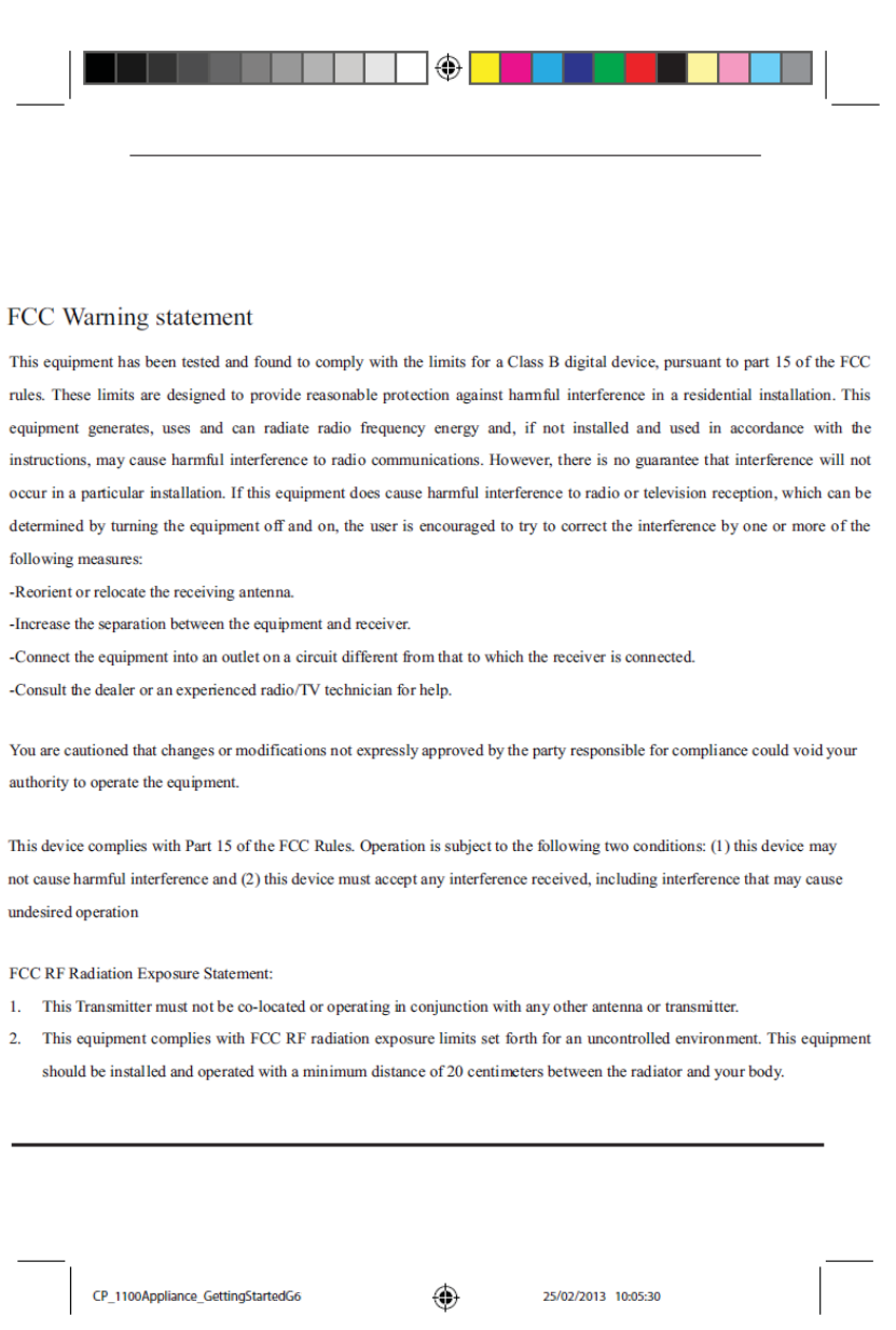
Federal Communications Commission (FCC) Statement:
This equipment has been tested and found to comply with the limits for a Class
B digital device, pursuant to Part 15 of the FCC Rules. These limits are
CP_1100Appliance_GettingStartedG5 5CP_1100Appliance_GettingStartedG5 5 25/02/2013 10:05:2925/02/2013 10:05:29

Page 6
designed to provide reasonable protection against harmful interference in a
residential installation.
This equipment generates, uses and can radiate radio frequency energy and, if
not installed and used in accordance with the instructions, may cause harmful
interference to radio communications. However, there is no guarantee that
interference will not occur in a particular installation. If this equipment does
cause harmful interference to radio or television reception, which can be
determined by turning the equipment off and on, the user is encouraged to try
to correct the interference by one of the following measures:
x Reorient or relocate the receiving antenna.
x Increase the separation between the equipment and receiver.
x Connect the equipment into an outlet on a circuit different from that to
which the receiver is connected.
x Consult the dealer or an experienced radio/TV technician for help.
To assure continued compliance, any changes or modifications not expressly
approved by the party responsible for compliance could void the user's
authority to operate this equipment. (Example - use only shielded interface
cables when connecting to computer or peripheral devices).
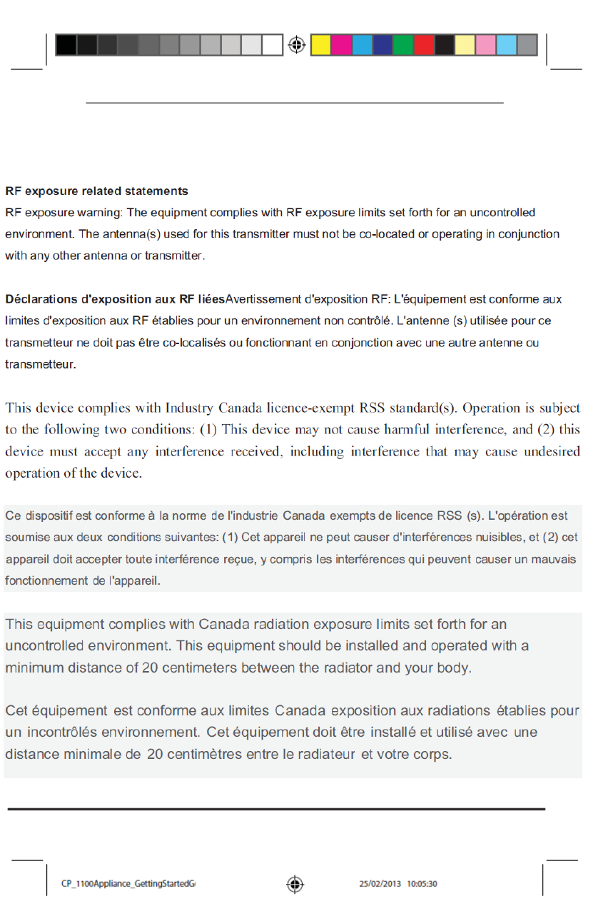
FCC Radiation Exposure Statement
This equipment complies with FCC RF radiation exposure limits set forth for an
uncontrolled environment. This equipment should be installed and operated
with a minimum distance of 20 centimeters between the radiator and your
body. This device complies with Part 15 of the FCC Rules. Operation is subject
to the following two conditions:
(1) This device may not cause harmful interference, and
(2) This device must accept any interference received, including interference
that may cause undesired operation.
This transmitter must not be co-located or operating in conjunction with any
other antenna or transmitter.
Canadian Department Compliance Statement
This device complies with Industry Canada ICES-003 and RSS210 rules. Cet
appareil est conforme aux normes N0%HW566G¶,QGXVWULH&DQDGD
CP_1100Appliance_GettingStartedG6 6CP_1100Appliance_GettingStartedG6 6 25/02/2013 10:05:2925/02/2013 10:05:29
Page 7
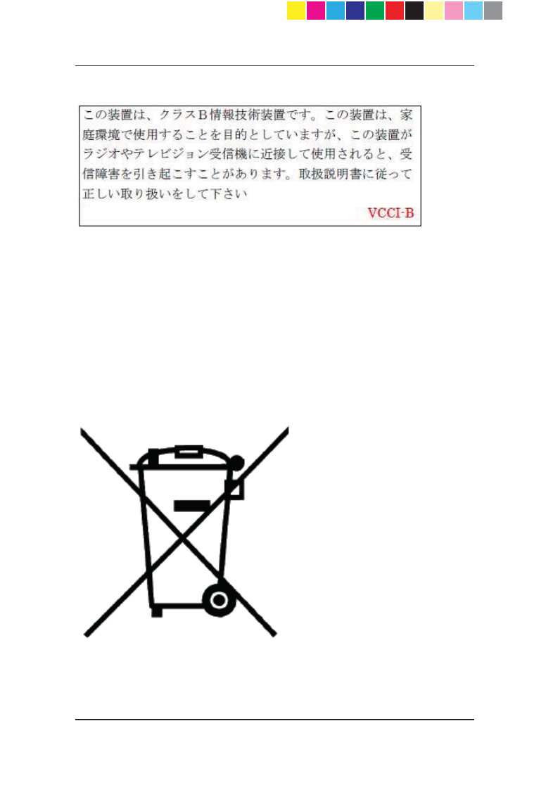
Japan Class B Compliance Statement:
European Union (EU) Electromagnetic Compatibility
Directive
This product is herewith confirmed to comply with the requirements set out in
the Council Directive on the Approximation of the Laws of the Member States
relating to Electromagnetic Compatibility Directive (2004/108/EC).
This product is in conformity with Low Voltage Directive 2006/95/EC, and
complies with the requirements in the Council Directive 2006/95/EC relating to
electrical equipment designed for use within certain voltage limits and the
Amendment Directive 93/68/EEC.
Product Disposal
This symbol on the product or on its packaging indicates that this product must
not be disposed of with your other household waste. Instead, it is your
responsibility to dispose of your waste equipment by handing it over to a
designated collection point for the recycling of waste electrical and electronic
CP_1100Appliance_GettingStartedG7 7CP_1100Appliance_GettingStartedG7 7 25/02/2013 10:05:2925/02/2013 10:05:29

Page 8
equipment. The separate collection and recycling of your waste equipment at
the time of disposal will help to conserve natural resources and ensure that it is
recycled in a manner that protects human health and the environment. For
more information about where you can drop off your waste equipment for
recycling, please contact your local city office or your household waste disposal
service.
CP_1100Appliance_GettingStartedG8 8CP_1100Appliance_GettingStartedG8 8 25/02/2013 10:05:2925/02/2013 10:05:29

Contents
Health and Safety Information ............................................ 4
Introduction ................................................................. 11
Welcome .......................................................................... 11
Shipping Carton Contents ................................................ 12
Glossary ........................................................................... 12
Check Point 1100 Appliance Overview ......................... 13
Security Gateway Software Blades .................................. 13
This Getting Started Guide Includes: ................................ 14
Configuring Check Point 1100 Appliance ..................... 15
Management Options ....................................................... 15
Recommended Workflow ................................................. 16
Small-scale Deployment ................................................... 17
Predefining a Centrally Managed Deployment ................ 17
Defining the Object in SmartDashboard ........................... 17
Preparing to Install the Security Policy ............................. 24
Setting Up the Check Point 1100 Appliance .................... 26
Connecting the Cables ........................................................ 26
Using the First Time Configuration Wizard ...................... 27
Large-scale Deployment ................................................... 46
Predefining a Centrally Managed Deployment ................ 46
Defining a SmartLSM Profile .............................................. 46
Deploying with SmartProvisioning ..................................... 47
Check Point 1100 Appliance Hardware ......................... 49
CP_1100Appliance_GettingStartedG9 9CP_1100Appliance_GettingStartedG9 9 25/02/2013 10:05:3025/02/2013 10:05:30

Front Panel ....................................................................... 50
Back Panel ....................................................................... 52
Restoring Factory Defaults .......................................... 54
Support and Further Information .................................. 57
Support ............................................................................. 57
Where To From Here? ...................................................... 57
Appendix A: Browser Security Warnings ..................... 59
Appendix B: Security Management Issues ................... 61
Viewing the Policy Installation Status ............................... 61
Configuring Notification Settings ....................................... 65
Index ............................................................................ 67
CP_1100Appliance_GettingStartedG10 10CP_1100Appliance_GettingStartedG10 10 25/02/2013 10:05:3025/02/2013 10:05:30

Page 11
Chapter 1
Introduction
In This Chapter
Welcome
Shipping Carton Contents
Glossary
Important - Before reading this Getting Started Guide, make
sure that you have read and understood the information in the
YHUVLRQ¶Vrelease notes (http://supportcenter.checkpoint.com) and
the Check Point 1100 Appliance Known Limitations
SecureKnowledge article
(http://supportcontent.checkpoint.com/solutions?id=sk90342).
Welcome
Thank you for choosing Check Point's Internet Security Product Suite. We
hope that you will be satisfied with this solution and our support services.
Check Point products provide your business with the most up to date and
secure solutions available today.
Check Point also delivers worldwide technical services including educational,
professional and support services through a network of Authorized Training
Centers, Certified Support Partners and Check Point technical support
personnel to ensure that you get the most out of your security investment.
For additional information on the Check Point Internet Security Product Suite
and other security solutions, refer to: http://www.checkpoint.com
(http://www.checkpoint.com). For technical assistance, contact Check Point 24
hours a day, seven days a week at:+1 972-444-6600 (Americas) +972 3-611-
5100 (International). For additional technical information, refer to:
http://support.checkpoint.com (http://supportcenter.checkpoint.com).
Welcome to the Check Point family. We look forward to meeting all of your
current and future network, application and management security needs.
CP_1100Appliance_GettingStartedG11 11CP_1100Appliance_GettingStartedG11 11 25/02/2013 10:05:3025/02/2013 10:05:30

Page 12
Shipping Carton Contents
This section describes the contents of the shipping carton.
Contents of the Shipping Carton
Item Description
Appliance A single Check Point 1100 Appliance
Power Supply and Cables
x 1 power supply unit
x 1 standard network cable
x 1 serial console cable
x 1 telephone cable (only in ADSL
models)
Guides
x Check Point 1100 Appliance
Quick Start Guide
x Check Point 1100 Appliance
Getting Started Guide
Wireless Network Antennas
x A pair of wireless network
antennas (only in wireless network
models)
Sticker
x LEDs behavior
License Agreement
x End User License Agreement
Glossary
The following Check Point 1100 Appliance terms are used throughout this
guide:
x Security Gateway - 7KHVHFXULW\HQJLQHWKDWHQIRUFHVWKHRUJDQL]DWLRQ¶V
security policy and acts as a security enforcement point. The Security
Gateway is managed by the Security Management server and sits on the
network as an entry point to the LAN.
x Security Policy - The policy created by the system administrator that
regulates the flow of incoming and outgoing communication.
CP_1100Appliance_GettingStartedG12 12CP_1100Appliance_GettingStartedG12 12 25/02/2013 10:05:3025/02/2013 10:05:30

Page 13
x Security Management server - The server used by the system
DGPLQLVWUDWRUWRPDQDJHWKHVHFXULW\SROLF\7KHRUJDQL]DWLRQ¶VGDWDEDVHV
and security policies are stored on the Security Management server and
downloaded to the Security Gateway.
x SmartConsole - GUI applications that are used to manage various
aspects of security policy enforcement. For example, SmartView Tracker
is a SmartConsole application that manages logs.
x SmartDashboard - A SmartConsole GUI application that is used by the
system administrator to create and manage the security policy.
Check Point 1100
Appliance Overview
Check Point's Check Point 1100 Appliance delivers integrated unified threat
management to protect your organization from today's emerging threats.
Based on proven Check Point security technologies such as Stateful
Inspection, Application Intelligence, and SMART (Security Management
Architecture), Check Point 1100 Appliance provides simplified deployment
while delivering uncompromising levels of security.
Check Point 1100 Appliance supports the Check Point Software Blade
architecture, providing independent, modular and centrally managed security
building blocks. Software Blades can be quickly enabled and configured into a
solution based on specific security needs.
Check Point 1100 Appliance can be centrally managed by a remote Security
Management Server or locally managed by a Web user interface (WebUI).
Security Gateway Software
Blades
These Software Blades are included in Check Point 1100 Appliance:
x Firewall - :RUOG¶VPRVWSURYHQILUHZDOOVROXWLRQWKDWFDQH[DPLQH
hundreds of applications, protocols and services out-of-the box. The
firewall also performs Network Address Translation and intelligent VoIP
security.
CP_1100Appliance_GettingStartedG13 13CP_1100Appliance_GettingStartedG13 13 25/02/2013 10:05:3025/02/2013 10:05:30

Page 14
x IPSec VPN - Sophisticated (but simple to manage) Site-to-Site VPN and
flexible Remote Access working seamlessly with a variety of VPN agents.
x Application Control - Signature-based granular control of thousands of
Internet applications and Web 2.0 widgets.
x URL Filtering - Best of breed URL filtering engine, based on a central
database, located in the Check Point data center. This ensures excellent
coverage of URLs, while maintaining minimal footprints on devices. Check
Point 1100 Appliance provides cut-through performance, as URL
categorization queries are done asynchronously.
x Identity Awareness - Gives user and machine visibility across network
blades. Enables the creation of identity-based access policies for
application and resource control.
x IPS (More than 2000 protections) - Best in class integrated IPS with
leading performance and unlimited scaling. IPS protections are updated
with IPS updates.
x Anti-spam & Email Security (based on IP Reputation and content) -
&RPSUHKHQVLYHDQGPXOWLGLPHQVLRQDOSURWHFWLRQIRURUJDQL]DWLRQV¶HPDLO
infrastructure. This includes updates.
x Traditional Anti-Virus - Leading Anti-virus protection using state-of-the-
art Anti-virus engine by Kaspersky. The Anti-virus engine runs in stream
(network) mode, supporting high performance and concurrency.
x Advanced Networking and Clustering - For dynamic routing and
Multicast support. Wire speed packet inspection with SecureXL and high
availability or load sharing with ClusterXL.
x QoS - Quality of Service optimizes network performance by prioritizing
business-critical applications and end-user traffic. It guarantees bandwidth
and control latency for streaming applications, such as VoIP and video
conferencing.
This Getting Started Guide
Includes:
x A brief overview of essential Check Point 1100 Appliance concepts and
features.
x A step by step guide to getting Check Point 1100 Appliance up and
running.
CP_1100Appliance_GettingStartedG14 14CP_1100Appliance_GettingStartedG14 14 25/02/2013 10:05:3025/02/2013 10:05:30

Page 15
Chapter 2
Configuring Check Point
1100 Appliance
In This Chapter
Management Options
Recommended Workflow
Small-scale Deployment
Large-scale Deployment
Management Options
Check Point 1100 Appliance can be managed centrally or locally.
x Central Management - The appliance is only a Security Gateway. A
remote Security Management server manages the Security Gateway in
SmartDashboard with a network object and security policy. We
recommend that you define a gateway object and prepare the policy
before you configure the appliance with the First Time Configuration
Wizard.
x Local Management - The appliance is a Security Gateway and uses a
web application to manage a Security Policy. After you configure the
appliance with the First Time Configuration Wizard, the default Security
Policy is enforced automatically. Using the WebUI, you can configure the
software blades you activated in the First Time Configuration Wizard and
fine tune the Security Policy.
This Getting Started Guide describes how to configure a centrally managed
deployment.
CP_1100Appliance_GettingStartedG15 15CP_1100Appliance_GettingStartedG15 15 25/02/2013 10:05:3025/02/2013 10:05:30

Page 16
Recommended Workflow
There are two types of centrally managed deployments:
x Small-scale deployment - Where you configure between 1 and 25 Check
Point 1100 Appliance gateways.
x Large-scale deployment - Where you configure over 25 Check Point
1100 Appliance gateways using a SmartLSM profile and
SmartProvisioning.
The recommended workflow for defining a small-scale deployment (on page
17) includes:
1. Installing a Security Management Server and SmartConsole clients that
operate with Check Point 1100 Appliance.
2. Defining the Check Point 1100 Appliance object in SmartDashboard and
preparing a policy for it.
3. Setting up the Check Point 1100 Appliance and connecting the cables.
4. Doing initial configuration of Check Point 1100 Appliance using the First
Time Configuration Wizard.
5. Optional: You can manage settings such as DNS, host names, and
routing through SmartProvisioning. For more information see the
SmartProvisioning Administration Guide.
The recommended workflow for defining a large-scale deployment (on page
46) includes:
1. Installing a Security Management Server and SmartConsole clients that
operate with Check Point 1100 Appliance.
2. Defining a SmartLSM profile in SmartDashboard.
3. Deploying with SmartProvisioning.
CP_1100Appliance_GettingStartedG16 16CP_1100Appliance_GettingStartedG16 16 25/02/2013 10:05:3025/02/2013 10:05:30

Page 17
Small-scale Deployment
Predefining a Centrally Managed
Deployment
To manage the Check Point 1100 Appliance in a centrally managed
deployment, you must install a Security Management Server and
SmartConsole clients that operate with Check Point 1100 Appliance.
The Security Management Server versions that operate with Check Point 1100
Appliance are versions R75.46, R76 and higher.
)RULQVWDOODWLRQLQVWUXFWLRQVVHHWKHYHUVLRQ¶Vrelease notes
(http://supportcenter.checkpoint.com).
After installing the SmartConsole clients you can define the Check Point 1100
Appliance object in SmartDashboard and prepare the security policy (in small-
scale deployments) or create a SmartLSM profile (in large-scale deployments).
Defining the Object in SmartDashboard
You can define the Check Point 1100 Appliance in SmartDashboard before or
after configuration of the appliance on site. The options are:
Management First - Where you define the gateway object in SmartDashboard
before you configure and set up the actual appliance on site. This is commonly
used for remotely deployed appliances or appliances that connect to the
Security Management Server with a dynamic IP (e.g. assigned by a DHCP
server or an ISP), as the IP is not known at the time of the configuration of the
object in SmartDashboard. You can prepare a policy that the appliance will
fetch when it is configured.
Gateway First ± Where you configure and set up the Check Point 1100
Appliance first. It will then try to communicate with the Security Management
Server (if this is configured) at 1 hour intervals. If the gateway is connected
when you create the object in SmartDashboard, the wizard retrieves data from
the gateway (such as topology), and helps in configuration.
Note - We recommend that you use the Management First option using
the steps below.
To define the Check Point 1100 Appliance object:
1. Log in to SmartDashboard using your Security Management credentials.
CP_1100Appliance_GettingStartedG17 17CP_1100Appliance_GettingStartedG17 17 25/02/2013 10:05:3025/02/2013 10:05:30
Page 18
2. From the Network Objects tree, right click Check Point and select
Security Gateway. The Check Point Security Gateway Creation window
opens.
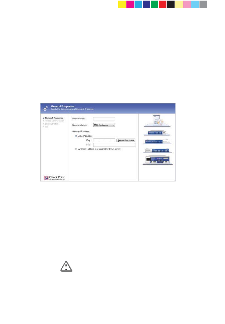
3. Select Wizard Mode. The wizard opens to General Properties.
4. Type a name for the Check Point 1100 Appliance object and make sure
that the gateway platform is set to 1100 Appliances.
5. Select one of the following options for getting the gateway's IP address:
x Static IP address - enter the IPv4 address of the appliance. Note
that if the Check Point 1100 Appliance has not yet been set up and
defined, the Resolve from Name option does not work at this point.
x Dynamic IP address (e.g. assigned by DHCP server)
Click Next.
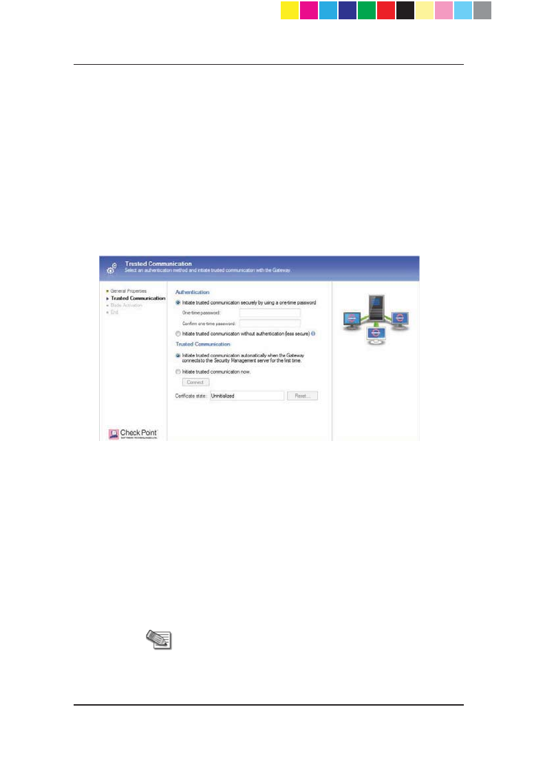
6. If you specified a static IP address, the Authentication and Trusted
Communication sections show (if you specified a dynamic IP address, go
to step 7).
a) In the Authentication section, select one of the options:
Initiate trusted communication securely by using a one-time
password - the one-time password is used to authenticate
communication between the Security Gateway and the Security
Management server in a secure manner.
Enter a one-time password and confirm it. This password is
only used for establishing the initial trust. Once established, trust
is based on security certificates.
Important - This password must be identical to the
one-time password you define for the appliance in the
First Time Configuration Wizard
CP_1100Appliance_GettingStartedG18 18CP_1100Appliance_GettingStartedG18 18 25/02/2013 10:05:3025/02/2013 10:05:30
Page 19
Initiate trusted communication without authentication (less
secure) - select this option only if you are sure that there is no
risk of imposture (for example, when in a lab setting).
b) In the Trusted Communication section, select one of the initialization
options:
Initiate trusted communication automatically when the
Gateway connects to the Security Management server for
the first time - trust will be established when the Gateway will
connect for the first time.
Initiate trusted communication now and click Connect. A
status window appears. Use this option only if you have already
set up the appliance.
The Certificate state field displays the current certificate status.
Click Next and go to step 8.
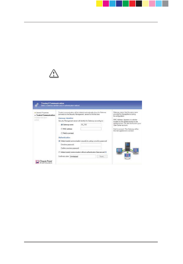
7. If you specified a dynamic IP address, the Gateway Identifier and
Authentication sections show.
a) Select one of the identifiers:
Gateway name ± enter the same name that you will give the
appliance during its initial configuration.
MAC address ± enter the MAC address that is on the sticker on
the appliance or on the box.
First to connect ± means that this Gateway will be the next
appliance to connect.
Note - For your convenience, if the gateway name
matches, the Security Management Server will identify
the gateway regardless of its MAC address.
CP_1100Appliance_GettingStartedG19 19CP_1100Appliance_GettingStartedG19 19 25/02/2013 10:05:3025/02/2013 10:05:30
Page 20
b) In the Authentication section, select one of the options:
Initiate trusted communication securely by using a one-time
password - the one-time password is used to authenticate
communication between the Security Gateway and the Security
Management server in a secure manner.
Enter a one-time password and confirm it. This password is
only used for establishing the initial trust. Once established, trust
is based on security certificates.
Important - This password must be identical to the
one-time password you define for the appliance in the
First Time Configuration Wizard
Initiate trusted communication without authentication (less
secure) - select this option only if you are sure there is no risk of
malicious behavior (for example, when in a lab setting).
Click Next.
8. In the Blade Activation page, select the security and software blades that
you want to activate and configure.
To configure blades now:
a) Make sure that the Activate and configure software blades now
option is selected.
b) Select the check boxes next to the blades you want to activate and
configure.
To configure blades later:
CP_1100Appliance_GettingStartedG20 20CP_1100Appliance_GettingStartedG20 20 25/02/2013 10:05:3025/02/2013 10:05:30
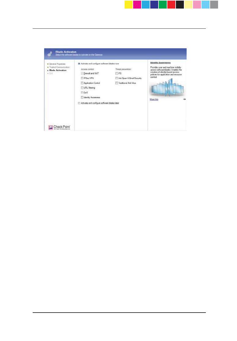
Page 21
x Select the Activate and configure software blades later option.
Do this later by editing the object from the Network Objects tree.
Click Next.
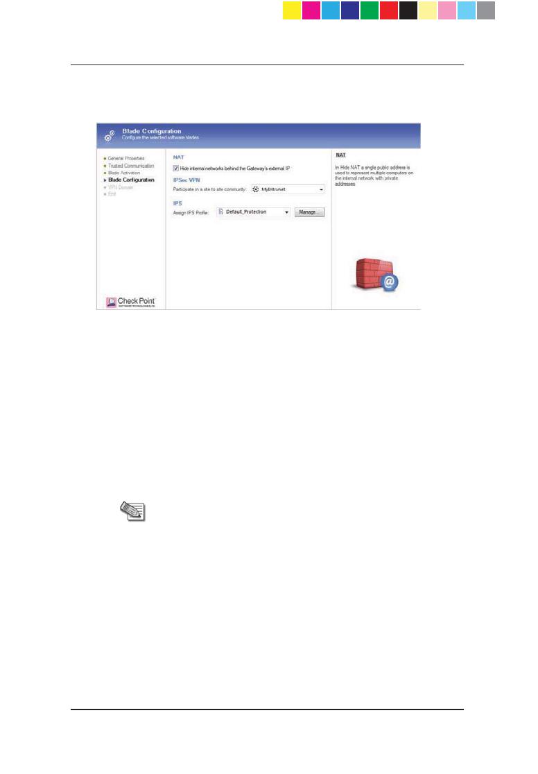
9. If you selected to activate and configure software blades now, configure
the required options:
x For NAT, the +LGHLQWHUQDOQHWZRUNVEHKLQGWKH*DWHZD\¶V
external IP checkbox is selected by default. Clear it, if you do not
want to use this feature.
x For IPSec VPN: Make sure that the VPN community has been
predefined. If it is a star community, Check Point 1100 Appliance is
added as a satellite gateway.
Select a VPN community that the Gateway participates in from
the Participate in a site to site community list.
x For IPS:
Select a profile from the Assign IPS Profile list or click Manage
to create/edit an IPS profile.
x For Identity Awareness:
Complete the wizard that opens to define the Identity Awareness
acquisition sources.
To configure acquisition sources at a later time, click Cancel in
the wizard. After you define the Check Point 1100 Appliance
object, you can configure Identity Awareness acquisition sources
by editing the Check Point 1100 Appliance object.
CP_1100Appliance_GettingStartedG21 21CP_1100Appliance_GettingStartedG21 21 25/02/2013 10:05:3025/02/2013 10:05:30
Page 22
x For Application Control, URL Filtering, Anti-Spam and Email
Security, and Traditional Anti-Virus, there are no other settings to
configure.
Click Next.
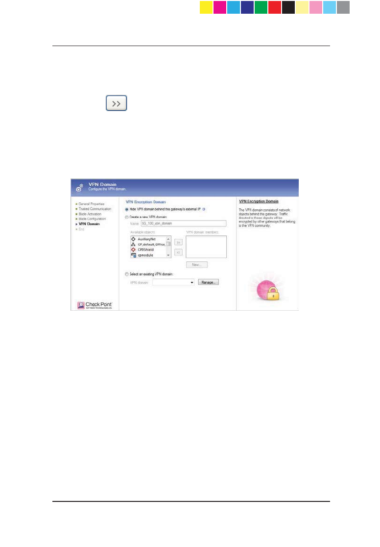
10. If you selected IPSEC VPN, configure VPN Encryption Domain settings.
x To hide the VPN domain, select Hide VPN domain behind this
gateway's external IP.
The VPN domain contains network objects behind this gateway.
Instead of defining the network topology behind this gateway, it is
possible to use this option, which sets the VPN domain to be this
JDWHZD\¶VH[WHUQDO,3DGGUHVV7KLVRSWLRQLVRQO\DSSOLFDEOHLI\RX
FKRVHWRKLGHDOOLQWHUQDOQHWZRUNVEHKLQGWKLVJDWHZD\¶VH[WHUQDO,3
VHHJDWHZD\¶V1$7VHWWLQJV$OORXWJRLQJWUDIILFIURPQHWZRUNV
behind this gateway to other sites that participate in VPN community
will be encrypted (including replies, of course).
Note - If you choose this option, connections that are
initiated from other sites that are directed to hosts behind
this gateway will not be encrypted. If you require access
to hosts behind this gateway, either choose other options
(define VPN topology) or, if possible, make sure all traffic
IURPRWKHUVLWHVLVGLUHFWHGWRWKLVJDWHZD\¶VH[WHUQDO,3
and define corresponding NAT port-forwarding rules, such
as: Translate the destination of incoming HTTP
FRQQHFWLRQVWKDWDUHGLUHFWHGWRWKLVJDWHZD\¶VH[WHUQDO,3
to the IP address of a web server behind this gateway.
x To create a new VPN domain group, go to step 11.
x To select a predefined VPN domain, go to step 12.
11. To create a new VPN domain group:
CP_1100Appliance_GettingStartedG22 22CP_1100Appliance_GettingStartedG22 22 25/02/2013 10:05:3025/02/2013 10:05:30
Page 23
a) Make sure that the Create a new VPN domain option is selected.
b) In the Name field, enter a name for the group.
c) From the Available objects list, select the applicable object(s) and
click . The objects are added to the VPN domain members list.
d) If necessary, create a new object by pressing New.
12. To select a predefined VPN domain:
a) Choose the Select an existing VPN domain option.
b) From the VPN Domain list, select the domain.
Click Next.
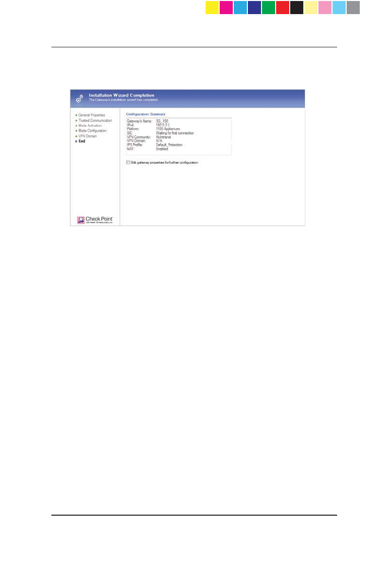
13. In the Installation Wizard Completion page, you see a summary of the
configuration parameters you set and can do further actions.
CP_1100Appliance_GettingStartedG23 23CP_1100Appliance_GettingStartedG23 23 25/02/2013 10:05:3025/02/2013 10:05:30
Page 24
x Select Edit Gateway properties for further configuration to
configure the Security Gateway. When you click Finish, the General
Properties window of the newly defined object opens.
Click Finish.
Preparing to Install the Security Policy
Use this procedure to prepare the policy for automatic installation when the
gateway connects.
1. Click Policy > Install from the menu.
2. In the Install Policy window, choose:
x The installation targets - the Check Point 1100 Appliance Security
Gateways on which the policy should be installed
x The policy components (Network Security, QoS, etc.).
By default, all gateways that are managed by the Security Management
server are available for selection.
3. In the Installation Mode section, select how the security policy is installed:
x On each selected gateway independently
x On all selected gateways, if it fails do not install on gateways of the
same version
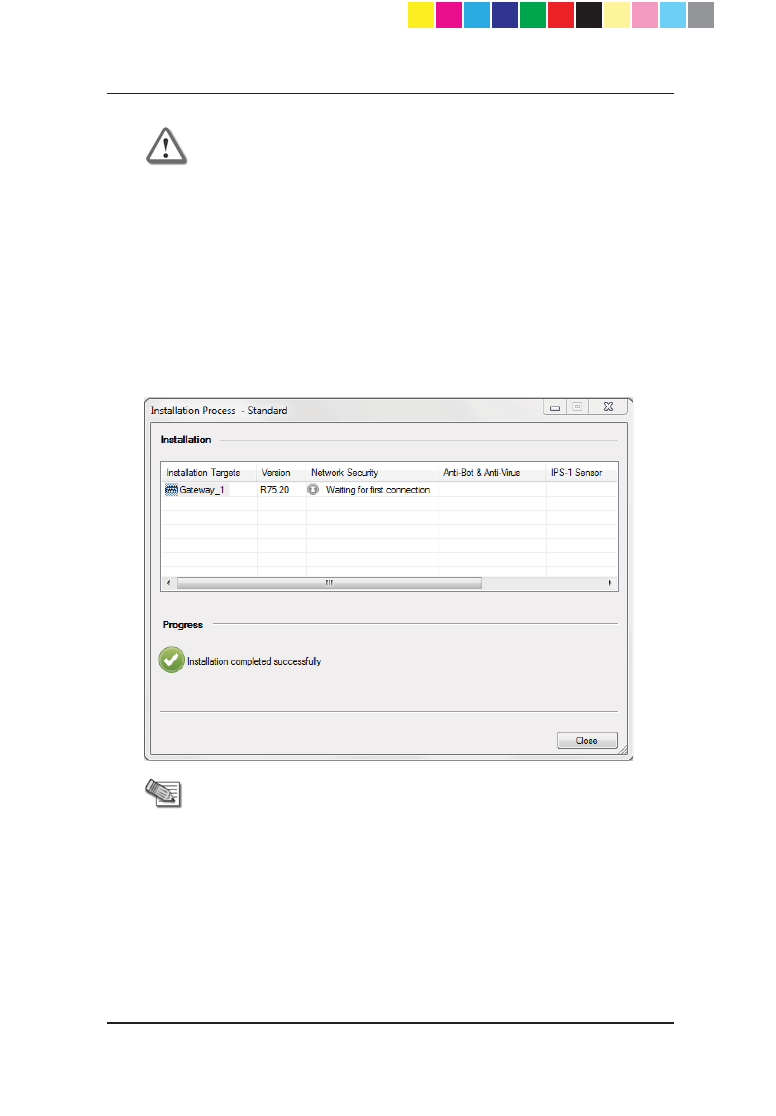
4. Click OK. The Installation Process window shows the status of the
Network Security policy for the selected target.
CP_1100Appliance_GettingStartedG24 24CP_1100Appliance_GettingStartedG24 24 25/02/2013 10:05:3025/02/2013 10:05:30
Page 25
Important - If you used the Management First
configuration option:
x The Check Point 1100 Appliance object is defined
but the appliance is not set up
x The Installation Process window shows the
"Waiting for first connection" status and the
message "Installation completed successfully".
This means that the policy is successfully
prepared for installation. When the appliance will
be set up and the gateway connects to the
Security Management Server, it establishes trust
and then attempts to install the policy
automatically.
Note - If you used the Gateway First configuration
option:
x Upon successful completion of this step, the policy
is pushed to the Check Point 1100 Appliance.
x For a list of possible statuses, see Viewing the
Policy Installation Status (on page 61).
Continue tracking the status of the security policy installation with the Policy
Installation Status window and the status bar ("Viewing the Policy Installation
Status " on page 61).
CP_1100Appliance_GettingStartedG25 25CP_1100Appliance_GettingStartedG25 25 25/02/2013 10:05:3025/02/2013 10:05:30

Page 26
Setting Up the Check Point 1100
Appliance
1. Remove the Check Point 1100 Appliance from the shipping carton and
place it on a tabletop.
2. Identity the network interface marked as LAN1. This interface is
preconfigured with the IP address 192.168.1.1.
Connecting the Cables
To connect the cables on Check Point 1100 Appliance models:
1. Connect the power supply unit to the appliance and to a power outlet. The
appliance is turned on once the power supply unit is connected to an
outlet. The Power LED on the front panel turns on. This indicates that the
appliance is turned on. The Notice LED on the front panel starts blinking.
This indicates that the appliance is booting up. When the Notice LED turns
off, the appliance is ready for login.
2. Connect the standard network cable to the network interface port (LAN1)
on the appliance and to the network adapter on your PC.
3. Connect another standard network cable to the WAN interface on the
appliance and to the external modem, external router, or network point (in
ADSL models, connect a telephone cable to the ADSL port).
CP_1100Appliance_GettingStartedG26 26CP_1100Appliance_GettingStartedG26 26 25/02/2013 10:05:3025/02/2013 10:05:30

Page 27
Using the First Time Configuration Wizard
Configure Check Point 1100 Appliance with the First Time Configuration
Wizard.
During the wizard, click Quit to save the settings that have been configured
and close the wizard.
Note - In the First Time Configuration Wizard, you may not see all
the pages described in this guide. The pages that show in the
wizard depend on your Check Point 1100 Appliance model and the
options you select.
Starting the First Time Configuration Wizard
To configure the Check Point 1100 Appliance for the first time after you
complete the hardware setup, you use the First Time Configuration Wizard.
If you do not complete the wizard, the wizard will run again the next time you
connect to the appliance. This can occur if one of these conditions applies:
x You have not completed the wizard.
x The browser window is closed.
x The appliance is restarted while you run the wizard.
x There is no activity for a predefined amount of time (the default is 10
minutes).
Note - After you complete the wizard, you can use the WebUI
(Web User Interface) to change settings configured with the First
Time Configuration Wizard and to configure advanced settings.
To open the WebUI, enter one of these addresses in the browser:
x http://my.firewall
x http://192.168.1.1
If a security warning message is shown, confirm it and continue.
For more details, see Appendix A: Browser Security Warnings (on
page 59).
CP_1100Appliance_GettingStartedG27 27CP_1100Appliance_GettingStartedG27 27 25/02/2013 10:05:3025/02/2013 10:05:30
Page 28
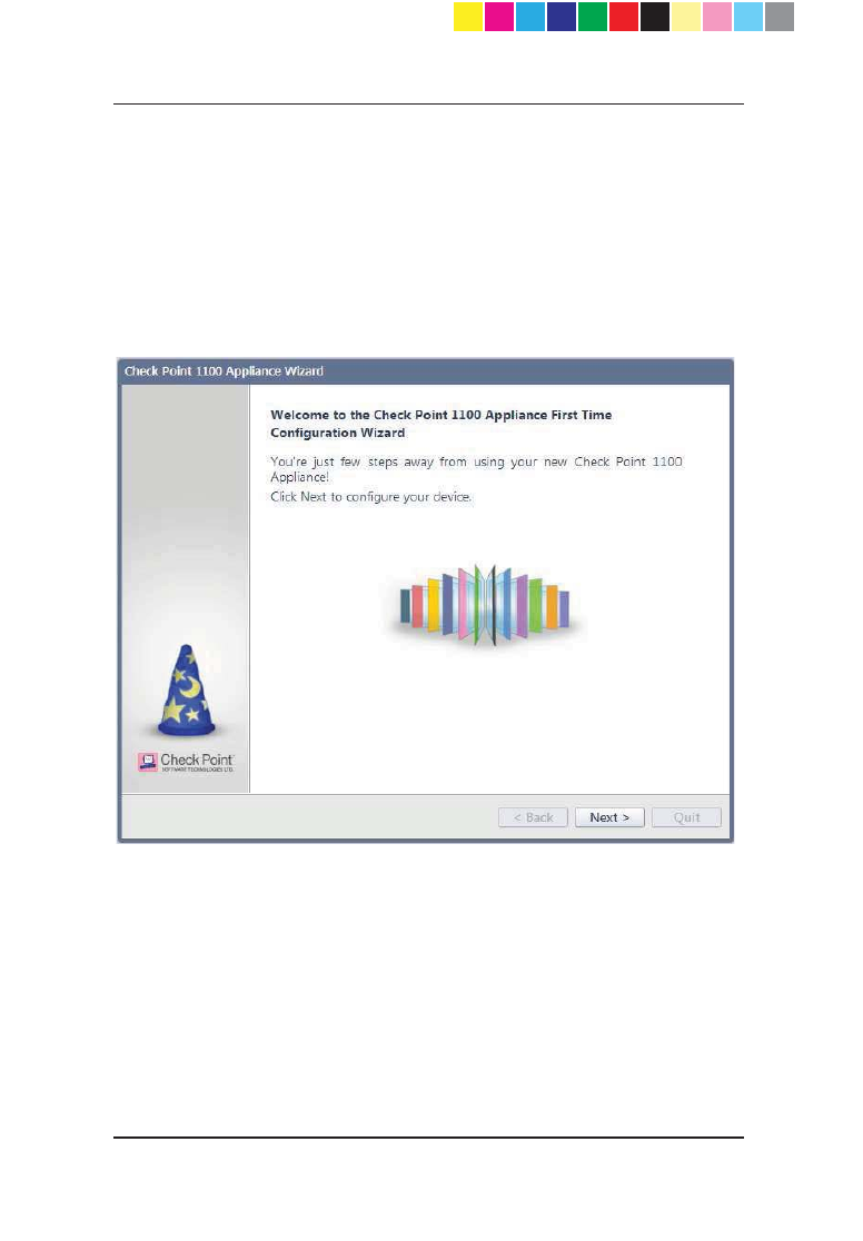
To start the First Time Configuration Wizard:
Initiate a connection from a browser to http://my.firewall and confirm
the security message.
The First Time Configuration Wizard runs.
Welcome
The Welcome page introduces the product.
CP_1100Appliance_GettingStartedG28 28CP_1100Appliance_GettingStartedG28 28 25/02/2013 10:05:3025/02/2013 10:05:30
Page 29
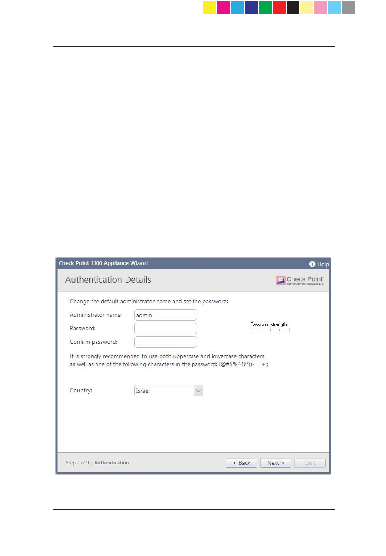
Authentication Details
In the Authentication Details page, enter these details necessary for logging
in to the Check Point 1100 Appliance WebUI application or if the wizard
terminates abnormally:
x Administrator Name - We recommend that you change the default
"admin" login name of the administrator. The name is case sensitive.
x Password - You can use the Password strength meter to measure the
strength of your password. This meter is only used as an indicator and
does not enforce creation of a password with a specified number of
characters or character combination.
The minimum length for a strong password is 6 characters that contain at
least one capital letter, one lower case letter and a special character. If
you specify such a password, a green bar in the last section of the meter
will appear. It is strongly recommended to create a password using both
uppercase and lowercase letters.
x Confirm Password - Retype the password.
x Country - Select a country from the list (for wireless network models).
CP_1100Appliance_GettingStartedG29 29CP_1100Appliance_GettingStartedG29 29 25/02/2013 10:05:3025/02/2013 10:05:30
Page 30
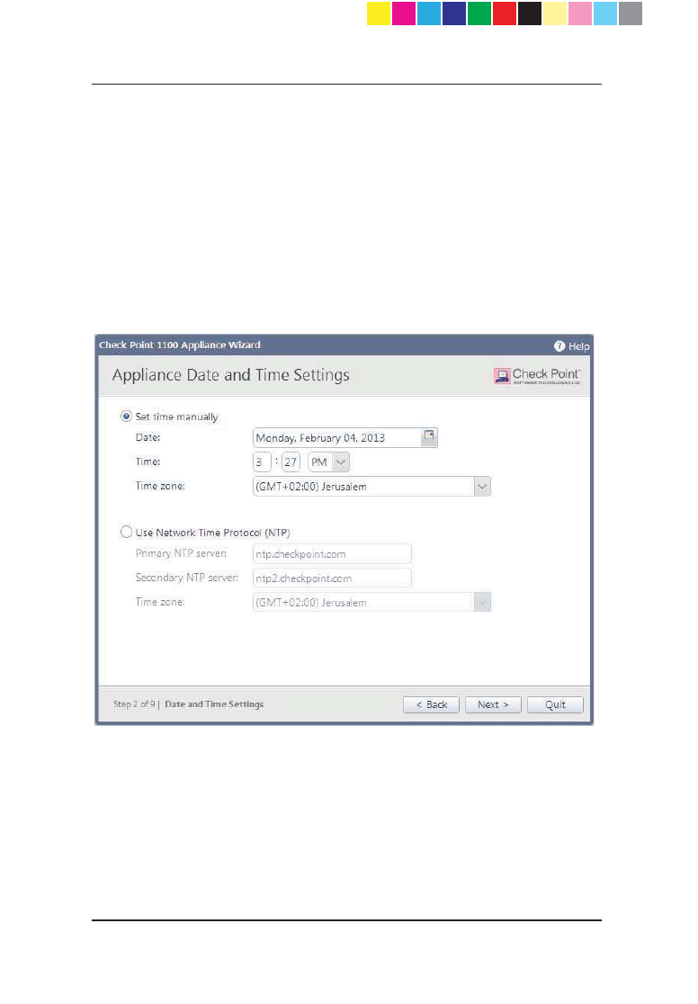
Appliance Date and Time Settings
In the Appliance Date and Time Settings page, configure the appliance's
date, time and time zone settings manually or use the Network Time Protocol
option.
When you set the time manually, the host computer's settings are used for the
default date and time values. If necessary, change the time zone setting to
reflect your correct location. Note that although not specified, Daylight Savings
Time is automatically enabled by default. You can change this in the WebUI
application on the Device > Date and Time page.
When you use the NTP option, there are two default servers you can use.
These are ntp.checkpoint.com and ntp2.checkpoint.com.
CP_1100Appliance_GettingStartedG30 30CP_1100Appliance_GettingStartedG30 30 25/02/2013 10:05:3025/02/2013 10:05:30
Page 31
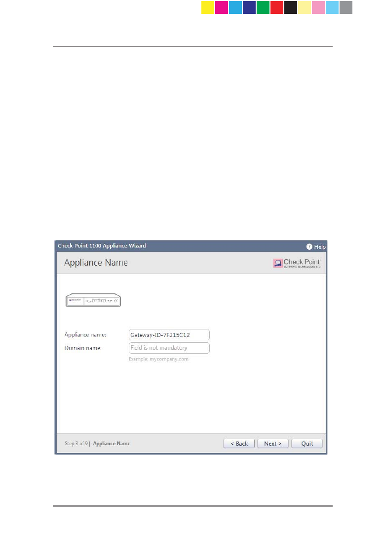
Appliance Name
In the Appliance Name page, enter a name for the appliance that is used to
identify the Check Point 1100 Appliance and a domain name.
x Appliance name - Enter a name for the appliance.
x Domain name - When the gateway performs DNS resolving for a certain
REMHFW¶VQDPHWKHGRPain name is appended to the object name. This
enables hosts in the network to lookup hosts by using only their internal
names. This field is not mandatory.
The name of the appliance must be identical to the name of the gateway object
in the Security Management Server in one of these cases:
x When Check Point 1100 Appliance does not use a static IP and the
unique identifier for the gateway in SmartDashboard is set to use the
Gateway name.
x When Check Point 1100 Appliance is managed through
SmartProvisioning.
CP_1100Appliance_GettingStartedG31 31CP_1100Appliance_GettingStartedG31 31 25/02/2013 10:05:3025/02/2013 10:05:30
Page 32
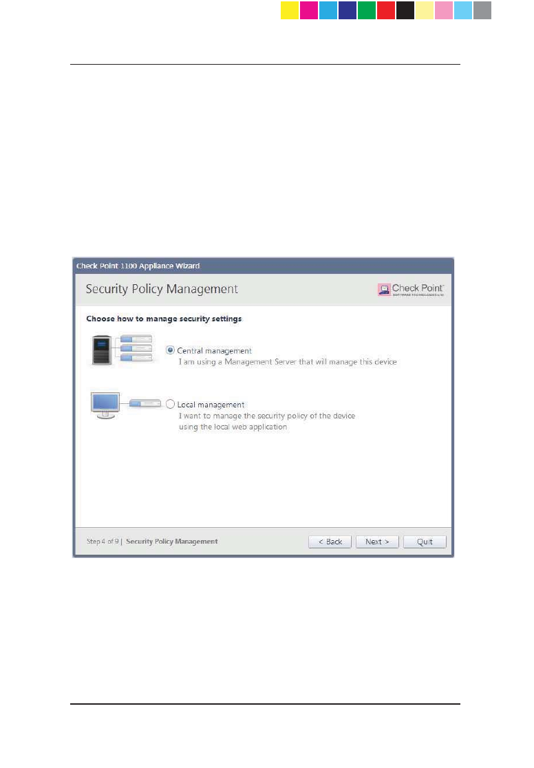
Security Policy Management
In the Security Policy Management page, select how to manage security
settings.
x Central management - The Check Point 1100 Appliance is only a
Security Gateway. It is managed by a remote Security Management
Server that defines the gateway object and the security policy. The WebUI
is used only for configuring the appliance.
x Local management - The Check Point 1100 Appliance is a Security
Gateway and uses the appliance's WebUI for local management. The
WebUI manages the security policy that Check Point 1100 Appliance
enforces and activated software blades.
CP_1100Appliance_GettingStartedG32 32CP_1100Appliance_GettingStartedG32 32 25/02/2013 10:05:3025/02/2013 10:05:30

Page 33
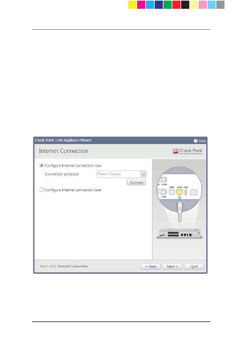
Internet Connection
In the Internet Connection page, configure your Internet connectivity details
or select the Configure Internet connection later option and then configure
connectivity through the WebUI application at a later time.
To configure Internet connection now:
1. Select Configure Internet connection now.
2. From the Connection Protocol drop down list, select the protocol used
for connecting to the Internet.
3. Fill in the fields for the selected connection protocol. The information you
must enter is different for each protocol. You can get it from your Internet
Service Provider (ISP).
x Static IP - A fixed (non-dynamic) IP address.
x DHCP - Dynamic Host Configuration Protocol (DHCP) automatically
issues IP addresses within a specified range to devices on a network.
This is a common option when you connect through a cable modem.
x PPPoE (PPP over Ethernet) - A network protocol for encapsulating
Point-to-Point Protocol (PPP) frames inside Ethernet frames. It is
used mainly with DSL services where individual users connect to the
DSL modem over Ethernet and in plain Metro Ethernet networks.
x PPTP - The Point-to-Point Tunneling Protocol (PPTP) is a method for
implementing virtual private networks. PPTP uses a control channel
over TCP and a GRE tunnel operating to encapsulate PPP packets.
x L2TP - Layer 2 Tunneling Protocol (L2TP) is a tunneling protocol
used to support virtual private networks (VPNs). It does not provide
any encryption or confidentiality by itself. It relies on an encryption
protocol that it passes within the tunnel to provide privacy.
x Cellular Modem - Connect to the Internet using a wireless modem to
a cellular ISP.
x Analog Modem - Connect to the Internet using an analog modem.
x ADSL - Connect to the Internet using ADSL.
x Bridge - Connects multiple network segments at the data link layer
(Layer 2).
4. In the DNS Server field (shown for Static IP and Bridge connections),
enter the DNS server address information in the relevant fields. For
DHCP, PPPoE, PPTP, L2TP, ADSL, Analog Modem, and Cellular
Modem, the DNS settings are supplied by your service provider. You can
override these settings later in the WebUI application under the Device >
DNS page.
It is recommended to configure the DNS since Check Point 1100
Appliance needs to perform DNS resolving for different functions. For
example, for connecting to Check Point User Center during license
CP_1100Appliance_GettingStartedG33 33CP_1100Appliance_GettingStartedG33 33 25/02/2013 10:05:3025/02/2013 10:05:30
Page 34
activation or when Application Control, Web Filtering, Anti-Virus or Anti-
Spam services are enabled.
5. Select Monitor connection status to let the appliance probe for Internet
connectivity. It is possible to get an IP address from your ISP without the
capability to connect to the Internet. This option verifies that you have
connectivity. You can change this setting later in the WebUI.
6. Click Connect to connect to your ISP now and test you connection's
status. If you selected Monitor connection status, the gateway starts
probing the Internet once the connection is up. The probing status is
available in the WebUI.
Indication regarding success or failure of the connection appears at the bottom
of the page.
To configure the Internet connection at a later time:
Select Configure Internet connection later.
CP_1100Appliance_GettingStartedG34 34CP_1100Appliance_GettingStartedG34 34 25/02/2013 10:05:3025/02/2013 10:05:30
Page 35
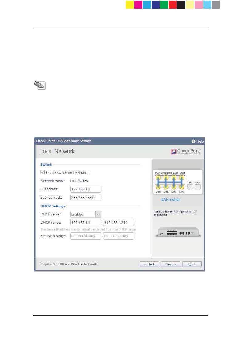
Local Network
In the Local Network page, select whether to enable or disable switch on LAN
ports and configure your network settings. By default, they are enabled. You
can change the IP address and stay connected as the appliance's original IP is
kept as an alias IP until the first time you boot the appliance.
Note - DHCP is enabled by default and a default range is
configured. Make sure to set the range accordingly and be
careful not to include predefined static IPs in your network. Set
the exclusion range for IP addresses that should not be defined
by the DHCP server.
The appliance's IP address is automatically excluded from the
range. For example , if the appliance IP is 1.1.1.1 the range also
starts from 1.1.1.1, but will exclude its own IP address.
CP_1100Appliance_GettingStartedG35 35CP_1100Appliance_GettingStartedG35 35 25/02/2013 10:05:3025/02/2013 10:05:30

Page 36
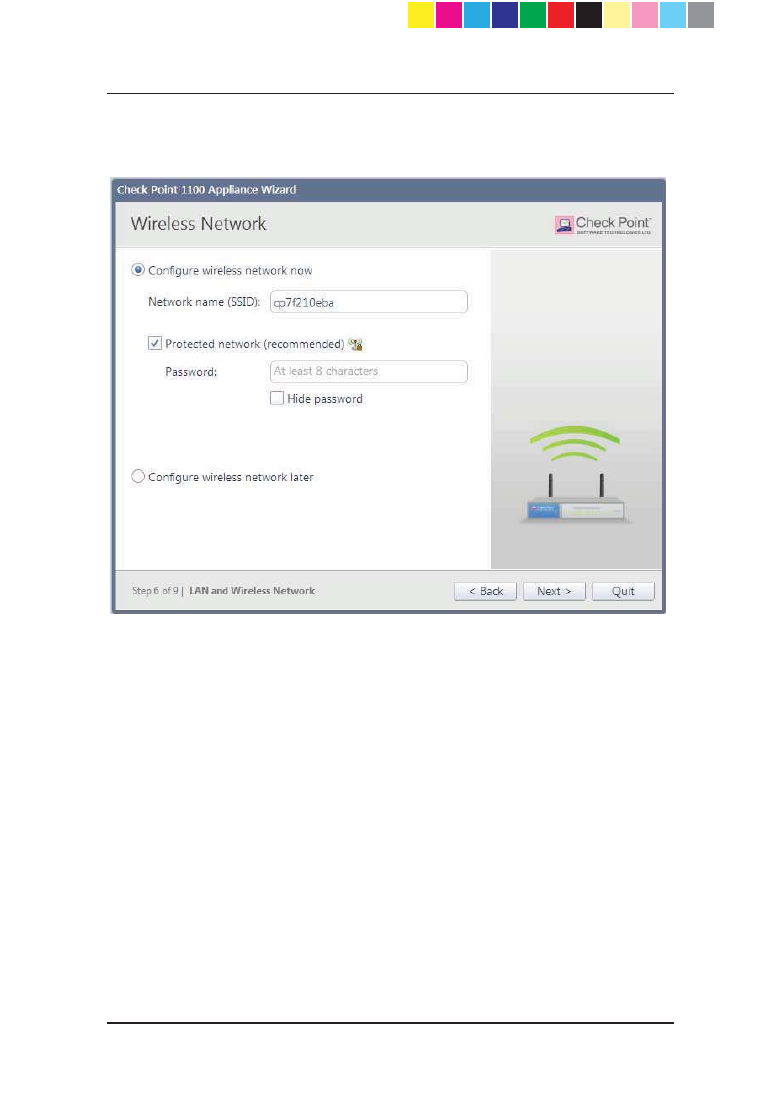
Wireless Network (for Wireless Network Models)
In the Wireless Network page, configure wireless connectivity details.
When you configure a wireless network, you must define a network name
(SSID). The SSID (service set identifier) is a unique string that identifies a
WLAN network to clients that try to open a wireless connection with it.
It is recommended to protect the wireless network with a password. Otherwise,
a wireless client can connect to the network without authentication.
To configure the wireless network now:
1. Select Configure wireless network now.
2. Enter a name in the Network name (SSID) field. This is the wireless
network name shown to clients that look for access points in the
transmission area.
3. Select Protected network (recommended) if the wireless network is
protected by password.
4. Enter a Password.
5. Click Hide to conceal the password.
CP_1100Appliance_GettingStartedG36 36CP_1100Appliance_GettingStartedG36 36 25/02/2013 10:05:3025/02/2013 10:05:30
Page 37
To configure the wireless network at a different time:
Select Configure wireless network later.
CP_1100Appliance_GettingStartedG37 37CP_1100Appliance_GettingStartedG37 37 25/02/2013 10:05:3025/02/2013 10:05:30

Page 38
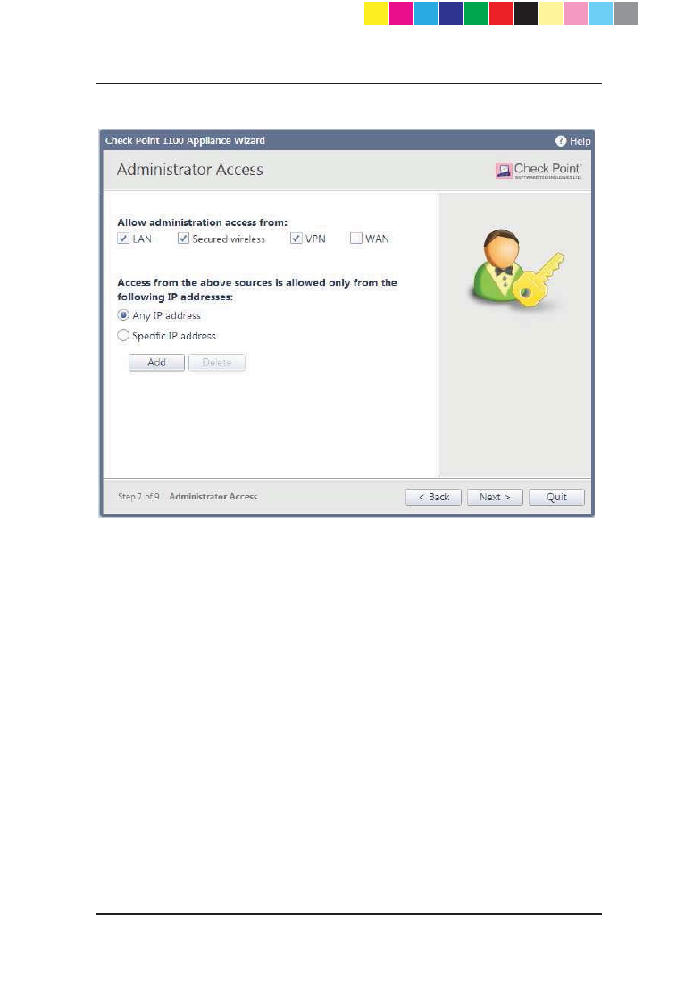
Administrator Access
In the Administrator Access page, configure if administrators can use Check
Point 1100 Appliance from a specified IP address or any IP address.
To configure administrator access:
1. Select from where administrators are allowed access:
x LAN - All internal physical ports
x Secured wireless - Wireless networks with a secure password
x VPN - Using encrypted traffic through VPN tunnels from a remote site
or using a remote access client
x WAN - Clear traffic from the Internet (not recommended)
2. Select the IP address that the administrator can access Check Point 1100
Appliance from:
x Any IP address
x Specific IP address - Click Add to configure the IP address
information.
a) In the IP Address Configuration window, select an option:
Specific IP address - Enter the IP address or click Get IP from
my computer.
Specific network - Enter the network address and subnet mask.
CP_1100Appliance_GettingStartedG38 38CP_1100Appliance_GettingStartedG38 38 25/02/2013 10:05:3025/02/2013 10:05:30
Page 39
b) Click Apply.
CP_1100Appliance_GettingStartedG39 39CP_1100Appliance_GettingStartedG39 39 25/02/2013 10:05:3025/02/2013 10:05:30

Page 40
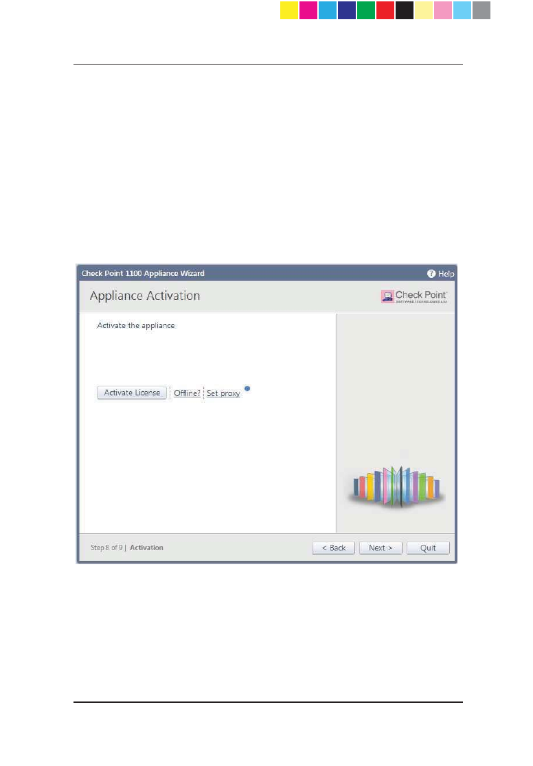
Appliance Activation
In the Appliance Activation page, the appliance can connect to the Check
Point User Center with its credentials to pull the license information and
activate the appliance.
If you have Internet connectivity configured:
x Click Activate License.
You will be notified that you successfully activated the appliance and you
will be shown the status of your license for each blade.
If you are working offline while configuring the appliance:
1. From a computer with authorized access to the Check Point User Center
(http://supportcenter.checkpoint.com) do procedure a or b:
a) Use your User Center account:
Log into your User Center account.
Select the specified container of your Check Point 1100
Appliance.
From the Product Information tab, click License > Activate.
This message is shown: "Licenses were generated
successfully."
Click Get Activation File and save the file locally.
b) Register your appliance:
Go to http://register.checkpoint.com
Fill in your appliance details and click Activate.
This message is shown: "Licenses were generated
successfully."
Click Get Activation File and save the file locally.
2. In the Appliance Activation page of the First Time Configuration Wizard,
click Offline.
The Import from File window opens.
3. Browse to the activation file you downloaded and click Import. The
activation process starts.
You will be notified that you successfully activated the appliance and you
will be shown the status of your license for each blade.
If there is a proxy between your appliance and the Internet, you
must configure the proxy details before you can activate your
license:
1. Click Set proxy.
CP_1100Appliance_GettingStartedG40 40CP_1100Appliance_GettingStartedG40 40 25/02/2013 10:05:3025/02/2013 10:05:30
Page 41
2. Select Use proxy server and enter the proxy server Address and Port.
3. Click Apply.
4. Click Activate License.
You will be notified that you successfully activated the appliance and you
will be shown the status of your license for each blade.
To postpone appliance registration and get a 30-day trial license:
1. Click Next.
The License activation was not complete notification message is shown.
2. Click OK.
The appliance uses a 30-day trial license for all blades. You can register
the appliance later from the WebUI Device > License page.
CP_1100Appliance_GettingStartedG41 41CP_1100Appliance_GettingStartedG41 41 25/02/2013 10:05:3025/02/2013 10:05:30
Page 42
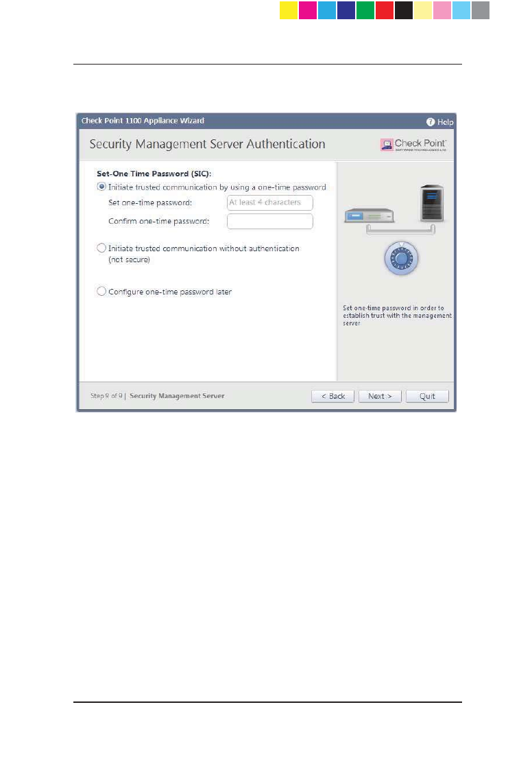
Centrally Managed - Security Management Server
Authentication
When you select central management as your security policy management
method, the Security Management Server Authentication page opens.
Use this page to select an option to authenticate trusted communication with
the Security Management Server:
x Initiate trusted communication securely by using a one-time
password - The one-time password is used to authenticate
communication between Check Point 1100 Appliance and the Security
Management Server securely.
Enter a one-time password and confirm it. This password is only used for
establishing the initial trust. When established, trust is based on security
certificates.
Important - This password must be identical to the Secure
Communication authentication one-time password configured
for the Check Point 1100 Appliance object in the
SmartDashboard of the Security Management server (see
step 6 ("Defining the Object in SmartDashboard " on page
17)).
x Initiate trusted communication without authentication (not secure) -
Use this option only if there is no risk of malicious behavior (for example,
when in a lab setting).
CP_1100Appliance_GettingStartedG42 42CP_1100Appliance_GettingStartedG42 42 25/02/2013 10:05:3025/02/2013 10:05:30
Page 43
x Configure one-time password later - Set the one-time password at a
different time using the WebUI application.
CP_1100Appliance_GettingStartedG43 43CP_1100Appliance_GettingStartedG43 43 25/02/2013 10:05:3025/02/2013 10:05:30
Page 44
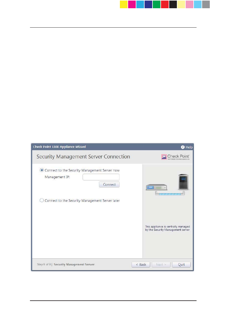
Centrally Managed - Security Management Server
Connection
After setting a one-time password for the Security Management Server and the
Check Point 1100 Appliance, you can connect to the Security Management
Server to establish trust with between the Security Management Server and
Check Point 1100 Appliance.
Use this page to setup the connection:
x Connect to the Security Management Server now - Select this option to
connect to the Security Management Server now.
x Management IP - Enter the IP address of the Security Management
Server.
x Connect - Upon successful connection to the Security Management
Server, the security policy will automatically be fetched and installed.
x Connect to the Security Management Server later - Select this option
to connect to the Security Management Server later.
CP_1100Appliance_GettingStartedG44 44CP_1100Appliance_GettingStartedG44 44 25/02/2013 10:05:3025/02/2013 10:05:30
Page 45
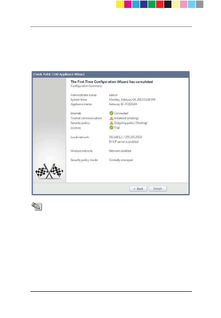
Summary
The Summary page shows the details of the elements configured with the First
Time Configuration Wizard.
Click Finish to complete the First Time Configuration Wizard. The WebUI
opens on the Home > System page.
Note - You should back up the system configuration in the WebUI.
Go to the Device > Backup page.
CP_1100Appliance_GettingStartedG45 45CP_1100Appliance_GettingStartedG45 45 25/02/2013 10:05:3025/02/2013 10:05:30

Page 46
Large-scale Deployment
Predefining a Centrally Managed
Deployment
To manage the Check Point 1100 Appliance in a centrally managed
deployment, you must install a Security Management Server and
SmartConsole clients that operate with Check Point 1100 Appliance.
The Security Management Server versions that operate with Check Point 1100
Appliance are versions R75.46, R76 and higher.
)RULQVWDOODWLRQLQVWUXFWLRQVVHHWKHYHUVLRQ¶Vrelease notes
(http://supportcenter.checkpoint.com).
After installing the SmartConsole clients you can define the Check Point 1100
Appliance object in SmartDashboard and prepare the security policy (in small-
scale deployments) or create a SmartLSM profile (in large-scale deployments).
Defining a SmartLSM Profile
SmartLSM lets you manage a large number of Check Point 1100 Appliance
gateways from one Security Management Server. When you use a SmartLSM
profile, you reduce the administrative overhead per gateway by defining most
of the gateway properties, as well as the policy, per profile.
Use SmartDashboard to define a single SmartLSM profile for Check Point 1100
Appliance.
To define a single SmartLSM profile Check Point 1100 Appliance:
1. Log in to SmartDashboard using your Security Management credentials.
2. Open the Security Policy that you want to be enforced on the Check Point
1100 Appliance SmartLSM Security Gateways.
3. From the Network Objects tree, right-click Check Point and select
SmartLSM Profile > 80 Series Gateway.
The SmartLSM Security Profile window opens.
4. Define the SmartLSM security profile using the navigation tree in this
window.
To open the online help for each window, click Help.
5. Click OK and then install the policy.
Note - To activate SmartProvisioning functionality, a
security policy must be installed on the LSM profile.
CP_1100Appliance_GettingStartedG46 46CP_1100Appliance_GettingStartedG46 46 25/02/2013 10:05:3025/02/2013 10:05:30

Page 47
Deploying with SmartProvisioning
You can use SmartProvisioning to manage many Check Point 1100 Appliance
gateway objects with deployed SmartLSM security profiles. Configure these
appliances using the First Time Configuration Wizard (on page 27) or a USB
drive configuration file . For more information about the USB drive configuration
file, see the Check Point 1100 Appliance Administration Guide.
For more information about large-scale deployment using SmartProvisioning,
see the SmartProvisioning Administration Guide.
CP_1100Appliance_GettingStartedG47 47CP_1100Appliance_GettingStartedG47 47 25/02/2013 10:05:3025/02/2013 10:05:30

CP_1100Appliance_GettingStartedG48 48CP_1100Appliance_GettingStartedG48 48 25/02/2013 10:05:3025/02/2013 10:05:30

Page 49
Chapter 3
Check Point 1100
Appliance Hardware
In This Chapter
Front Panel
Back Panel
There are four Check Point 1100 Appliance models:
x Wired
x Wireless Network
x ADSL
x Wireless Network + ADSL
The differences in the front and back panels are described in this section.
CP_1100Appliance_GettingStartedG49 49CP_1100Appliance_GettingStartedG49 49 25/02/2013 10:05:3025/02/2013 10:05:30
Page 50
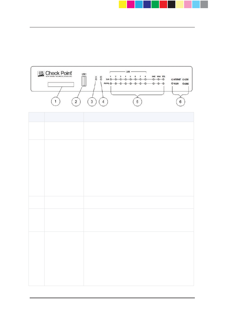
Front Panel
Wireless Network + ADSL Model
Key Item Description
1 Express Card Express card slot that is used for cellular modems
in Express Card form factor.
2 USB1 port
USB1 port that is used for:
x Cellular and analog modems.
x External storage devices (for example to
save traffic logs).
x Reinstalling the appliance with new
firmware.
x Running a first-time configuration script.
3 Power LED Green when the appliance is turned on.
4 Notice LED
x Blinking green during boot.
x Red when the appliance has a resource
problem such as memory shortage.
5
LAN1 - LAN8,
DMZ, WAN
LEDs
Link Indicator
x Orange when the port speed is 1000 Mbps.
x Green when the port speed is 100 Mbps.
x Not lit when the port speed is 10 Mbps.
Activity Indicator
x Blinking green when encountering traffic.
CP_1100Appliance_GettingStartedG50 50CP_1100Appliance_GettingStartedG50 50 25/02/2013 10:05:3025/02/2013 10:05:30

Page 51
Key Item Description
DSL LED
Link Indicator
x Green when DSL connection is
established.
x Blinking green when establishing a DSL
connection.
x Not lit when DSL connection is not
established.
Activity Indicator
x Blinking green when encountering traffic.
x Not lit when the DSL line is idle.
(Only in ADSL and Wireless Network + ADSL
models)
6
Internet LED
x Green when connected to the Internet.
x Blinking red when the Internet connection
is configured but fails to connect.
WLAN LED
Blinking green when encountering traffic.
(Only in Wireless Network and Wireless Network +
ADSL models)
USB1, USB2
LEDs
Orange when a USB device is connected.
CP_1100Appliance_GettingStartedG51 51CP_1100Appliance_GettingStartedG51 51 25/02/2013 10:05:3025/02/2013 10:05:30
Page 52
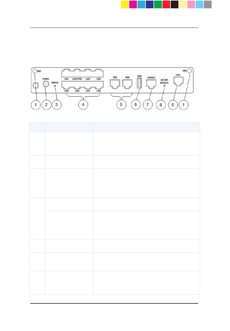
Back Panel
Wireless Network + ADSL Model
Key Item Description
1 ANT1 and ANT2
Ports for attaching wireless network antennas.
(Only in Wireless Network and Wireless Network
+ ADSL models)
2 Power outlet Connects to the power supply unit's cable.
3 Reboot button
Lets you forcibly reboot the appliance. The
button is recessed into the appliance chassis to
prevent accidental reboot. The appliance reboots
immediately after you press the button.
4
LAN1 - LAN8 ports
Built in Ethernet ports.
LAN2/SYNC port In a cluster configuration, you must connect a
cable between this port on both appliances that
take part in the cluster. You can configure the
cluster sync port to a port other than LAN2.
5
DMZ and WAN ports
Built in Ethernet ports.
6 USB2 port Second USB port. Same functionality as the
USB1 port on the Front Panel.
7 Console port
Serial connection configured in 115200 bps. You
can also use this port to connect an analog
modem.
CP_1100Appliance_GettingStartedG52 52CP_1100Appliance_GettingStartedG52 52 25/02/2013 10:05:3025/02/2013 10:05:30

Page 53
Key Item Description
8 Factory Defaults
button
Lets you restore the appliance to its factory
defaults. The button is recessed into the
appliance chassis to prevent accidental restoring
of factory default settings. See Restoring Factory
Defaults (on page 54).
9 ADSL port Port for attaching ADSL cable.
(Only in ADSL and Wireless Network + ADSL
models)
CP_1100Appliance_GettingStartedG53 53CP_1100Appliance_GettingStartedG53 53 25/02/2013 10:05:3025/02/2013 10:05:30
Page 54
Restoring Factory
Defaults
The Check Point 1100 Appliance contains a default factory image.
When the appliance is turned on for the first time, it loads with the default
image.
As part of a troubleshooting process, you can restore the Check Point 1100
Appliance to its factory default settings if necessary.
You can restore a Check Point 1100 Appliance to the factory default image
with the WebUI, Boot Loader or a button on the back panel.
Important - When you restore factory defaults, you delete all
information on the appliance and it is necessary to run the First
Time Configuration Wizard as explained in the Check Point 1100
Appliance Quick Start Guide.
To restore factory defaults with the WebUI:
1. In the Check Point 1100 Appliance WebUI, click Device > System
Operations. The System Operations pane opens.
2. In the Appliance section, click Factory Defaults.
3. In the pop-up window that opens, click OK.
4. While factory defaults are being restored, all LAN Link and Activity LEDs
blink orange and green alternately to show progress.
This takes some minutes. When this completes, the appliance reboots
automatically.
To restore factory defaults with the button on the back panel:
1. Press the Factory defaults button with a pin and hold it for at least 3
seconds.
2. When the Power and Notice LEDs are lit red, release the button. The
appliance reboots itself and starts to restore factory defaults immediately.
3. While factory defaults are being restored, all LAN Link and Activity LEDs
blink orange and green alternately to show progress.
This takes some few minutes. When this completes, the appliance reboots
automatically.
CP_1100Appliance_GettingStartedG54 54CP_1100Appliance_GettingStartedG54 54 25/02/2013 10:05:3025/02/2013 10:05:30

Page 55
To restore the Check Point 1100 Appliance to its default factory
configuration using U-boot (boot loader):
1. Connect to the appliance with a console connection (using the serial
console connection on the back panel of the appliance).
2. Boot the appliance and press Ctrl-C.
The Secure Platform Embedded Boot Menu is shown.
Welcome to SecurePlatform Embedded Boot Menu:
1. Start in normal Mode
2. Start in debug Mode
3. Start in maintenance Mode
4. Restore to Factory Defaults (local)
5. Install/Update Image/Boot-Loader from Network
6. Install/Update Image from USB
7. Install/Update Boot-Loader from USB
8. Restart Boot-Loader
Please enter your selection :
3. Enter 4 to select Restore to Factory Defaults (local).
4. When you are prompted: "Are you sure? (y/n)" choose y to continue and
restore the appliance to its factory defaults settings.
While factory defaults are being restored, all LAN Link and Activity LEDs
will blink orange and green alternately to indicate progress. This will take
up to a few minutes. Upon completion, the appliance will boot
automatically.
CP_1100Appliance_GettingStartedG55 55CP_1100Appliance_GettingStartedG55 55 25/02/2013 10:05:3025/02/2013 10:05:30

CP_1100Appliance_GettingStartedG56 56CP_1100Appliance_GettingStartedG56 56 25/02/2013 10:05:3025/02/2013 10:05:30

Page 57
Chapter 4
Support and Further
Information
In This Chapter
Support
Where To From Here?
Support
For more technical information about Check Point products, consult the Check
Point Support Center at:
http://support.checkpoint.com (http://supportcenter.checkpoint.com)
Where To From Here?
You have now learned the basics that are necessary to get started.
For more information about the Check Point Check Point 1100 Appliance and
links to the administration guides, see the Check Point site
(http://www.checkpoint.com/CP1100).
Be sure to also use our Online Help when you operate the Check Point 1100
Appliance WebUI and with Check Point SmartConsole clients.
CP_1100Appliance_GettingStartedG57 57CP_1100Appliance_GettingStartedG57 57 25/02/2013 10:05:3025/02/2013 10:05:30

CP_1100Appliance_GettingStartedG58 58CP_1100Appliance_GettingStartedG58 58 25/02/2013 10:05:3025/02/2013 10:05:30
Page 59
Chapter 5
Appendix A: Browser
Security Warnings
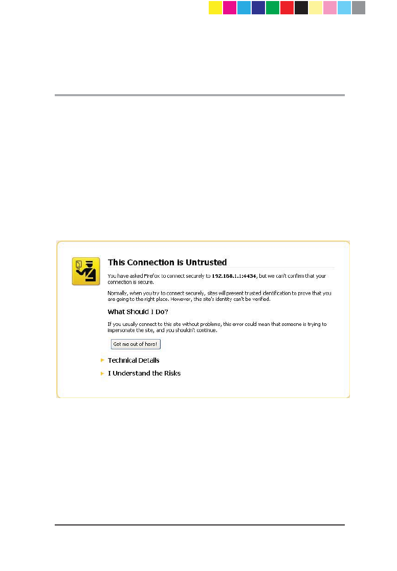
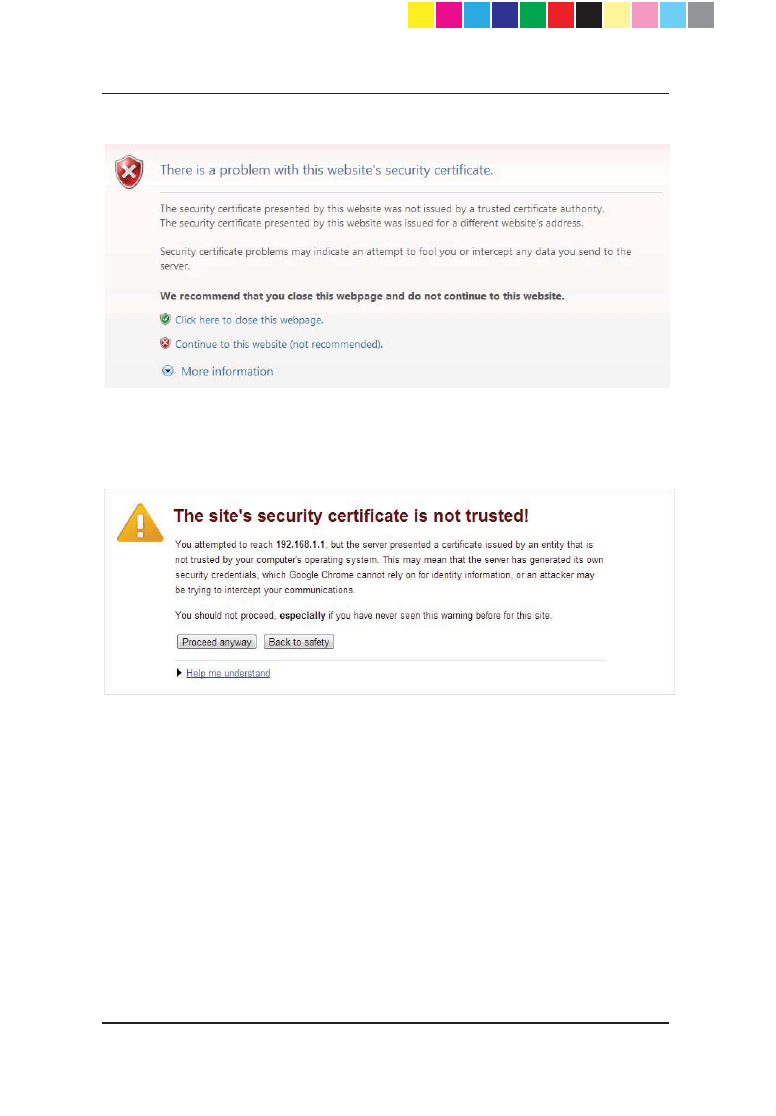
When you log in to the appliance from the Internet Explorer, Mozilla FireFox, or
Google Chrome browser you might see a security warning.
You can safely confirm the warning and continue to log in as usual.
Mozilla FireFox
1. Click I understand the Risks.
2. Click Add Exception. The Add Security Exception dialog box opens.
3. Click Confirm Security Exception.
CP_1100Appliance_GettingStartedG59 59CP_1100Appliance_GettingStartedG59 59 25/02/2013 10:05:3025/02/2013 10:05:30
Page 60
Internet Explorer
Click Continue to this website (not recommended).
Google Chrome
Click Proceed anyway.
CP_1100Appliance_GettingStartedG60 60CP_1100Appliance_GettingStartedG60 60 25/02/2013 10:05:3025/02/2013 10:05:30
Page 61
Chapter 6
Appendix B: Security
Management Issues
In This Chapter
Viewing the Policy Installation Status
Configuring Notification Settings
Viewing the Policy Installation
Status
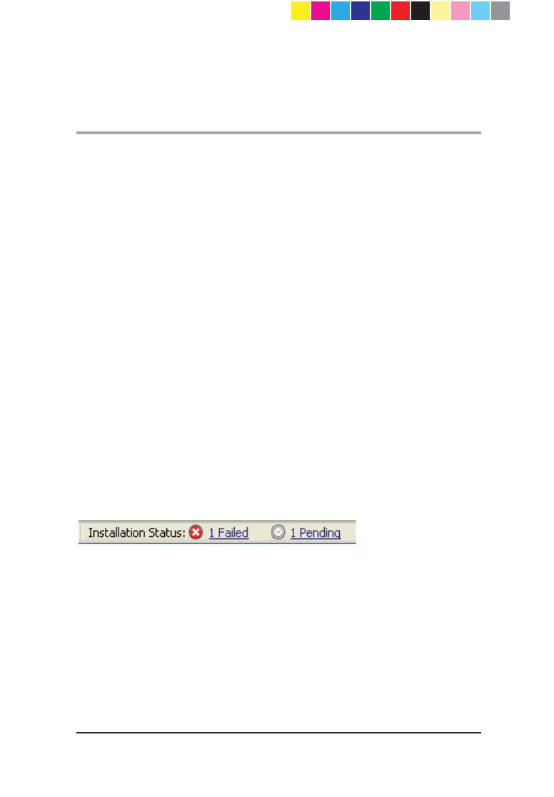
You can see the installation status of managed gateways with the status bar
that shows at the bottom of the SmartDashboard window. The status bar
shows how many gateways are in Pending or Failed mode.
x Pending - gateways that are in the waiting for first connection status or are
in the pending status (see below for detailed explanations).
x Failed - gateways that have failed to install the policy.
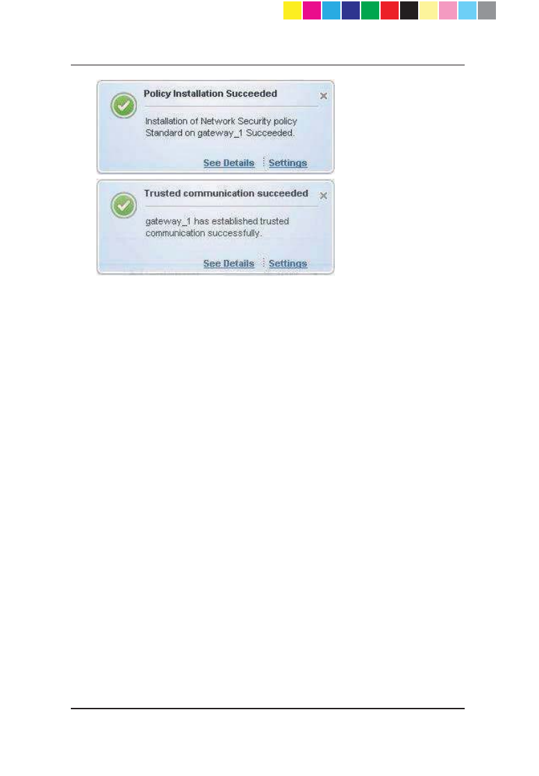
The status bar is updated dynamically each time a gateway tries to install a
policy or tries to connect to the Security Management server. The results of
these actions are also shown in SmartDashboard popup notification balloons
when such events occur. You can configure these notifications ("Configuring
Notification Settings " on page 65).
To monitor the status of the last policy installed on each gateway, you can use
the Policy Installation Status window.
The window has two sections. The top section shows a list of gateways and
status details regarding the installed policy. You can use the filter fields to see
only policies of interest and hide other details by defining the applicable criteria
for each field. After you apply the filtering criteria, only entries that match the
CP_1100Appliance_GettingStartedG61 61CP_1100Appliance_GettingStartedG61 61 25/02/2013 10:05:3025/02/2013 10:05:30
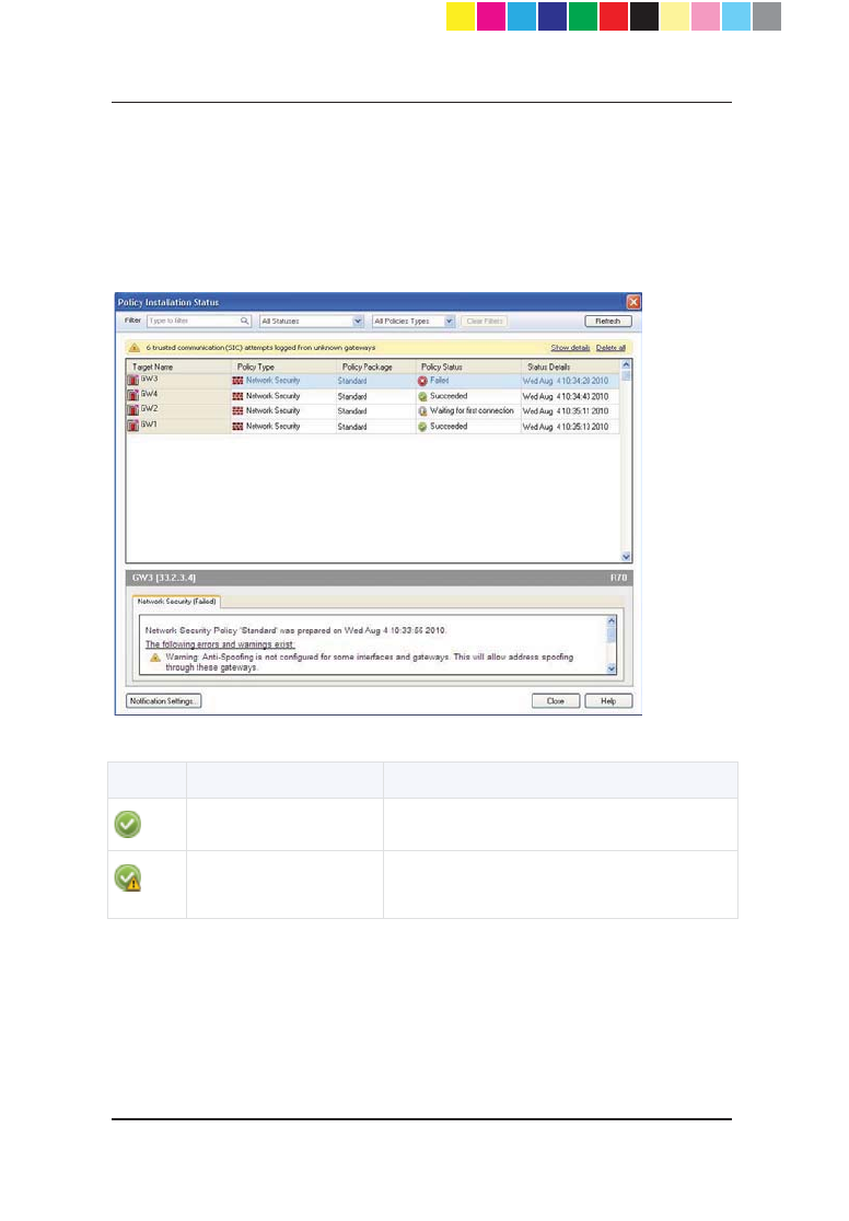
Page 62
selected criteria are shown. If the system logs trusted communication (SIC)
attempts from unknown gateways, a yellow status bar opens below the filter
fields.
The bottom section shows details of a row you select in the gateway list (errors
that occurred, the date the policy was prepared, verification warnings). If there
is a yellow status bar, clicking Show details shows the details of unknown
gateways trying to connect to the Security Management Server.
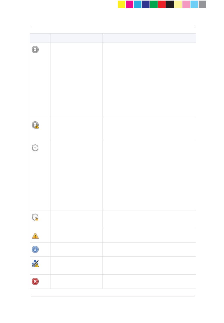
These are the different statuses in this window:
Icon Policy status Description
Succeeded Policy installation succeeded.
Succeeded
Policy installation succeeded but there are
verification warnings.
CP_1100Appliance_GettingStartedG62 62CP_1100Appliance_GettingStartedG62 62 25/02/2013 10:05:3025/02/2013 10:05:30
Page 63
Icon Policy status Description
Waiting for first
connection
When a Check Point 1100 Appliance object
has been configured, but initial trust has not
been established (the gateway has not yet
connected to the Security Management
Server).
x If a policy has been prepared, upon
successful connection, the policy will
be pulled.
x If a policy was not prepared, the Policy
Type column shows "No Policy
Prepared" and upon first connection
only trust is established.
Waiting for first
connection
Same as above but there are warnings that
show attempts to establish trust that failed
or there are verification warnings.
Pending
The policy remains in the pending status
until the Gateway successfully connects to
the Security Management server and
retrieves the policy. This status is shown
only if there was at least one successful
policy installation.
For example, when the Security
Management server has problems
connecting to the Gateway (the Gateway is
unavailable for receiving communication, as
in behind NAT).
Pending Same as above but there are verification
warnings.
Warning Warning.
Information Information.
Failed Policy not installed due to a verification
error.
Failed Policy installation failed.
CP_1100Appliance_GettingStartedG63 63CP_1100Appliance_GettingStartedG63 63 25/02/2013 10:05:3125/02/2013 10:05:31

Page 64
You can access the Policy Installation Status window in these ways:
x From the menu bar - click Policy > Policy Installation Status.
x From the toolbar - click the Policy Installation Status icon
x From the status bar - click on the Failed or Pending link. The contents of
the Policy Installation Status window are shown filtered according to the
link clicked.
x From notification balloons - click the See Details link in the balloon.
CP_1100Appliance_GettingStartedG64 64CP_1100Appliance_GettingStartedG64 64 25/02/2013 10:05:3125/02/2013 10:05:31
Page 65
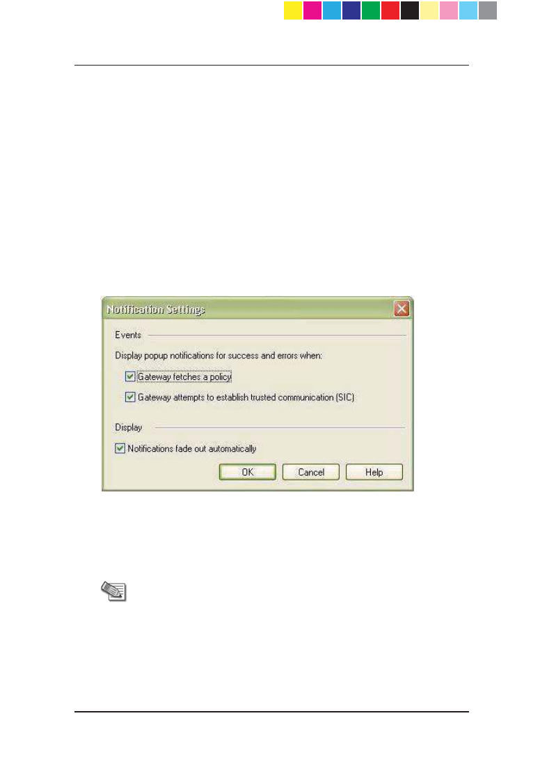
Configuring Notification
Settings
The status bar is updated each time a gateway tries to install a policy or tries to
connect to the Security Management Server. You can also configure a popup
notification balloon to open in SmartDashboard. You can configure the types of
events shown and how notification balloons are shown. By default, notification
balloons stay open until they are manually closed.
To configure notification settings:
1. From the Policy Installation Status window, click Notification Settings
or
From a notification balloon, click Settings.
2. To show trials of installing a policy, select Gateway fetches a policy.
3. To show trials of connecting to the Security Management Server, select
Gateway attempts to establish trusted communication (SIC).
4. To set the notifications to pop-up momentarily in SmartDashboard and
then fade out, select Notifications fade out automatically.
Note - If you do not select the Notifications fade out
automatically check box, notifications will stay open
until you manually close them.
CP_1100Appliance_GettingStartedG65 65CP_1100Appliance_GettingStartedG65 65 25/02/2013 10:05:3125/02/2013 10:05:31
Page 66
CP_1100Appliance_GettingStartedG66 66CP_1100Appliance_GettingStartedG66 66 25/02/2013 10:05:3125/02/2013 10:05:31

Index
A
$GPLQLVWUDWRU$FFHVV
37
Appendix A
Browser Security
:DUQLQJV
Appendix B
Security Management
,VVXHV
$SSOLDQFH$FWLYDWLRQ
Appliance Date and Time
6HWWLQJV
$SSOLDQFH1DPH
$XWKHQWLFDWLRQ'HWDLOV
29
B
%DFN3DQHO
C
Centrally Managed -
Security Management
6HUYHU$XWKHQWLFDWLRQ
41
Centrally Managed -
Security Management
6HUYHU&RQQHFWLRQ
Check Point 1100
$SSOLDQFH+DUGZDUH
47
Check Point 1100
$SSOLDQFH2YHUYLHZ
13
Configuring Check Point
$SSOLDQFH
Configuring Notification
6HWWLQJV
&RQQHFWLQJWKH&DEOHV
26
D
Defining a SmartLSM
ProfLOH
Defining the Object in
6PDUW'DVKERDUG
Deploying with
6PDUW3URYLVLRQLQJ
F
)URQW3DQHO
G
*ORVVDU\
H
Health and Safety
,QIRUPDWLRQ
I
,QWHUQHW&RQQHFWLRQ
,QWURGXFWLRQ
L
Large-scale Deployment
/RFDO1HWZRUN
M
0DQDJHPHQW2SWLRQV
15
CP_1100Appliance_GettingStartedG67 67CP_1100Appliance_GettingStartedG67 67 25/02/2013 10:05:3125/02/2013 10:05:31

P
Predefining a Centrally
Managed Deployment
Preparing to Install the
6HFXULW\3ROLF\
R
Recommended Workflow
Restoring Factory
'HIDXOWV
S
Security Gateway
6RIWZDUH%ODGHV
Security Policy
0DQDJHPHQW
Setting Up the Check
3RLQW$SSOLDQFH
26
Shipping Carton
&RQWHQWV
Small-scale Deployment
Starting the First Time
&RQILJXUDWLRQ:L]DUG
27
6XPPDU\
6XSSRUW
Support and Further
,QIRUPDWLRQ
T
This Getting Started
Guide Includes
U
Using the First Time
&RQILJXUDWLRQ:L]DUG
27
V
Viewing the Policy
,QVWDOODWLRQ6WDWXV
W
:HOFRPH
:KHUH7R)URP+HUH"
55
Wireless Network (for
Wireless Network
0RGHOV
CP_1100Appliance_GettingStartedG68 68CP_1100Appliance_GettingStartedG68 68 25/02/2013 10:05:3125/02/2013 10:05:31
Qbhf!7:!
!
Qbhf81!