Checkpoint Systems FISOLRR RFID Transponder Reader System User Manual ILS 3 0 Installation Manual
Checkpoint Systems Inc RFID Transponder Reader System ILS 3 0 Installation Manual
UserManual.wiki
>
Checkpoint Systems
>
FISOLRR User Manual
User Manual
Navigation menu
Upload a User Manual
Namespaces
Wiki Guide
HTML
PDF
Info
Views
User Manual
Discussion / Help
Navigation
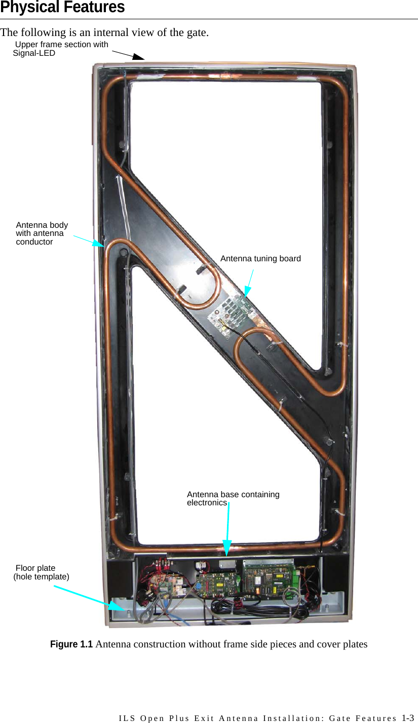
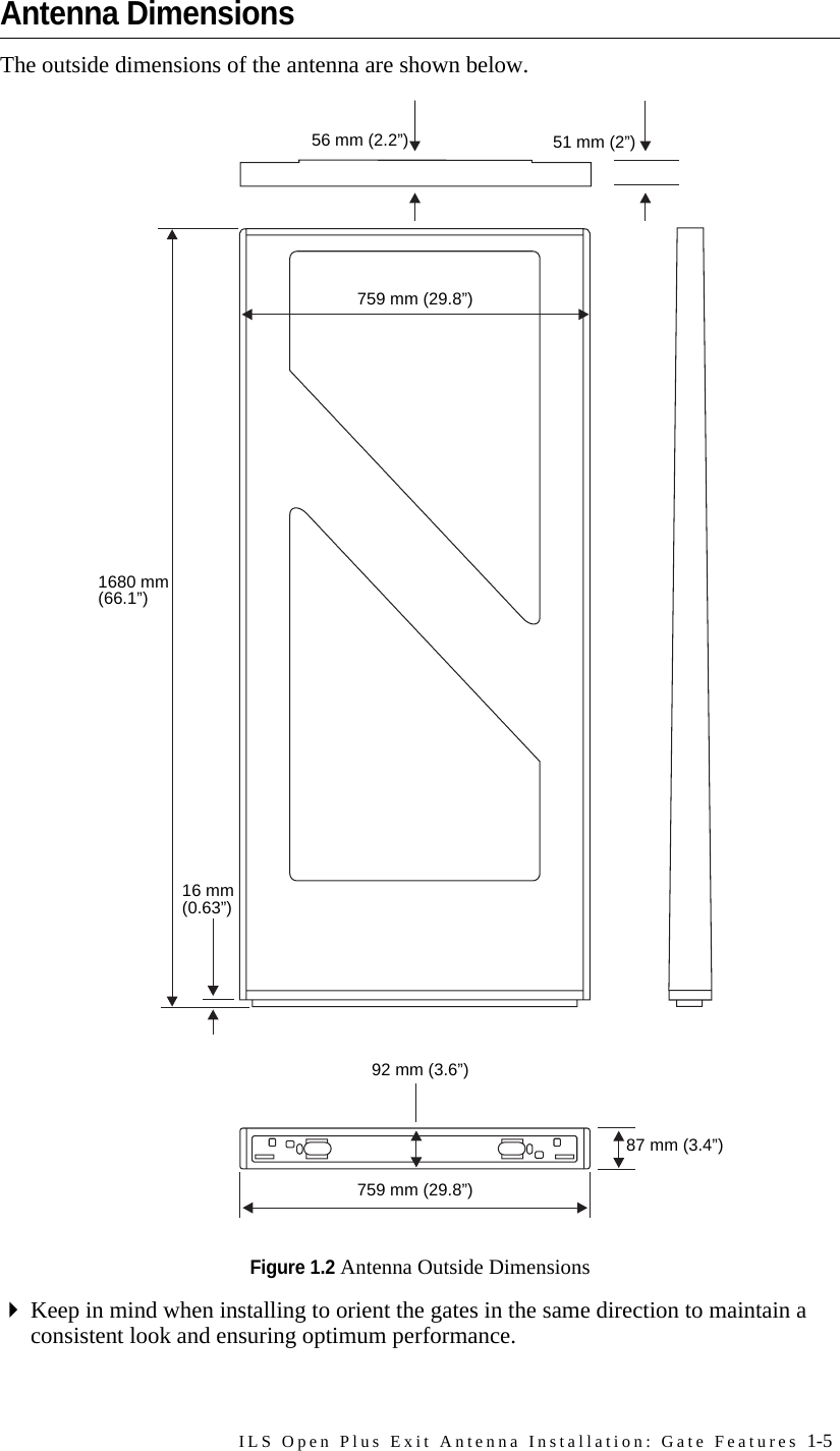
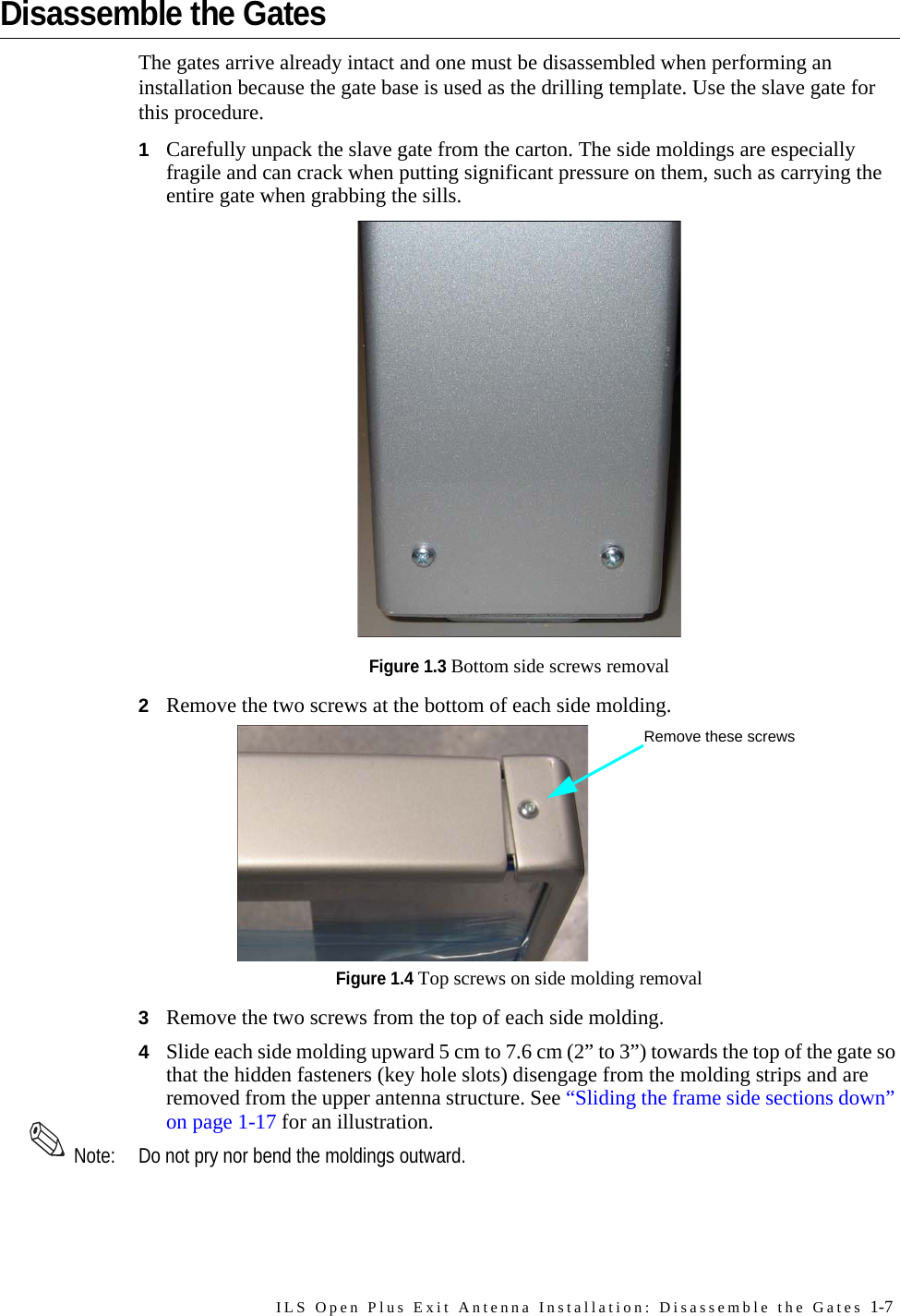
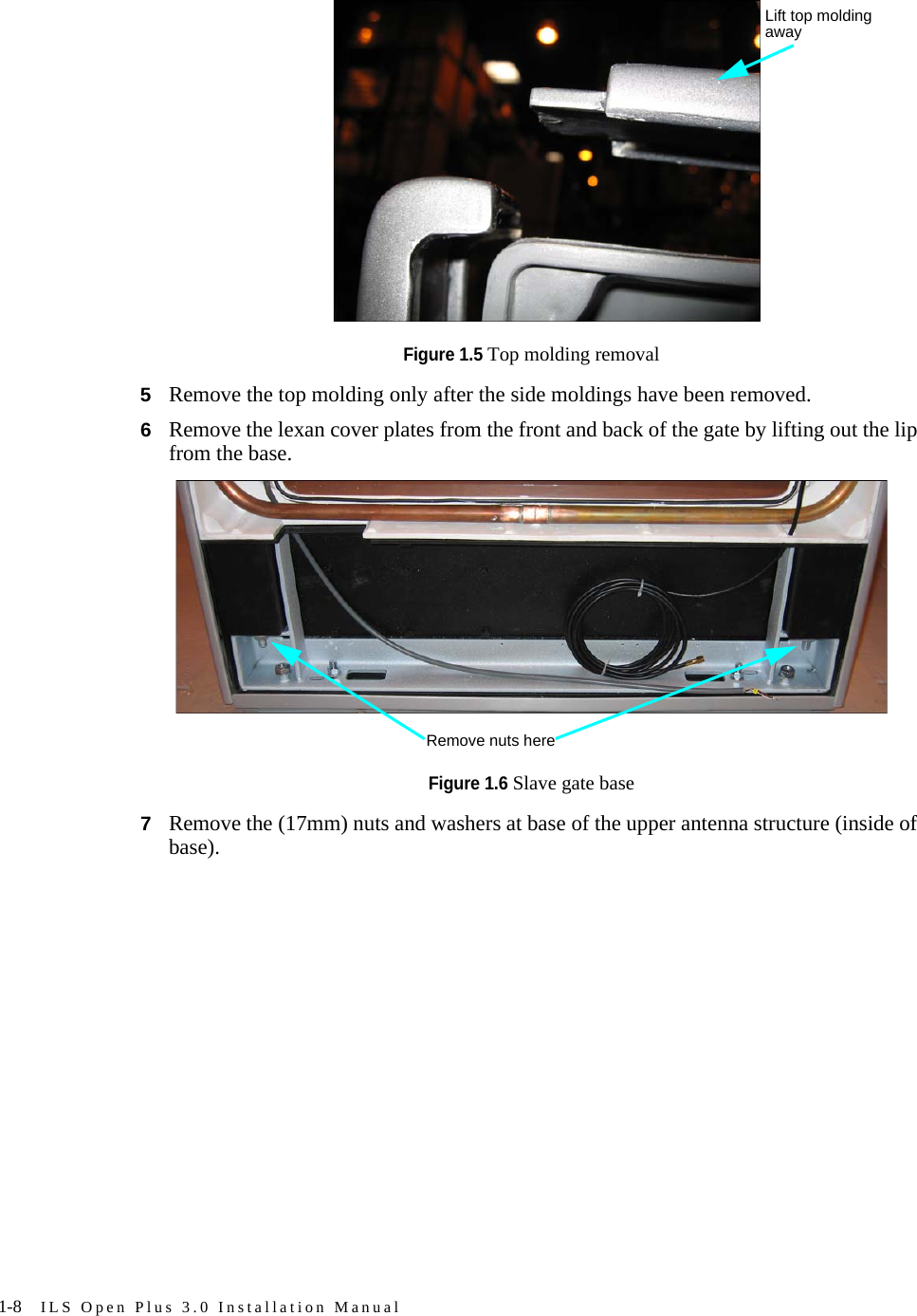
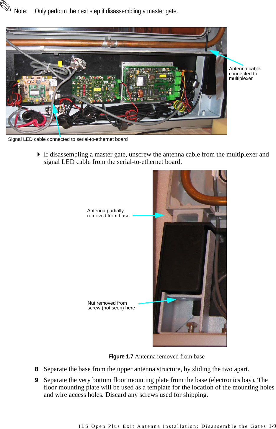
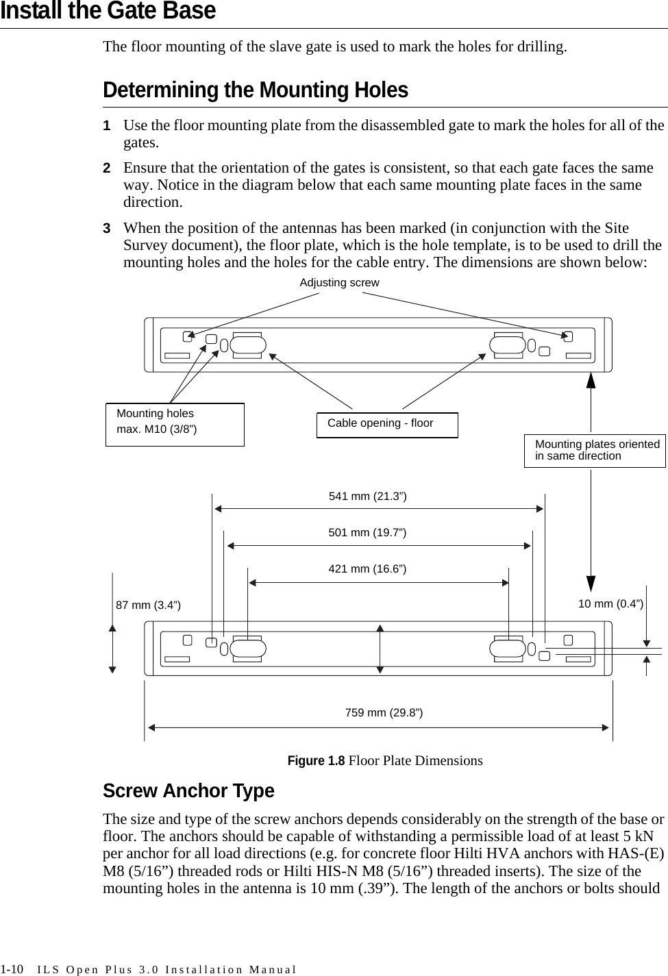
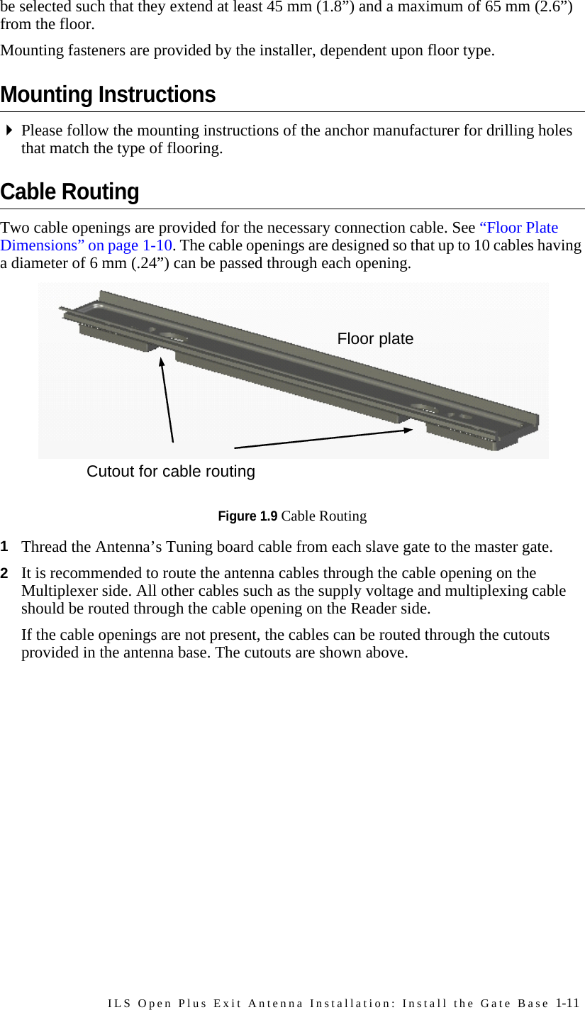
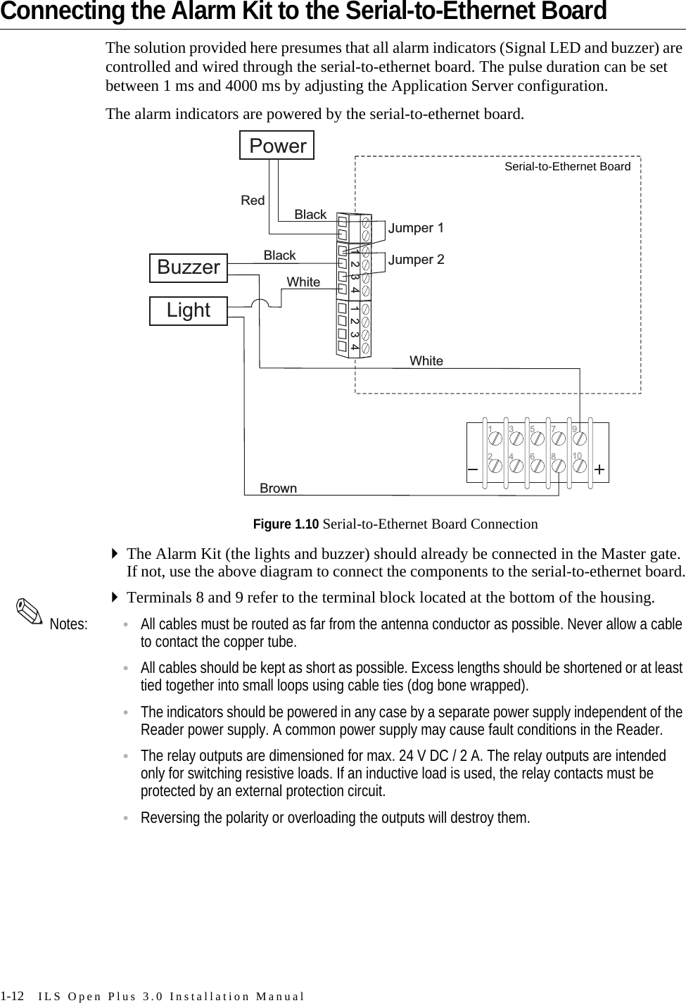
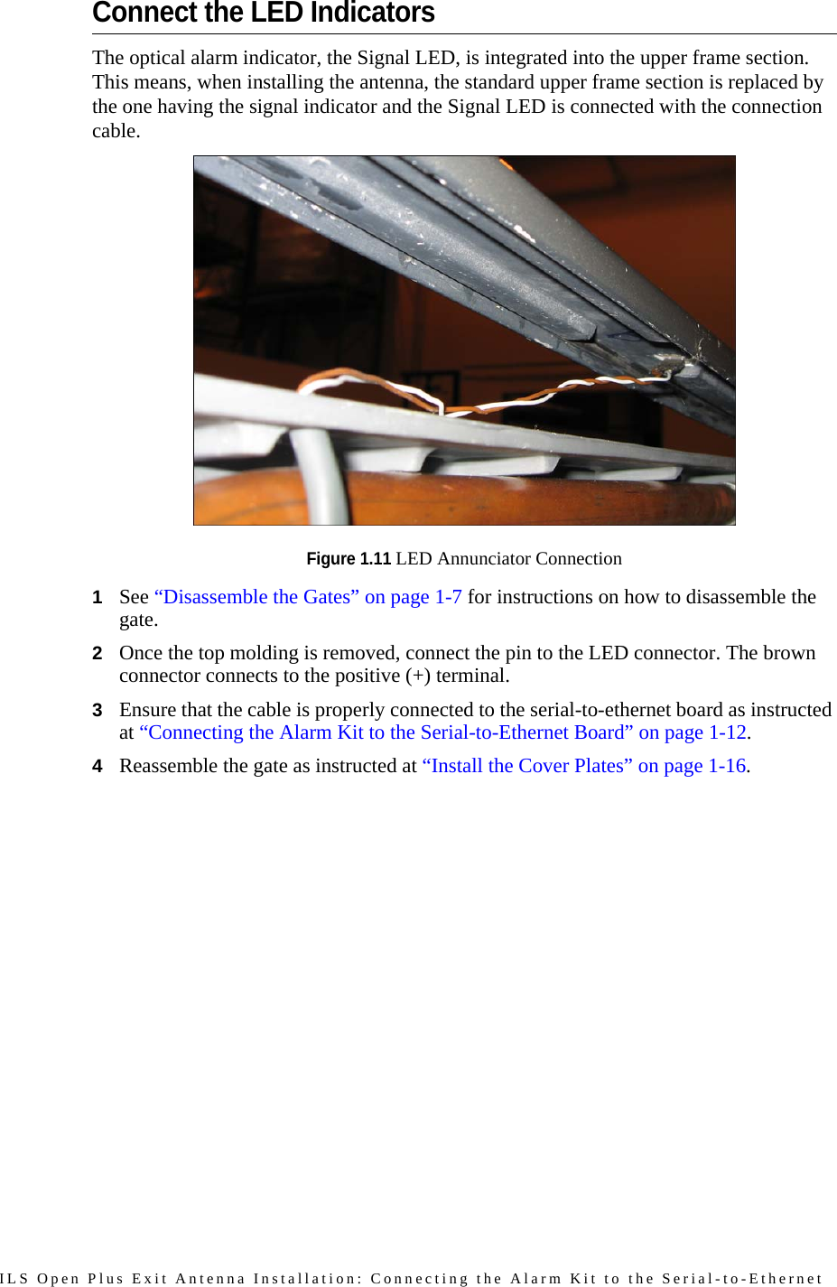
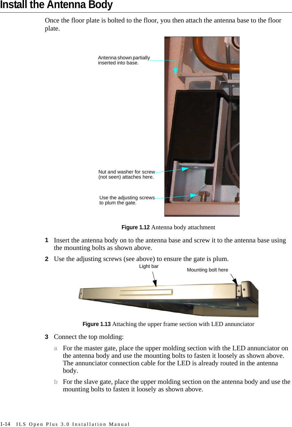
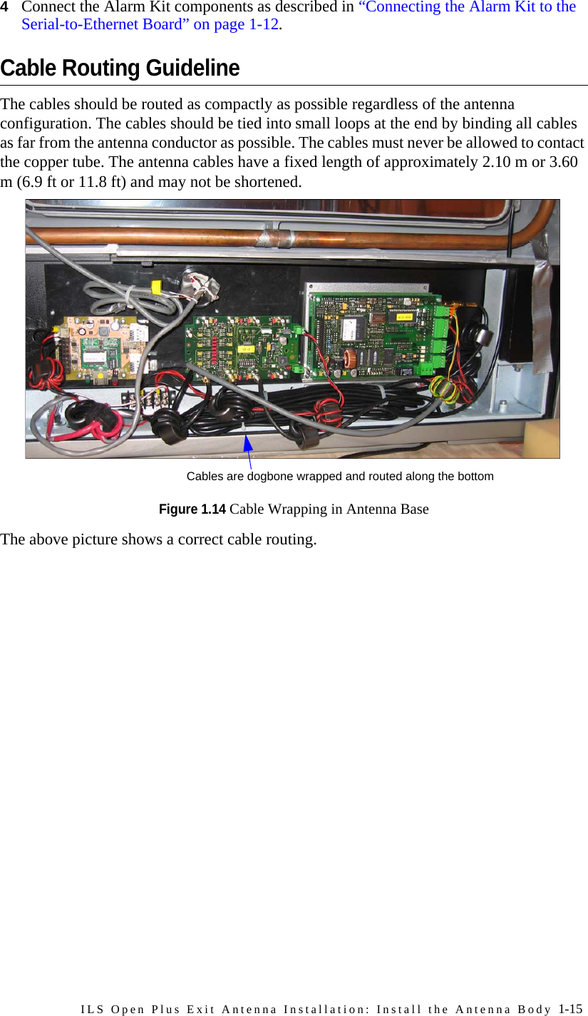
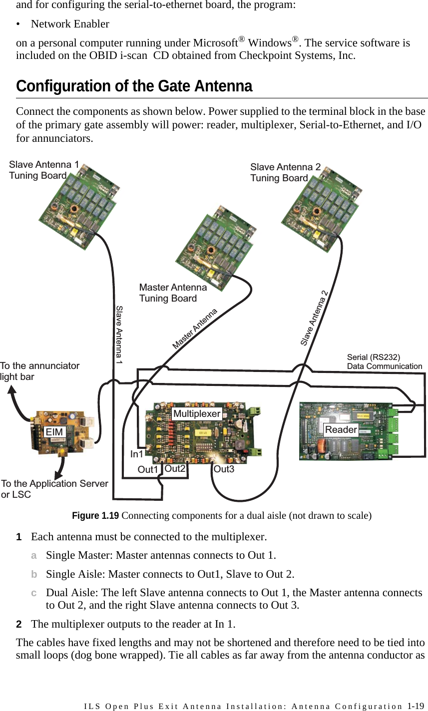
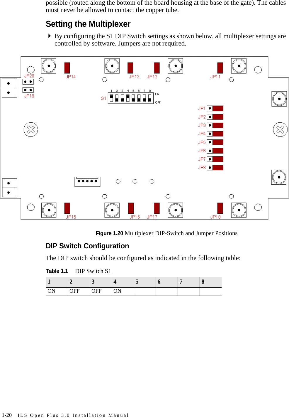
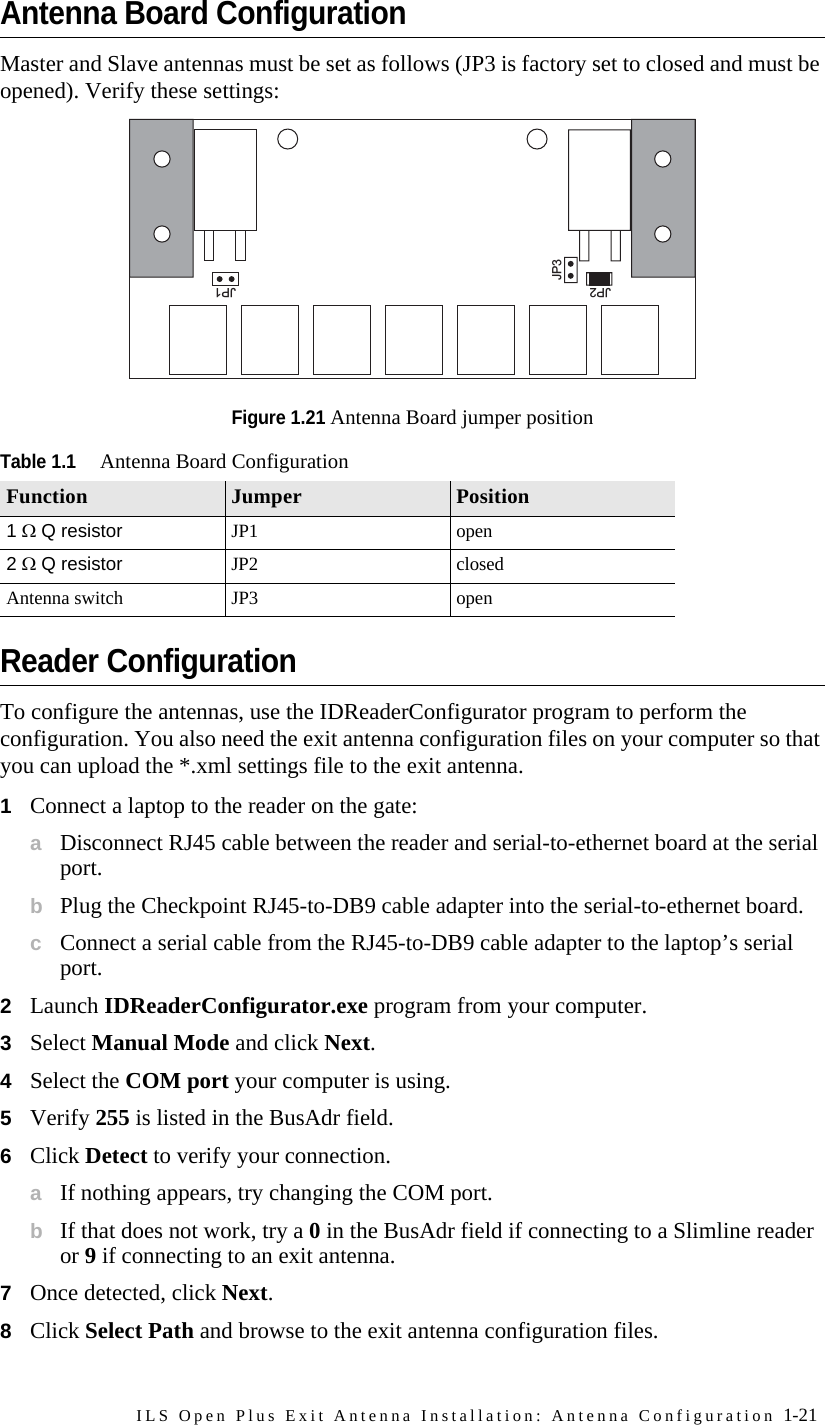
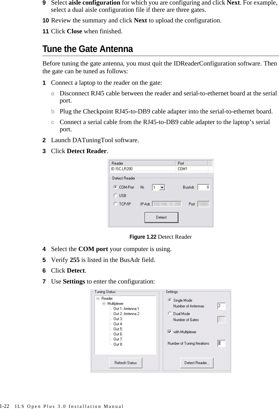
![1-6 ILS Open Plus 3.0 Installation ManualSite SurveyA site survey document should already have been completed for the intended installation. Refer to the site survey document for details regarding physical installation, proper grounding, proper electrical connections, etc.Aisle WidthThe spacing of the gates depends upon the gate configuration, but the maximum aisle width distance (centerline to centerline) is 91 cm (36”), and minimum of 81.5 cm (32”). Widths narrower than 81.5 cm (32”) does not meet ADA guidelines. The gate base should be installed first as it provides the template necessary for securing the gate to the floor. See “Determining the Mounting Holes” on page 1-10 to begin. Gate Area RequirementsFor maximum performance, the gates should have a clearance of at least 50 cm (19.7”) between the antenna and objects that impact RF performance (such as metal). Otherwise, the Reader range will be significantly reduced. At a minimum, the gates must have at least a clearance of 20 cm (7.9”) clearance on all sides. OrientationThe orientation of the gates should be determined and then maintained consistently between multiple gate antennas across the adjacent aisles. This results in the electronics bays all facing the same direction.Multiple Gate ScenarioIf multiple sets (one primary and up to 2 secondary) of gates are used, a minimum separation of 8 m (26.2 ft) must be kept between the antennas or gates. For shorter distances (1 m - 8 m [9.8 ft - 26.2 ft]) the Readers must be synchronized; otherwise the Reader range will be significantly reduced.](https://usermanual.wiki/Checkpoint-Systems/FISOLRR/User-Guide-624313-Page-12.png)