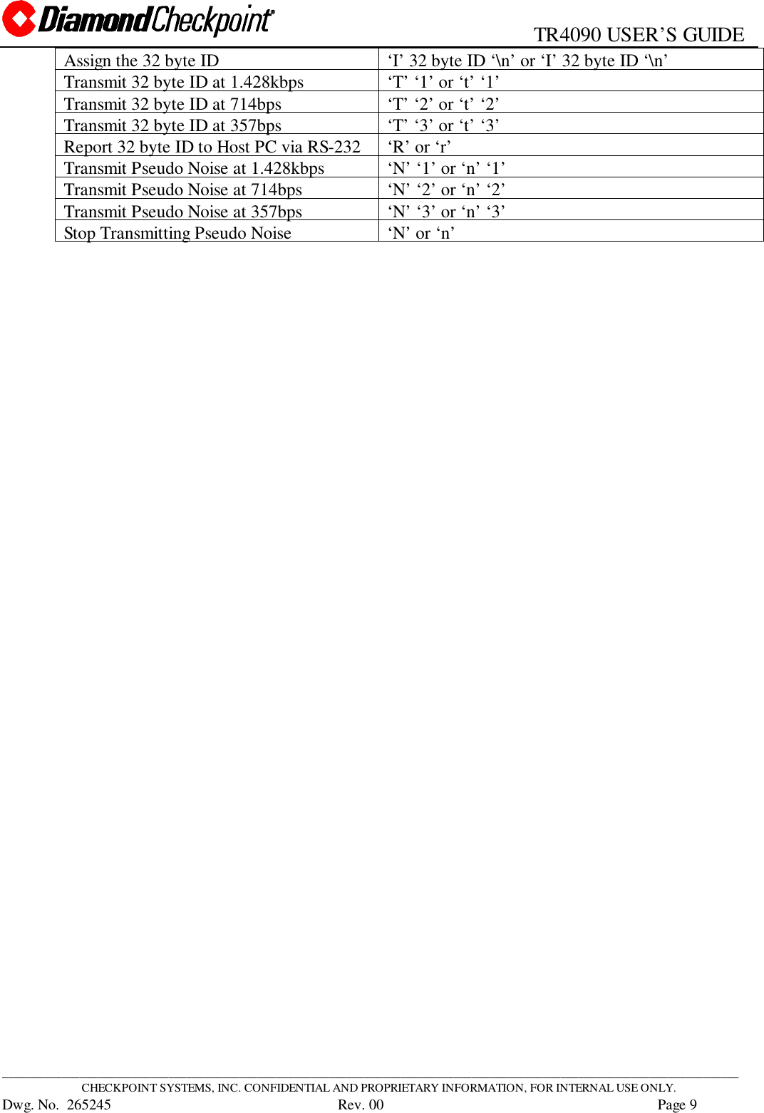
Checkpoint Systems GPRO7000 General Purpose Reader User Manual GRPO usersguide

Checkpoint Systems Inc General Purpose Reader GRPO usersguide

GRPO usersguide

265245 NOTICE TO PERSONS RECEIVING THIS DRAWINGAND/OR TECHNICAL INFORMATION:Title: TR4090 USER’S GUIDECheckpoint Systems claims proprietary rights to the material disclosed hereon.This drawing and/or technical information is issued in confidence for engineeringinformation only and may not be reproduced or used to manufacture anythingshown or referred to hereon without direct written permission from CheckpointSystems to the user. This drawing and/or technical information is the propertyof Checkpoint Systems and is loaned for mutual assistance, to be returnedwhen its purpose has been served.THIS DRAWING AND/OR TECHNICAL INFORMATION IS THEPROPERTY OF CHECKPOINT SYSTEMS, INC.Revisions RevisionsRev Description Date Engineer Rev Description Date ApprovedDoc Spec.: Date:Dwn: P. WILHELM Date: 9/13/00Chk: Date:Eng: P.WILHELM Date: 9/13/00 Size A 265245Used On Appd: Date: Scale: N/A  2000 Checkpoint Systems, Inc. Page 1     of  9
                                                  TR4090 USER’S GUIDE____________________________________________________________________________________________________________________________CHECKPOINT SYSTEMS, INC. CONFIDENTIAL AND PROPRIETARY INFORMATION, FOR INTERNAL USE ONLY.Dwg. No.  265245      Rev. 00 Page 2TABLE OF CONTENTS1.0 OVERVIEW.........................................................................................................................................32.0 INSTALLING THE TR4090................................................................................................................33.0 SERIAL DATA FORMATS.................................................................................................................43.1   BCH-ENCODED DATA...................................................................................................................................................53.2   12-BYTE ASCII DATA.....................................................................................................................................................53.3   15-BYTE ASCII DATA.....................................................................................................................................................54.0 CONVERTING ASCII REPRESENTATION TO BINARY................................................................65.0 BAUD RATE SELECTION COMMANDS.........................................................................................66.0 ONLINE REQUEST COMMAND.......................................................................................................77.0 COMMANDS FOR TELEC USE.........................................................................................................77.1   TRANSMITTER IDENTIFICATION NUMBER...............................................................................................................77.1.1   Assigning And Storing The 32-byte ID...................................................................................................................... 77.1.2   RF Transmitting The 32-byte ID............................................................................................................................... 77.1.3   Reporting The 32-byte ID..........................................................................................................................................87.2   PSEUDO NOISE TRANSMITTER ...................................................................................................................................87.2.1   Generating/Transmitting The Pseudo Noise............................................................................................................. 8
                                                  TR4090 USER’S GUIDE____________________________________________________________________________________________________________________________CHECKPOINT SYSTEMS, INC. CONFIDENTIAL AND PROPRIETARY INFORMATION, FOR INTERNAL USE ONLY.Dwg. No.  265245      Rev. 00 Page 31.0 OVERVIEWThe TR4090’s function is to “read” MCRF355 passive read-only RFID tags.  The MCRF355provides 154 bits of non-volatile user memory.  When the MCRF355 enters the RF field of theTR4090, it is in a tuned state.  The tuned circuit of the tag resonates with the continuous RF fieldof the TR4090 antenna and therefore gathers energy.  The tag stores enough energy to keep thetag circuit powered long enough to transmit its 154 bits of data.  The tag’s data is transmitted inManchester format at a nominal frequency of 70kHz +/- 12kHz.The tag transmits its data by tuning and detuning its resonant circuit.  When the RF tag is tuned, itloads (takes energy from) the reader field.  The loading of the reader field shows up as smallamplitude perturbations of the RF reader’s field (back scatter).  These perturbations are at 70kHzand so are easily filtered out of the 13.56MHz carrier of the field.  The 70kHz base band data isamplified for further processing.  The raw Manchester data is decoded by the TR4090’smicrocontroller and sent out over its RS-232 or RS-485 serial port.The TR4090 connects to a Personal Computer (HOST PC) via its RS-232 or RS-485 serial port.The signal type must be factory set; i.e., the factory default setting is RS-232 but can be changedto RS-485 by appropriate jumper settings.  When  RFID tag data is received, the data is sent to theHOST PC according to the formats discussed in the next section.In addition to receiving data from the TR4090 via its serial port, the HOST PC can sendcommands to the TR4090 in order to configure it.Commands from the HOST PC must always be sent at 9600 baud in order to avoid conflicts.  TheTR4090 can be commanded by the HOST PC to transmit data at one of four baud rates (thesecommands are explained in section 3.0).2.0 INSTALLING THE TR40902.1  Equipment List
                                                  TR4090 USER’S GUIDE____________________________________________________________________________________________________________________________CHECKPOINT SYSTEMS, INC. CONFIDENTIAL AND PROPRIETARY INFORMATION, FOR INTERNAL USE ONLY.Dwg. No.  265245      Rev. 00 Page 4• TR4090• Wall pack, 12V @ 1A output, 120VAC input• 50 Ohm antenna with BNC connector1.) Connect the BNC connector of the antenna to the TR4090’s BNC connector.2.) Mount the TR4090 and the antenna to suit the application.3.) Plug the jack end of the wall pack into the TR4090.4.) Plug the AC end of the wall pack into a 120VAC outlet.  The TR4090 isready to read tags.3.0 SERIAL DATA FORMATSThe TR4090 automatically reads (no settings required) three tag data formats.  That is, theTR4090 recognizes legal tags by a one byte header that is programmed into the tag with the userdata following.  To see this more clearly, the structure of the tag data for the three formats is asfollows:Blank Tag                                                          154 bits of MemoryBCH DataPreamble Header BCH Encoded User Data Trailer Unused memory0xFF 0x147 126 bits 0x147 0 bits12 Byte Data with CRCPreamble Header User Data CCITT-16 CRC Unused memory0xFF 0x22 12 bytes 2 bytes 26 bits15 Byte Data with CRCPreamble Header User Data CCITT-16 CRC Unused memory0xFF 0x11 15 bytes 2 bytes 2 bitsSince binary data can be difficult to view, the TR4090 converts the tag’s binary data to ASCII forthe 12 Byte data format and for the 15 Byte data format so that the information can be easilyviewed using HyperTerminal for instance.The BCH data format is not converted to ASCII since once encoded, the data is not at allrecognizable as the original data.  Converting this to ASCII therefore has no added benefit.  Inorder to properly view the original data, the data sent by the TR4090 to the HOST PC  must bedecoded by the C function, BCHdecoder(), which is available from Checkpoint.All three formats frame the data with ASCII start and stop characters.  The following sectionsdescribe the manner in which the TR4090 represents the tag’s data.
                                                  TR4090 USER’S GUIDE____________________________________________________________________________________________________________________________CHECKPOINT SYSTEMS, INC. CONFIDENTIAL AND PROPRIETARY INFORMATION, FOR INTERNAL USE ONLY.Dwg. No.  265245      Rev. 00 Page 53.1   BCH-ENCODED DATAIf the tags used are BCH-encoded, the data sent from the TR4090 to the HOST PC via an RS-232serial port will have a start character of an ASCII capital ‘H’, followed by 126 bits of BCH-encoded binary data, and an end character which is an ASCII capital ‘N’.For example, the data read by the Reader will be of the form:Preamble Header BCH Encoded User Data Trailer Unused memory0xFF 0x147 126 bits 0x147 0 bitsand the data sent out by the Reader to the HOST will be of the form:ASCII Start Charcter Header, BCH Encoded User Data, Trailer ASCII End Character Total Bytes Sent toHOST‘H’ 146 bits + 6 padded 0s (19 bytes) ‘N’ 21 bytes3.2   12-BYTE ASCII DATAIf the tags used have the 12 byte data format, the data sent from the TR4090 to the HOST PC viaan RS-232 serial port will have a start character of an ASCII capital ‘T’, followed by 24 bytes ofASCII data, and an end character which is an ASCII capital ‘N’.  All characters are thereforeASCII and so can easily be viewed using HyperTerminal for example.Note:  The 24 bytes of ASCII data are the result of converting each nibble that make up the 12bytes of tag data to ASCII.For example, the data read by the Reader will be of the form:Preamble Header User Data CCITT-16 CRC Unused memory0xFF 0x22 12 bytes 2 bytes 26 bitsand the data sent out by the Reader to the HOST will be of the form:ASCII Start Charcter User Data ASCII End Character Total Bytes Sent toHOST‘T’ 24 bytes ‘N’ 26 bytesExample:Contents of  Tag in binary formPreamble Header User Data CCITT-16 CRCFF 22 01  23  45  67  89  AB  CD  EF  AA  BB  CC  DD 6B 07The data sent out by the Reader to the HOST will be:ASCIIStartCharcter24 Bytes of User Data in ASCII representation ASCII EndCharacter‘T’ ‘0’ ‘1’ ‘2’ ‘3’ ‘4’ ‘5’ ‘6’ ‘7’ ‘8’ ‘9’ ‘A’ ‘B’ ‘C’ ‘D’ ‘E’ ‘F’ ‘A’ ‘A’ ‘B’ ‘B’ ‘C’ ‘C’ ‘D’‘D’ ‘N’3.3   15-BYTE ASCII DATAIf the tags used have the 15 byte data format, the data sent from the TR4090 to the HOST PC viaan RS-232 serial port will have a start character of an ASCII capital ‘X’, followed by 30 bytes of
                                                  TR4090 USER’S GUIDE____________________________________________________________________________________________________________________________CHECKPOINT SYSTEMS, INC. CONFIDENTIAL AND PROPRIETARY INFORMATION, FOR INTERNAL USE ONLY.Dwg. No.  265245      Rev. 00 Page 6ASCII data, and an end character which is an ASCII  capital ‘N’.  All characters are thereforeASCII and so can easily be viewed using HyperTerminal for example.For example, the data read by the Reader will be of the form:Preamble Header User Data CCITT-16 CRC Unused memory0xFF 0x11 15 bytes 2 bytes 2 bitsand the data sent out by the Reader to the HOST will be of the form:ASCII Start Charcter User Data ASCII End Character Total Bytes Sent toHOST‘X’ 30 bytes ‘N’ 32 bytes4.0 CONVERTING ASCII REPRESENTATION TO BINARYTo convert from ASCII to BINARY, the HOST PC should subtract 0x30 for characters between‘0’ and ‘9’, and should subtract 0x37 for characters between ‘A’ and ‘F’.Note that the values 1010 = 0xA through 1111 = 0xF are converted by the reader to UPPERCASE ‘A’ through ‘F’ and so 0x37 must be subtracted not 0x57 which corresponds to a lowercase ‘a’.Example:Tag Data:0x1, 0xA, 0x2, 0xB …Data sent by TR4090 to HOST PC:0x31, 0x41, 0x32, 0x42 …To convert to binary:0x31 – 0x30 = 0x1, 0x41 – 0x37 = 0xA, 0x32 – 0x30 = 0x2, 0x42 – 0x37 = 0xB ….5.0 BAUD RATE SELECTION COMMANDSThe rate at which data is transmitted from the TR4090 to the HOST PC is selectable.  The datarate is selected by the HOST PC by sending the following commands to the TR4090 from theHOST PC at 9600 baud:HOST PC Command TR4090 Response – Change Transmit Baud RateTo:“B1\n” or “b1\n” 9600 baud“B2\n” or “b2\n” 19.2k baud“B3\n” or “b3\n” 28.8k baud“B4\n” or “b4\n” 38.4k baudThe TR4090 responds by sending the character string “Baud rate is” followed by the baud ratevalue such as “28.8k”.  This string is sent by the TR4090 to the HOST PC at the new baud rate.Once set, the TR4090 will send tag data to the HOST PC at this data rate.  The data rate is also
                                                  TR4090 USER’S GUIDE____________________________________________________________________________________________________________________________CHECKPOINT SYSTEMS, INC. CONFIDENTIAL AND PROPRIETARY INFORMATION, FOR INTERNAL USE ONLY.Dwg. No.  265245      Rev. 00 Page 7stored in non-volatile memory so that when the TR4090 is turned off and then back on, the lastset data rate will be the data rate at which the TR4090 will transmit tag data.Example: To change the baud rate, at which the TR4090 transmits data, to 28.8k baud, theHOST PC should send the command “B3\n” or “b3\n”.  The TR4090 will thenrespond with the message “Baud rate is 28.8k”.6.0 ONLINE REQUEST COMMANDThe HOST PC can verify that the TR4090 is online by sending an upper case ‘O’ or a lower case‘o’ followed by the new line character ‘\n’.  If the TR4090 is online, it will respond by echoingback the command; i.e., “O\n” or “o\n”.7.0 COMMANDS FOR TELEC USEThe following commands are used to set up the TR4090 for TELEC testing.  These commands aresent by a HOST PC to the TR4090 via an RS-232 serial port.  7.1   TRANSMITTER IDENTIFICATION NUMBERTELEC requires that every RF transmitter have an associated identification number that canbe transmitted on command or on power-up of the device.  In normal operation, the TR4090generates a continuous wave (CW) carrier;  i.e., the transmitter part of the transceiver is notusually modulated.  Nevertheless, TELEC requires field measurements from the transmitterwhen modulating.  Therefore, the following functionality has been added for TELEC testing.The modulation is 1 of 16 pulse-position-modulation (PPM) with the start pulse beinginterpreted as zero.7.1.1   Assigning And Storing The 32-byte IDAn upper case ‘I’ or lower case ‘i’ is sent first, followed by a 32 byte identificationnumber, followed by a new line character ‘\n’.  The 32 byte ID is stored in non-volatile memory so that the TR4090 can be powered down without losing its IDnumber.7.1.2   RF Transmitting The 32-byte IDAn upper case ‘T’ or lower case ‘t’ is sent first, followed by an ASCII ‘1’ tocommand the TR4090 to transmit (amplitude modulate the carrier) its identificationnumber at a data rate of  1.428kbps.  This should not be confused with transmittingdata over the serial port; i.e., the ‘t’ refers to an RF transmission.The symbol rate is therefore 1 symbol/2.8msec which gives 175usec/pulse position.The pulse width is ½ the pulse position time which is 88usec.An upper case ‘T’ or lower case ‘t’ is sent first, followed by an ASCII ‘2’ tocommand the TR4090 to transmit (amplitude modulate the carrier) its identificationnumber at a data rate of  714bps.The symbol rate is therefore 1 symbol/5.6msec which gives 350usec/pulse position.The pulse width is ½ the pulse position time which is 175usec.
                                                  TR4090 USER’S GUIDE____________________________________________________________________________________________________________________________CHECKPOINT SYSTEMS, INC. CONFIDENTIAL AND PROPRIETARY INFORMATION, FOR INTERNAL USE ONLY.Dwg. No.  265245      Rev. 00 Page 8An upper case ‘T’ or lower case ‘t’ is sent first, followed by an ASCII ‘3’ tocommand the TR4090 to transmit (amplitude modulate the carrier) its identificationnumber at a data rate of  357bps.The symbol rate is therefore 1 symbol/11.2msec which gives 700usec/pulseposition.  The pulse width is ½ the pulse position time which is 350usec.7.1.3   Reporting The 32-byte IDAn upper case ‘R’ or lower case ‘r’ is sent by the HOST PC to command theTR4090 to report its identification number back to the HOST PC via the RS-232serial port.7.2   PSEUDO NOISE TRANSMITTERThe pseudo noise transmitter is a TELEC requirement.  The pseudo noise polynomial is1 + X14 + X15.   The pseudo noise is a pseudo-random sequence of 1 of 16 PPM data.The following commands are used to start the pseudo noise generator.  NOTE: TAGSCANNOT BE READ WHILE TRANSMITTING PSEUDO NOISE.7.2.1   Generating/Transmitting The Pseudo NoiseAn upper case ‘N’ or lower case ‘n’ is sent by the HOST PC, followed by an ASCII‘1’, to command the TR4090 to transmit (amplitude modulate the carrier) a“random” sequence of PPM data at a rate of 1.428kbps. The symbol rate istherefore 1 symbol/2.8msec which gives 175usec/pulse position.  The pulse width is½ the pulse position time which is 88usec.The pseudo noise data stream will be continuously transmitted until the command isgiven to stop transmitting.  An ASCII ‘N’ or ‘n’ is sent to STOP the pseudo noisegenerator.  The TR4090 will then be ready to read tag data without having to restartthe GPR.An upper case ‘N’ or lower case ‘n’ is sent by the HOST PC, followed by an ASCII‘2’, to command the TR4090 to transmit (amplitude modulate the carrier) a“random” sequence of PPM data at a rate of 714bps.  The symbol rate is therefore1 symbol/5.6msec which gives 350usec/pulse position.  The pulse width is ½ thepulse position time which is 175usec.An ASCII ‘N’ or ‘n’ is sent to STOP the pseudo noise generator.An upper case ‘N’ or lower case ‘n’ is sent by the HOST PC, followed by an ASCII‘3’, to command the TR4090 to transmit (amplitude modulate the carrier) a“random” sequence of PPM data at a rate of 357bps. The symbol rate is therefore 1symbol/11.2msec which gives 700usec/pulse position.  The pulse width is ½ thepulse position time which is 350usec.An ASCII ‘N’ or ‘n’ is sent to STOP the pseudo noise generator.Summary of Commands For Transmitting ID and Pseudo NoiseNote: All commands are in ASCII format so that ‘1’ = 0x31 for example.ACTION HOST PC Command
                                                  TR4090 USER’S GUIDE____________________________________________________________________________________________________________________________CHECKPOINT SYSTEMS, INC. CONFIDENTIAL AND PROPRIETARY INFORMATION, FOR INTERNAL USE ONLY.Dwg. No.  265245      Rev. 00 Page 9Assign the 32 byte ID ‘I’ 32 byte ID ‘\n’ or ‘I’ 32 byte ID ‘\n’Transmit 32 byte ID at 1.428kbps ‘T’ ‘1’ or ‘t’ ‘1’Transmit 32 byte ID at 714bps ‘T’ ‘2’ or ‘t’ ‘2’Transmit 32 byte ID at 357bps ‘T’ ‘3’ or ‘t’ ‘3’Report 32 byte ID to Host PC via RS-232 ‘R’ or ‘r’Transmit Pseudo Noise at 1.428kbps ‘N’ ‘1’ or ‘n’ ‘1’Transmit Pseudo Noise at 714bps ‘N’ ‘2’ or ‘n’ ‘2’Transmit Pseudo Noise at 357bps ‘N’ ‘3’ or ‘n’ ‘3’Stop Transmitting Pseudo Noise ‘N’ or ‘n’

Navigation menu