Checkpoint Systems LIB24TZ Part 15 Anti-Pilferage Device User Manual Confidential Installation Manual rev
Checkpoint Systems Inc Part 15 Anti-Pilferage Device Confidential Installation Manual rev
Contents
- 1. Confidential_Installation Manual_rev
- 2. Manual
Confidential_Installation Manual_rev
P/N: 7149651
PX/QX with Coupler
Installation Manual
Document Version *61

PX/QX with Coupler Installation Manual Version *61
Liberty PX/QX with Coupler Installation Manual
Copyright © 2009 by Checkpoint Systems Inc.
Released September 31, 2009.
Published by:
Checkpoint Systems Inc.
101 Wolf Drive
Thorofare, NJ 08086
Document revision information
PX/QX with Coupler Installation Manual, version 0.0
Rev Description Date Author
*60 9/18/09 Jean Long/Jim Cullen/James Ji
*61 Updated Statement 11/02/09 Jean Long
Trademarks
Checkpoint is a registered trademark of Checkpoint Systems, Inc.
Checkpoint, Liberty, Evolve, and VisiPlus are registered trademarks of Checkpoint Systems, Inc. All rights reserved.
Information in this document is subject to change without notice.
Other products © or ® their respective manufacturers or copyright holders.
Companies, names and data used in examples herein are fictitious unless otherwise noted. No part of the contents of
this book may be reproduced or transmitted in any form or by any means without the written permission of the
publisher.
Copyright and Warranty Information
The information in this document is subject to change without notice.
Because of the changing nature of this product information presented in the PX/QX with Coupler Installation
Manual, Checkpoint Systems, Inc. is not liable for any omissions, misstatements, or other errors of information.
The information presented in this document may not be copied, used or disclosed to others for the purpose of
procurement or manufacturing without the written permission of Checkpoint Systems, Inc. This guide and the
products discussed in this guide are the exclusive property of Checkpoint Systems Inc. Copyright laws of the United
States protect all information and products.
Copyright© 2009 Checkpoint Systems, Inc. All rights reserved.

PX/QX with Coupler Installation Manual Version *61
Statements
• The device(s) may only be used for the intended purpose designed by for the manufacturer.
• Unauthorized changes and the use of spare parts and additional devices which have not been sold or
recommended by the manufacturer may cause fire, electric shocks or injuries. Such unauthorized measures
shall exclude any liability by the manufacturer.
• The liability-prescriptions of the manufacturer in the issue valid at the time of purchase are valid for the
device. The manufacturer shall not be held legally responsible for inaccuracies, errors, or omissions in the
manual or automatically set parameters for a device or for an incorrect application of a device.
• Repairs may only be executed by the manufacturer.
• Installation, operation, and maintenance procedures should only be carried out by qualified personnel.
• Use of the device and its installation must be in accordance with national legal requirements and local
electrical codes.
• When working on devices the valid safety regulations must be observed.
• Before touching the device, the power supply must always be interrupted. Make sure that the device is
without voltage by measuring. The fading of an operation control (LED) is not an indicator for an
interrupted power supply or the device being out of voltage!
• The installer or licensed electrician must follow all NEC and local codes.
• In accordance with article 725 of the NEC, UL will permit a product to be Listed, where Class 2 wiring is
notched in the floor and secured in place by non-water based/ non-corrosive material. Cables shall be
installed in a neat and workman like manner as described in article 725.8. In addition, UL also requires the
following with respect to interpedestal and other wiring from the pedestal. a Not to be installed in Damp or
Wet Locations. For indoor use only. b Wires are not to be embedded in concrete. c Circuits shall be
installed so as to not damage the cable.
• All wires routed in the floor per article 725 must be Class 2 and be UL Listed. UL Recognized AWM may
be employed, provided it is enclosed in Conduit of ENT.
• Inter-pedestal wiring should not be directly installed in wet concrete.
• Inter-pedestal wiring scenarios (either in-floor, in walls, or in ceiling) that meet this UL guidance are
presumed to satisfy UL / cUL Listing requirements.

PX/QX with Coupler Installation Manual Version *61
Important Information to our Users in North America
FCC Regulatory Compliance Statement
Checkpoint Systems, Inc., offers Electronic Article Surveillance (EAS) or Radio Frequency
Identification Products that have been FCC certified or verified to 47 CFR Part 15 Subparts B/C
and/or 47 CFR Part 18. Appropriately, one of the following labels will apply to the approval:
NOTE: This equipment has been tested and found to comply with the limits for a class A digital
device, pursuant to Part 15 of the FCC Rules. These limits are designed to provide reasonable
protection against harmful interference when the equipment is operated in a commercial
environment. This equipment generates, uses, and can radiate interference to radio
communications. Operation of this equipment in a residential area is likely to cause harmful
interference in which case the user will be required to correct the interference at his own expense.
- OR -
This device complies with Part 15 of the FCC Rules. Operation is subject to the following
two conditions: (1) including this device may not cause harmful interference, and (2) this
device must accept any interference received, including interference that may cause
undesired operation, which may include intermittent decreases in detection and/or
intermittent increases in alarm activity.
- OR –
NOTE: This equipment has been tested and found to comply with the limits for a
miscellaneous type ISM device, pursuant to Part 18 of the FCC Rules. This equipment
generates, uses, and can radiate radio frequency energy and, if not installed and used in
accordance with the instruction manual, may cause harmful interference to radio
communications. However, there is no guarantee that interference will not occur in a
particular installation. If this equipment does cause harmful interference to radio
communications reception, which can be determined by turning the equipment off and on,
please contact Checkpoint Systems, Inc., at 1 (800) 257-5540 for further assistance.
Equipment Safety Compliance Statement
Checkpoint Systems’ EAS or Radio Frequency Identification products have been designed to be
safe during normal use and, where applicable, certain components of the system or accessory
sub-assemblies have been certified, listed or recognized in accordance with one or more of the
following Safety standards: UL 1012, UL 1037, UL 1310, UL 60950-1, CSA C22.2 No. 205,
CSA C22.2 No. 220, CSA C22.2 No. 223, CSA C22.2 No. 60950-1. Additional approvals may
be pending.
WARNING: Changes or modifications to Checkpoint’s EAS or Radio Frequency Identification
(RFID) equipment not expressly approved by the party responsible for assuring compliance
could void the user’s authority to operate the equipment in a safe or otherwise regulatory
compliant manner.

PX/QX with Coupler Installation Manual Version *61
Important Information to our Users in Europe
CE Regulatory Compliance Statement
Where applicable, Checkpoint Systems, Inc., offers certain Electronic Article Surveillance (EAS)
products that have CE Declarations of Conformity according to R&TTE Directive 99/5/EC.
System Electromagnetic Compatibility (EMC), has been tested and notified through Spectrum
Management Authorities if necessary, using accredited laboratories, whereby, conformity is
declared by voluntarily accepted European Telecommunications Standards Institute (ETSI)
standards EN 301489-3 and EN 300330-2.
NOTE: Certain Electronic Article Surveillance (EAS) equipment have been tested and found to
conform with the CE emission and immunity requirement in Europe. This equipment generates,
uses, and can radiate radio frequency energy and, if not installed and used in accordance with the
instruction manual, may cause harmful interference to radio communications. Under unusual
circumstances, interference from external sources may degrade the system performance, which
may include intermittent decreases in detection and/or intermittent increases in alarm activity.
However, there is no guarantee that interference will not occur in a particular installation. If this
equipment experiences frequent interference from external sources or does cause harmful
interference to radio communications reception, which can be determined by turning the
equipment off and on, please contact a Checkpoint Systems representative for further assistance.
Equipment Safety Compliance Statement
Checkpoint Systems Electronic Article Surveillance products have been designed to be safe
during normal use and, where applicable, certain components of the system or accessory sub-
assemblies have been declared safe according to the European Low Voltage Directive (LVD) by
being certified, listed, or recognized in accordance with one or more of the following European
safety standards; EN 60950, EN 50364, EN 60742.
WARNING: Changes or modifications to Electronic Article Surveillance equipment not
expressly approved by the party responsible for assuring compliance could void the user’s
authority to operate the equipment in a safe or otherwise regulatory compliant manner.dditional
approvals may be pending.

PX/QX with Coupler Installation Manual Version *61
Table of Contents
TABLE OF CONTENTS.......................................................................................................................................... 6
INSTALLATION OVERVIEW........................................................................................................................... 8
OVERVIEW ......................................................................................................................................................... 8
REQUIREMENTS .................................................................................................................................................. 8
Tools............................................................................................................................................................. 8
Parts............................................................................................................................................................. 9
INSTALLATION OUTLINE ..................................................................................................................................... 9
PHYSICAL INSTALLATION........................................................................................................................... 10
OVERVIEW ....................................................................................................................................................... 10
PLACEMENT ..................................................................................................................................................... 10
Distance from Door..................................................................................................................................... 10
Aisle Width.................................................................................................................................................. 12
POWER SUPPLY ................................................................................................................................................ 12
Placement ................................................................................................................................................... 12
ANTENNA MOUNTING....................................................................................................................................... 12
Mounting Hardware .................................................................................................................................... 12
Wire Routing............................................................................................................................................... 13
ANTENNA WIRING ......................................................................................................................................... 14
OVERVIEW ....................................................................................................................................................... 14
GENERAL WIRING INSTRUCTION ....................................................................................................................... 14
Wiring between PAB/SAB............................................................................................................................ 14
Wiring between PABs.................................................................................................................................. 16
Wiring 24VDC power supply....................................................................................................................... 18
Wiring peripherals ...................................................................................................................................... 19
SINGLE AISLE WIRING ...................................................................................................................................... 20
Secondary antenna (SAB) wiring ................................................................................................................. 20
Primary antenna (PAB) wiring .................................................................................................................... 22
MULTI-AISLE WIRING ...................................................................................................................................... 23
Secondary antenna (SAB) wiring ................................................................................................................. 24
Primary antenna (PAB) wiring .................................................................................................................... 24
NETWORKING AND PERIPHERALS............................................................................................................ 25
OVERVIEW ....................................................................................................................................................... 25
INTER-PEDESTAL NETWORKING ........................................................................................................................ 25
PERIPHERALS ................................................................................................................................................... 25
SYSTEM CONFIGURATION VIA DMS ......................................................................................................... 26
OVERVIEW ....................................................................................................................................................... 26
SYSTEM SETUP USING DMS ............................................................................................................................. 26
Single-Aisle setup........................................................................................................................................ 26
Multi-Aisle Setup......................................................................................................................................... 30
Antenna Tuning........................................................................................................................................... 31
ANTENNA DIMENSIONS................................................................................................................................ 32
3G TREND/LIBERTY PX.................................................................................................................................... 32
3G PLUS/LIBERTY QX ...................................................................................................................................... 33
POWER SUPPLIES........................................................................................................................................... 34
OVERVIEW ....................................................................................................................................................... 34
POWER SUPPLY USED IN UNITED STATES .......................................................................................................... 34
POWER SUPPLY USED IN EUROPE ...................................................................................................................... 35
PX/QX with Coupler Installation Manual Version *61
C H A P T E R
1
INTROD UCTIO N
This Installation Manual details the steps necessary for the proper installation and configuration of
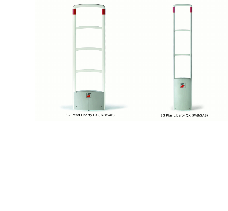
the PX/QX with Coupler (PAB/SAB) systems.
In this manual, most illustrations and pictures will show the PX as a place of reference, but it is to
be understood that each antenna would be installed in the same manner (unless otherwise noted).
Figure 1 PX and QX with Coupler Antennas

PX/QX with Coupler Installation Manual Version *61
C H A P T E R
2
INST AL L AT IO N O VERVIEW
Overview
This chapter is an overview of the installation process:
1. Requirements: Tool and part requirements for a typical installation.
2. Installation Outline: Lists the basic installation steps in sequence.
Requirements
Tools
The following tools are required for Liberty Antenna installations:
Arrow T-25 Staple Gun
Diagonal wire cutter
Hammer drill with 3/16” and 1/2” bits
Extension cord
Tape Measure
Hammer
Marker, Black Felt
Ratchet driver with 9/16” socket
Screwdrivers, mini, regular and #2 Phillips
Hacksaw
Utility knife
Wire Snake
Wire Strippers
Wrench, combination end 9/16”
PX/QX With Coupler Installation Manual (This manual)
Tuning Procedure, TR4024/26 Checkpoint 7255486
Checkpoint Systems Field Service Diagnostic Management Software (DMS version 1.5.8
or later version) installed on a laptop with the appropriate cables. DMS is an application

PX/QX with Coupler Installation Manual Version *61
developed to install and configure TR4024/26 boards via serial connections. DMS
provides for firmware updates without replacement of microchips.
Parts
Quantity will vary according to site.
18 AWG 2-conductor (STP)
CAT5e cable
22 AWG 4-conductor (STP) (5594)
1/2” Anchor Bolts
*DekDuct (wire chase)
*Wiremold (1500 or 2600 series)
*Wiremold anchor bolts Note:
*Wire routing methods will vary by installation.
Installation Outline
Follow this sequence to successfully install the components:
1. Determine optimal antenna placement based upon antenna type, tag type, and door
opening width. (Refer to the Liberty Product Reference Guide)
2. Determine power supply requirements and the ideal power supply location. (See
“Appendix 2 Power Supplies”)
3. Physically mount the antennas.
4. Connect the antenna wiring.
5. Install peripherals.
6. Configure the system using DMS.
The information covered in steps 1 and 2 is generally used during the survey and planning stage,
but it is important for the installer to keep these specifications in mind to ensure that the systems
are installed to specification.

PX/QX with Coupler Installation Manual Version *61
C H A P T E R
3
PHYSIC AL INST ALL AT ION
Overview
This chapter covers the physical placement and installation of the Liberty antennas and power
supply in the following sections:
1. Placement: How to determine the proper placement of the antennas.
2. Power Supply: Information on typical power supply placement.
3. Wire Routing: Information on typical wire routing methods.
4. Antenna Mounting: Antenna mounting information.
Placement
For the purposes of consistency, the measurements listed and shown in this chapter are baseline
measurements, based on the 410 series tag. If an installation must support other tag types, the on-
center distance between antennas may deviate from what is shown in this chapter. For detailed
information please refer to the Liberty Product Reference Guide•
To meet both CE and FCC requirements, all measurements will be listed in the following format:
Metric [Imperial] Example: 46cm [18in.]
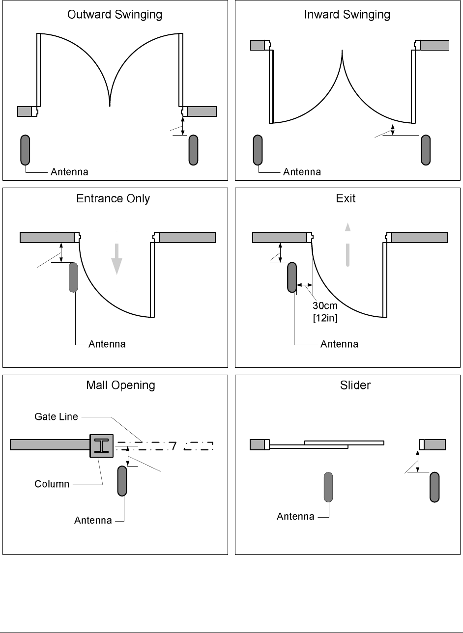
Distance from Door
Outward swinging (double & single): The minimum distance back from the door frame is
46cm[18in].
Inward Swinging (double): The minimum distance back from the edge of the fully open
door is 30cm[12in].
Mall Opening (No moving doors): The minimum distance back from the lease-line or
gate line is 30cm[12in].
Sliding: The minimum distance back from the door frame is 46cm[18in].
Single Inward Swinging (Entrance): The minimum distance back from the door frame (on
the latch side of the door) is 30cm[12in]. This configuration typically only requires a
single antenna on the latch side of the door. The inside edge of the antenna must be clear
of the inward swinging door.
Single Inward Swinging (Exit): Specifications are the same as the Single Inward
Swinging (Entrance), with the exception of: a) In order to meet ADA (Americans with
Disabilities Act) requirements in the UD the Antenna on the latch side of the door must
be a minimum of 30cm[12in] from the edge of the door opening.
PX/QX with Coupler Installation Manual Version *61
46cm
[18in]
30cm
[12in]
30cm
[12in]
30cm
[12in]
30cm
[12in]
46cm
[18in]
Figure 2 Recommended Antenna Placement
Please refer to the Figure 2 Recommended Antenna for proper antenna placement

PX/QX with Coupler Installation Manual Version *61
Aisle Width
The maximum aisle width for the PX/QX Liberty antennas (with 410 series tag) is:
PX with Coupler (PAB/SAB) – 1.8 m [6 ft]
QX with Coupler (PAB/SAB) – 1.2 m [4 ft]
System performance is affected by aisle width and tag type. For aisle width details please refer to
the Liberty Product Reference Guide
Power Supply
Both PX and QX with coupler antennas utilize a +24 VDC power supply.
Placement
The power supply can be placed near the system, under a cashwrap counter, under shelving, above
the drop ceiling (if using plenum-rated cabling), or in a nearby utility closet.
Placement Requirements:
The power supply must be within 18m [60ft] of the furthest antenna.
The power supply must be placed no higher than what is accessible from a store ladder.
If mounted in a plenum space, proper plenum rated wiring and plenum rated enclosures
are required.
Note: For more information about power supplies, please see “Power Supplies” on Appendix 2
Antenna Mounting
Antennas are typically not mounted until after the finished flooring is in place.
Mounting Hardware
For mounting on Concrete Floor
Utilize two (2) 1.3cm [.5in.] anchor bolts per antenna.
Figure 3 Anchor Bolt (Concrete Mounting)
Wood Floor
Utilize two (2) 1.3cm [.5in] lag bolts per antenna.
Figure 4 Lag Bolt (Wood Mounting)
PX/QX with Coupler Installation Manual Version *61
Wire Routing
Methods of Wire Routing
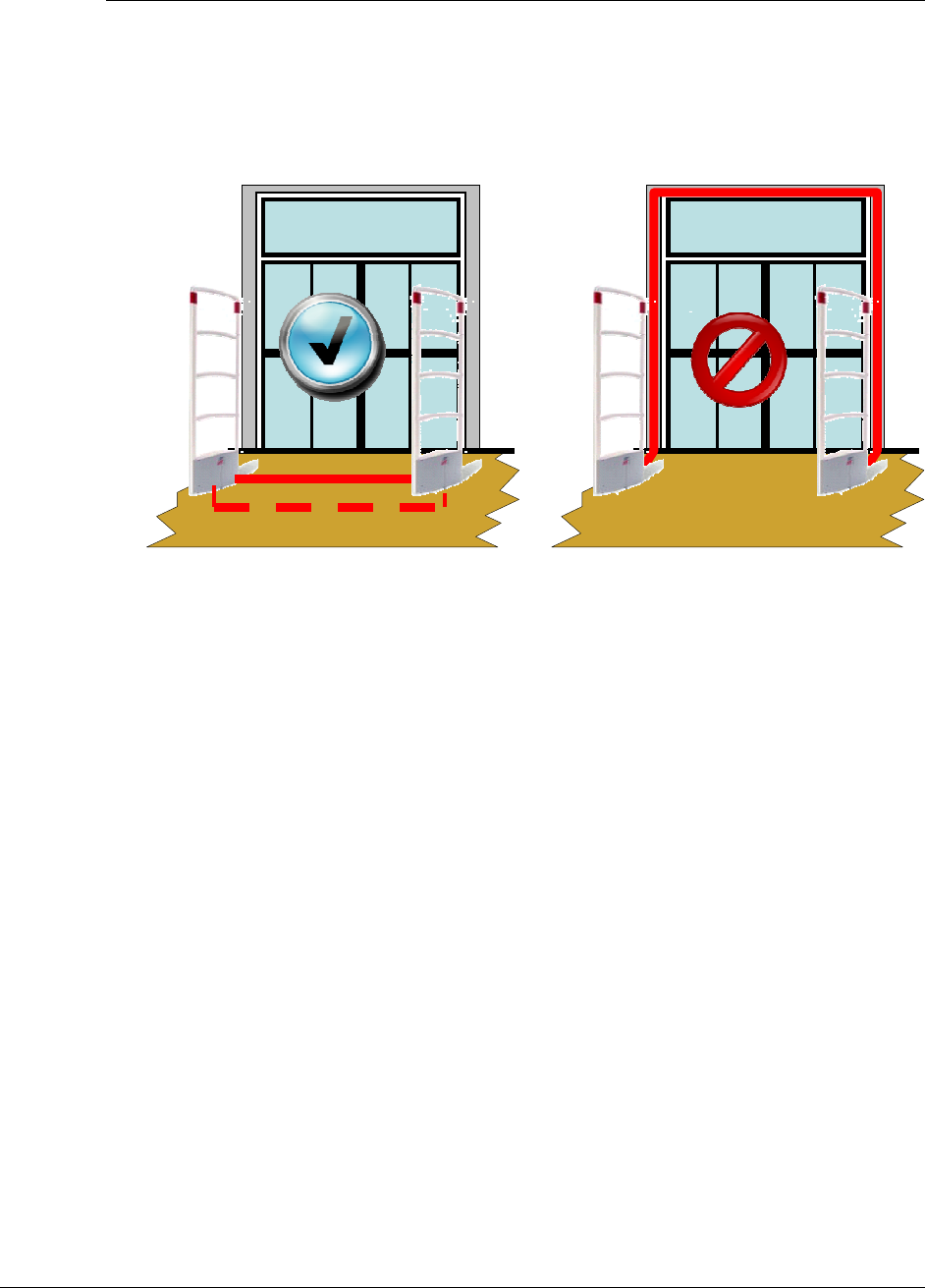
The cabling between PAB and SAB has to be routed either under floor or through floor wiremold.
“Up & Over” routing method is not permitted for cabling between PAB and SAB.
Figure 5 Methods of Wire Routing
Floor Trench: Typically 1.3cm [.5in.] wide by 3.8cm [1.5in.], but an increase in
dimensions is recommended for more than two antennas.
Wiremold: 1500 or 2600 series wire mold can be utilized. Typically wire mold is not
used within customer traffic areas, so a typical placement is from the outside of the
antennas to the doorframe.
Conduit: 2.5cm [1in.] diameter conduit can be utilized in new construction situations. It is
recommended that swept 90 degree angles are used, and that pull-strings are provided by
the conduit installer.
Wall / Mullion: Wires can be contained within mullions, and hollow walls for vertical
wire runs.
Dek-Duct / Panduit: Wires can be contained within surface mount Dek-Duct or Panduit
for vertical wire runs.
WARNING: Any wiring in plenum areas must be plenum rated. Additionally, ensure that the
wire is installed in accordance with applicable (local/national) electrical codes.
Correct Wire Routing
(A)
Incorrect Wire Routing
(B)
OR

PX/QX with Coupler Installation Manual Version *61
C H A P T E R
4
ANT ENN A WI RING
Overview
This chapter describes the PX/QX with Coupler primary (PAB) and secondary (SAB) antennas
wiring and cabling.
WARNING: This system runs on TR4026† electronics with firmware 46.0 or higher. It is critical
to note that ONLY TR4026 electronics can be used in conjunction with this system.
Information is covered in the following sections:
1. General wiring instruction
2. Single Aisle wiring
3. Multi Aisles wiring
General Wiring Instruction
This section describes how to prepare and wire all cables and wires involved in the antenna
installation. Wires can be cut to required length.
Wiring between PAB/SAB
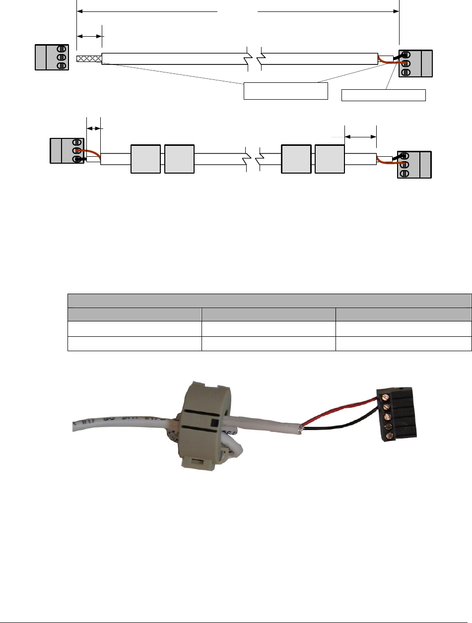
There are only two (2) wires connected between PAB and SAB. They are 1) RG59 coax cable and
2) SAB Light cable (22 AWG 4-conductor (STP) (5594))
RG59 Coax Cable:
A 3m[10ft] long, one end pre-terminated RG59 coaxial cable is packed with SAB antenna. It
connects the coupler boards (J5) in the primary antenna (PAB) and in the secondary antenna
(SAB). It is recommended to leave the pre-terminated end at the SAB. The installer has to
terminate the other end at the primary antenna.
1. Strip the coax cable jack off for about 19mm [3/4in] at the un-terminated end, as shown
in Figure 6 RG 59 Coax cable wiring diagram (A).
2. Separate and twist the shield braid tightly, leaving now loose strands.
3. Strip the center conductor to about 6 mm [1/4 in], insert it into connector pin #1, then
tighten it with screwdriver.
4. Insert the twisted shield braid to the connector pin #2, and secure it with screwdriver.
5. Clamp 2 ferrite cores on each ends (PAB and SAB).
† Modified TR4024 electronics may be used in the first few shipments.
PX/QX with Coupler Installation Manual Version *61
6. Figure 6 RG 59 Coax cable wiring diagram (B) shows the RG59 cable assembly been
completely terminated with ferrite cores clamped on both ends.
1
2
3
1
2
3
3
2
1
3m[10ft]
19mm[3/4in]
25mm[1 in]
12mm[1/2in]
(A)
(B)
Center Conductor
Shield Conductor
3
2
1
Figure 6 RG 59 Coax cable wiring diagram
SAB Light Cable
It is recommended to use CKP standard field service truck stock 4-conductor wire (AWG22). Red
wire connects LT+ terminal and black wire connects LT- terminal. The SAB light cable must
mount a cylindrical ferrite at each end in PAB and SAB. A ferrite core with three turns is attached
to each end.
SAB Light Cable Wiring Table
Wire Color Primary Antenna (PAB) Secondary Antenna (SAB)
RED J11-1 LT+
BLACK J11-2 LT-
Table 1 SAB Light Cable Wiring Table
Figure 7 SAB Light cable with ferrite core.
PX/QX with Coupler Installation Manual Version *61
Wiring between PABs
When multiple antenna aisles are installed, it may require installing sync wire and network
communication cable between the aisles. For PX/QX with Coupler installation, all sync cables and
network communication cables are connected to the TR4026 electronic boards in the primary
antennas (PABs).
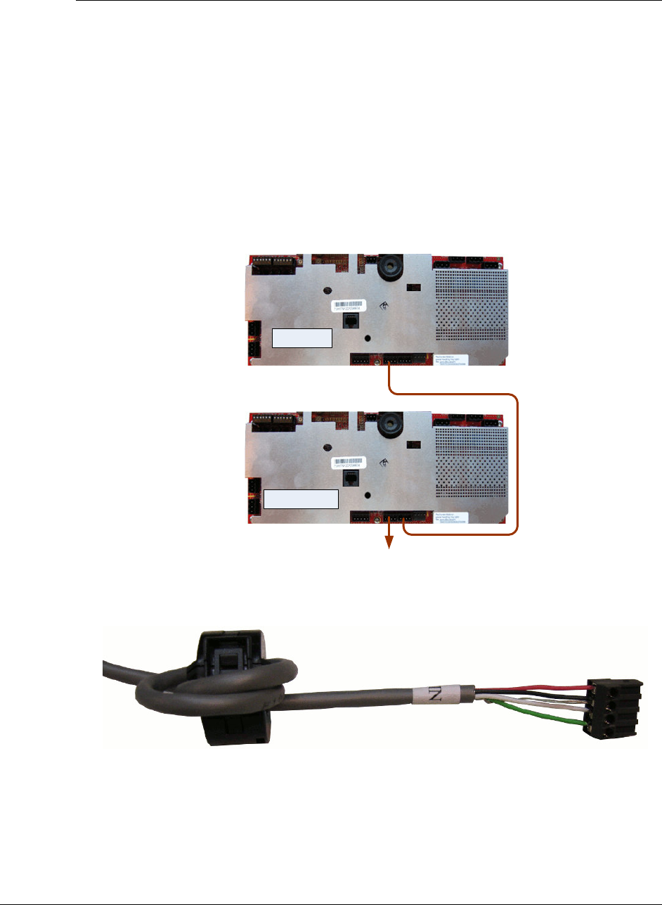
Sync Cable
The sync cable (RF Sync) needs to be installed between PABs if the distance between aisles is
under 40 feet. If two aisles are more than 40 feet apart, no sync cable is needed. Use 22 AWG
4-conductor (STP) (5594) cable for sync cable. Follow the Sync Cable Wiring Table below to
wire it to appropriate terminals. Sync cables are wired in daisy chain style. There are two sync
cables in a PAB antenna, the input cable and the output cable The first PAB only uses Sync
Output cable, the last PAB has the Input sync cable. The Output cable connects from terminal (J10)
to next PAB’s Sync Input terminal (J9). Figure 8 Wiring Sync Cable illustrates the wiring method.
Please refer the table below for Sync wire terminal connector pin assignment.
J10
J10
J9
J9
First PAB
Second PAB
To Third PAB
Figure 8 Wiring Sync Cable
Figure 9 Sync cable with ferrite core
Note: A ferrite core with three (3) turns is attached at each end.
PX/QX with Coupler Installation Manual Version *61
Sync Input (5594 4-conductor 22AWG wire)
Wire Color Description J9/J10
Green SYNC - 1
White SYNC + 2
Black & Drain GND 3
Red ALG 4
Table 2 Sync Cable Wiring Table
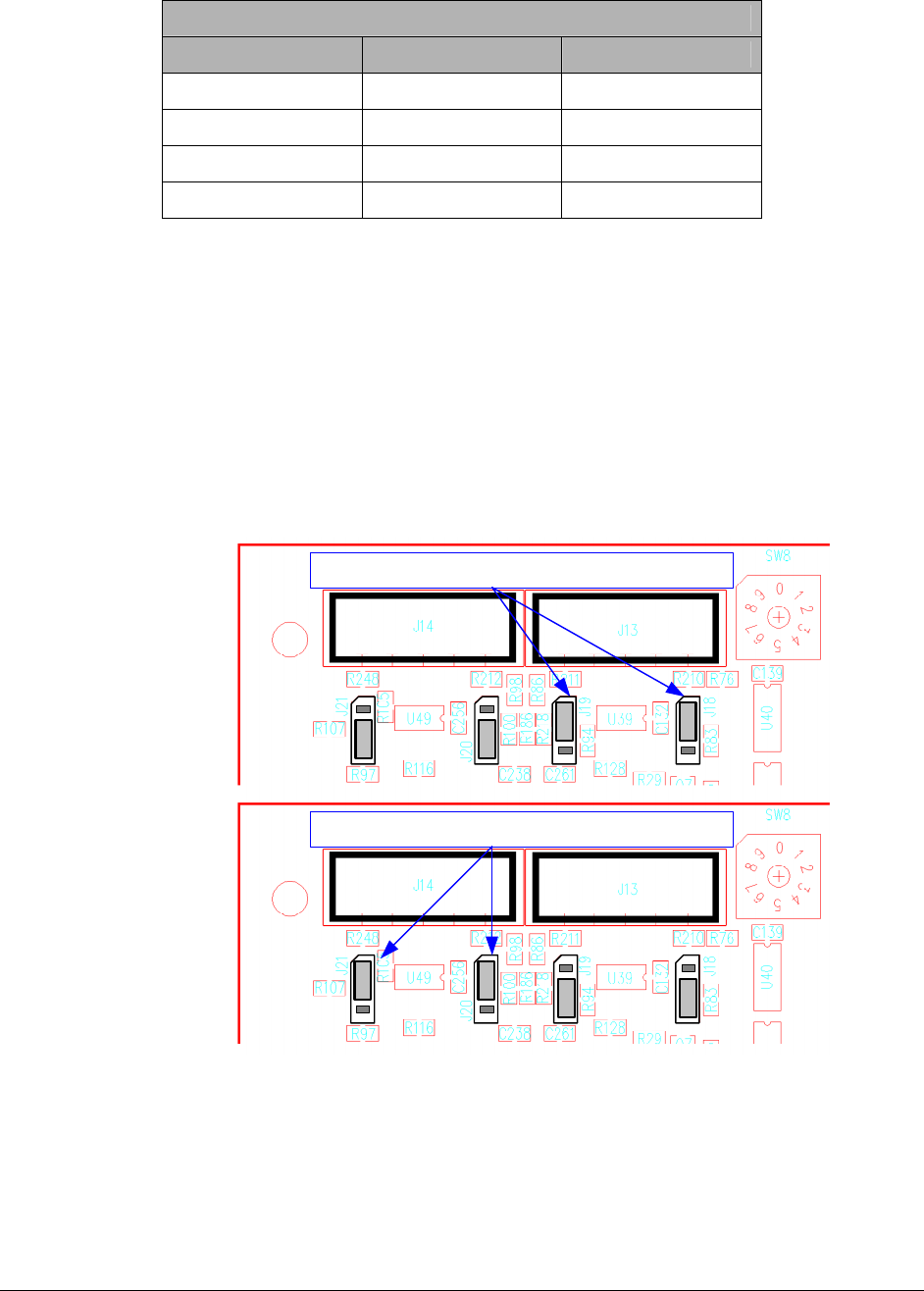
Communication Cable
It is also called inter-pedestal network cable. It enables communications between aisles. Similar to
the Sync wire, inter-pedestal communication network is wired as daisy chain. J14 and J13 are the
input and output terminals. The first PAB is only installed with Comm Out cable at terminal J13.
It connects to the second PAB’s input terminal J14. Then the second PAB’s J13 is connected to
the third PAB’s J14. The last PAB in the daisy chain only has the Comm In cable which is
connected to its J14 terminal. Unlike the sync cable wiring, the first PAB and last PAB in the
inter-pedestal network require additional termination jumper settings. Please refer to the Figure 10
Communication Termination Jumper Settings below for proper termination jumper settings.
J14 J13
Last PAB Termination Jumper Settings
J14 J13
First PAB Termination Jumper Settings
Figure 10 Communication Termination Jumper Settings
Follow the Communication Cable Wiring Table below to properly connect the communication
cables to the TR4026 electronics in the PABs. A ferrite core with three (3) turns is attached at each
end. CAT5E cable is recommended for wiring inter-pedestal network.
PX/QX with Coupler Installation Manual Version *61
Figure 11 Communication cable
COMM Cable (CAT5E)
Wire Color Description J13/J14
Blue DB- 1
White -Blue DB+ 2
Drain GND 3
NC GND 4
White-Orange CB+ 5
Orange CB- 6
Table 3 Communication Cable Wiring Table
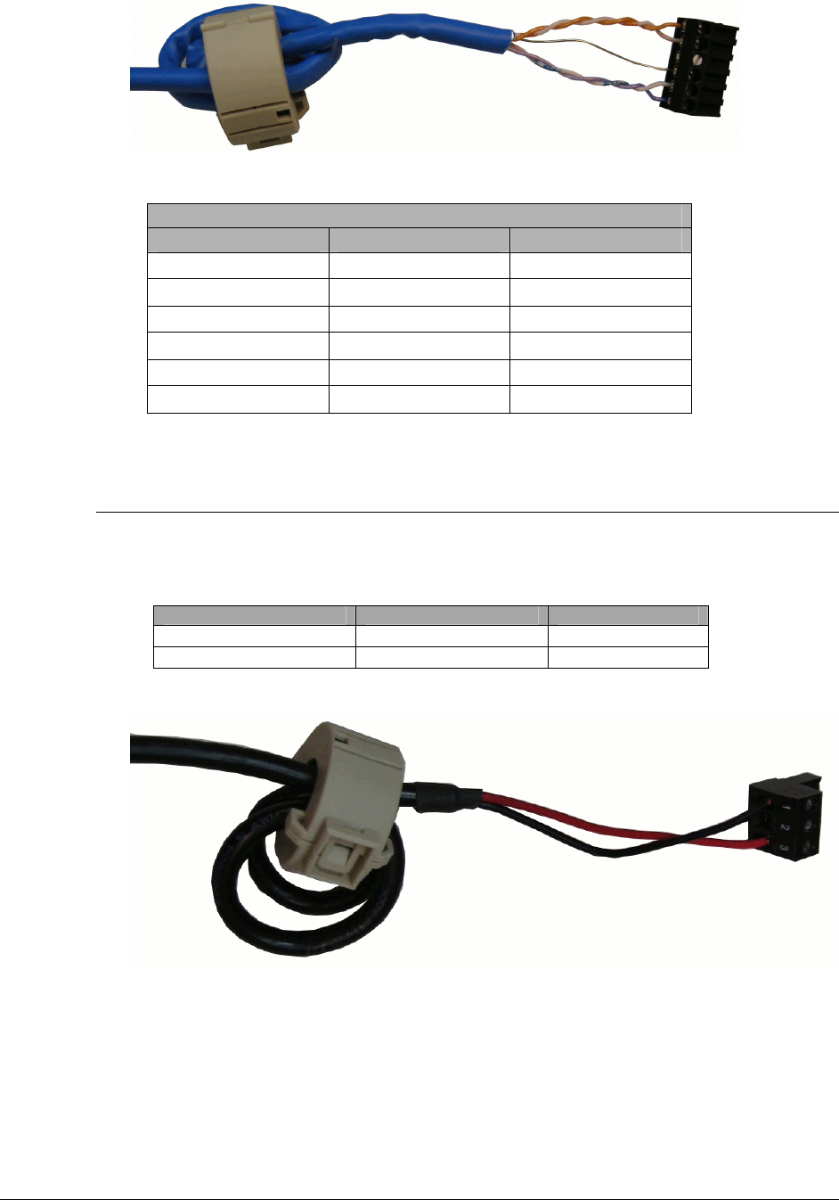
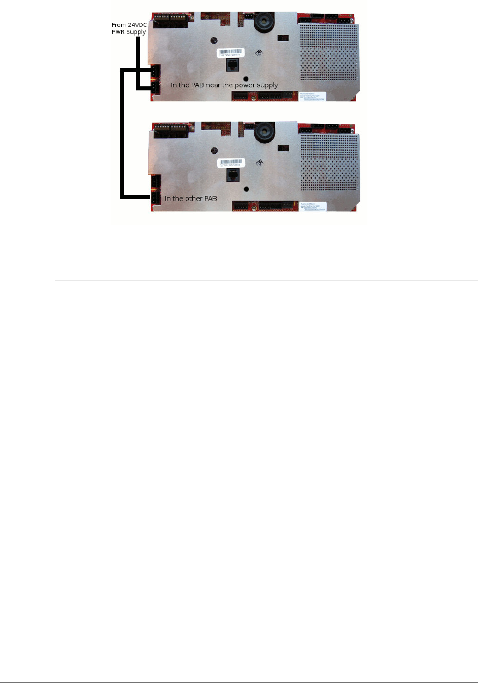
Wiring 24VDC power supply
A Checkpoint certified 24VDC power supply can power up to two (2) PABs. It is recommended to
wire the 24VDC power suppler to the nearer PAB (J8), then, connect wire from this PAB’s J12
connector to the J8 connector in the other PAB (J8). (See Figure 13 24 VDC power supply wiring
method). 24VDC power cable uses AWG18 two (2) conductor cable.
Connect Pin # Wire Color Description
1 Black GND
3 Red +24 V
Table 4 Power Cable Wiring Table
Figure 12 24 VDC Power Supply Cable
PX/QX with Coupler Installation Manual Version *61
Figure 13 24 VDC power supply wiring method
Wiring peripherals
Follow the appropriate installation manual for wiring peripheral devices.
PX/QX with Coupler Installation Manual Version *61
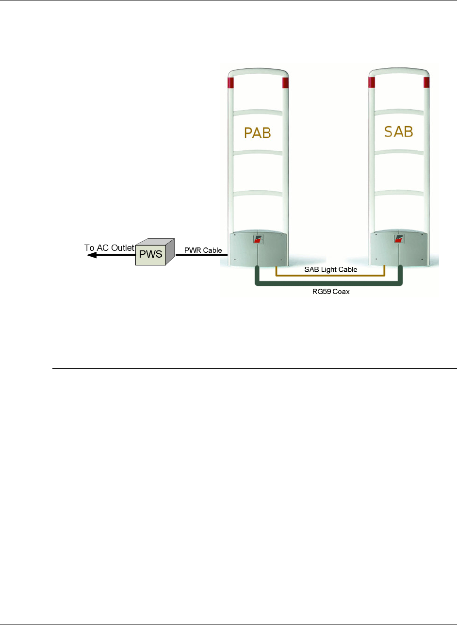
Single Aisle Wiring
The single aisle installation is the most common PX/QX with Coupler application which best
utilizes the PAB-SAB configuration (see Figure 14 Single Aisle). A typical single aisle installation
consists of a PX (QX) primary antenna (PAB), a secondary antenna (SAB), a power supply and a
cable kit (packaged with secondary antenna). It is recommended to start SAB wiring first, then
wire the PAB. Connect the power cable last.
Figure 14 Single Aisle
Secondary antenna (SAB) wiring
Step 1: Open the base cover.
Step 2: Plug the pre-terminated RG59 coax cable onto coupler board J5, then mount two (2)
ferrite clippers close to the connector (see Figure 6 RG 59 Coax cable wiring diagram).
Note: It is recommended to leave the pre-terminated coax cable end at SAB location where the
cable was laid out.
Step 3: Connect the SAB Light cable to the wire terminal LT+ (RED) / LT- (Black).
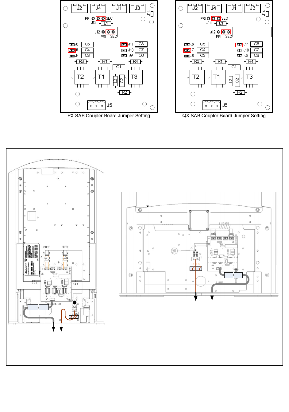
Step 4: Inspect wiring and connections, confirm coupler board jumper settings (see Figure 15
SAB Coupler Board Jumper Settings).
Step 5: Put the base cover back and secure.
PX/QX with Coupler Installation Manual Version *61
Figure 15 SAB Coupler Board Jumper Settings
3G Plus Liberty QX - SAB 3G Trend Liberty PX - SAB
RG59 To PAB Coupler
SAB Light- To PAB J11
RG59 To PAB Coupler
SAB Light- To PAB J11
Figure 16 SAB Antenna Wiring
PX/QX with Coupler Installation Manual Version *61
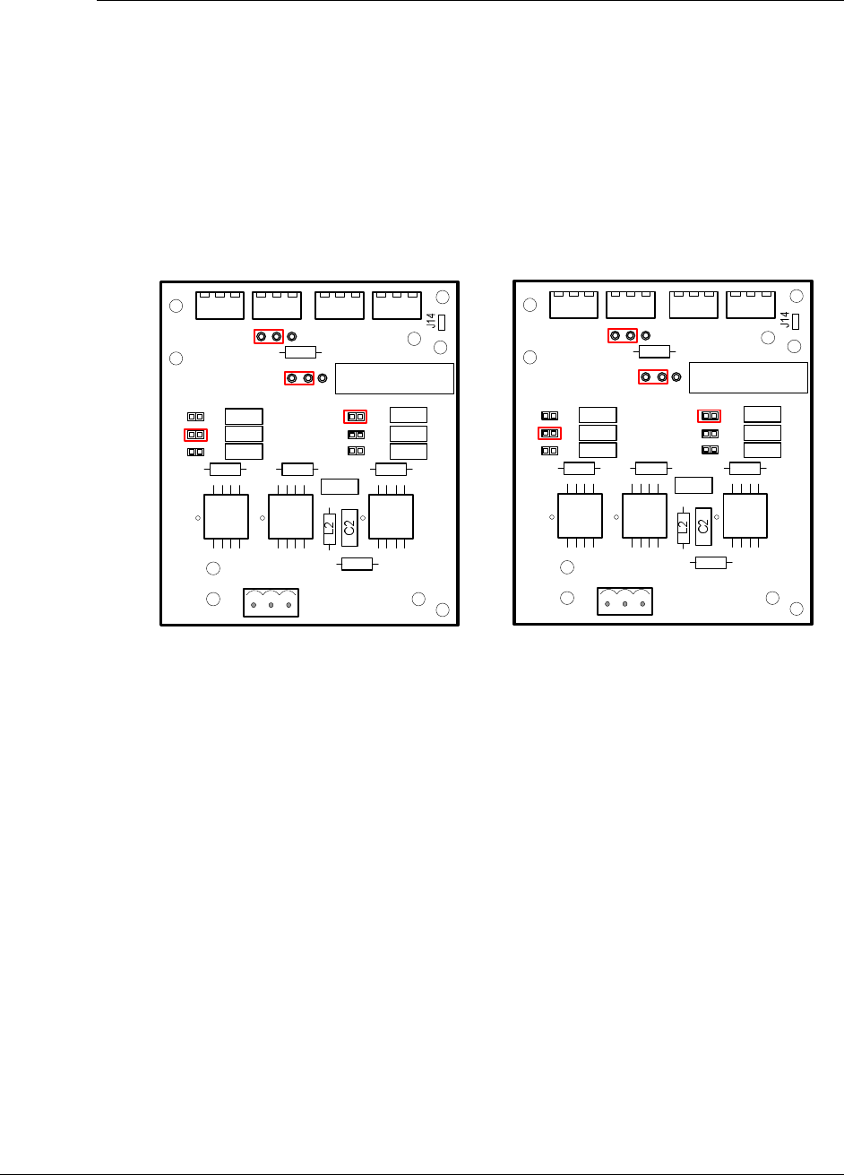
Primary antenna (PAB) wiring
Step 1: Open the base cover(s).
Step 2: Cut, strip and terminate the RG59 coax cable, then plug it to the coupler board. Check the
coupler board jumper settings (see Figure 17 PAB Coupler Board Jumper Settings).
Step 3: Connect the SAB Light Cable wires to the J11 on the electronic reader board (TR4026).
Step 4: Connect network and peripheral cables (see next Chapter, Network and Peripheral
Wiring), if required.
Step 5: Connect 24v DC power cable to J8 on the electronic reader board (TR4026).
Step 6: Inspect wiring and connections, confirm coupler board jumper settings (see Figure 17
PAB Coupler Board Jumper Settings).
Step 7: Put the base cover(s) back and secure.
T2 T1 T3
J2 J4 J1 J3
C7
C6C3
C4
C5 C8
C1
R2
R1R3 R4
L1
J11
J10
J9
PRI
PRI SEC
SEC
J6
J7
J8
J5
J12
J13
T2 T1 T3
J2 J4 J1 J3
C7
C6C3
C4
C5 C8
C1
R2
R1R3 R4
L1
J11
J10
J9
PRI
PRI SEC
SEC
J6
J7
J8
J5
J12
J13
PX PAB Coupler Board Jumper Setting QX PAB Coupler Board Jumper Setting
Figure 17 PAB Coupler Board Jumper Settings
PX/QX with Coupler Installation Manual Version *61
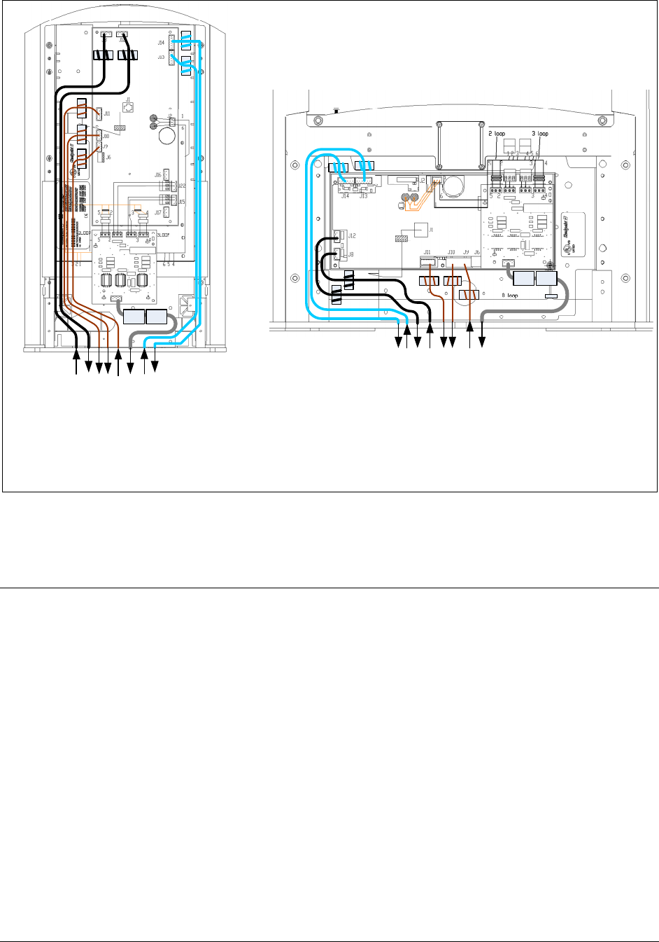
From 24VDC Pwr Supply
To SAB Coupler
Sync Input
Sync Output
To SAB Light
From 24VDC Pwr Supply
Supply 2nd PAB 24VDC
Comm In
Comm Out
To SAB Coupler
Sync Input
Sync Output
To SAB Light
Supply 2nd PAB 24VDC
Comm In
Comm Out
3G Plus Liberty QX - PAB 3G Trend Liberty PX - PAB
Figure 18 PAB Antenna Wiring
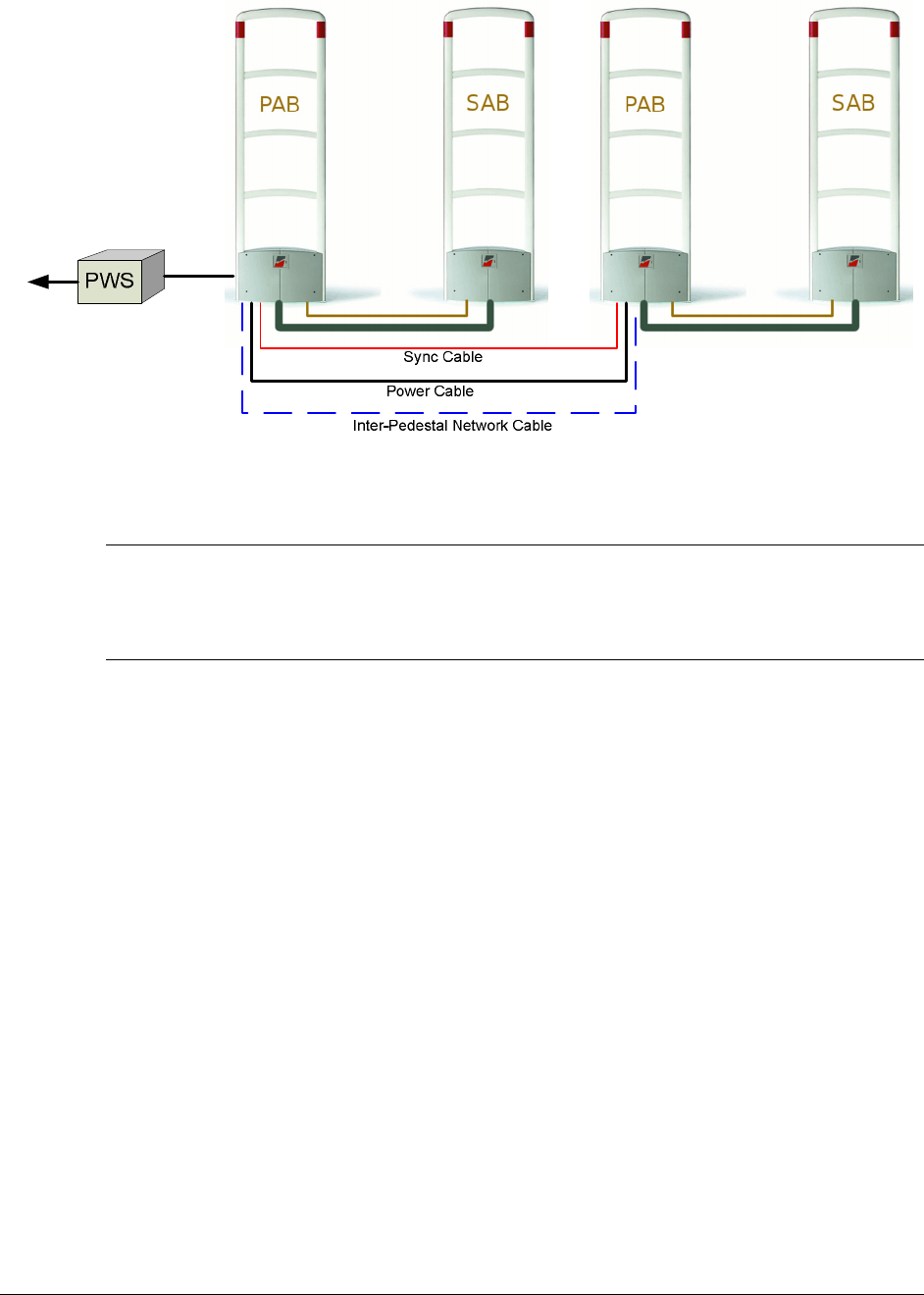
Multi-Aisle Wiring
A Multi-Aisle installation is when there are more than one antenna pairs installed at an
entrance/exit location. Multi-Aisle installation consist two (2) or more primary antennas (PAB). If
the distance between two (2) aisles is shorter or equal to 40 feet, sync cable(s) is needed to connect
PABs’ RF sync terminals. In addition, a 24VDC power supply can drive 2 aisles (except
Celetronix LFVC36FS24S91). In some applications, inter-pedestal network is required for
multiple aisle installation. Both 3G Trend/Liberty PX and 3G Plus/Liberty QX offer the capability
of inter-pedestal communication network via PAB’s communication ports. Figure 19 Multiple
Aisle shows a typical two (2) aisle configuration.
PX/QX with Coupler Installation Manual Version *61
Figure 19 Multiple Aisles
Secondary antenna (SAB) wiring
Follow the same steps as they are described in Single-Aisle Wiring SAB section.
Primary antenna (PAB) wiring
Step 1 to Step 5 are the same as they are described in Single-Aisle PAB wiring section.
Step 6: Connect the sync cable to J 10 and J9 on the electronic reader board (TR4026).
Step 7: Connect 24v DC power cable to J8 on the electronic reader board (TR4026). Connect
another 24VDC power cable to J12 if there is a PAB powered via this PAB.
Step 8: Inspect wiring and connections, confirm coupler board jumper settings (see Figure 17
PAB Coupler Board Jumper Settings).
Step 9: Put the base cover(s) back and secure.

PX/QX with Coupler Installation Manual Version *61
C H A P T E R
5
NETW O RKING AND PERIPHER AL S
Overview
This chapter describes the PX/QX with Coupler antennas network wiring and peripheral device
wiring.
Note: all network wires and peripheral device wires go to primary antenna only.
Inter-pedestal Networking
Both PX and QX with Coupler systems offer inter-pedestal networking via inter-pedestal
communication network. Please refer to the previous chapter for inter-pedestal communication
network wiring. Use DMS tool to configure and setup inter-pedestal network (will described in
next chapter)
Peripherals
Both PX and QX with Coupler systems support following peripheral devices:
Voice Alarm
Metal Detection
Modem
CheckPro Manager Unit
Wifi (Only 3G Trend/Liberty PX supports this peripheral device)
Please refer the peripheral device’s installation manuals for proper installation and wiring
PX/QX with Coupler Installation Manual Version *61
C H A P T E R
6
SYST EM CONF IGUR AT IO N VI A DM S
Overview
This chapter reviews how to configure 3G Trend/Liberty PX and 3G Plus/Liberty QX PAB/SAB
system using DMS. Antenna tuning including coupler jumper setting are covered in a separate
document “3G Trend/Liberty PX and 3G Plus/Liberty QX PAB/SAB Tuning Guide”. Please
follow this tuning guide to optimize the system performance after completing the system
configuration.
Note: Please use DMS version 1.5.8 and later. TR4026 firmware version must be V46.00 and
later.
System Setup Using DMS
PX/QX with Coupler systems run with firmware version 46 and later. It requires DMS tool
version 1.5.8 and later version.
Single-Aisle setup
The Single Aisle Setup process consists of following steps:
1. Make a new DMS connection – for new installation
2. Setup the aisle as PAB/SAB (coupler) operation mode
3. Antenna Tuning
Make a New DMS Connection
1. Connect the service PC laptop to a TR4026 board in a PAB
2. Launch the DMS program (version 1.5.8 and later)
Note: Please refer DMS User’s Guide for help in using DMS tool.
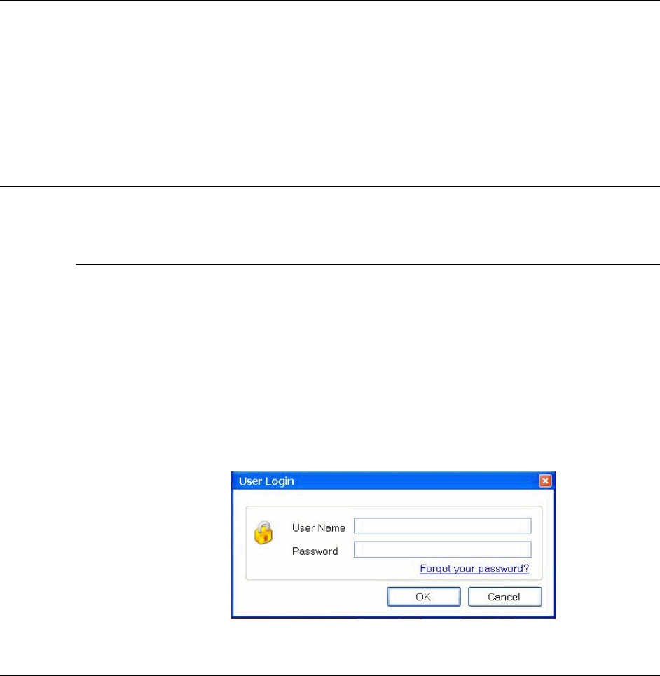
Figure 20 Login DMS
PX/QX with Coupler Installation Manual Version *61
3. A login window will show up. Type in your user name and password. Then click OK to
login DMS
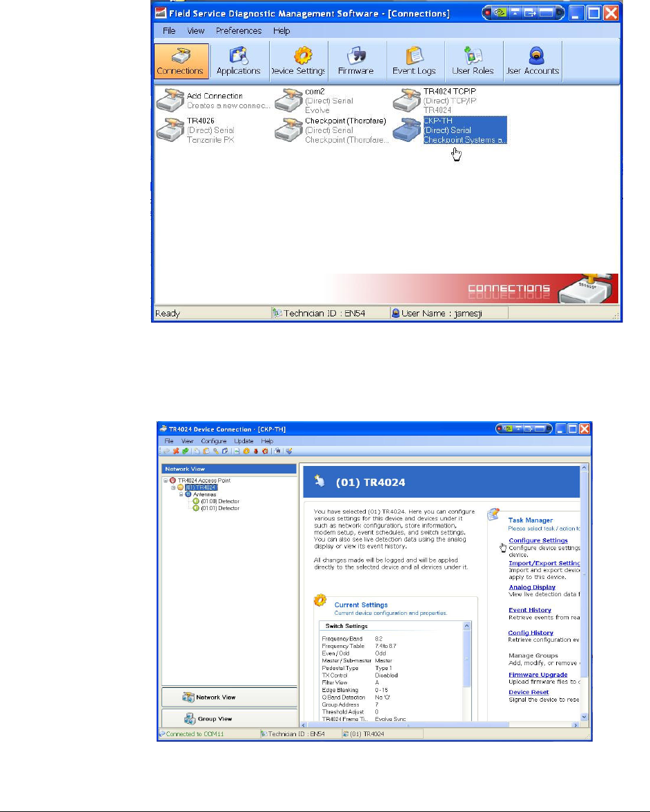
4. DMS will bring up and connections windows as shown as in Figure 21 Add a Connection.
Then double click the icon named “ Add Connection Creates a new connection”
Figure 21 Add a Connection
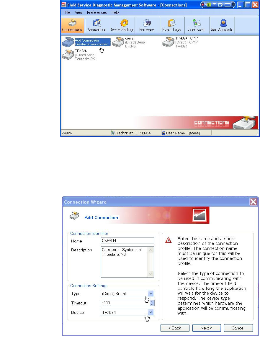
5. A “Connection Wizard” program will start. Click Next, and proceed to the “Add
Connection” window.
6. In the “Add Connection” window, enter the name and description in the “Connection
Identifier section. In the “Connection Setting” section, make selection at “Type” and
“Device” selection boxes. Shown in Figure 22 New Connection Setup
Figure 22 New Connection Setup
PX/QX with Coupler Installation Manual Version *61
7. Click Next, a serial port selection window shows up, select a proper COM port on your
laptop which the TR4024 is connected; then click Next. The final connection summary
window comes up, click Finish to complete the new connection setup.
8. Now the “Add a new connection” step is complete. The new connection icon “CKP-TH”
appears in the DMS connection window as shown in the figure below.
Figure 23 A New Connection Added
Setup the aisle as PAB/SAB (coupler) operation mode
1. Double click the newly added connection icon in the DMS connection window (e.g.
CKP-TH), a device connection window comes up. In the network view, you can expand
all device levels shown as in the figure below. Then select the aisle TR4024/26.
Figure 24 DMS Network View
PX/QX with Coupler Installation Manual Version *61
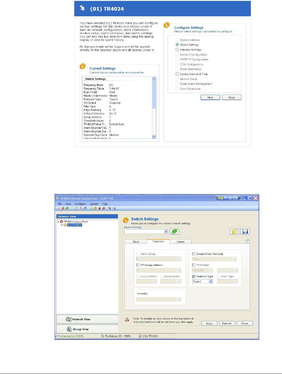
2. Click the Configure Settings from the Task manager on the right side
3. A configuration window comes up, select Switch Settings and then click Next.
Figure 25 Switch Setting
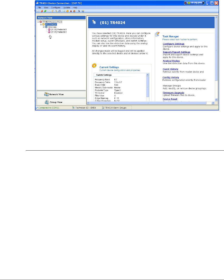
4. Select “Detection” tab. Check the “Pedestal Type” box, select “Type 2”, as shown in
figure below.
Note: Type 2 represents PX/QX with Coupler PAB/SAB operation mode.
Figure 26 Select Type 2
PX/QX with Coupler Installation Manual Version *61
5. Click Apply to complete the setup. A “Switch settings successfully set” message box will
come up. Click OK and Close.
6. Go back to the “Network View” window, and expand the network device level. The
device names under Antenna have been changed. Shown in Figure 27 Single Aisle Setup
Completion. This confirms the success for setting the PX/QX with Coupler operation
mode.
Figure 27 Single Aisle Setup Completion
Antenna Tuning
Please follow a separate document “PX/QX with Coupler Tuning Guide to complete this task.
Multi-Aisle Setup
The difference between a multiple aisles system and a single aisle system is that there is a master
aisle in the multiple aisles system, and the rest aisles are the sub master systems. Therefore, in
addition to setup the PAB/SAB (coupler), it needs to setup the master/submaster configuration.
Therefore the steps involved in a multiple aisles system are:
1. Make a new DMS connection – for new installation
2. Setup the aisles as PAB/SAB (coupler) operation mode
3. Setup Master and Sub Master aisles
4. Antenna Tuning
Step 1, 2 and 4 are the same process as described in Single Aisle Setup.
Step 3 Setup Master and Sub Master aisle.
There only one master antenna in a multi-aisle system. Remaining pedestals are set to submasters.
1. Select the master antenna from the network view
2. Click Configure Settings on the right side.
3. Select Switch Settings from the Configure Settings window, then, click Next.
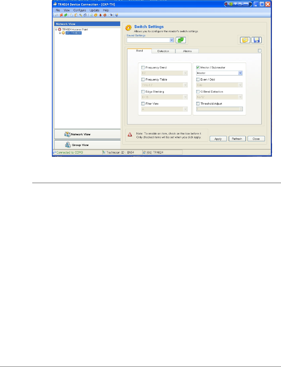
4. Click the “Band” tab, and select the Master from the Master/Submaster selection box.
5. Click Apply. A success setting message box will come up. Click OK. Then, click Close
to return to network view.
PX/QX with Coupler Installation Manual Version *61
6. Select the next antenna from the network view
7. Repeat step 2 and 3,
8. Click the “Band” tab, and select the SubMaster form the Master/Submaster selection box,
9. Click Apply, Same as step 5.
10. Repeat step 6 to 9 for rest PAB antennas in the network view.
Figure 28 Master/SubMaster Selection
Antenna Tuning
Please follow the PX/QX with Coupler Tuning Guide to perform the procedures.
PX/QX with Coupler Installation Manual Version *61
A P P E N D I X
1
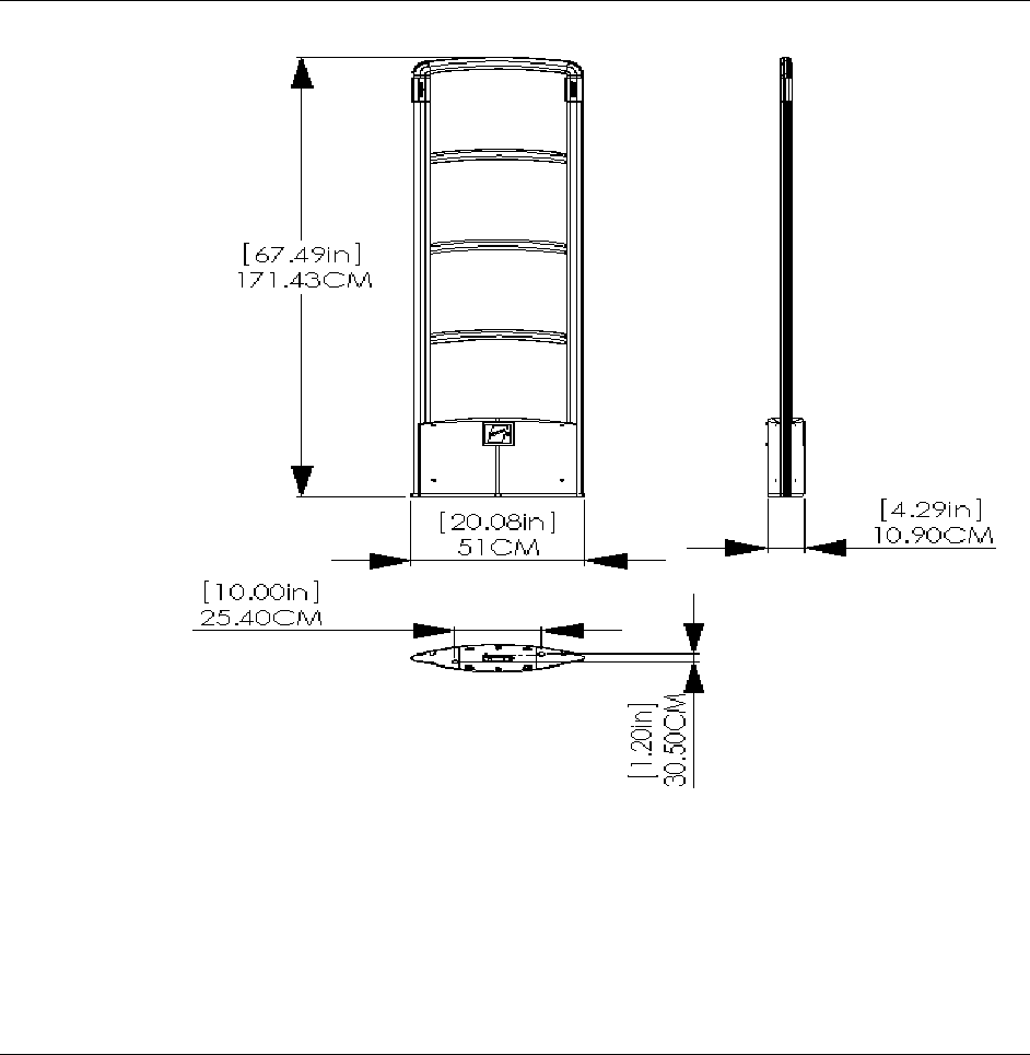
ANT ENN A DIM ENSIONS
3G Trend/Liberty PX
PX/QX with Coupler Installation Manual Version *61
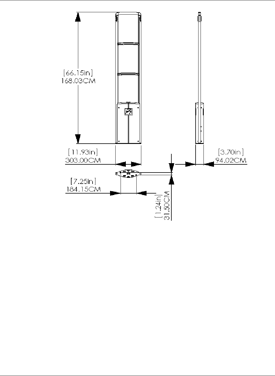
3G Plus/Liberty QX

PX/QX with Coupler Installation Manual Version *61
A P P E N D I X
2
POW ER SUPPL IES
Overview
This appendix covers all available (US and EU) 3G Trend/Liberty PX and 3G Plus/Liberty QX
compatible power supplies.
Details
Power supplies have an output of +24 VDC.
Requirements
In the US, if the power supply is to be installed in a plenum (HVAC ventilation) area, the Globtek
GS-599ES(R) and the Globtek GS-599MC-KIT(R) must be installed.
Capacity
The following power supplies can provide power for up to two aisle systems:
Globtek GS-599 UF
Globtek GS-599ES(R)
Celetron LFZVC65SG24E
The following power supply can provide power for one aisle systems:
Celetronix LFVC36FS24S91
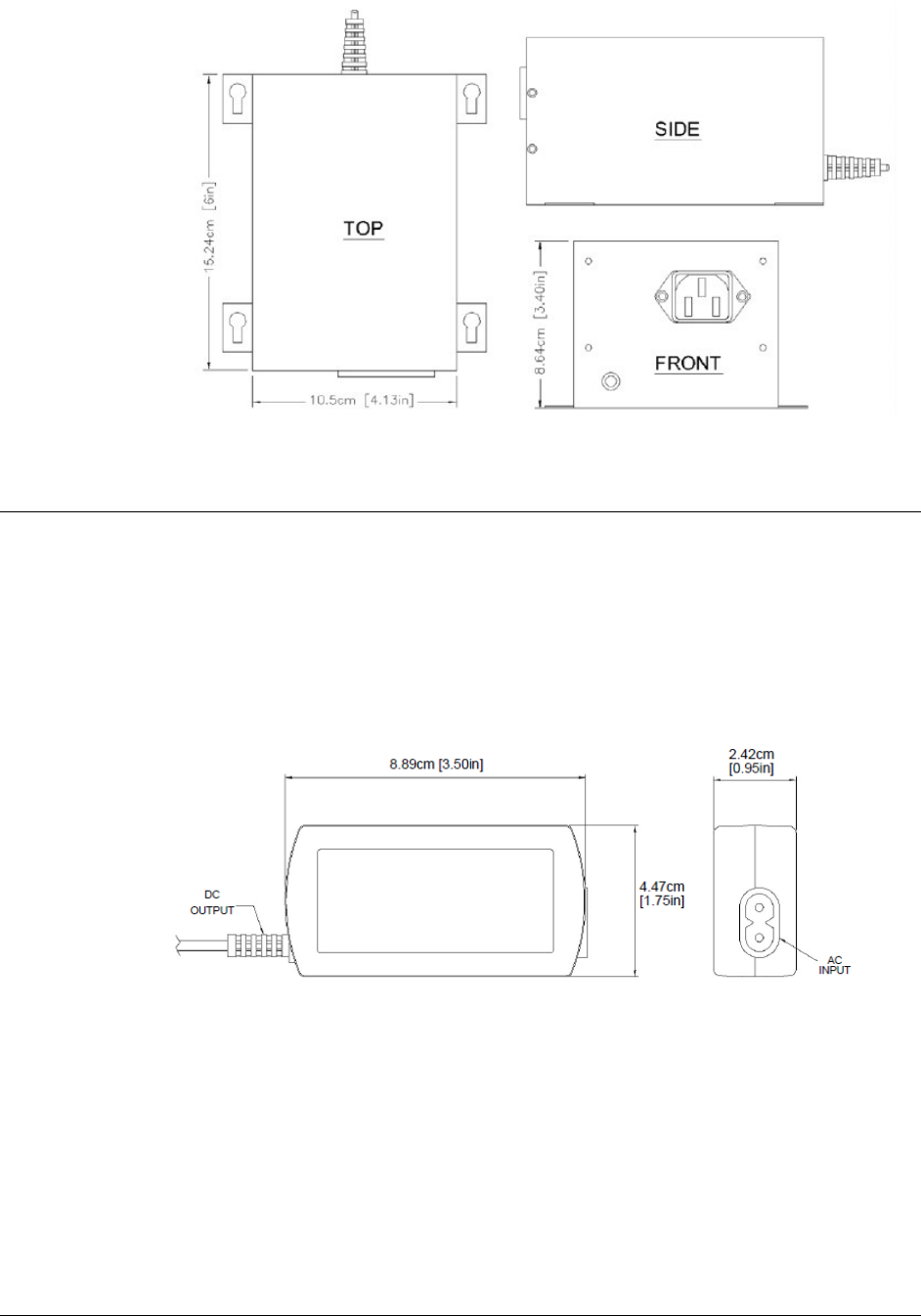
Power Supply Used in United States
Model
The US market uses one power supply types:
Globtek GS-599ES(R) (PN: 7116509)
Standard power supply rated for use in plenum areas.
Note: For use in plenum areas, the Globtek GS-599MC-KIT(R) must be used in conjunction
with the Globtek GS-599ES(R).
Dimensions
Width: 10.50cm [4.13in]
Length: 15.24cm [6.00in]
Height: 8.64cm [3.40in]
PX/QX with Coupler Installation Manual Version *61
Power Supply Used In Europe
Model
The EU market uses one power supply types:
Celetronix LFVC36FS24S91 (PN: 7683707)
Dimensions
Length: 8.89cm [3.50in]
Width: 2.42cm [0.95in]
Height: 4.47cm [1.75in]