Checkpoint Systems LIB24TZ Part 15 Anti-Pilferage Device User Manual Confidential Installation Manual rev
Checkpoint Systems Inc Part 15 Anti-Pilferage Device Confidential Installation Manual rev
Contents
- 1. Confidential_Installation Manual_rev
- 2. Manual
Confidential_Installation Manual_rev

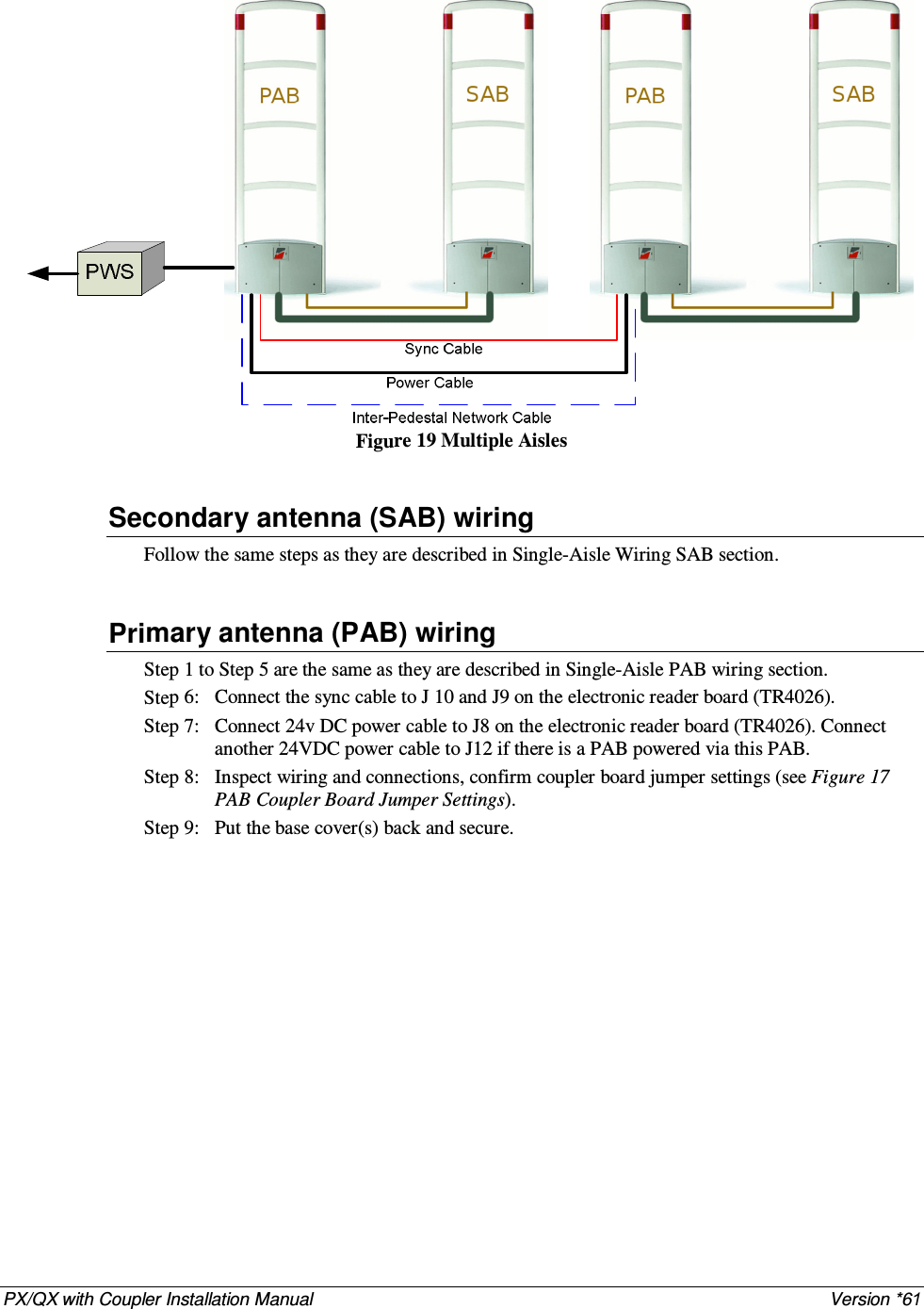
![PX/QX with Coupler Installation Manual Version *61 C H A P T E R 3 PHYSIC AL INST ALL AT ION Overview This chapter covers the physical placement and installation of the Liberty antennas and power supply in the following sections: 1. Placement: How to determine the proper placement of the antennas. 2. Power Supply: Information on typical power supply placement. 3. Wire Routing: Information on typical wire routing methods. 4. Antenna Mounting: Antenna mounting information. Placement For the purposes of consistency, the measurements listed and shown in this chapter are baseline measurements, based on the 410 series tag. If an installation must support other tag types, the on-center distance between antennas may deviate from what is shown in this chapter. For detailed information please refer to the Liberty Product Reference Guide• To meet both CE and FCC requirements, all measurements will be listed in the following format: Metric [Imperial] Example: 46cm [18in.] Distance from Door Outward swinging (double & single): The minimum distance back from the door frame is 46cm[18in]. Inward Swinging (double): The minimum distance back from the edge of the fully open door is 30cm[12in]. Mall Opening (No moving doors): The minimum distance back from the lease-line or gate line is 30cm[12in]. Sliding: The minimum distance back from the door frame is 46cm[18in]. Single Inward Swinging (Entrance): The minimum distance back from the door frame (on the latch side of the door) is 30cm[12in]. This configuration typically only requires a single antenna on the latch side of the door. The inside edge of the antenna must be clear of the inward swinging door. Single Inward Swinging (Exit): Specifications are the same as the Single Inward Swinging (Entrance), with the exception of: a) In order to meet ADA (Americans with Disabilities Act) requirements in the UD the Antenna on the latch side of the door must be a minimum of 30cm[12in] from the edge of the door opening.](https://usermanual.wiki/Checkpoint-Systems/LIB24TZ.Confidential-Installation-Manual-rev/User-Guide-1203977-Page-10.png)
![PX/QX with Coupler Installation Manual Version *61 46cm[18in]30cm[12in]30cm[12in]30cm[12in]30cm[12in]46cm[18in] Figure 2 Recommended Antenna Placement Please refer to the Figure 2 Recommended Antenna for proper antenna placement](https://usermanual.wiki/Checkpoint-Systems/LIB24TZ.Confidential-Installation-Manual-rev/User-Guide-1203977-Page-11.png)
![PX/QX with Coupler Installation Manual Version *61 Aisle Width The maximum aisle width for the PX/QX Liberty antennas (with 410 series tag) is: PX with Coupler (PAB/SAB) – 1.8 m [6 ft] QX with Coupler (PAB/SAB) – 1.2 m [4 ft] System performance is affected by aisle width and tag type. For aisle width details please refer to the Liberty Product Reference Guide Power Supply Both PX and QX with coupler antennas utilize a +24 VDC power supply. Placement The power supply can be placed near the system, under a cashwrap counter, under shelving, above the drop ceiling (if using plenum-rated cabling), or in a nearby utility closet. Placement Requirements: The power supply must be within 18m [60ft] of the furthest antenna. The power supply must be placed no higher than what is accessible from a store ladder. If mounted in a plenum space, proper plenum rated wiring and plenum rated enclosures are required. Note: For more information about power supplies, please see “Power Supplies” on Appendix 2 Antenna Mounting Antennas are typically not mounted until after the finished flooring is in place. Mounting Hardware For mounting on Concrete Floor Utilize two (2) 1.3cm [.5in.] anchor bolts per antenna. Figure 3 Anchor Bolt (Concrete Mounting) Wood Floor Utilize two (2) 1.3cm [.5in] lag bolts per antenna. Figure 4 Lag Bolt (Wood Mounting)](https://usermanual.wiki/Checkpoint-Systems/LIB24TZ.Confidential-Installation-Manual-rev/User-Guide-1203977-Page-12.png)
![PX/QX with Coupler Installation Manual Version *61 Wire Routing Methods of Wire Routing The cabling between PAB and SAB has to be routed either under floor or through floor wiremold. “Up & Over” routing method is not permitted for cabling between PAB and SAB. Figure 5 Methods of Wire Routing Floor Trench: Typically 1.3cm [.5in.] wide by 3.8cm [1.5in.], but an increase in dimensions is recommended for more than two antennas. Wiremold: 1500 or 2600 series wire mold can be utilized. Typically wire mold is not used within customer traffic areas, so a typical placement is from the outside of the antennas to the doorframe. Conduit: 2.5cm [1in.] diameter conduit can be utilized in new construction situations. It is recommended that swept 90 degree angles are used, and that pull-strings are provided by the conduit installer. Wall / Mullion: Wires can be contained within mullions, and hollow walls for vertical wire runs. Dek-Duct / Panduit: Wires can be contained within surface mount Dek-Duct or Panduit for vertical wire runs. WARNING: Any wiring in plenum areas must be plenum rated. Additionally, ensure that the wire is installed in accordance with applicable (local/national) electrical codes. Correct Wire Routing (A) Incorrect Wire Routing (B) OR](https://usermanual.wiki/Checkpoint-Systems/LIB24TZ.Confidential-Installation-Manual-rev/User-Guide-1203977-Page-13.png)
![PX/QX with Coupler Installation Manual Version *61 C H A P T E R 4 ANT ENN A WI RING Overview This chapter describes the PX/QX with Coupler primary (PAB) and secondary (SAB) antennas wiring and cabling. WARNING: This system runs on TR4026† electronics with firmware 46.0 or higher. It is critical to note that ONLY TR4026 electronics can be used in conjunction with this system. Information is covered in the following sections: 1. General wiring instruction 2. Single Aisle wiring 3. Multi Aisles wiring General Wiring Instruction This section describes how to prepare and wire all cables and wires involved in the antenna installation. Wires can be cut to required length. Wiring between PAB/SAB There are only two (2) wires connected between PAB and SAB. They are 1) RG59 coax cable and 2) SAB Light cable (22 AWG 4-conductor (STP) (5594)) RG59 Coax Cable: A 3m[10ft] long, one end pre-terminated RG59 coaxial cable is packed with SAB antenna. It connects the coupler boards (J5) in the primary antenna (PAB) and in the secondary antenna (SAB). It is recommended to leave the pre-terminated end at the SAB. The installer has to terminate the other end at the primary antenna. 1. Strip the coax cable jack off for about 19mm [3/4in] at the un-terminated end, as shown in Figure 6 RG 59 Coax cable wiring diagram (A). 2. Separate and twist the shield braid tightly, leaving now loose strands. 3. Strip the center conductor to about 6 mm [1/4 in], insert it into connector pin #1, then tighten it with screwdriver. 4. Insert the twisted shield braid to the connector pin #2, and secure it with screwdriver. 5. Clamp 2 ferrite cores on each ends (PAB and SAB). † Modified TR4024 electronics may be used in the first few shipments.](https://usermanual.wiki/Checkpoint-Systems/LIB24TZ.Confidential-Installation-Manual-rev/User-Guide-1203977-Page-14.png)
![PX/QX with Coupler Installation Manual Version *61 6. Figure 6 RG 59 Coax cable wiring diagram (B) shows the RG59 cable assembly been completely terminated with ferrite cores clamped on both ends. 1231233213m[10ft]19mm[3/4in]25mm[1 in]12mm[1/2in](A)(B)Center ConductorShield Conductor321 Figure 6 RG 59 Coax cable wiring diagram SAB Light Cable It is recommended to use CKP standard field service truck stock 4-conductor wire (AWG22). Red wire connects LT+ terminal and black wire connects LT- terminal. The SAB light cable must mount a cylindrical ferrite at each end in PAB and SAB. A ferrite core with three turns is attached to each end. SAB Light Cable Wiring Table Wire Color Primary Antenna (PAB) Secondary Antenna (SAB) RED J11-1 LT+ BLACK J11-2 LT- Table 1 SAB Light Cable Wiring Table Figure 7 SAB Light cable with ferrite core.](https://usermanual.wiki/Checkpoint-Systems/LIB24TZ.Confidential-Installation-Manual-rev/User-Guide-1203977-Page-15.png)
![PX/QX with Coupler Installation Manual Version *61 A P P E N D I X 2 POW ER SUPPL IES Overview This appendix covers all available (US and EU) 3G Trend/Liberty PX and 3G Plus/Liberty QX compatible power supplies. Details Power supplies have an output of +24 VDC. Requirements In the US, if the power supply is to be installed in a plenum (HVAC ventilation) area, the Globtek GS-599ES(R) and the Globtek GS-599MC-KIT(R) must be installed. Capacity The following power supplies can provide power for up to two aisle systems: Globtek GS-599 UF Globtek GS-599ES(R) Celetron LFZVC65SG24E The following power supply can provide power for one aisle systems: Celetronix LFVC36FS24S91 Power Supply Used in United States Model The US market uses one power supply types: Globtek GS-599ES(R) (PN: 7116509) Standard power supply rated for use in plenum areas. Note: For use in plenum areas, the Globtek GS-599MC-KIT(R) must be used in conjunction with the Globtek GS-599ES(R). Dimensions Width: 10.50cm [4.13in] Length: 15.24cm [6.00in] Height: 8.64cm [3.40in]](https://usermanual.wiki/Checkpoint-Systems/LIB24TZ.Confidential-Installation-Manual-rev/User-Guide-1203977-Page-34.png)
![PX/QX with Coupler Installation Manual Version *61 Power Supply Used In Europe Model The EU market uses one power supply types: Celetronix LFVC36FS24S91 (PN: 7683707) Dimensions Length: 8.89cm [3.50in] Width: 2.42cm [0.95in] Height: 4.47cm [1.75in]](https://usermanual.wiki/Checkpoint-Systems/LIB24TZ.Confidential-Installation-Manual-rev/User-Guide-1203977-Page-35.png)