Checkpoint Systems LIB24TZ Part 15 Anti-Pilferage Device User Manual Classic Street installation manual 0112
Checkpoint Systems Inc Part 15 Anti-Pilferage Device Classic Street installation manual 0112
UserManual.wiki
>
Checkpoint Systems
>
LIB24TZ User Manual
>
Manual
Contents
1.
Confidential_Installation Manual_rev
2.
Manual
Manual
Navigation menu
Upload a User Manual
Namespaces
Wiki Guide
HTML
PDF
Info
Views
User Manual
Discussion / Help
Navigation


![Classic Street Installation Manual Rev. *60 11 of 28 C H A P T E R 3 PHYSICAL INSTALLATION Overview This chapter covers the physical placement and installation of the TR4215 antennas and power supply in the following sections: 1. Placement: How to determine the proper placement of the antennas. 2. Power Supply: Information on typical power supply placement. 3. Wire Routing: Information on typical wire routing methods. 4. Antenna Mounting: Antenna mounting information. Note: For details of placement, refer to NGL installation manual, CKP P/N 7360602. Aisle Width The maximum aisle width for the Classic Street antennas (with 410EP tag) is: Classic Street antennas (PSB/SSB) – 1.8 m [6 ft] Classic Street antennas are composed of: Pedestal Classic Street NGL PSB (call it PSB for short, CKP P/N 10104118) Pedestal Classic Street NGL SSB (call it SSB for short, CKP P/N 10104133) System performance is affected by aisle width and tag type. For aisle width details please refer to the TR4215 Product Reference Guide. Power Supply Classic Street with coupler antennas utilizes a +24 VDC power supply. Placement The power supply can be placed near the system, under a cashwrap counter, under shelving, above the drop ceiling (if using plenum-rated cabling), or in a nearby utility closet. Placement Requirements: The power supply must be within 18m [60ft] of the furthest antenna. The power supply must be placed no higher than what is accessible from a store ladder.](https://usermanual.wiki/Checkpoint-Systems/LIB24TZ.Manual/User-Guide-1621304-Page-11.png)
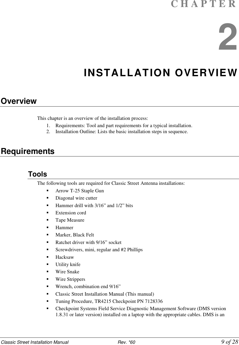
![Classic Street Installation Manual Rev. *60 12 of 28 If mounted in a plenum space, proper plenum rated wiring and plenum rated enclosures are required. The maximum operation temperature should be no more than 40℃. Note: For more information about power supplies, please see “Power Supplies” on Appendix 2. Antenna Mounting Antennas are typically not mounted until after the finished flooring is in place. Mounting Hardware For mounting on Concrete Floor Utilize two (2) 1.3cm [.5in.] anchor bolts per antenna. Figure 2 Anchor Bolt (Concrete Mounting) Wood Floor Utilize two (2) 1.3cm [.5in] lag bolts per antenna. Figure 3 Lag Bolt (Wood Mounting)](https://usermanual.wiki/Checkpoint-Systems/LIB24TZ.Manual/User-Guide-1621304-Page-12.png)
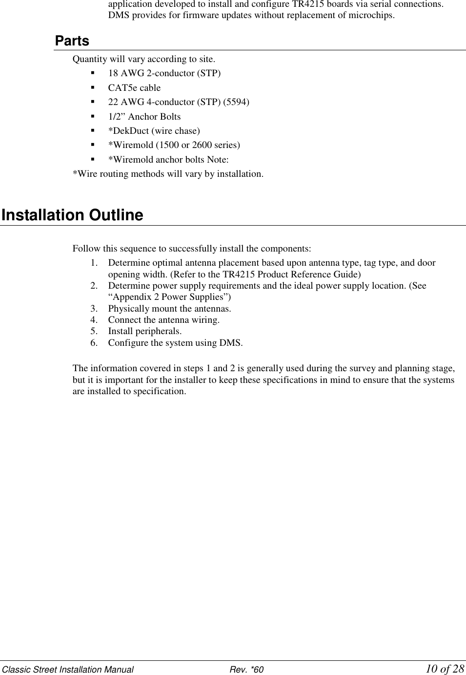
![Classic Street Installation Manual Rev. *60 13 of 28 Wire Routing Methods of Wire Routing The cabling between PSB and SSB has to be routed either under floor or through floor wiremold. “Up & Over” routing method is not permitted for cabling between PSB and SSB. Figure 4 Methods of Wire Routing Floor Trench: Typically 1.3cm [.5in.] wide by 3.8cm [1.5in.], but an increase in dimensions is recommended for more than two antennas. Wiremold: 1500 or 2600 series wire mold can be utilized. Typically wire mold is not used within customer traffic areas, so a typical placement is from the outside of the antennas to the doorframe. Conduit: 2.5cm [1in.] diameter conduit can be utilized in new construction situations. It is recommended that swept 90 degree angles are used, and that pull-strings are provided by the conduit installer. Wall / Mullion: Wires can be contained within mullions, and hollow walls for vertical wire runs. Dek-Duct / Panduit: Wires can be contained within surface mount Dek-Duct or Panduit for vertical wire runs. WARNING: Any wiring in plenum areas must be plenum rated. Additionally, ensure that the wire is installed in accordance with applicable (local/national) electrical codes. Correct Wire Routing (A) Incorrect Wire Routing (B) OR](https://usermanual.wiki/Checkpoint-Systems/LIB24TZ.Manual/User-Guide-1621304-Page-13.png)
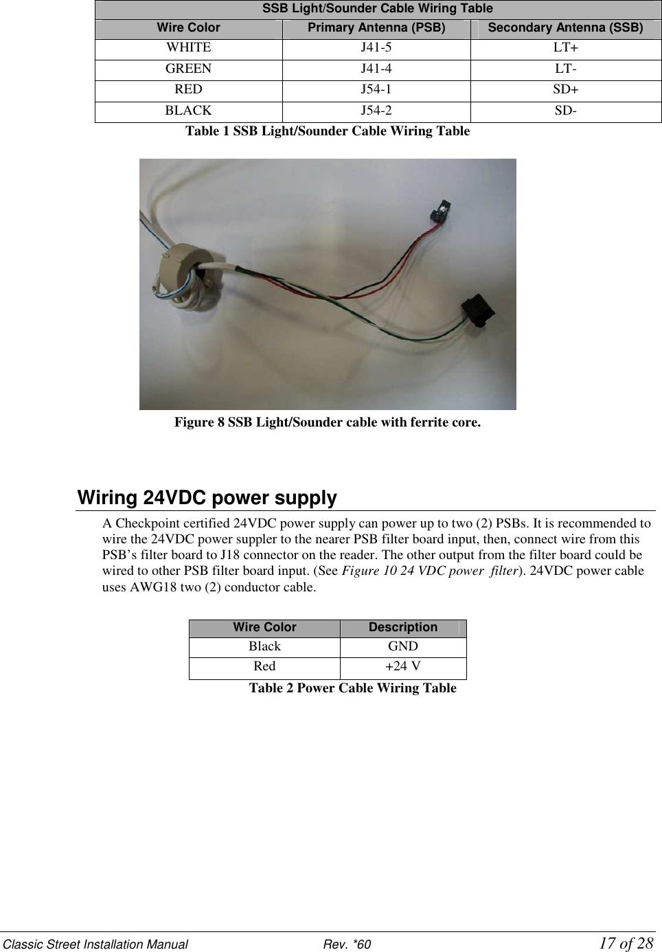
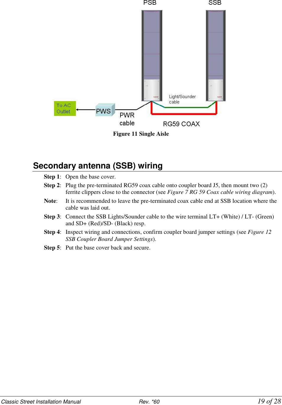
![Classic Street Installation Manual Rev. *60 16 of 28 Wiring between PSB/SSB There are only two (2) wires connected between PSB and SSB. They are 1) RG59 coax cable and 2) SSB Light/Sounder cable (22 AWG 4-conductors (STP) (5594)) RG59 Coax Cable: A 13ft long, one end pre-terminated RG59 coaxial cable is packed with SSB antenna. It connects the coupler boards (J5) in the primary antenna (PSB) and in the secondary antenna (SSB). It is recommended to leave the pre-terminated end at the SSB. The installer has to terminate the other end at the primary antenna. 1. Strip the coax cable jack off for about 19mm [3/4in] at the un-terminated end, as shown in Figure 7 RG 59 Coax cable wiring diagram (A). 2. Separate and twist the shield braid tightly, leaving now loose strands. 3. Strip the center conductor to about 6 mm [1/4 in], insert it into connector pin #1, then tighten it with screwdriver. 4. Insert the twisted shield braid to the connector pin #2, and secure it with screwdriver. 5. Clamp 2 ferrite cores on each ends (PSB and SSB). 6. Figure 7 RG 59 Coax cable wiring diagram (B) shows the RG59 cable assembly been completely terminated with ferrite cores clamped on both ends. 12312332113 ft19mm[3/4in]25mm[1 in]12mm[1/2in](A)(B)Center ConductorShield Conductor321 Figure 7 RG 59 Coax cable wiring diagram SSB Light/Sounder Cable It is recommended to use CKP standard field service truck stock 4-conductor wire (AWG22). For the lights the white wire connects LT+ terminal and green wire connects LT- terminal. For the sounder the red wire connects to SD+ terminal and the black wire connects to the SD- terminal. The SSB light/sounder cable must mount a cylindrical ferrite at each end in PSB and SSB. A ferrite core with three turns is attached to each end.](https://usermanual.wiki/Checkpoint-Systems/LIB24TZ.Manual/User-Guide-1621304-Page-16.png)
![Classic Street Installation Manual Rev. *60 26 of 28 A P P E N D I X 2 POWER SUPPLIES Overview This appendix covers all available (US and EU) TR4215 Street compatible power supplies. Details Power supplies have an output of +24 VDC. Requirements In the US, if the power supply is to be installed in a plenum (HVAC ventilation) area, the Globtek GS-599ES(R) and the Globtek GS-599MC-KIT(R) must be installed. Capacity The following power supplies can provide power for up to two aisle systems: Globtek GS-599 UF Globtek GS-599ES(R) EOS LFZVC65SG24E EOS- LFEVC65NS24PL (PN: 10102495) The following power supply can provide power for one aisle systems: EOS LFZVC36FS24S91 Power Supply Used in United States Model The US market uses the following power supply types: 1. Globtek GS-599ES(R) (PN: 7116509) Standard power supply rated for use in plenum areas. Note: For use in plenum areas, the Globtek GS-599MC-KIT(R) must be used in conjunction with the Globtek GS-599ES(R). Dimensions Width: 10.50cm [4.13in] Length: 15.24cm [6.00in] Height: 8.64cm [3.40in]](https://usermanual.wiki/Checkpoint-Systems/LIB24TZ.Manual/User-Guide-1621304-Page-26.png)
![Classic Street Installation Manual Rev. *60 27 of 28 2. EOS- LFEVC65NS24PL (PN: 10102495) Note: Dimensions Width: 5.8 cm [2.284in] Length: 13.3 cm [5.236in] Height: 2.9 cm [1.152in] Weight 350 grams (12.35 ounces)](https://usermanual.wiki/Checkpoint-Systems/LIB24TZ.Manual/User-Guide-1621304-Page-27.png)
![Classic Street Installation Manual Rev. *60 28 of 28 Power Supply Used In Europe Model The EU market uses one power supply types: EOS LFZVC36FS24S91 (PN: 7683707) Dimensions Length: 8.89cm [3.50in] Width: 2.42cm [0.95in] Height: 4.47cm [1.75in]](https://usermanual.wiki/Checkpoint-Systems/LIB24TZ.Manual/User-Guide-1621304-Page-28.png)