Checkpoint Systems LIBUHX Liberty UHX Pedestals User Manual Liberty UHX On site Upgrade Guide
Checkpoint Systems Inc Liberty UHX Pedestals Liberty UHX On site Upgrade Guide
rev users manual

Liberty
™
UHX Pedestal
for
Retail
Upgrade Guide
iii
Copyright © 2004 by Checkpoint Systems, Inc.
Released May 6, 2005.
Published by:
Checkpoint Systems Inc.
101 Wolf Drive
Thorofare, NJ 08086
Document revision information
Upgrade Guide for the Liberty UHX Pedestals
4th Edition - 2-9-2005
5th Edition - 3-18-2005
6th Edition - 5-6-2005
Trademarks
Checkpoint and Strata are a registered trademark and Liberty is a trademark of Checkpoint
Systems, Inc.
Other product and company names herein may be trademarks of their respective owners.
Other products © or ® their respective manufacturers or copyright holders.
Copyright and Warranty Information
The information in this manual is subject to change without notice.
Because of the changing nature of this product information presented in the Upgrade Guide,
Checkpoint Systems, Inc. is not liable for any omissions, misstatements, or other errors of
information.
The information presented in the Upgrade Guide may not be copied, used or disclosed to others for
the purpose of procurement or manufacturing without the written permission of Checkpoint
Systems, Inc. This manual and the products discussed in this manual are the exclusive property of
Checkpoint Systems Inc. Copyright laws of the United States protect all information and products.
Copyright© 2001, 2002, 2003 and 2004 Checkpoint Systems, Inc. All rights reserved.

iv
Important Information to our Users in North America
FCC Regulatory Compliance Statement
Checkpoint Systems, Inc., offers Radio Frequency Identification Products that have been FCC certified or
verified to 47 CFR Part 15 Subparts B/C and/or 47 CFR Part 18. Appropriately, one of the following labels
will apply to the approval:
NOTE
: This equipment has been tested and found to comply with the limits for a class A digital
device, pursuant to Part 15 of the FCC Rules. These limits are designed to provide reasonable
protection against harmful interference when the equipment is operated in a commercial environment.
This equipment generates, uses, and can radiate interference to radio communications. Operation of
this equipment in a residential area is likely to cause harmful interference in which case the user will be
required to correct the interference at his own expense.
- OR -
This device complies with Part 15 of the FCC Rules. Operation is subject to the following two
conditions: (1) including this device may not cause harmful interference, and (2) this device must
accept any interference received, including interference that may cause undesired operation, which
may include intermittent decreases in detection and/or intermittent increases in alarm activity.
- OR -
NOTE: This equipment has been tested and found to comply with the limits for a miscellaneous type
ISM device, pursuant to Part 18 of the FCC Rules. This equipment generates, uses, and can radiate
radio frequency energy and, if not installed and used in accordance with the instruction manual, may
cause harmful interference to radio communications. However, there is no guarantee that interference
will not occur in a particular installation. If this equipment does cause harmful interference to radio
communications reception, which can be determined by turning the equipment off and on, please
contact Checkpoint Systems, Inc., at 1 (800) 257-5540 for further assistance.
Equipment Safety Compliance Statement
Checkpoint Systems Radio Frequency Identification products have been designed to be safe during normal
use and, where applicable, certain components of the system or accessory sub-assemblies have been
certified, listed or recognized in accordance with
one or more
of the following Safety standards: UL 1012,
UL 1037, UL 1310, UL 60950-1, CSA C22.2 No. 205, CSA C22.2 No. 220, CSA C22.2 No. 223, CSA
C22.2 No. 60950-1. Additional approvals may be pending.
WARNING:
Changes or modifications to Checkpoint’s Radio Frequency Identification (RFID)
equipment not expressly approved by the party responsible for assuring compliance could void the user’s
authority to operate the equipment in a safe or otherwise regulatory compliant manner.

1
Introduction 1-1
Removing Existing Pedestals 2-1
Removing QS2000 Pedestals 2-2
Estimated completion time 2-3
Removing bumper posts 2-3
Estimated completion time 2-3
Removing Strata PX Pedestals 2-4
Estimated completion time 2-5
Removing bumper posts 2-5
Estimated completion time 2-5
Removing Liberty PX Pedestals 2-6
Estimated completion time 2-7
Installing Liberty UHX Pedestals 3-1
Cutting new wiring channel 3-1
Estimated completion time 3-1
Electrical and Network Wiring 3-2
Wiring for front entrance 3-3
Wiring for employee entrance pedestal 3-4
Estimated completion time 3-5
Installing the pedestal 3-6
Estimated completion time 3-7
Liberty UHX Installation Checklist 4-1
Installation Checklist 4-1
General Information 4-1
Project Management/Marketing Scope 4-2
Checkpoint Contractor Scope 4-2
Checkpoint Technical Scope 4-2
Target Technical Scope 4-3
System Removal 4-3
System Installation 4-3
Follow up Procedures 4-4
Sample Door Layouts 4-7
Liberty UHX AR-400 Setup
Instructions 5-1
Equipment 5-1
Post-Installation Procedure 5-1
Verification of Power Settings 5-5
Table of Contents
2

1-1 Liberty UHX Upgrade Guide
CHAPTER
C
HAPTER
0
I
NTRODUCTION
This Guide allows you to upgrade existing installations of QS2000, Strata PX and Liberty
PX pedestals to the new Liberty UHX pedestal. The new Liberty UHX pedestals can read
both EAS and UHF/RFID tags simultaneously.
The following upgrade scenarios are covered in this document:
• Removing the existing pedestals
•QS2000 pedestals (EAS)
•Strata PX pedestals (EAS)
•Liberty PX pedestals (EAS)
• Installing the new Liberty UHX pedestals (EAS and RFID)
•Cutting the new wiring channel
•Installing the power supplies
•Running the electrical and network wiring
•Installing the new Liberty UHX pedestals
An upgrade is completed by Checkpoint in an expeditious manner from the legacy
pedestals without disruption to the store operations for extended periods of times.
All upgrades will take place outside of store hours during a period of time mutually agreed
upon by both parties.
Similar to the initial installation of either the Liberty PX, Strata PX or QS2000 pedestals,
the process of upgrading to the Liberty UHX pedestals requires the presence of
Checkpoint Technicians, Target personnel, and Checkpoint contractors. Checkpoint is
responsible for carefully screening and engaging the Checkpoint contractor prior to the
scheduled installation date. In some instances, a licensed electrician may be required.
Whether an electrician is required or not will depend on the local building codes.
An upgrade plan includes installing the Liberty UHX antennas and fully configuring and
testing the EAS functionality of the antennas prior to the store opening. Once the EAS
functionality of the antennas is confirmed, the Liberty UHX pedestals will be configured
and tuned for full UHF functionality.

Introduction: 1-2
The following table outlines the responsibilities for each installation group. The tasks are
listed in the order they should be completed.
*Note: Replacement mats are ordered and maintained by Target. It is important for
Checkpoint personnel to review the site survey and determine necessity of mats. If
replacement mats are required, Checkpoint personnel must notify Target to have mats
ordered and delivered in time for the upgrade to the existing pedestals. As a precautionary
measure, Checkpoint technicians will carry a 15 by 10 foot mat to all installations.
Table 0.1
Installation/upgrade task list
Responsibility (Task) Installation Group
*Acquiring replacement mat, if necessary Target
Removing existing pedestals Checkpoint
Repairing old drill holes, if necessary Checkpoint Contractor
Removing existing floor mats Checkpoint Contractor
Removing any bumper posts, if necessary Checkpoint Contractor
Filling in old bumper post holes, if necessary Checkpoint Contractor
Cutting new floor channel (trench) Checkpoint Contractor
Installing walker duct Checkpoint Contractor
Installing power supply boxes Checkpoint Contractor
Running power from ceiling to floor Checkpoint
Running power in walker duct to pedestals base Checkpoint
Crimping power wires and installing connectors Checkpoint
Running CAT 5 network cable and terminate at the power supply with
appropriate length
Target
Running CAT 5 network cable from power supply to floor Checkpoint Contractor
Running CAT 5 network cable in walker duct to pedestal base Checkpoint
Installing connectors on the CAT 5 network cable Target
Testing network connectivity Target
Connecting CAT 5 cable to pedestal riser Checkpoint
Connection power to pedestal riser Checkpoint
Installing new pedestals Checkpoint
Replacing floor mats, if necessary Checkpoint Contractor
Testing new pedestals for EAS Checkpoint
Testing new pedestals for UHF Checkpoint

2-1 Liberty UHX Upgrade Guide
CHAPTER
C
HAPTER
0
R
EMOVING
E
XISTING
P
EDESTALS
In order to install the Liberty UHX pedestals, you must first remove the existing legacy
pedestals. This chapter provides detailed instructions for removing the following legacy
pedestals:
• QS2000 (EAS) - See “Removing QS2000 Pedestals” on page 2-2.
• Strata PX (EAS) - See “Removing Strata PX Pedestals” on page 2-4.
• Liberty PX (EAS) - See “Removing Liberty PX Pedestals” on page 2-6.
Each of these procedures is very straight-forward and can be accomplished by Checkpoint
Technicians. It is estimated that removing a single pedestal would take a Checkpoint
Technician approximately 15 minutes. This time can vary.
Removing Existing Pedestals: Removing QS2000 Pedestals 2-2
Removing QS2000 Pedestals
To remove existing QS2000 pedestals, complete the following.
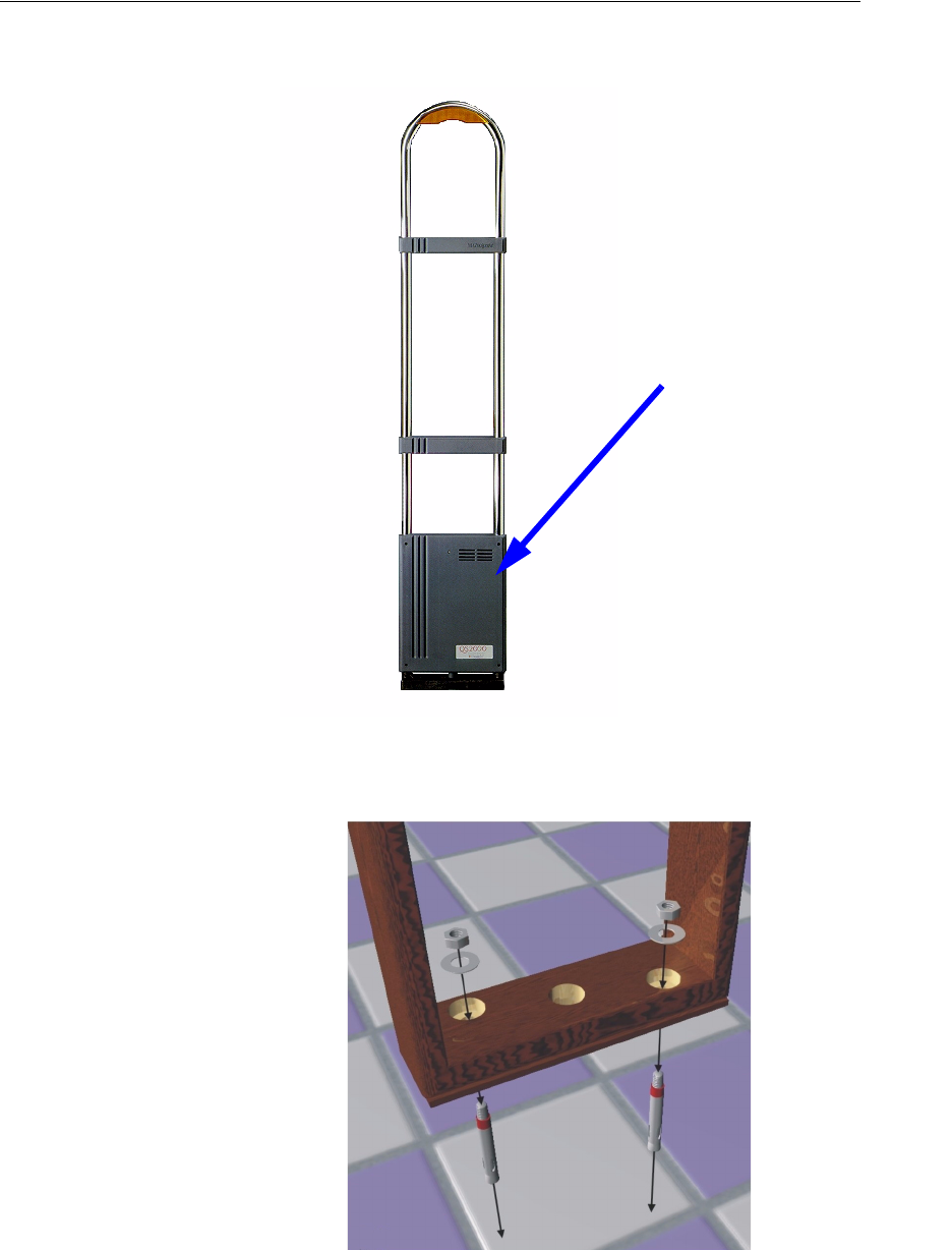
1Checkpoint Technician removes the plastic covering from the QS2000 pedestal.
Figure 2.1
QS2000 pedestal.
2Checkpoint Technician unbolts and removes existing QS2000 pedestals.
Figure 2.2
The QS2000 pedestal is installed with two 3 inch by 1/2 inch anchor bolts.
plastic covering

2-3 Liberty UHX Upgrade Guide
3Checkpoint Technician removes the existing bolt anchors in one of the following ways:
•Break
•Cut
•Pound down
4Since the footprint of all QS pedestals is 12 inches by 3 1/2 inches, the existing bolt
anchor holes will need to be filled in because these holes cannot be reused for Liberty
UHX installations.
Estimated completion time
Removal of the legacy QS2000 pedestal will take approximately 30 minutes per single
pedestal.
Removing bumper posts
QS2000 pedestal may have a bumper post installed on either side of the pedestal to protect
the pedestal from damage. These bumper posts should be removed and the post holes
filled in with concrete. Instead of bumper posts, the new Liberty UHX pedestals are
installed on top of metal risers. The riser elevates the base of the Liberty UHX pedestal off
of the floor to protect it from being damaged.
To remove the existing bumper posts:
1Checkpoint contractors remove flooring.
2Checkpoint contractors remove both bumper posts.
3Checkpoint contractors fill in bumper post holes with concrete.
Estimated completion time
Removal of each bumper post will take approximately 15 minutes plus time for concrete.
This can vary by Checkpoint contractor.
Removing Existing Pedestals: Removing Strata PX Pedestals 2-4
Removing Strata PX Pedestals
To remove existing Strata PX pedestals, complete the following.
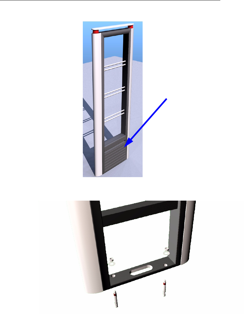
1Checkpoint Technician removes the plastic covering from the Strata PX pedestal.
Figure 2.3
Strata PX pedestal.
2Checkpoint Technician unbolts and removes existing Strata PX pedestals.
Figure 2.4
The Strata PX pedestal installed with two 3 inch by 1/2 inch anchor bolts.
plastic covering

2-5 Liberty UHX Upgrade Guide
Estimated completion time
Removal of legacy Strata PX pedestal will take approximately 15 minutes per single
pedestal.
Removing bumper posts
Strata PX pedestal may have a bumper post installed on either side of the pedestal to
protect the pedestal from damage. These bumper posts should be removed and the post
holes filled in with concrete. Instead of bumper posts, the new Liberty UHX pedestals are
installed on top of metal risers. The riser elevates the base of the Liberty UHX pedestal off
of the floor to protect it from being damaged.
To remove the existing bumper posts:
1Checkpoint contractors remove flooring.
2Checkpoint contractors remove both bumper posts.
3Checkpoint contractors fill in bumper post holes with concrete.
Estimated completion time
Removal of each bumper post will take approximately 15 minutes plus time for concrete.
This can vary by Checkpoint contractor.
Removing Existing Pedestals: Removing Liberty PX Pedestals 2-6
Removing Liberty PX Pedestals
To remove existing Liberty PX pedestals, complete the following.
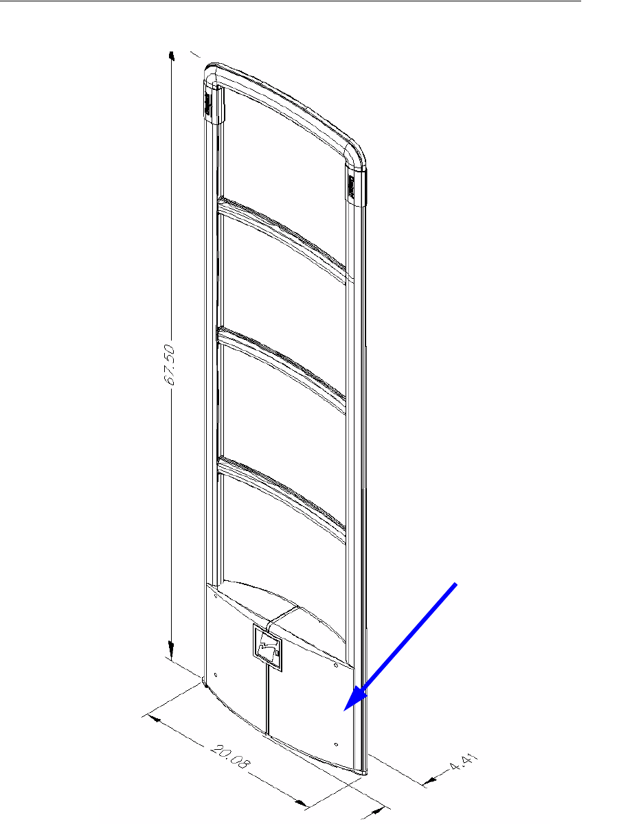
1Checkpoint Technician removes the plastic covering from the Liberty PX pedestal.
Figure 2.5
Liberty PX pedestal
plastic covering
2-7 Liberty UHX Upgrade Guide
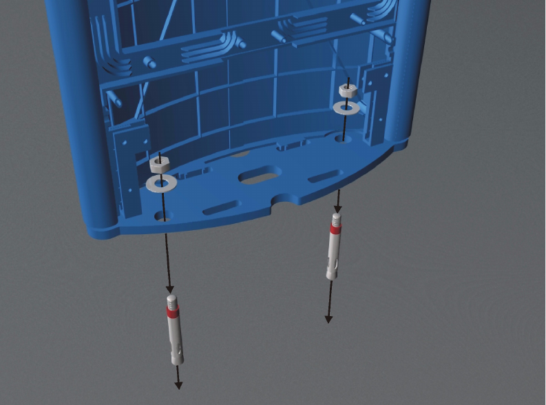
2Checkpoint Technician unbolts and removes existing Liberty PX pedestals.
Figure 2.6
Liberty PX pedestal is installed with two 3 inch by 1/2 inch anchor bolts.
Estimated completion time
Removal of legacy Liberty PX pedestal will take approximately 15 minutes per single
pedestal.
Removing Existing Pedestals: Removing Liberty PX Pedestals 2-8
Notes

3-1 Liberty UHX Upgrade Guide
CHAPTER
C
HAPTER
0
I
NSTALLING
L
IBERTY
UHX P
EDESTALS
Once the legacy pedestals are removed, you are ready to install the new Liberty UHX
pedestals.
The installation of the new Liberty UHX pedestal includes the following:
• Cutting a new wiring channel
• Running the electrical and network wiring
• Installing the new Liberty UHX pedestal
Placement of the Liberty UHX pedestals coincides with normal placement of the Liberty
PX pedestals.
Cutting new wiring channel
Checkpoint contractors will cut floor trench in the center of existing EAS pedestal
infrastructure and back fill trench upon completion of wire installations.
Estimated completion time
The cutting of a 35-foot floor channel will take approximately 60 minutes. This can vary
by Checkpoint contractor.
Installing Liberty UHX Pedestals: Electrical and Network Wiring 3-2
Electrical and Network Wiring
For the new Liberty UHX pedestal the following wiring is required:
• Electrical - 1 gauge wire (shielded). 1 wire required per pedestal.
• Network - CAT 5 or 5e cable (un-shielded twisted pairs). 1 cable required per pedestal.
To complete the network and electrical installation and wiring,
1 Checkpoint contractor installs one or two additional shelves in the ceiling on one side
of the entry way or attaches the 3 power supplies directly to the studded wall.
•Each shelf must support two (2) power supplies along with all required controls.
•Each shelf must support 1 network access point.
•Six (6) power supplies are required for a six (6) pedestal installation. Each supply
powers a single pedestal.
2 Checkpoint contractor ensures that the power supplies are within AC power cord
range (4 feet) of the outlet box.
A licensed electrician may be required for this part of the installation. Please consult local
building codes to determine if a licensed electrician is required.
3-3 Liberty UHX Upgrade Guide
Wiring for front entrance
The network and electrical wiring for all six pedestals originate from the power supply and
network access point installed in the ceiling above side of the entry way on the studded
wall.
The power cabled are shipped in standard 100” lengths with connectors attached to one
end. The other end of the power cable will have connectors added at the site. The power
supply also ships with the connector attached.
The following tasks should be completed by Target IT staff prior to the start of the
installation by Checkpoint Technicians.
1Target Technician runs CAT 5 cables from the homerun area and terminates at the
power supply with appropriate length.
2Target Technician installs router and network connection near both shelves.
The following tasks are completed on the installation date by a Checkpoint Technician and
a Checkpoint contractor.
1Checkpoint contractor runs CAT 5e network cable into a 0.5” PVC conduit to run from
power supply to floor.
2Checkpoint Technician inserts wiring into 1.00" PVC conduit to run from ceiling to
trench. This PVC conduit is recommended, but is not electrically required. The factory
installed connector should remain at the portion of the PVC pipe nearer the ceiling.
Fish the rest of the cable through the PVC pipe towards the floor.
3 Checkpoint contractor installs walker duct in trench.
4Checkpoint Technician runs the necessary power cable through the walker duct to the
junction boxes at the foot of each pedestal.
5Checkpoint Technician crimps the wires into a connector.
6Checkpoint Technician runs the CAT 5e cables through the walker duct to junction
boxes at the foot of each pedestal.
7Plug the factory installed connector into the power supply.
The following tasks must be completed by Target IT staff after the trench has been cut and
the CAT 5 cable run in the walker duct by the Checkpoint Technician.
1Target Technician crimps the wires into an RJ-45 surface mount jack.
•Pins 1 and 2 - orange pair - white, orange, white
•Pins 3 and 6 - green pair - white, green, white
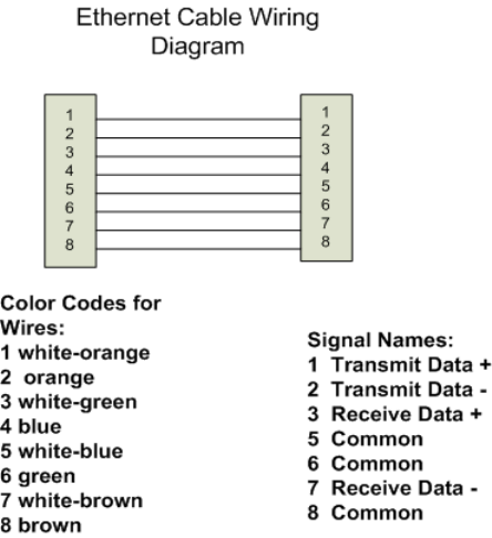
Installing Liberty UHX Pedestals: Electrical and Network Wiring 3-4
•Blue pair and brown pair are not used.
2Target Technician tests the CAT 5 cable for network connectivity.
3 Checkpoint contractor back-fills floor trench (over top of wiring).
Wiring for employee entrance pedestal
Currently there are 2 antenna pedestals at the employee entrance. These 2 pedestals are
replaced by one single Liberty UHX pedestal to be installed near the wall that contains the
power supply. The following wiring instructions only apply to one pedestal.
The following tasks should be completed by Target IT staff prior to the start of the
installation by Checkpoint Technicians.
1Target Technician runs CAT 5 cables from the homerun area and terminates at the
power supply with appropriate length.
2Target Technician installs router and network connection near both shelves.
The following tasks are completed on the installation date by a Checkpoint Technician and
a Checkpoint contractor.
1Checkpoint contractor runs CAT 5e network cable into a 0.5” PVC conduit to run from
power supply to floor.
2Checkpoint Technician inserts wiring into 1.00" PVC conduit to run from ceiling to
floor. This PVC conduit is recommended, but is not electrically required. The factory
installed connector should remain at the portion of the PVC pipe nearer the ceiling.
Fish the rest of the cable through the PVC pipe towards the floor.
3Checkpoint Technician runs necessary power cable to the junction box at the foot of
the pedestal.
4Checkpoint Technician crimps power wires into a connector.
5Checkpoint Technician runs CAT 5e cable to junction boxes at the foot of each
pedestal.
3-5 Liberty UHX Upgrade Guide
6Plug the factory installed connector into the power supply.
The following tasks must be completed by Target IT staff.
1Target Technician crimps the wires into an RJ-45 surface mount jack.
•Pins 1 and 2 - orange pair - white, orange, white
•Pins 3 and 6 - green pair - white, green, white
•Blue pair and brown pair are not used.
2Target Technician tests the CAT 5 cable for network connectivity.
Estimated completion time
Conduit preparation will take approximately 120 minutes. This can vary by Checkpoint
contractor.
Installing Liberty UHX Pedestals: Installing the pedestal 3-6
Installing the pedestal
Once the wiring is completed, you are ready to install the actual Liberty UHX pedestal.
New anchor bolt holes are only required if the legacy pedestals are QS2000s. The bolt
locations for the QS2000 were closer together than those of the Strata PX and Liberty PX.
Since the bolt hole locations for the Strata PX and Liberty PX are identical to those of the
Liberty UHX, the existing bolts can be reused.
1For replacement of QS2000 pedestals only, Checkpoint Technician drills new holes
and installs anchor bolts.
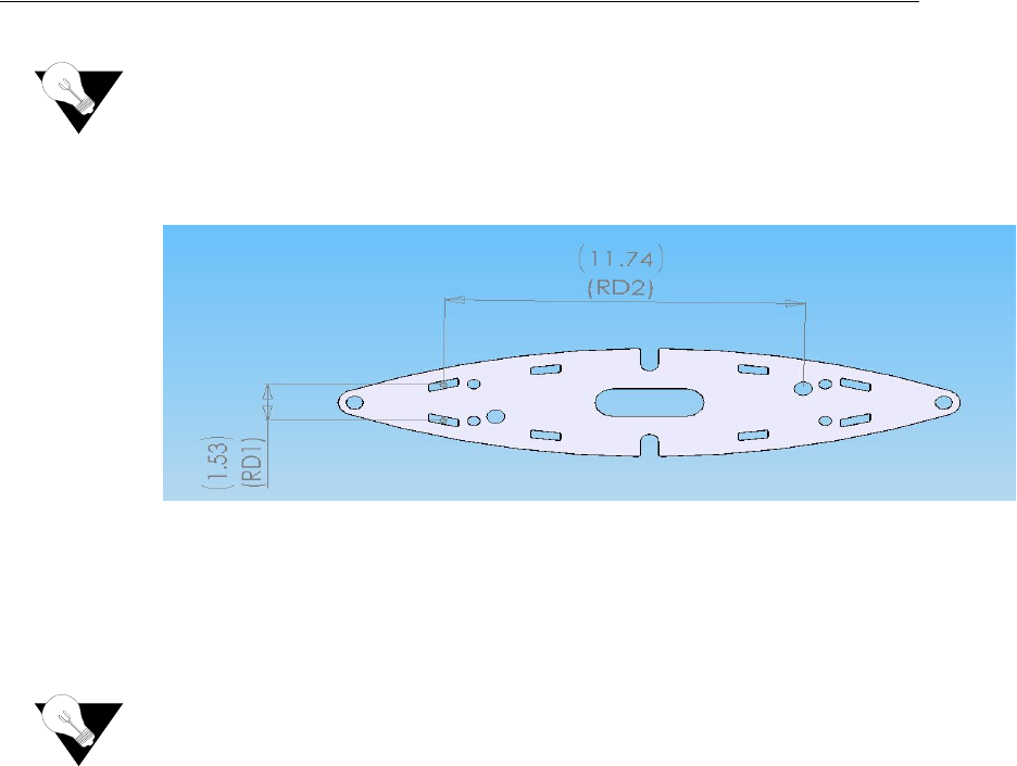
2If larger raised base plates are used, cut the floor mats or existing flooring material to
accommodate the larger raised base plates (Checkpoint contractor).
In certain instances, longer and wider raised base plates are required. This varies by store
location.
3Checkpoint contractor repairs flooring.
It may be necessary to install new flooring or replacement mats due to cuts and holes
(from the previous pedestals).
4Checkpoint Technician bolts down the raised base plate assembly to the previously
installed anchor bolts.
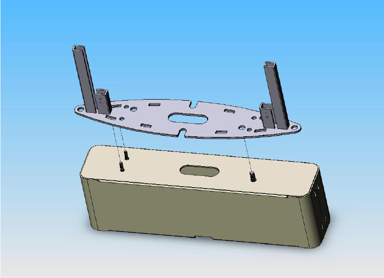
3-7 Liberty UHX Upgrade Guide
5Checkpoint Technician bolts down Liberty UHX pedestals to the raised base plate
assembly.
6Checkpoint Technician connects the power to the Liberty UHX pedestal.
7Checkpoint Technician connects the network cable to the Liberty UHX pedestal.
8Checkpoint Technician configures, tunes and tests the Liberty UHX pedestals.
Estimated completion time
Approximate install time for a single pedestal is 60 minutes if new anchor bolt holes need
to be drilled. This will be for an upgrade from a QS2000 pedestal. This can vary by
Checkpoint contractor.
Approximate install time for a single pedestal is 30 minutes if an upgrade from Liberty PX
or Strata PX that does not include drilling new bolt holes. In most instances, this type of
upgrade will not include drilling new bolt holes. This can vary by Checkpoint contractor.
Installing Liberty UHX Pedestals: Installing the pedestal 3-8
NOTES

4-1 Liberty UHX Upgrade Guide
CHAPTER
C
HAPTER
0
L
IBERTY
UHX I
NSTALLATION
C
HECKLIST
A site survey will be conducted by a team composed of both customer and Checkpoint
personnel. Once a site survey is reviewed by both parties, Checkpoint will detail store
specific information in a customer-specific version of the sample Installation Checklist
shown below.
Installation Checklist
General Information
• ___________________ and Checkpoint will collaborate on upgrading existing EAS
installed Target Stores to Liberty UHX with Riser Baseplates.
• The installation start time will be ____ PM for both Checkpoint and _____________.
• Store hours may vary; work will begin at the Store Manager’s discretion. Speaking to
the Store Manager prior to the installation time is recommended.
• If the Checkpoint contractors are not onsite by ____ PM, the Checkpoint Technician
should contact __________________’s POC (Point Of Contact).
• If Checkpoint is not onsite by ____ PM, the Checkpoint contractor should contact the
Onsite Project Coordinator.
Liberty UHX Installation Checklist: Installation Checklist 4-2
Project Management/Marketing Scope
• Door layouts are reviewed to verify project deliverables.
• Checkpoint personnel will be responsible for ensuring that all local building codes are
met.
• Checkpoint personnel will remind Target to buy replacement mats (if necessary) and to
ensure they are delivered in time for the upgrade of existing pedestals.
• Checkpoint personnel will work with Target to determine which riser baseplate is best
suited for this store location.
• As a precautionary measure, Checkpoint personnel will carry a 15 by 10 foot mat to all
installations.
Checkpoint Contractor Scope
• The Checkpoint contractor is responsible for the removal of any Alvarado protective
posts that are currently installed for the purpose of protecting the existing EAS
pedestals.
•Removing Alvarado posts usually requires that the posts are cut to floor level.
• The Checkpoint contractor installs walker duct and power supply boxes.
•Optional one or two additional shelves in the ceiling on one side of the entry way can
be built or Checkpoint contractor can attach the 3 power supplies directly to the
studded wall.
• The Checkpoint contractor runs the CAT 5 network cable from the power supply to the
floor.
• The Checkpoint contractor is responsible for performing floor cuts, as specified by the
Checkpoint Technician.
• The Checkpoint contractor is responsible for back filling all floor cuts after all
necessary wiring has been installed by Checkpoint.
• When performing floor cuts on ceramic tiled floors, cuts should only be made within
existing grout lines.
• Any specific instruction regarding mats, carpets, tiles, and any other special flooring
consideration will come from Target. (___________)
• The Checkpoint contractor should be prepared to replace VCT tiles in certain stores.
The tiles will be provided by Target.
Checkpoint Technical Scope
• Checkpoint Technician removes all legacy pedestals and related equipment.
• Checkpoint Technician is responsible for inserting wiring into 1.00” PVC conduit
(recommended) to run from ceiling to trench. Factory installed connector should remain
at the portion of the PVC pipe nearer the ceiling.
• Ensures that both the Cat 5 cable and power wiring is run in the walker duct from base
of stud wall to bottom of each pedestal.
• Checkpoint Technician crimps the wires into a connector.

4-3 Liberty UHX Upgrade Guide
• Once network connectivity is confirmed by Target, Checkpoint Technician connects
Cat 5 cable and power connection to pedestals.
• All Liberty UHX antennas are installed, configured and tested for full EAS
functionality by the Checkpoint Technician prior to store opening.
•Once EAS functionality of the antennas is confirmed, the Liberty UHX pedestals
will be configured and tuned for full UHF functionality.
• Checkpoint Technician ensures that completed checklist is faxed to Onsite Project
Coordinator and leaves a voice mail message for the Installation Scheduler, Onsite
Project Coordinator, Account Representative and the Project Manager.
Target Technical Scope
• Target is responsible for obtaining replacement mat prior to installation.
• Target IT staff must install router and network connections prior to the start of the
installation by Checkpoint technicians.
• Target IT staff is responsible for running Cat 5 network cable and terminating at the
power supply, installing connectors on the network cable and testing network
connectivity.
System Removal
• Do not remove any systems until the following conditions have been met:
1The intended Checkpoint shipment is verified.
2All Checkpoint contractors are present or accounted for, to include the individual
responsible for performing floor cuts, and the flooring contractor.
3The intended layout is assessed and shown to the Target store manager or person in
charge.
4Ensure that any new mats do not interfere with the motion of in-swinging doors.
• All removed equipment will be placed in a dumpster or compactor (ask the store
manager or person in charge).
System Installation
• Reference the appropriate configuration drawing later in this document. Each drawing
lists the relative store numbers.
• Systems should not exceed 72” on center.
• If there are layout issues, the store manager or person in charge should be consulted and
given options first. If a decision is not reached then the Onsite Project Coordinator
should be contacted, and then the Target Project Manager.

Liberty UHX Installation Checklist: Installation Checklist 4-4
Follow up Procedures
• Ensure that the installation checklist is filled out and initialed by Checkpoint, the
Checkpoint contractor, and the onsite Target representative. The checklist should be
faxed to the Onsite Project Coordinator.
• At the completion of the installation, a voice mail message must be left for the
Installation Scheduler, Onsite Project Coordinator, Account Representative, and
the Project Manager.
Table 4.1
Project contact information
Title Name Office Ext. Cell Pager
Account Scheduler
Onsite Project
Coordinator
[Customer Name]
Project Manager
[Checkpoint
Contractor Name]
Point of Contact
Account Manager
Project Manager
Table 4.2
Door installation checklist
Item
#Door Designation (i.e., North Door)
No? Explain
Below
Customer
Initials
Checkpoint
Initials
Checkpoint
Contractor
Initials
A New layout agreed upon?
B Replacement mat acquired? (if necessary)
C Existing pedestals removed and disposed of?
D Old drill holes repaired? (if necessary)
E Floor mats removed?
F Alvarado posts removed and disposed of?
G Alvarado bumper post holes filled in? (if necessary)
H New floor channel cut?
I Walker duct and power supply boxes installed?
J Power run from ceiling to floor?
K Power run through walker duct to pedestal riser?
L Power wires crimped and connectors installed?
M CAT 5 cable run and terminated at pedestal riser?
N CAT 5 cable crimped and connectors installed?
O Floor cut filled in?
P Floor covering repaired/installed/replaced?
Q Work area is clean and ready for store opening?
R Pedestals tested and properly functioning for EAS?
S Pedestals tested and properly functioning for UHF?

4-5 Liberty UHX Upgrade Guide
Explanation of negative responses or further comments
Table 4.3
Door installation checklist
Item
#Door Designation (i.e., North Door)
No? Explain
Below
Customer
Initials
Checkpoint
Initials
Checkpoint
Contractor
Initials
A New layout agreed upon?
B Replacement mat acquired, if necessary
C Existing pedestals removed and disposed of?
D Old drill holes repaired? (if necessary)
E Floor mats removed?
F Alvarado posts removed and disposed of?
G Alvarado bumper post holes filled in? (if necessary)
H New floor channel cut?
I Walker duct and power supply boxes installed?
J Power ran from ceiling to floor?
K Power ran from walker duct to pedestal riser?
L Wires crimped and power connectors installed?
M Cat 5 cable ran and terminated at pedestal riser?
N Floor cut caulked and/grouted?
O Floor covering repaired/installed/replaced?
P Work area is clean and ready for store opening?
Q Pedestals tested and properly functioning for EAS?
R Pedestals tested and properly functioning for UHF?
Explanation of negative responses or further comments
Table 4.2
Door installation checklist
Item
#Door Designation (i.e., North Door)
No? Explain
Below
Customer
Initials
Checkpoint
Initials
Checkpoint
Contractor
Initials

Liberty UHX Installation Checklist: Installation Checklist 4-6
***Please Fax completed checklist to _______________ at _________________.
Table 4.4
Door installation checklist
Item
#Door Designation (i.e., North Door)
No? Explain
Below
Customer
Initials
Checkpoint
Initials
Checkpoint
Contractor
Initials
A New layout agreed upon?
B Replacement mat acquired, if necessary
C Existing pedestals removed and disposed of?
D Old drill holes repaired? (if necessary)
E Floor mats removed?
F Alvarado posts removed and disposed of?
G Alvarado bumper post holes filled in? (if necessary)
H New floor channel cut?
I Walker duct and power supply boxes installed?
J Power ran from ceiling to floor?
K Power ran from walker duct to pedestal riser?
L Wires crimped and power connectors installed?
M Cat 5 cable ran and terminated at pedestal riser?
N Floor cut caulked and/grouted?
O Floor covering repaired/installed/replaced?
P Work area is clean and ready for store opening?
Q Pedestals tested and properly functioning for EAS?
R Pedestals tested and properly functioning for UHF?
Explanation of negative responses or further comments
Table 4.5
Project Signoff Sheet
Representative Name (Print) Signature
Target
Checkpoint
Checkpoint
Contractor
Table 4.6
Store specific information
Store # City: State: Date:
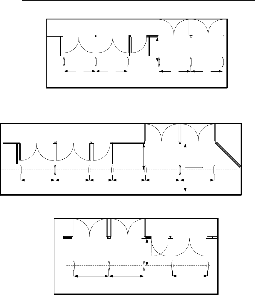
4-7 Liberty UHX Upgrade Guide
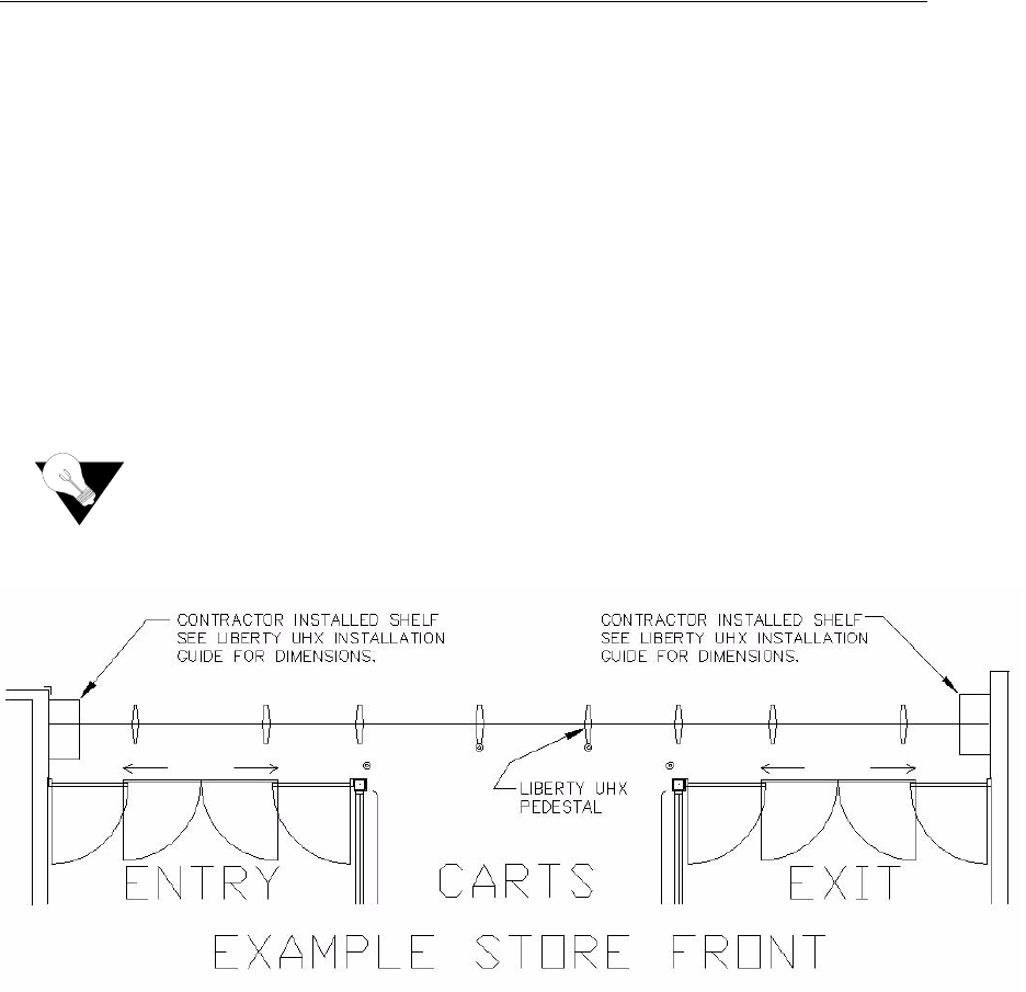
Sample Door Layouts
56"
72" 72"
72"72"
#282
56"
14' to Registers
72" 72"72"72" 4'-0"
5'-9"
#175,
72"
56"
72" 72"
#11, #26 [Mirrored Config: #12]
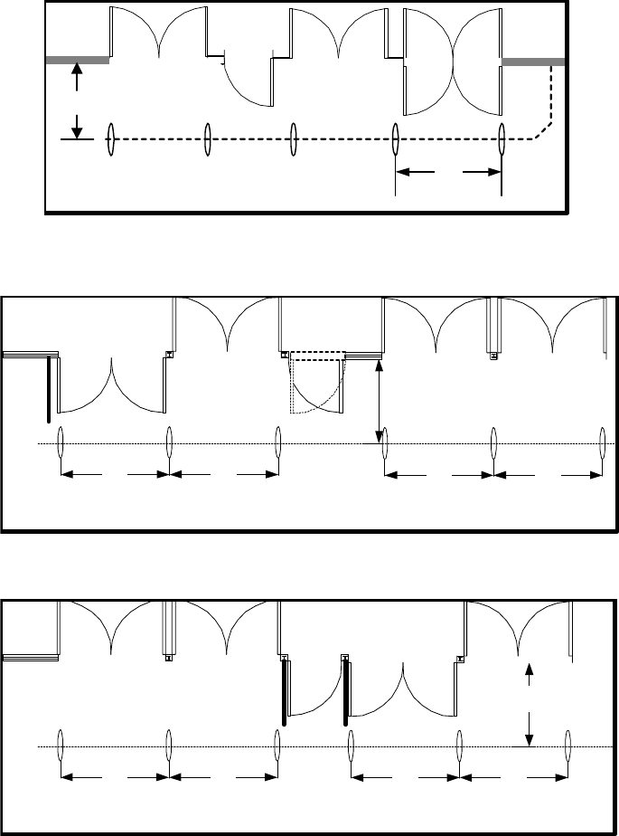
Liberty UHX Installation Checklist: Installation Checklist 4-8
#51
56"
72"
56"
72" 72"
72"72"
#346, #696, #748 - [Mirrored Config: #764, #826]
56"
72" 72"72"72"
#339

5-1 Liberty UHX Upgrade Guide
CHAPTER
C
HAPTER
0
L
IBERTY
UHX AR-400 S
ETUP
I
NSTRUCTIONS
The Liberty UHX AR-400 is configured via the configuration computer after installation
of the Liberty UHX pedestals.
Equipment
• Configuration computer, functional and powered
• Cat5 Cable, 3 ft. or longer
• Liberty UHX Pedestal
• Power Supply, Checkpoint Part No. 7375784
• Power Cord, Checkpoint Part No. 623532
Post-Installation Procedure
1Connect the Cat5 cable to AR-400 Ethernet port (using the access door).
2Connect the opposite end of the Cat5 cable to the configuration computers Ethernet
port.
3Power-up the computer.
4Change the IP address of the configuration computer to 192.168.0.1.
5Change the Subnet Mask of the configuration computer to 255.255.0.0.
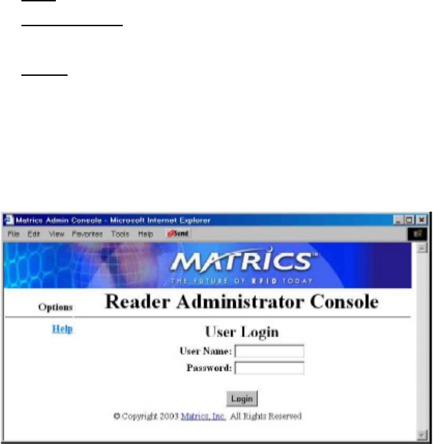
6Open Internet Explorer and type HTTP://192.168.127.254 in the address box and then
press Enter.
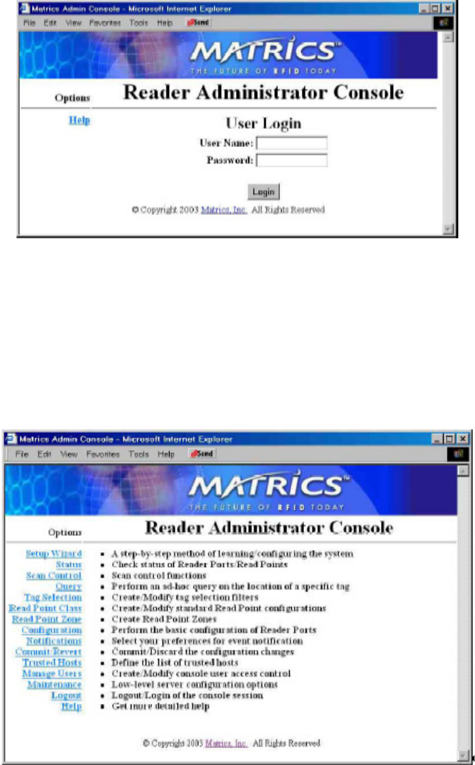
Liberty UHX AR-400 Setup Instructions: Post-Installation Procedure 5-2
You see the Reader Administrator Console screen.
Figure 5.1
User Login screen of the Reader Administrator Console
7Next to User Name:, type in the admin.
8Next to Password, type in the admin.
9Click Login.
OR
Press Enter.
Figure 5.2
Reader Administrator Console screen
5-3 Liberty UHX Upgrade Guide
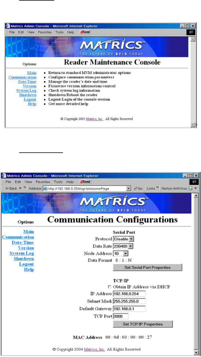
10 Click the Maintenance link on the left hand navigation bar.
You see the Reader Maintenance Console screen.
Figure 5.3
Reader Maintenance Console screen
11 Click the Communication link on the left hand navigation bar.
You see the Communication Configurations screen.
Figure 5.4
Communication Configurations screen
Liberty UHX AR-400 Setup Instructions: Post-Installation Procedure 5-4
12 Change the IP address to the specified IP address.
13 Change the Subnet Mask to the specified Subnet Mask.
14 Change the Default Gateway to the specified Default Gateway.
15 Click Set TCP/IP Properties.
16 Click the Main link on the left hand navigation bar.
17 Click the Commit/Revert link.
18 Click Commit.
19 Click the Logout link.
20 Power cycle the AR-400.
21 Verify the IP address change by opening Internet Explorer.
22 Type the specified IP address in the address box (HTTP://xxx.xxx.xxx.xxx) and then
press enter.
The following screen should appear.
Figure 5.5
User Login screen
23 Close Internet Explorer.
24 Unplug the cat-5 cable from the AR-400.
25 Close the access door.
5-5 Liberty UHX Upgrade Guide
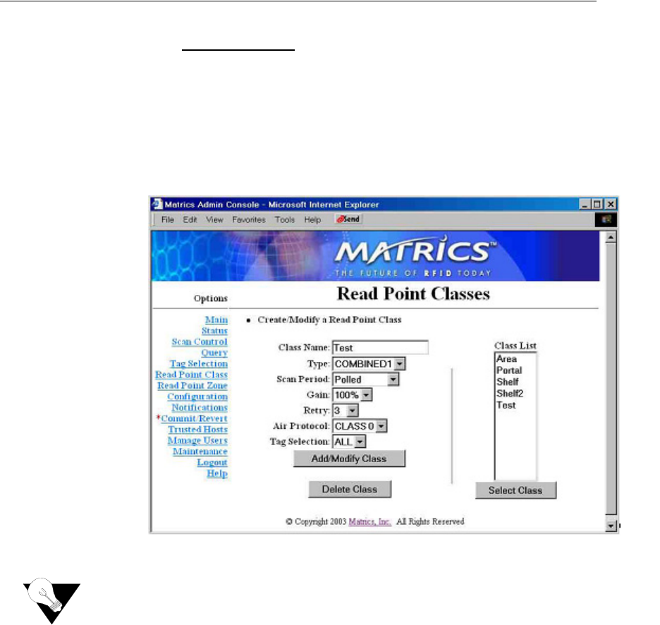
Verification of Power Settings
To verify the power settings, complete the following:
1Click the Read Point Class link on the left hand navigation bar.
2Select Area (from class list on the right hand side).
3Click Select Class.
4Verify Gain is set to 50%.
5Verify Retry is set to 1.
6Verify Air Protocol is set to ALL.
Figure 5.6
Read Point Classes screen
A Gain setting of 50% corresponds to a setting of 256 7 in the ART (Advanced Reader
Test console) program contained in the reader.
Liberty UHX AR-400 Setup Instructions: Verification of Power Settings 5-6
Notes