Checkpoint Systems MMRO7000 Performa Mullion Mount Proximity Reader User Manual

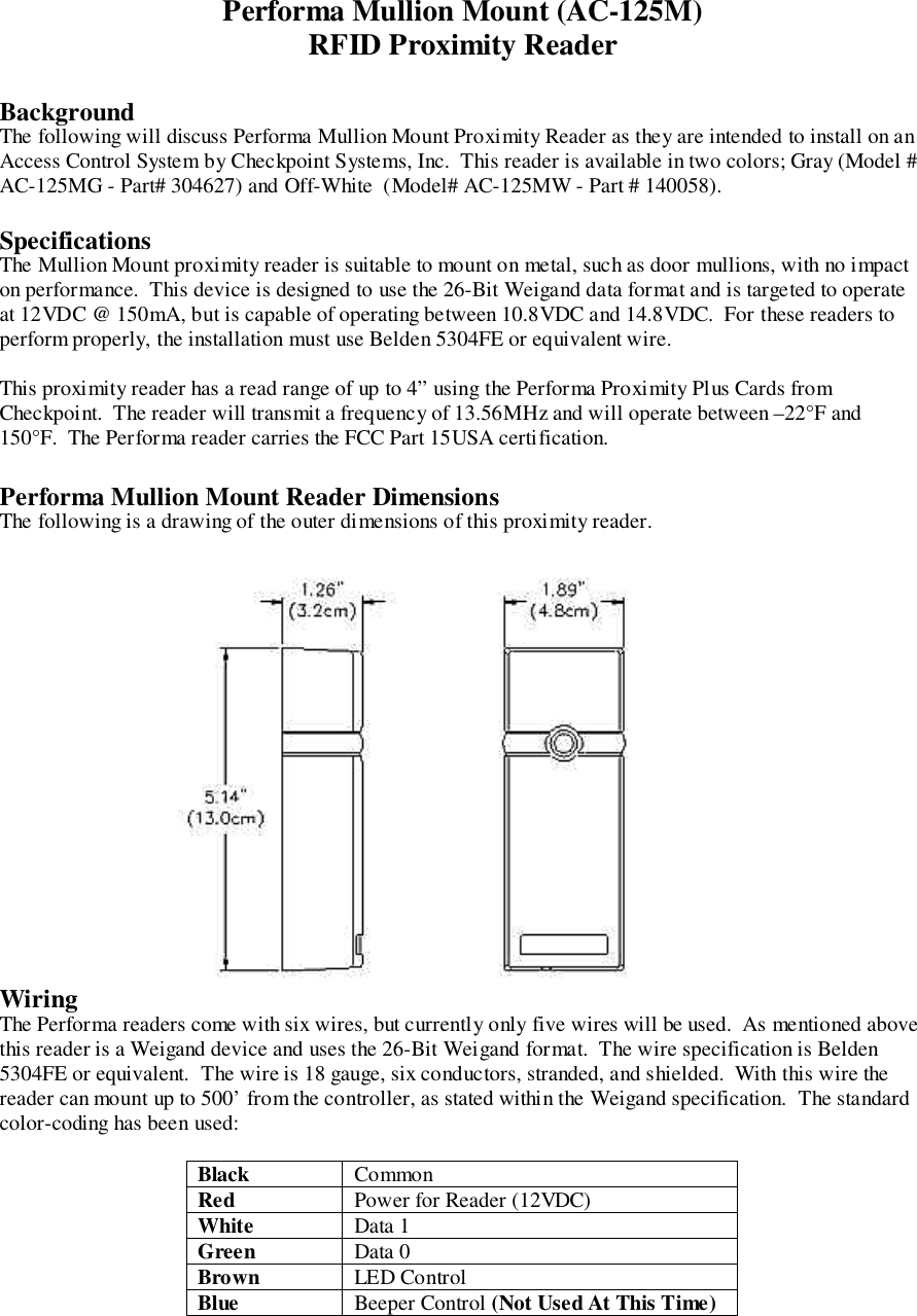
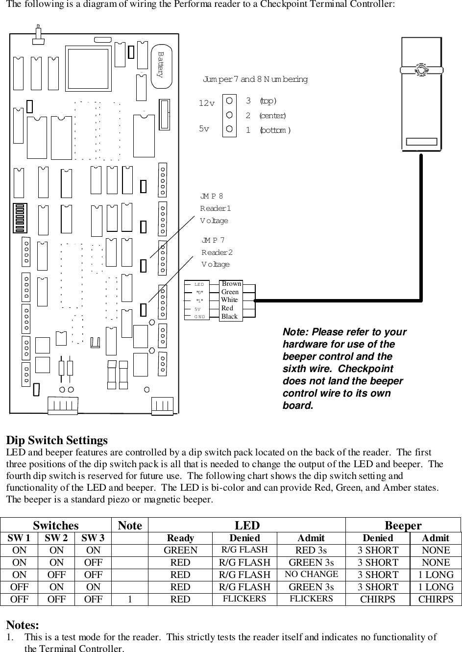
Checkpoint Systems Inc Performa Mullion Mount Proximity Reader

User Manual

Performa Mullion Mount (AC-125M)RFID Proximity ReaderBackgroundThe following will discuss Performa Mullion Mount Proximity Reader as they are intended to install on anAccess Control System by Checkpoint Systems, Inc.  This reader is available in two colors; Gray (Model #AC-125MG - Part# 304627) and Off-White  (Model# AC-125MW - Part # 140058).SpecificationsThe Mullion Mount proximity reader is suitable to mount on metal, such as door mullions, with no impacton performance.  This device is designed to use the 26-Bit Weigand data format and is targeted to operateat 12VDC @ 150mA, but is capable of operating between 10.8VDC and 14.8VDC.  For these readers toperform properly, the installation must use Belden 5304FE or equivalent wire.This proximity reader has a read range of up to 4” using the Performa Proximity Plus Cards fromCheckpoint.  The reader will transmit a frequency of 13.56MHz and will operate between –22°F and150°F.  The Performa reader carries the FCC Part 15USA certification.Performa Mullion Mount Reader DimensionsThe following is a drawing of the outer dimensions of this proximity reader.WiringThe Performa readers come with six wires, but currently only five wires will be used.  As mentioned abovethis reader is a Weigand device and uses the 26-Bit Weigand format.  The wire specification is Belden5304FE or equivalent.  The wire is 18 gauge, six conductors, stranded, and shielded.  With this wire thereader can mount up to 500’ from the controller, as stated within the Weigand specification.  The standardcolor-coding has been used:Black CommonRed Power for Reader (12VDC)White Data 1Green Data 0Brown LED ControlBlue Beeper Control (Not Used At This Time)
The following is a diagram of wiring the Performa reader to a Checkpoint Terminal Controller:Dip Switch SettingsLED and beeper features are controlled by a dip switch pack located on the back of the reader.  The firstthree positions of the dip switch pack is all that is needed to change the output of the LED and beeper.  Thefourth dip switch is reserved for future use.  The following chart shows the dip switch setting andfunctionality of the LED and beeper.  The LED is bi-color and can provide Red, Green, and Amber states.The beeper is a standard piezo or magnetic beeper.Switches Note LED BeeperSW 1 SW 2 SW 3 Ready Denied Admit Denied AdmitON ON ON GREEN R/G FLASH RED 3s 3 SHORT NONEON ON OFF RED R/G FLASH GREEN 3s 3 SHORT NONEON OFF OFF RED R/G FLASH NO CHANGE 3 SHORT 1 LONGOFF ON ON RED R/G FLASH GREEN 3s 3 SHORT 1 LONGOFF OFF OFF 1 RED FLICKERS FLICKERS CHIRPS CHIRPSNotes:1. This is a test mode for the reader.  This strictly tests the reader itself and indicates no functionality ofthe Terminal Controller.Note: Please refer to yourhardware for use of thebeeper control and thesixth wire.  Checkpointdoes not land the beepercontrol wire to its ownboard.JM P 8R eader 1VoltageJM P 7R eader 2VoltageJu m p er 7 and 8 Numbering3   (top)2   (center)1   (bottom )BatteryLED"0""1"5VGND12v5vBrownWhiteRedBlackGreen

Navigation menu