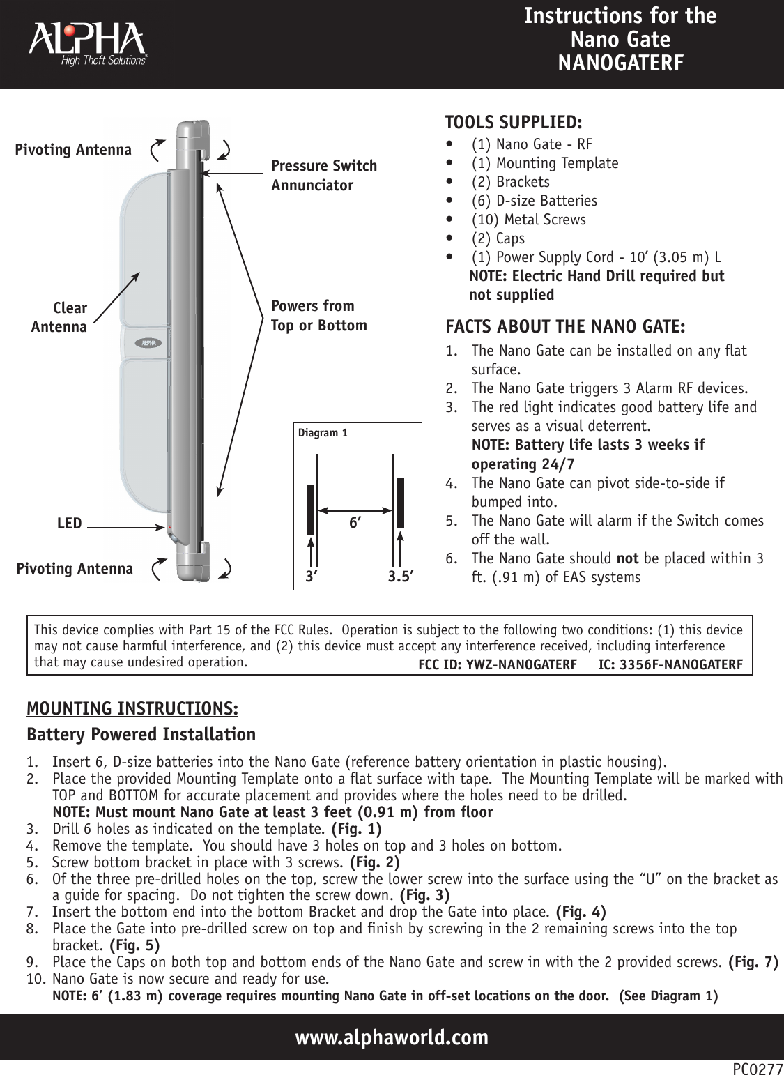
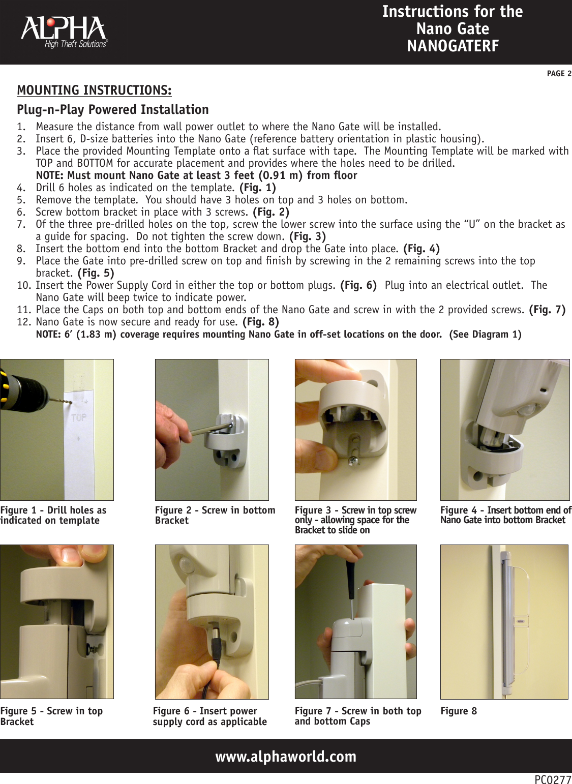
Checkpoint Systems NANOGATERF Security tags operating at 8.2 MHz User Manual Installation Guide

Alpha - High Theft Solutions, A Division of Checkpoint Systems, Inc. Security tags operating at 8.2 MHz Installation Guide

Installation Guide

www.alphaworld.comInstructions for the Nano Gate NANOGATERF1.  The Nano Gate can be installed on any at surface.2.  The Nano Gate triggers 3 Alarm RF devices.3.  The red light indicates good battery life and serves as a visual deterrent. NOTE: Battery life lasts 3 weeks if operating 24/74.  The Nano Gate can pivot side-to-side if bumped into.5.  The Nano Gate will alarm if the Switch comes off the wall.6.  The Nano Gate should not be placed within 3 ft. (.91 m) of EAS systemsFACTS ABOUT THE NANO GATE:•  (1) Nano Gate - RF•  (1) Mounting Template•  (2) Brackets•  (6) D-size Batteries•  (10) Metal Screws•  (2) Caps•  (1) Power Supply Cord - 10’ (3.05 m) L     NOTE: Electric Hand Drill required but       not suppliedTOOLS SUPPLIED:PC0277Pivoting AntennaClear AntennaLEDPressure Switch AnnunciatorPowers from Top or Bottom1.  Insert 6, D-size batteries into the Nano Gate (reference battery orientation in plastic housing).2.  Place the provided Mounting Template onto a at surface with tape.  The Mounting Template will be marked with TOP and BOTTOM for accurate placement and provides where the holes need to be drilled. NOTE: Must mount Nano Gate at least 3 feet (0.91 m) from oor3.  Drill 6 holes as indicated on the template. (Fig. 1)4.  Remove the template.  You should have 3 holes on top and 3 holes on bottom.5.  Screw bottom bracket in place with 3 screws. (Fig. 2)6.  Of the three pre-drilled holes on the top, screw the lower screw into the surface using the “U” on the bracket as a guide for spacing.  Do not tighten the screw down. (Fig. 3)7.  Insert the bottom end into the bottom Bracket and drop the Gate into place. (Fig. 4)8.  Place the Gate into pre-drilled screw on top and nish by screwing in the 2 remaining screws into the top bracket. (Fig. 5)9.  Place the Caps on both top and bottom ends of the Nano Gate and screw in with the 2 provided screws. (Fig. 7)10. Nano Gate is now secure and ready for use. NOTE: 6’ (1.83 m) coverage requires mounting Nano Gate in off-set locations on the door.  (See Diagram 1)MOUNTING INSTRUCTIONS:Battery Powered Installation6’Diagram 13.5’3’Pivoting AntennaThis device complies with Part 15 of the FCC Rules.  Operation is subject to the following two conditions: (1) this device may not cause harmful interference, and (2) this device must accept any interference received, including interference that may cause undesired operation. FCC ID: YWZ-NANOGATERF     IC: 3356F-NANOGATERF
www.alphaworld.comInstructions for the Nano Gate NANOGATERFMOUNTING INSTRUCTIONS:Plug-n-Play Powered InstallationPC02771.  Measure the distance from wall power outlet to where the Nano Gate will be installed.2.  Insert 6, D-size batteries into the Nano Gate (reference battery orientation in plastic housing).3.  Place the provided Mounting Template onto a at surface with tape.  The Mounting Template will be marked with TOP and BOTTOM for accurate placement and provides where the holes need to be drilled. NOTE: Must mount Nano Gate at least 3 feet (0.91 m) from oor4.  Drill 6 holes as indicated on the template. (Fig. 1)5.  Remove the template.  You should have 3 holes on top and 3 holes on bottom.6.  Screw bottom bracket in place with 3 screws. (Fig. 2)7.  Of the three pre-drilled holes on the top, screw the lower screw into the surface using the “U” on the bracket as a guide for spacing.  Do not tighten the screw down. (Fig. 3)8.  Insert the bottom end into the bottom Bracket and drop the Gate into place. (Fig. 4)9.  Place the Gate into pre-drilled screw on top and nish by screwing in the 2 remaining screws into the top bracket. (Fig. 5)10. Insert the Power Supply Cord in either the top or bottom plugs. (Fig. 6)  Plug into an electrical outlet.  The Nano Gate will beep twice to indicate power.11. Place the Caps on both top and bottom ends of the Nano Gate and screw in with the 2 provided screws. (Fig. 7)12. Nano Gate is now secure and ready for use. (Fig. 8)NOTE: 6’ (1.83 m) coverage requires mounting Nano Gate in off-set locations on the door.  (See Diagram 1)PAGE 2Figure 1 - Drill holes as indicated on template Figure 2 - Screw in bottom Bracket Figure 3 - Screw in top screw only - allowing space for the Bracket to slide onFigure 4 - Insert bottom end of Nano Gate into bottom BracketFigure 5 - Screw in top Bracket  Figure 6 - Insert power supply cord as applicable Figure 7 - Screw in both top and bottom Caps Figure 8

Navigation menu