Cheng Uei Precision Industry 20100000 802.11g/b Mini PCI User Manual
Cheng Uei Precision Industry Co., Ltd. 802.11g/b Mini PCI
UserManual.wiki
>
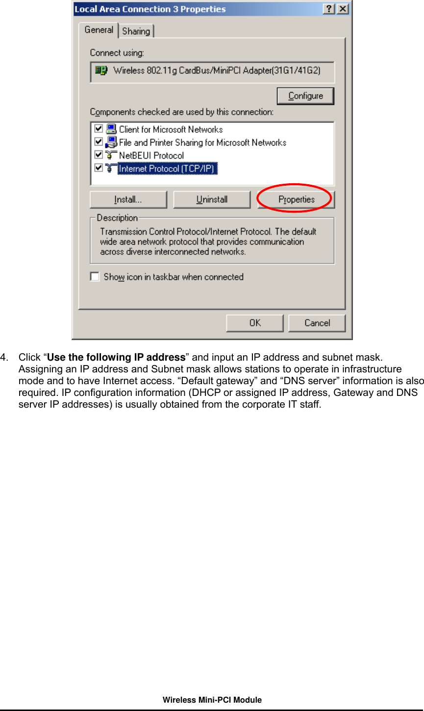
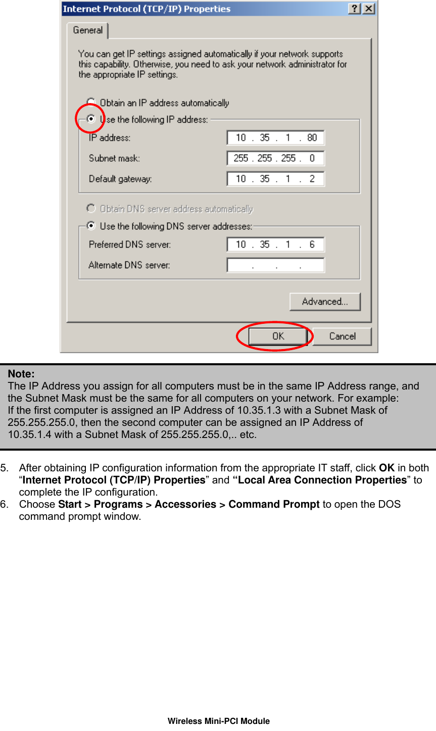
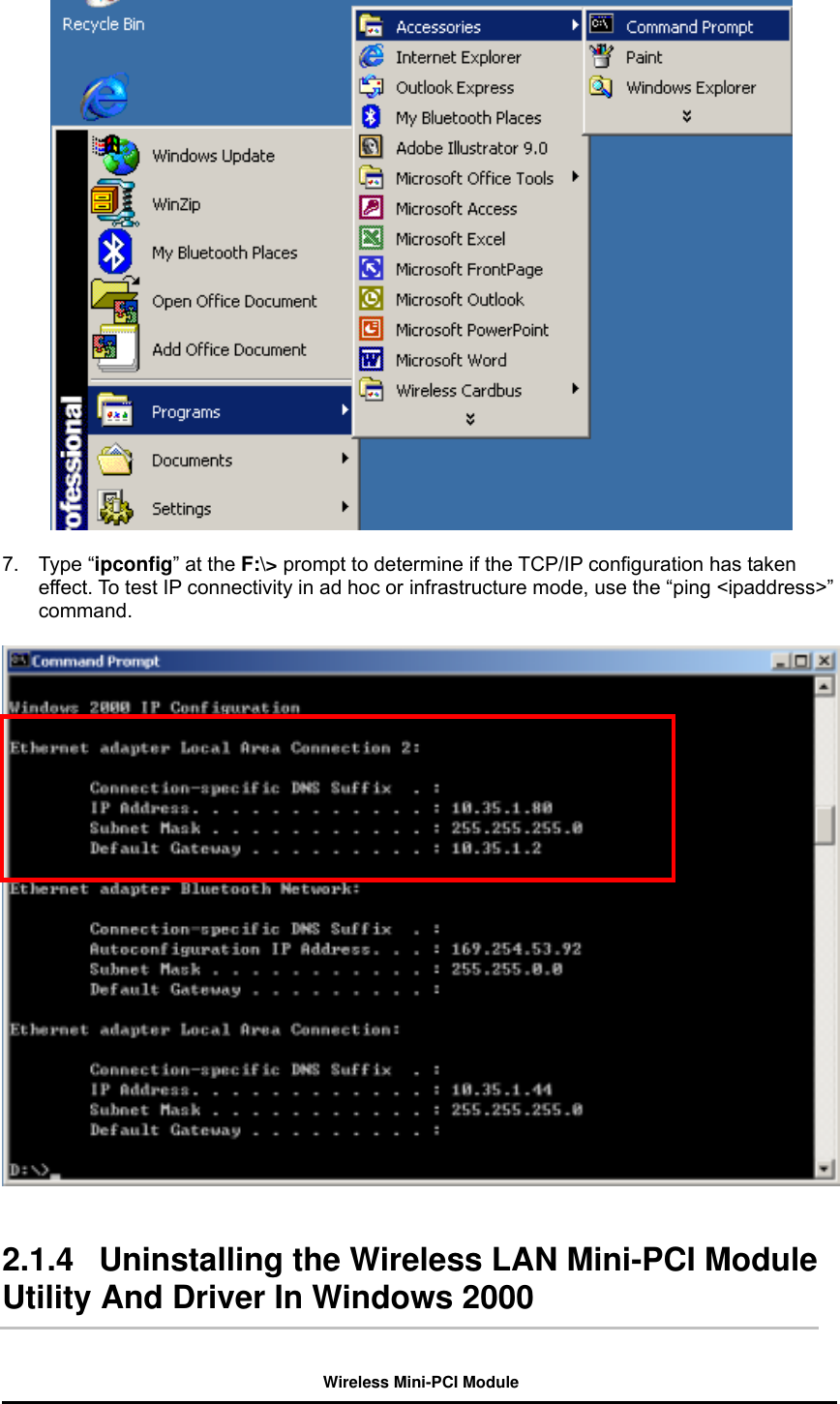
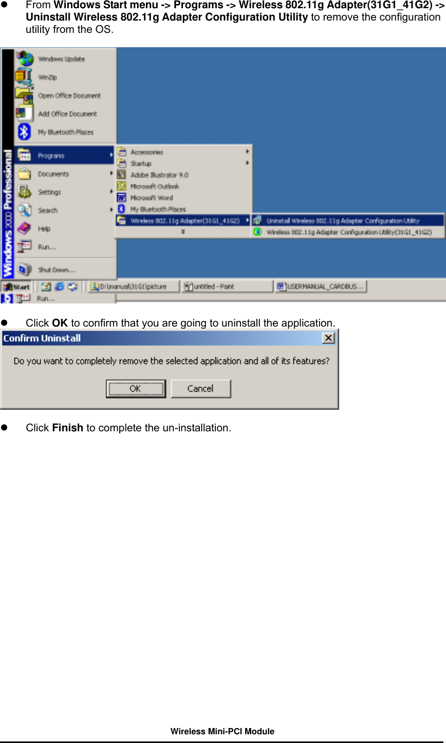
Cheng Uei Precision Industry
>
20100000 User Manual
User Manual
Navigation menu
Upload a User Manual
Namespaces
Wiki Guide
HTML
PDF
Info
Views
User Manual
Discussion / Help
Navigation