Cheng Uei Precision Industry 20100000 802.11g/b Mini PCI User Manual
Cheng Uei Precision Industry Co., Ltd. 802.11g/b Mini PCI
User Manual
IEEE 802.11 g 54Mbps
Wireless LAN Mini-PCI Module
User’s Manual

Wireless Mini-PCI Module
Table of Content
CHAPTER1 INTRODUCTION................................................................................................... 6
1.1 SYSTEM REQUIREMENT .............................................................................................. 6
1.2 WIRELESS LAN MINI-PCI MODULE FEATURES............................................................. 6
CHAPTER2 INSTALLATION AND CONFIGURATION PROCEDURES................................. 8
2.1 INSTALLATION PROCEDURES IN WINDOWS2000 ........................................................... 8
2.1.1 Installing the Wireless LAN Mini-PCI Module Driver and Configuration
Utility 8
2.1.2 VERIFYING YOUR INSTALLATION IN WINDOWS2000 ................................................ 12
2.1.3 TCP/IP SETUP IN WINDOWS 2000........................................................................ 15
2.1.4 Uninstalling the Wireless LAN Mini-PCI Module Utility And Driver In
Windows 2000................................................................................................................. 18
2. 2 INSTALLATION PROCEDURES IN WINDOWS XP ....................................................... 20
2. 2.1 Installing the Wireless LAN Mini-PCI Module Driver and Utility................ 20
2.2.2 Verifying Your Installation In Windows XP..................................................... 25
2.2.3 Uninstalling the Wireless LAN Mini-PCI Module Utility And Driver In Windows
XP 28
CHAPTER3 WIRELESS ADAPTER UTILITY ........................................................................ 30
3.1 WIRELESS ADAPTER UTILITY ..................................................................................... 30
3.2 WIRELESS LAN CARD UTILITY – LINK INFO TAB ......................................................... 30
3.3 WIRELESS LAN ADAPTER UTILITY – CONFIGURATION TAB .......................................... 32
3.3.1 Configuration Tab – Connection .................................................................... 33
3.3.2 Configuration Tab – Encryption ..................................................................... 35
3.3.3 Configuration Tab – Advanced ...................................................................... 37
3.4 WIRELESS LAN ADAPTER UTILITY – SITE SURVEY TAB...................................................... 40
3.5 WIRELESS LAN CARD UTILITY – STATISTICS TAB .............................................................. 40
3.6 WIRELESS LAN ADAPTER UTILITY – DEVICE INFO TAB ...................................................... 41
CHAPTER4 USING WINXP BUILT-IN WIRELESS NETWORK CONFIGURATION UTILITY
................................................................................................................................................. 43
4.1 OPEN THE LOCAL AREA CONNECTION DIALOG BOX............................................................. 43
4.2 INFRASTRUCTURE MODE SETUP PROCEDURE ................................................................... 44
4.3 AD-HOC MODE SETUP PROCEDURE.................................................................................. 47
4.4 NETWORK OPERATING MODE SELECTION ......................................................................... 50

Wireless Mini-PCI Module
Regulatory Compliance
FCC Warning
This device complies with Part 15 of the FCC Rules.
Operation is subject to the following two conditions: (1) this device may not cause harmful
interference, and (2) this device must accept any interference received, including interference
that may cause undesired operation.
This equipment has been tested and found to comply with the limits for a Class B digital device,
pursuant to part 15 of the FCC Rules. These limits are designed to provide reasonable
protection against harmful interference in a residential installation.
This equipment generates, uses and can radiate radio frequency energy and, if not installed
and used in accordance with the instructions, may cause harmful interference to radio
communications. However, there is no guarantee that interference will not occur in a particular
installation. If this equipment does cause harmful interference to radio or television reception,
which can be determined by turning the equipment off and on, the user is encouraged to try to
correct the interference by one or more of the following measures:
Reorient or relocate the receiving antenna.
Increase the separation between the equipment and receiver.
Connect the equipment into an outlet on a circuit different from that to which the receiver
is connected.
Consult the dealer or an experienced radio/TV technician for help.
Changes or modifications not expressly approved by the party responsible for
compliance could void your authority to operate the equipment.
1) To comply with FCC RF exposure compliance requirements, a separation distance of at
least 20 cm must be maintained between the antenna of this device and all persons.
2) This transmitter must not be co-located or operating in conjunction with any other antenna
or transmitter.
This device is intended only for OEM integrators under the following conditions:
1) The antenna must be installed such that 20 cm is maintained between the antenna and
users, and
2) The transmitter module may not be co-located with any other transmitter or antenna.
As long as 2 conditions above are met, further transmitter test will not be required. However,
the
OEM integrator is still responsible for testing their end-product for any additional compliance
requirements required with this module installed (for example, digital device emissions, PC
peripheral requirements, etc.).
IMPORTANT NOTE: In the event that these conditions can not be met (for example certain
laptop
configurations or co-location with another transmitter), then the FCC authorization is no longer
considered valid and the FCC ID can not be used on the final product. In these circumstances,
the
OEM integrator will be responsible for re-evaluating the end product (including the transmitter)
and
obtaining a separate FCC authorization.
End Product Labeling
This transmitter module is authorized only for use in device where the antenna may be
installed
such that 20 cm may be maintained between the antenna and users (for example access
points,

Wireless Mini-PCI Module
routers, wireless ADSL modems, and similar equipment). The final end product must be
labeled in
a visible area with the following: "Contains TX FCC ID: FCC IDGQVZ20100000".
Manual Information for End Users
The end user must not have manual instructions to remove or install the device.
The user manual for end users must include the following information in a prominent location:
"IMPORTANT NOTE: To comply with FCC RF exposure compliance requirements, the
antenna
used for this transmitter must be installed to provide a separation distance of at least 20 cm
from all
persons and must not be co-located or operating in conjunction with any other antenna or
transmitter."

Wireless Mini-PCI Module
Chapter1
Introduction
This 802.11g Mini-PCI module offers high-speed wireless connection up to 54Mbps. It shares
the same 2.4GHz radio band with 80.11b products so it can interoperate with existing 802.11b
networking products. With the wireless network adapter installed, you can connect to
wireless-B (802.11b) and Wireless-G (draft 802.11g) networks.
With this module and appropriate drivers and utility installed, you can transform your wired
device into wireless station easily and thus access your wireless and wired network quickly.
Fully compliant to Wired Equivalent Privacy (WEP) with 64-bit and 128-bit encryption, so it can
offer a reliable and secure wireless communication.
This wireless network adapter provides a fast and convenient way to connect your laptop or
desktop to a wireless station or as an integral part of a wired local area network with a wireless
network segment. You can configure this network card in Ad-Hoc mode (without an access
point) or Infrastructure mode (with an access point).
1.1 System Requirement
To properly use your wireless Mini-PCI module, please make sure that your laptop or desktop
meets the following minimum system requirements:
The laptop or desktop must have one of the operating systems, i.e: MS Windows 98SE,
ME, 2000 and WinXP
CD-ROM drive
Desktop PC: Mini-PCI slot in case of desktop PC
Laptop: Mini-PCI slot
1.2 Wireless LAN Mini-PCI Module Features
This wireless Mini-PCI module offers compliance with IEEE 802.11g standard so it allows
communicate with other manufacturers’ wireless devices that support this standard. The
followings are the main distinguishing features of this wireless adapter.
Compatible with IEEE 802.11g high rate standard to provide wireless speeds of
54Mbps data rate with OFDM modulation.
Backward compatible with IEEE 802.11b high rate standard to provide wireless
speeds of 11Mbps data rate with CCK modulation
Dynamic date rate scaling at 54, 48, 36, 24, 18, 12, 9 Mbps in OFDM mode
Dynamic date rate scaling at 11, 5.5 Mbps in CCK mode; 2 and 1Mbps in DQPSK
and DBPSK mode.
Maximum reliability, throughput and connectivity with automatic fallback, auto-switch
between OFDM and CCK.
Supports wireless data encryption with 128-bit WEP and WPA standard for security
Drivers support Windows 98SE, 2000, ME, XP

Wireless Mini-PCI Module
Simple user setup & diagnostics utilities
Type approval compliant with FCC Part 15.247 for US, EN 300-328 for Europe, and
RCR STD-33A and ARIB STD-T66 for Japan

Wireless Mini-PCI Module
Chapter2
Installation and
Configuration Procedures
2.1 Installation Procedures In Windows2000
The Wireless LAN Mini-PCI Module Windows driver ships with the Wireless Adapter
Configuration Utility.
Before you start:
Obtain this Utility CD.
Turn off your notebook or computer. Insert the Mini-PCI module into the slot on your
computer’s motherboard.
2.1.1 Installing the Wireless LAN Mini-PCI Module
Driver and Configuration Utility
Turn on your computer or notebook, there will be a hardware found screen. Click Cancel from
the Hardware Found Wizard.
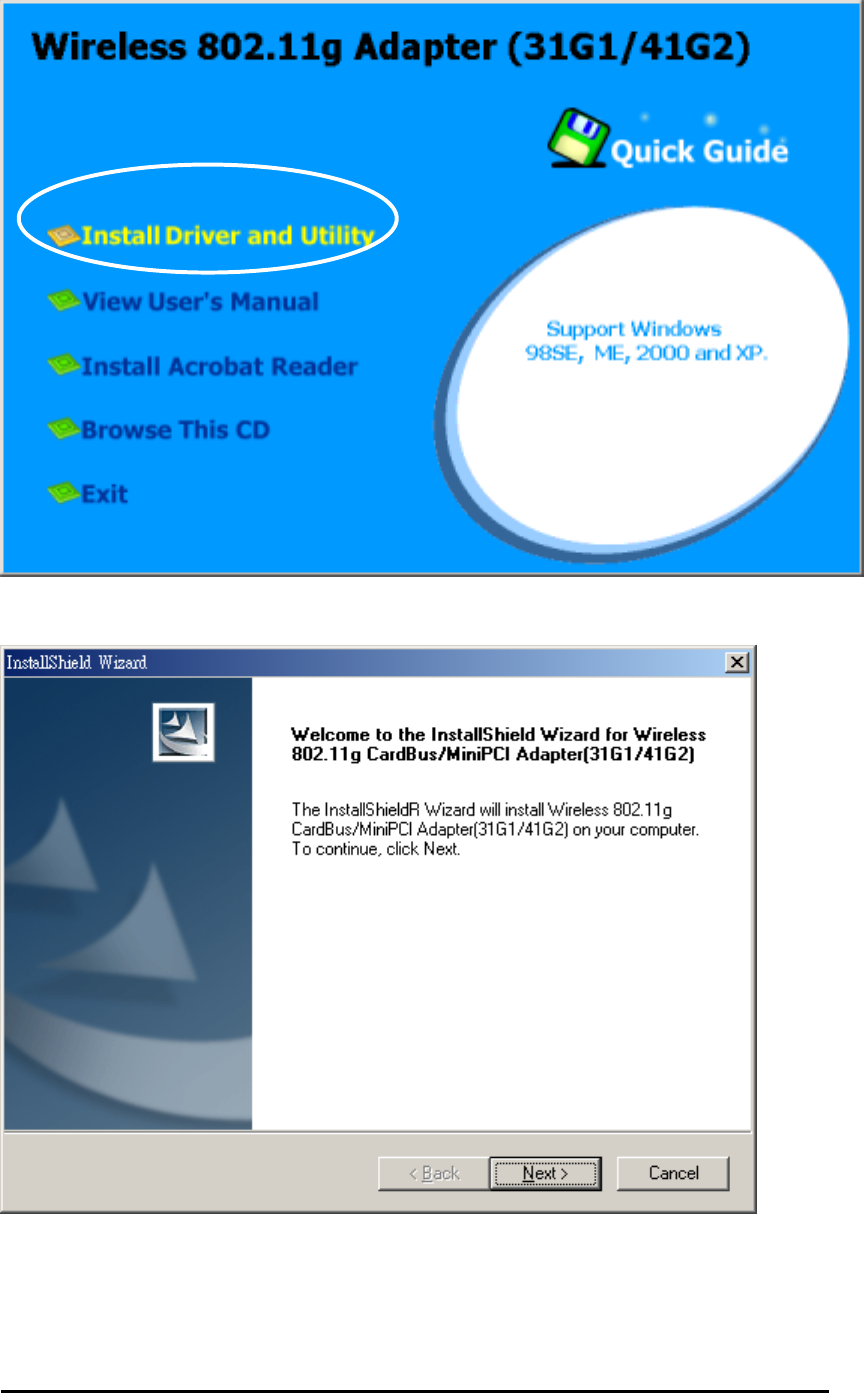
Close any open programs and insert the utility CD into your CD-ROM Drive. The Autorun
function will automatically start and the following main screen will be pop-up. Double-click on
the Install Driver and Utility item to start the software installation. (If the Autorun function
does not automatically start, please open the Installation CD to find the Setup.exe file and
double click the Setup.exe icon to continue.) Click the “View User’s Manual” to view the user’s
manual and click “Install Acrobat Reader” to install software to view the user’s manual. If you
don’t want to install right now you can click “Browse This CD” to view the CD files and click
Exit to close the main screen.
Wireless Mini-PCI Module
1. The InstallShield Wizard is preparing to install the configuration utility and drivers. Click
Next.
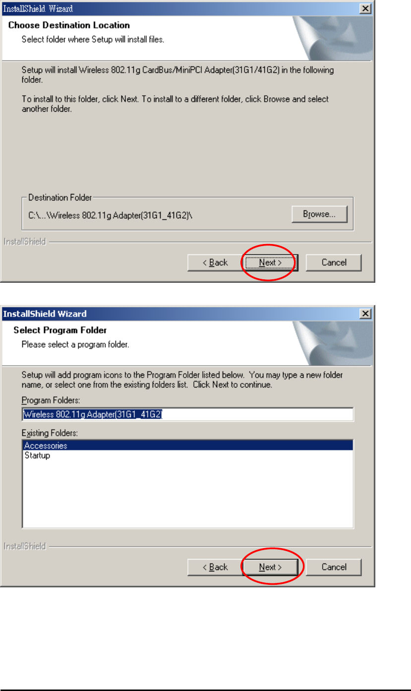
2. In the Destination Folder screen you are asked to confirm the Destination Folder for the
application software. If you would like, you may change the destination folder to another
location as the directory. Click Next.
Wireless Mini-PCI Module
3. Select a program folder and click Next.
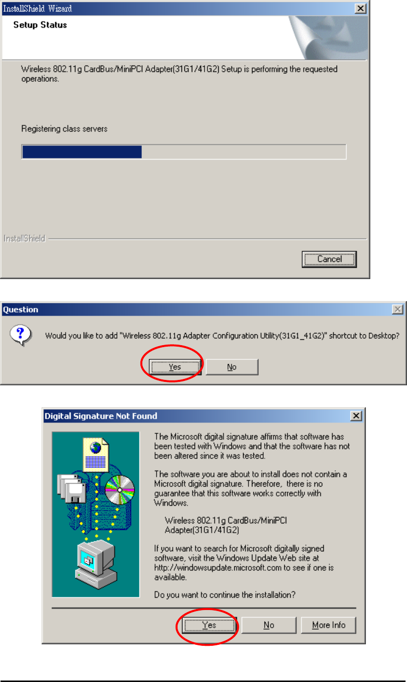
4. The InstallShield Wizard is installing utility.
Wireless Mini-PCI Module
5. Click YES button, if you want to create a shortcut icon on your Windows desktop.
6. Click Yes from the Digital Signature dialog box. A Microsoft digital signature is not
required at this moment.
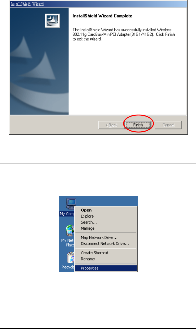
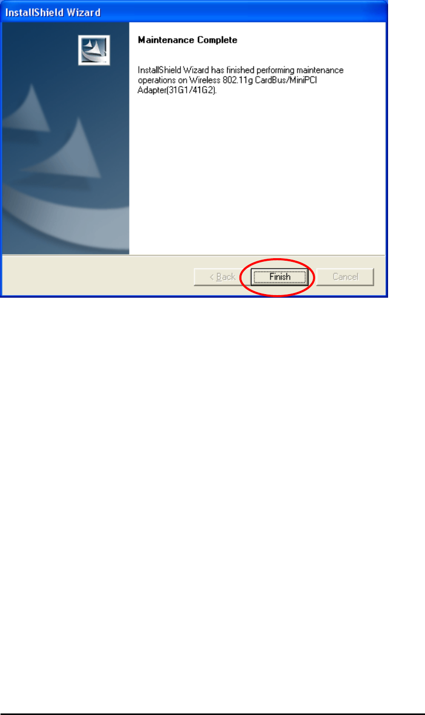
7. Click Finish to finish the driver and utility installation.
Wireless Mini-PCI Module
The wireless adapter utility will launch automatically and the utility icon will reside on the
system tray.
2.1.2 Verifying Your Installation In Windows2000
Verify the driver has installed successful
If you want to check if the driver’s installation is successful or not, follow the next steps.
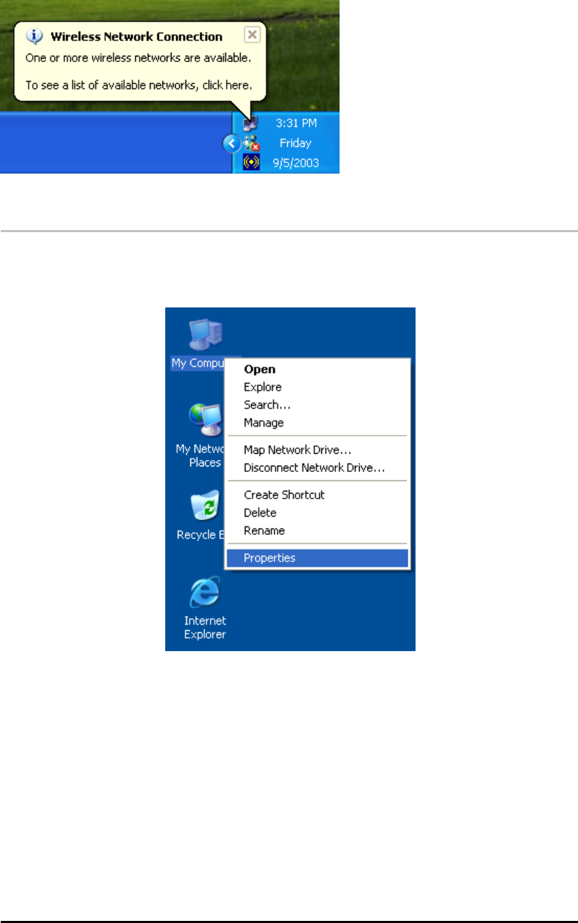
1. Right-click mouse button on the My Computer icon on your Windows desktop, and
highlight Properties from the pop-up menu.
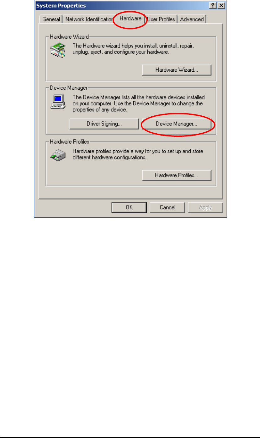
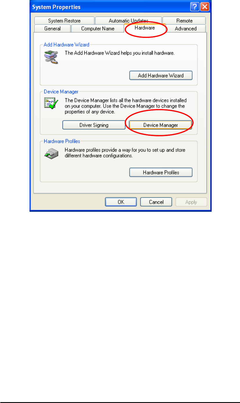
2. The System Properties screen will be pop-up. Under Hardware tab, click Device
Manager….
Wireless Mini-PCI Module
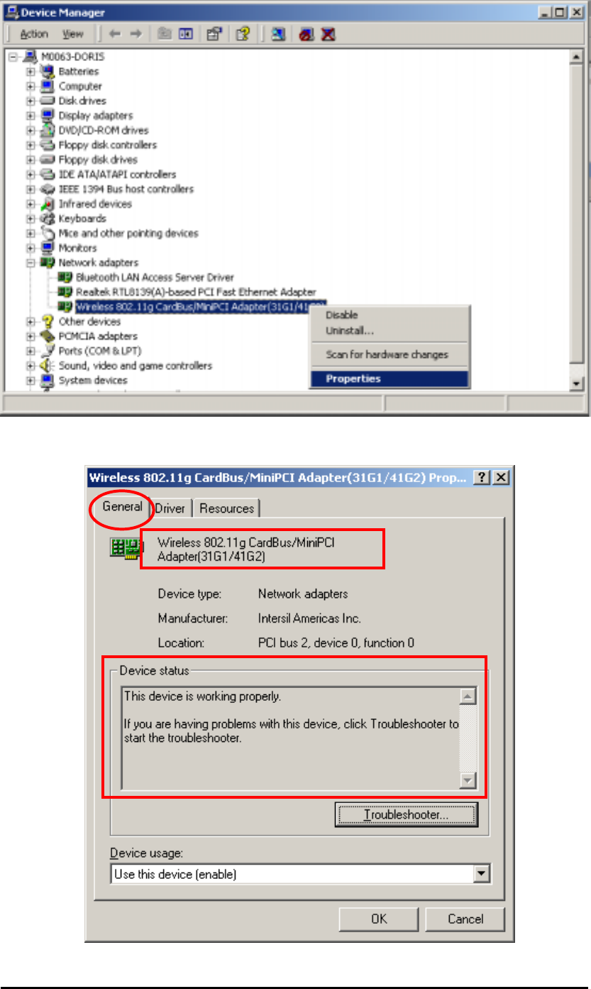
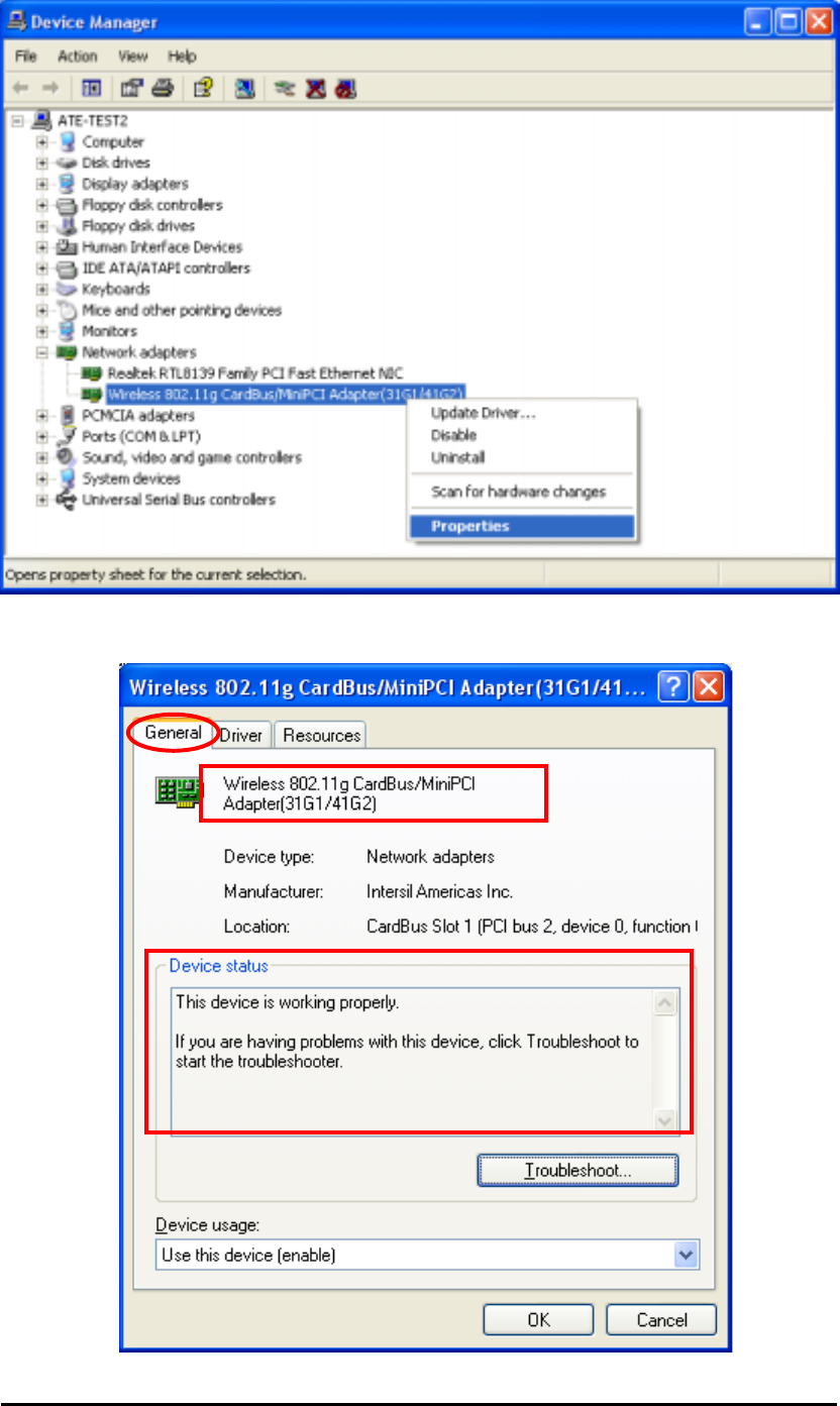
3. After clicking Device Manager…, the following screen will be shown. Click on the +
symbol in front of “Network adapters” and see if an item labeled Wireless 802.11g
CardBus/MiniPCI Adapter (34G1/41G2) is visible. If you don’t see the item below the
network adapter icon but a”?” or “!” symbol is displayed, it means that the driver installation
was unsuccessful. Highlight “Wireless 802.11g CardBus/MiniPCI Adapter (34G1/41G2)”,
right-click mouse button and select “Properties”.
Wireless Mini-PCI Module
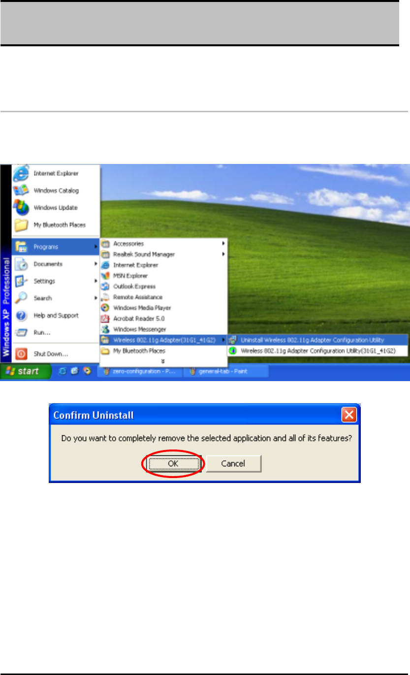
4. Click the General tab, if the Device Status field reports that “This device is working
properly”, it means that the driver has been installed successfully.
Wireless Mini-PCI Module
2.1.3 TCP/IP Setup In Windows 2000
Configuring the TCP/IP setup allows the desktop or laptop equipped with a wireless LAN
adapter to operate in infrastructure mode and to have the Internet access. So after the
configuration utility and WLAN adapter driver are installed, the TCP/IP address for the wireless
LAN card must be configured.
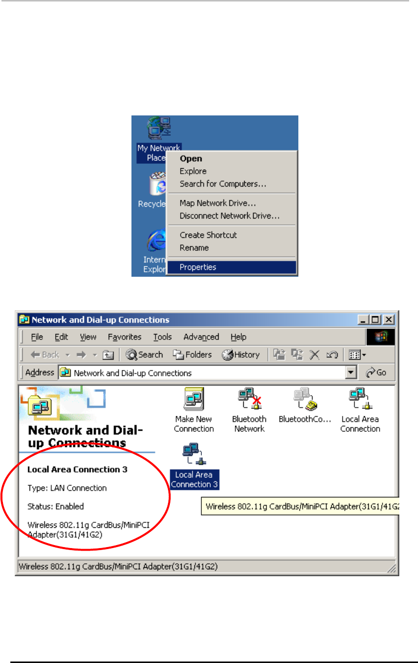
1. Right-click mouse button on the My Network Places and highlight Properties from the
pop-up menu.
2. Find the “Local Area Connection” that is associated with the wireless LAN Mini-PCI
module. Right-click mouse button on the connection and click Properties.
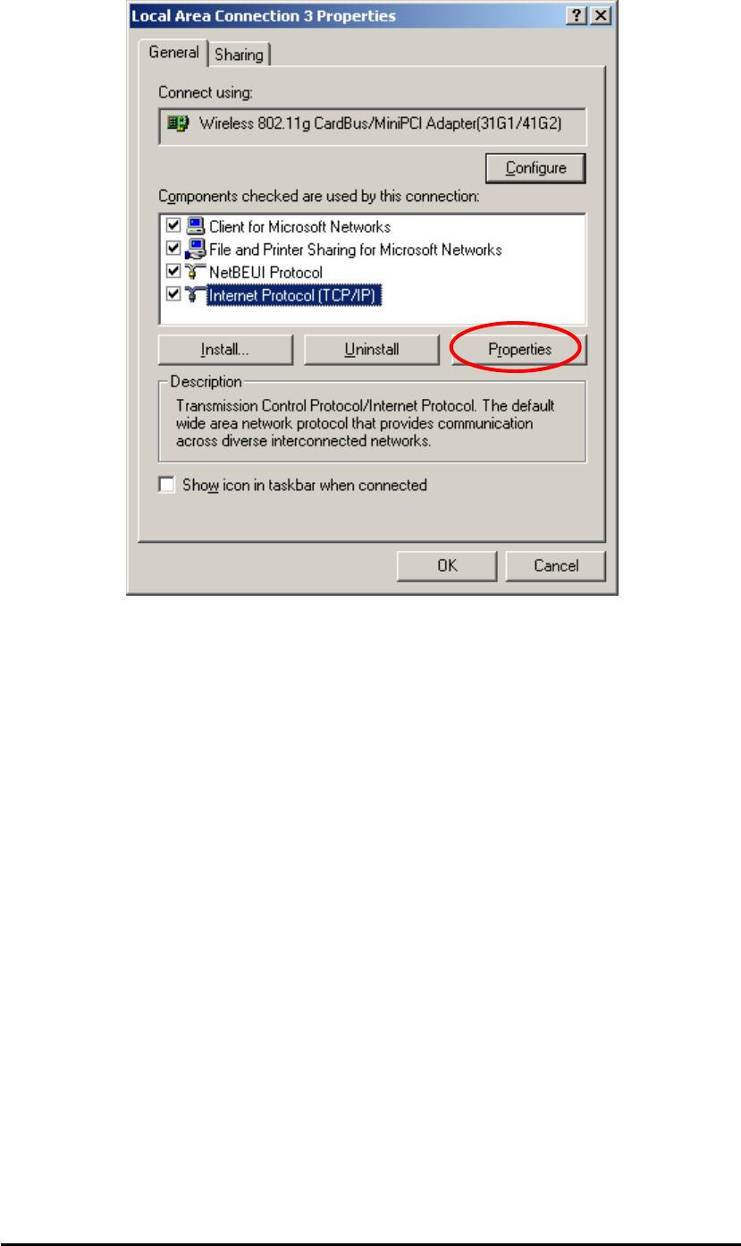
3. Select “Internet Protocol (TCP/IP)” and click Properties.
Wireless Mini-PCI Module
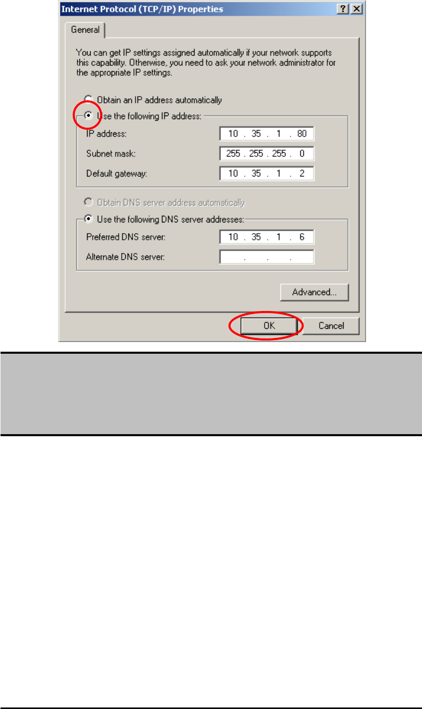
4. Click “Use the following IP address” and input an IP address and subnet mask.
Assigning an IP address and Subnet mask allows stations to operate in infrastructure
mode and to have Internet access. “Default gateway” and “DNS server” information is also
required. IP configuration information (DHCP or assigned IP address, Gateway and DNS
server IP addresses) is usually obtained from the corporate IT staff.
Wireless Mini-PCI Module
5. After obtaining IP configuration information from the appropriate IT staff, click OK in both
“Internet Protocol (TCP/IP) Properties” and “Local Area Connection Properties” to
complete the IP configuration.
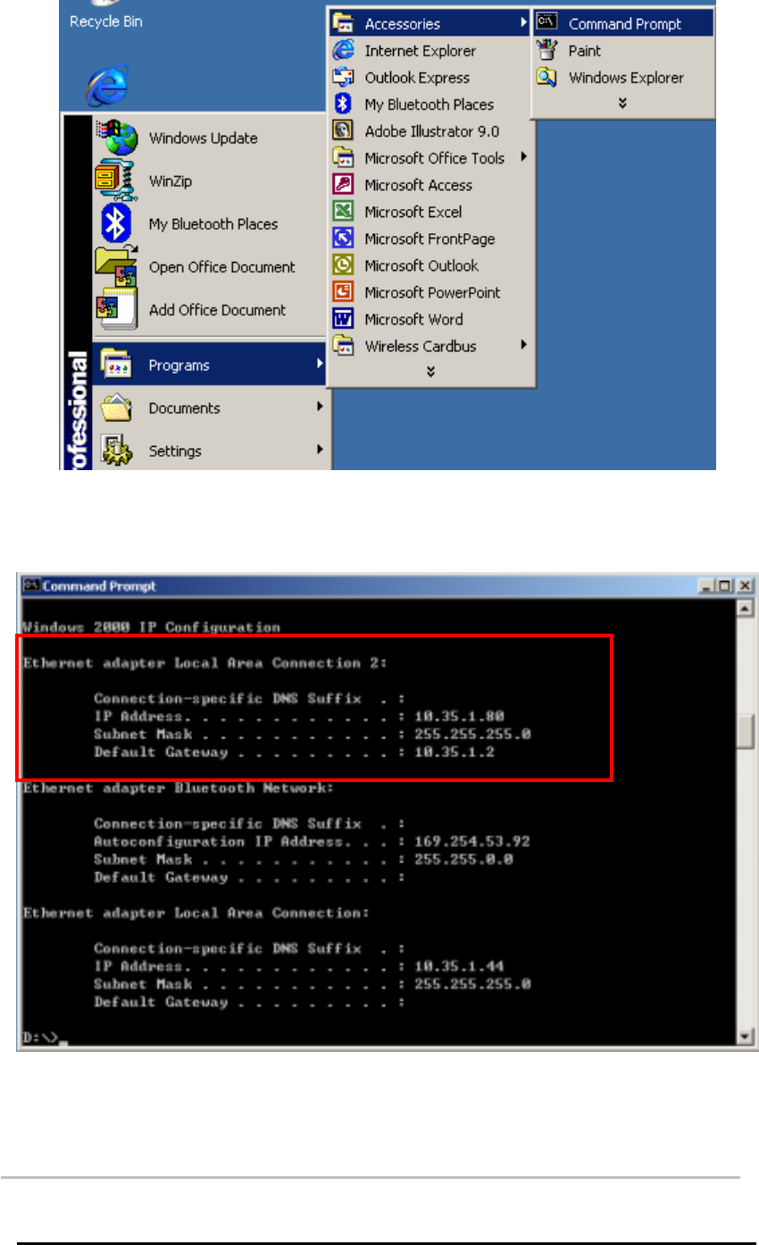
6. Choose Start > Programs > Accessories > Command Prompt to open the DOS
command prompt window.
Note:
The IP Address you assign for all computers must be in the same IP Address range, and
the Subnet Mask must be the same for all computers on your network. For example:
If the first computer is assigned an IP Address of 10.35.1.3 with a Subnet Mask of
255.255.255.0, then the second computer can be assigned an IP Address of
10.35.1.4 with a Subnet Mask of 255.255.255.0,.. etc.
Wireless Mini-PCI Module
7. Type “ipconfig” at the F:\> prompt to determine if the TCP/IP configuration has taken
effect. To test IP connectivity in ad hoc or infrastructure mode, use the “ping <ipaddress>”
command.
2.1.4 Uninstalling the Wireless LAN Mini-PCI Module
Utility And Driver In Windows 2000
Wireless Mini-PCI Module
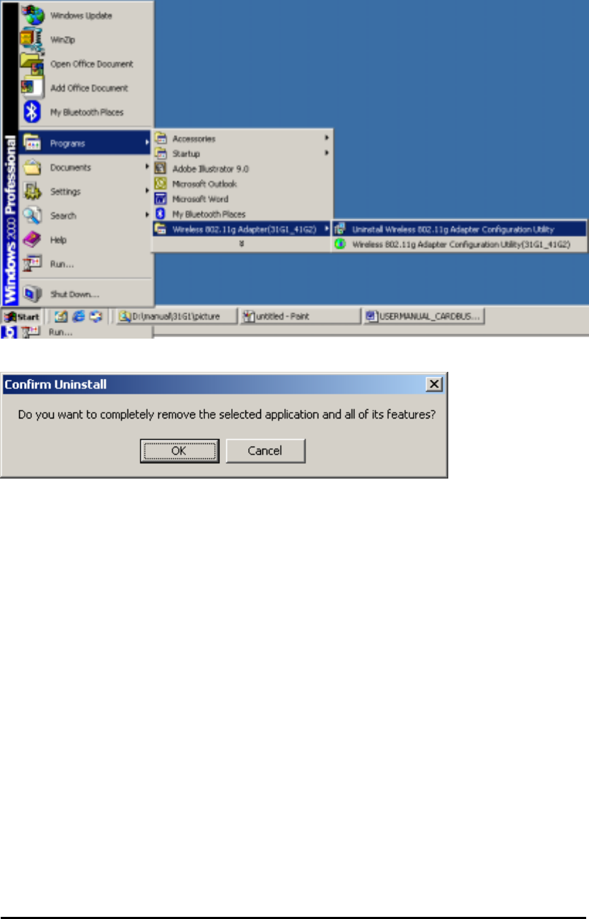
From Windows Start menu -> Programs -> Wireless 802.11g Adapter(31G1_41G2) ->
Uninstall Wireless 802.11g Adapter Configuration Utility to remove the configuration
utility from the OS.
Click OK to confirm that you are going to uninstall the application.
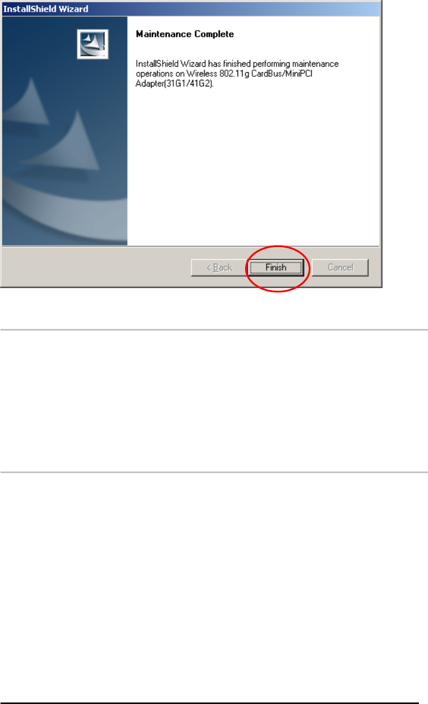
Click Finish to complete the un-installation.
Wireless Mini-PCI Module
2. 2 Installation Procedures In Windows XP
The Windows XP provides a built-in wireless LAN configuration application. No matter you
want to use the Windows Zero Configuration utility or the utility we provide, you still have to
click the Install Driver and Utility icon below to install the necessary drivers and the utility.
Before you start:
Obtain this Utility CD.
Turn off your notebook or computer. Insert the mini-PCI module into the slot on your
computer’s motherboard.
2. 2.1 Installing the Wireless LAN Mini-PCI Module
Driver and Utility
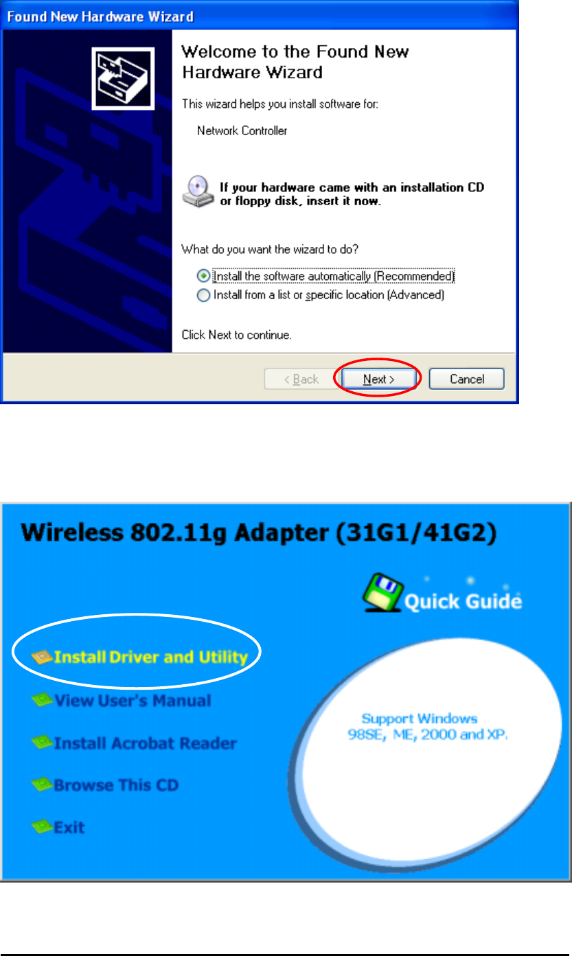
Turn on your computer or notebook. Click Cancel from the Found New Hardware Wizard.
Wireless Mini-PCI Module
Close any open programs and insert the utility CD into your CD-ROM Drive. The Autorun
function will automatically start and the following main screen will be pop-up. Double-click on
the Install Driver and Utility item to start the software installation. (If the Autorun function
does not automatically start, please open the Installation CD to find the Setup.exe file and
double click the Setup.exe icon to continue.)
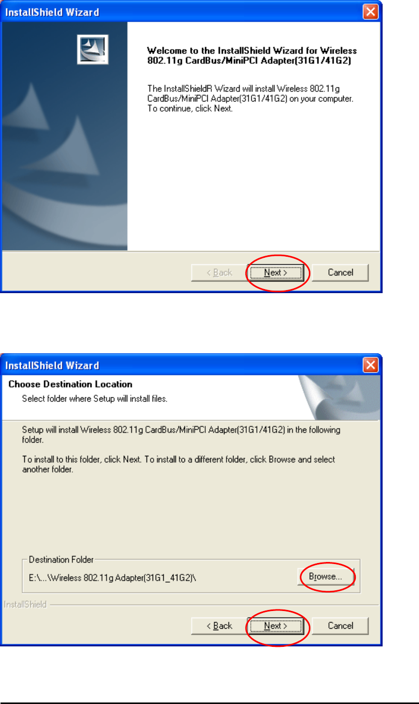
The InstallShield Wizard is preparing to install the configuration utility and driver.
Wireless Mini-PCI Module
In the Destination Folder screen you are asked to confirm the Destination Folder for the
application software. If you would like, you may change the destination folder to another
location as the directory. Click Next.
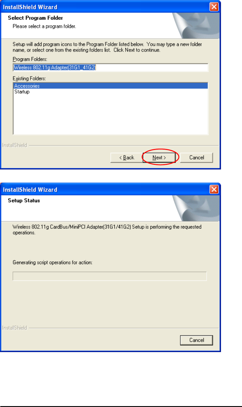
Select a program folder and click Next.
Wireless Mini-PCI Module
The InstallShield Wizard is installing utility.
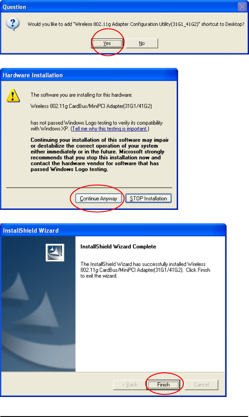
Click Yes if you want to create the shortcut on your Windows desktop.
Wireless Mini-PCI Module
Click Continue Anyway to continue the installation.
Click Finish to complete the utility installation.
Wireless Mini-PCI Module
The bubble message on the system tray indicates that the network adapter is ready to
use. You can click on the bubble message and start to configure the network adapter.
2.2.2 Verifying Your Installation In Windows XP
To check if you have installed the driver successfully, please follow the following steps.
Right-click mouse button on the My computer icon on your windows desktop and select
Properties from the pop-up menu.
Under Hardware tab, click Device Manager.
Wireless Mini-PCI Module
Double-click Network adapters. Right-click mouse button on “Wireless 802.11g
CardBus/MiniPCI Adapter (31G1/41G2)” and select “Properties”.
Wireless Mini-PCI Module
Click the General tab, if the Device Status field reports that “This device is working
properly”, it means that the driver has been installed successfully.
Wireless Mini-PCI Module
2.2.3 Uninstalling the Wireless LAN Mini-PCI Module
Utility And Driver In Windows XP
From the Windows Start menu -> Programs -> Wireless 802.11g
Adapter(31G1_41G2) -> Uninstall Wireless 802.11g Adapter Configuration
Utility to remove the configuration utility.
Click OK to confirm that you are going to uninstall the utility.
Click Finish to complete the un-installation.
Note:
As for how to do TCP/IP setup in Windows XP, please refer to the TCP/IP setup
procedure in Windows 2000 section.
Wireless Mini-PCI Module
Wireless Mini-PCI Module
Chapter3
Wireless Adapter Utility
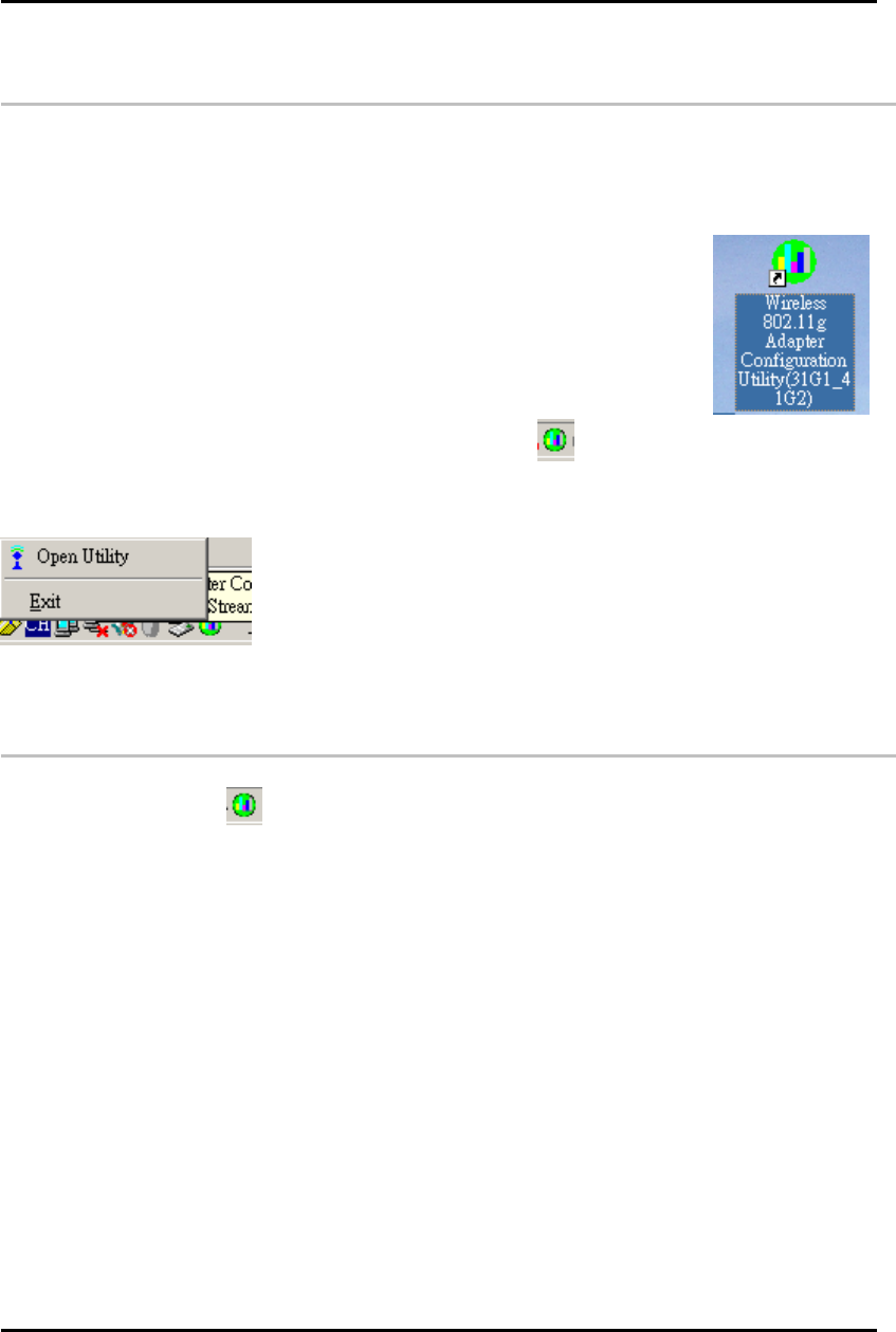
3.1 Wireless Adapter Utility
The user-friendly wireless adapter configuration Utility helps you to configure this WLAN
Mini-PCI module and monitor its connection status. You can change configuration parameters
while the adapter is active. You can open the utility for the utility from the Windows Start
menu -> Programs -> Wireless 802.11g Adapter (31G1_41G2) -> Wireless 802.11g
Adapter Configuration Utility (31G1_41G2) or double-click the utility icon
on your Windows desktop and there will be a WLAN icon resides on the system tray. This
WLAN utility icon will reside on the system tray when you reboot your PC. Double-click on this
icon and the wireless LAN adapter utility window will be pop-up on screen. Right-click mouse
button on the utility icon and you can select option from the pop-up menu.
Open Utility – Open the utility main window.
Exit – Close the Wireless Adapter utility and the icon will exit from the system tray.
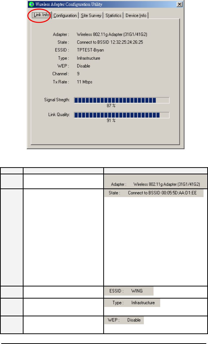
3.2 Wireless LAN Card Utility – Link Info Tab
Click WLAN Utility icon once and the wireless adapter Utility window will be shown on
screen displaying the related information of Link Info tab. From the Link Info Tab, you can
know the adapter’s name, get the adapter’s configuration and connection information. This
page is intended to provide the adapter’s information only so you can view the information
listed here but can’t change any item. You may change several parameters from the
Configuration Tab.
Wireless Mini-PCI Module
Link Info Tab
Item Description Figure
Adapter Displaying the name of the adapter.
State Displaying the working status of the
adapter.
Scanning:
Indicating the adapter is searching
other wireless devices in service
range.
Not Associated:
Indicating that the adapter is not
connected with any wireless device
yet.
Connect to BSSID:
xx:xx:xx:xx:xx:xx
Indicating the adapter is connected
with an access point or other
wireless LAN adapter and the
associated device’s MAC address is
displayed in the form of hex digits.
ESSID Indicating the ESSID of the
connected wireless device.
Type Indicating the current network type
the adapter uses. It could be Ad
hoc or Infrastructure.
WEP Indicating whether the connected
device enable WEP function or not.
Disable: It means that the
Wireless Mini-PCI Module
connected device doesn’t enable
WEP function.
Enable: It means that the
connected device uses WEP
function.
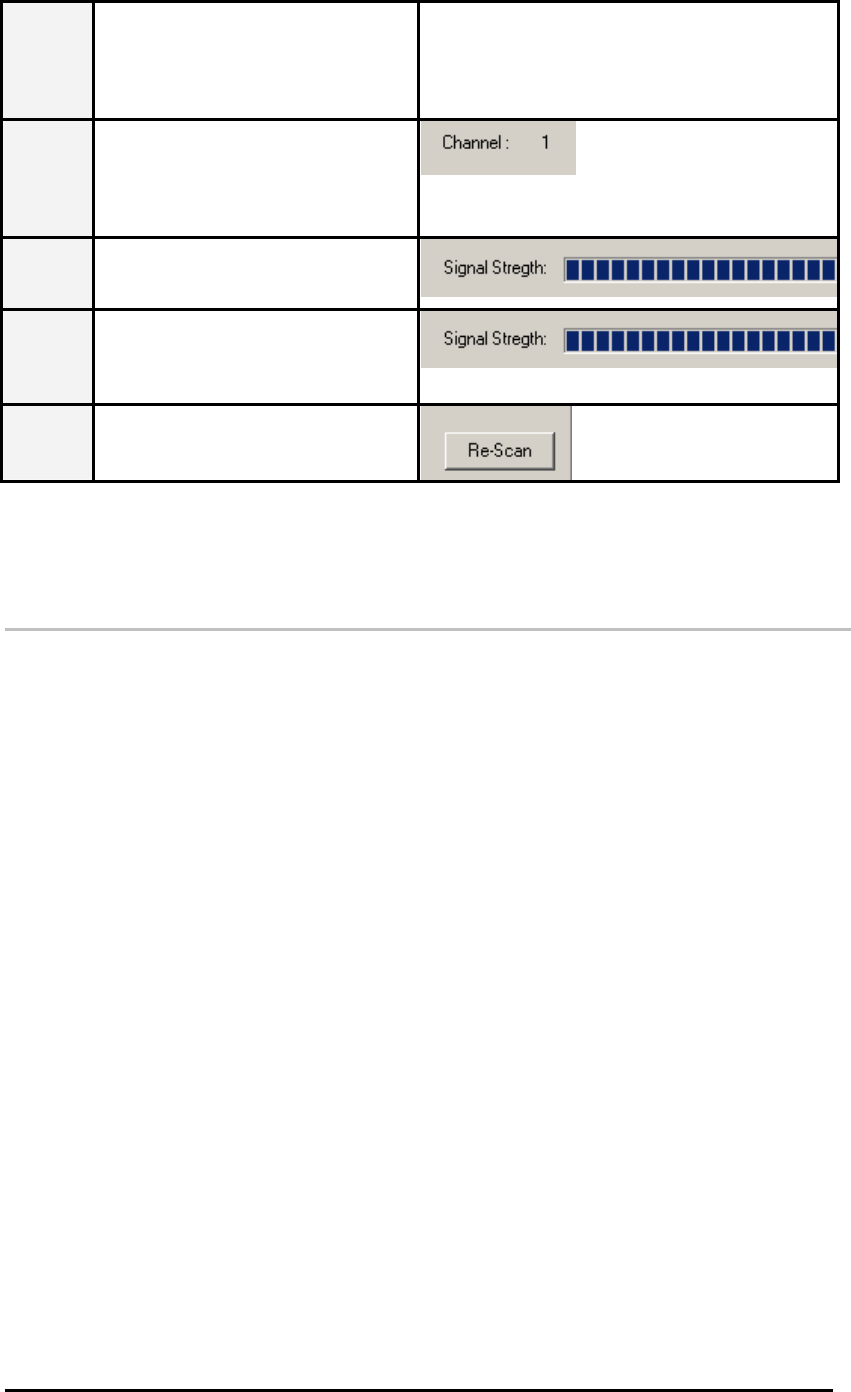
Channel In infrastructure mode, it indicates
the channel number the associated
access point uses. In
Ad hoc mode, it indicates the
channel number the adapter uses.
Signal
Strength The blue bar indicates the signal is
weak or strong. The longer the blue
bar is, the stronger the signal is.
Link
Quality The blue bar indicates the link
quality is good or bad. The longer
the blue bar is, the better link quality
is.
Re-Scan Click this button and then the card
will start to re-scan other wireless
devices in service range.
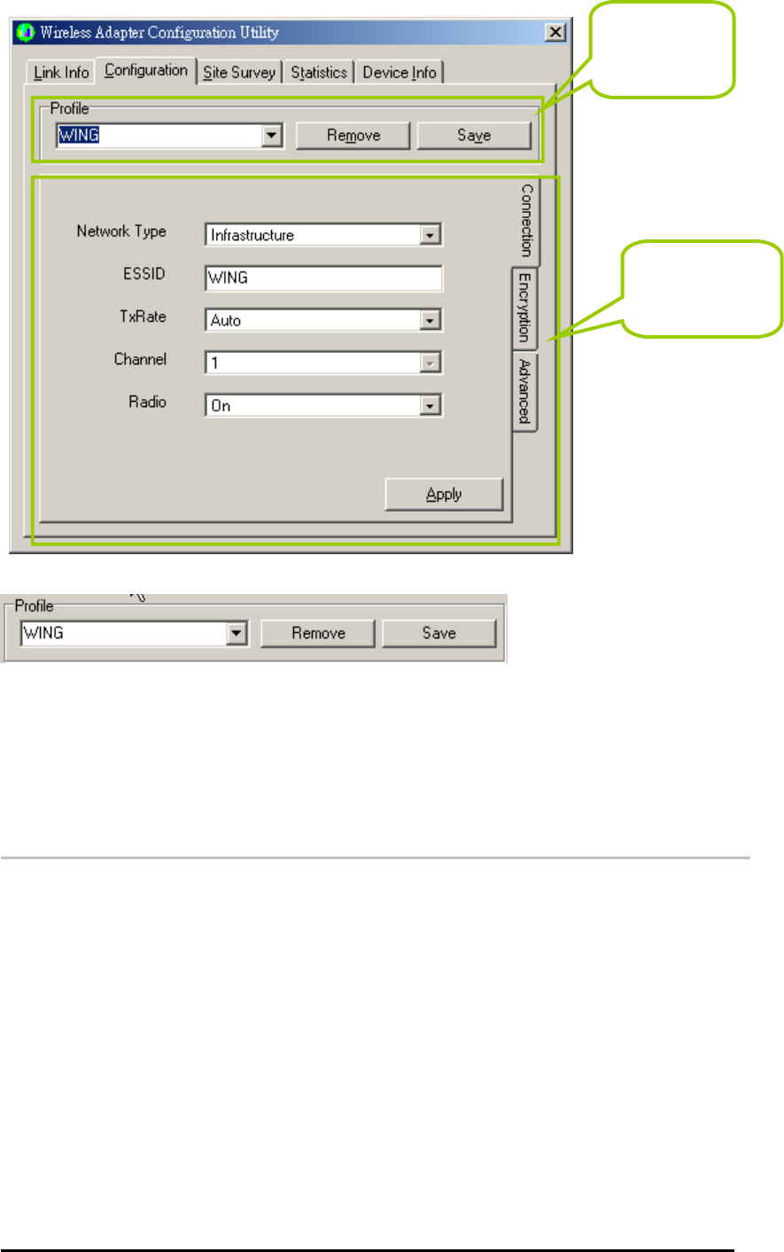
3.3 Wireless LAN Adapter Utility – Configuration
Tab
Click the Configuration Tab and the following information will be displayed. The top pane of
this page is to remove or save configuration settings. You can configure the wireless network
adapter through the bottom pane of this page. The bottom pane includes three sub-tabs
locating on the right side. Click each sub-tab, and the corresponding items will be displayed on
the bottom pane of Configuration tab. Remember to click Apply button after your configuration;
otherwise, the changes you make won’t take effect.
Wireless Mini-PCI Module
Profile: Creating a profile will save your time to re-configure network links you have
established.
Remove – Click the Remove button, and then the selected profile will be deleted.
Save – Click the Save button, and then the profile will be saved for further use.
Click the drop-down menu, select one profile you have created and click Save,
then the profile you select will be applied to the current connection.
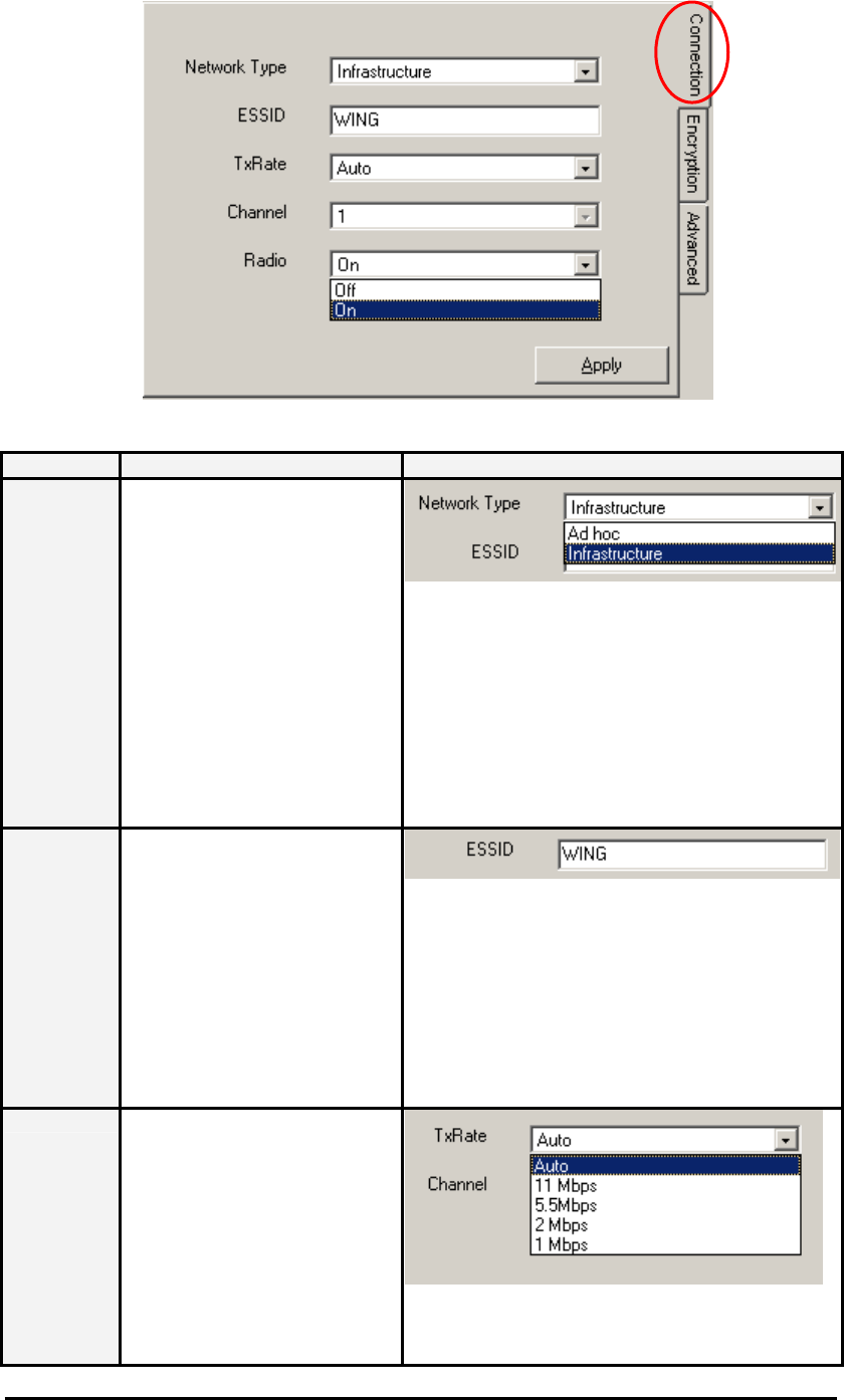
3.3.1 Configuration Tab – Connection
From the Configuration tab, click the Connection tab on the right side of the bottom pane
and the following screen will be displayed.
Create or
remove a
profile.
Configure
your adapter.
Wireless Mini-PCI Module
Connection Tab
Item Description Figure
Network
Type This wireless LAN adapter
supports two network types –
Infrastructure and Ad hoc. You
can click the down-arrow
button to select one network
type.
Infrastructure – This type of
network connection needs an
access point in range. All
communication is done
through this access point.
Ad hoc – A peer-to-peer mode
of operation. This type of link is
established from client to client
without any access point.
ESSID You can type a specific ESSID
in this field in order to establish
the link with an access point or
other computer equipped with
a wireless LAN adapter. If you
leave this field blank, and then
the wireless LAN adapter will
try to build the link with an
access point or other computer
equipped with a wireless LAN
adapter that has the better
signal and link quality.
TxRate This field provides options for
selecting data-transmitting rate
of the wireless LAN adapter.
There are five options – Auto,
1 Mbps, 2 Mbps, 5.5 Mbps and
11 Mbps. You can click the
down-arrow button to select
one option. By default, the data
rate is set to Auto allowing the
wireless LAN adapter to
ada
p
tivel
y
set the Tx rate to
Wireless Mini-PCI Module
the highest possible rate for
the WLAN condition. It’s
recommended that you select
the Auto option. If there is an
802.11g access point in the
radio range, the Tx Rate will be
changed to 54, 48, 36, 24, 18,
12, 9 and Auto.
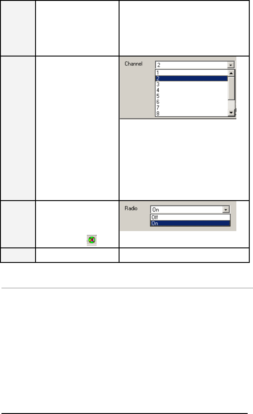
Channel This field shows the channel
number the current link uses.
In infrastructure mode, this
field shows the channel that
the connected access point
uses. So you can’t modify this
field in infrastructure mode. In
Ad hoc mode, this function is
available and you can click the
pull-down menu to select one
channel. There are 14
channels available for
communication with a Wireless
Access Point, but there may be
restrictions on which channel
can be used in some countries.
11 channels for United
States
13 channels for Europe
countries
14 channels for Japan
Radio Click the drop-down menu to
enable or disable the wireless
LAN adapter. When you select
the Off option and the utility
icon resides on the system tray
will be changed to .
Apply Click Apply button to make
your parameters take effect.
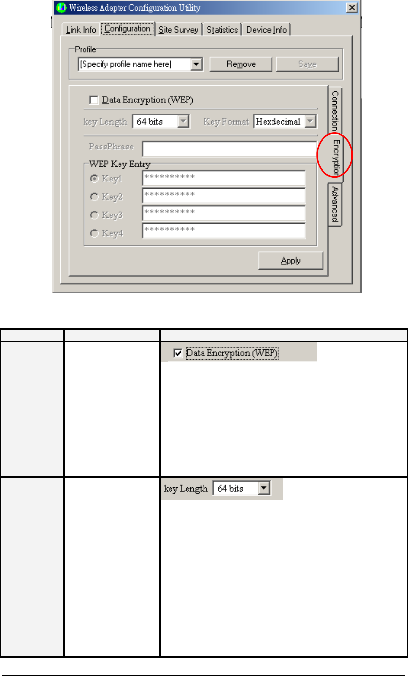
3.3.2 Configuration Tab – Encryption
From the Configuration tab, click the Encryption tab on the right side of the bottom pane
and the following screen will be displayed. The Encryption tab provides WEP (Wired
Equivalent Privacy) function to ensure a more secure networking communication and prevent
unauthorized access to your wireless network. The WEP keys configured for your wireless
device must be the same as the WEP keys configured for the access point or wireless LAN
adapter it associates.
Wireless Mini-PCI Module
Encryption tab
Item Description Figure
Data
Encryption
(WEP)
Click the box in front
of Data Encryption
(WEP) to enable the
WEP function. You
can set four different
WEP keys in WEP
Key Entry and specify
one of them to use. If
the box is not
checked, then you
can’t change WEP
related parameters.
Key Length Click the drop-down
menu to select 64
bits or 128 bits. The
128 bits gives a
higher level of
security. The
selection must be the
same between these
two connected
devices. You can see
that as the key length
option is changed,
the number of
available characters
in the WEP Key Entry
field is chan
g
ed
Wireless Mini-PCI Module
automatically.
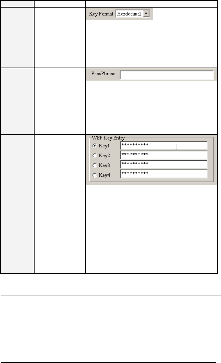
Key Format This utility supports
both Hexadecimal
and ASCII key
formats. Click the
drop-down menu to
choose one format.
Only digits 0-9 and
letters A-F are valid
entries if you select
hexadecimal format.
PassPhrase PassPhrase function
is used as a seed to
randomly generate
the WEP encryption
keys. If you use a key
generated from a
PassPhrase, you
must use the same
PassPhrase and
keys on each station.
WEP Key
Entry These four fields
allow you to set four
different 64-bit or
128-bit alphanumeric
keys for encryption.
This item is a very
convenient and
useful function when
you want to match
the WEP keys with
different vendor’s
products. After you
have set the WEP
keys for specific AP
or wireless LAN card,
instead of entering
the WEP key every
time, you just click
the radio button in
front of the WEP key
to enable the WEP
key of the associated
device.
3.3.3 Configuration Tab – Advanced
From the Configuration tab, click the Advanced tab on the right side of the bottom pane and
the following screen will be displayed. In this page, this utility gives you more flexibility to
manage the wireless LAN adapter. You can change advanced configurations, such as
fragmentation threshold, RTS/CTS threshold, Preamble type, Power Save mode and
Authentication Type.
Wireless Mini-PCI Module
Advanced tab
Item Description Figure
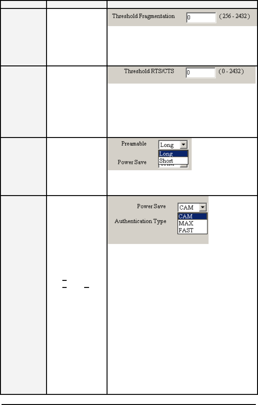
Threshold
Fragmentation This field is to define
the maximum data
frame size this
wireless LAN adapter
will transmit and to
improve the
efficiency of data
transmitting.
Threshold
RTS/CTS This field is to define
when will the wireless
LAN adapter send
out RTS/CTS frames
to reserve bandwidth
for transmission.
Type the value in this
field and the effective
range is from 0 to
3000.
Preamble There are two
options in this field.
The Short Preamble
option improves
throughput
performance. The
default setting is
Long.
Power Save This field provides
three options for the
configuration of
power management.
There are three
power saving modes.
Click the pull-down
menu to select the
mode you desire.
CAM – It
represents
Continuous
Access Mode.
Select this
option and the
wireless LAN
adapter is
always on.
MAX – It
represents the
maximum
(MAX) power
saving mode.
Select this
option to save
the maximum
power of the
wireless LAN
Wireless Mini-PCI Module
adapter.
FAST – It
represents the
fast power
saving mode.
This power
mode provides
the best
combination of
network
performance
and power
usage.
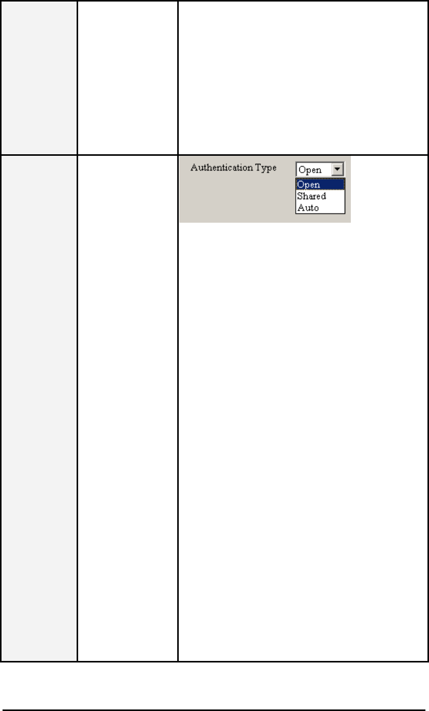
Authentication
Type Click the pull-down
menu to select Auto,
Shared or Open type.
The authentication
function is invoked
when associated to
access point. The
authentication type
you select should be
the same between
these connected
devices. If you select
A
uto mode, the driver
will auto detect the
authentication type of
the access point you
are going to
associate.
Open: With this
setting any
station in the
Wireless LAN
devices can
associate with
an Access Point
to receive and
to transmit data.
Shared: With
this setting only
stations using a
shared key
encryption
identified by the
Access Point
are allowed to
associate with
it.
Auto: With this
setting stations
can
communicate
with or without
data encryption.
Wireless Mini-PCI Module
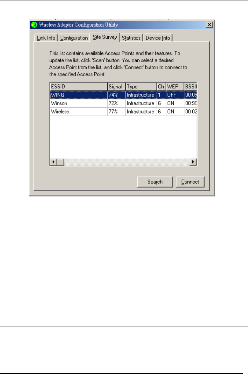
3.4 Wireless LAN Adapter Utility – Site Survey
Tab
Click the Site Survey tab and the following screen will be displayed.
From the Site Survey page, you can search all access points and wireless LAN adapters that
are within the service range of the wireless LAN adapter. The service range the wireless LAN
card supports is up to 100 meters indoor or 300 meters outdoors. Click Search button, and the
wireless LAN card will start to search access points and WLAN adapters and show the result in
the list. The list includes information about the ESSID and BSSID of the access point and
WALN adapter, the signal strength, the channel where the access point and WLAN adapter
operates, and whether or not WEP encryption is used. You can highlight the access point or
WLAN adapter you want to associate and click Connect or double click on your choice, and
the system will take you back to the Link Info tab showing you the parameters of the
connection newly established. If the wireless device you attempt to connect uses WEP
function, then the system will take you to the Configuration tab/Encryption page.
In the above figure, you can see there are three access points within the service range of the
wireless LAN card. You may click the Search button to update this list and click the scroll bar
to right to see more information the list provides.
3.5 Wireless LAN Card Utility – Statistics Tab
Click the Statistics tab and the following screen will be displayed.
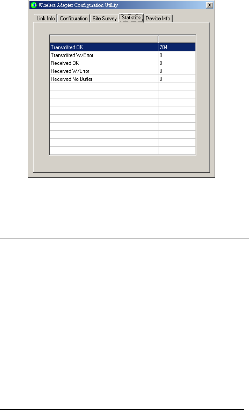
Wireless Mini-PCI Module
From the Statistics tab page, you can view the instantaneous wireless receive and transmit
data information.
3.6 Wireless LAN Adapter Utility – Device Info
Tab
Click the Device Info tab and the following screen will be displayed.
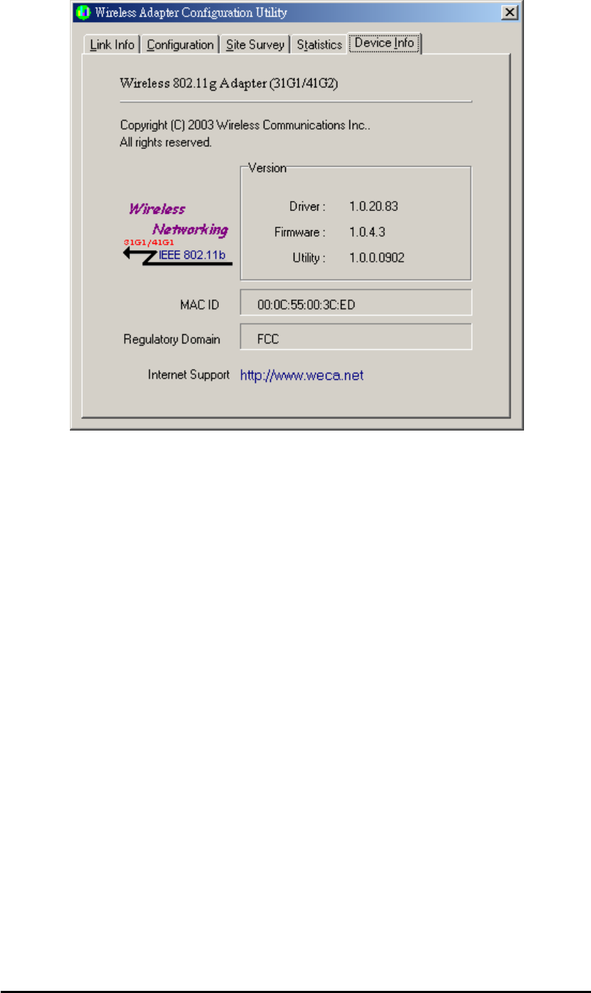
Wireless Mini-PCI Module
From the Device Info (information) page, you can view the copyright and the product version
including the diver version and utility version. The MAC address of the wireless LAN adapter
and the regulatory domain are also shown on this page.
Wireless Mini-PCI Module
Chapter4
Using WinXP Built-in
Wireless Network Configuration
Utility
There are two ways to configure the wireless LAN adapter under Windows XP operating
system. One is wireless LAN utility we provide and the other one is the Windows wireless
network configuration utility Windows XP provides. If you want to use the configuration utility
we provide, please refer to Chapter 3. The following section guides you how to use the
wireless network configuration utility Windows XP provides.
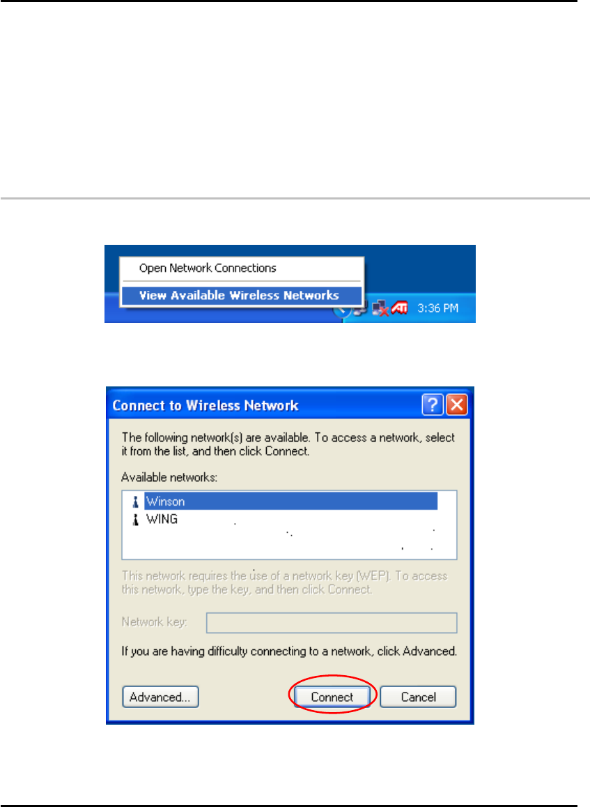
4.1 Open the Local Area connection dialog box
Right-click mouse button on the network connection icon resides on the system tray, and
click “View Available Wireless Networks”.
The following Connect to Wireless Network dialog box will be displayed. You can click
Connect to start the wireless connection or click Advanced button to do further
configuration.
Click the Advanced button and the Local Area Connection Properties dialog box will be
displayed. Click the Wireless Networks tab from the Wireless Network Connection
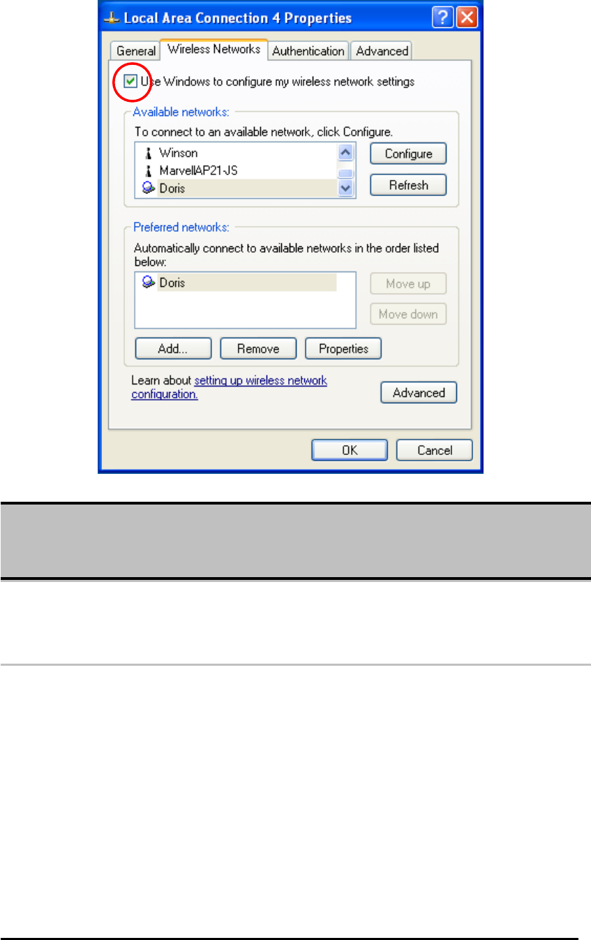
Wireless Mini-PCI Module
Properties dialog box. Select the box of “Use Windows to configure my wireless
network settings” to enable automatic wireless network configuration.
4.2 Infrastructure Mode Setup Procedure
From the Wireless Network tab, click Refresh button to update all the available network
devices in range.
Click the network name under the “Available networks” and click Configure. The
Wireless Network Properties dialog box will be displayed.
Note:
If you want to use the configuration utility we provide, you have to clear the check of “Use
Windows to configure my wireless network settings” item.
Wireless Mini-PCI Module
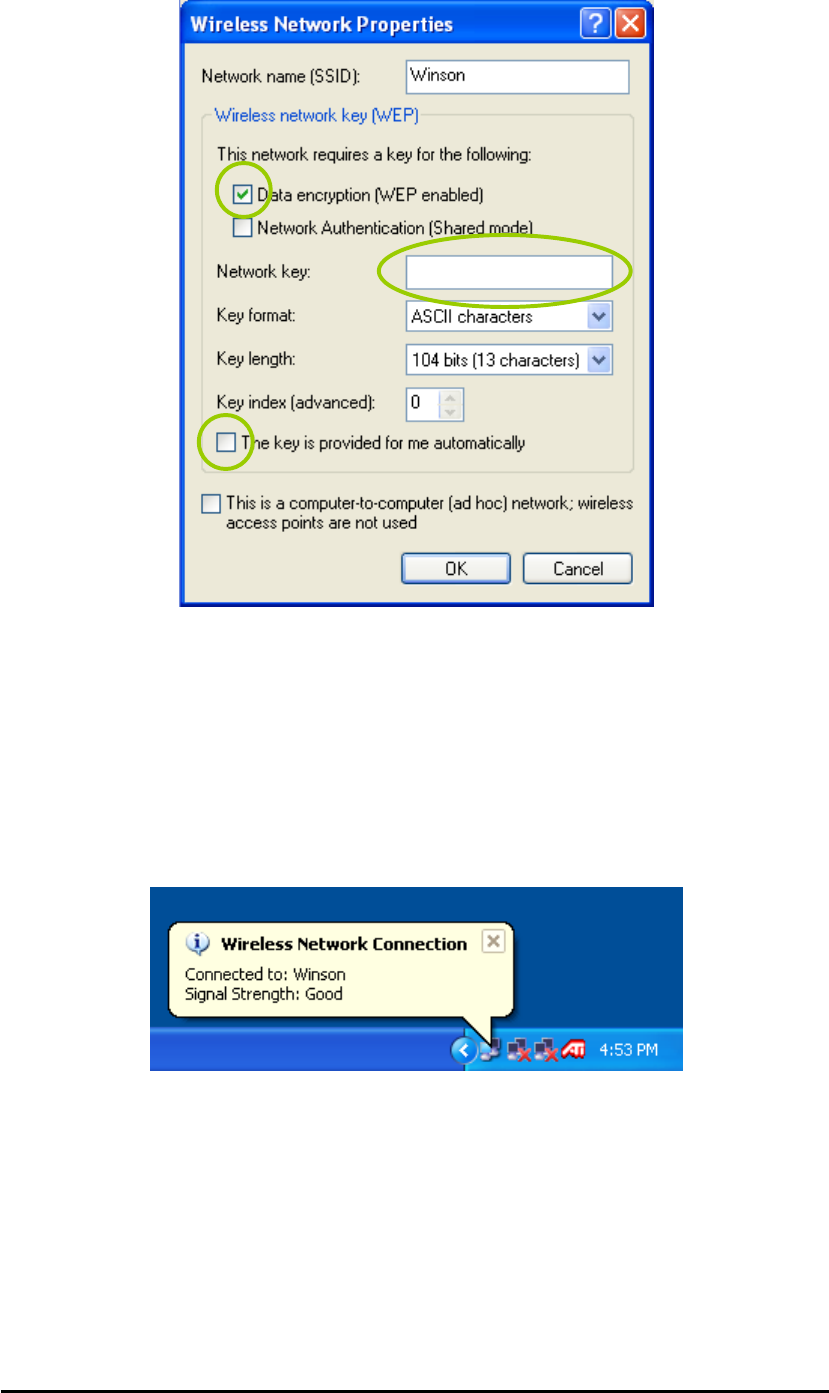
If the network you select requires WEP key, then the “Data encryption (WEP enabled)”
check box is selected by default. Select the “The key is provided for me
automatically” check box if the WEP key is automatically provided for you. The driver
will then use the Default Encryption key. If not, you have to clear the check and manually
enter the network key. In this example, you have to type the WEP keys. After you enter
the WEP keys, you can click OK to close the Wireless Network Properties dialog box and
the system will take you back to Wireless Network Connection Properties dialog box.
Click OK to save your configuration and the Wireless Network Connection Properties will
be closed.
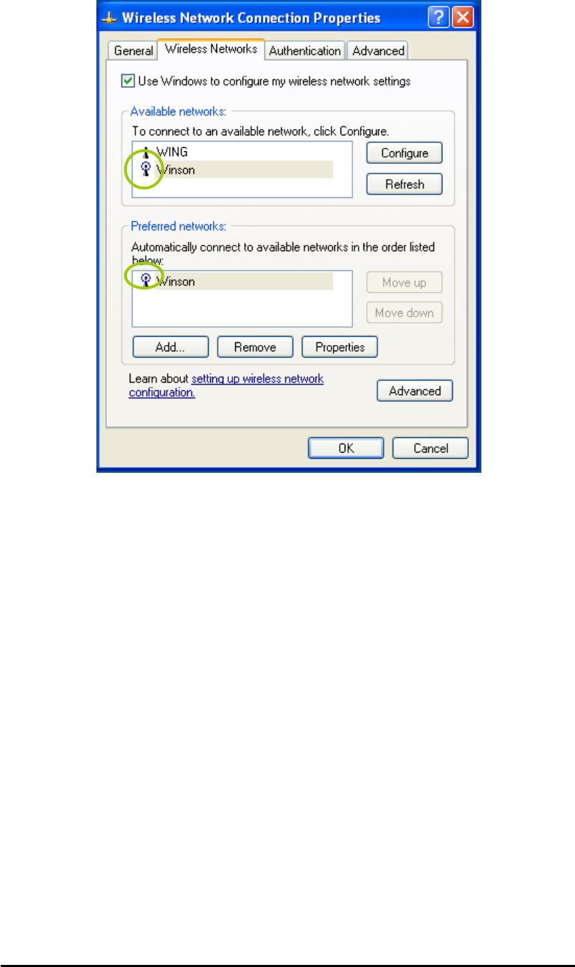
When the network connection you have configured is available, the following bubble
message will be shown on the system tray.
Right-click mouse button on the network icon and select “View Available Wireless
Network”. Click Advanced button from the Connect to Wireless Network dialog box
and you can find that there is a blue circle on the ESSID: Winson you have configured in
Wireless Network Connection Properties dialog box. It means that you have successfully
built the connection. You may refer to how to do TCP/IP setup in Windows 2000 section
to configure you wireless LAN adapter in Windows XP. After the TCP/CP configuration is
done, you can access the Internet through the wireless connection you have built.
Wireless Mini-PCI Module
Furthermore, you can highlight a network connection and click Move up or Move down
to change the order of the wireless networks in the Preferred networks. For Windows
XP, it will always choose the first one in the Preferred networks to connect. To remove a
wireless network from the list of preferred networks, select the wireless network that you
want to remove, and then click Remove.
Wireless Mini-PCI Module
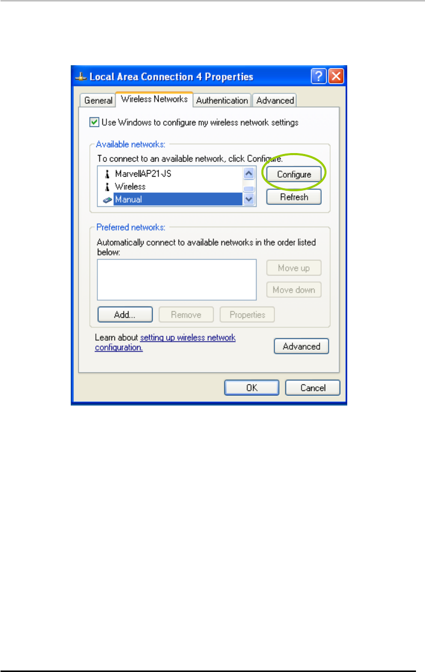
4.3 Ad-hoc Mode Setup Procedure
Click Refresh button to update all available devices in range from Wireless Network
Connection.
Select the ad hoc network name under “Available networks” in the Wireless Networks
tab, and click Configure.
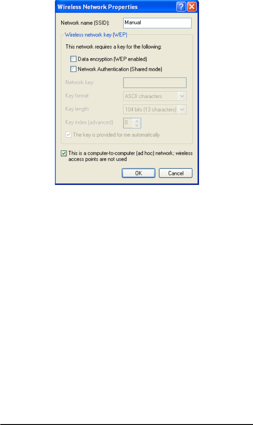
In the Wireless Network Properties dialog box, the “This is a computer-to-computer (ad
hoc) network; wireless access points are not used” check box is selected by default.
If the network adapter you want to connect has enabled the WEP function and then the
“Data encryption (WEP enabled)” check box is checked. You can select the “The key is
provided for me automatically” check box if the WEP key is automatically provided for
you. The driver will then use the Default Encryption key. If not, you have to clear the
check and manually enter the network key. After you enter the WEP keys, you can click
OK to close the Wireless Network Properties dialog box and will go back to Wireless
Network Connection Properties dialog box.
Wireless Mini-PCI Module
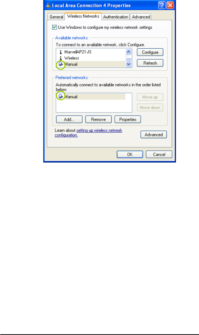
Click OK to save your configuration and close the Local Area Connection Properties
dialog box. Right-click mouse button on the network icon on the system tray and open the
Connect to Wireless Network dialog box again. Click Advanced button, and you can see
that there is a blue circle on the wireless network adapter icon.
Wireless Mini-PCI Module
You may refer to how to do TCP/IP setup in Windows 2000 section to configure you
wireless LAN adapter in Windows XP. After the TCP/CP configuration is done, you can
share data between these wireless devices.
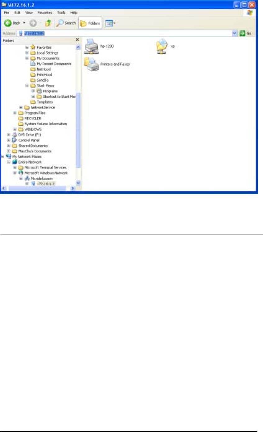
Open Windows Explorer and type the connected wireless network adapter IP address in
the Address field. The folder that remote WLAN adapter share will be displayed. Now ,
you can share data between these two desktop or laptop equipped with a wireless
network adapter.
Wireless Mini-PCI Module
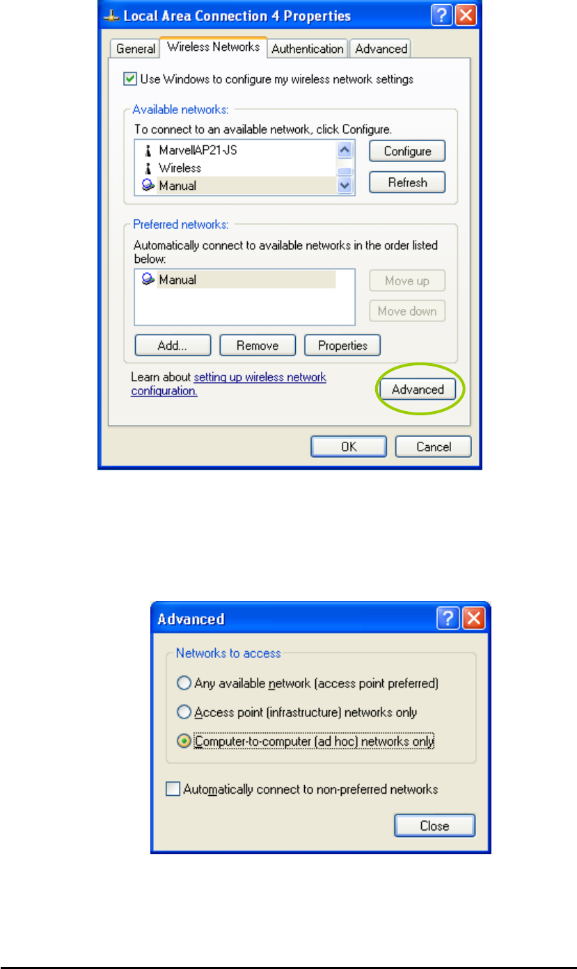
4.4 Network Operating Mode Selection
Click “Advanced” button from the Local Area Connection dialog box, and you can select
network operating mode you want to use.
Wireless Mini-PCI Module
If you want to connect to an ad hoc network only, you can click the radio button of
“Computer-to-computer (ad hoc) networks only”. Click the radio button of “Access point
(infrastructure) networks only”, and only the available access points in range will be
displayed in the available networks box. You can click the radio button of “Any available
network (access point preferred)”, and then both access points and wireless network
adapters will be displayed in the available networks box.