Cheng Uei Precision Industry 20200000 802.11b/g Router User Manual ManualNew
Cheng Uei Precision Industry Co., Ltd. 802.11b/g Router ManualNew
UserManual.wiki
>
Cheng Uei Precision Industry
>
20200000 User Manual
>
User Manual Part 2
Contents
1.
User Manual Part 1
2.
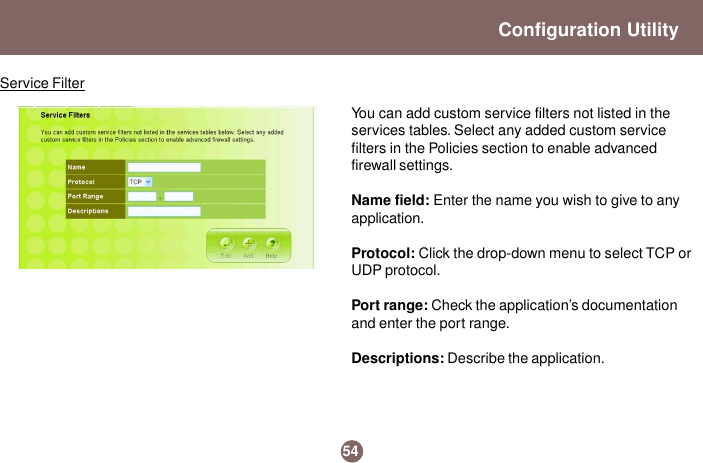
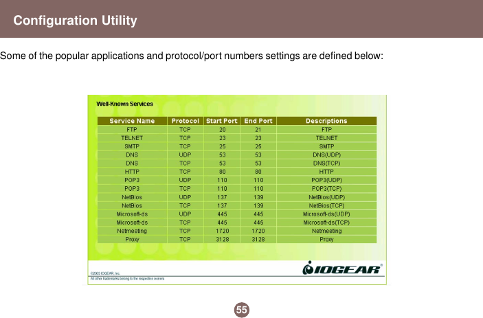
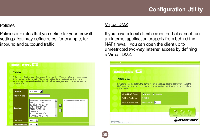
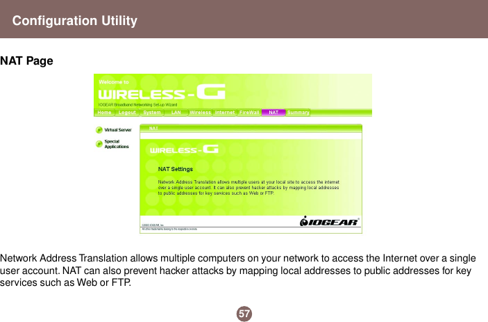
User Manual Part 2
User Manual Part 2
Navigation menu
Upload a User Manual
Namespaces
Wiki Guide
HTML
PDF
Info
Views
User Manual
Discussion / Help
Navigation