Chengdu Ebyte Electronic Technology E32-TTL-100 Wireless transceiver module User Manual E32 TTL 100 Datasheet V1 0
Chengdu Ebyte Electronic Technology Co., Ltd. Wireless transceiver module E32 TTL 100 Datasheet V1 0
User manual
E32-TTL-100 Datasheet V1.0 Chengdu Ebyte Electronic Technology Co., Ltd.
Purchase the sample:http://www.aliexpress.com/store/2077046 Website: www.cdebyte.com
Professional R&D RF Module 2.4G、915M、868M、780M、490M、434M、315M、230M、170M Wireless Module
Page 1 of 14 The copyright and the product has the Chengdu Ebyte Electronic Technology Co., Ltd. All
E32-TTL-100 Datasheet V1.0
.1.Introduction E32-TTL-100
1.1 Feature E32-TTL-100
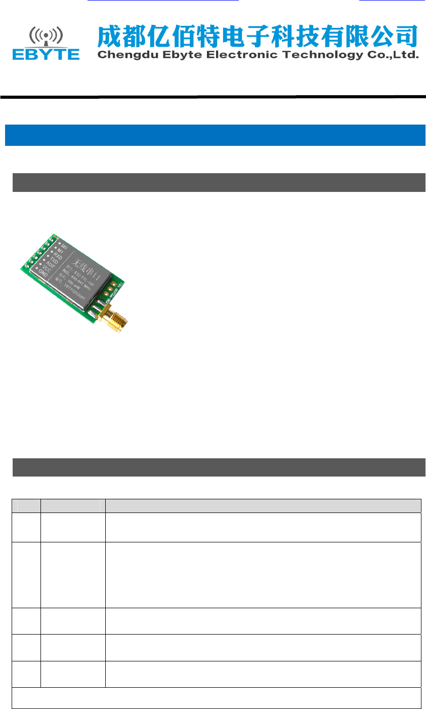
E32-TTL-100 is a wireless transceiver module with LoRa spread-spectrum
technology, operates at 434MHz, based on original imported RFIC SX1278
from SEMTECH, transparent transmission is available, TTL level. The module
adopts LoRa spread-spectrum technology, which means the transmitting
distance is much longer than before. The advantages of this module is more
concentrated power density and better anti-interference performance.
The module features FEC (Forward Error Correction) algorithm, which
ensure its high coding efficiency & good correction performance. In the case
of sudden interference, it can correct the interfered data packets automatically,
so that the reliability & transmission range are improved correspondingly. But without FEC, those date packets can
only be dropped.
The module has the function of data encryption & compression. The data of the module transmit in the air
features randomness. And with the rigorous encryption & decryption, data interception becomes pointless. The
function of data compression can decrease the transmission time & probability of being interference, while
improving the reliability & transmission efficiency.
1.2 Basic usage E32-TTL-100
No. Usage Description
1 Transparent
transmission
Default
Module A transmits 01 02 03 to module B, then module B receives 01 02 03.
2 Fixed
transmission
Module can communicate with other modules in different channels, easy for
networking and repeater.
Module A transmits AA BB CC to module B (address: 0x00 01, channel: 0x80), HEX
format is 00 01 80 AA BB CC (00 01 refers to the address of module B, 80 refers to the
channel of module B), then module B receives AA BB CC (only module B).
3 Broadcast
transmission
Set the module address as 0xFFFF, then the module can communicate with other
modules in same channel.
4 Power-saving In power-saving mode, the module’s maximum receiving response time is 2000ms,
which the average current is below 50uA.
5 Sleep When the module works in sleep mode, transmitting & receiving is not available,
while the configuration is available. The typical current is 2.0uA in this mode.
See more details in related manual about fixed transmission and broadcast transmission.

E32-TTL-100 Datasheet V1.0 Chengdu Ebyte Electronic Technology Co., Ltd.
Purchase the sample:http://www.aliexpress.com/store/2077046 Website: www.cdebyte.com
Professional R&D RF Module 2.4G、915M、868M、780M、490M、434M、315M、230M、170M Wireless Module
Page 2 of 14 The copyright and the product has the Chengdu Ebyte Electronic Technology Co., Ltd. All
1.3 Electrical parameter E32-TTL-100
No. Parameter item Parameter details & Description
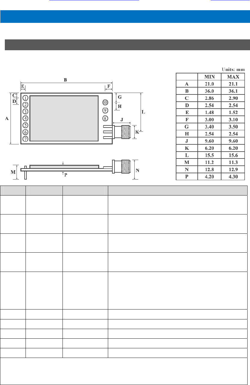
1 Size 21 * 36mm,
Without antenna and SMA
2 Frequency Band 434MHz
3 Connector 1*7*2.54mm
Plug-in
4 Supply voltage 2.3 - 5.5V DC
Note: the voltage higher than 5.5V is forbidden
5 Communication level UART, USART
6 Operation Range
About 3000m
Test condition:clear and open area& maximum power, height:> 2m,air
date rate: 2.4kbps
7 Transmitting power
Four optional level(0-3),step by 3dB
8 Air data rate Default 2.4kbps
Can be configured to 0.3、1.2、2.4、4.8、9.6、19.2kbps
9 Standby current 2.0uA
M1=1,M0=1 ( Mode 3 )
10 Transmitting current 110mA
11 Receiving current 14.5mA(Mode 0 or Mode 1)
Minimum 30uA(Mode 2 + 2s wake-up time)
12 Communication
interface
UART, 8N1、8E1、8O1,
Eight kinds of UART baud Rate, from 1200 to 115200 bps
13 Driving mode UART can be configured to push-pull/high pull, open-drain
14 Transmitting length 512 bytes buffer,58 bytes per package
15 Receiving length 512 bytes buffer,58 bytes per package
16 Address 65536 configurable addresses
Easy for network, broadcast and fixed transmission
17 RSSI support Built-in intelligent processing
18 Sensitivity -130dbm@0.3kbps
Sensitivity has nothing to do with serial baud rate and timing
19 Antenna type SMA-K
External thread hole, 50 ohm impedance
20 Operating
temperature -40 ~ +85℃
21 Operating
temperature 10% ~ 90%
22 Storage temperature -40 ~ +125℃
E32-TTL-100 Datasheet V1.0 Chengdu Ebyte Electronic Technology Co., Ltd.
Purchase the sample:http://www.aliexpress.com/store/2077046 Website: www.cdebyte.com
Professional R&D RF Module 2.4G、915M、868M、780M、490M、434M、315M、230M、170M Wireless Module
Page 3 of 14 The copyright and the product has the Chengdu Ebyte Electronic Technology Co., Ltd. All
.2.Functional description E32-TTL-100
2.1 Pin definition E32-TTL-100
Pin No. Pin item Pin direction Pin application
1 M0 Input
(weak pull-up)
Work with M1 & decide the four operating modes.
Floating is not allowed, can be ground.
2 M1 Input
(weak pull-up)
Work with M0 & decide the four operating modes.
Floating is not allowed, can be ground.
3 RXD Input TTL UART inputs, connects to external (MCU, PC) TXD output
pin. Can be configured as open-drain or pull-up input.
4 TXD Output TTL UART outputs, connects to external RXD (MCU, PC) input
pin. Can be configured as open-drain or push-pull output
5 AUX Output
To indicate module’s working status & wakes up the external
MCU. During the procedure of self-check initialization, the pin
outputs low level. Can be configured as open-drain output or
push-pull output (floating is allowed).
6 VCC Power supply 2.3V-5.5V DC
7 GND Ground
8 Fixing hole Fixing hole
9 Fixing hole Fixing hole
10 Fixing hole Fixing hole
★★★ E32-TTL-100 can be compatible with other E32 series. ★★★
E32-TTL-100 Datasheet V1.0 Chengdu Ebyte Electronic Technology Co., Ltd.
Purchase the sample:http://www.aliexpress.com/store/2077046 Website: www.cdebyte.com
Professional R&D RF Module 2.4G、915M、868M、780M、490M、434M、315M、230M、170M Wireless Module
Page 4 of 14 The copyright and the product has the Chengdu Ebyte Electronic Technology Co., Ltd. All
2.2 Connect to MCU E32-TTL-100
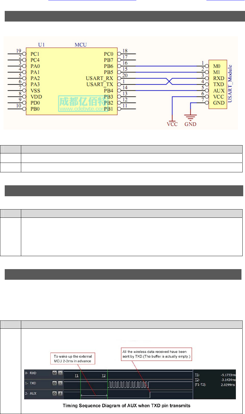
No. Description(STM8L MCU)
1 The UART module is TTL level.
2 For some MCU works at 5VDC, it may need to add 4-10K pull-up resistor for the TXD & AUX pin.
2.3 Reset E32-TTL-100
No. Description
1
When the module is powered, AUX outputs low level immediately, conducts hardware self-check and
set the operating mode on the basis of the user parameters. During the process, the AUX keeps low
level. After the process completes, the AUX outputs high level and starts to work as per the operating
mode combined by M1 and A0. Therefore, the user needs to wait the AUX rising edge as the starting
point of module’s normal work.
2.4 AUX description E32-TTL-100
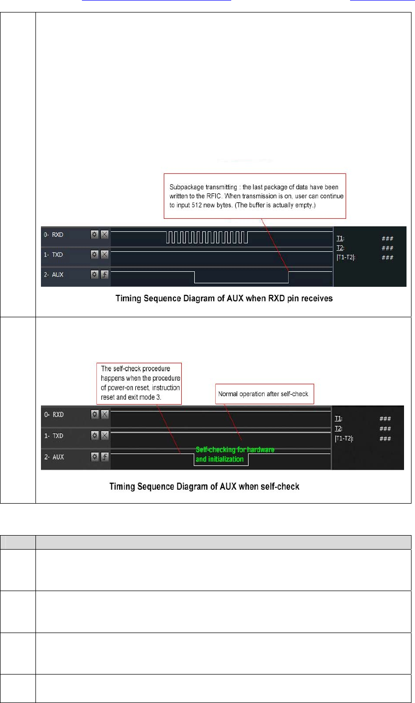
AUX Pin can be used as indication for wireless send & receive buffer and self-check. It can indicate whether
there are data that are yet to send through wireless, or whether all wireless data has sent through UART, or
whether the module is still in the process of self-check initialization.
No. Description
1
【Indication of UART output】can be used to wake up external MCU.
E32-TTL-100 Datasheet V1.0 Chengdu Ebyte Electronic Technology Co., Ltd.
Purchase the sample:http://www.aliexpress.com/store/2077046 Website: www.cdebyte.com
Professional R&D RF Module 2.4G、915M、868M、780M、490M、434M、315M、230M、170M Wireless Module
Page 5 of 14 The copyright and the product has the Chengdu Ebyte Electronic Technology Co., Ltd. All
2
【Indication of wireless transmitting】
Buffer (empty): the internal 512 bytes data in the buffer are written to the RFIC (Auto
subpackage). When AUX=1, the user can input data less than 512 bytes continuously without
overflow.
Buffer (not empty): when AUX=0, the internal 512 bytes data in the buffer have not written to
the RFIC completely. If the user starts to transmit data at this circumstance, it may cause
overtime when the module is waiting for the user date, or transmitting wireless subpackage.
Notes: When AUX = 1, it does not mean that all the UART data of the module have been
transmitted already, perhaps the last packet of data is still in transmission.
3
【Configuration procedure of module】
Only happened in the process of power-on and exit sleep mode.
No. Notes for AUX
1
For function 1 & function 2 mentioned above, the priority should be given to the one with low
level output, which means if it meets each of any low level output condition, AUX outputs low
level, if none of the low level condition is meet, AUX outputs high level.
2
When AUX outputs low level, it means the module is busy & cannot conduct operating mode
checking.
After AUX outputs high level 1ms later, it will complete the mode-switch task.
3
After switching to new operating mode, it won’t be work in the new mode immediately until
AUX rising edge 2ms later.
If AUX is on the high level, the operating mode switch can be effect immediately.
4 When the user switches to other operating modes from mode 3 (sleep mode) or it’s still in reset
process, the module will reset user parameters, during which AUX outputs low level.

E32-TTL-100 Datasheet V1.0 Chengdu Ebyte Electronic Technology Co., Ltd.
Purchase the sample:http://www.aliexpress.com/store/2077046 Website: www.cdebyte.com
Professional R&D RF Module 2.4G、915M、868M、780M、490M、434M、315M、230M、170M Wireless Module
Page 6 of 14 The copyright and the product has the Chengdu Ebyte Electronic Technology Co., Ltd. All
.3.Operating mode E32-TTL-100
Contents in below table are the introduction of input status of M1 & M0 and their corresponding mode:
Mode(0-3) M1 M0 Mode introduction Remark
Mode 0
Normal 0 0 UART and wireless channel is opened,
transparent transmission is on.
The receiver must works
in mode 0 or mode 1
Mode 1
Wake-up 0 1
UART and wireless channel is opened. The
difference between normal mode and wake-up
mode is it will add preamble code automatically
before data packet transmission so that it can
awaken the receiver works in mode 2.
The receiver can works
in mode 0, mode 1 or
mode 2.
Mode 2
Power-savin
g
1 0
UART is disabled. Wireless module works at
WOR mode (wake on radio). It will open the
UART and transmit data after receive the
wireless data.
1,the transmitter must
works in mode 1
2,transmitting is not
allowed in this mode
Mode 3
Sleep 1 1 Parameter setting.
3.1 Mode switch E32-TTL-100
No. Remarks
1
The user can decide the operating mode by the combination of M1 and M0. The two GPIO of MCU can
be used to control the mode-switch. After modifying M1 or M0, it will start to work in new mode 1 ms
later if the module is free. If there are any serial data that is yet to finish wireless transmitting, it will
start to work in new mode after the UART transmitting finishing. After the module receives the wireless
data & transmits the data through serial port, it will start to work in new mode after the transmitting
finishing. Therefore, the mode-switch is only workable when AUX outputs 1, otherwise it will delay.
2
For example, in mode 0 or mode 1, if the user inputs massive data consecutively and switches
operating mode at the same time, the mode-switch operation is invalid. New mode checking can only
be started after all the user’s data process completing. It is recommended that after check AUX
pinout status and wait 2ms after AUX outputs high level, then switch the mode.
3
If the module switches from other modes to stand-by mode, it will be work in stand-by mode only
after all the remained data process completing. The feature can be used to save power consumption.
For example, the transmitter works in mode 0, after the external MCU transmits data “12345”. It can switch to
sleep mode immediately but not wait the rising edge of the AUX pin, also the user’s main MCU will go
dormancy immediately. Then the module will transmit all the data through wireless transmission & go
dormancy 1ms later automatically. Which reduce MCU working time & save power.
4
Likewise, this feature can be used in any mode-switch. The module will start to work in new mode
within 1ms after completing present mode task, which enable the user to omit the procedure of AUX
inquiry and switch mode swiftly. For example, when switch from transmitting mode to receiving mode,
the user MCU can go dormancy in advance of mode-switch, using external interrupt function to get
AUX change so that the mode-switch can be done.
5
This operation is very flexible and efficient. It is totally designed on the basis of the user MCU’s
convenience, at the same time reduce the whole system work load as much as possible, increase the
efficiency of system work and reduce power consumption.

E32-TTL-100 Datasheet V1.0 Chengdu Ebyte Electronic Technology Co., Ltd.
Purchase the sample:http://www.aliexpress.com/store/2077046 Website: www.cdebyte.com
Professional R&D RF Module 2.4G、915M、868M、780M、490M、434M、315M、230M、170M Wireless Module
Page 7 of 14 The copyright and the product has the Chengdu Ebyte Electronic Technology Co., Ltd. All
3.2 Normal mode(Mode 0) E32-TTL-100
When M1 = 0 & M0 = 0, module works in mode 0
Transmitting
The module can receive the user data from serial port, and transmit wireless data
package which length is 58 bytes. When the data inputted by user is up to 58 byte, the
module will start wireless transmission. During which the user can input data
continuously for transmission.
When the required transmission bytes is less than 58 byte, the module will wait 3-byte
time and treat it as data termination unless continuous data inputted by user. Then the
module will transmit all the data through wireless channel.
When the module receives the first data packet from user, the AUX outputs low level.
After the module transmit all the data into RF chip & start transmission, AUX outputs
high level.
At this time, it means that the last wireless data package transmission has started, which
enable the user to input another 512 bytes continuously. The data package transmitted
from the module works in mode 0 can only be received by the module works in mode 0
or 1.
Receiving
The module keeps the wireless receive function on, it can receive the data packet
transmitted from the module works in mode 0 & mode 1. After receiving the data
packet, the AUX outputs low level, 5ms later the module starts to transmit wireless data
through serial port TXD pin. After all the wireless data have been transmitted via serial
port, the module AUX outputs high level.
3.3 Wake-up mode(Mode 1) E32-TTL-100
When M1 = 0 & M0 = 1, module works in mode 1.
Transmitting
The condition of data packet transmission & AUX function is the same as mode 0. The
only difference is that the module will add preamble code before each data packet
automatically. The preamble code length depends on the wake-up time set in the user
parameters. The purpose of the preamble code is waking up the receiving module works
in mode 2. Therefore, the data package transmitted from mode 1 can be received by
mode 0, mode1 and mode 2.
Receiving The same as that in mode 0.
3.4 Power-saving mode(Mode 2) E32-TTL-100
When M1 = 1 & M0 = 0, module works in mode 2.
Transmitting UART is closed, the module cannot receive any serial port data from outside MCU. Hence
the module works in this mode does not have the function of wireless transmission.
Receiving
In mode 2, it is required the date transmitter works in mode 1.
The wireless module monitors the preamble code at regular time. Once it gets the
preamble code, it will remain as receive status and wait for the completion of the entire
valid date package receives. Then the module lets the AUX outputs low level, 5ms later
opens the serial port to transmit received wireless data through TXD. Finally AUX outputs
high level after process completing.
E32-TTL-100 Datasheet V1.0 Chengdu Ebyte Electronic Technology Co., Ltd.
Purchase the sample:http://www.aliexpress.com/store/2077046 Website: www.cdebyte.com
Professional R&D RF Module 2.4G、915M、868M、780M、490M、434M、315M、230M、170M Wireless Module
Page 8 of 14 The copyright and the product has the Chengdu Ebyte Electronic Technology Co., Ltd. All
The wireless module stays in “power-saving – monitoring” working status (polling). By
setting different wake-up time, the module can have different receive response delay (2s
maximum) and average power consumption (30uA minimum). The user needs to achieve
a balance between communication delay time & average power consumption.
3.5 Sleep mode (Mode 3) E32-TTL-100
When M1=1,M0=1,module works in mode 3
Transmitting N/A
Receiving N/A
Parameter
setting
This mode can be used for parameter setting. It uses serial port 9600 & 8N1 to set
module working parameters through specific instruction format. (pls refer to parameters
setting for details)
Notes
When the mode changes from stand-by mode to others, the module will reset its
parameters, during which the AUX keeps low level and then outputs high level after reset
completing. It is recommended to check the AUX rising edge for user.
3.6 Quick communication test E32-TTL-100
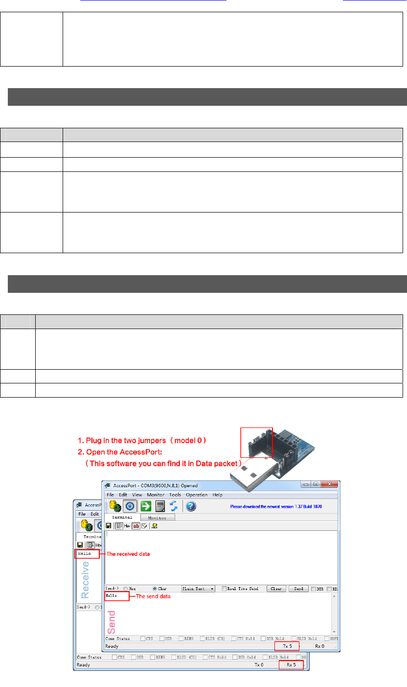
Steps Operation
1
Plug the USB test board (E15-USB-T2) into computer, make sure the driver is installed correctly.
Plug mode-select jumper in the USB test board (M1 = 0,M0 = 0), make the module work in
mode 0.
2 Optional power supply, 3.3V or 5V.
3 Operate AccessPort software and select the correct serial port code. See figure 7.
E32-TTL-100 Datasheet V1.0 Chengdu Ebyte Electronic Technology Co., Ltd.
Purchase the sample:http://www.aliexpress.com/store/2077046 Website: www.cdebyte.com
Professional R&D RF Module 2.4G、915M、868M、780M、490M、434M、315M、230M、170M Wireless Module
Page 9 of 14 The copyright and the product has the Chengdu Ebyte Electronic Technology Co., Ltd. All
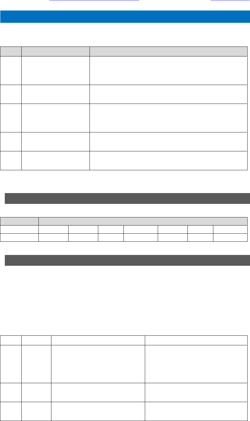
.4.Instruction format E32-TTL-100
In sleep mode(mode 3:M1=1, M0=1), it supports below instructions on list.
(Only support 9600 and 8N1 format when setting)
No. Instruction format Illustration
1 C0 + working parameters
C0 + 5 bytes working parameters are sent in hexadecimal format.
6 bytes in total and must send in succession. ( Save the parameters
when power-down )
2 C1 C1 C1 Three C1 are sent in hexadecimal format. The module returns the
saved parameters and must send in succession.
3 C2 + working parameters
C2 + 5 bytes working parameters are sent in hexadecimal format.
6 bytes in total and must send in succession. ( Not save the
parameters when power-down )
4 C3 C3 C3 Three C3 are sent in hexadecimal format. The module returns the
version information and must send in succession.
5 C4 C4 C4 Three C4 are sent in hexadecimal format. The module will reset
one time and must send in succession.
4.1 Default parameter E32-TTL-100
Default parameter values:C0 00 00 1A 17 44
Model Frequency Address Channel Air data rate Baud rate Parity
E32-TTL-100 434MHz 0x0000 0x17 2.4kbps 9600 8N1
4.2 Parameter setting instruction E32-TTL-100
The difference between C0 command and C2 command is that C0 command will write parameters into the
internal flash memory and can be saved when power down, while C2 command cannot be saved when power
down, because C2 command is temporarily mend instruction.
C2 is recommended for the occasion that need to change the operating parameters frequently,
Like C2 00 00 1A 17 44.
No. Item Description Remark
0 HEAD Fix 0xC0 or 0xC2, it means this frame
data is control command
Must be 0xC0 or 0xC2
C0: Save the parameters when power-down
C2: Not save the parameters when
power-down
1 ADDH High address byte of module
(the default 00H)
00H-FFH
2 ADDL Low address byte of module
(the default 00H)
00H-FFH

E32-TTL-100 Datasheet V1.0 Chengdu Ebyte Electronic Technology Co., Ltd.
Purchase the sample:http://www.aliexpress.com/store/2077046 Website: www.cdebyte.com
Professional R&D RF Module 2.4G、915M、868M、780M、490M、434M、315M、230M、170M Wireless Module
Page 10 of 14 The copyright and the product has the Chengdu Ebyte Electronic Technology Co., Ltd. All
3 SPED Rate parameter,including UART baud
rate and air date rate
7,6 UART parity bit
00:8N1(default)
01:8O1
10:8E1
11:8N1(equal to 00)
------------------------------------------
5,4,3 TTL UART baud rate(bps)
000:1200bps
001:2400bps
010:4800bps
011:9600bps(default)
100:19200bps
101:38400bps
110:57600bps
111:115200bps
------------------------------------------
2,1,0 Air date rate(bps)
000:0.3Kbps
001:1.2Kbps
010:2.4Kbps(default)
011:4.8Kbps
100:9.6Kbps
101:19.2Kbps
110:19.2Kbps
111:19.2Kbps
UART mode can be different between
communication parties
-----------------------------------------------
UART baud rate can be different
between communication parties
The UART baud rate has nothing to do
with wireless transmission parameters
& won’t affect the wireless transmit /
receive features.
----------------------------------------------
The lower the air date rate, the longer
the transmitting distance, better
anti-interference performance and
longer transmitting time
The air date rate must keep the same
for both communication parties.
4 CHAN 7,6,5: N/A
------------------------------------------
4-0:Communication channel, default
17H(434MHz)
0(recommended)
-------------------------------------------------
00H-1FH
5 OPTION 7, Fixed transmission(similar to
MODBUS)
0: Transparent transmission
mode(default)
1: Fixed transmission mode
------------------------------------------
6 IO drive mode(the default 1)
1:TXD and AUX push-pull
outputs,
RXD pull-up inputs
0:TXD、AUX open-collector
In fixed transmission mode, the first
three bytes of each user's data frame
can be used as high/low address and
channel. The module changes its
address and channel when transmit.
And it will revert to original setting
after complete the process.
-----------------------------------------------
This bit is used to the module internal
pull-up resistor. It also increases the
level’s adaptability in case of open
drain. But in some cases, it may need
external pull-up resistor.

E32-TTL-100 Datasheet V1.0 Chengdu Ebyte Electronic Technology Co., Ltd.
Purchase the sample:http://www.aliexpress.com/store/2077046 Website: www.cdebyte.com
Professional R&D RF Module 2.4G、915M、868M、780M、490M、434M、315M、230M、170M Wireless Module
Page 11 of 14 The copyright and the product has the Chengdu Ebyte Electronic Technology Co., Ltd. All
outputs,
RXD open-collector inputs
----------------------------------------
5,4,3 wireless wake-up time(for the
receiver, it means the monitor interval
time ,while for the transmitter it means
continuously sending preamble code
time.)
000:250ms(default)
001:500ms
010:750ms
011:1000ms
100:1250ms
101:1500ms
110:1750ms
111:2000ms
-----------------------------------------
2, FEC switch
0:Turn off FEC
1:Turn on FEC(Default)
-----------------------------------------
1, 0 transmission power
(approximation)
-----------------------------------------------
The transmit & receive module work in
mode 0, whose delay time is invalid &
can be arbitrary value.
The transmitter works in mode 1 can
transmit the preamble code of the
corresponding time continuously.
When the receiver works in mode 2,
the time means the monitor interval
time (wireless wake-up). Only the data
from transmitter that works in mode 1
can be received.
The wake-up time set by transmitter
cannot be less than the monitor
interval time of receiver; otherwise, it
may lead to data loss. In case of
two-way communication, both parties
should keep the wake-up time the
same.
The longer the wake-up time, the
lower the average receive current
consumption.
------------------------------------------------
After turn off FEC, the actual data
transmission rate increases while
anti-interference ability decreases.
Also the transmission distance is
relatively short.
Both communication parties must
keep on the same pages about
turn-on or turn-off FEC.
-----------------------------------------------
The external power must make sure
the ability of current output more than
200mA and ensure the power supply
ripple within 100mV.
Low power transmission is not
recommended due to its low power
supply efficiency.
E32-TTL-100 Datasheet V1.0 Chengdu Ebyte Electronic Technology Co., Ltd.
Purchase the sample:http://www.aliexpress.com/store/2077046 Website: www.cdebyte.com
Professional R&D RF Module 2.4G、915M、868M、780M、490M、434M、315M、230M、170M Wireless Module
Page 12 of 14 The copyright and the product has the Chengdu Ebyte Electronic Technology Co., Ltd. All
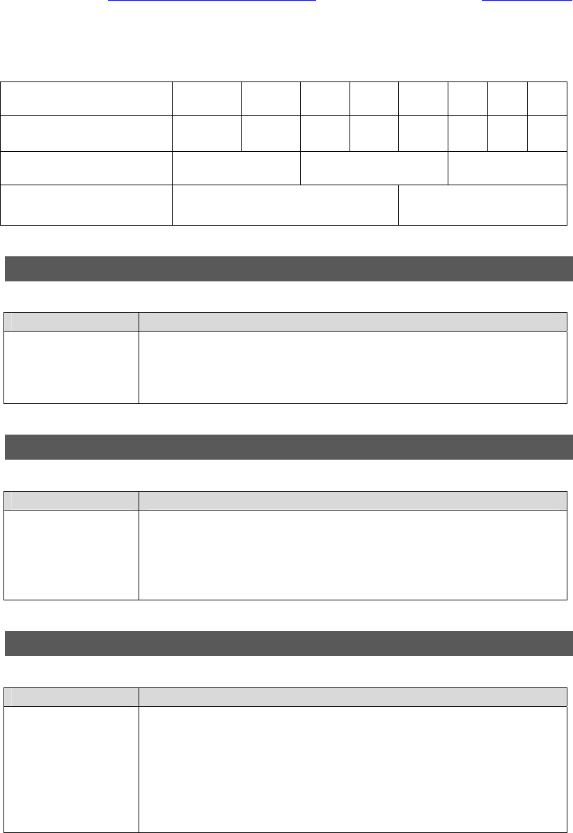
For example: The meaning of No.3 "SPED" byte:
The binary bit of the byte 7 6 5 4 3 2 1 0
The specific value
(user configures) 0 0 0 1 1 0 1 0
Meaning UART parity bit 8N1 UART baud rate is 9600 Air date rate is 2.4k
Corresponding hexadecimal 1 A
4.3 Reading operating parameters E32-TTL-100
Instruction format Description
C1+C1+C1
In sleep mode(M0=1,M1=1),
User gives the module instruction (HEX format): C1 C1 C1,
Module returns the present configuration parameters.
For example, C2 00 00 1A 17 44.
4.4 Reading version number E32-TTL-100
Instruction format Description
C3+C3+C3
In sleep mode(M0=1,M1=1),
User gives the module instruction (HEX format): C3 C3 C3,
Module returns its present version number, for example C3 32 xx yy.
32 here means the module model (E32 series); xx is the version number and yy
refers to the other module features.
4.5 Reset instruction E32-TTL-100
Instruction format Description
C4+C4+C4
In sleep mode(M0=1,M1=1),
User gives the module instruction (HEX format): C4 C4 C4, the module resets for
one time.
During the reset process, the module will conduct self-check, AUX outputs low
level. After reset completing, the AUX outputs high level, then the module starts to
work regularly which the working mode can be switched or be given another
instruction.
E32-TTL-100 Datasheet V1.0 Chengdu Ebyte Electronic Technology Co., Ltd.
Purchase the sample:http://www.aliexpress.com/store/2077046 Website: www.cdebyte.com
Professional R&D RF Module 2.4G、915M、868M、780M、490M、434M、315M、230M、170M Wireless Module
Page 13 of 14 The copyright and the product has the Chengdu Ebyte Electronic Technology Co., Ltd. All
.5.Parameter setting E32-TTL-100
Step Operation Description
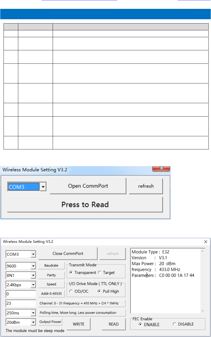
1 Install Driver Please install the USB adapter driver (CP2102).
2 Pull out the
jumper
Pull the M0、M1 jumper out, see figure 9
3.3V or 5V are available for jumper.
3 Connect to
module
Connect the module with USB adapter.
Connect to the USB interface of PC.
4 Open serial
port
Operate the parameter setting software, choose corresponding serial number and
press the “Open CommPort” button.
Please choose other serial numbers until open successfully.
5 Interface
Press“Press to Read”button,the interface will be as figure 9
If failed, please check if the module is in mode 3, or the driver has been installed or
not.
6 Input
parameter
Please adjust the parameter as your request according to the corresponding
setting, then click “Write” button, write the new parameter to the module
7 Complete the o
peration.
Please operate the “Fifth step” if you need to reconfigure,
if the configuration is completed,
Please click "close UART" and then take off the module.
8 Commands
Configuration Parameter configuration is also available for MCU (in mode 3).
434MHz

E32-TTL-100 Datasheet V1.0 Chengdu Ebyte Electronic Technology Co., Ltd.
Purchase the sample:http://www.aliexpress.com/store/2077046 Website: www.cdebyte.com
Professional R&D RF Module 2.4G、915M、868M、780M、490M、434M、315M、230M、170M Wireless Module
Page 14 of 14 The copyright and the product has the Chengdu Ebyte Electronic Technology Co., Ltd. All
FCC Statement
This device complies with part 15 of the FCC Rules. Operation is subject to the following two conditions: (1) This device may not cause harmful
interference, and (2) this device must accept any interference received, including interference that may cause undesired operation.
Changes or modifications not expressly approved by the party responsible for compliance could void the user's authority to operate the
equipment.
NOTE: This equipment has been tested and found to comply with the limits for a Class B digital device, pursuant to Part 15 of the FCC Rules.
These limits are designed to provide reasonable protection against harmful interference in a residential installation. This equipment generates,
uses and can radiate radio frequency energy and, if not installed and used in accordance with the instructions, may cause harmful interference to
radio communications. However, there is no guarantee that interference will not occur in a particular installation. If this equipment does cause
harmful interference to radio or television reception, which can be determined by turning the equipment off and on, the user is encouraged to try
to correct the interference by one or more of the following
measures:
-- Reorient or relocate the receiving antenna.
-- Increase the separation between the equipment and receiver.
-- Connect the equipment into an outlet on a circuit different from that to which the receiver is connected.
-- Consult the dealer or an experienced radio/TV technician for help.
FCC Radiation Exposure Statement
This modular complies with FCC RF radiation exposure limits set forth for an uncontrolled environment. This transmitter must not be co-located
or operating in conjunction with any other antenna or transmitter.
If the FCC identification number is not visible when the module is installed inside another device, then the outside of the device into which the
module is installed must also display a label referring to the enclosed module. This exterior label can use wording such as the following:
“Contains Transmitter Module FCC ID: 2ALPH-E32-TTL-100 Or Contains FCC ID: 2ALPH-E32-TTL-100”
when the module is installed inside another device, the user manual of this device must contain below warning statements;
1. This device complies with Part 15 of the FCC Rules. Operation is subject to the following two conditions:
(1) This device may not cause harmful interference.
(2) This device must accept any interference received, including interference that may cause undesired operation.
2. Changes or modifications not expressly approved by the party responsible for compliance could void the user's authority to operate the
equipment.
The devices must be installed and used in strict accordance with the manufacturer's instructions as described in the user documentation that
comes with the product
E32-TTL-100 Datasheet V1.0 Chengdu Ebyte Electronic Technology Co., Ltd.
Purchase the sample:http://www.aliexpress.com/store/2077046 Website: www.cdebyte.com
Professional R&D RF Module 2.4G、915M、868M、780M、490M、434M、315M、230M、170M Wireless Module
Page 15 of 14 The copyright and the product has the Chengdu Ebyte Electronic Technology Co., Ltd. All
.6.About us E32-TTL-100
Chengdu Ebyte Electronic Technology Co., Ltd is a high-tech company, focus on wireless transmission.
Our company owns a number of independent research & development products and obtain unanimously
approved customers. With powerful R&D team, our company can provide customers with perfect After-sales
service and technical assistance.
【Website】:www.cdebyte.com 1111 【Aliexpress】:http://www.aliexpress.com/store/2077046
【Address】: Innovation Center D347,4# XI-XIN road, High-tech district(West),Chengdu, Sichuan, China
【Contact person】:chenfang@cdebyte.com Elaine
【Contact person】:fanjuan@cdebyte.com Maggie
【Technical support】:support@cdebyte.com