Chengdu Vantron Technology VTM2MBTA-DE VT-M2M-BTA-DE User Manual
Chengdu Vantron Technology, Ltd. VT-M2M-BTA-DE
UserManual.wiki
>
Chengdu Vantron Technology
>
VTM2MBTA DE User Manual
User Manual
Navigation menu
Upload a User Manual
Namespaces
Wiki Guide
HTML
PDF
Info
Views
User Manual
Discussion / Help
Navigation
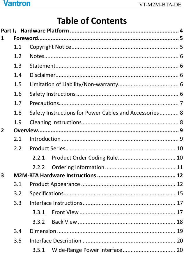

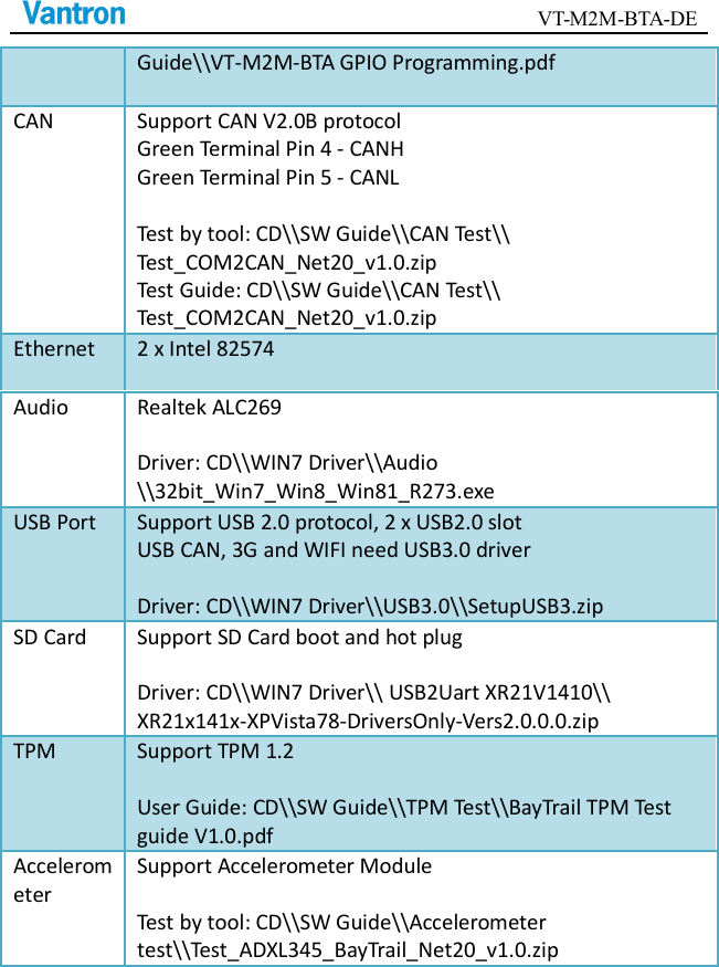
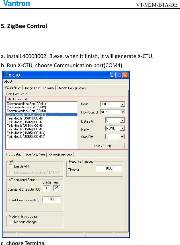
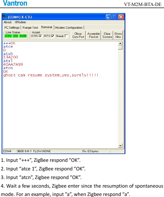
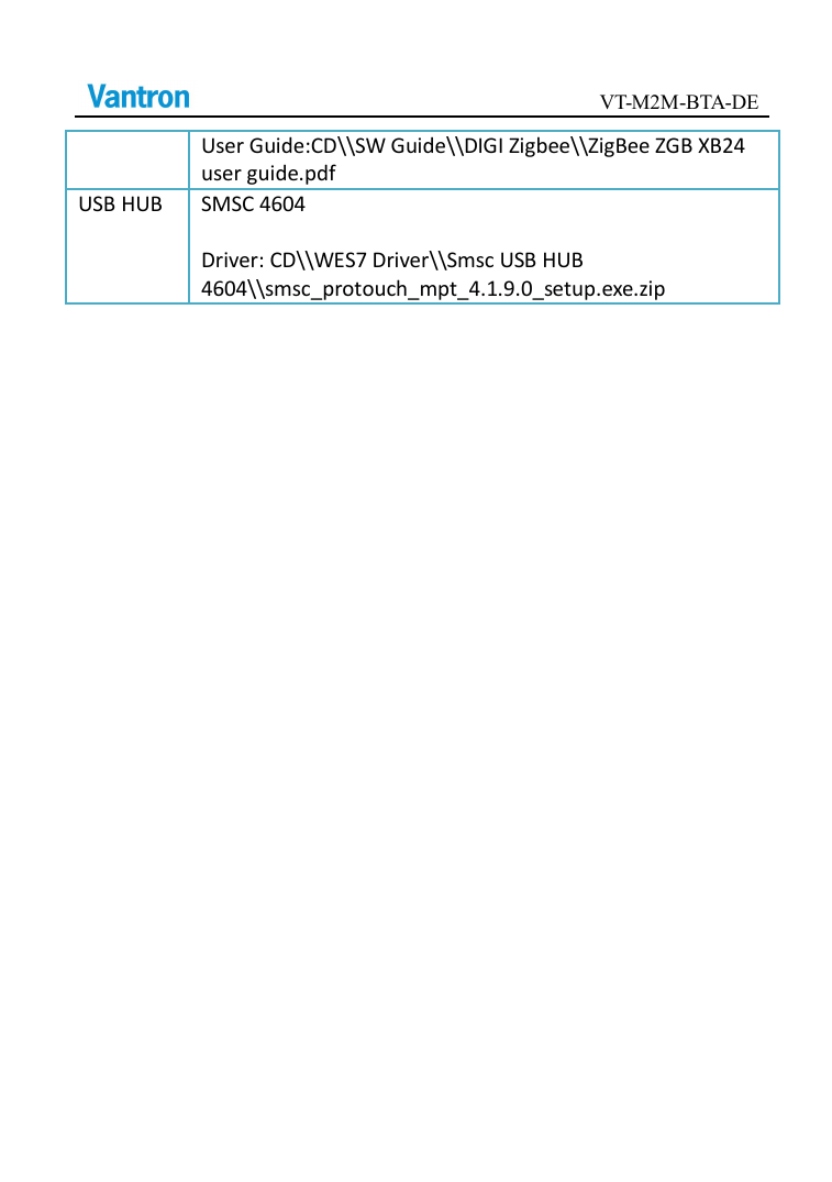
![VT-M2M-BTA-DE User Guide: CD\\SW Guide\\Accelerometer test\\Test_ADXL345_BayTrail_Net20_v1.0.zip WIFI Intel N62205 Driver: CD\\WIN7 Driver\\Intel WIFI 62205ANHMW\\intel_wireless_14.2.0.10_s64.exe 3G Telit HE910 User Guide: CD\\WIN7 Driver\\Telit HE910\\HE910 Use guide.pdf Driver: CD\\WIN7 Driver\\Telit HE910\\Telit_xE910_HE863_USB-Driver_Win_desktop_OS_U8.00.04.zip Telit DE910 User Guide: CD\\WIN7 Driver\\Telit DE910\\DE910 Use guide.pdf Driver: CD\\WIN7 Driver\\Telit DE910\\ Telit_UC_CC_DE_CE_USB_Driver_WinDesktop_2000_XP_Vista_Seven_U8_00_03.zip GPS Support GPS Module Test by tool: CD\\SW Guide\\GPS Test\\RCT-1[1].1.0BETA.exe User Guide: CD\\SW Guide\\GPS Test\\GPS user guide.pdf ZigBee Digi ZigBee Test by tool: CD\\SW Guide\\DIGI Zigbee\\40003002_B.exe](https://usermanual.wiki/Chengdu-Vantron-Technology/VTM2MBTA-DE/User-Guide-2563157-Page-35.png)
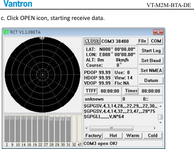
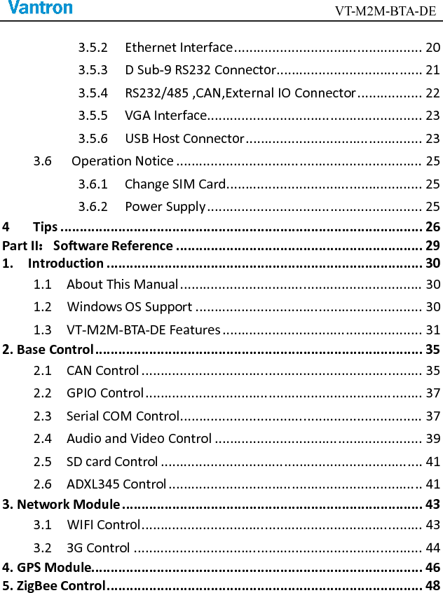
![VT-M2M-BTA-DE 4. GPS Module a. Click RCT-1[1].1.0BETA.exe, use the right key of the mouse, choose Run as administrator. b. Click COM icon, choose COM3, 38400.](https://usermanual.wiki/Chengdu-Vantron-Technology/VTM2MBTA-DE/User-Guide-2563157-Page-48.png)