Chengdu Vantron Technology VTM2MBTA-DE VT-M2M-BTA-DE User Manual
Chengdu Vantron Technology, Ltd. VT-M2M-BTA-DE
User Manual
All Rights Reserved
VT-M2M-BTA-DE
User’s Manual
Vantron Technology
www.vantrontech.com

VT-M2M-BTA-DE
Revision History:
No.
Version
Description
Date
1
V1.0
First release
June
.1
7
, 201
4
2
V1.1
Modify description of COM
June
.
23, 2014
3
V1.2
Add
software part
D
ecember 18, 2014
4 V1.3
1.
Update the
safety
Instructions
2. Add antenna description Feb 11,2015

VT-M2M-BTA-DE
Table of Contents
Part I:Hardware Platform .................................................................... 4
1 Foreword........................................................................................ 5
1.1 Copyright Notice ................................................................... 5
1.2 Notes .................................................................................... 6
1.3 Statement ............................................................................. 6
1.4 Disclaimer............................................................................. 6
1.5 Limitation of Liability/Non-warranty...................................... 6
1.6 Safety Instructions ................................................................ 6
1.7 Precautions........................................................................... 7
1.8 Safety Instructions for Power Cables and Accessories ............ 8
1.9 Cleaning Instructions ............................................................ 8
2 Overview ........................................................................................ 9
2.1 Introduction ......................................................................... 9
2.2 Product Series..................................................................... 10
2.2.1 Product Order Coding Rule .................................... 10
2.2.2 Ordering Information ............................................ 11
3 M2M-BTA Hardware Instructions ................................................. 12
3.1 Product Appearance ........................................................... 12
3.2 Specifications...................................................................... 15
3.3 Interface Instructions .......................................................... 17
3.3.1 Front View ............................................................ 17
3.3.2 Back View ............................................................. 18
3.4 Dimension .......................................................................... 19
3.5 Interface Description .......................................................... 20
3.5.1 Wide-Range Power Interface ................................. 20

VT-M2M-BTA-DE
3.5.2 Ethernet Interface ................................................. 20
3.5.3 D Sub-9 RS232 Connector...................................... 21
3.5.4 RS232/485 ,CAN,External IO Connector ................. 22
3.5.5 VGA Interface........................................................ 23
3.5.6 USB Host Connector .............................................. 23
3.6 Operation Notice ................................................................ 25
3.6.1 Change SIM Card ................................................... 25
3.6.2 Power Supply ........................................................ 25
4 Tips .............................................................................................. 26
Part II:Software Reference ................................................................ 29
1. Introduction .................................................................................. 30
1.1 About This Manual ............................................................... 30
1.2 Windows OS Support ........................................................... 30
1.3 VT-M2M-BTA-DE Features .................................................... 31
2. Base Control ..................................................................................... 35
2.1 CAN Control ......................................................................... 35
2.2 GPIO Control ........................................................................ 37
2.3 Serial COM Control ............................................................... 37
2.4 Audio and Video Control ...................................................... 39
2.5 SD card Control .................................................................... 41
2.6 ADXL345 Control .................................................................. 41
3. Network Module .............................................................................. 43
3.1 WIFI Control ......................................................................... 43
3.2 3G Control ........................................................................... 44
4. GPS Module...................................................................................... 46
5. ZigBee Control .................................................................................. 48

VT-M2M-BTA-DE

VT-M2M-BTA-DE
Part I:Hardware Platform

VT-M2M-BTA-DE
1 Foreword
1.1 Copyright Notice
While all information contained herein have been carefully checked
to assure its accuracy in technical details and printing, Vantron assumes
no responsibility resulting from any error or features of this manual, or
from improper uses of this manual or the software. Please contact our
technical department for relevant operation solutions if there is any
problem that cannot be solved according to this manual.
Vantron reserves all rights of this manual, including the right to
change the content, form, product features, and specifications
contained herein at any time without prior notice. The latest version of
this manual is at www.vantrontech.com.cn. Please contact Vantron for
further information:
Vantron Technology(Vantron)
E-mail: sales@vantrontech.com
The trademarks and registered trademarks in this manual are properties
of their respective owners. No part of this manual may be copied,
reproduced, translated or sold. No changes or other purposes are
permitted without the prior written consent of Vantron.
Vantron reserves the right of all publicly-released copies of this
manual.
VT-M2M-BTA-DE
1.2 Notes
Applicable notes are listed in the following table:
Sign
Notice Type
Description
Notice Important information and regulations
Caution Caution for latent damage to system or harm
to personnel
1.3 Statement
It is recommended to read and comply with this manual before
operating VT-M2M-BTA which provides important guidance and helps
decreasing the danger of injury, electric shock, fire, or any damage to
the device.
1.4 Disclaimer
Vantron assumes no legal liability of accidents resulting from failure of
conforming to the safety instructions.
1.5 Limitation of Liability/Non-warranty
For direct or indirect damage to this device or other devices of
Vantron caused by failure of conforming to this manual or the safety
instructions on device label, Vantron assumes neither warranty nor legal
liability even if the device is still under warranty.
1.6 Safety Instructions
Keep and comply with all operation instructions, warnings, and

VT-M2M-BTA-DE
information.
Pay attention to warnings on this device.
Read the following precautions so as to decrease the danger of
injury, electric shock, fire, or any damage to the device.
Operations and Service instructions are provided with the
equipment.
Unit shall be used with indoor-use antenna only. No antenna for this
unit can be installed outdoor.
The maximum operation temperature is 61°C.
1.7 Precautions
Pay attention to the product labels/safety instructions printed on
silk screens.
Do not try repairing this product unless declared in this manual.
Keep away from heat source, such as heater, heat dissipater, or
engine casing.
Do not insert other items into the slot (if any) of this device.
• Keep the ventilation slot ventilated for cooling.
•System fault may arise if other items are inserted into this device.
Installation: ensure correct installation according to instructions
from the manufacturer with recommended installation tools.
Ensure ventilation and smoothness according to relevant ventilation
standard.
VT-M2M-BTA-DE
1.8 Safety Instructions for Power Cables and Accessories
Proper power source only Start only with power source that
satisfies voltage label and the voltage necessary according to this
manual. Please contact technical support personnel of Vantron for any
uncertainty about the requirements of necessary power source.
Use tested power source This product still contains a button
lithium battery as a real-time clock after its external power source is
removed and therefore should not be short-circuited during
transportation or placed under high temperature.
Place cables properly: Do not place cables at any place with
extrusion danger.
1.9 Cleaning Instructions
Please power off before cleaning the device.
Do not use spray detergent.
Clean with a damp cloth.
Do not try cleaning exposed electronic components unless with a
dust collector.
Support for special fault: Power off and contact technical support
personnel of Vantron in case of the following faults:
The device is damaged.
The temperature is excessively high.
Fault is still not solved after the operation according to the
manual.

VT-M2M-BTA-DE
2 Overview
2.1 Introduction
Thank you for choosing Vantron. It is our commitment to provide our
valued customers with the embedded devices equipped with the
state-of-the-art technology and the best product services.
Vantron’s M2M products are based on the most advanced ARM and
Intel Atom processors and have low-power consumption and high
integration. The products are designed for applications of M2M in
industrials, medicals, financial, retail, vehicle, and transportations etc.
VT-M2M-BTA-DE
2.2 Product Series
2.2.1 Product Order Coding Rule
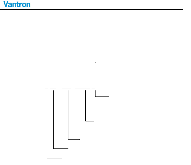
Order Code
VT-M2M-BTA-DE-S-1GM-16GF-GWZP-V
Version:
I: Extended Temperature
Blank:Commercial temperature
Wireless Module Option:
2G: 2G, 3G: 3G, W: WiFi, Z: Zigbee, P: GPS
SD Memory Size: 16G: 16GB
DDR Memory Size:
1G:
1G
B
, 2G: 2GB
CPU Speed: S/D/Q:Single / Dual/ Quad
VT-M2M-BTA-DE
2.2.2 Ordering Information
Order Examples:
VT-M2M-BTA-DE-S-1GM-16GF-G
WP-I
ATOM Baytrail single Processor, 1GB DDR3L, 16GB SSD, 3G, WiFi,
GPS, extended temperature
VT-M2M-BTA-DE-Q-1GM-16GF-W
P
ATOM Baytrail quad Processor, 1GB DDR3L, 16G SSD, WiFi, GPS,
commercial temperature
Accessories:
Install Mechanical tools,1pc
Power Adapter with locked connector (Optional),1pc
IO Terminal (12x3.81mm) (Optional),1pc
3G Antenna(Optional),1pc
WiFi Antenna(Optional),1pc
Zigbee Antenna(Optional),1pc
GPS Antenna(Optional),1pc
VT-M2M-BTA-DE
3 M2M-BTA Hardware Instructions
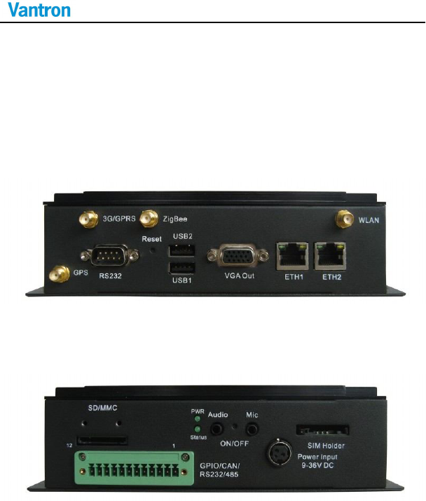
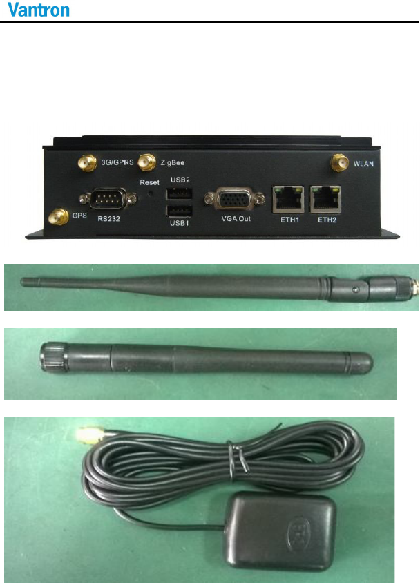
3.1 Product Appearance
Front Side View
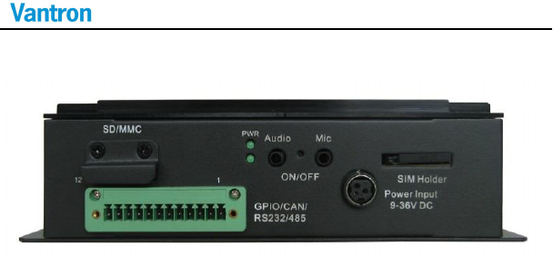
Back Side View
VT-M2M-BTA-DE
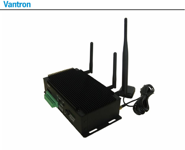
View for all optional embedded modules and antennas
VT-M2M-BTA-DE
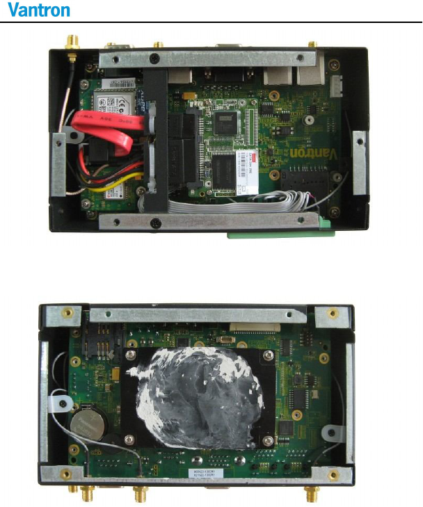
Bottom View for optional embedded modules
(1xHalf PCIe slot under the 1xPCIe slot)
Top View for thermal module

VT-M2M-BTA-DE
3.2 Specifications
Specifications
CPU Processor Intel® ATOM™, E3827/1.75GHz, E3845/1.91GHz,
E3815/1.46GHz
Memory On Board
RAM
On Board DDRIII 1333MT/s(E3845&E3827)/ 1066MT/s
(E3815), up to 2GB
ROM Internal
1.8”SATA SSD Module Internal (16GB, or others)
On board SATA2.0 SSD 8GB(OPTIONAL)
Display Chipset Support LVDS/HDMI/VGA, simultaneous/dual view
display
Resolution Up to 1280 x 768 @ 60Hz for LVDS;
Up to 1920x1200@60Hz for HDMI
Up to
2560x1600@60
Hz for VGA
Interface 1xVGA (DB15)
1xLVDS (Optional Internal)
Wireless
Communication
WLAN Optional 802.11 b/g/n Wireless Module, external
antenna , Support 1x Half PCIe Wireless card
3G Module Optional1x mini PCIe 3G Broad Band Module with SIM
slot
ZigBee Optional low power Zigbee Module, external antenna
GPS Optional GPS module, external antenna
Peripheral
Interfaces
Ethernet 1x10/100/1000-BaseT(RJ45)
USB 2xUSB2.0 Host (Type A)
Audio HD Audio, 1xMIC in 3.5mm, 1xline Out
3
.
5
mm
(
optional
)
COM Port 1xRS232/485/422(DB9 full function),
1xRS232/485(2 wires on Green Terminal)

VT-M2M-BTA-DE
Alarm Buzzer Out
SD card 1xSD card Slot (Optional )
RTC Supported
Control Reset Button in the front,Power button in the back
GPIO Reserved GPIO (Terminal)
CAN 1x CAN2.0b
Security security On board Registration Serial Number, and SHA-1
Encrypt/Decrypt Chip DS28E01 (Optional)
TPM on board
Software OS Windows, or Linux
Applications SDK Available
Power Input DC9-36V(default 12V), Locked Power Jack
Consumption
6W (Pulse8W), Sleep 2W. (without
3G,GPS,Zigbee,WLAN)
Mechanical Dimensions 176x101x52mm (Box)
Install 198x101x52mm
Weight 0.6Kg (1.2KKg package Kit)
Enclosure Aluminum Alloy with Black Color
Environment
Condition
Temperature Operating:-0°C ~ +65°C
( ETR:-40°C ~ +65°C Optional)
Storage: -20°C ~ +70°C,
(ETR:-40°C ~ +85°C Optional)
Humidity 5-95%RH at 25-35 (Non-Condensation)
Cooling Mode
Fan less, Heat Sink
Approvals UL, FCC Class B, and CE
VT-M2M-BTA-DE
3.3 Interface Instructions
3.3.1 Front View
3G / GPRS Antenna(3G Band) Antenna Gain:1dBi
WLAN / ZigBee Antenna(2.4G Band) Antenna Gain:3.2dBi
GPS Antenna(1.5G Band)
VT-M2M-BTA-DE
3.3.2 Back View
VT-M2M-BTA-DE
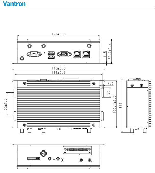
3.4 Dimension
VT-M2M-BTA-DE
3.5 Interface Description
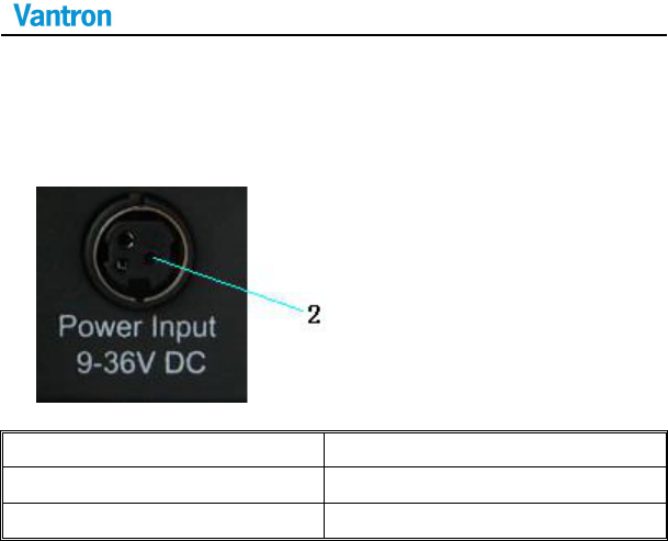
3.5.1 Wide-Range Power Interface
Power JACK with lock
Pin
Description
1,3 DGND (ground pin)
2 Power (+12 DC,UP to 36V)
3.5.2 Ethernet Interface
Standard RJ45 interface, supporting 10M/100M/1000M
self-adaptation, this is a standard RJ45 ethernet port
VT-M2M-BTA-DE
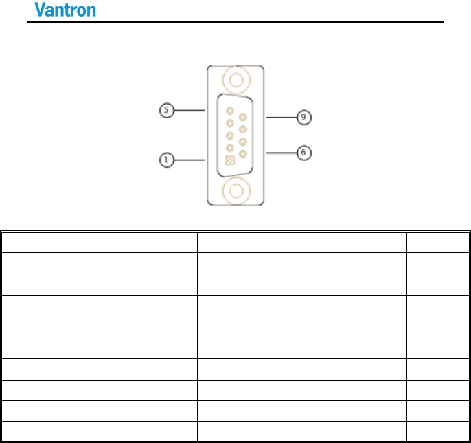
3.5.3 D Sub-9 RS232 Connector
Standard vertical DB-9 male connector
Pin Description
Remarks
1 DCD1/422TX+/485_A
BIOS set
2 RXD1/422TX-/485_B
B
IOS set
3 TXD1/422RX+
BIOS set
4 DTR1/422RX-
BIOS set
5 DGND (ground pin)
6 DSR1
7 RTS1
8 CTS1
9 RI1
VT-M2M-BTA-DE
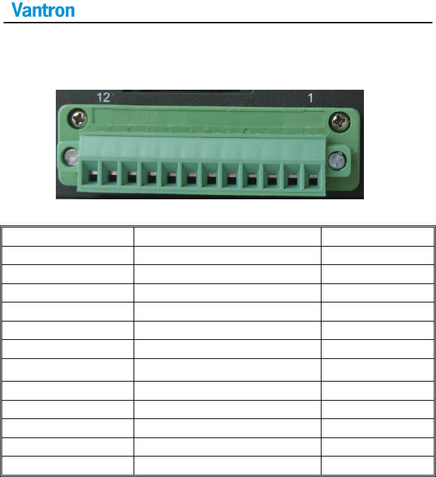
3.5.4 RS232/485 ,CAN,External IO Connector
12pins 3.81 pitch terminal with screw lock
Load capacity: more than 128 nodes/RS485 channel
Pin
Description
Remarks
1 TXD2/485_2_A
BIOS set
2 RXD2/485_2_B
BIOS set
3 DGND
4 CANH
5 CANL
6 DGND
7 EXTIO0
3.3V Level
8 EXTIO1
3.3V Level
9 EXTIO2
3.3V Level
10 EXTIO3
3.3V Level
11 EXTIO4
3.3V Level
12 EXTIO5
3.3V Level
VT-M2M-BTA-DE
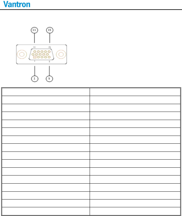
3.5.5 VGA Interface
Standard vertical DB-15 Female VGA connector
Pin Description
1 RED
2 GREEN
3 BLUE
4 N.C.
5 GND
6 GND
7 GND
8 GND
9 +5VDC
10 GND
11 N.C.
12 SD_DDC
13 HSYNC
14 VHYNC
15 SC_DDC
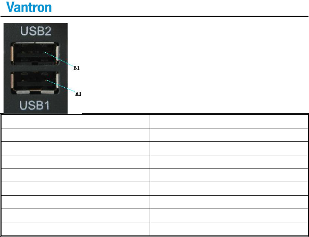
3.5.6 USB Host Connector
Dual vertical USB A type interface, USB2.0
VT-M2M-BTA-DE
Pin
Description
A1
USB1_VCC(+5VDC)
A2
USB1_D
-
A3
USB1_D+
A4
USB1_DGND(ground pin)
B1
USB2_VCC(+5VDC)
B2
USB2_D
-
B3
USB2_D+
B4
USB2_DGND(ground pin)

VT-M2M-BTA-DE
3.6 Operation Notice
3.6.1 Change SIM Card
Push the small button on the left of SIM Card Holder, and install the SIM
card to the holder. Then push the holder into the Slot.
3.6.2 Power Supply
Please make sure using adapter in the accessory, or the power is not
reversed when powered by other adapter.
VT-M2M-BTA-DE
4 Tips
Waste Disposal
It is recommended to disassemble the device before abandoning it in
conformity with local regulations. Please ensure that the abandoned
batteries are disposed according to local regulations on waste disposal.
Do not throw batteries into fire (explosive) or put in common waste
canister. Products or product packages with the sign of “explosive”
should not be disposed like household waste but delivered to
specialized electrical &electronic waste recycling/disposal center.
Proper disposal of this sort of waste helps avoiding harm and adverse
effect upon surroundings and people’s health. Please contact local
organizations or recycling/disposal center for more recycling/disposal
methods of related products.
Comply with the following safety tips:
Do not use in combustible and explosive environment
Keep away from combustible and explosive environment for fear of
danger.
VT-M2M-BTA-DE
Keep away from all energized circuits.
Operators should not remove enclosure from the device. Only the
group or person with factory certification is permitted to open the
enclosure to adjust and replace the structure and components of the
device. Do not change components unless the power cord is removed.
In some cases, the device may still have residual voltage even if the
power cord is removed. Therefore, it is a must to remove and fully
discharge the device before contact so as to avoid injury.
Unauthorized changes to this product or its components are
prohibited.
In the aim of avoiding accidents as far as possible, it is not allowed to
replace the system or change components unless with permission and
certification. Please contact the technical department of Vantron or
local branches for help.
Pay attention to caution signs.
Caution signs in this manual remind of possible danger. Please comply
with relevant safety tips below each sign. Meanwhile, you should strictly
conform to all safety tips for operation environment.
VT-M2M-BTA-DE
Notice
Considering that reasonable efforts have been made to assure
accuracy of this manual, Vantron assumes no responsibility of possible
missing contents and information, errors in contents, citations,
examples, and source programs.
Vantron reserves the right to make necessary changes to this manual
without prior notice. No part of this manual may be reprinted or publicly
released in forms of photocopy, tape, broadcast, e-document, etc.
RF exposure warning
This equipment must be installed and operated in accordance with
provide instructions and the antenna used for this transmitter must be
installed to provide a separation distance of at least 20 cm from all
persons and must not be co-located or operation in conjunction with
any other antenna or transmitter. End-users and installers must be
provide with antenna installation instructions and transmitter operating
conditions for satisfying RF exposure compliance.

VT-M2M-BTA-DE
Part II:Software Reference

VT-M2M-BTA-DE
1. Introduction
Thank you for choosing Vantron. It is our commitment to provide our
valued customers with the embedded devices equipped with the state of
the art technology and the best product services.
Vantron’s M2M products are based on the most advanced ARM and
Intel Atom processors and have low power consumption and high
integration. The products are designed for applications of M2M in
industrials, medicals, financial, retail, vehicle, and transportations etc.
1.1 About This Manual
This manual is for user how to configure and use devices in Windows
system.
1.2 Windows OS Support
The VT-M2M-BTA-DE supports the following Windows operating systems.
Windows* Embedded Standard 7 64 bit (WES7)
Windows* 7 32bit / 64bit
Windows* 8 32bit / 64bit
Windows* Embedded Standard 8 64 bit (WES8)

VT-M2M-BTA-DE
1.3 VT-M2M-BTA-DE Features
The below table lists VT-M2M-BTA-DE features.
Device
Name
Description
VGA
M
aximum resolution up to 2560x1600
@
60 Hz
Driver: CD\\WIN7 Driver\\Graphic\\
Intel_EMGD.WIN7_PC_Version_36_15_0_1073.7z
COM
Ports
COM1~5 default RS232
COM1 : DB9, support RS232/RS422/RS485, baud rate up to
115200bps
COM2 : Green terminal pin 1 and 2, support RS232/RS485
Baud rate up to 115200bps
COM3 : GPS
COM4 : ZigBee
COM5 : null
Configure by BIOS option:
Device Management >> SIO SCH3114 Serial Port x
Device Management >> SIO FINTEK81801U Serial Port x
Test by tool : CD\\SW Guide\\COM Test\\TestCommPC
V2.3.3.exe
GPIO
EXTIO 0 ~ 5
Green terminal pin 7 to 12
Configure by BIOS option:
Advanced >> Onboard Devices Configuration >> GPIO
Configguration
Programming Guide: CD\\SW Guide\\GPIO

VT-M2M-BTA-DE
Guide
\
\
VT
-
M2M
-
BTA GPIO Programming.pdf
CAN
Support CAN V2.0B protocol
Green Terminal Pin 4 - CANH
Green Terminal Pin 5 - CANL
Test by tool: CD\\SW Guide\\CAN Test\\
Test_COM2CAN_Net20_v1.0.zip
Test Guide: CD\\SW Guide\\CAN Test\\
Test_COM2CAN_Net20_v1.0.zip
Ethernet
2
x Intel 82574
Audio
Realtek ALC269
Driver: CD\\WIN7 Driver\\Audio
\\32bit_Win7_Win8_Win81_R273.exe
USB Port
Support USB 2.0 protocol, 2 x
USB2.0 slot
USB CAN, 3G and WIFI need USB3.0 driver
Driver: CD\\WIN7 Driver\\USB3.0\\SetupUSB3.zip
SD Card
Support SD Card boot and hot plug
Driver: CD\\WIN7 Driver\\ USB2Uart XR21V1410\\
XR21x141x-XPVista78-DriversOnly-Vers2.0.0.0.zip
TPM
Support TPM
1.2
User Guide: CD\\SW Guide\\TPM Test\\BayTrail TPM Test
guide V1.0.pdf
Accelerom
eter
Support Accelerometer Module
Test by tool: CD\\SW Guide\\Accelerometer
test\\Test_ADXL345_BayTrail_Net20_v1.0.zip

VT-M2M-BTA-DE
User Guide:
CD
\
\
SW Guide
\
\
Accelerometer
test\\Test_ADXL345_BayTrail_Net20_v1.0.zip
WIFI
Intel N62205
Driver: CD\\WIN7 Driver\\Intel WIFI
62205ANHMW\\intel_wireless_14.2.0.10_s64.exe
3G
Telit HE910
User Guide: CD\\WIN7 Driver\\Telit HE910\\HE910 Use
guide.pdf
Driver: CD\\WIN7 Driver\\Telit
HE910\\Telit_xE910_HE863_USB-Driver_Win_desktop_OS_
U8.00.04.zip
Telit DE910
User Guide: CD\\WIN7 Driver\\Telit DE910\\DE910 Use
guide.pdf
Driver: CD\\WIN7 Driver\\Telit DE910\\
Telit_UC_CC_DE_CE_USB_Driver_WinDesktop_2000_XP_Vis
ta_Seven_U8_00_03.zip
GPS
Support GP
S Module
Test by tool: CD\\SW Guide\\GPS
Test\\RCT-1[1].1.0BETA.exe
User Guide: CD\\SW Guide\\GPS Test\\GPS user guide.pdf
ZigBee
Digi ZigBee
Test by tool: CD\\SW Guide\\DIGI Zigbee\\40003002_B.exe

VT-M2M-BTA-DE
User Guide:CD
\
\
SW Guide
\
\
DIGI Zigbee
\
\
ZigBee ZGB XB24
user guide.pdf
USB HUB
SMSC 4604
Driver: CD\\WES7 Driver\\Smsc USB HUB
4604\\smsc_protouch_mpt_4.1.9.0_setup.exe.zip
VT-M2M-BTA-DE
2. Base Control
Turn on the product, boot to Windows.
2.1 CAN Control
This test application use to test COM2CAN communication, it support
32bits system. Please install Microsoft .Net 2.0 or above version and
USB2COM Driver in advance before run the application .
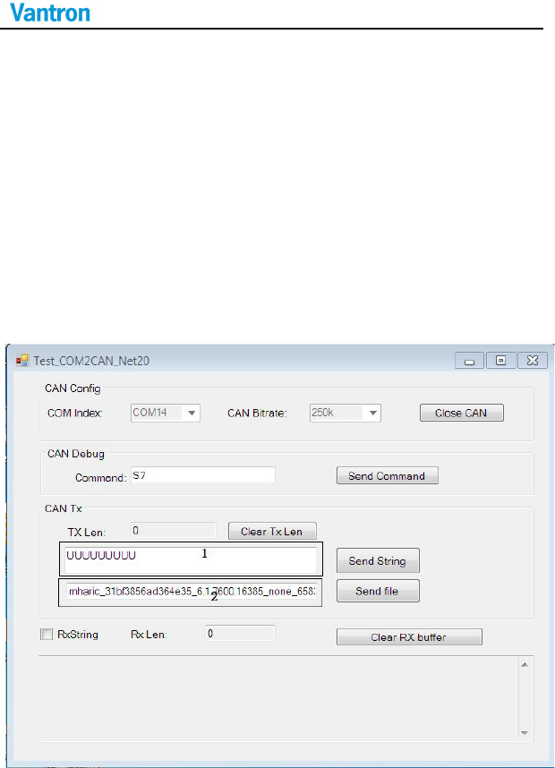
Application running as below:
VT-M2M-BTA-DE
Step Details:
1. Prepare 2 devices, and connect CAN.
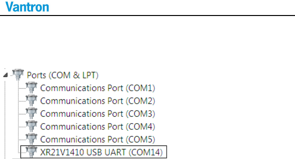
2. Enter windows7, look up COM number of USB2COM in device
manager.
3. According to the step2, select COM14 and set CAN speed to
500k(support 20k,50k,100k,125k,250k,500k,1M), Open device.
4. Input data in first TextBox in “CAN Tx” GroupBox, Click “Send String”
Button on one device, then “Tx Len” will record length of all data
sent( Click “Clear TxLen” to set TxLen = 0) .The target device will
receive data and show in TextBox in bottom of application now., If
we want show string ,Make “RxString” CheckBox checked. “Rx Len”
TextBox record length of receive data. Click “Clear Rx Buffer” button
will clear all receive data and set RxLen= 0.
5. Click “Send File” button to send file. Then file path will save to The
second TextBox in “CAN Tx” GroupBox.
6. We can achieve our all CAN function by “CAN Debug” Groupbox.
Open Channel: Input “O”, Click “Commit” button, If success, “0D”
returned.
Set CAN Bitrate: Input “C”, Click “Commit” button. Then input
“Sx”(0<=x<=8),Click “Commit” button. If success, “0D” returned.
Send Data: input “t000455555555”, If success, “0D” received.
The target device receive “uuuu”. The meaning of the sample
string explained in below:
VT-M2M-BTA-DE
t 000 4 55555555
Fixed value,
present send
data
ID, use 3
decimal
char
Send data
Length
Hexadecimal string,
Represent data “uuuu”
2.2 GPIO Control
Configure by BIOS option:
Advanced >> Onboard Devices Configuration >> GPIO Configguration
2.3 Serial COM Control
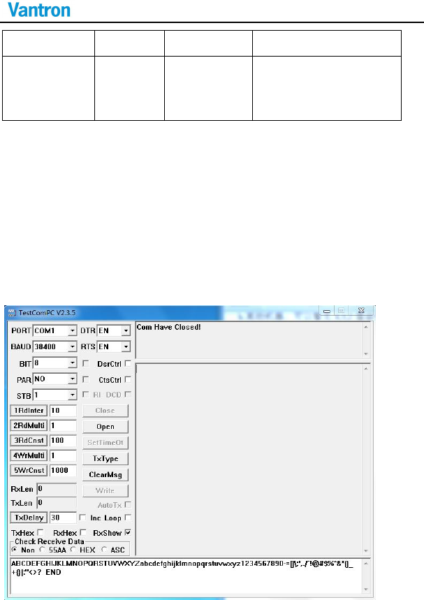
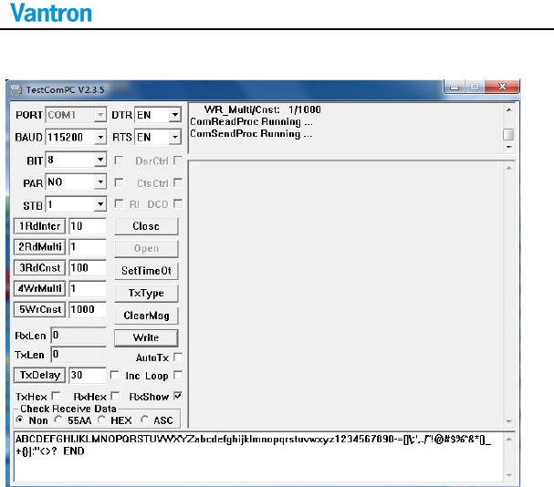
a. Run TestCommPC V2.3.3.exe
VT-M2M-BTA-DE
b. Select PORT COM1 or COM2, select BAUD 115200, click ”Open”.
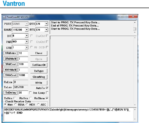
c. Click “AutoTx”, COM1 transmit the data below cyclically. If connect the
pin2 and pin3 of COM1, it will receive the data, and show on the right.
VT-M2M-BTA-DE
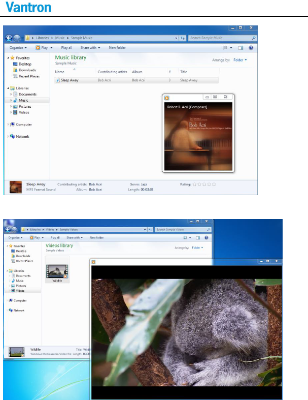
2.4 Audio and Video Control
a. It can play sample music.
VT-M2M-BTA-DE
b. It can play sample video.
VT-M2M-BTA-DE
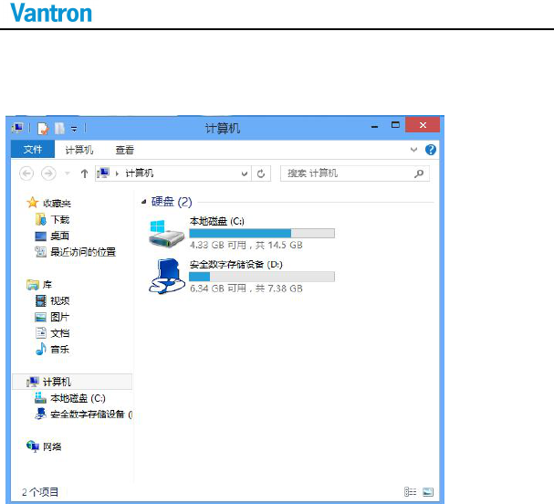
2.5 SD card Control
a. Insert SD card , then look over device:
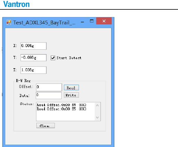
2.6 ADXL345 Control
a. Run Test_ADXL345_BayTrail_Net20.exe, click “start Detect”.
VT-M2M-BTA-DE
b. Shake the product, the value of X,Y,Z will change.
VT-M2M-BTA-DE
3. Network Module
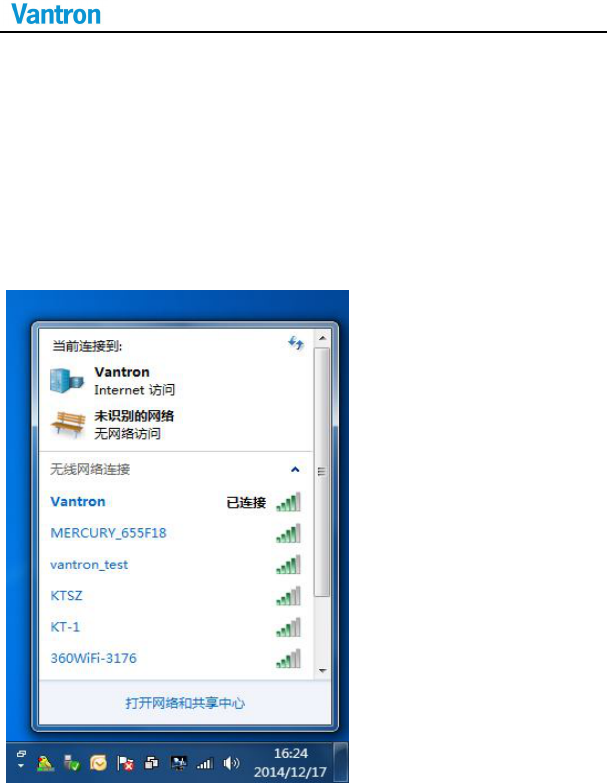
3.1 WIFI Control
a. Click the network icon, choose the WIFI, Enter the password, click the
OK icon.
VT-M2M-BTA-DE
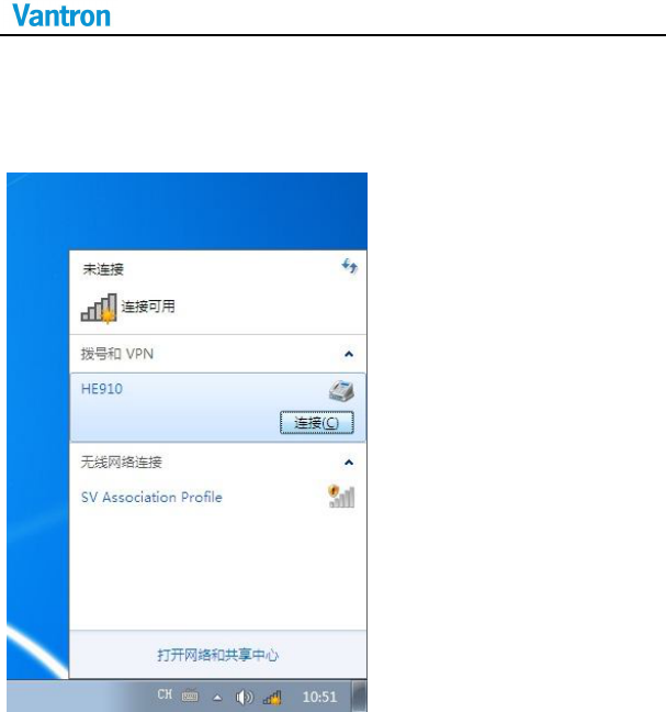
3.2 3G Control
HE910 only support WCDMA.
a. Click the network icon, choose the HE910, click the connect icon.
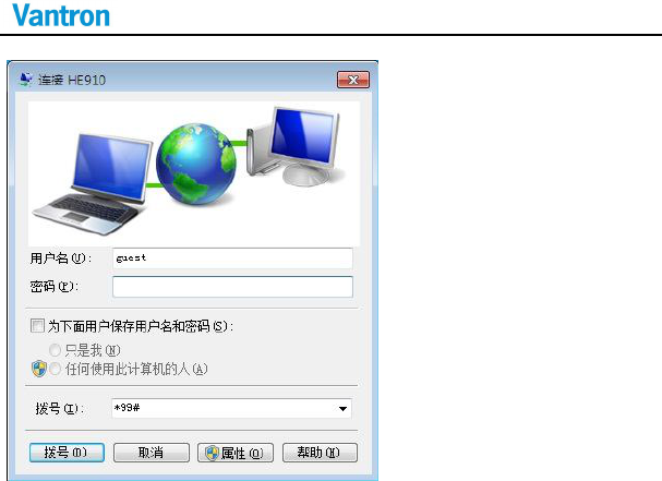
b. Click dial icon.
Tip: If it fail, try again.
VT-M2M-BTA-DE
DE910 only support CDMA2000.
a. Fill the Username: “card”, Password: “card”, Number: “#777”.
VT-M2M-BTA-DE
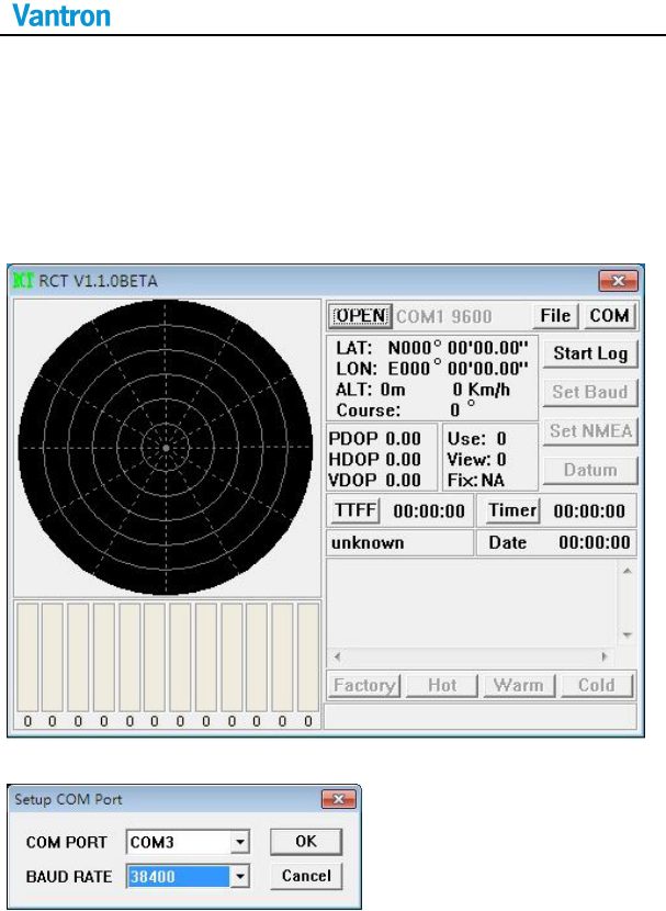
4. GPS Module
a. Click RCT-1[1].1.0BETA.exe, use the right key of the mouse, choose Run
as administrator.
b. Click COM icon, choose COM3, 38400.
VT-M2M-BTA-DE
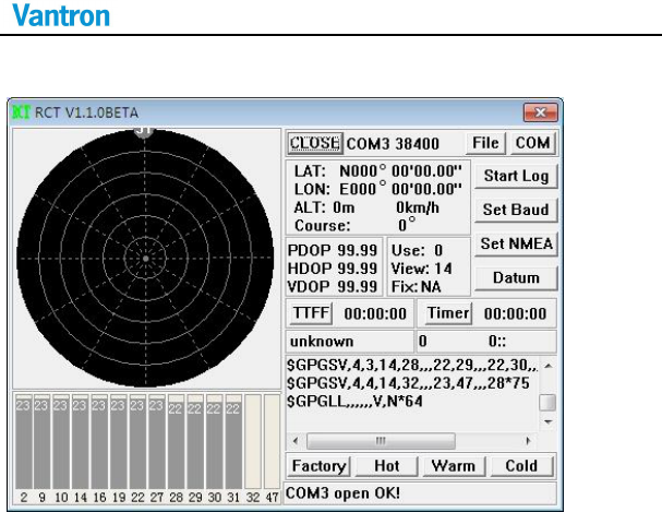
c. Click OPEN icon, starting receive data.
VT-M2M-BTA-DE
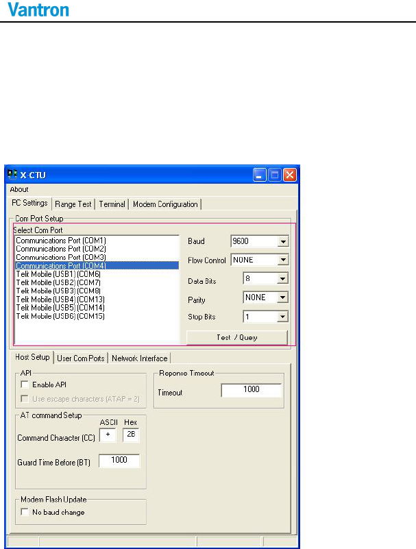
5. ZigBee Control
a. Install 40003002_B.exe, when it finish, it will generate X-CTU.
b. Run X-CTU, choose Communication port(COM4).
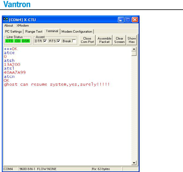
c. choose Terminal
VT-M2M-BTA-DE
1. Input “+++”, ZigBee respond “OK”.
2. Input “atce 1”, ZigBee respond “OK”.
3. Input “atcn”, Zigbee respond “OK”.
4. Wait a few seconds, Zigbee enter since the resumption of spontaneous
mode. For an example, input ”a”, when Zigbee respond “a”.

VT-M2M-BTA-DE
US Office: Vantron Technology, Inc.
Address: 1292 Kifer Road #807,
Sunnyvale, CA 94086
Tel: 510-304-7666
Email: sales@vantrontech.com
China Office: Chengdu Vantron Technology,Ltd
Address: 3rd floor, 3rd building, No.9, 3rd WuKe East Street, WuHou District,
Chengdu, P.R. China 610045
Tel: 86-28-8512-3930/3931, 8515-7572/6320
Email: sales@vantrontech.com.cn