Chief Manufacturing Pcm Series Users Manual INSTALLATION INSTRUCTIONS
PCM Series to the manual ae6a0748-943d-4c50-997b-6078c1153455
2015-02-05
: Chief-Manufacturing Chief-Manufacturing-Pcm-Series-Users-Manual-534979 chief-manufacturing-pcm-series-users-manual-534979 chief-manufacturing pdf
Open the PDF directly: View PDF ![]() .
.
Page Count: 8
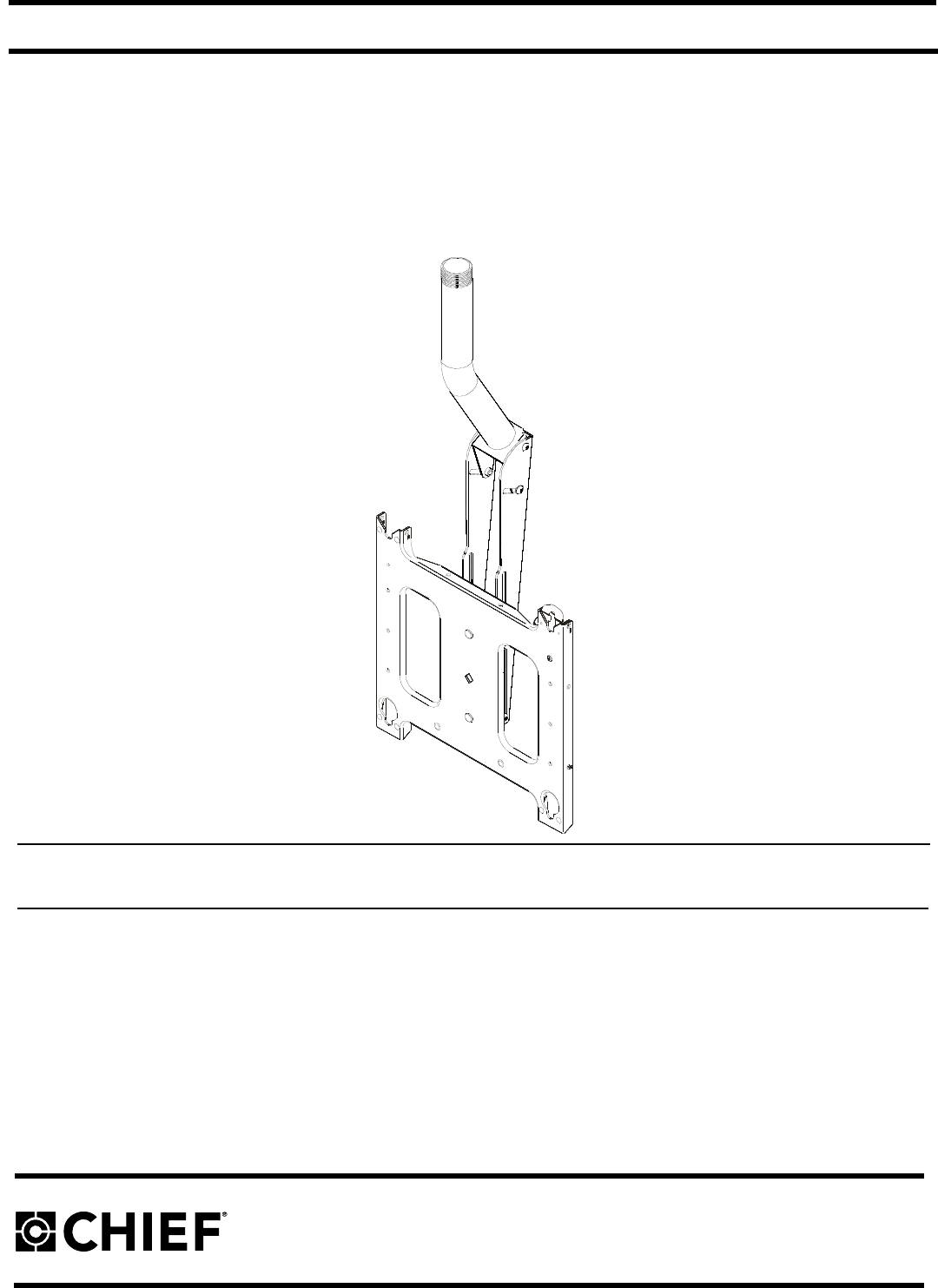
INSTALLATION INSTRUCTIONS
Instrucciones de instalación
Installationsanleitung
Instruções de Instalação
Istruzioni di installazione
Installatie-instructies
Instructions d´installation
Plasma Ceiling Mount
Spanish Product Description
German Product Description
Portuguese Product Description
Italian Product Description
Dutch Product Description
French Product Description
PCM SERIES
PCM SERIES Installation Instructions
2
DISCLAIMER
Milestone AV Technologies, Inc., and its affiliated corporations
and subsidiaries (collectively, "Milestone"), intend to make this
manual accurate and complete. However, Milestone makes no
claim that the information contained herein covers all details,
conditions or variations, nor does it provide for every possible
contingency in connection with the installation or use of this
product. The information contained in this document is subject to
change without notice or obligation of any kind. Milestone makes
no representation of warranty, expressed or implied, regarding
the information contained herein. Milestone assumes no
responsibility for accuracy, completeness or sufficiency of the
information contained in this document.
IMPORTANT WARNINGS AND
CAUTIONS!
WARNING:
A WARNING alerts you to the possibility of
serious injury or death if you do not follow the instructions.
CAUTION:
A CAUTION alerts you to the possibility of
damage or destruction of equipment if you do not follow the
corresponding instructions.
WARNING:
Failure to read, thoroughly understand, and
follow all instructions can result in serious personal injury,
damage to equipment, or voiding of factory warranty! It is the
installer’s responsibility to make sure all components are
properly assembled and installed using the instructions
provided.
WARNING:
Failure to provide adequate structural strength
for the installation of this kit can result in serious personal
injury or damage to equipment! It is the installer’s
responsibility to make sure the structure to which this mount is
attached can support five times the combined weight of all
equipment.
WARNING:
Exceeding the weight capacity can result in
serious personal injury or damage to equipment! It is the
installer’s responsibility to make sure the combined weight of
all components attached to this mount does not exceed
200 lbs (91 kg).
WARNING:
The installer is responsible for verifying that the
1 1/2” NPT fixture this mount is installed on is capable of
supporting four times the maximum weight capacity of the
mount as stated above.
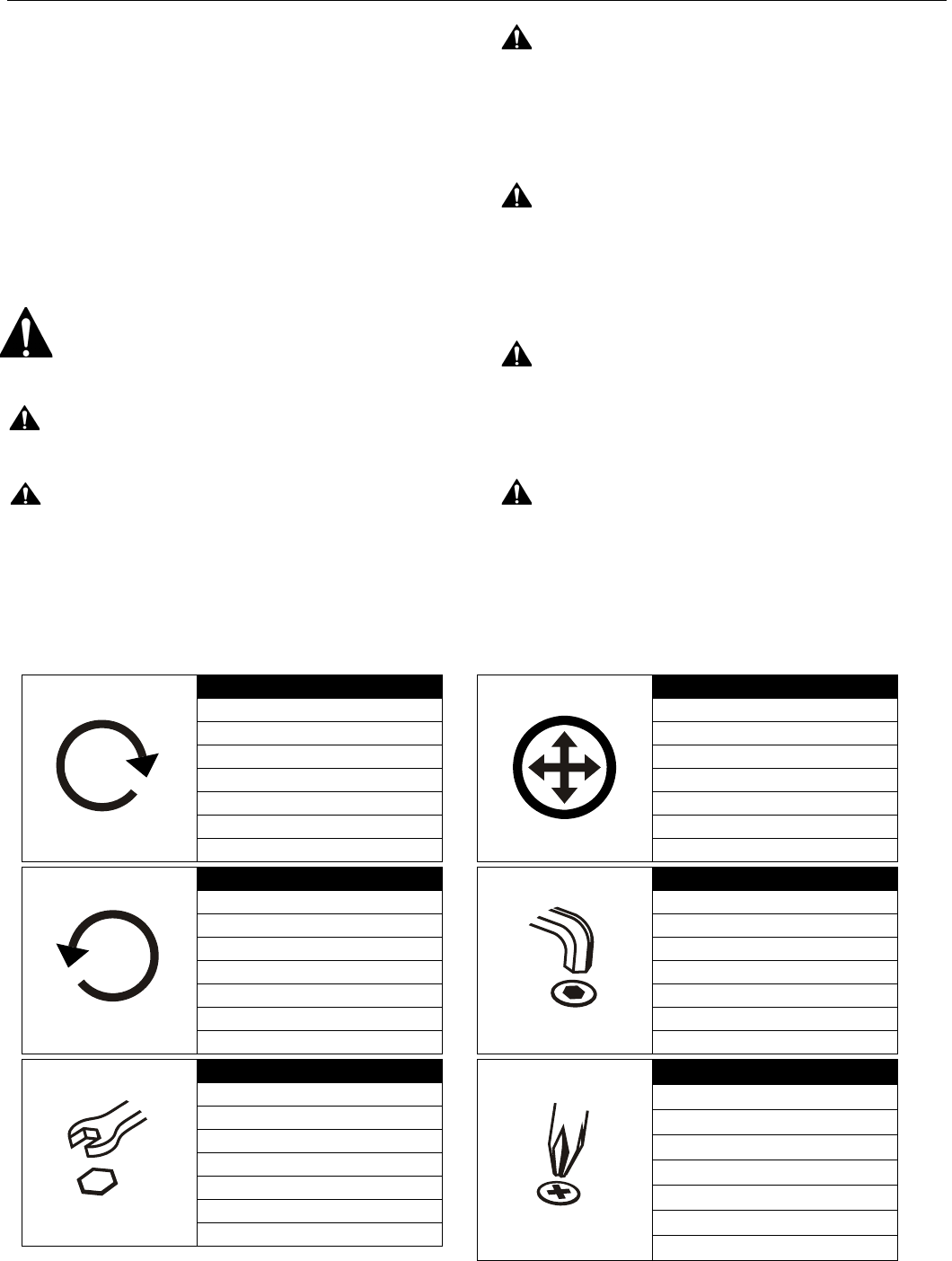
LEGEND
Tighten Fastener
Apretar elemento de fijación
Befestigungsteil festziehen
Apertar fixador
Serrare il fissaggio
Bevestiging vastdraaien
Serrez les fixations
Сожмите Застежку
Loosen Fastener
Aflojar elemento de fijación
Befestigungsteil lösen
Desapertar fixador
Allentare il fissaggio
Bevestiging losdraaien
Desserrez les fixations
Ослабьте Застежку
Open-Ended Wrench
Llave de boca
Gabelschlüssel
Chave de bocas
Chiave a punte aperte
Steeksleutel
Clé à fourche
Открытый Рывок
Adjust
Ajustar
Einstellen
Ajustar
Regolare
Afstellen
Ajuster
Приспособьтесь
Hex-Head Wrench
Llave de cabeza hexagonal
Sechskantschlüssel
Chave de cabeça sextavada
Chiave esagonale
Zeskantsleutel
Clé à tête hexagonale
Главный ведьмой Рывок
Phillips Screwdriver
Destornillador Phillips
Kreuzschlitzschraubendreher
Chave de fendas Phillips
Cacciavite a stella
Kruiskopschroevendraaier
Tournevis à pointe cruciforme
Отвертка
Installation Instructions PCM SERIES
3
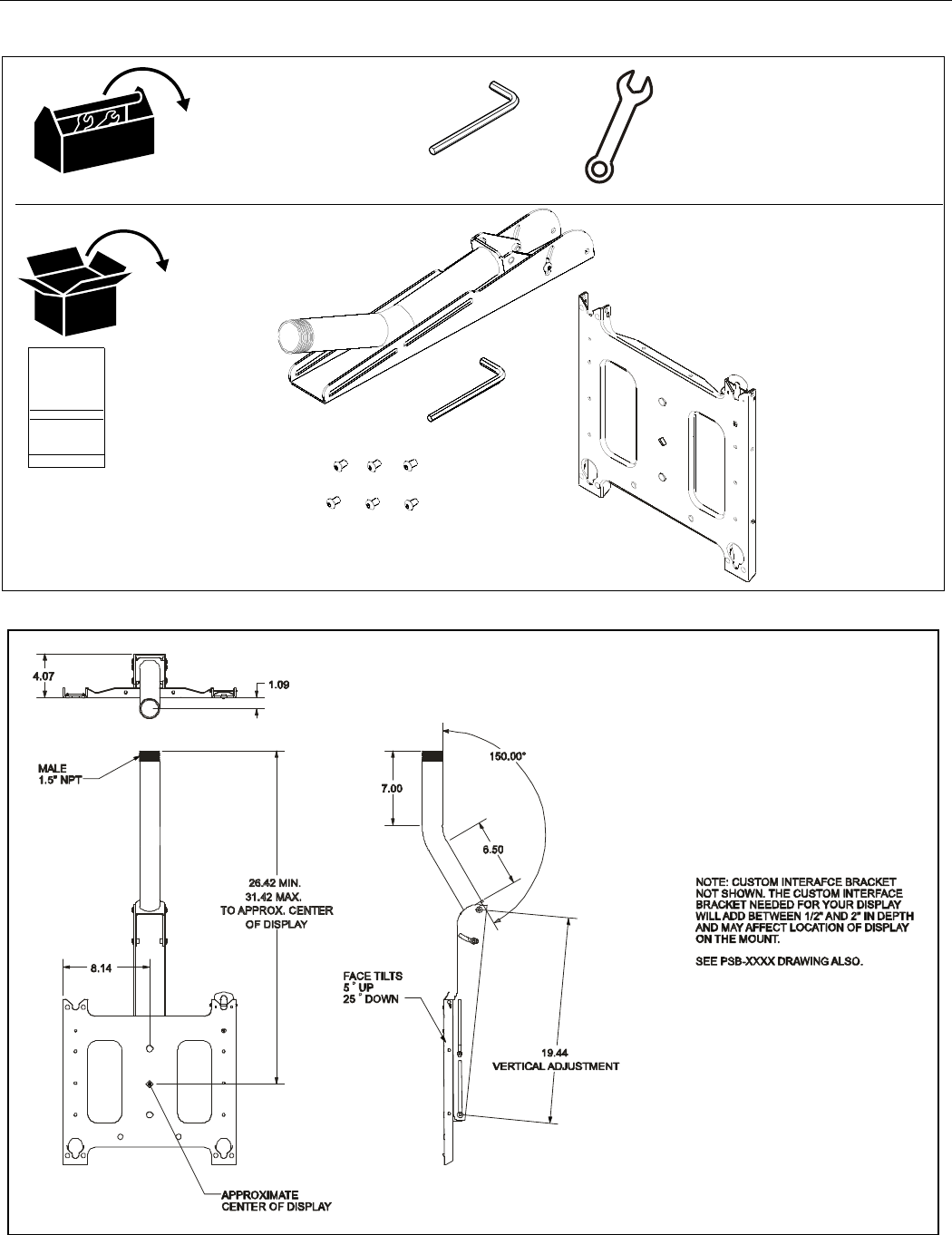
TOOLS REQUIRED FOR INSTALLATION AND PARTS
DIMENSIONS
Figure 1
x1
I/M
B (1)
3/16" (provided)
C (1)
D (6)
A (1)
PCM SERIES Installation Instructions
4
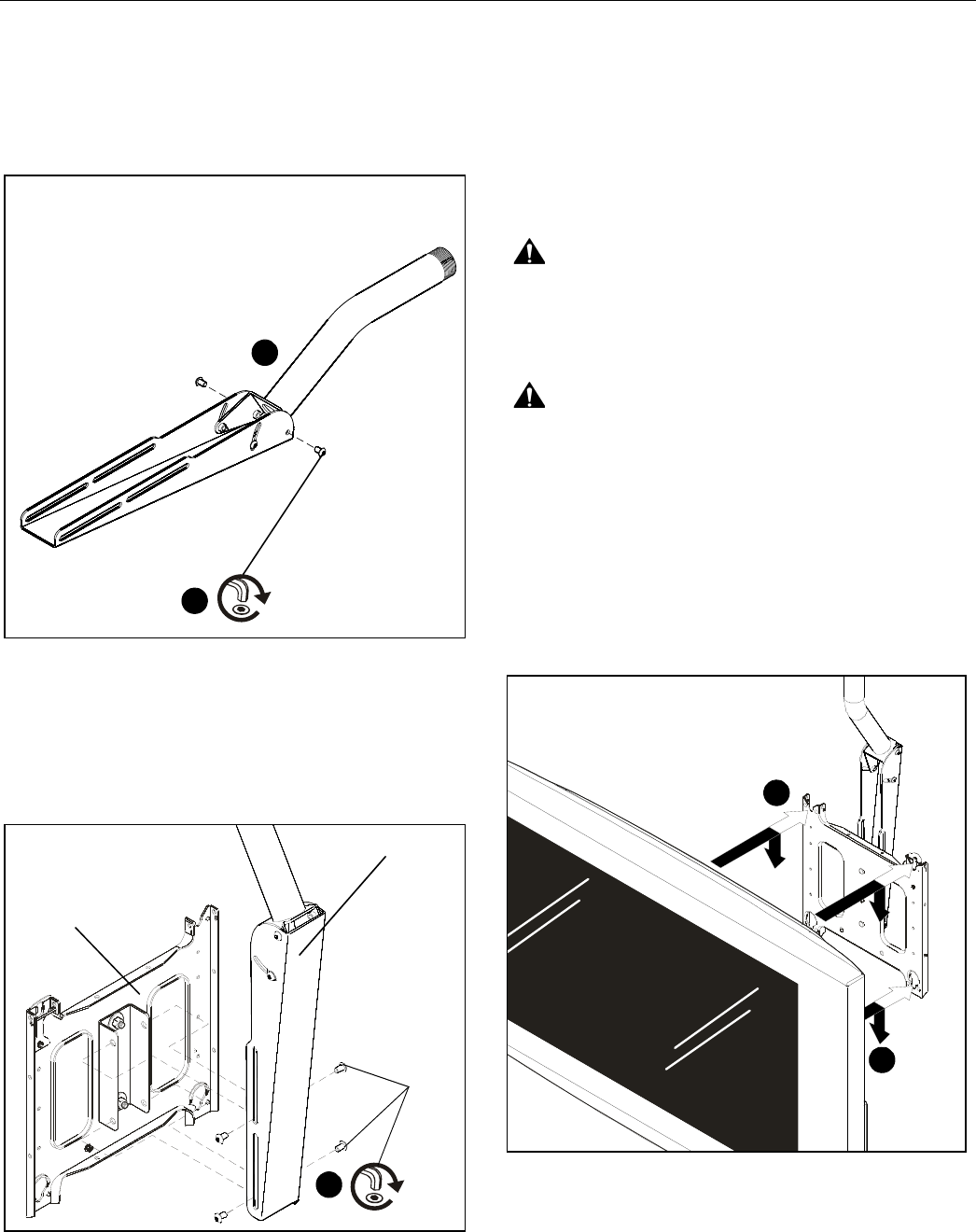
Mount Assembly and Installation
1. Fold tube out until tube mounting bracket rests against
faceplate mounting bracket. (See Figure 2)
2. Secure tube to faceplate mounting bracket using 3/16" hex
wrench (C) and two 5/16-18 x 1/2" button head cap screws
(D).
3. Tighten all hardware.
Figure 2
4. Thread the tube assembly (A) onto 1-1/2” NPT.
NOTE:
The product is suitable for use with a Listed ceiling
plate which can accommodate 1-1/2" NPT pipe, and
has a rated weight capacity of 200 lbs (91 kg).
5. Secure faceplate (B) to faceplate mounting bracket using
3/16" hex wrench (C) and four 5/16-18 x 1/2" button head
cap screws (D).
Figure 3
Display Installation
If the mounting pattern of the display being installed is a VESA
standard 200 x 200 pattern the mounting buttons can be
installed directly to the back of the display. If the display has any
other mounting pattern an interface bracket must be obtained
before proceeding. Consult a Chief Customer Service
representative if an interface bracket is required by calling
1-800-582-6480 or visit www.chiefmfg.com.
WARNING:
IMPROPER INSTALLATION CAN LEAD TO
MOUNT FALLING CAUSING SEVERE PERSONAL INJURY
OR DAMAGE TO EQUIPMENT. Displays can weigh in
excess of 40 lbs (18.1kg). ALWAYS use two people and
proper lifting techniques when installing display.
WARNING:
IMPROPER INSTALLATION CAN LEAD TO
MOUNT FALLING CAUSING SEVERE PERSONAL INJURY
OR DAMAGE TO EQUIPMENT. Make sure mounting buttons
on display are properly seated in mounting holes in faceplate.
To install display:
1. While supporting both sides of display, align four mounting
buttons on display or interface bracket with four mounting
holes in faceplate. (See Figure 4)
2. Lower display into place listening for audible "click" to
ensure recessed area of mounting buttons are properly
seated in lower area of mounting holes and "click lock"
mechanism has engaged. (See Figure 4) and
(See Figure 5)
Figure 4
NOTE:
Holes are provided in the faceplate for use with a
padlock or similar locking device, if desired. In addition,
the pin and nut may be removed from the upper holes
and moved to the lower holes for use as a more
permanent locking device. (See Figure 5)
1
(D) x 2
2
5
(A) x1
(D) x4
(B) x 1
2
1
Installation Instructions PCM SERIES
5
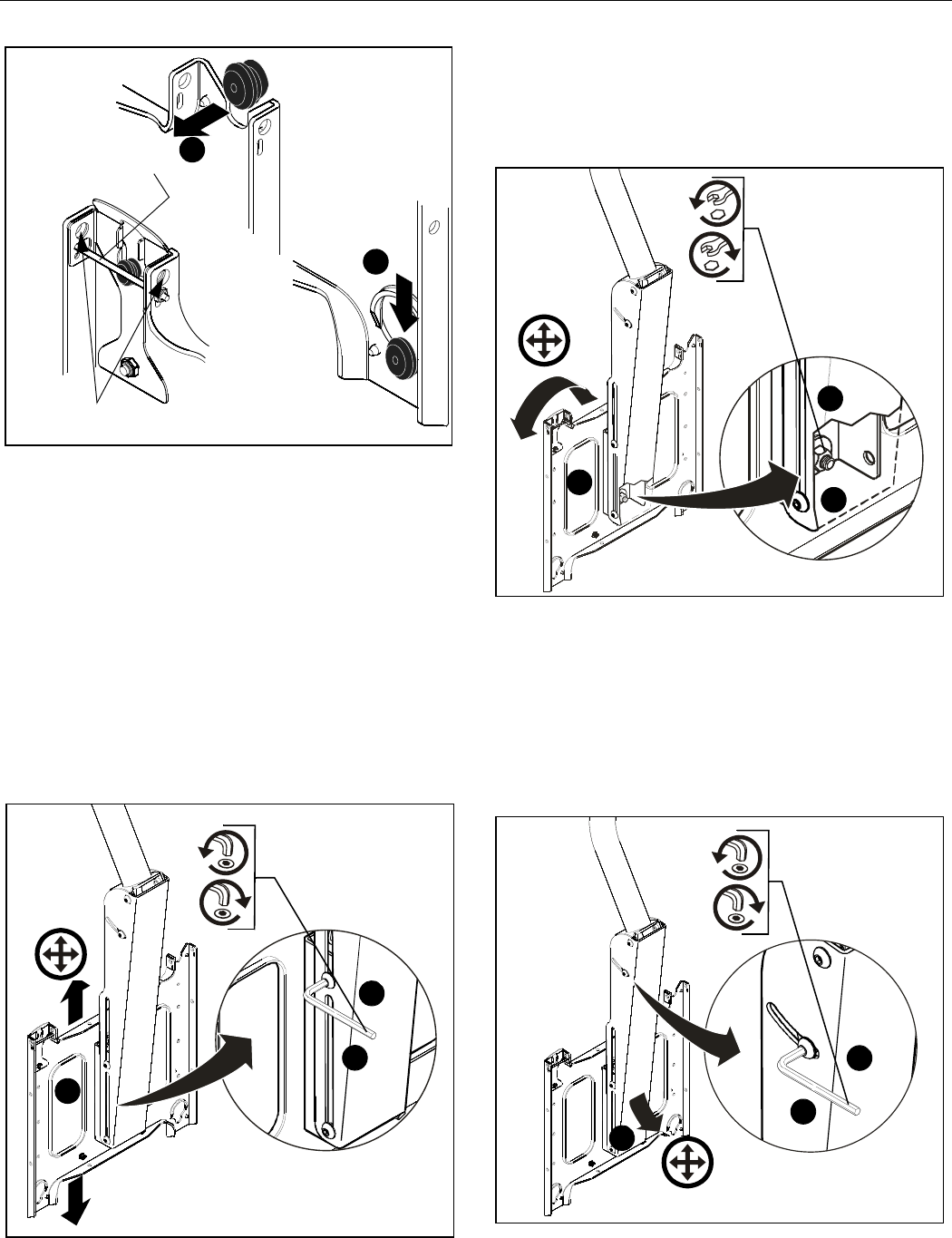
Figure 5
Adjustments
The PCM is designed to accommodate 5" of display height
adjustment, 4º right and left display roll adjustment, and 15º
down/5º up display pitch (Tilt) adjustment.
Remove display before performing adjustments.
Display Height Adjustment
To adjust display height:
1. Loosen four 5/16-18 button head cap screws using 3/16"
hex wrench (C). (See Figure 6)
2. Adjust faceplate to desired position. (See Figure 6)
3. Tighten four 5/16-18 button head cap screws using 3/16"
hex wrench (C). (See Figure 6)
Figure 6
Display Roll Adjustment
To adjust display roll:
1. Loosen 3/8-16 Nylock nut. (See Figure 7)
2. Adjust faceplate to desired position. (See Figure 7)
3. Tighten 3/8-16 Nylock nut. (See Figure 7)
Figure 7
Display Pitch (Tilt) Adjustment
To adjust display pitch:
1. Loosen four 5/16-18 button head cap screws.
(See Figure 8)
2. Adjust to desired tilt position. (See Figure 8)
3. Tighten four 5/16-18 button head cap screws.
(See Figure 8)
Figure 8
2
1
A padlock or bolt may
be placed through latch holes
To use as a
more permanent
lock, remove pin
and nuts and move
to lower holes
3
1
2
3
1
2
3
1
2

PCM SERIES Installation Instructions
6

Installation Instructions PCM SERIES
7

PCM SERIES Installation Instructions
Chief Manufacturing, a division of
Milestone AV Technologies
8805-000114 RevE
©2008 Milestone AV Technologies
www.chiefmfg.com
04/08
USA/International A 8401 Eagle Creek Parkway, Savage, MN 55378
P800.582.6480 / 952.894.6280
F877.894.6918 / 952.894.6918
Europe A Fellenoord 130 5611 ZB EINDHOVEN, The Netherlands
P+31 (0)40 2668620
F+31 (0)40 2668615
Asia Pacific A Room 24F, Block D, Lily YinDu International Building
LuoGang, BuJi Town, Shenzhen, CHINA.
P+86-755-8996 9226
F+86-755-8996 9217
Chief® and ClickConnect™ are trademarks of Milestone AV Technologies, Inc. All rights reserved.
