China Electric Manufacture RT01A Fan Remoter User Manual
Hong Kong China Electric Manufacture Co., Ltd Fan Remoter
UserManual.wiki
>
China Electric Manufacture
>
RT01A User Manual
user manual
Navigation menu
Upload a User Manual
Namespaces
Wiki Guide
HTML
PDF
Info
Views
User Manual
Discussion / Help
Navigation
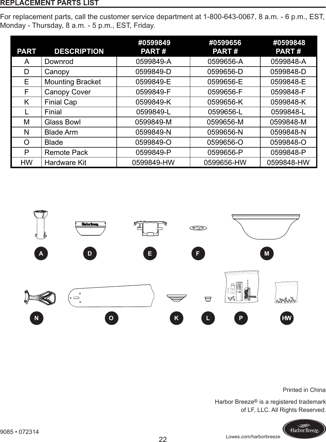
![3Lowes.com/harborbreezePACKAGE CONTENTSPART DESCRIPTION QUANTITYA Downrod 1B Downrod Pin (preassembled to Downrod [A]) 1C Downrod Clip (preassembled to Downrod [A]) 1D Canopy 1E Mounting Bracket (preassembled to the Canopy [D]) 1F Canopy Cover (preassembled to Canopy [D]) 1GMotor Assembly 1H Switch Housing (preassembled to Motor Assembly [G]) 1I Switch Housing Cap (preassembled to Light Kit [J]) 1J Light Kit 1K Finial Cap (preassembled to Light Kit [J]) 1L Finial (preassembled to Light Kit [J]) 1M Glass Bowl 1NBlade Arm 5O Blade 5P Remote Pack 1Q Bulb 3R Blade Balancing Kit 1S Rubber Washer (preassembled to Light Kit [J]) 1T Hex Nut (preassembled to Light Kit [J]) 1U Motor Screw (preassembled to Motor Assembly [G]) 10 + 1 extraV Switch Housing Screw (preassembled to Switch Housing Cap [I]) 3W Mounting Bracket Screw (preassembled to Mounting Bracket [E]) 4X Set Screw (preassembled to Motor Assembly [G]) 2Y Phillips-head Closemount Screw (preassembled to Motor Assembly [G]) 3ABCDIHGFJKLMN OEPQRS T U V W X Y](https://usermanual.wiki/China-Electric-Manufacture/RT01A/User-Guide-2800769-Page-3.png)