China Electric Manufacture RT01A Fan Remoter User Manual
Hong Kong China Electric Manufacture Co., Ltd Fan Remoter
user manual
1
ATTACH YOUR RECEIPT HERE
Serial Number _________________________ Purchase Date _________________________
Lowes.com/harborbreeze
Questions, problems, missing parts? Before returning to your retailer, call our customer
service department at 1-800-643-0067, 8 a.m. - 6 p.m., EST, Monday - Thursday, 8 a.m. - 5 p.m.,
EST, Friday.
Harbor Breeze® is a registered trademark
of LF, LLC. All Rights Reserved.
EB14216
ITEM #0599849, 0599656, 0599848
CROSSWINDS II CEILING FAN
MODEL #40821, 40823, 40822
Español p. 23

T
ABLE
OF
CONTENTS
Package Contents . . . . . . . . . . . . . . . . . . . . . . . . . . . . . . . . . . . . . . . . . . . . . . . . . . . . . . . . . . . . . . . . . 3
Hardware Contents . . . . . . . . . . . . . . . . . . . . . . . . . . . . . . . . . . . . . . . . . . . . . . . . . . . . . . . . . . . . . . . . 4
Safety Information . . . . . . . . . . . . . . . . . . . . . . . . . . . . . . . . . . . . . . . . . . . . . . . . . . . . . . . . . . . . . . . . . 5
Preparation . . . . . . . . . . . . . . . . . . . . . . . . . . . . . . . . . . . . . . . . . . . . . . . . . . . . . . . . . . . . . . . . . . . . . . 6
Initial Installation . . . . . . . . . . . . . . . . . . . . . . . . . . . . . . . . . . . . . . . . . . . . . . . . . . . . . . . . . . . . . . . . . . 7
Standard or Angle Mounting Instructions. . . . . . . . . . . . . . . . . . . . . . . . . . . . . . . . . . . . . . . . . . . . . . . . 9
Closemount Instructions . . . . . . . . . . . . . . . . . . . . . . . . . . . . . . . . . . . . . . . . . . . . . . . . . . . . . . . . . . . 11
Wiring . . . . . . . . . . . . . . . . . . . . . . . . . . . . . . . . . . . . . . . . . . . . . . . . . . . . . . . . . . . . . . . . . . . . . . . . . 12
Final Installation. . . . . . . . . . . . . . . . . . . . . . . . . . . . . . . . . . . . . . . . . . . . . . . . . . . . . . . . . . . . . . . . . . 13
Operating Instructions . . . . . . . . . . . . . . . . . . . . . . . . . . . . . . . . . . . . . . . . . . . . . . . . . . . . . . . . . . . . . 18
Care and Maintenance . . . . . . . . . . . . . . . . . . . . . . . . . . . . . . . . . . . . . . . . . . . . . . . . . . . . . . . . . . . . 19
T
roubleshooting . . . . . . . . . . . . . . . . . . . . . . . . . . . . . . . . . . . . . . . . . . . . . . . . . . . . . . . . . . . . . . . . . . 19
Limited Lifetime Warranty . . . . . . . . . . . . . . . . . . . . . . . . . . . . . . . . . . . . . . . . . . . . . . . . . . . . . . . . . . 21
Replacement Parts List . . . . . . . . . . . . . . . . . . . . . . . . . . . . . . . . . . . . . . . . . . . . . . . . . . . . . . . . . . . . 22
Warning . . . . . . . . . . . . . . . . . . . . . . .. . . . . . . . . . . . . . . . . . . . . . . . . . . . . . . . . . . . . . . . . . . . . . . . . . 23
2 Lowes.com/harborbreeze
3Lowes.com/harborbreeze
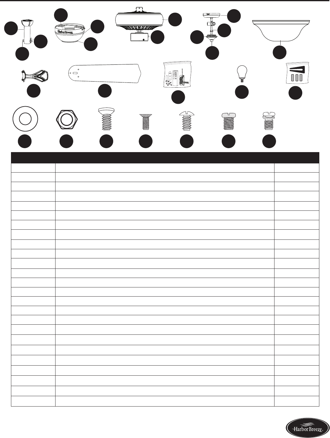
PACKAGE CONTENTS
PART DESCRIPTION QUANTITY
A Downrod 1
B Downrod Pin (preassembled to Downrod [A]) 1
C Downrod Clip (preassembled to Downrod [A]) 1
D Canopy 1
E Mounting Bracket (preassembled to the Canopy [D]) 1
F Canopy Cover (preassembled to Canopy [D]) 1
GMotor Assembly 1
H Switch Housing (preassembled to Motor Assembly [G]) 1
I Switch Housing Cap (preassembled to Light Kit [J]) 1
J Light Kit 1
K Finial Cap (preassembled to Light Kit [J]) 1
L Finial (preassembled to Light Kit [J]) 1
M Glass Bowl 1
NBlade Arm 5
O Blade 5
P Remote Pack 1
Q Bulb 3
R Blade Balancing Kit 1
S Rubber Washer (preassembled to Light Kit [J]) 1
T Hex Nut (preassembled to Light Kit [J]) 1
U Motor Screw (preassembled to Motor Assembly [G]) 10 + 1 extra
V Switch Housing Screw (preassembled to Switch Housing Cap [I]) 3
W Mounting Bracket Screw (preassembled to Mounting Bracket [E]) 4
X Set Screw (preassembled to Motor Assembly [G]) 2
Y Phillips-head Closemount Screw (preassembled to Motor Assembly [G]) 3
A
B
C
D
I
H
G
F
J
K
LM
N O
E
PQR
S T U V W X Y
4Lowes.com/harborbreeze
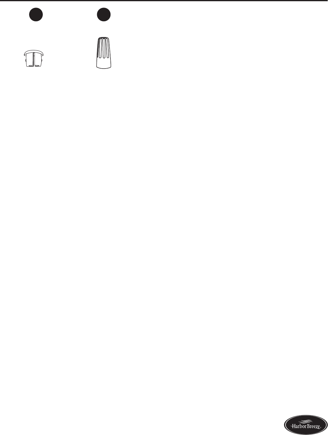
HARDWARE CONTENTS (shown actual size)
Plug Button
Qty. 1
Wire Connector
Qty. 1
+1 extra
AA BB
5Lowes.com/harborbreeze
SAFETY INFORMATION
Please read and understand this entire manual before attempting to assemble, operate or install the
product.
• Before you begin installing the fan, disconnect the power by removing fuses or turning off the circuit
breakers.
• Make sure all electrical connections comply with local codes, ordinances, the National Electrical
Code,andANSI/NFPA70-199.Hireaqualiedelectricianorconsultado-it-yourselfwiring
handbook if you are unfamiliar with installing electrical wiring.
• Make sure the installation site you choose allows a minimum clearance of 7 ft. from the blades to
theoorandatleast30in.fromtheendofthebladestoanyobstruction.
• The net weight of this fan is: 16.4 lbs.
DANGER: When using an existing outlet box, make sure the outlet box is securely attached to
the building structure and can support the full weight of the fan. Failure to do this can result in serious
injury or death. The stability of the outlet box is essential in minimizing wobble and noise in the fan
after installation is complete.
WARNING: To avoid personal injury, the use of gloves may be necessary while handling fan
parts with sharp edges.
WARNING: Using a full-range dimmer switch to control fan speed will cause a loud humming
noisefromthefan.Toreducetheriskofreorelectricshock,doNOTuseafull-rangedimmerswitch
to control the fan speed.
WARNING: Toreducetheriskofre,electricshock,orpersonalinjury,mountthefantoan
outlet box marked “ACCEPTABLE FOR FAN SUPPORT” and use the mounting screws provided with
theoutletbox.Mostoutletboxescommonlyusedforthesupportoflightingxturesarenotacceptable
forfansupportandmayneedtobereplaced.Consultaqualiedelectricianifindoubt.Securethe
outlet box directly to the building structure. The outlet box and its support must be able to support the
moving weight of the fan (at least 35 lbs.).
WARNING: Toreducetheriskofre,electricshock,orpersonalinjury,wireconnectors
provided with this fan are designed to accept only one 12-gauge house wire and two lead wires from
the fan. If your house wire is larger than 12 gauges and/or there is more than one house wire to
connect to the two fan lead wires, consult an electrician for the proper size wire connectors to use.
WARNING: Toreducetheriskofre,electricshockorpersonalinjury,donotbendtheblade
arms when installing them, balancing the blades, or cleaning the fan. Do not insert objects between
the rotating fan blades.
WARNING: To reduce the risk of personal injury, use only parts provided with this fan. The use
of parts OTHER than those provided with this fan will void the warranty.
6Lowes.com/harborbreeze
SAFETY INFORMATION
CAUTION: Read all instructions and safety information before installing your new fan. Review the
accompanying assembly diagrams.
CAUTION: Be sure the outlet box is properly grounded or that a ground (green or bare) wire is present.
CAUTION: Carefully check all screws, bolts and nuts on the fan motor assembly to ensure they are
secured.
CAUTION: This device complies with Part 15 of the FCC Rules. Operation is subject to the following
two conditions: (1) this device may not cause harmful interference, and (2) this device must accept
any interference received, including interference that may cause undesired operation.
PREPARATION
Before beginning the assembly of this product, ensure all parts are present. Compare all parts with
the package contents list and hardware contents list. If any part is missing or damaged, do not
attempt to assemble the product.
Estimated Assembly Time: 120 minutes
Tools Required for Assembly (not included): Electrical Tape, Phillips Screwdriver, Pliers, Safety
Glasses, Step Ladder, Wire Cutters and Wire Strippers
Helpful Tools (not included): AC Tester Light, Tape Measure and Wiring Handbook
7Lowes.com/harborbreeze
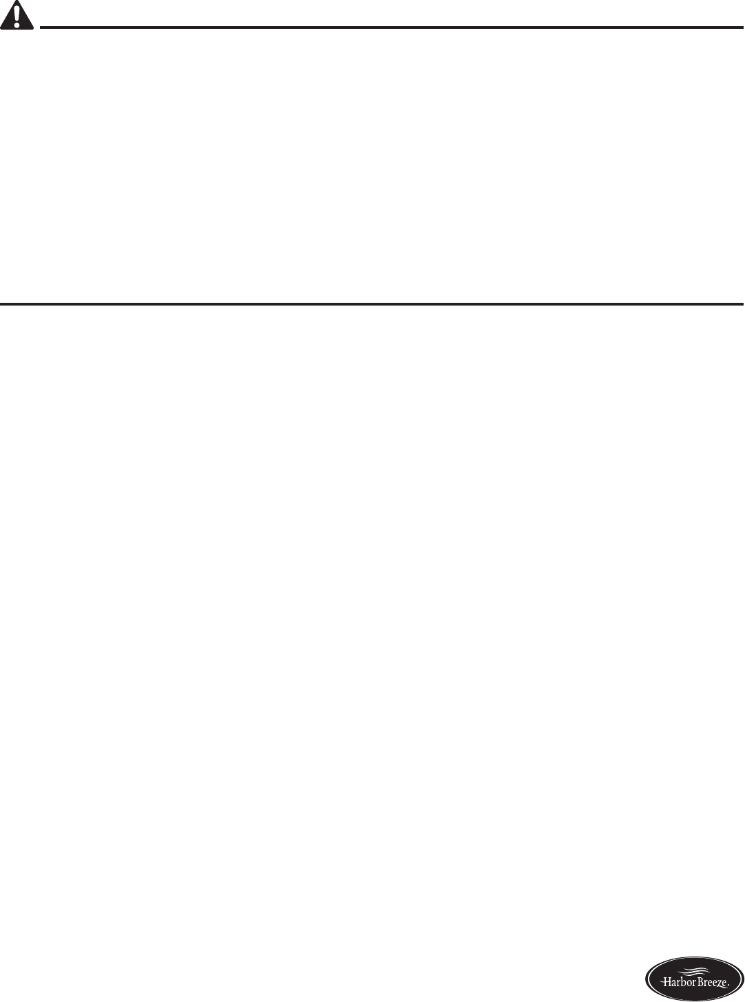
INITIAL INSTALLATION
1. Turn off the circuit breakers and the wall switch to the
fan supply line leads.
DANGER: Failure to disconnect the power
supply prior to installation may result in serious injury
or death.
2. Determine the mounting method to use.
Helpful Hint: Standard mounting is best suited for
ceilings 8 ft. or higher. For taller ceilings you may
want to use a longer downrod (sold separately). Angle
mounting is best suited for angled or vaulted ceilings.
A longer downrod is sometimes necessary to ensure
proper blade clearance. Closemount-style mounting
is more suitable for ceilings lower than 8 ft. high.
Flushmount installation is not available for this item.
Important: If using the angle mount, check to ensure
the ceiling angle is not steeper than 10°.
2
Standard Mounting
Flushmount Closemount
Angle Mounting
3. Ensure the blades (O) will be at least 30 in. from
any obstructions. Also check the downrod (A) length
to ensure the blades (O) will be at least 7 ft. above
theoor.
7 ft. min.
30 in. min.
3
A
O
1
8Lowes.com/harborbreeze
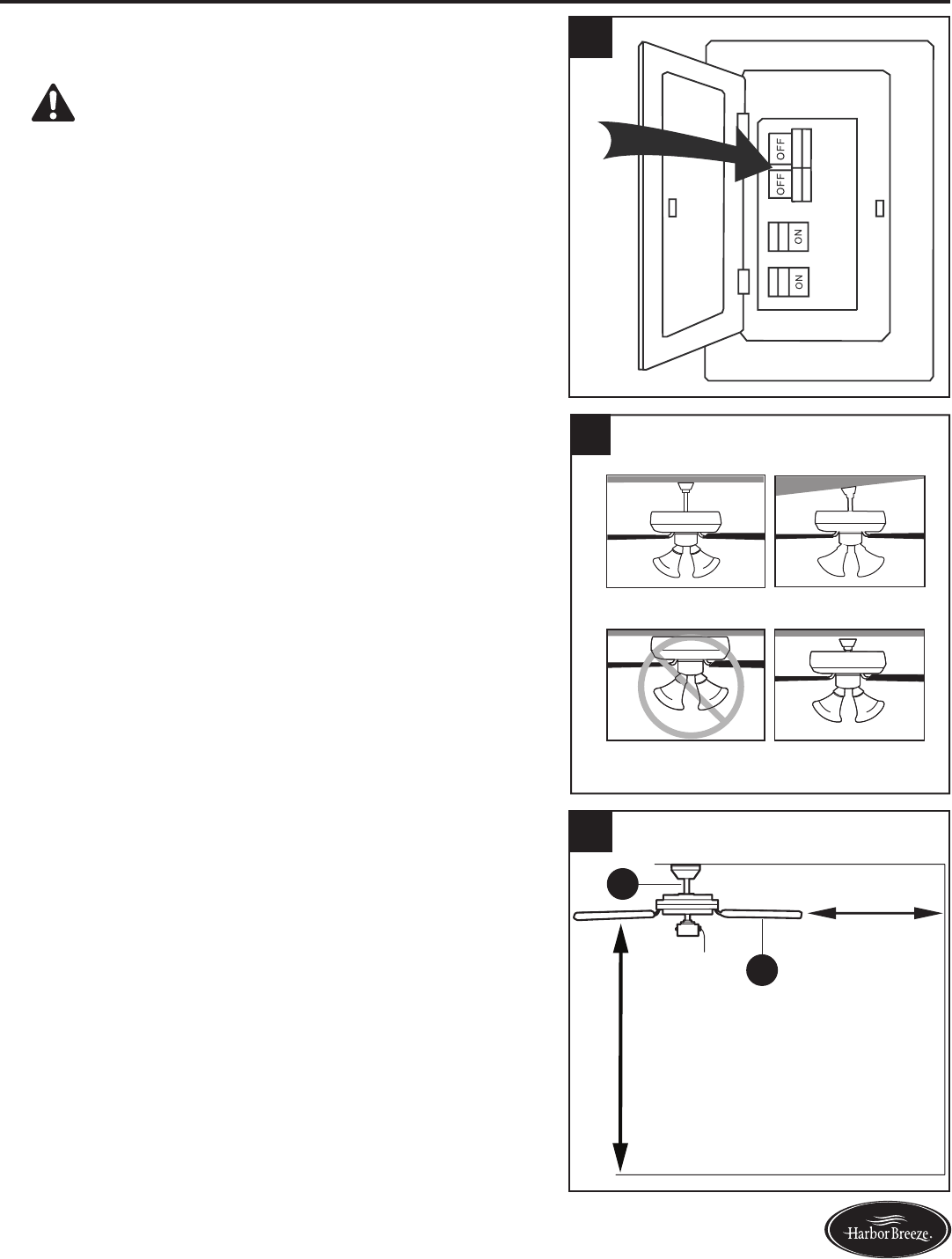
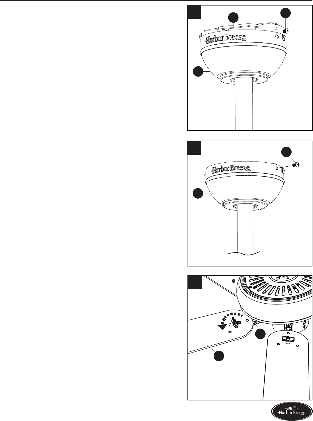
INITIAL INSTALLATION
4. Loosen all four mounting brackets screws (W),
then completely remove the two mounting bracket
screws (W) from the round holes of canopy (D). Set
aside for later use.
Detach mounting bracket (E) from canopy (D).
Note: Do NOT remove the mounting bracket screws
(W) from the slotted holes.
5. Extend the supply wires from outlet box (not
included) to one side of the mounting bracket (E)
and secure the mounting bracket (E) to the outlet
box using screws and washers provided with the
outlet box.
CAUTION: It is very important you use the proper
hardware when installing the mounting bracket (E) as
this will support the fan.
Note: Do not feed supply wires through the hole in the
top of the mounting bracket.
Important: If using the angle mount, ensure the open
end of the mounting bracket (E) is installed facing the
higher point of the ceiling.
6. Remove all ten preassembled motor screws (U) and
vepreassembedmotorblocksfromtheundersideof
the motor assembly (G). Then install the blade arms
(N) into the underside of the motor assembly (G)
using the ten motor screws (U).
Discard the motor blocks.
For Standard or Angle Mounting Instructions, continue
to page 9. For Closemount Instructions, proceed to
page 11.
D
W
E
E
E
4
5Standard or
Closemount
Mounting
Angled
Mounting
6
Motor
Block
U
G
N
G
U
9Lowes.com/harborbreeze
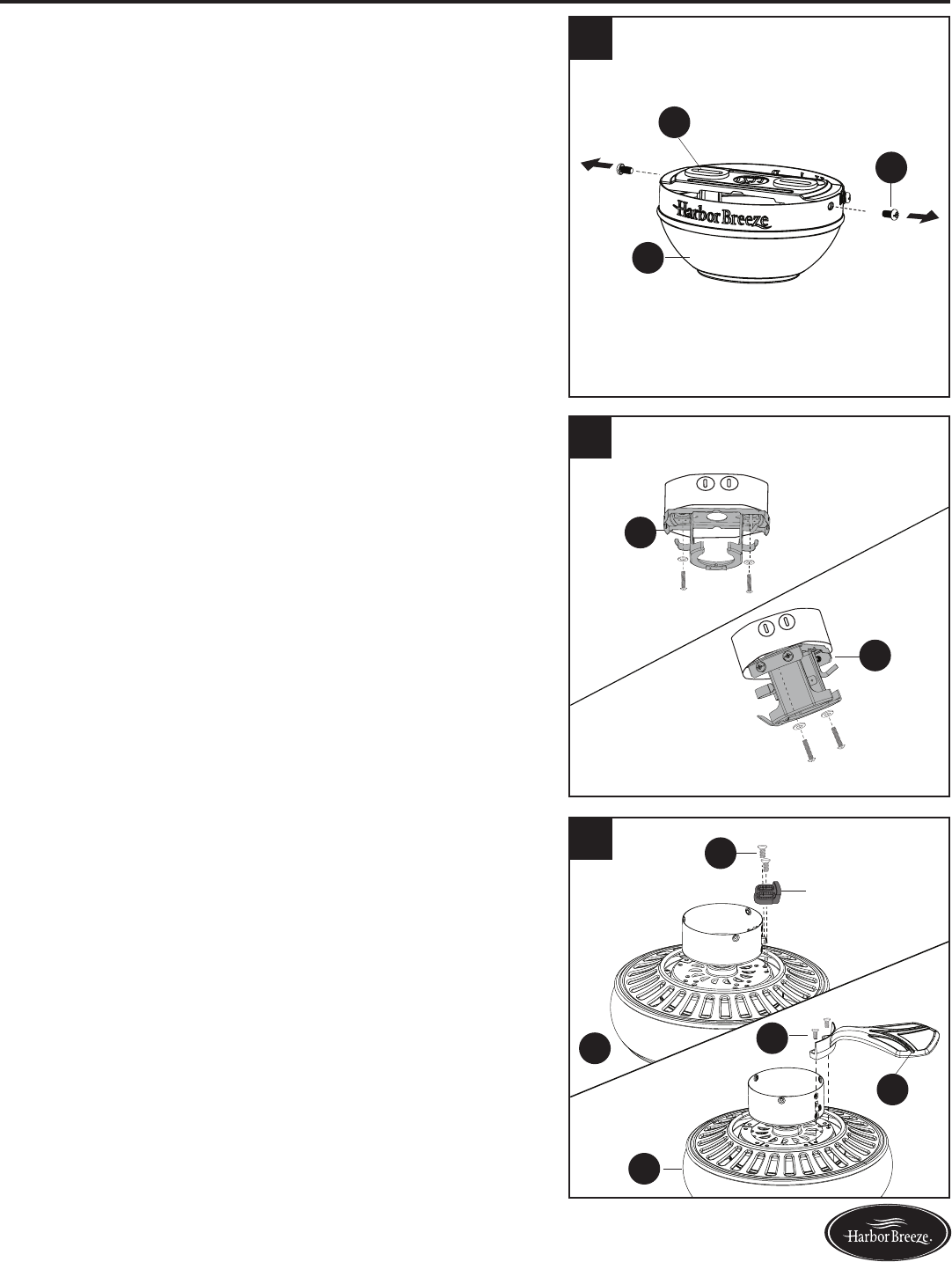
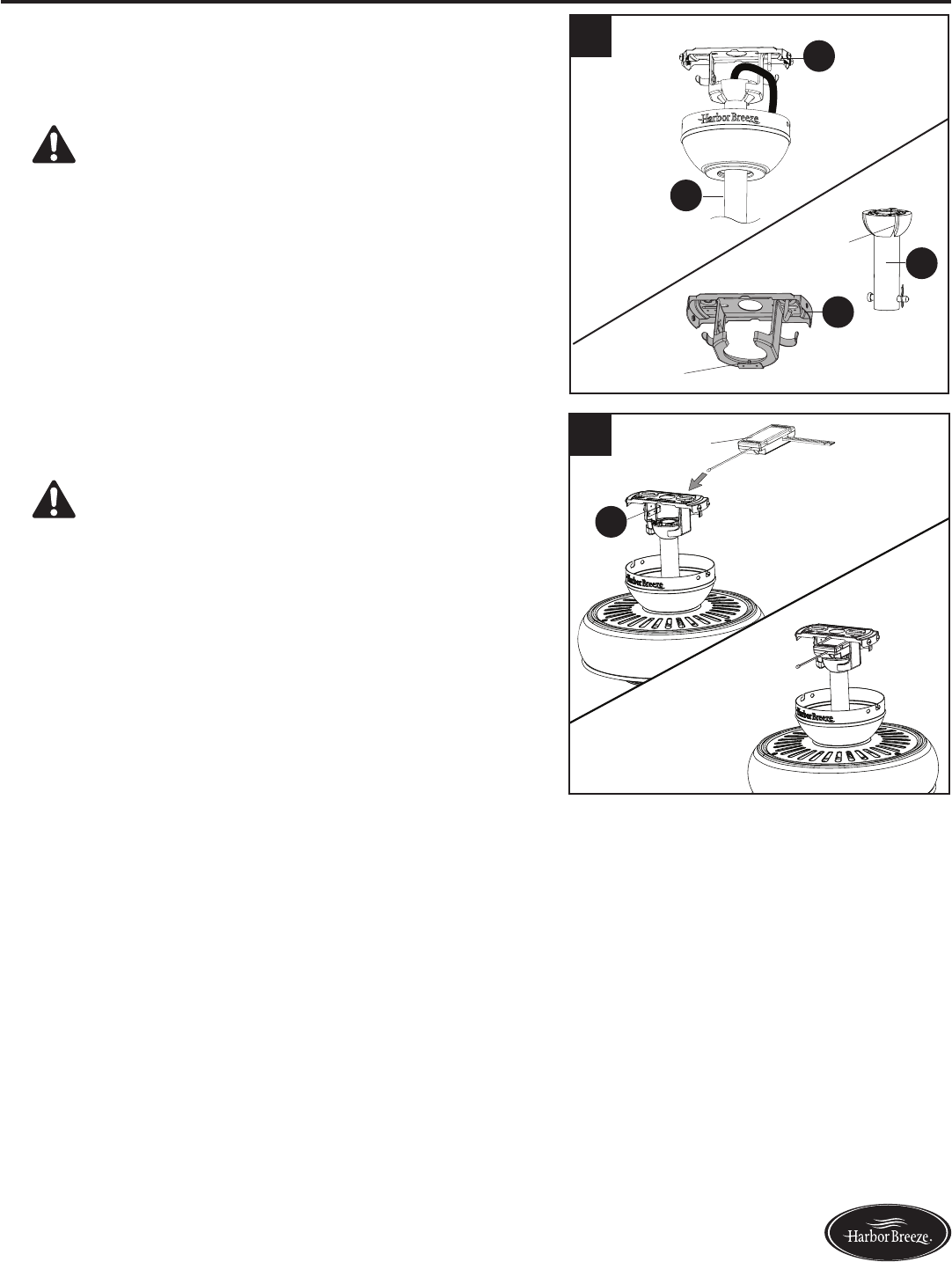
STANDARD OR ANGLE MOUNTING INSTRUCTIONS
1. Partially loosen the two set screws (X) in the yoke
at the top of the motor assembly (G) to allow for
installation of the downrod (A).
2. Remove the downrod pin (B) and downrod clip (C)
from the downrod (A). Insert downrod (A) -- or a
longer downrod, if purchased -- through canopy (D),
then feed the wire harness from the fan through the
downrod (A). Secure downrod (A) into the yoke of
motor assembly (G).
3. Align the holes of downrod (A) and the yoke of motor
assembly (G), then re-install the downrod pin (B) and
downrod clip (C). Once secure, re-tighten the set
screws (X).
C
B
G
A
A
G
B
A
G
C
X
D
2
3
1
X
Yoke
10 Lowes.com/harborbreeze
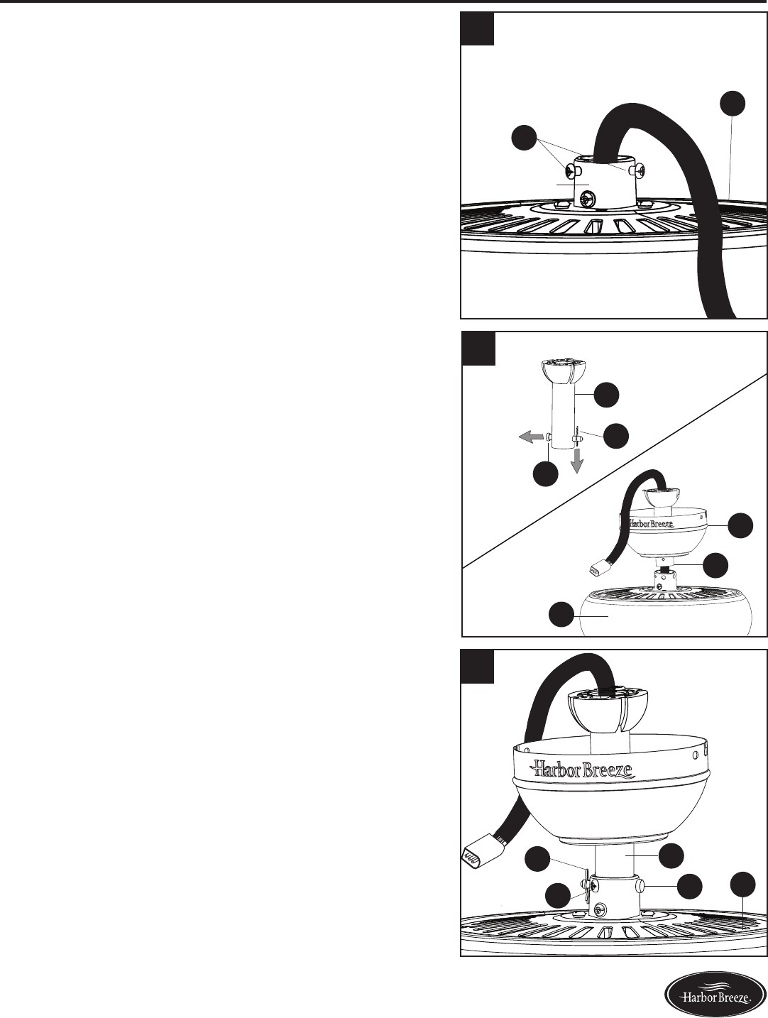
STANDARD OR ANGLE MOUNTING INSTRUCTIONS
4. Install the ball end of the downrod (A) into the opening of
the mounting bracket (E). Rotate the fan in the mounting
bracket (E) until a slot in the ball end of the downrod (A)
engages the tab in the mounting bracket (E).
DANGER: The fan and/or downrod (A) should
not rotate in the mounting bracket (E) if installed
correctly. Failure to align the slot with the tab may
result in fan falling causing serious injury or death.
5. Insert the receiver from remote pack (P) into the
mountingbracket(E)withtheatsideofthereceiver
facing the ceiling.
WARNING: Using a full-range dimmer switch to
control fan will cause a loud humming noise from the
fananddamagetheremote.Toreducetheriskofre
or electric shock, do NOT use a full-range dimmer
switch to control the fan speed.
Proceed to WIRING on page 12.
4
A
A
E
E
Tab
Slot
E
5Receiver
11 Lowes.com/harborbreeze
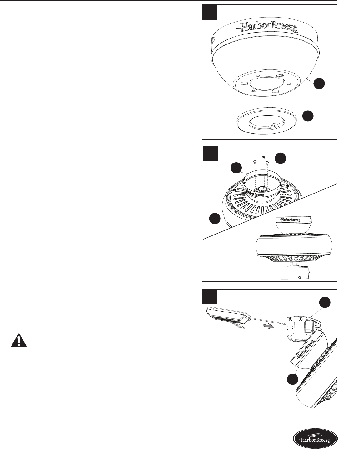
CLOSEMOUNT INSTRUCTIONS
1. Remove and discard the canopy cover (F) from the
bottom of the canopy (D).
Note: The downrod (A) and canopy cover (F) are not
used in this type of installation.
2. Remove the three Phillips-head closemount screws
(Y) from the top of the motor assembly (G). Align
the canopy (D) with the holes in the top of motor
assembly (G), then re-install the Phillips-head
closemount screws (Y) to secure the canopy (D) to
the top of the motor assembly (G).
3. Raise the fan and place the canopy (D) on the hook
on the mounting bracket (E) temporarily leaving hands
free for the wiring process. Then, place the receiver
from remote pack (P) inside the mounting bracket (E)
withatsidefacingtheceiling.
WARNING: Using a full-range dimmer switch to
control fan will cause a loud humming noise from the
fananddamagetheremote.Toreducetheriskofre
or electric shock, do NOT use a full-range dimmer
switch to control the fan speed.
D
F
3E
D
Receiver
Y
G
D
1
2
12 Lowes.com/harborbreeze
WIRING
WARNING:Toreducetheriskofre,electricalshockorpersonalinjury,wireconnectorsprovided
with this fan are designed to accept only one 12-gauge house wire and two lead wires from the fan. If
your house wire is larger than 12 gauges and/or there is more than one house wire to connect to the
fan lead wire (red), consult an electrician for the proper size wire connectors to use.
CAUTION: Be sure the outlet box is properly grounded or that a ground (green or bare) wire is present.
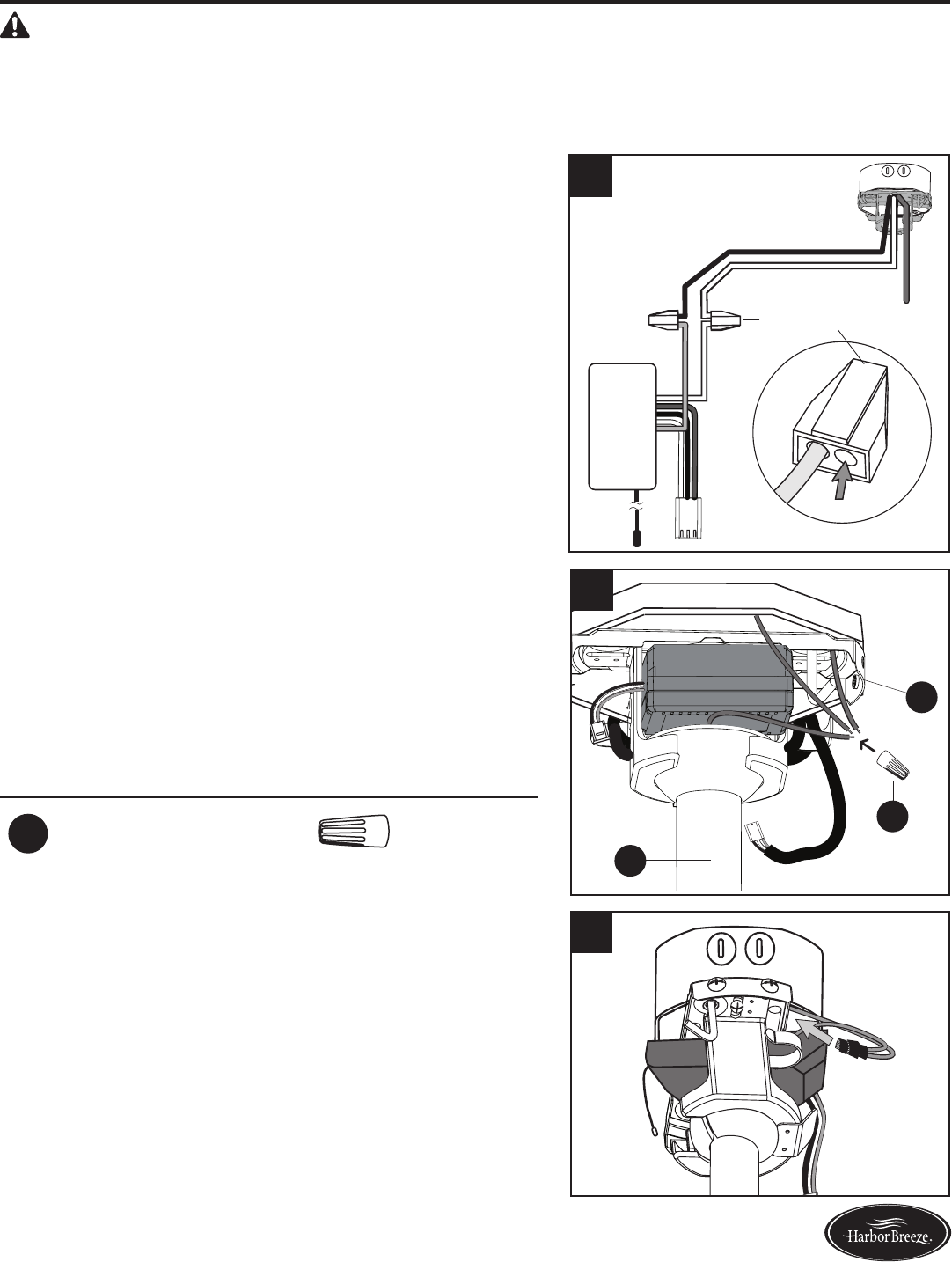
1. Make the following wire connections according to the
diagram and these steps:
•PushtheWhite(common/neutral)supplywireinto
the empty wire hole of the push-in wire connector
preassembled to the White wire from the receiver of
remote pack (P).
•PushtheBlack(Live/Hot)supplywireintotheempty
wire hole in push-in wire connector preassembled to
the Red wire from the receiver of remote pack (P).
Important: The wire harness and the Bare/Green
(ground) supply wire will be connected later. If supply
wires are different colors than referred to above, a
professional electrician should determine proper wiring.
CAUTION: Fan must be installed with included
receiver.
Black (Live/Hot)
Bare/Green
(Ground)
White (Common/Neutral)
Wire Harness
White
A
ntenna
Red
ReceiverReceiver
Push-in Wire
Connector
2. Connect the Green wires from the downrod (A) and
the mounting bracket (E) to the Bare/Green (ground)
supply wire using a wire connector (BB). Note:
Closemount installation does not use a downrod (A),
so there will only be two Green wires to connect.
Then, wrap electrical tape (not included) around the
wire connector (BB) down to the wire.
Hardware Used
BB Wire Connector x 1
3. Turn the spliced/taped wires upward and gently push
the wires and connectors into the outlet box.
WARNING: Ensure no bare wire strands are visible
after making connections. Place White wire connections
on opposite sides of outlet box from the Black.
1
E
2
A
BB
3
13 Lowes.com/harborbreeze
FINAL INSTALLATION
Note: Closemount installation will not have the downrod (A) or canopy cover (F). Downrod (A)
is shown/referenced, but instructions are applicable to both standard and closemount-style
installations.
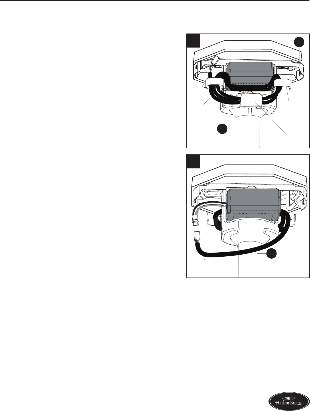
1. Read and discard the paper tag attached to the wire
hooks of the mounting bracket (E). Wrap the wire
harness coming from the downrod (A) around the
wire hooks.
Important: Ensure the wire harness is supported
by the wire support to prevent damage to the wire
harness during canopy installation.
Note: Extra wire harness length accommodates
longer downrods.
2. Connect the wire harness from the downrod (A) to the
wire harness from the receiver from remote pack (P).
1
2
A
E
AWire
Support
Wire
Harness
Wire Hook
Wire Harness
14 Lowes.com/harborbreeze
FINAL INSTALLATION
3. Align the canopy (D) over the loose mounting bracket
screws (W) preassembled on mounting bracket
(E). Place the keyholes of the canopy (D) onto the
mounting bracket screws (W) and rotate the canopy
(D) counterclockwise.
Note: While raising the canopy (D), avoid pinching
wiring or antenna of the receiver of remote pack (P)
between the mounting bracket (E) and the canopy (D).
4. Secure the canopy (D) with the mounting bracket
screws (W) previously removed (Step 4, page 8).
Tighten all mounting bracket screws (W) securely.
5. Align the holes in a blade (O) over the pins on a blade
arm (N). Push the pins through the blade and twist the
lock on the blade arm (N) counterclockwise to secure
the blade (O).
Repeat for remaining blades (O).
N
O
5
D
W
D
E
W
3
4
15 Lowes.com/harborbreeze
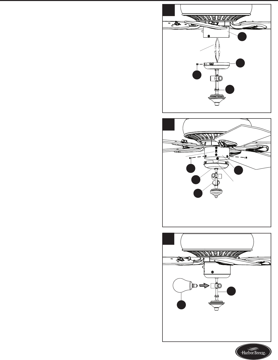
FINAL INSTALLATION
Note: If you wish to install the fan without the light kit,
proceed to step 11.
6. To install the light kit (J),rstremoveallthree
switch housing screws (V) from the switch housing
cap (I). Then connect the single-pin connectors from
the switch housing (H) to the single-pin connectors
from the light kit (J) -- blue to black and white to white.
7. Align the notch in the switch housing cap (I) with the
reverse switch on the switch housing (H). Then secure
the light kit (J) to the switch housing (H) using the
previously removed switch housing screws (V).
8. Install the bulbs (Q) into the sockets on the light kit (J).
IMPORTANT: Make sure you allow the bulbs (Q) and
light kit (J) to cool before you replace the bulbs.
6
H
J
I
V
H
J
I
V
7
8
Q
J
Notch
Reverse
Switch
Single-pin
Connector
16 Lowes.com/harborbreeze
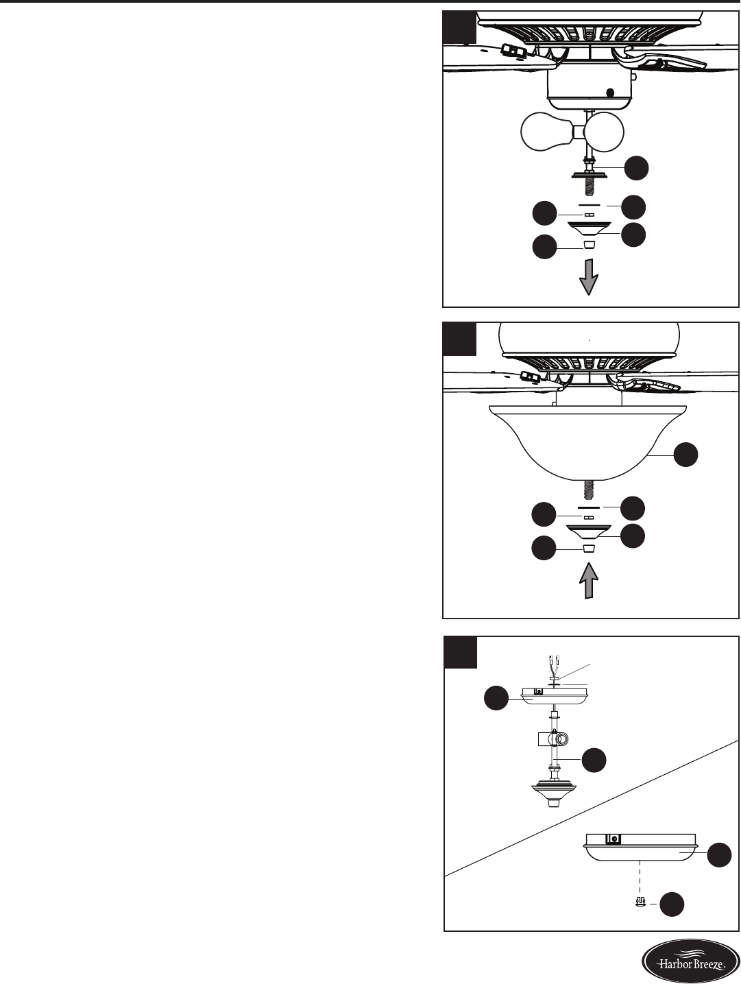
FINAL INSTALLATION
9.Removethepreassemblednial(L),nialcap(K),hex
nut (T) and rubber washer (S) from the light kit (J).
10. Lift the glass bowl (M) onto the threaded rod at the
bottom of the light kit (J). Re-install rubber washer (S)
andsecurewithhexnut(T).Liftthenialcap(K)onto
thethreadedrod,securingwithnial(L).
Proceed to step 13.
11. To install the fan without the light kit (J), remove
the hex nut and lock washer from the rod on the
inside of the switch housing cap (I). Remove light kit
(J) from the switch housing cap (I) and discard, then
install the plug button (AA) into the center hole of the
switch housing cap (I).
12
10
9
S
J
S
M
T
T
K
K
L
L
AA
I
J
I
11 Hex Nut
Washer
17 Lowes.com/harborbreeze
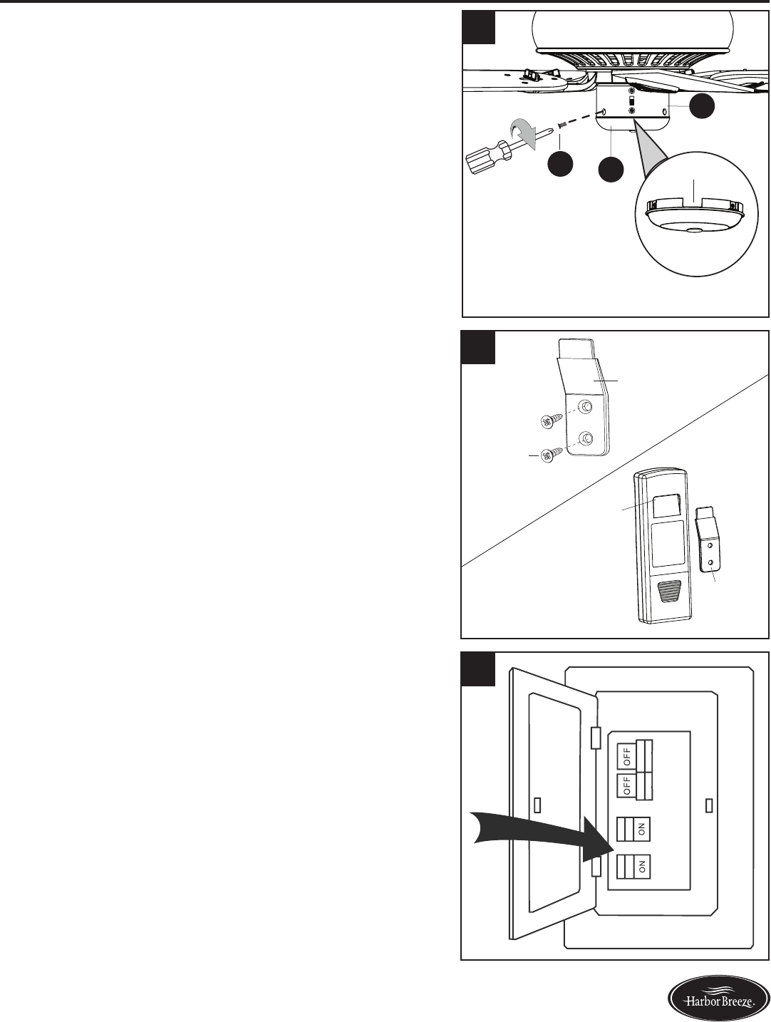
FINAL INSTALLATION
12. Remove all three switch housing screws (V) from the
switch housing cap (I). Align the notch in the switch
housing cap (I) with the reverse switch located on
switch housing (H), then re-install all three switch
housing screws (V).
13. OPTIONAL: If you wish to install the wall bracket
from remote pack (P), choose desired location and
insert screws from remote pack (P) into holes of wall
bracket and into installation site. Store the remote
from remote pack (P) on the wall bracket by placing
the slot on the back of the remote onto the wall
bracket.
14. Turn on the circuit breakers and the wall switch to the
fan supply line leads.
Assembly is complete.
12
H
14
13
VINotch
Wall Bracket
Wall
Bracket
Slot
Screw
18 Lowes.com/harborbreeze
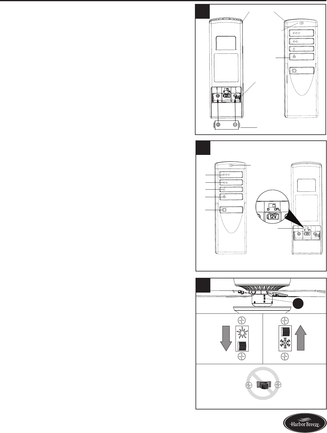
OPERATING INSTRUCTIONS
1. Remove the battery cover from the back of the remote
found in remote pack (P). Insert the battery from
remote pack (P) into the remote; ensure polarity of
battery matches the polarity indicated in the battery
compartment -- positive (+) to positive (+) and negative
(-) to negative (-). Replace the battery cover and press
the fan power button on the remote to ensure the LED
indicator illuminates and the remote turns on the fan.
Note: If remote doesn’t turn on the fan, see
TROUBLESHOOTING (page 20).
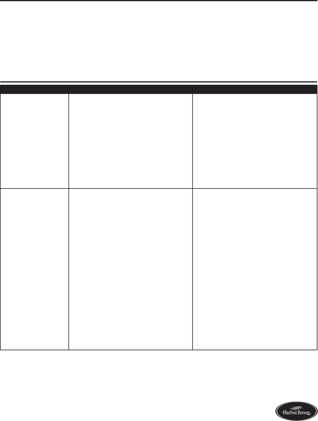
2. To operate the fan using the remote, press and release
the following buttons:
1 - High fan speed
2 - Medium fan speed
3 - Low fan speed
4 - Fan Power - Turns the fan off.
Light Delay Off mode - Press and hold the fan
powerbutton(4)forveseconds,whichwillturn
off light after one minute. The LED indicator on the
remotewillashfourtimestoconrmmodesetting.
5 - Light Control:
Incandescent Bulbs - Press light control to turn
lights off and on. Press and hold light control to
dim or brighten the lights.
CFL Bulbs -Turns the lights on and off. Note: The
dimmer function does not work with CFL bulbs.
6 - D/CFL Switch: Switch should be set to “D” to
correspond with the included incandescent bulbs,
which will enable the dimming function. Flip to
“CFL” if you change to corresponding bulbs.
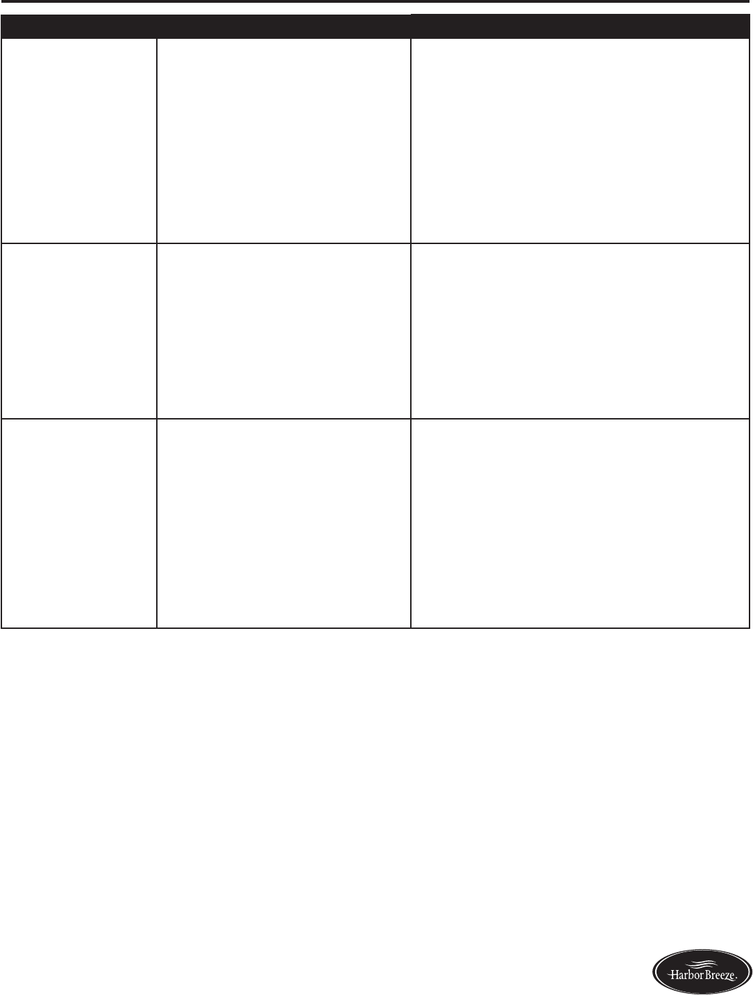
3. The reverse switch is located on the switch housing (H).
Using a ceiling fan will allow you to raise your
thermostat setting in summer and lower your
thermostat setting in winter without feeling a
difference in your comfort. Note: Wait for the fan to
stop before moving the reverse switch.
In warmer weather, push the reverse switch down to
displayasunicon,whichwillresultindownwardairow
creating a wind chill effect (Fig. 3a).
In cooler weather, push the reverse switch up to
displayasnowakeicon,whichwillresultinupward
airowthatcanhelpmovehotairofftheceilingarea
(Fig. 3b).
Important: The reverse switch must be set either
completely up or down in order for the fan to function
correctly. If the reverse switch is set in the middle
position, the fan will not operate (Fig. 3c).
1
2
3
4
5
6
2
1Remote
Front Back
Battery
Battery
Compartment
Fig. 3a Fig. 3b
Fig. 3c
3
H
2
LED Indicator
LED Indicator
Fan Power
19 Lowes.com/harborbreeze
CARE AND MAINTENANCE
At least twice each year, tighten all screws on the fan. Clean the motor housing with only a soft
brushorlint-freeclothtoavoidscratchingthenish.Cleanthebladeswithalint-freecloth.Youmay
occasionally apply a light coat of furniture polish to wood blades for added protection.
Bulb Replacement: Use 40-watt max. candelabra-base bulbs or CFL equivalent.
Battery Replacement for Remote: Use A23 12-volt battery.
Important: Shut off the main power supply before you begin any maintenance tasks. Do not use
water or a damp cloth to clean the ceiling fan.
TROUBLESHOOTING
PROBLEM POSSIBLE CAUSE CORRECTIVE ACTION
The fan does not
move.
1. The power is off or the fuse is
blown.
2. There is a faulty wire connection.
3. The plugs are not connected
properly.
4. The reverse switch is not
completely engaged.
1. Turn the power on or check the
fuse.
2. Turn the power off. Loosen the
canopy and check all connections.
3. Check that the connectors from
the light kit and fan are connected
properly.
4. Push the reverse switch
completely to the left or right.
There is excessive
wobbling.
1. The blades and/or blade are
loose.
2. The blades are unbalanced.
3. The fan mounting is not secure.
4. The fan is too close to vaulted
ceiling.
5. Set screw on the yoke of the
motor housing is loose.
1. Check and tighten all screws that
hold the fan blades to the blade
arms and the blade arms to the
motor.
2. Switch one blade with a blade
from the opposite side. Or balance
the fan using the blade balancing
kit (R).
3. Turn off the power. Verify the
mounting bracket is secure to the
electrical outlet box. The bracket
mustbeushwithoutmovement
against the outlet box.
4. Use a longer downrod (sold
separately) or move fan to a
different location.
5. Tighten the set screw on the yoke
of the motor housing.
20 Lowes.com/harborbreeze
TROUBLESHOOTING
PROBLEM POSSIBLE CAUSE CORRECTIVE ACTION
The fan is noisy.
1. The blades are loose.
2. There is a cracked blade.
3. The outlet box is not secure.
4. The mounting bracket is not
secure.
1. Check and tighten all screws that hold
the fan blades to the blade arms and the
motor.
2. Replace the cracked blade.
3. Ensure the outlet box is secured to the
building structure.
4. Ensure the mounting bracket is secured
to the outlet box and that the screws are
tight.
The fan operates
correctly, but the
lights are not
working.
1. The bulbs are not installed
correctly.
2. The light kit wire plugs are
not connected properly.
3. There is a faulty wire
connection.
1. Re-install the bulb(s).
2. Ensure the single-pin connectors in the
light kit are connected properly.
3. Turn the power off and check all
connections at the ceiling outlet box.
Remote doesn’t
work.
1. LED indicator does not
illuminate when remote button
is pushed.
2. The remote control is not
synced with the fan’s receiver.
1. Replace the remote battery with a new
12-volt battery.
2. Turn off the main power, then turn it back
on. Within 30 seconds, press and hold
the high and low speed buttons on the
remote at the same time for 5 seconds.
TheLEDindicatorwillash3times,
signaling a successful synchronization.
Once complete, the fan will start on the
low speed with the light (if applicable) off.

21 Lowes.com/harborbreeze
LIFETIME LIMITED WARRANTY
The manufacturer warrants this fan to be free from defects in workmanship and materials present at
time of shipment from the factory for a lifetime from the date of purchase by the original purchaser.
The retailer also warrants that all other fan parts, excluding any glass or plastic blades, to be free
from defects in workmanship and material at the time of shipment from the factory for a period of one
year after the date of purchase by the original purchaser. The manufacturer agrees to correct such
defects without charge or at its option replace the ceiling fan with a comparable or superior model.
To obtain warranty service, present a copy of the receipt as proof of purchase. All costs of removing
and reinstalling the product are your responsibility. Any damage to any part such as by accident or
misuseorimproperinstallationorbyafxinganyaccessories,isnotcoveredbythiswarranty.The
manufacturer assumes no responsibility whatsoever for fan installation during the limited lifetime
warranty. Any service performed by an unauthorized person will render the warranty invalid.
Duetovaryingclimateconditions,thiswarrantydoesnotcoveranychangesinplatednishes,
including rusting, pitting, corroding, tarnishing or peeling. Plated metals give their longest useful life
when protected from varying weather conditions. Any glass provided with this fan is not covered by
the warranty.
Anyreplacementofdefectivepartsfromtheceilingfanmustbereportedwithintherstyearfromthe
date of purchase. For the balance of the warranty, call our customer service department for return
authorization and shipping instructions so that we may repair or replace the ceiling fan. Any fan or
parts returned improperly is the sole responsibility of the purchaser. There is no other expressed
warranty. The manufacturer disclaims any and all warranties. The duration of any implied warranty
whichcannotbedisclaimedislimitedtothetimeperiodasspeciedintheexpressedwarranty.The
manufacturer shall not be liable for incidental, consequential, or special damages arising out of or
in connection with product use or performance except as may otherwise be accorded by law. This
warrantygivesspeciclegalrights,andyoumayalsohaveotherrightswhichvaryfromstatetostate.
This warranty supersedes all prior warranties.
Note: A small amount of “wobble” is normal and should not be considered a defect.
22 Lowes.com/harborbreeze
Printed in China
Harbor Breeze® is a registered trademark
of LF, LLC. All Rights Reserved.
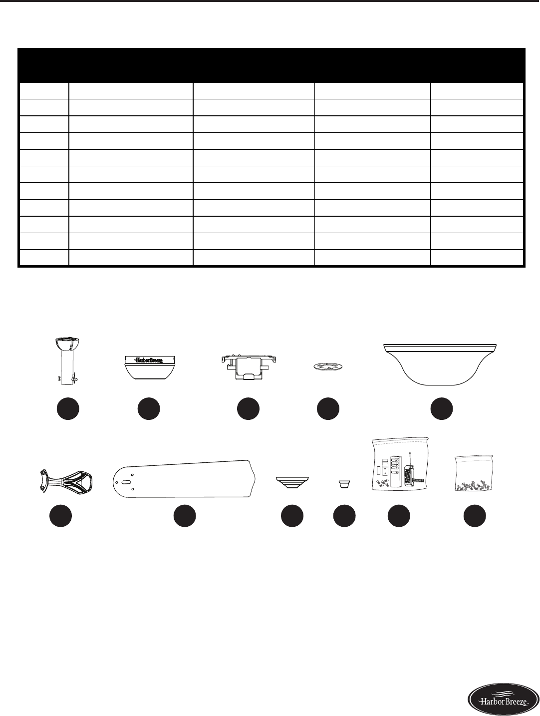
REPLACEMENT PARTS LIST
For replacement parts, call the customer service department at 1-800-643-0067, 8 a.m. - 6 p.m., EST,
Monday - Thursday, 8 a.m. - 5 p.m., EST, Friday.
PART DESCRIPTION
#0599849
PART #
#0599656
PART #
#0599848
PART #
A Downrod 0599849-A 0599656-A 0599848-A
D Canopy 0599849-D 0599656-D 0599848-D
E Mounting Bracket 0599849-E 0599656-E 0599848-E
F Canopy Cover 0599849-F 0599656-F 0599848-F
K Finial Cap 0599849-K 0599656-K 0599848-K
L Finial 0599849-L 0599656-L 0599848-L
M Glass Bowl 0599849-M 0599656-M 0599848-M
NBlade Arm 0599849-N 0599656-N 0599848-N
O Blade 0599849-O 0599656-O 0599848-O
P Remote Pack 0599849-P 0599656-P 0599848-P
HW Hardware Kit 0599849-HW 0599656-HW 0599848-HW
9085•072314
M
K L P HW
DA FE
N O

WARNING:
This device complies with Industry Canada licence-exempt RSS standard(s).
Operation is subject to the following two conditions: (1) this device may not
cause interference, and (2) this device must accept any interference, including
interference that may cause undesired operation of the device.
Le présent appareil est conforme aux CNR d'Industrie Canada applicables aux
appareils radio exempts de licence. L'exploitation est autorisée aux deux
conditions suivantes : (1) l'appareil ne doit pas produire de brouillage, et
(2) l'utilisateur de l'appareil doit accepter tout brouillage radioélectrique
subi, même si le brouillage est susceptible d'en compromettre le fonctionnement.
This device complies with part 15 of the FCC Rules. Operation is subject to the
following two conditions: (1) This device may not cause harmful interference,
and (2) this device must accept any interference received, including
interference that may cause undesired operation.
This equipment has been tested and found to comply with the limits for a Class
B digital device, pursuant to part 15 of the FCC Rules. These limits are designed
to provide reasonable protection against harmful interference in a residential
installation. This equipment generates, uses and can radiate radio frequency
energy and, if not installed and used in accordance with the instructions, may
cause harmful interference to radio communications. However, there is no
guarantee that interference will not occur in a particular installation. If this
equipment does cause harmful interference to radio or television reception,
which can be determined by turning the equipment off and on, the user is
encouraged to try to correct the interference by one or more of the following
measures:
—Reorient or relocate the receiving antenna.
—Increase the separation between the equipment and receiver.
—Connect the equipment into an outlet on a circuit different from that to which
the receiver is connected.
—Consult the dealer or an experienced radio/TV technician for help.
Caution: Any changes or modifications not expressly approved by the party
responsible for compliance could void the user's authority to operate the
equipment.