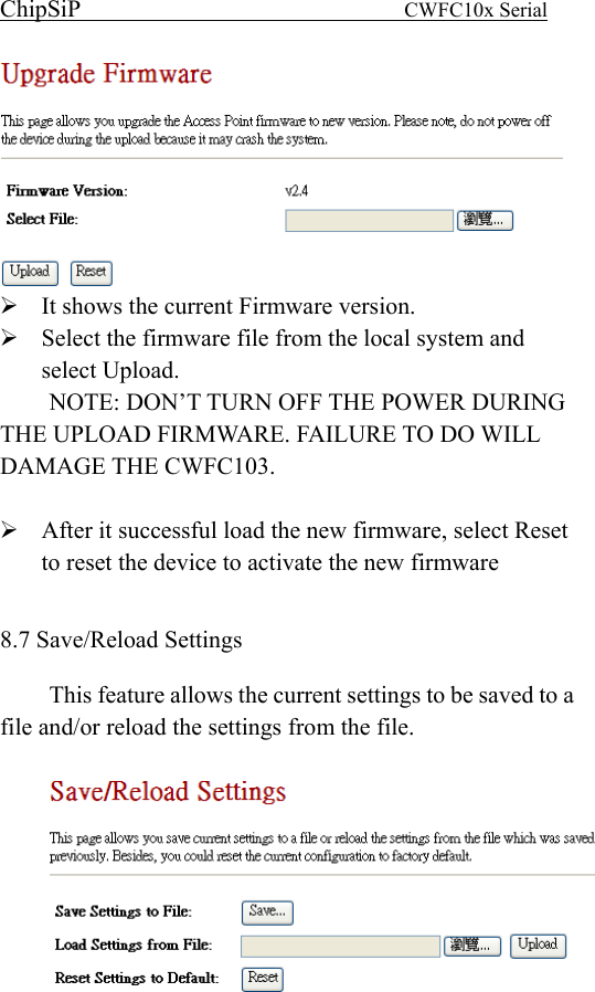
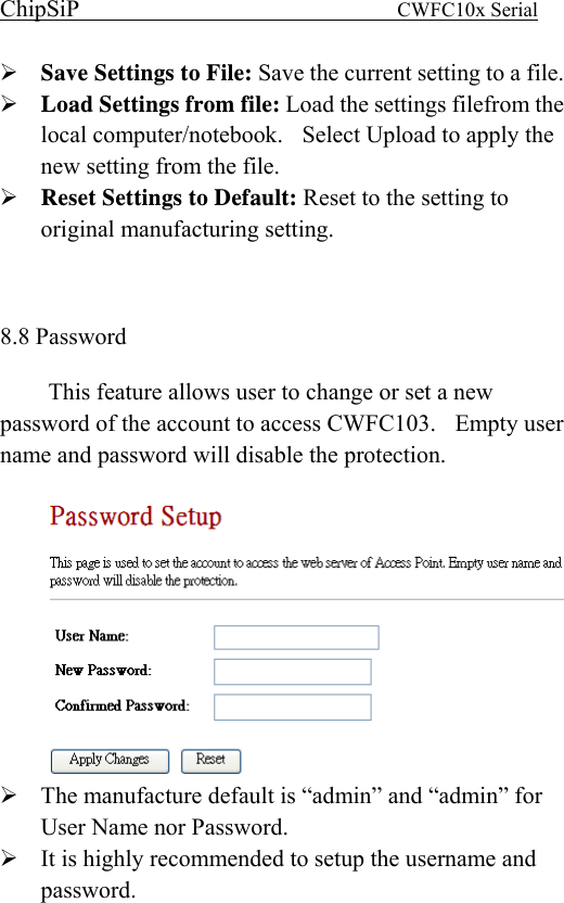
ChipSiP Technology CWFC10X-XXX WiFi b/g/n AP Router User Manual
ChipSiP Technology Co.,Ltd. WiFi b/g/n AP Router
UserManual.wiki
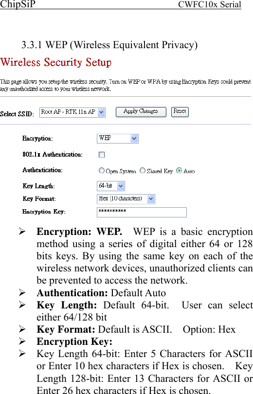
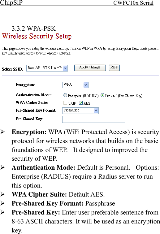
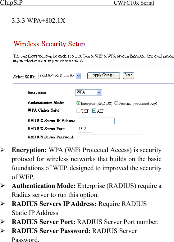
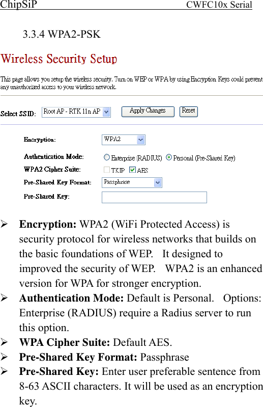
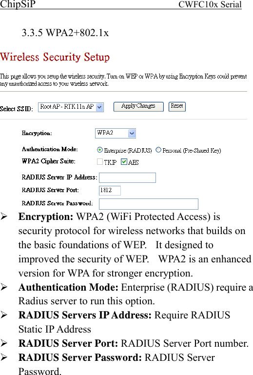
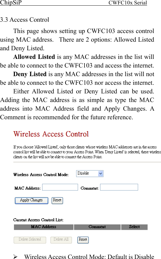
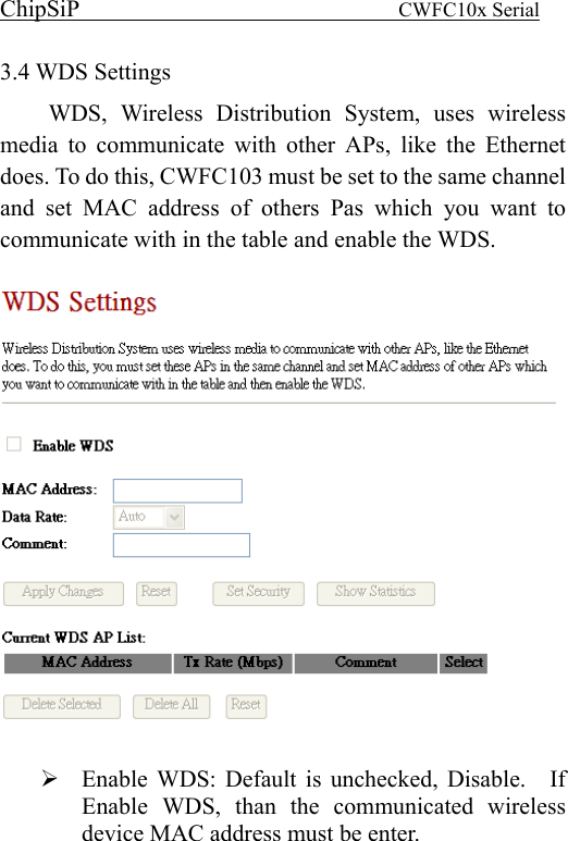
>
ChipSiP Technology
>
CWFC10X XXX User Manual
User manual
Navigation menu
Upload a User Manual
Namespaces
Wiki Guide
HTML
PDF
Info
Views
User Manual
Discussion / Help
Navigation