ChipSiP Technology CWFC10X-XXX WiFi b/g/n AP Router User Manual
ChipSiP Technology Co.,Ltd. WiFi b/g/n AP Router
User manual

ChipSiP CWFC10x Serial
CWF10x Serial
AP/Client/Router
With
2LANs

ChipSiP CWFC10x Serial
Copyright Statement
Trademarks
Copyright @2010
Contents are subject to change without notice.
All trademarks belong to their respective proprietors.
Copyright Statement
THIS DOCUMENT CONTAINS OF PROPRIETARY TECHNICAL
INFORMATION THAT IS THE PROPERTY OF THIS COMPANY. AND
NO PART OF THIS DOCUMENTATION MAY BE REPRODUCED,
STORED IN A RETRIEVAL SYSTEM OR TRANSMITTED IN ANY
FORM OR BY ANY MEANS, ELECTRICAL OR MECHANICAL, BY
PHOTOCOPYING, RECORDING, OR OTHERWISE, WITHOUT THE
PRIOR WRITTEN CONSENT OF THIS COMPANY.

ChipSiP CWFC10x Serial
Contents
CHAPTER 1 INTRODUCTION.........................................5
1.1 INTRODUCTION..............................................................5
1.2 HARDWARE FEATURES ..................................................6
1.3 SOFTWARE FEATURES ....................................................7
1.4 PACKAGE CONTENTS......................................................8
CHAPTER 2 HARDWARE INSTALLATION ..................9
2.1 HOW TO INSTALL THE ROUTER ......................................9
2.2 LED INDICATOR AND PORT DESCRIPTION ...................10
2.3 3 POSITION SLIDE SWITCH...........................................10
CHAPTER 3 WIRELESS SETUP ....................................11
3.1 DEFAULT CONFIGURATION .......................................... 11
3.2 CONFIGURE CWFC103 ...............................................12
3.3 SECURITY SETTING......................................................16
3.3 ACCESS CONTROL .......................................................23
3.4 WDS SETTINGS ...........................................................24
3.5 SITE SURVEY ...............................................................25
3.6 WPS............................................................................26
3.7 WIRELESS SCHEDULE ..................................................26
CHAPTER 4 TCP/IP SETTINGS.....................................28
4.1 LAN INTERFACE .........................................................28
4.2 WAN INTERFACE ........................................................29
CHAPTER 5 FIREWALL .................................................45
5.1. PORT FILTERING .........................................................45
5.2. IP FILTERING ..............................................................46
5.3 MAC FILTERING..........................................................48
5.4 PORT FORWARDING......................................................49
5.5 URL FILTERING...........................................................51
5.6 DMZ ...........................................................................52

ChipSiP CWFC10x Serial
5.7 VLAN SETTINGS.........................................................53
CHAPTER 6 ROUTING SETUP......................................55
6.1 QOS.............................................................................55
6.2 ROUTING .....................................................................57
CHAPTER 8 SYSTEM MAINTENANCES.....................59
8.1 STATUS ........................................................................59
8.2 STATISTICS ...................................................................60
8.3 DDNS .........................................................................61
8.4 TIME ZONE SETTING....................................................62
8.5 DOS.............................................................................63
8.6 SYSTEM LOG ...............................................................64
8.6 UPGRADE FIRMWARE...................................................65
8.7 SAV E /RELOAD SETTINGS .............................................66
8.8 PASSWORD...................................................................67

ChipSiP CWFC10x Serial
Chapter 1 Introduction
1.1 Introduction
Thank you for purchasing CWFC103 Mobile
Multi-purpose Wireless device.
CWFC103 is a portable wireless AP/Router with up to
300Mbps transmission rate. It supports five working modes:
wireless AP (access point), Client+AP, WDS+AP, WISP
Router and Wireless Router.
The default mode is wireless Router. Wireless mode
can be easily switched by sliding the side switch. There are 3
modes: Router, AP, and Client mode.
CWFC103 can be powered from either AC/DC 5V 0.5A
adapter or a computer/Notebook with USB port.

ChipSiP CWFC10x Serial
1.2 Hardware Features
Standard IEEE 802.11b/g/n standards compliant
Wireless LAN 2T2R Mode
Antenna External 0dB antenna
Interface 2 RJ45 (1LAN, 1WAN)
1 USB
Reset/WPS button
Slide switch to select Router, AP, or
client mode
Frequency
Range
2.400 ~ 2.4835 GHz (subject to local
regulations)
Number of
Selectable
Channels
802.11n 20MHz/40MHz
802.11b/g
USA, Canada (FCC); 11 channels
(2.412GHz ~2.462GHz)
Europe (CE): 13 channesl
(2.41GHz!2.472GHz)
Japan (TELEC): 14 channels
(2.41GHz~2.4835GHz)
Data Rate 802.11n: up to 300Mbps
802.11g: 6,9,12,18,24,36,48,54Mbps
802.11b: 1,2,5.5, 11Mbps
Coverage Area Up to 6 times faster than existing
802.11b/g product
Transmit Power 11n HT40 MCS7 : +13.5dBm
11b CCK: +17.5dBm
11g OFDM: +13.5dBm
Receiver
Sensitivity
-66dBm at HT40 MCS7
-73dBm at 54Mpbs
-86dBm at 11Mpbs
LED Power, WPS, Wireless LAN, WAN

ChipSiP CWFC10x Serial
1.3 Software Features
WAN DHCP Client
Static IP
PPPoE (for ADSL)
L2TP
PPTP
Networking DHCP Client/Relay/Server
Dynamic DNS
NTP Client
DNS Cache/Proxy
Firewall:
MAC/IP/Port Filter
Virtual Server
DMZ
Content Filter
WIFI 1 Transmit and 1 Receive paths (1T1R)
20MHz/40MHz bandwidth
Support Multiple SSID
Support Hidden SSID
Support WPS
Clock rate up to 400MHz Legacy and High
Throughput Modes
High security: WEP64/128,TKIP,
WPA,WPA2 AES,mixed, 802.11i
802.1X Authentication with RADIUS
Client
QoS-WMM, WMM-PS

ChipSiP CWFC10x Serial
1.4 Package contents
The package contains the following items
1 CWFC103
1 AC/DC Adapter
Input: 110~240V 50/60Hz,
Output: 5V 500mA adapter
1 One quick installation guide
1 CD
1 Ethernet cable
1 USB cable
ChipSiP CWFC10x Serial
Chapter 2 Hardware Installation
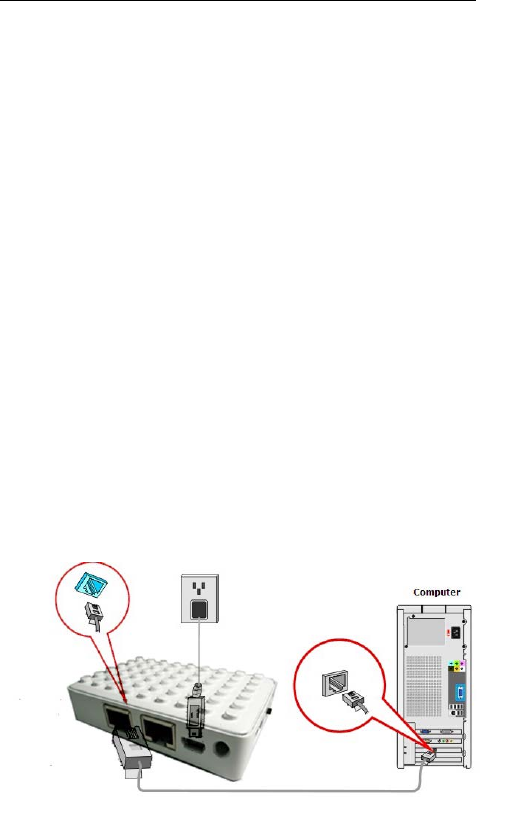
2.1 How to Install the Router
After you unpack the box, please make sure all the
components are completed.
Follow the below setup to setup the CWFC103:
1. Connect the Ethernet cable to the CWFC103 WAN
port
2. Connect the other end of the Ethernet cable to the
device (for example ADSL)
3. Connect the miniUSB power cord to the CWFC103
miniUSB power
4. Connect the AC/DC adapter to the wall or power
extension cord
Power Supply: Please use the power adapter from the package
to power on the CWFC103. (IMPORTANT: Use of a different
power adapter could damage the CWFC103.)

ChipSiP CWFC10x Serial
2.2 LED Indicator and Port Description
LED indicators description on front panel: (From R to L)
1. PWR:Indicates CWFC103 is power on.
2. WPS: Flashing indicates CWFC103 is negotiating
with the client in WPS mode.
3. WL: Indicates the WIRELESS LAN is
connected.
4. WAN: Indicates an Ethernet cable is connected
into WAN port.
5. LAN: Indicate an Ethernet cable is connected into
the LAN port.
2.3 3 Position Slide Switch
Left: AP/Bridge Mode
Middle: Client/Bridge Mode
Right: Router Mode

ChipSiP CWFC10x Serial
Chapter 3 Wireless Setup
This chapter is to describe how to configure CWFC103
to setup different modes: Gateway, AP/Bridge and Wireless
ISP mode.
Operation Mode:
Gateway: In this mode, the device is supposed
to connect to internet via ADSL/Cable modem.
The NAT is enabled and PCs in LAN ports
share the same IP to ISP through WAN port.
The connection type can be setup in WAN page
by using PPPoE, DHCP client, PPTP client,
L2TP client or static IP.
Bridge: In this mode, all Ethernet ports and
wireless interface are bridged together and
NAT function is disabled. All the WAN
related function and firewall are not supported.
3.1 Default Configuration
IP address 10.10.1.1
Subnet mask 255.255.255.0
Username admin
Password admin
Operation Mode Gateway
DHCP On
SSID AsiaRF 11n
ChipSiP CWFC10x Serial
Channel Smart select
Security Off
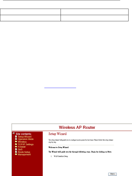
3.2 Configure CWFC103
1. Connect the Ethernet cable to the CWFC103 LAN
port and your notebook/computer.
2. Power up to CWFC103.
3. Open Internet Explorer from your
notebook/computer
4. Enter: http://10.10.1.1
5. Enter the Username and Password. If this is the
first time use, than enter “admin” and “admin” on
both username and password.
6. The following screen will show up and follow the
instruction
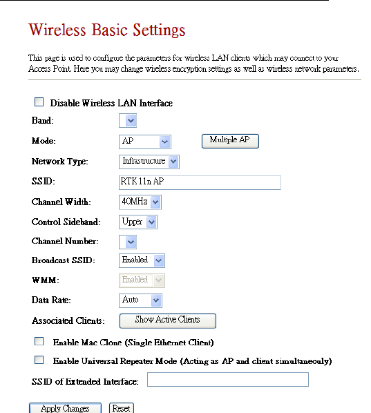
3.2.1 Basic Settings
This page is used to configure the basic parameters for
the wireless LAN.
ChipSiP CWFC10x Serial
Disable Wireless LAN Interface: Default is uncheck
(Enable). Check to Disable the Wireless function.
Mode: Default Gateway. There are 3 modes: Gateway,
AP, Client mode.
Network Type: Default is Infrastructure. There are 2
types: Infrastructure and AD HOC. Infrastructure is
the standard wifi mode. AD HOC mode is for Peer to

ChipSiP CWFC10x Serial
Peer connection.
SSID: Service Set Identifier is an unique name of the
CWFC103 in the wireless network. Wireless client to
connect to the wireless network using SSID.
Channel Width: Default is 20/40MHz. The channel
bandwidth is to improve the wireless performance.
40MHz can be selected for 11b/g and 11n client.
20/40Mhz is recommended for 11n network to improve
the throughput.
Channel Number: Default is Auto. The effective
channel from 1 to 13/Auto of the wireless network.
3.2.2 Wireless Advance Settings
Broadcast SSID: Default is Enable. The device’s
SSID is visible to wireless clients.
WMM: Default is Enabled. It will enhance the
multimedia data transfer performance.
Data Rate: Default is Auto. CWFC103 will negotiate
will wireless client for best performance.
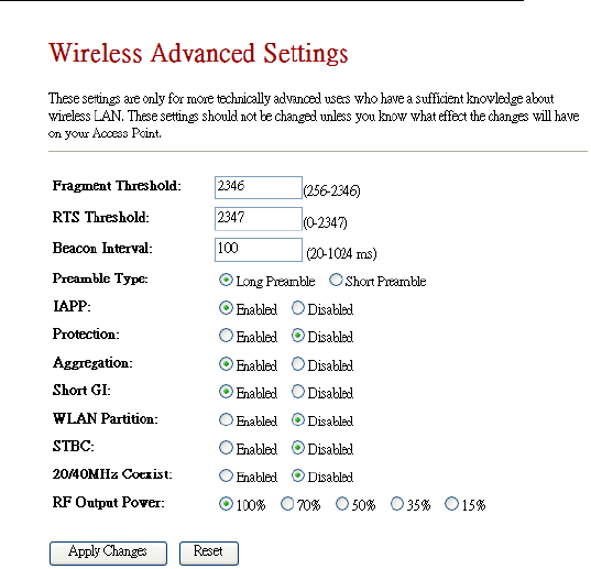
3.2.2 Advance Wireless Settings
THESE SETTINGS ARE ONLY FOR MORE
TECHNICALLY ADVANCED USERS WHO HAVE A
SUFFICIENT KNOWLEDGE ABOUT WIRELESS LAN.
IMPROPER SETTING MAY CAUSE CWFC103 DOES
NOT FUNCTION.
ChipSiP CWFC10x Serial
Fragment Threshold: Default is 2346. The
fragmentation threshold defines the maximum
transmission packet size in bytes. The packet will be
fragmented if the arrival is bigger than the threshold
setting.
RTS Threshold: Default is 2347. RTS stands for
“Request to Send”. This parameter controls what size
data packet the frequency protocol issues RTS packet.
Beacon Interval: Default is 100. Set the beacon
interval of wireless radio.
Preamble Type: Default is Long
ChipSiP CWFC10x Serial
IAPP: Default is Enabled
Protection: Default is Disable
Aggregation: Default is Enabled
Short GI: Default is Enabled
WLAN Partition: Default is Disabled
STBC: Default is Disabled
20/40MHz Coexist: Default is Disabled
RF Output Power: Default is 100%
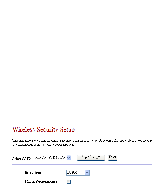
3.3 Security Setting
This page shows setting up the security of the
CWFC103. Turning on the CWFC103 security will
prevent any unauthorized access to the wireless network.
ChipSiP CWFC10x Serial
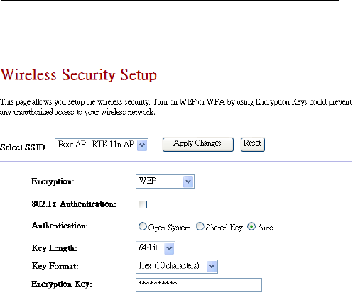
3.3.1 WEP (Wireless Equivalent Privacy)
Encryption: WEP. WEP is a basic encryption
method using a series of digital either 64 or 128
bits keys. By using the same key on each of the
wireless network devices, unauthorized clients can
be prevented to access the network.
Authentication: Default Auto
Key Length: Default 64-bit. User can select
either 64/128 bit
Key Format: Default is ASCII. Option: Hex
Encryption Key:
Key Length 64-bit: Enter 5 Characters for ASCII
or Enter 10 hex characters if Hex is chosen. Key
Length 128-bit: Enter 13 Characters for ASCII or
Enter 26 hex characters if Hex is chosen.
ChipSiP CWFC10x Serial
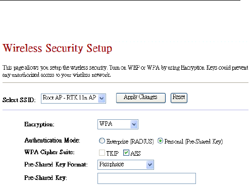
3.3.2 WPA-PSK
Encryption: WPA (WiFi Protected Access) is security
protocol for wireless networks that builds on the basic
foundations of WEP. It designed to improved the
security of WEP.
Authentication Mode: Default is Personal. Options:
Enterprise (RADIUS) require a Radius server to run
this option.
WPA Cipher Suite: Default AES.
Pre-Shared Key Format: Passphrase
Pre-Shared Key: Enter user preferable sentence from
8-63 ASCII characters. It will be used as an encryption
key.
ChipSiP CWFC10x Serial
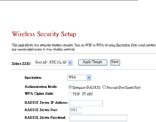
3.3.3 WPA+802.1X
Encryption: WPA (WiFi Protected Access) is security
protocol for wireless networks that builds on the basic
foundations of WEP. designed to improved the security
of WEP.
Authentication Mode: Enterprise (RADIUS) require a
Radius server to run this option.
RADIUS Servers IP Address: Require RADIUS
Static IP Address
RADIUS Server Port: RADIUS Server Port number.
RADIUS Server Password: RADIUS Server
Password.
ChipSiP CWFC10x Serial
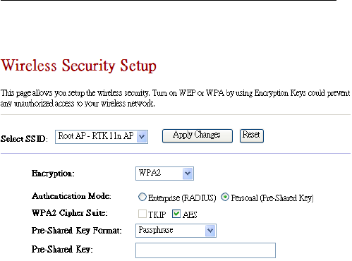
3.3.4 WPA2-PSK
Encryption: WPA2 (WiFi Protected Access) is
security protocol for wireless networks that builds on
the basic foundations of WEP. It designed to
improved the security of WEP. WPA2 is an enhanced
version for WPA for stronger encryption.
Authentication Mode: Default is Personal. Options:
Enterprise (RADIUS) require a Radius server to run
this option.
WPA Cipher Suite: Default AES.
Pre-Shared Key Format: Passphrase
Pre-Shared Key: Enter user preferable sentence from
8-63 ASCII characters. It will be used as an encryption
key.
ChipSiP CWFC10x Serial
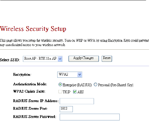
3.3.5 WPA2+802.1x
Encryption: WPA2 (WiFi Protected Access) is
security protocol for wireless networks that builds on
the basic foundations of WEP. It designed to
improved the security of WEP. WPA2 is an enhanced
version for WPA for stronger encryption.
Authentication Mode: Enterprise (RADIUS) require a
Radius server to run this option.
RADIUS Servers IP Address: Require RADIUS
Static IP Address
RADIUS Server Port: RADIUS Server Port number.
RADIUS Server Password: RADIUS Server
Password.
ChipSiP CWFC10x Serial
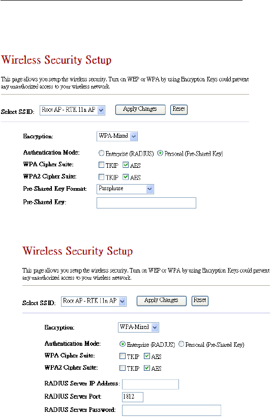
3.3.6 WPA-Mixed-PSK
3.3.7 WPA-Mixed+802.1x
ChipSiP CWFC10x Serial
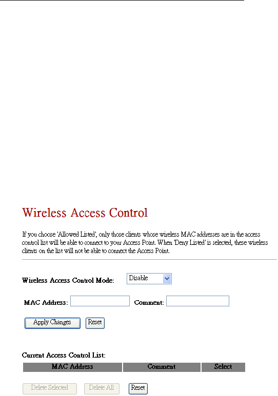
3.3 Access Control
This page shows setting up CWFC103 access control
using MAC address. There are 2 options: Allowed Listed
and Deny Listed.
Allowed Listed is any MAC addresses in the list will
be able to connect to the CWFC103 and access the internet.
Deny Listed is any MAC addresses in the list will not
be able to connect to the CWFC103 nor access the internet.
Either Allowed Listed or Deny Listed can be used.
Adding the MAC address is as simple as type the MAC
address into MAC Address field and Apply Changes. A
Comment is recommended for the future reference.
Wireless Access Control Mode: Default is Disable
ChipSiP CWFC10x Serial
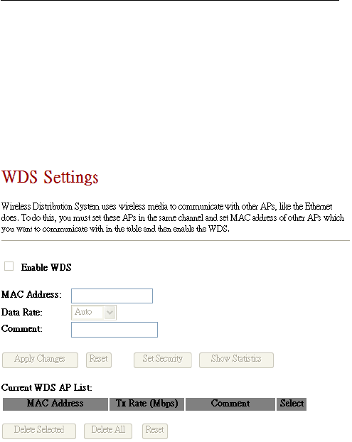
3.4 WDS Settings
WDS, Wireless Distribution System, uses wireless
media to communicate with other APs, like the Ethernet
does. To do this, CWFC103 must be set to the same channel
and set MAC address of others Pas which you want to
communicate with in the table and enable the WDS.
Enable WDS: Default is unchecked, Disable. If
Enable WDS, than the communicated wireless
device MAC address must be enter.
ChipSiP CWFC10x Serial
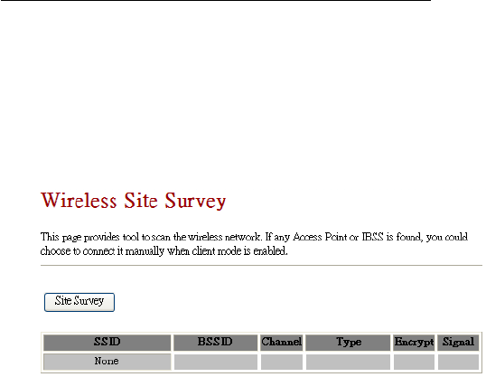
3.5 Site Survey
This page provides a tool to scan any accessible
wireless network. If there is an Access Point or IBSS , than
you can connect manually using CWFC103 as a client
mode.

ChipSiP CWFC10x Serial
3.6 WPS
This page to show setup the WPS (WiFi Protected
Setup) mode. This feature will allow a client with WPS
feature on automatically synchronize with CWFC103
setting and connect to the CWFC103. A Self-PIN is
required or press the button on the back CWFC103 panel.
Disable WPS: Default is uncheck. Enable WPS
function
Client PIN Number: Must be entered a PIN. A
wireless client must enter the same PIN in order to
to synchronous with CWFC103.
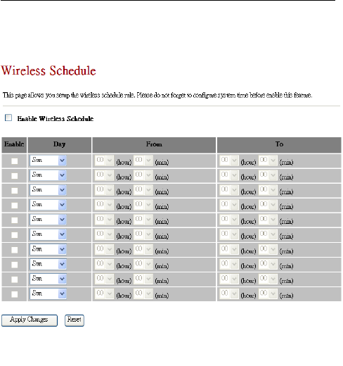
3.7 Wireless Schedule
This page to show setting up the wireless schedule
rule.
ChipSiP CWFC10x Serial
DO NOT FORGET TO CONFIGURE SYSTEM TIME
BEFORE ENABLE THIS FEATURE.
Enable Wireless Schedule: Default is Disable.
ChipSiP CWFC10x Serial
Chapter 4 TCP/IP Settings
This Chapter is to present how to configure the LAN and
Wireless TCP/IP setup.
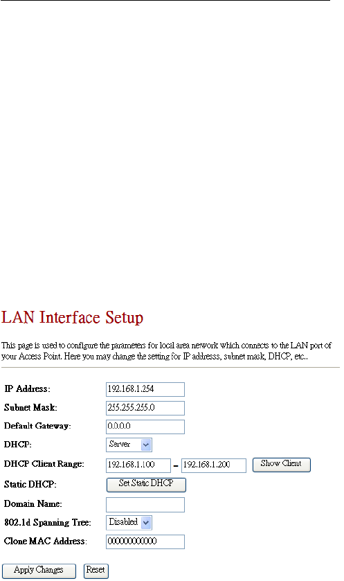
4.1 LAN Interface
The section is to show how to configure the
parameters for local area network connected to the LAN
port of the CWFC103. You can configure the IP addresses,
subnet mask, DHCP,…etc.

ChipSiP CWFC10x Serial
IP Address: Default is 10.10.1.1. It can be
changed to any preferable IP address
Subnet Mask: Default is 255.255.255.0. This
field is related to the IP address
Default Gateway: Default is 0.0.0.0. If there is no
input in this field, than it will use the default IP
address for the default gateway address
DHCP: Default is Server. If select DHCP is
server, than it will generate the IP address within
the DHCP Client Range for the clients
DHCP Client Range: Default is 10.10.1.100 to
10.10.1.200. If a different IP range
Static DHCP: It can be set to Static DHCP
Domain Name: A domain name can be entered
802.1d Spanning Tree: Default is Disabled.
Spanning Tree will ensures a loop-free topology
for any bridged local area network. The loop
won’t happen under normal use. Hence it is
recommended to disable this option
Clone MAC Address: Fill in the MAC address
that is the MAC address to be cloned.
Apply Changes: Click the Apply Changes button
to complete the new configuration setting.
Reset: Click the Reset button to abort change and
recover the previous configuration setting.
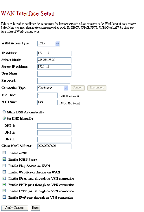
4.2 WAN Interface
This page is used to configure the parameters for
Internet network which connects to the WAN port of
CWFC103. User can configure the access method to static
IP, DHCP,PPPoE, PPTP, or L2TP by selecting the item
ChipSiP CWFC10x Serial
value of the WAN access type.
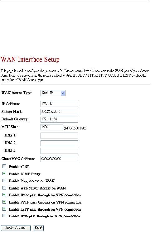
4.2.1 Static IP
WAN Access Type: Select Static IP as WAN access
type.
Static IP: Click to select Static IP support on WAN

ChipSiP CWFC10x Serial
interface. There are IP address, subnet mask and default
gateway settings need to be done.
IP Address: If you select the Static IP support on WAN
interface, fill in the IP address for it.
Subnet Mask: If you select the Static IP support on
WAN interface, fill in the subnet mask for it.
Default Gateway: If you select the Static IP support on
WAN interface, fill in the default gateway for WAN
interface out going data packets.
MTU Size Fill in the mtu size of MTU Size. The
default value is 1500
Set DNS Manually: Click to select getting DNS
address for Static IP support.
DNS 1: Fill in the IP address of Domain Name Server
1.
DNS 2: Fill in the IP address of Domain Name Server
2.
DNS 3: Fill in the IP address of Domain Name Server
3.
Clone MAC Address: Fill in the MAC address that is
the MAC address to be cloned.
Enable uPNP: Click the checkbox to enable uPNP
function.
Enable IGMP Proxy: Click the checkbox to enable
IGMP Proxy.
Enable Ping Access on WAN: Click the checkbox to
enable WAN ICMP response.
Enable Web Server Access on WAN: Click the
checkbox to enable web configuration from WAN side.
Enable FTP Server Access on WAN: Click the
checkbox to enable FTP Server Access on WAN
Enable IPsec pass through on VPN connection:
Click the checkbox to enable IPSec packet pass through

ChipSiP CWFC10x Serial
Enable PPTP pass through on VPN connection:
Click the checkbox to enable PPTP packet pass through
Enable L2TP pass through on VPN connection:
Click the checkbox to enable L2TP packet pass through
Apply Changes: Click the Apply Changes button to
complete the new configuration setting.
Reset: Click the Reset button to abort change and
recover the previous configuration setting.
ChipSiP CWFC10x Serial
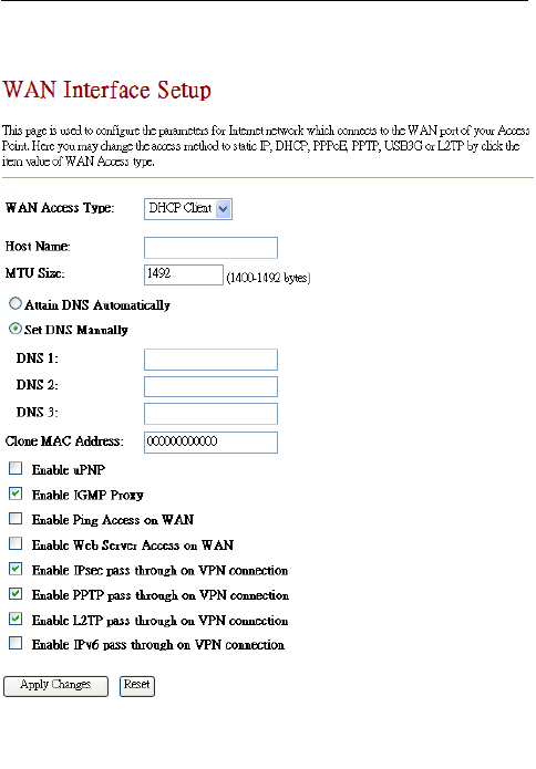
4.2.2 DHCP
DHCP Client: Click to select DHCP support on WAN
interface for IP address assigned automatically from a
DHCP server.
Host Name: Fill in the host name of Host Name. The
default value is empty
MTU Size Fill in the mtu size of MTU Size. The default
value is 1500
Attain DNS Automatically: Click to select getting

ChipSiP CWFC10x Serial
DNS address automatically.
Set DNS Manually: Click to select getting DNS
address for Static IP support.
DNS 1: Fill in the IP address of Domain Name Server
1.
DNS 2: Fill in the IP address of Domain Name Server
2.
DNS 3: Fill in the IP address of Domain Name Server
3.
Clone MAC Address: Fill in the MAC address that is
the MAC address to be cloned.
Enable uPNP: Click the checkbox to enable uPNP
function.
Enable IGMP Proxy: Click the checkbox to enable
IGMP Proxy.
Enable Ping Access on WAN: Click the checkbox to
enable WAN ICMP response.
Enable Web Server Access on WAN: Click the
checkbox to enable web configuration from WAN side.
Enable FTP Server Access on WAN: Click the
checkbox to enable FTP Server Access on WAN
Enable IPsec pass through on VPN connection:
Click the checkbox to enable IPSec packet pass through
Enable PPTP pass through on VPN connection:
Click the checkbox to enable PPTP packet pass through
Enable L2TP pass through on VPN connection:
Click the checkbox to enable L2TP packet pass through
Apply Changes: Click the Apply Changes button to
complete the new configuration setting.
Reset: Click the Reset button to abort change and
recover the previous configuration setting.
ChipSiP CWFC10x Serial
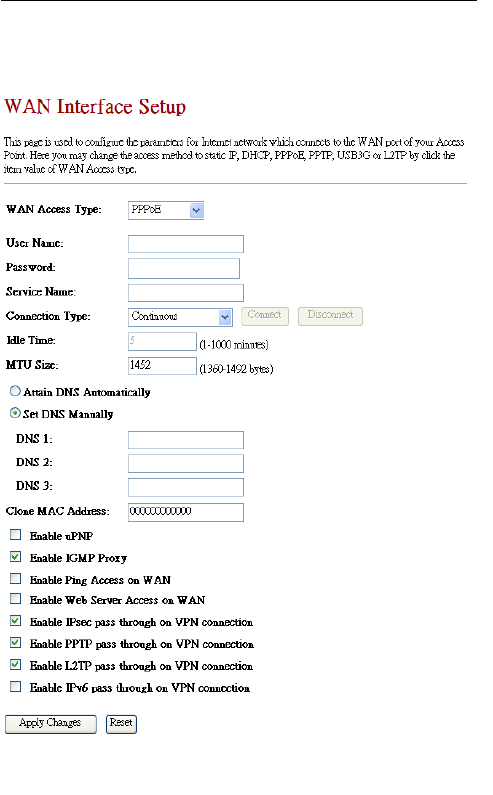
4.2.3 PPPoE
PPPoE: Click to select PPPoE support on WAN
interface. There are user name, password, connection
type and idle time settings need to be done.
User Name: If you select the PPPoE support on WAN

ChipSiP CWFC10x Serial
interface, fill in the user name and password to login the
PPPoE server.
Password: If you select the PPPoE support on WAN
interface, fill in the user name and password to login the
PPPoE server.
Service Name: Fill in the service name of Service
Name. The default value is empty.
Connection Type: Select the connection type from
pull-down menu. There are Continuous, Connect on
Demand and Manual three types to select.
Idle Time: If you select the PPPoE and Connect on
Demand connection type, fill in the idle time for
auto-disconnect function. Value can be between 1 and
1000 minutes.
Host Name: Fill in the host name of Host Name. The
default value is empty
MTU Size: Fill in the mtu size of MTU Size. The
default value is 1500
Attain DNS Automatically: Click to select getting
DNS address automatically.
Set DNS Manually: Click to select getting DNS
address for Static IP support.
DNS 1: Fill in the IP address of Domain Name Server
1.
DNS 2: Fill in the IP address of Domain Name Server
2.
DNS 3: Fill in the IP address of Domain Name Server
3.
Clone MAC Address: Fill in the MAC address that is
the MAC address to be cloned.
Enable uPNP: Click the checkbox to enable uPNP
function.
Enable IGMP Proxy: Click the checkbox to enable

ChipSiP CWFC10x Serial
IGMP Proxy.
Enable Ping Access on WAN: Click the checkbox to
enable WAN ICMP response.
Enable Web Server Access on WAN: Click the
checkbox to enable web configuration from WAN side.
Enable FTP Server Access on WAN: Click the
checkbox to enable FTP Server Access on WAN
Enable IPsec pass through on VPN connection:
Click the checkbox to enable IPSec packet pass through
Enable PPTP pass through on VPN connection:
Click the checkbox to enable PPTP packet pass through
Enable L2TP pass through on VPN connection:
Click the checkbox to enable L2TP packet pass through
Apply Changes: Click the Apply Changes button to
complete the new configuration setting.
Reset: Click the Reset button to abort change and
recover the previous configuration setting.
ChipSiP CWFC10x Serial
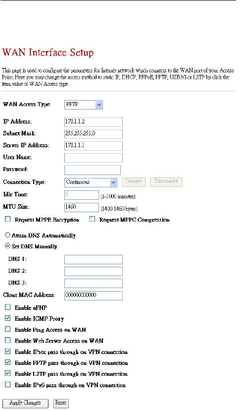
4.2.4 PPTP

ChipSiP CWFC10x Serial
PPTP: PPTP Allow user to make a tunnel with remote
site directly to secure the data transmission among the
connection. User can use embedded PPTP client
supported by this router to make a VPN connection.
Enable Dynamic Mode: Click to select PPTP
Dynamic support on WAN interface for IP address
assigned automatically from a PPTP server.
IP Address: If you select the PPTP support on WAN
interface, fill in the IP address for it.
Subnet Mask: If you select the PPTP support on WAN
interface, fill in the subnet mask for it.
Gateway: If you select the Static PPTP support on
WAN interface, fill in the gateway for WAN interface
out going data packets.
Server IP Address: Enter the IP address of the PPTP
Server.
Server Domain Name: Assign Domain Name and
dispatch to PPTP servers. It is optional field.
User Name: If you select the PPTP support on WAN
interface, fill in the user name and password to login the
PPTP server.
Password: If you select the PPTP support on WAN
interface, fill in the user name and password to login the
PPTP server.
MTU Size: Fill in the mtu size of MTU Size. The
default value is 1500
Attain DNS Automatically: Click to select getting
DNS address automatically.
Set DNS Manually: Click to select getting DNS
address for Static IP support.
DNS 1: Fill in the IP address of Domain Name Server
1.
DNS 2: Fill in the IP address of Domain Name Server

ChipSiP CWFC10x Serial
2.
DNS 3: Fill in the IP address of Domain Name Server
3.
Clone MAC Address: Fill in the MAC address that is
the MAC address to be cloned.
Enable uPNP: Click the checkbox to enable uPNP
function.
Enable IGMP Proxy: Click the checkbox to enable
IGMP Proxy.
Enable Ping Access on WAN: Click the checkbox to
enable WAN ICMP response.
Enable Web Server Access on WAN: Click the
checkbox to enable web configuration from WAN side.
Enable FTP Server Access on WAN: Click the
checkbox to enable FTP Server Access on WAN
Enable IPsec pass through on VPN connection:
Click the checkbox to enable IPSec packet pass through
Enable PPTP pass through on VPN connection:
Click the checkbox to enable PPTP packet pass through
Enable L2TP pass through on VPN connection:
Click the checkbox to enable L2TP packet pass through
Apply Changes: Click the Apply Changes button to
complete the new configuration setting.
Reset: Click the Reset button to abort change and
recover the previous configuration setting.
4.2.5 L2TP
ChipSiP CWFC10x Serial
L2TP: L2TP Allow user to make a tunnel with remote
site directly to secure the data transmission among the
connection. User can use embedded L2TP client
supported by this router to make a VPN connection.

ChipSiP CWFC10x Serial
IP Address: If you select the L2TP support on WAN
interface, fill in the IP address for it.
Subnet Mask: If you select the L2TP support on WAN
interface, fill in the subnet mask for it.
Gateway: If you select the Static L2TP support on
WAN interface, fill in the gateway for WAN interface
out going data packets.
Server IP Address: Enter the IP address of the L2TP
Server.
User Name: If you select the PPTP support on WAN
interface, fill in the user name and password to login the
PPTP server.
Password: If you select the PPTP support on WAN
interface, fill in the user name and password to login the
PPTP server.
MTU Size: Fill in the mtu size of MTU Size. The
default value is 1500
Attain DNS Automatically: Click to select getting
DNS address automatically.
Set DNS Manually: Click to select getting DNS
address for Static IP support.
DNS 1: Fill in the IP address of Domain Name Server
1.
DNS 2: Fill in the IP address of Domain Name Server
2.
DNS 3: Fill in the IP address of Domain Name Server
3.
Clone MAC Address: Fill in the MAC address that is
the MAC address to be cloned.
Enable uPNP: Click the checkbox to enable uPNP
function.
Enable IGMP Proxy: Click the checkbox to enable
IGMP Proxy.

ChipSiP CWFC10x Serial
Enable Ping Access on WAN: Click the checkbox to
enable WAN ICMP response.
Enable Web Server Access on WAN: Click the
checkbox to enable web configuration from WAN side.
Enable FTP Server Access on WAN: Click the
checkbox to enable FTP Server Access on WAN
Enable IPsec pass through on VPN connection:
Click the checkbox to enable IPSec packet pass through
Enable PPTP pass through on VPN connection:
Click the checkbox to enable PPTP packet pass through
Enable L2TP pass through on VPN connection:
Click the checkbox to enable L2TP packet pass through
Apply Changes: Click the Apply Changes button to
complete the new configuration setting.
Reset: Click the Reset button to abort change and
recover the previous configuration setting.
ChipSiP CWFC10x Serial
Chapter 5 Firewall
This Chapter is guided you how to setup the Firewall for
CWFC103 to secure and prevent unauthorized access of
your local network.
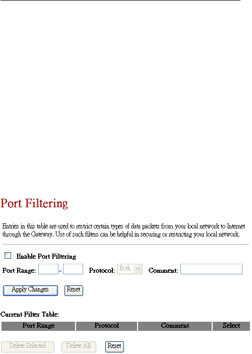
5.1. Port Filtering
Entries in this table are used to restrict certain types of
data packets from your local network to Internet through the
CWFC103. Use such filters can be helpful in securing or
restricting your local network.
Enable Port Filtering: Default is uncheck,
Disable. If the option is enabled, than the Port
Entries in the table will be restricted to access the
network.
Port Range: To restrict data transmission from the

ChipSiP CWFC10x Serial
local network on certain ports, fill in the range of
start-port and end-port, and the protocol, also put
your comments on it.
Protocol: The Protocol can be TCP, UDP or Both.
Comments: Comments let you know about whys
to restrict data from the ports.
Apply Changes: Click the Apply Changes button
to register the client to new configuration setting.
Reset: Click the Reset button to abort change and
recover the previous configuration setting.
Delete Selected: Click to delete the selected clients
that will be access right removed from CWFC103.
Delete All: Click to delete all the registered clients
from the access allowed list.
Reset: Click the Reset button to abort change and
recover the previous configuration setting.
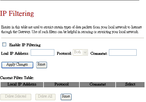
5.2. IP Filtering
Entries in this table are used to restrict certain types of
data packets from your local network to Internet through the
CWFC103. Use such filters can be helpful in securing or
restricting your local network.
ChipSiP CWFC10x Serial
Enable IP Filtering: Default is uncheck, Disable.
If the option is enabled, than the IP Entries in the
table will be restricted to access the network.
Local IP Address: To restrict data transmission
from the local network on certain IP addresses, fill
in the IP address, and the protocol, also put your
comments on it.
Protocol: The Protocol can be TCP, UDP or Both.
ChipSiP CWFC10x Serial
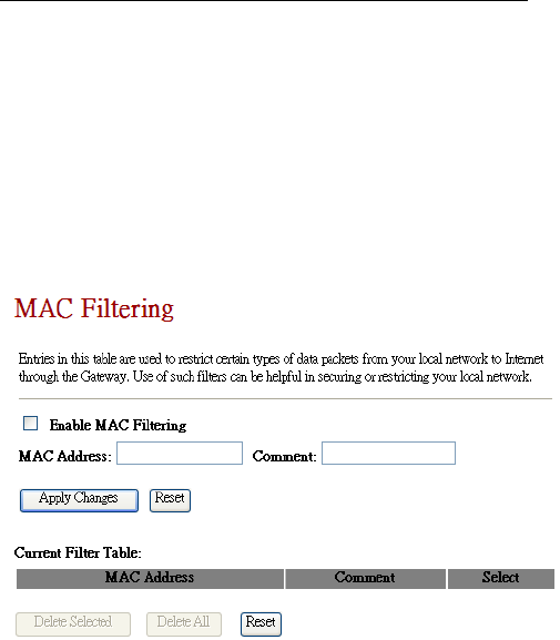
5.3 MAC Filtering
Entries in this table are used to restrict certain types of
data packets from your local network to Internet through the
CWFC103. Use such filters can be helpful in securing or
restricting your local network.
Enable MAC Filtering: Default is uncheck,
Disable. If the option is enabled, than the MAC
Entries in the table will be restricted to access the
network.
MAC Address: To restrict data transmission from
the local network on certain MAC addresses, fill in
the MAC address, also put your comments on it.
Comments: Comments let you know about whys
to restrict data from the ports.

ChipSiP CWFC10x Serial
Apply Changes: Click the Apply Changes button
to register the client to new configuration setting.
Reset: Click the Reset button to abort change and
recover the previous configuration setting.
Delete Selected: Click to delete the selected clients
that will be access right removed from CWFC103.
Delete All: Click to delete all the registered clients
from the access allowed list.
Reset: Click the Reset button to abort change and
recover the previous configuration setting.
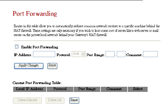
5.4 Port Forwarding
Entries in this table allow you to automatically redirect
common network services to a specific port behind the NAT
firewall. These settings are only necessary if you wish to
host some sort of server like web server or mail server on a
private local network behind CWFC103 NAT firewall.
ChipSiP CWFC10x Serial
Enable Port Forwarding: Default is Unchecked,
Disable. If enable,
IP Address: Enter the IP address of the PC where
the applications are being set.
Protocol: Select the protocol (TCP/UDP/Both) for
the application
Port Range: Enter the start and end port number
which ranges of the external port used to set the
server or internet application.
Apply Changes: Click the Apply Changes button
to register the client to new configuration setting.
Reset: Click the Reset button to abort change and
recover the previous configuration setting.
Delete Selected: Click to delete the selected clients
that will be access right removed from CWFC103.
Delete All: Click to delete all the registered clients
from the access allowed list.
ChipSiP CWFC10x Serial
Reset: Click the Reset button to abort change and
recover the previous configuration setting.
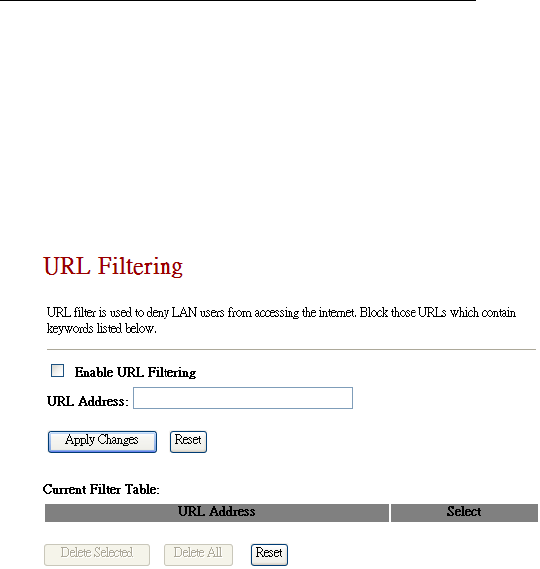
5.5 URL Filtering
URL filter is used to deny LAN users from accessing
the internet. Block those URLs which contain keywords
listed below.
Enable URL Filtering: Default is uncheck,
Disable. If the option is enabled, than the URL
Entries in the table will be restricted to access the
network.
URL Address: Add one URL address.
Apply Changes: Click the Apply Changes button
to register the client to new configuration setting.
Reset: Click the Reset button to abort change and
recover the previous configuration setting.
Delete Selected: Click to delete the selected clients
ChipSiP CWFC10x Serial
that will be access right removed from CWFC103.
Delete All: Click to delete all the registered clients
from the access allowed list.
Reset: Click the Reset button to abort change and
recover the previous configuration setting.
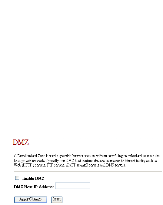
5.6 DMZ
DMZ, Demilitarized Zone, is used to provide Internet
services without sacrificing unauthorized access to its local
private network. Typically, the DMZ host contains devices
accessible to Internet traffic, such as printer server,
Web(HTTP) servers, FTP servers, SMTP (e-mail) servers
and DNS servers.
Enable DMZ: Default is unchecked, Disable. If
enable, than a DMZ Host IP Address must be
entered to expose to Internet.
DMZ Host IP Address: To support DMZ in your
firewall design, fill in the IP address of DMZ host
that can be access from the WAN interface.

ChipSiP CWFC10x Serial
Apply Changes: Click the Apply Changes button
to register the client to new configuration setting.
Reset: Click the Reset button to abort change and
recover the previous configuration setting.
Delete Selected: Click to delete the selected clients
that will be access right removed from CWFC103.
Delete All: Click to delete all the registered clients
from the access allowed list.
Reset: Click the Reset button to abort change and
recover the previous configuration setting.
NOTE: Once the DMA host is enabled, the firewall settings
of the DMZ host will no longer work.
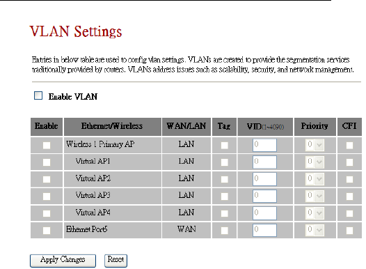
5.7 VLAN Settings
Entries in below table are used to configure VLAN
settings. VLANs are created to provide the segmentation
services traditionally provided by routers. VLANs address
issues such as scalability, security, and network
management.
ChipSiP CWFC10x Serial
Enable VLAN: Default is unchecked, Disable.
Apply Changes: Click the Apply Changes button
to register the client to new configuration setting.
Reset: Click the Reset button to abort change and
recover the previous configuration setting.
Delete Selected: Click to delete the selected clients
that will be access right removed from CWFC103.
Delete All: Click to delete all the registered clients
from the access allowed list.
Reset: Click the Reset button to abort change and
recover the previous configuration setting.

ChipSiP CWFC10x Serial
Chapter 6 Routing Setup
This chapter is to guide how to setup the best path for the
data frame.
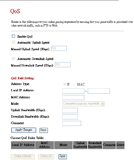
6.1 QoS
QoS, Quality of Service, is the ability to provide
different priority to different applications: multimedia, VoIP
services, online games or IP-TV, users, or data flows, or to
guarantee a certain level of performance to a data flow.
Entries in this table is to setup an improvement of an
online gaming or multi-media experience by ensuring that
game traffic is prioritized over other network traffic such as
FTP or Web.
ChipSiP CWFC10x Serial
Enable QoS: Default is Unchecked, Disable. If
select enable, than continue with the following
Select Automatic Uplink Speed or Manual Uplink
Speed (Kbps). The speed must be entered if
Manual Uplink Speed is selected.
Select Automatic Downlink Speed or Manual

ChipSiP CWFC10x Serial
Downlink Speed (Kbps). The speed must be
entered if Manual Uplink Speed is selected.
Address Type: Default is IP. Another option is
based on MAC
Local IP Address: Enter a range of IP address if IP
is selected in the Address Type
MAC Address: Enter a MAC address of each
client that connect to CWFC103 if MAC is selected
in the Address Type
Mode: Guaranteed minimum bandwidth
Uplink Bandwidth (Kbps): Guarantee has a
minimum uplink bandwidth for the clients
Downlink Bandwidth (Kbps): Guarantee has a
minimum downlink bandwidth for the clients
Apply Changes: Click on this icon after all the
options are fill up
Reset: Click the Reset button to abort change and
recover to the previous configuration setting.
Delete Selected: Click to delete the selected clients
that will be access right removed from CWFC103.
Delete All: Click to delete all the registered clients
from the access allowed list.
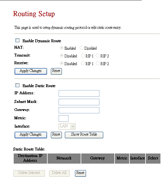
6.2 Routing
This page is used to setup dynamic routing protocol or
edit static route entry.
ChipSiP CWFC10x Serial
Enable Dynamic Route: Default is Unchecked,
Disabled. If enable dynamic route, than CWFC103 will
select the best routing route.
Apply Changes: Click on after option is selected
Enable Static Route: Default is Unchecked, Disable.
If a static route is known, than a static route can be
selected.

ChipSiP CWFC10x Serial
Chapter 8 System Maintenances
This chapter is to show how to maintenance
CWFC103.
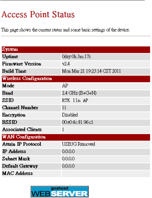
8.1 Status
This page shows the status and basic settings of the
CWFC103.
ChipSiP CWFC10x Serial
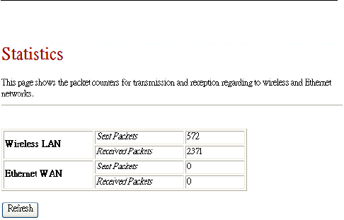
8.2 Statistics
This page shows the packet counters for transmission
and reception on the wireless and Ethernet networks.
ChipSiP CWFC10x Serial
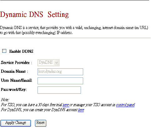
8.3 DDNS
DDNS, Dynamic DNS, is a service that provides a
valid, unchanging, internet domain name (an URL) to go
with that related IP address. It assign a fixed host and
domain name to a dynamic Internet IP address, which is
used to monitor hosting website, FTP server.
ChipSiP CWFC10x Serial
Enable DDNS: Default is Unchecked, Disable.
Service Provider: Select from the drop-down
menu.
Domain Name: It is an optional
User Name/Email: Enter user registration name
Password/Key: Enter user registration password
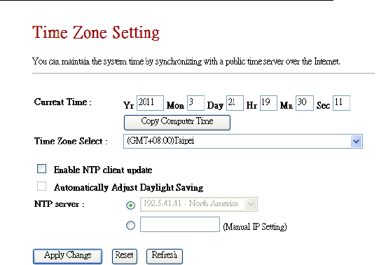
8.4 Time Zone Setting
The system time can be synchronized with a public
time server over the Internet.
ChipSiP CWFC10x Serial
Copy Computer Time: Get the time and date from the
connected system
Enable NTP client update: Default is unchecked,
Disable. If enable, than CWFC103 will synchronize the
time from the Internet time server.
Automatically Adjust Daylight Saving: Default is
unchecked, Disable.
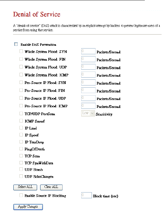
8.5 DoS
A DoS (Denial Of Service) attack is characterized by
an explicit attempt by hackers to prevent legitimate users of
a service from using that service.
ChipSiP CWFC10x Serial
Enable DoS Prevention: Default is UnChecked,
Disable
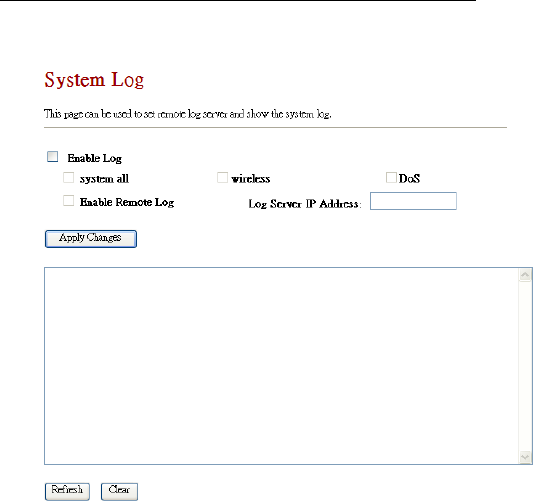
8.6 System Log
This feature can be set to remote log into server and
ChipSiP CWFC10x Serial
show system log.
Enable Log: Default is Unchecked, Disable.
Select the options to show on the log.
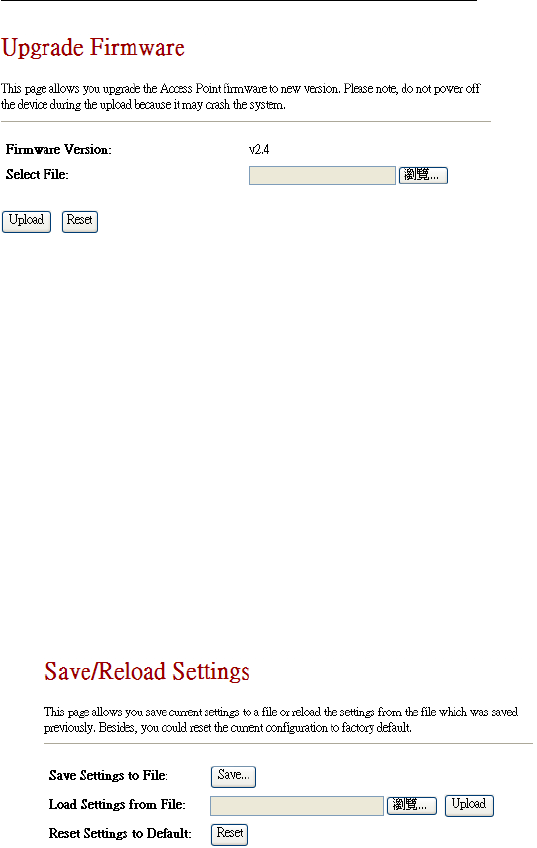
8.6 Upgrade Firmware
The feature allows CWFC103 firmware to be
upgraded to a new version.
NOTE: DON’T TURN OFF THE POWER DURING THE
UPLOAD FIRMWARE. FAILURE TO DO WILL
DAMAGE THE CWFC103.
ChipSiP CWFC10x Serial
It shows the current Firmware version.
Select the firmware file from the local system and
select Upload.
NOTE: DON’T TURN OFF THE POWER DURING
THE UPLOAD FIRMWARE. FAILURE TO DO WILL
DAMAGE THE CWFC103.
After it successful load the new firmware, select Reset
to reset the device to activate the new firmware
8.7 Save/Reload Settings
This feature allows the current settings to be saved to a
file and/or reload the settings from the file.
ChipSiP CWFC10x Serial
Save Settings to File: Save the current setting to a file.
Load Settings from file: Load the settings filefrom the
local computer/notebook. Select Upload to apply the
new setting from the file.
Reset Settings to Default: Reset to the setting to
original manufacturing setting.
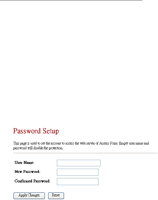
8.8 Password
This feature allows user to change or set a new
password of the account to access CWFC103. Empty user
name and password will disable the protection.
The manufacture default is “admin” and “admin” for
User Name nor Password.
It is highly recommended to setup the username and
password.

ChipSiP CWFC10x Serial
FCC Statement:
Federal Communication Commission Interference
Statement
This equipment has been tested and found to comply with
the limits for a Class B digital device, pursuant to Part 15 of
the FCC Rules. These limits are designed to provide
reasonable protection against harmful interference in a
residential installation. This equipment generates, uses and
can radiate radio frequency energy and, if not installed and
used in accordance with the instructions, may cause harmful
interference to radio communications. However, there is no
guarantee that interference will not occur in a particular
installation. If this equipment does cause harmful
interference to radio or television reception, which can be
determined by turning the equipment off and on, the user is
encouraged to try to correct the interference by one of the
following measures:
● Reorient or relocate the receiving antenna.
● Increase the separation between the equipment and
receiver.
● Connect the equipment into an outlet on a circuit
different from that to which the receiver is connected.
● Consult the dealer or an experienced radio/TV
technician for help.

ChipSiP CWFC10x Serial
FCC Caution: Any changes or modifications not expressly
approved by the party
responsible for compliance could void the user’s authority
to operate this equipment.
This device complies with Part 15 of the FCC Rules.
Operation is subject to the following two conditions: (1)
This device may not cause harmful interference, and (2) this
device must accept any interference received, including
interference that may cause undesired operation.
For product available in the USA/Canada market, only
channel 1~11 can be operated. Selection of other channels is
not possible.
This device and its antenna(s) must not be co-located or
operation in conjunction with any other antenna or
transmitter.
IMPORTANT NOTE:
FCC Radiation Exposure Statement:
This equipment complies with FCC radiation exposure
limits set forth for an uncontrolled environment. This
equipment should be installed and operated with minimum
distance 20cm between the radiator & your body.