ChronoTrack Systems CON-M200-USA1 Mobile RFID 4 Port Data Collection Device User Manual 1
ChronoTrack Systems LLC Mobile RFID 4 Port Data Collection Device Users Manual 1
UserManual.wiki
>
ChronoTrack Systems
>
CON-M200-USA1 User Manual
>
Users Manual 1
Contents
1.
Users Manual 1
2.
Users Manual 2
3.
Users Manual 3
Users Manual 1
Navigation menu
Upload a User Manual
Namespaces
Wiki Guide
HTML
PDF
Info
Views
User Manual
Discussion / Help
Navigation
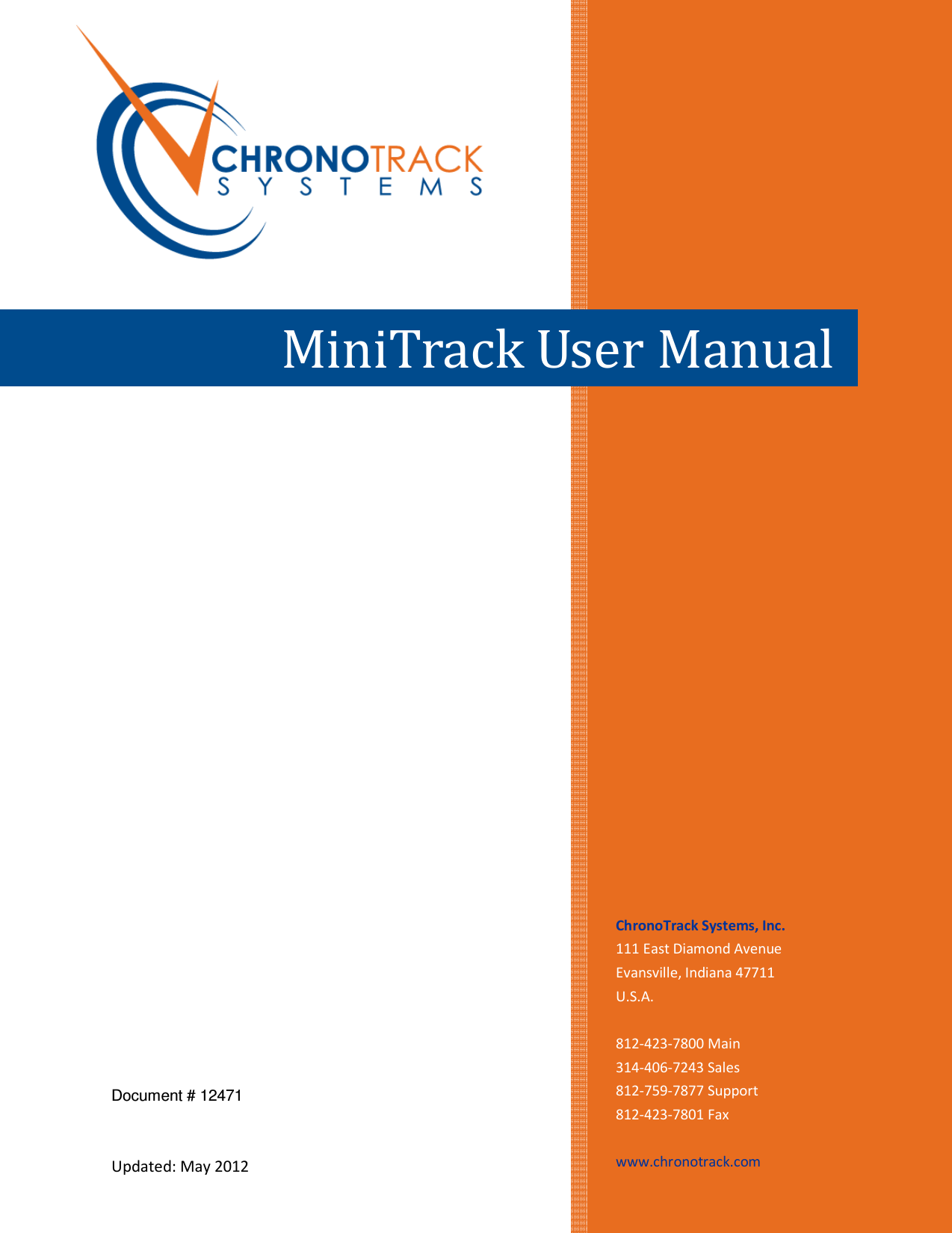
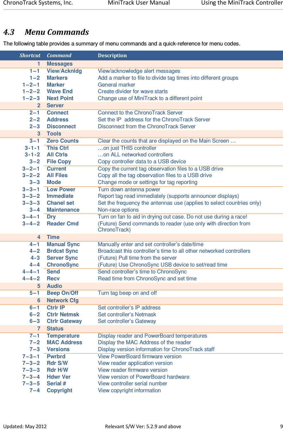
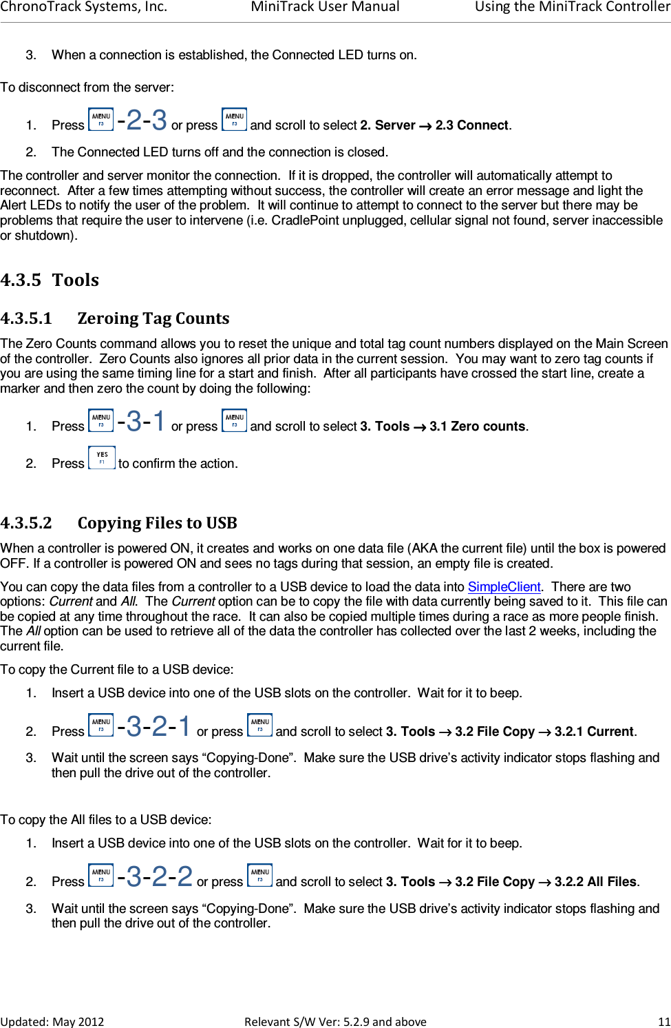
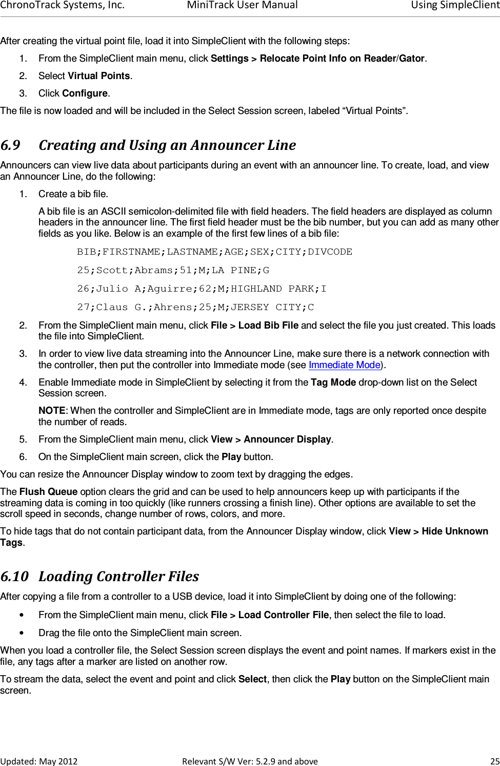
![ChronoTrack Systems, Inc. MiniTrack User Manual Using the MiniTrack Controller Updated: May 2012 Relevant S/W Ver: 5.2.9 and above 13 4.3.7.1 Sending Reader Commands The Reader Cmd menu item enables you to send commands directly to the reader. Use only with direction from ChronoTrack staff. Do not attempt to use this feature without advanced knowledge of these commands. If controllers are networked, these commands are sent to all controllers and subsequent readers on the network. To send a command to the reader: 1. Press -3-4-2 or press and scroll to 3. Tools →→→→ 3.4 Maintenance →→→→ 3.4.2 Reader Cmd). 2. In the menu, select the command to send. 3. Press Enter. 4.3.8 Setting the Time and Date The Time menu gives you the option to manually set the time and date on a single controller, synchronize the controller’s time to the server, or use the ChronoSync USB device to set or read the time. 4.3.8.1 Setting the Date and Time on a Controller To manually set the date and time on a controller and any others networked to it: 1. Press -4-1 or press and scroll to select 4. Time →→→→ 4.1 Manual Sync. 2. Use the numeric keypad to enter the date in [yyyy]/[mm]/[dd]. The controller inserts slashes automatically. 3. Press Enter to confirm the date or start typing a new date to change it. 4. When prompted, enter the correct time in [hh]:[mm]:[ss] format. The controller inserts the colons automatically. 5. Press Enter to accept the time. 6. Press to confirm message. The alert indicator LEDs light up to indicate the time has been set. 4.3.8.2 Broadcast Sync To push this controller’s time to all other controllers on the same network: 1. Press -4-2 or press and scroll to select 4. Time →→→→ 4.2 Brdcst Sync. 2. All controllers on the network will receive the new time. The alert indicator LEDs light up to indicate the time has been set. 4.3.8.3 Server Sync To synchronize the time with the server, you must first establish a connection with the server. To synchronize the time with the server: 1. Press -4-3 or press and scroll to select 4. Time →→→→ 4.3 Server Sync. 2. Press Enter to synchronize the time.](https://usermanual.wiki/ChronoTrack-Systems/CON-M200-USA1.Users-Manual-1/User-Guide-1750397-Page-17.png)
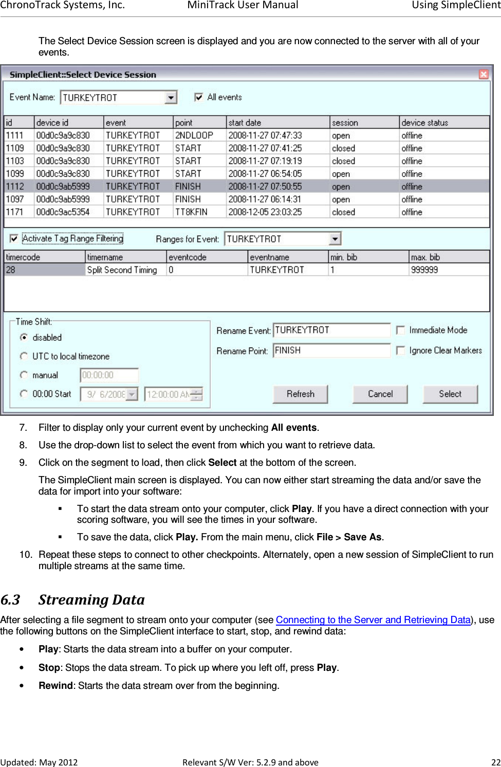
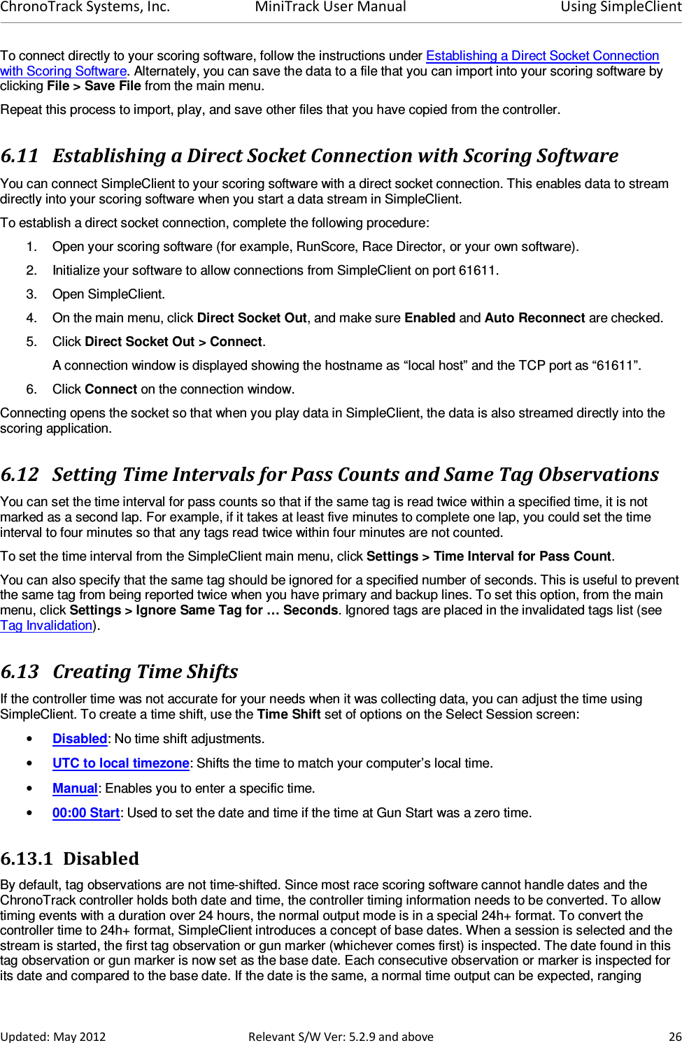
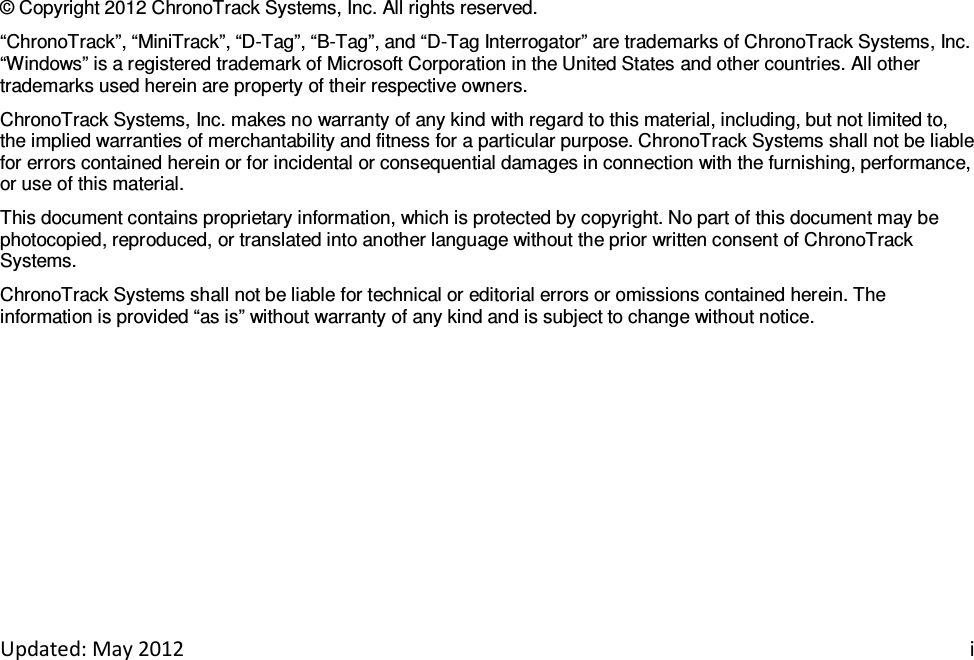
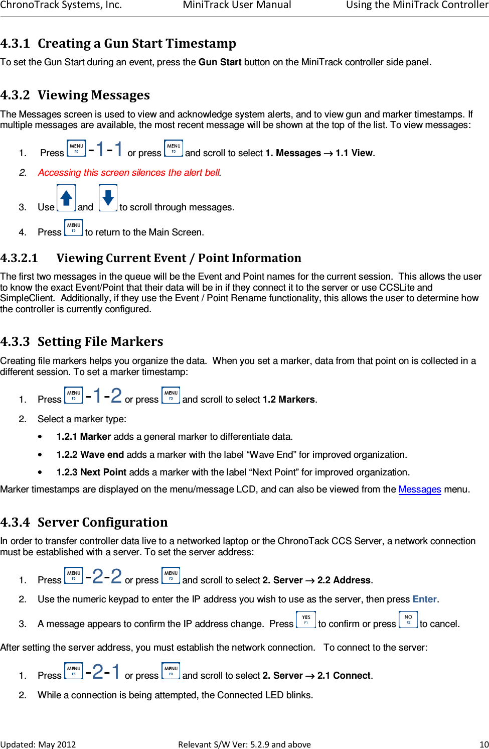
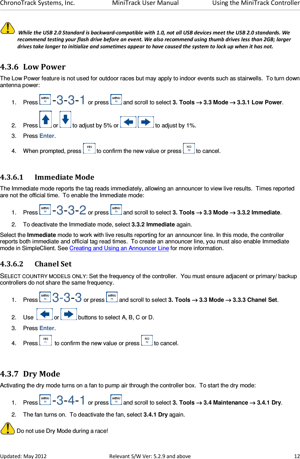
![ChronoTrack Systems, Inc. MiniTrack User Manual Using SimpleClient Updated: May 2012 Relevant S/W Ver: 5.2.9 and above 24 6.7 Filtering Data Filters can be applied to organize your data. You can filter out bib numbers from previous events or filter by various segments such as leagues. Tag filters can be created online and applied in SimpleClient so that only tag data within specified bib ranges, event codes, and/or timer codes is streamed. The Select Session File screen in SimpleClient is used to activate tag range filters that you create online. To filter the data shown in SimpleClient, complete the following procedure: 1. On the Select Session screen, select the point containing the data you want to filter. 2. Select the Activate Tag Range Filtering option. 3. The Tag Ranges for Event drop-down menu contains a list of tag ranges that you have created pre-event. Select the tag ranges for your event. 4. The columns in the middle of the screen display the filtering selections of timer and event codes and names, and minimum and maximum bib numbers. D-Tags are assigned a timer and event code when they are printed and encoded. 6.7.1 Creating Tag Ranges for an Event To create tag ranges for an event, complete the following procedure: 1. Prior to the event, log in to the ChronoTrack StreamManager at https://secure.chronotrack.com with your valid ChronoTrack user account. After logging in, a Welcome page with your name is displayed. 2. Click the Manage Events heading. 3. Click Add an Event. 4. Enter the information about your event. 5. Click Submit. The page now shows the tag range you created. 6. To save the tag ranges locally to your computer, from the main menu, click CCS Server > Update Local TagRange DB. 6.8 Creating Virtual Points Some events, like triathlons, will utilize multiple points at the same location (run in, bike out). For these types of events, it is possible either to use multiple controllers in normal mode, or to split up the points based on individual Gators or combinations of Gators from a single controller. To split the point names, you will need to relocate point information on your readers and Gators by creating and loading a virtual point file in Simple Client. This file specifies which MAC addresses should be assigned to which reader and ports. The virtual point file must be an ASCII file with an RMG file extension. The text must be semicolon-delimited with each new point on a separate row. The syntax for each row is: [ReaderMACAddress];[FirstGatorID];[LastGatorID];[NameOfNewPoint] Valid Gator IDs are 1, 2, 4, and 8. Below is an example of a virtual point file: 003487;1;1;GATOR1 003487;2;2;GATOR2 003487;4;4;GATOR3 003487;8;8;GATOR4 This example relocates each Gator to a new point name. The most common setup would be to separate both readers and can be done like this: 003487;1;8;READER1 0034AF;1;8;READER2](https://usermanual.wiki/ChronoTrack-Systems/CON-M200-USA1.Users-Manual-1/User-Guide-1750397-Page-28.png)