Cicor Deutschland 02MONILOG MONI LOG MicroShockDetector User Manual 15 MSD UserMan
SMT&Hybrid; GmbH MONI LOG MicroShockDetector 15 MSD UserMan
15_MSD_UserMan
MicroShockDetector
Edition 01/2016
INSTRUCTION MANUAL
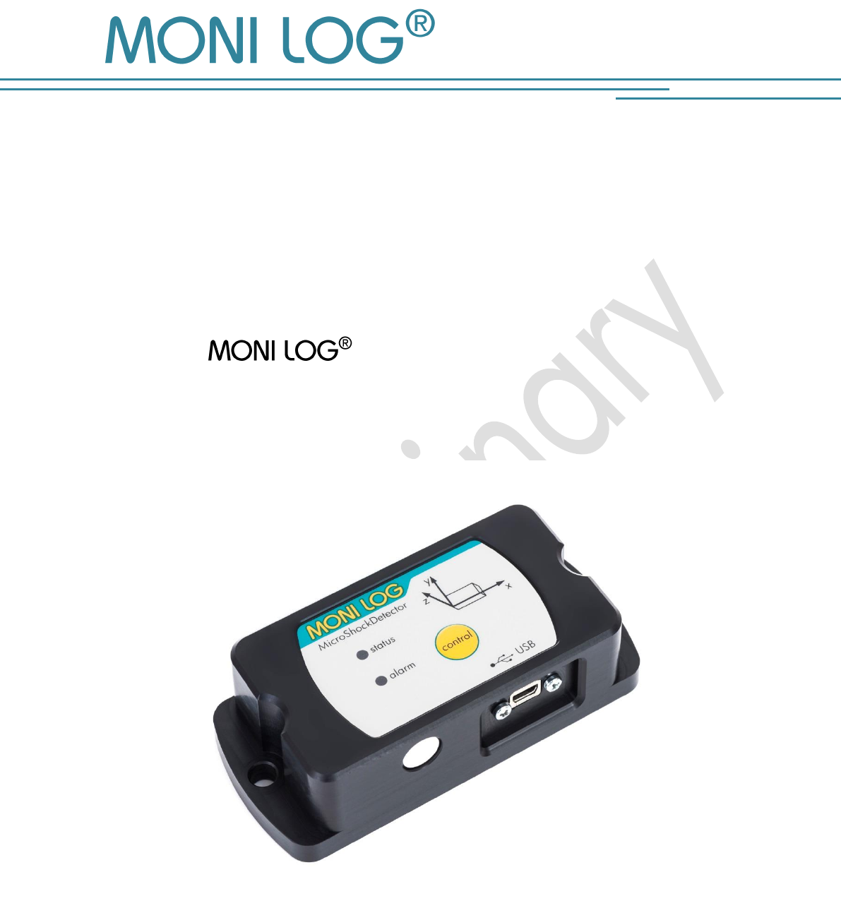
MicroShockDetector
(Transport data logger)

MicroShockDetector
- 1 -
P R OD U CT C ERTI F ICATION
still in progress

MicroShockDetector
- 2 -
T A B L E OF CONTENTS
PRODUCT CERTIFICATION .................................................................................. 1
TABLE OF CONTENTS ........................................................................................ 2
1. INTRODUCTION ...................................................................................... 4
1.1 SCOPE OF DELIVERY .................................................................................................... 4
1.2 FUNCTIONALITY ....................................................................................................... 5
1.3 ENVIRONMENTAL AND SAFETY INSTRUCTIONS ...................................................... 6
2. TECHNICAL DATA .................................................................................... 7
3. DEVICE DESCRIPTION .............................................................................. 8
3.1 DEVICE STRUCTURE / DEVICE VIEW ................................................................................. 8
3.2 OPERATION OF THE MICROSHOCKDETECTOR ................................................................... 8
3.3 OPERATION TIME AND BATTERY CHANGE ...................................................................... 11
3.4 MOUNTING INFORMATION ........................................................................................ 12
4. PC- S O F T W A R E – ANA L Y Z E R .................................. 13
4.1 INSTALLATION ......................................................................................................... 13
4.1.1 General software installation ....................................................................................... 13
4.1.2 USB driver ................................................................................................................ 13
4.2 GENERAL USE OF PC SOFTWARE .......................................................................... 14
4.2.1 Establishing a device connection .................................................................................. 14
4.2.2 File area ................................................................................................................... 15
4.2.3 Message window (log) ............................................................................................... 15
4.2.4 View of measurement data .......................................................................................... 15
4.3 MICROSHOCKDETECTOR .......................................................................... 17
4.3.1 Readout of status, configuration and measurement data .................................................. 17
4.3.2 measurement data, status, thresholds ............................................................................ 18
4.3.3 System events ............................................................................................................ 19
4.3.4 Acquisition periods .................................................................................................... 20
4.3.5 Synchronous data ...................................................................................................... 20
4.3.6 Alarm event table ....................................................................................................... 21
4.3.7 Shock events and shock curves .................................................................................... 21
4.3.8 Configuration of the MicroShockDetector ...................................................................... 25

MicroShockDetector
- 3 -
5. FIRMWARE-UPDATE ............................................................................... 28
5.1 PREPARATION .......................................................................................................... 28
5.2 CARRYING OUT UPDATE ............................................................................................. 29
6. DECLARATION OF CONFORMITY ............................................................ 30
WARRANTY CERTIFICATE ................................................................................. 31
MicroShockDetector
- 4 -
1. I N TRODUCTION
1.1 S C O P E O F D E L I V E R Y
Thank you
for having chosen the MicroShockDetector.
Scope of delivery1 (standard):
MicroShockDetector, incl. 1 R6 (AA, Mignon) exchangeable lithium battery
3.6 V / 2500 mAh,
Installation CD
Configuration software “ Analyzer“ with integrated software help
Driver for USB interface
Operating instruction in electronic form (PDF)
Application examples, guide for transport monitoring
Hard copy of the operating instruction, language according to the order
USB 2.0 interface cable (type A ↔ type Mini AB)
In order to be able to further optimise our products for the respective applications, we are always
open to suggestions and change requests on your part.
1) The scope of delivery can deviate from the standard due to special contract agreements!
MicroShockDetector
- 5 -
1.2 F U N C T I O N A L I T Y
MicroShockDetector is a small, universal and cost-effective data logger. Designed
for long-term measurement applications, it is ideally suited for the monitoring of transport goods
and critical environments. The integrated sensor system for the detection of shock events and for
temperature measurement enables different measuring applications. Configurable alarm
thresholds provide reliable detection of limit value exceedances. Shock loads are recorded and
assessed in real time, the temperature is recorded in an adjustable interval.
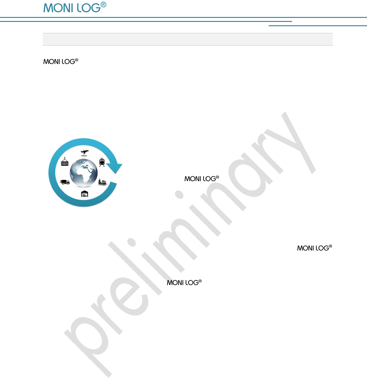
The compact and mains-independent design allows an
easy fastening on or in the transport goods or transport devices
with screws, magnetic bases or glue pads.
The housing of the device protects against dust and water
(Protection level IP 67) and is therefore also suitable for
outdoor use. The MicroShockDetector can thus be used
as a universal product companion in the international goods traffic
in storage spaces, in transit points and on the rails, also in the
water and air traffic.
The power supply is realized by a standard, replaceable lithium battery. Due to the very low
power consumption and the very long maintenance-free operation time the
MicroShockDetector is ideally suited for autonomous long-term applications. Energy-optimized
operational settings allow an autonomous running time period of typically 2 years.
The royalty-free configuration program Analyzer allows an easy and intuitive
configuration of the device. It offers a comprehensive adjustment of the device functions to your
application-specific requirements. In addition to the detailed analysis of the device data in
measurement tables and graphs, the program also provides export functions in external
applications (for example Microsoft Excel). Communication takes place via a USB interface.
By the report function an overview of the measurement data, including classification of all shocks
in acceleration classes and activities of the device will be created immediately without necessary
settings.
MicroShockDetector
- 6 -
1.3 E N V I R O N M E N T A L A N D S A F E T Y I N S T R U C T I O N S
Environment & Disposal
The MicroShockDetector contains, except the internal battery, no corrosive or
environmentally damaging substances.
Used batteries must be immediately removed from the device and afterwards disposed of in an
environmentally friendly manner, according to the applicable legislation. Lithium batteries are
hazardous waste.
Battery operation
The power supply in the MicroShockDetector is realized by a replaceable lithium
battery (Typ AA|LR6) 3.6 V 2500 mAh. The battery is not considered as dangerous good and
can be purchased in the specialist stores or by the equipment supplier.
Operation is not possible with 1.5 V batteries.
ATTENTION!
Use only intrinsically safe batteries.
In case of non-compliance with the national regulations/laws applicable in the handling of
lithium batteries, any liability and warranty claim becomes void!
Decommissioning
In case of decommissioning the devices must be properly switched off and all batteries must be
removed from the cases.

MicroShockDetector
- 7 -
2. TE C H N I C A L DA T A
Shock values
200 shock events, thereof 10 greatest events with signal curve of
4 sec duration; resolution 2 ms;
valuation from the view point of 3d space vector size
Acceleration sensor
3D-MEMS measuring range ± 8 g ; 1 mg resolution; ± (2 %
range + 5 % value) at 13 Hz / 20 °C; ± (3 % range + 6 % value) at
13 Hz / -20 °C / +60 °C
filter cut-off frequency 25 Hz fixed
Shock classification
Classification of shocks by amplitude in classes, number of shocks is
not limited; >0.25; >0.5g; >1g; >1.5g; >2g; >3g; >4g; >5g
Temperature
Measurement
-40°C to +65°C ± 1°K (-40°F / 150°F);
100.000 measurement values
Indicators
2 LEDs, for Status and exceeding Alarm limit
controls
One pushbutton for control and switch on/off password protected
Connections
Mini USB 2.0
Operating conditions
-40°C to +65°C; -40°F to +150°F; up to 98% rel. humidity
Power supply
Standard replaceable Lithium battery, size LR06 (AA, Mignon);
3.6 V 2500 mAh (Saft LS14500 or comparable),
Typical runtime 24 months in the switch-on period
data retention
Retention of measured data independent of battery for at least 10
years
Dimensions
108mm x 48mm x 30mm (LxWxH)
146mm x 50mm x 40mm (LxWxH mounted on magnetic feet)
Case material, weight
plastic housing with stainless steel plate on bottom,
mass circa 180g standalone, (380g total with magnetic feet)
Protection
IP67
Calibration
Manufacturer’s calibration valid for 2 years
Configurable
parameters
X,Y,Z recording threshold, X,Y,Z alarm threshold, minimum shock
duration, temperature measurement interval, Start-Stop-time (runtime),
password protection, via free Windows software
Data evaluation
Also with the Windows software displayable:
Measurement tables, curve graphics, active periods of the device,
export functions, reports, statistical analysis, battery monitoring
Software update
The device updates are provided by the manufacturer for the
Windows software and for the firmware
MicroShockDetector
- 8 -
3. DE V I C E D E S C R I P T I ON
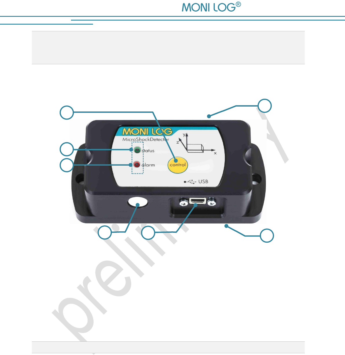
3.1 D E V I C E S T R U C T U R E / D E V I C E V I E W
1 On/off/control key
5 Name plate incl. serial number
2 Status LED green/red
6 USB port with cap
3 Alarm LED red
7 Battery cover
4 Temperature sensor
3.2 O P E R A T I O N O F T H E M I C R O S H O C K D E T E C T O R
For the operation of the device there is a control key which function is depending on the current
status and the duration of the key press. The current status is indicated with 2 LEDs.
7
4
1
6
2
3
5

MicroShockDetector
- 9 -
Checking the device on-state
To determine whether the device is switched on or off, press briefly the control key (<2 s):
status LED does not light up the device is OFF
status LED lights up briefly the device is ON
Switching on device
For switching on device, press briefly the control key for at least 2 seconds until the status LED
lights up. Then release the key. If the device is equipped with an on/off code, then it can only
be activated via the software. This is indicated by the lightening status LED at least for 20 sec. If
the software activation is not performed the device switches off again after 20 seconds. To
activate the device, connect it during the lightening of the LED to a PC and start the
Analyzer. During the reading out the device it will be detected that the device is protected with
password. At this point you should enter the device password. Follow the instructions of the
software to activate the device. Explanations on the configuration of the on/off code you can find
in Chapter 4.3.8 in the section „ Password configuration".
If no code is necessary, the device begins data recording immediately.
Switching off device
To switch off the MicroShockDetector, press briefly the control key for at least 2 sec. until the LED
alarm lights up red. If the key is still pressed, the status LED lights up red for 1 sec. Now they can
be released. The device switches off. This can be checked by short pressing the key. If you
release the key during the lightening, the device will be still switched on.
If the device is equipped with an on/off code, then it can only be deactivated via the software.
To signal this, the LED status starts rapid lightening red. To switch off the device, connect it to a
PC and start the Analyzer. During the reading out the device it will be detected that it
is protected with password. At this point you should enter the device password. By the tab
"Configuration" and the key "Password configuration" you can switch off the device.
Explanations on the configuration of the on/off code you can find in Chapter 4.3.8 in the section
„Password configuration".

MicroShockDetector
- 10 -
Display the function state
Status
Device status
Condition
Secondary
condition
Successor
status device
LED status
green
LED status
red
LED alarm
red
A0
Device
on
Idle task
Operational readiness
A0
Off
Off
Don’t
care
A1
System error
A1
Off
Off
Don’t
care
A2
Critical battery status
A2
Off
Off
Don’t
care
A3
Exceedance of alarm
threshold
A3
Don’t
care
Don’t
care
Off
B1
Device
on
Pressing Key
Control
t < 2 s
Measurement activated
A0 possibly A3
1 s
off
Don’t
care
B2
Measurement
deactivated
A0 possibly A3
100ms of
all
200ms
off
Don’t
care
B3
Alarm event available
A3
Don’t
care
Don’t
care
1s
B4
System error
A1
off
1s
Don’t
care
Critical battery status
A2
off
1s
Don’t
care
B5
Pressing Key
Control
2 s ≤ t < 4 s
Without active
power-off protection by
password
Ax or B6
off
off
200ms
of all
400ms
B6
Pressing Key
Control
t ≥ 4 s
C0
off
1 s
off
B7
Pressing Key
Control
t ≥2s
With active
power-off protection by
password
Ax (power-off
protection by
password)
off
100ms
of all
200ms
off
C0
Device
off
C0
off
off
off
C1
Pressing Key
Control
t < 2 s
C0
off
off
off
C2
Pressing Key
Control
t ≥ 2 s
Battery empty
C0
off
off
off
C3
Without active
power-on protection by
password
Ax
2 s
off
off
C4
With active
power-on protection by
password
Ax after valid PW
entry on software
in 20s
C0 after 20s
without PW entry
0,5s of
all 1s
0,5s of
all 1s
off
D0
Device
on
Measurement data
recording
Ax
on
off
Off
MicroShockDetector
- 11 -
3.3 O P E R A T I O N T I M E A ND B A T T E R Y C H A N G E
Operation time
The device runtime of MicroShockDetector depends on the set measurement
parameters, the battery type and the use conditions. The number of shocks on the triggering
threshold of the device is mainly decisive. Assuming that the device is activated by the shock up to
a maximum of 100,000 times, the typical runtime of a battery is about 2 years. The actual
remaining battery charge is monitored by the device and displayed by the software.
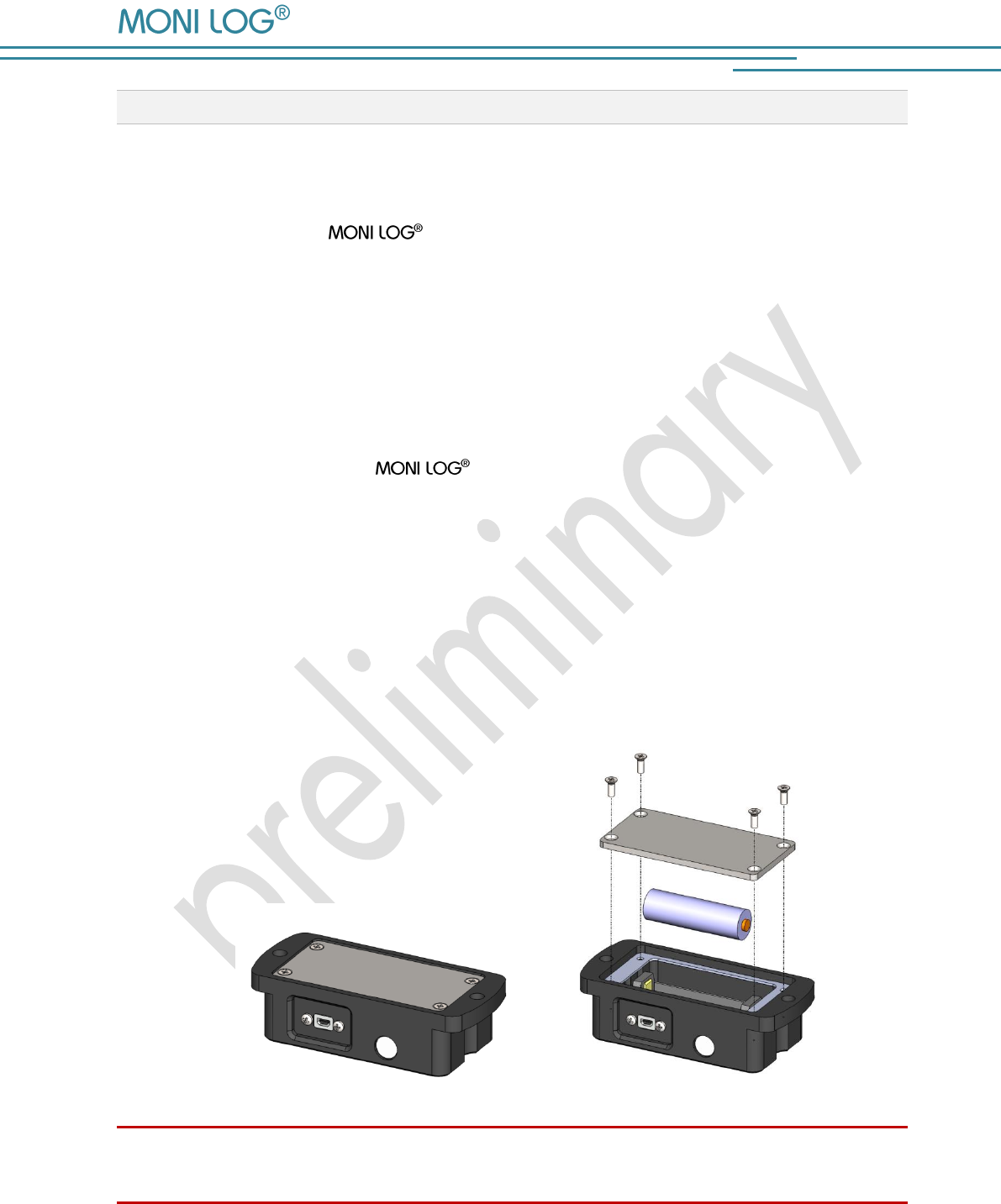
Battery change
Prior to a battery change the MicroShockDetector must be properly switched off,
otherwise the data loss of the device cannot be excluded.
For the change of the battery proceed as follows:
1) Remove the battery cover by loosening the fastening screws by means of a screw driver.
(Cross slot H size 1). Afterwards, you can pull out the battery out of the battery holder.
2) Now, insert the new battery according to the specified polarity into the device.
3) In a last step, screw again the battery cover onto the device. Pay attention to the maximum
tightening torque of 0.3 Nm and the correct position of the seal.
Attention:
Ensure the correct polarity when inserting the batteries!
MicroShockDetector
- 12 -
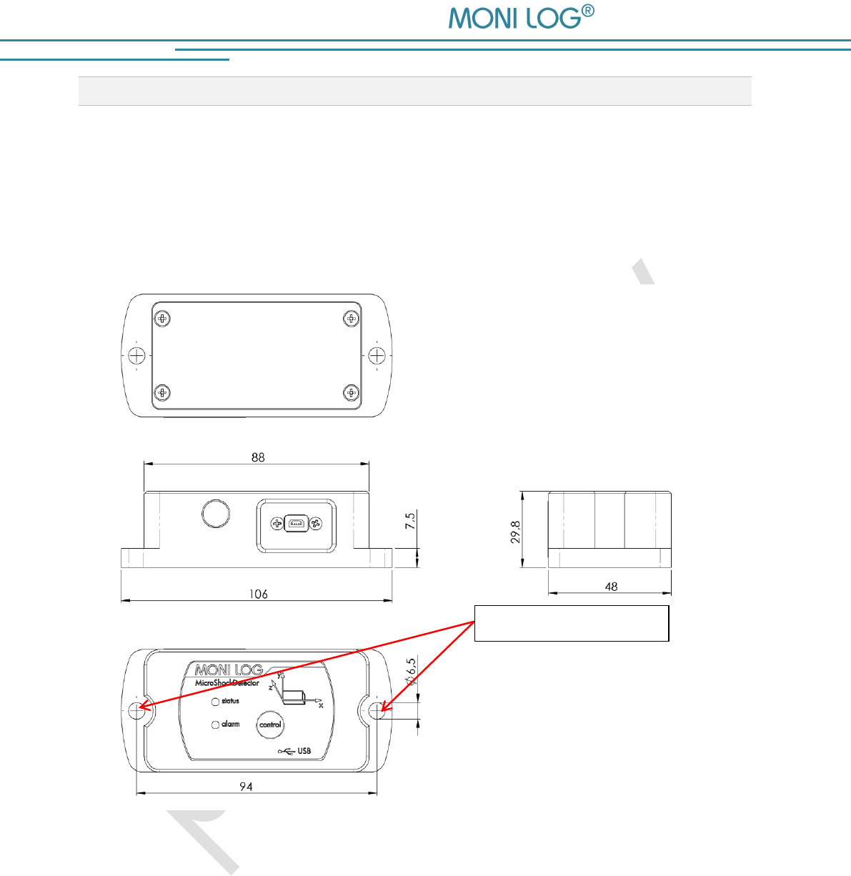
3.4 M O U N T I N G I N F O R M A T I O N
The device can be mounted on the transport material by 2 mounting screws (see Image 1),
according to the mounting halls. Optionally, the device can also be mounted using magnetic
bases on magnetic surfaces. The use of the glue pads is also possible if they do not have a shock-
absorbing foam coating.
Image 1: Dimensions and mounting information of the MicroShockDetector (dimensions in mm)
Mounting holes
MicroShockDetector
- 13 -
4. PC-S O FT W A R E – A N A L Y Z E R
The evaluation programme Analyzer can be used both for the readout and
configuration of the MicroShockDetector and other devices. It is intended
for the display and analysis of the recorded data in tabular/graphic form. Furthermore, data sets
can be saved locally on your PC or loaded from your PC.
4.1 I N S T A L L A T I O N
4 . 1 . 1 G e n e r a l s o f t w a r e i n s t a l l a t i o n
The included CD contains the software installation Analyzer, the driver for the USB
interface and documentation. Please start the installation by double clicking on the file
"setup.exe" and follow the instructions.
Note:
To install the software and the USB driver you need administrator rights on the PC
4 . 1 . 2 U S B d r i v er
If the MicroShockDetector is connected for the first time it may be necessary to install
a USB driver on the PC. The "FTDI CDM Driver" is included on the installation CD and is set with
the software installation if it is not already present on the PC.
Now connect the MicroShockDetector by means of the included USB cable with your
PC. While the device connects to the PC the status LED lights up green. After the LED has gone
off, the USB is ready and you can read data from the device with the Analyzer.
MicroShockDetector
- 14 -
4.2 G E N E R A L U S E O F P C S O F T W A R E
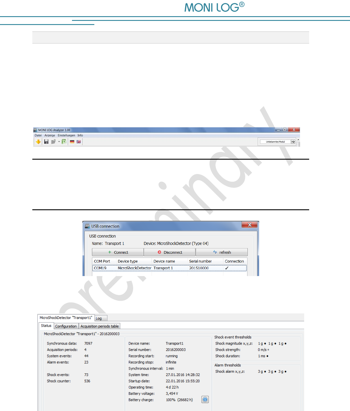
4 . 2 . 1 E s t a b l i s h i n g a d e v i c e c o n n e c t i o n
If the device driver is installed, the connection, as a rule, will be automatically established upon
the start of the evaluation software, if a device is connected via USB.
If the evaluation software has been active before plugging of the device or you want to connect
a device to a different COM port, select the device via the USB menu at the top right.
In case of connection problems:
If the USB connection is not initiated correctly select the
Refresh button (blue double arrow), disconnect the USB cable from the device
and reconnect it.
Image 2: USB connection window, connection established to COM19
After a successful USB connection, the status data of the connected device are displayed:
Image 3: Status view
MicroShockDetector
- 15 -
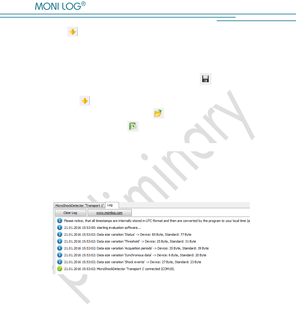
By the icon or menu „File / Download measuring data“ you can load the additional
measurement data, as described in Section 4.3.1.
4 . 2 . 2 F i l e a r e a
The data read out by the device from the USB can be saved by icon or menu „Save file” on
a data carrier. Please observe that the measurement data are included in the file only if it has
been read out by . In the other case only the status data are included. The saved data can
also be loaded in the PC programme. The button „Open file “opens the dialog for choosing
a file. One click on the button with the Excel icon exports the read out data in an Excel file.
4 . 2 . 3 M e s s a g e w i n d o w ( l o g )
The message window, which can be found as a programme tab “Log”, renders possible an
overview on the actions performed by means of the programme or the status changes of the
device during the established USB connection. Error messages and notes, e.g., for performance
of configuration commands, connection setup to devices, saving of data, etc. are listed here.
Image 4: Log window
4 . 2 . 4 V i e w o f m e a s u r e m e n t d a t a
The measurement data should first be read out as described above, either from a connected
device or exist in an open file. The representation is possible in each case as a graph or table.
MicroShockDetector
- 16 -
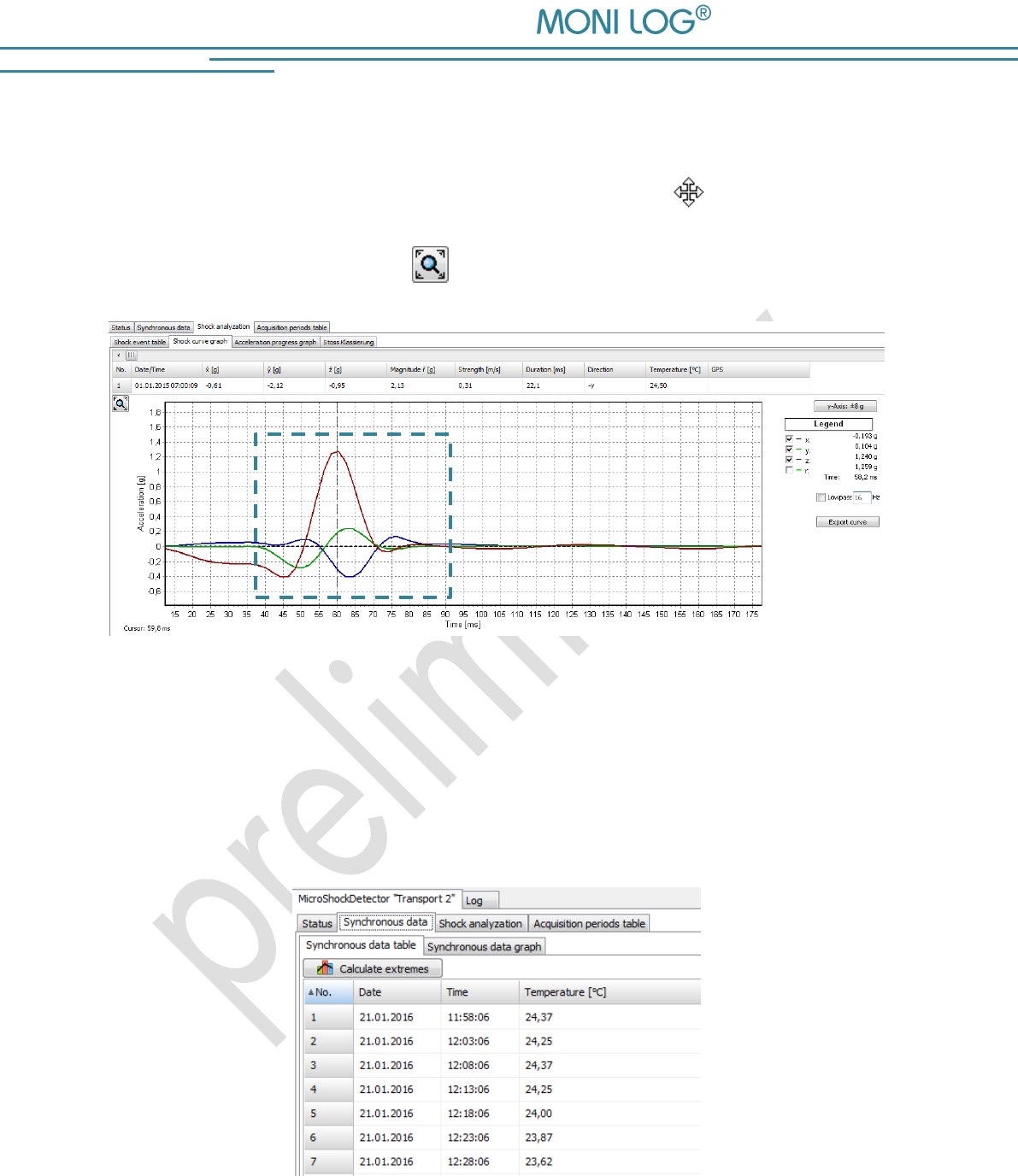
Graphs
In a graph it is possible to zoom in. For this, draw up a selection window using the mouse (see
Image 5). The view can be shifted using the held right mouse button . By moving the mouse
wheel up/down concentric zooming is carried out. The standard zoom is restored by a double
click on the graph or using the button .
Image 5: Zoom selection window
Sorting function in tables
For tables a sorting function is available. This is carried out by clicking on the respective column
in the table header. This facilitates the finding of maximum/minimum values. The sorting is made
alternately in ascending and descending order. The data sets remain unchanged by this.
Image 6: Sorting table columns
MicroShockDetector
- 17 -
4.3 M I C R O S H O C K D E T E C T O R
4 . 3 . 1 R e a d o u t o f s t a t u s , c o n f i g u r a t i o n a n d
m e a s u r e m e n t d a t a
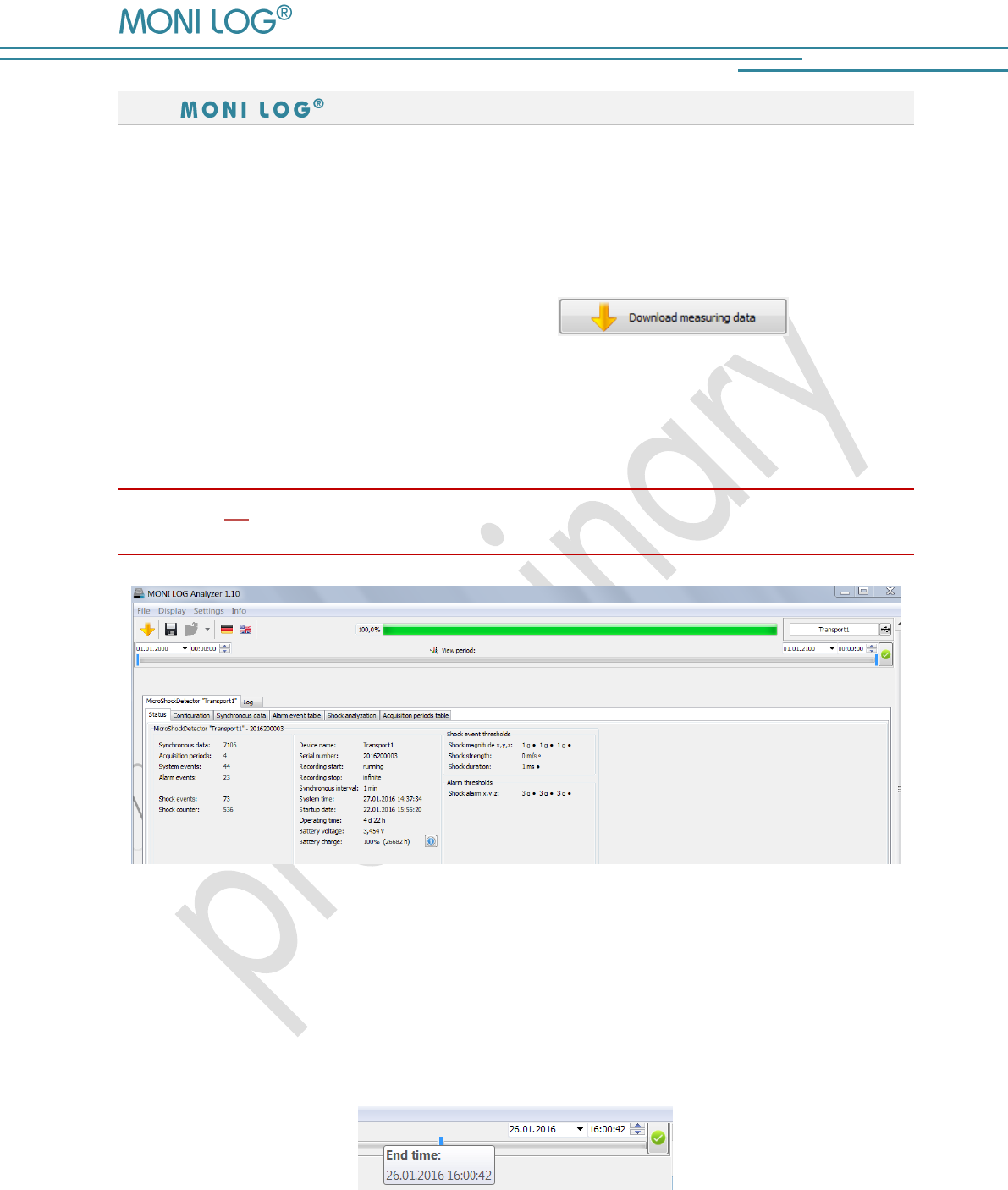
After connecting to the device status data, configuration and acquisition periods are automatically
read and displayed as described in Image 3. The measurement data, such as temperature data
or shock curves are manually requested by the button . This may take
a few seconds to several minutes, depending on the number of data records. A progress bar
shows the current selection status. According to the available measurements the associated
program managers and graphs are opening. A detailed description of the program areas can be
found in the following chapters.
Please do not disconnect the USB cable from your PC or MicroShockDetector as long as data
transmission takes place!
Image 7: Overview after reading the measurement data of a MicroShockDetector
The view period of data can be limited to the desired time range by the view period. This
simplifies data analysis and finding of certain events. Enter in the fields the desired start and end
date and confirm your entry using the Enter key on your keyboard or the green button on the
input field on the right. The view period can also be adjusted using the slide bar, where the blue
bars are moved by the mouse (see Image 8).
Image 8: Slide bar for view period

MicroShockDetector
- 18 -
4 . 3 . 2 m e a s u r e m e n t d a t a , s t a t u s , t h r e s h o l d s
The paremeters, represented on the Image 7, have following meanings:
Measurement data (Column 1):
Synchronous data: number of the continuously stored data records of the
temperature measurument
Acquisition periods: number of the time periods, when the module was ready to
measure
System events: number of the external events (see Section 4.3.3)
Alarm events: number of the events when at least one alarm threshold was
exceeded
Shock events: number of the shock records, which have exceeded thresholds
Shock counter: total number of the shocks which have led to the activation of the
device
Status data (Column 2):
Device name: device name, selected by the user (freely selectable)
Serial number: serial number of the device (unchangeable)
Recording start: beginning of the measuring or running
Recording stop: end of the measuring or infinite
Synchronous interval: time interval for the time-synchronous (continuous) recording of the
temperature
System time: internal time of the device
Startup date: date of the first start up
Operating time: total running time of the device
Battery voltage: actual voltage of the battery
Battery charge: remaining battery charge, details will be shown by clicking on the
battery icon
Firmware version: actual firmware version of the device
Hardware version: actual hardware version of the device
MicroShockDetector
- 19 -
Shock event thresholds (Column 3):
Shock magnitude x,y,z: minimal amplitude of the acceleration (storage criterion);
is adjustable and activatable for each axis
Shock strength: minimal „Area under the curve of the resultant space vector“,
additionally adjustable storage criterion
Shock duration: minimal duration of an impact (storage criterion)
Shock alarm x,y,z: acceleration value, from which an alarm event is generated,
is adjustable and activatable for each axis
The threshold values, marked by a filled circle •, must be all reached at the same time to store a
shock event.
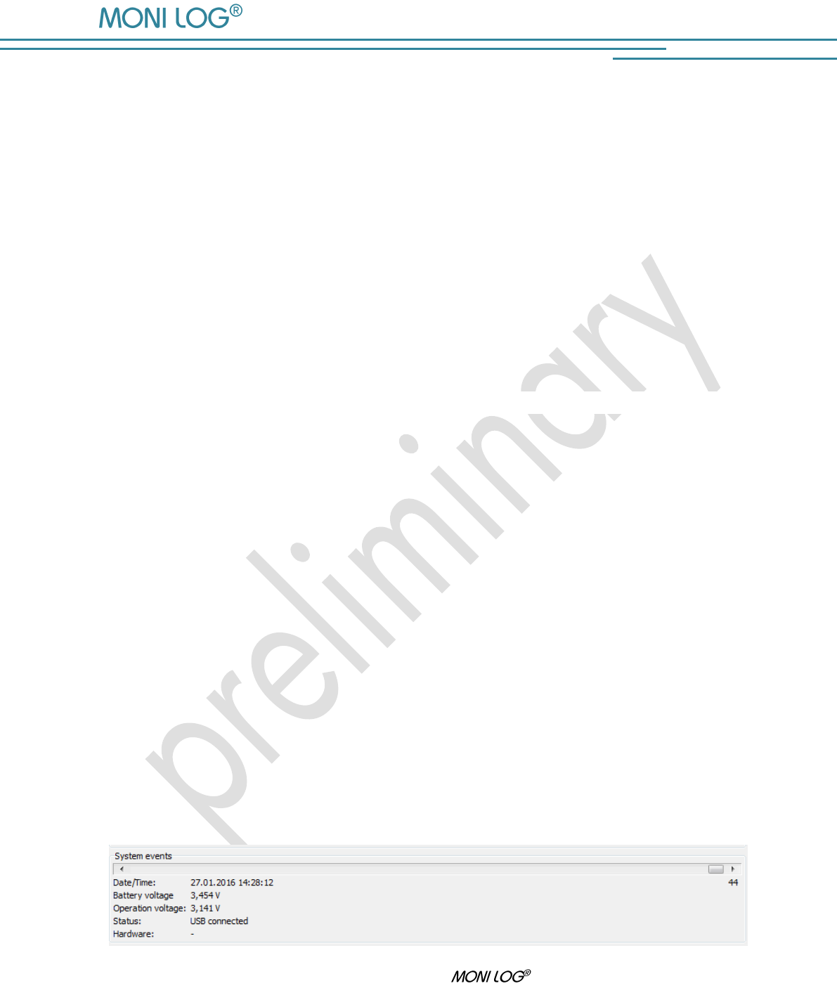
4 . 3 . 3 S y s t e m e v e n t s
The system events show events that concern the status and the operating behaviour of the sensor
module. Existing errors in the hardware are also recorded. The display field for system events is
normally hidden and can be displayed by activating the menu option “Settings - Advanced
diagnostics”.
The corresponding view opens in the lower image area. The events can be displaced by the bar.
The following system events can occur:
Start: The sensor module was switched on
Hour counter: 24 h of operating time of the sensor modules are expired
Device configured: The sensor module was configured.
Channels configured: Alarm events/Thresholds were activated/changed
Device switched off: The sensor module was switched off
Time synchronized: The system time of the device was configured
USB aktive: The event was generated by activities of the USB interface
Image 9: Display of system events of a MicroShockDetector
MicroShockDetector
- 20 -
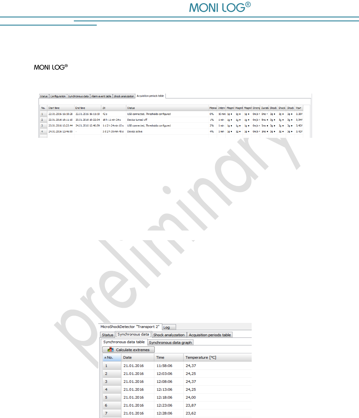
4 . 3 . 4 A c q u i s i t i o n p e r i o d s
The acquisition periods offer an overview of the individual configuration time segments of the
MicroShockDetector. This way it can be retraced how the sensor module was
configured at the respective period.
Image 10: Table of acquisition periods
The start and end time, the active time period and the reason which has led to the completion of
the acquisition period are shown. Furthermore, all set thresholds and event channels are
registered for the period. A new acquisition period begins, if the device was switched off or has
been configured.
4 . 3 . 5 S y n c h r o n o u s d a t a
Synchronous data are measurements, synchronously and continuously recorded at a fixed
interval. The records are continuously displayed in a table (see Image 11). In the program tab
"Synchronous data graph" the synchronous data are displayed graphically. The measurements of
the cursor position are displayed in the legend on the right side of the graph.
Table of the temperature measurements
Image 11: View of synchronous data table
MicroShockDetector
- 21 -
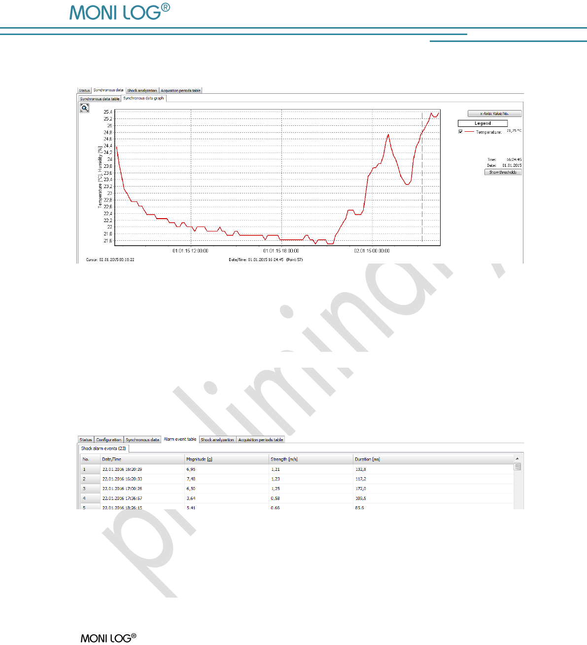
Graph of the temperature measurements
Image 12: View of synchronous data graph
4 . 3 . 6 A l a r m e v e n t t a b l e
Alarm events include all shocks have exceeded at least one of the alarm thresholds. (see Image
13).
Image 13: View of alarm events
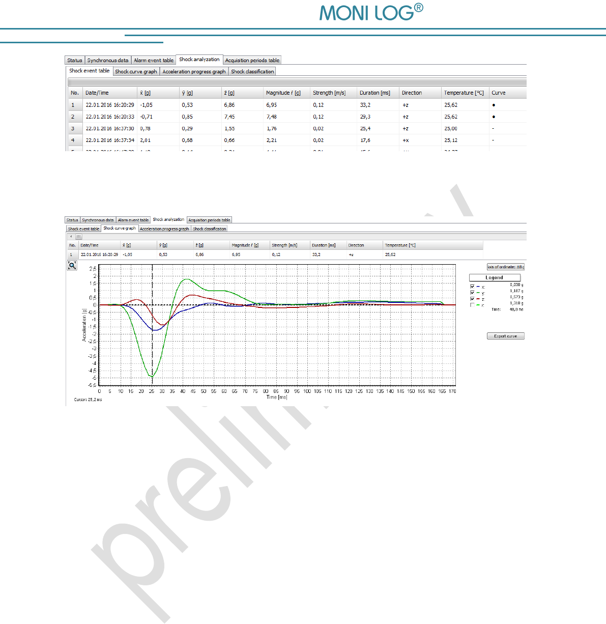
4 . 3 . 7 S h o c k e v e n t s a n d s h o c k c u r v e s
A MicroShockDetector registers 200 shock events by the set threshold values and the
10 largest shocks of it to the curve progression of over 4 seconds.
All shock events are tabular performed under the program tab „Shock event table“. The
corresponding curve can be invoked by double-click on the table row, if the circle symbol • is
available in the column "Curve".
MicroShockDetector
- 22 -
Image 14: Shock event table
Image 15: Shock curve graph
The shock curves can be browsed by the overlying scrollbars. By activating or deactivating the
"Hook" in the legend on the right side, the x,y, z-channel and the amount curve can be blended
out (see Image 15).
The vertical graph axis is switched between the maximum values of the curve and the full
measuring range of ± 8 g by the button „Axis of ordinate“.
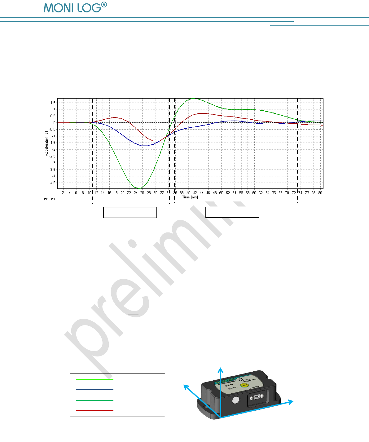
Principle of the shock recording:
The shock recording starts when the value of the acceleration exceeds the internal trigger
threshold of 0.25 g on at least one measurement channel (approximately 3% of the measuring
range).
The measuring points are continuously recorded with 500 Hz per channel, filtered on an upper
cut off frequency of 25 Hz and it selects separate shock impacts. A shock impact starts exceeding
the trigger threshold on at least one measurement channel and ends when the main thrust
(channel with the absolute maximum of shock) changes sign (zero crossing) or all 3 channels fall
MicroShockDetector
- 23 -
below the trigger threshold again. Within a period of 4 s more shock impacts can occur, for
example, by vibration. The impact with the largest amplitude is evaluated at the end of a curve
period and compared with the configured criteria. A shock curve is permanently stored if the
registration thresholds met on at least one measurement channel, shock strength and shock
duration for this shock impact.
Image 16: valuation of shock events
As a shock event is considered the largest single impact within the sampling time of 4 s, which
meets all the set conditions (amount of shock, shock strength, shock duration) (in this example
Image 16 Impact 1). In addition to the measurement of the 3 channels, a value for the space
vector and integrated value for the shock strength of this impact are calculated at each
measurement point. The shock strength is equivalent to the difference speed.
Space vector:
Shock strength:
y
z
x
Space vector
X axis
Y axis
Z axis
Image 17: MicroShockDetector main axes of acceleration
Impact 1
Impact 2
MicroShockDetector
- 24 -
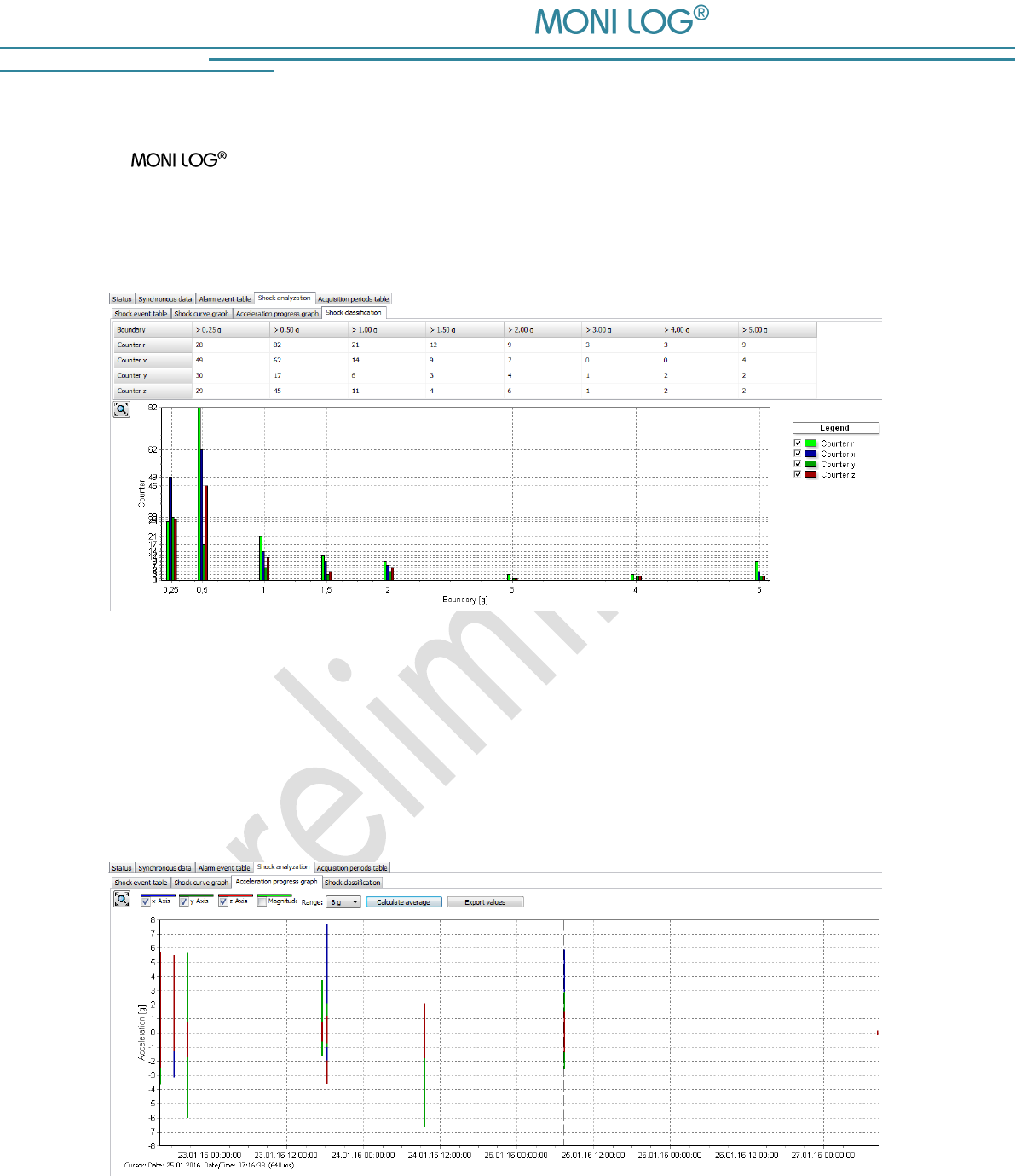
Shock classification
The MicroShockDetector evaluates the acceleration amplitude of all shocks separated
by the thrusts X, Y and Z and the resulting space vector R. All shocks are specified by the
amplitude in laid down threshold classes regardless of whether these are stored as shock events
or shock curve with timestamp and measurement. It is displayed as a table and graph (Image 18).
Image 18: Shock classification
Acceleration progress graph
Recorded shock events with their maximum acceleration amplitudes are shown in a line graph
(Image 19). It is possible to zoom into the curve shape in. By the button "Calculate average"
statistical values of acceleration are calculated on all shock events.
Image 19: Acceleration progress graph
MicroShockDetector
- 25 -
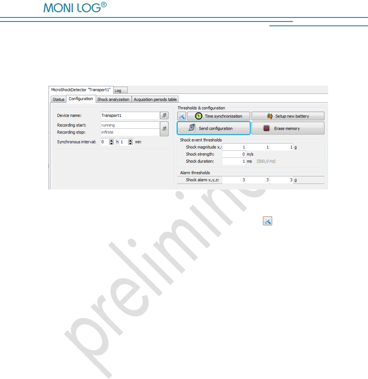
4 . 3 . 8 C o n f i g u r a t i o n o f t h e M i c r o S h o c k D e t e c t o r
The configuration section is only visible if a device is connected to USB, which you can configure.
When viewing records from files this window does not appear (Image 20).
Image 20: Configuration of the device
For the meaning of the used settings see also Section 4.3.2. By the icon you can restore the
default settings.
The buttons have the following functions:
Time synchronisation: synchronizes the clock in the device to PC time
Setup new battery: resets the battery consumption meter after the change of
the battery in the device
Send configuration: sends the all settings to the device
Erase memory: deletes the all data in the memory of the device
Password configuration: allows you to change the device password
Configuration of the registration thresholds
The correct configuration of the registration thresholds is fundamental for the storage of the shock
measurements. A shock must reach the shock amount, specified at least on one axis X, Y or Z and
at the same time the minimum shock length. When a value greater than 0 m/s is entered, the
shock strength must be also met as a criterion (see also Section 4.3.7 Principle of the shock
recording).
MicroShockDetector
- 26 -
Change of the synchronous interval and configuration of the alarm events:
The configuration of the synchronous interval is performed using the selection fields "Synchronous
interval" in hours and minutes (Image 20). During the configuration of the zero no record of the
time-synchronous temperature measurements takes place.
The entry fields for the limit values of the alarm events are next to it. On the basis of the
configured thresholds, alarm events are saved if exceeding the threshold is detected during the
measurement run.
Erase Memory:
The function „Erase Memory“ erases the all data, stored in the device.
Attention!
Ensure that you have completely read out the data and saved them
as *.msd file before erasing! Erased data cannot be restored!
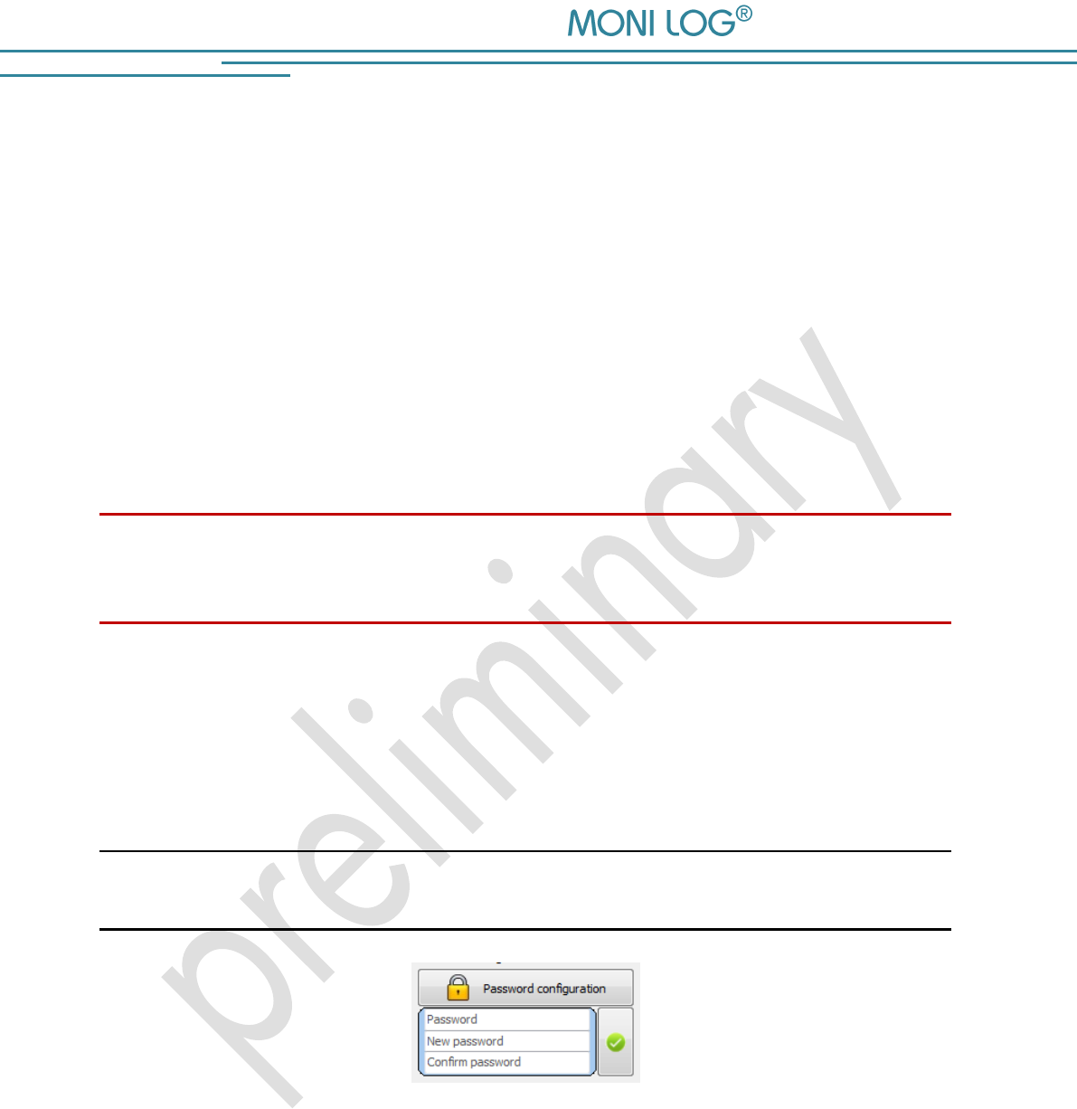
Password configuration:
It is possible to protect the device with a password. All accesses via USB are blocked by
password activity until the password is entered correctly. The password may contain up to 8
characters. By clicking on the green tick the new password is transmitted.
Note:
To remove a password again, leave the field "New password" empty.
Image 21: Creating/changing password
Password: Enter the current password
New password: Enter the desired new password
Confirm password: Please enter the new password for confirmation

MicroShockDetector
- 27 -
Change of the device name:
The device name of the MicroShockDetector can be changed by the user. The
maximum of up to 16 characters is available. The designation will be saved and transmitted to
the device by pressing the ENTER key on your keyboard or by clicking the button next to it on the
right. The designation can be selected individually. It makes sense to name the designation
according to measuring point, measurement task, etc. (for example, "Transport 1").
Adjust recording period:
The desired recording period for the device can also be set by the user. If a recording period is
defined, the measurement recording begins at the starting time. By exceeding the stop time point,
the measurement recording is stopped. If the entry fields are not empty, the measurement
recording runs as long as the device is switched on.
The entry of the starting and stop time proceed in local time in date format:
dd.mm.yyyy hh:mm:ss
(Day.Month.Year Hour:Minite:Second)
The configuration of the recording period is possible by pressing the ENTER key on your
keyboard or by clicking the button on the right.
Configuration of the device time:
The synchronization of the system time is done by clicking on the clock icon. The device works
internally with Coordinated Universal Time (UTC). This is the same all over the world, this means
independent from the time zones. The PC program shows, however, depending on the time zone
setting of your PC, the time, converted to your local system.
MicroShockDetector
- 28 -
5. FI R M W A R E - U P D A T E
5 . 1 P R E P A R A T I O N
Through a firmware update, a MicroShockDetector receives an updated application
program if this update file is provided by the manufacturer.
Prior to the firmware update the following points must be observed:
The activation of the update mode can only be carried out, if the
MicroShockDetector is switched off. If your device is still switched on, please switch it off.
Have ready the included mini USB cable and plug one end of the cable in a free USB port
of your computer for the preparation. Do not plug the USB cable into the MONI LOG®
device yet!
Ensure that on your computer no sensor network PC programmes are executed and all
necessary drivers are installed.
Attention!
Back up all measurement, diagnostics and configuration data of your device prior to the firmware
update to prevent a possible data loss. The memory is reset to default settings.
In the switched off condition of the device connect the USB cable and keep the control key
pressed (~1 second, status LED is illuminated green) until the status LED starts to flash red with
1 Hz. The update mode is active now. It only remains active as long as the USB cable is
connected. If the control key is released before the detection of the update mode, the device starts
the normal operating mode.
Proceed now with the instructions according to chapter 5.2 „Carrying out update“.
MicroShockDetector
- 29 -
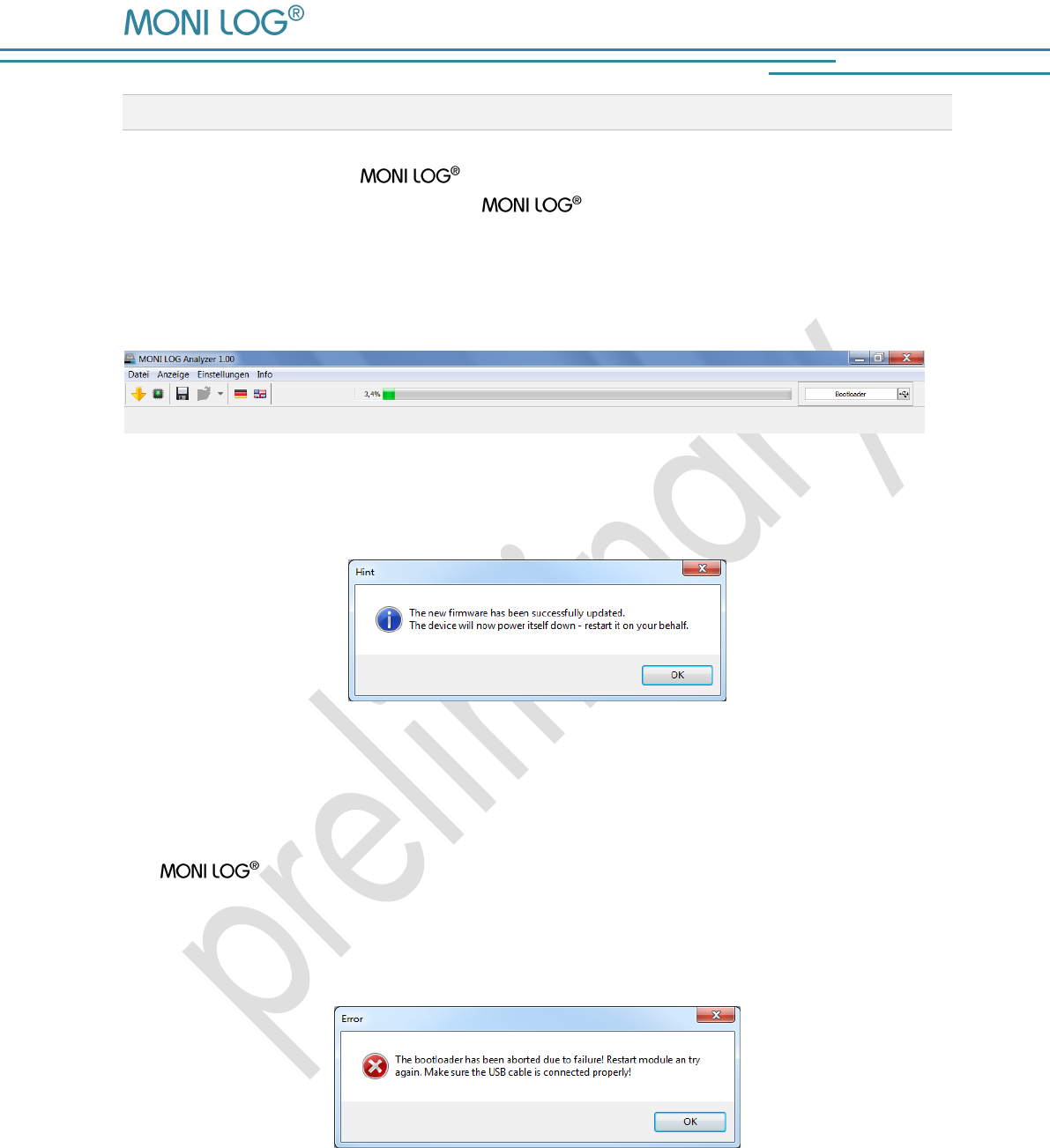
5 . 2 C A R R Y I N G O U T U P D A T E
After you have started your device in the update mode, start the PC software. The PC
software should automatically detect the device which is in the update mode and
open a window to select an „Encrypted Hex File“.
After selecting the update file the charging process, which must not be interrupted, starts. The
status LED illuminates red permanently.
Image 22: Firmware update
If the progress bar shows 100%, then the message of the successful completion of the update
appears.
Image 23: Information message after successful firmware update
To start the normal operating mode of the device, unplug the USB cable. The red LED goes out on
the device. The device can be switched on normally again.
If the update process fails, a corresponding error message is displayed (see Image 24Image 24),
the device switches off independently. Due to the update interruption the device
firmware could not be completely installed. In some circumstances, the device is not switchable
any more in the normal operating mode due to this. Please repeat the update process according
to the instructions of the entire chapter 5 „Firmware-Update“.
Image 24: Information message after failure of the firmware update

MicroShockDetector
- 30 -
6. DE C L A R A T I O N O F CO NF O R M I TY
still in progress

MicroShockDetector
- 31 -
W A RR A N TY C E R T I F I C A T E
MicroShockDetector
Against submission of this warranty certificate we grant a 12-month warranty from the date of
delivery for the above instrument.
In case of deficiencies we first have the right of rectification, either rectification of the deficiency
or subsequent delivery. Should the rectification fail, and only then, we will take back the
instrument and reimburse the purchase price. Any further warranty claims shall be excluded.
This warranty covers all faults that impair the proper functioning of the instrument due to technical
defects of individual components or assemblies.
Batteries and rechargeable batteries as expendables are not covered by this warranty.
This warranty will only be granted if the instrument has been used properly for its intended
purpose.
Any attempts of the warrantee or third persons to repair the instruments or to intervene in any
other way exclude warranty claims.
Any mechanical damage which is the result of undue stress also excludes warranty claims.
We will immediately notify the warrantee of any repair work excluded from warranty coverage.
If the instrument is sent in together with the warranty certificate, this will be considered as a repair
order for the elimination of all damage.
The warrantee can exclude partial services.
In case of any malfunctions of the instrument, please state the serial no. You can find it on type
label or on the logs when evaluating your data.
SMT & HYBRID GmbH Telephone: +49 351 / 266 13 0
An der Prießnitzaue 22 Fax.: +49 351 / 266 13 10
D – 01328 Dresden Email: info@smt-hybrid.de
GERMANY
Copyright
The software is protected under the amended copyright law. Copies (with the exception of
backup copies) may only be made after express permission by SMT & HYBRID.