CipherLab 1663 Bluetooth Barcode Scanner User Manual 1663 Barcode Scanner
CipherLab Co., Ltd. Bluetooth Barcode Scanner 1663 Barcode Scanner
UserManual.wiki
>
CipherLab
>
1663 User Manual
user manual
Navigation menu
Upload a User Manual
Namespaces
Wiki Guide
HTML
PDF
Info
Views
User Manual
Discussion / Help
Navigation

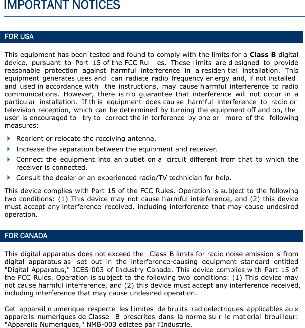


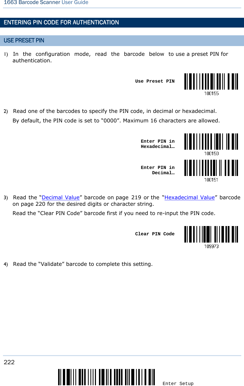
![2 Enter Setup 1663 Barcode Scanner User Guide GET FAMILIARIZED WITH 1663 AND 3610 INSTALL THE BATTERY INTO 1663 1) Hold the s canner face down in one hand, press the battery cover, and slide the battery cover. 2) Remove the battery cover. 3) Push battery lock to unlocked position. 4) Insert the battery into the battery compartment. Install the supplied 3.7V/850mAh Li-ion battery into the battery compartment. 5) Push battery lock to lock the battery firmly. 6) Replace the battery cover. 7) Hold down the [Power/Delete] key for about 2 seconds to turn on the scanner. The scanner will respond with a lon g beep (h igh tone) and its LED indicator will become solid red and go off.](https://usermanual.wiki/CipherLab/1663/User-Guide-1860865-Page-13.png)
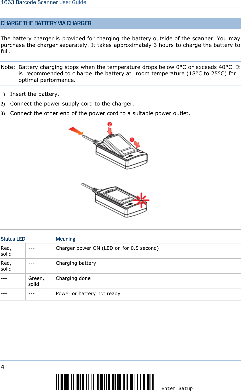
![3 Update Introduction Note: (1) To turn off the scanner, press the [Power/Delete] ke y for 2 seconds. The scanner will respond with two short beeps (h igh tone) and the LED will become solid red. Release the key. Otherwise, let the scanner t urn off automatically in specific circumstances. Refer to settings of “Auto Power Off”. (2) For shipping and storage purposes, remove the battery from the scanner. This will keep the batteries in good condition for future use. CHARGE THE BATTERY The battery may not be fully charged for shipment. For initial use, it is recommended to fully charge the battery before us ing the scanner. You can use the Direct USB cabl e to connect the scanner to PC for charging. It takes approximately 4 h ours to fully charge the battery. Refer to 1.14 Use Direct USB Cable. Note: Battery charging stops when the temperature drops below 0°C or exceeds 40°C. It is recommended to c harge the battery at room temperature (18°C to 25°C) for optimal performance. 1) Install the battery to 1663. 2) Connect 1663 to host computer or notebook via the USB cable. 3) The scanner LED will flash red during charging. When the charging is complete, the LED will turn off. When charging errors occur, the LED will turn solid red.](https://usermanual.wiki/CipherLab/1663/User-Guide-1860865-Page-14.png)
![5 Update Introduction USE 3610 The CipherLab Dongle (3610) is specifically designed fo r the scanner to com municate with a host computer cordless. The connection between the scanners and 3610 is made easy and reliable. Refer to 3.1.1 Connect to 3610. There is one LED indicator provided for communications status. Communication LED Meaning --- Blue, solid Initialize Red, solid --- Failed to establish a USB connection Red, solid Blue, flashing Serial command mode with USB Vi rtual COM: wait 3 seconds for starti ng a serial command Red, flashing Blue, flashing Serial command mode w ith USB HI D: wait 3 seconds for pre ssing [Num Lock] or [Caps Lock] 5 times via keyboard --- Blue, flashing Wait for connection request from the scanner (Slow flash at 0.5 Hz) --- Blue, flashing Connected with the scanner (Fast flash at 1 Hz) Red, solid Blue, flashing Failed to send data to host via USB Virtual COM (Fast flash at 1 Hz) Red, flashing --- Enter Download Mode](https://usermanual.wiki/CipherLab/1663/User-Guide-1860865-Page-16.png)
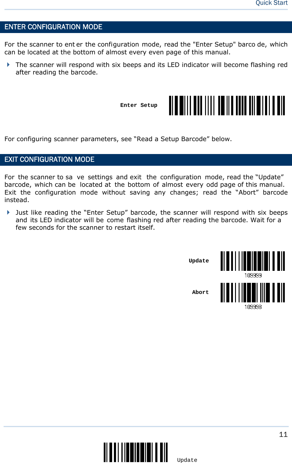
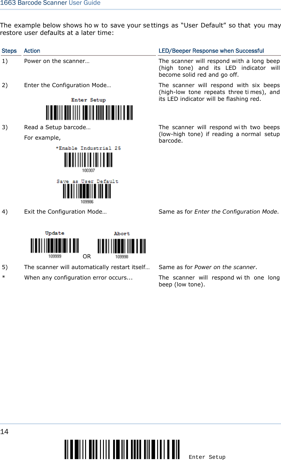
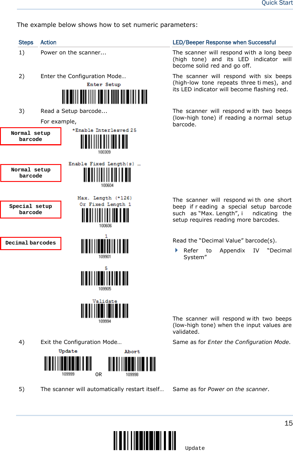
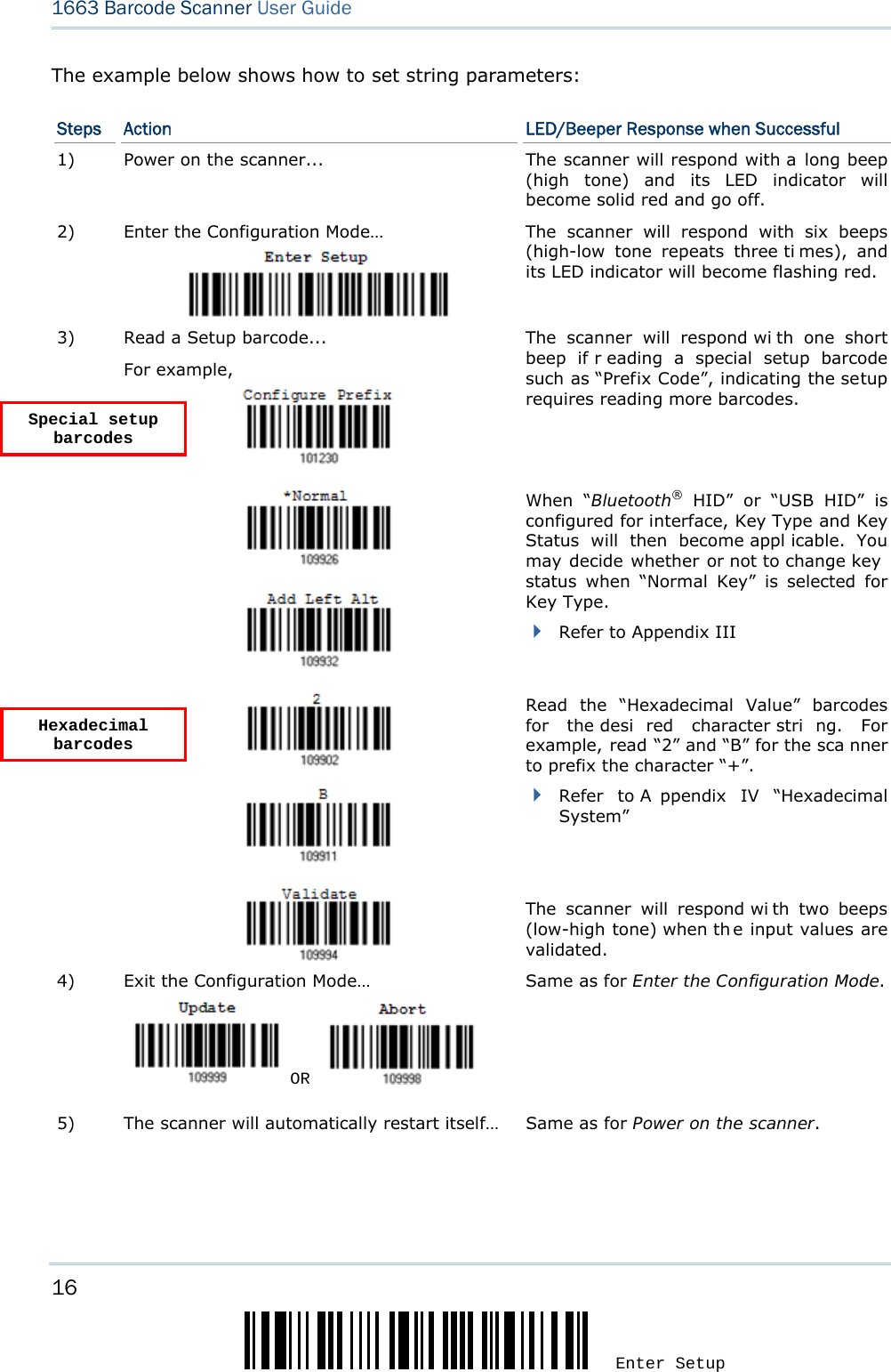
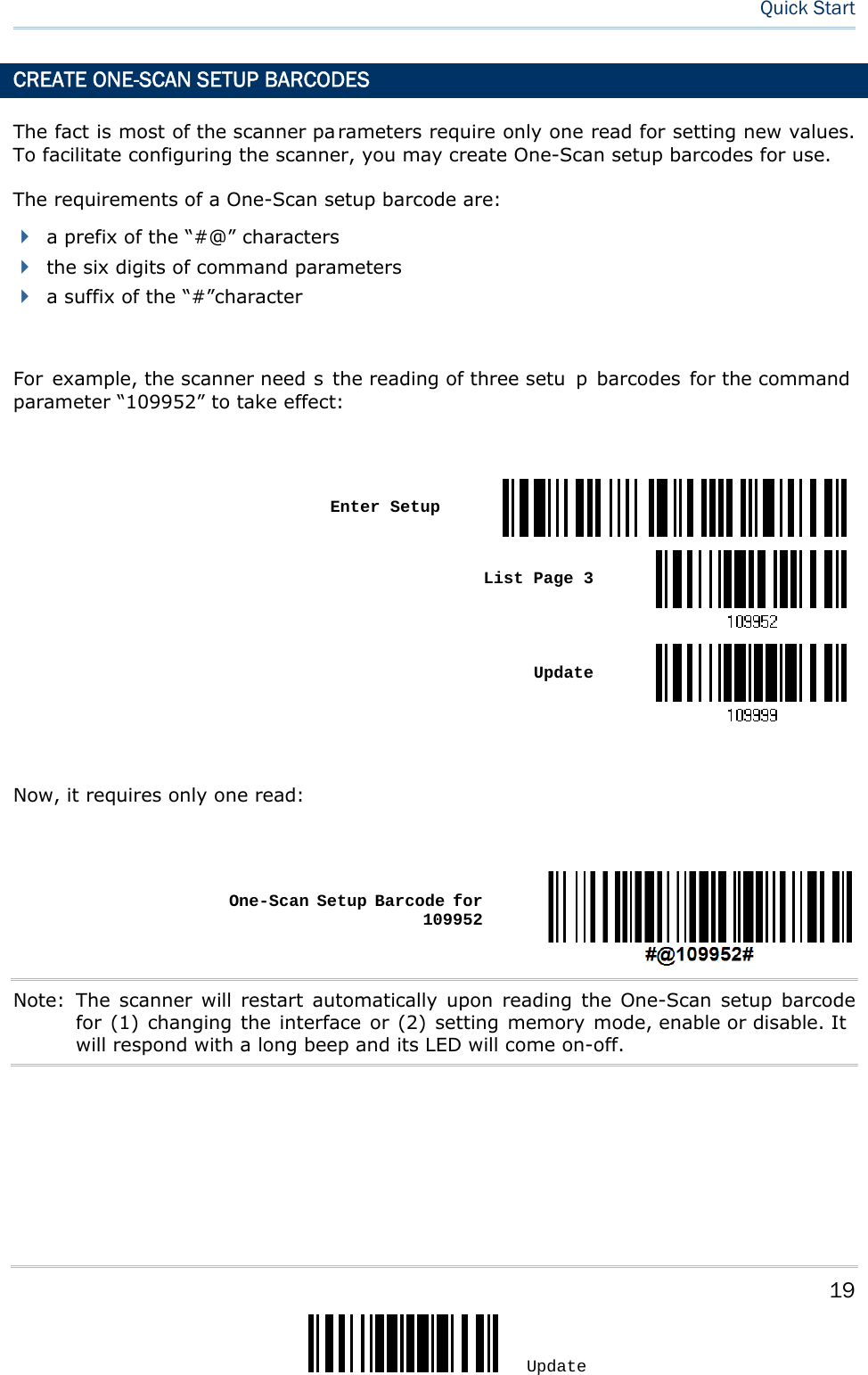
![9 Update The configuration of the scanner can be done by reading the setup barcodes contained in this manual or via the ScanMaster software. This section describes the proce dure of co nfiguring the scanner by reading the setup barcodes and provides some examples for demonstration. Configuration Mode 1) Hold down the [Power/Delete] key for 2 seconds to turn on the scanner. It will respond with a long beep and its LED will come on-off. 2) Read the “Enter Setup” barcode. It will respond with six beeps and i ts LED i ndicator will become flashing red after reading the barcode. 3) Read more setup barcodes… Most of t he setup barcodes are normal, and the scanner will respond with two beeps (low-hi gh tone). For special setup barcodes, it requires reading more than one setup barcode to complete the setting. 4) Read the “Update” or “Abort” barcode. It will respond with six beeps and its LED indicator will become flashing red after reading the barcode. 5) The scanner will restart automati cally upon reading the “Update ” or “Abort” barcode. It will respond with a long beep and its LED will come on-off. Note: Refer to Appendix II Host Serial Commands for how to configure the 3610 dongle by having the sca nner read 3610-relate d setup barcodes or using ser ial commands. QUICK START](https://usermanual.wiki/CipherLab/1663/User-Guide-1860865-Page-20.png)
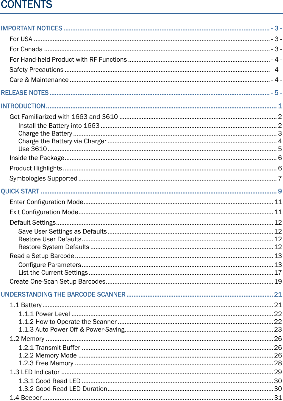
![22 Enter Setup 1663 Barcode Scanner User Guide 1.1.1 POWER LEVEL Scan the barcode below to get the battery voltage with an interval of 20%. Spare Power Level 1.1.2 HOW TO OPERATE THE SCANNER Turn on the scanner… Press the [Power/Delete] key for 2 seconds. The scanner will respond with a long beep (high tone), and its LED indicator will become solid red and go off. Turn off the scanner… Press the [Power/Delete] key for 2 seconds. The scanner will r espond with two short beeps (hi gh tone) and the LED will become solid red. Release the key then. Otherwise, let the scanner turn off automatically in specific circumstances. Delete the last collected data when in memory mode … Press the [Power/Delete] key. The scanner will respond with two short be eps (high tone) and the LED will become solid red. Before the LED goes off (within 1 second), press the [Power/Delete] key again to confirm the deletion.](https://usermanual.wiki/CipherLab/1663/User-Guide-1860865-Page-33.png)
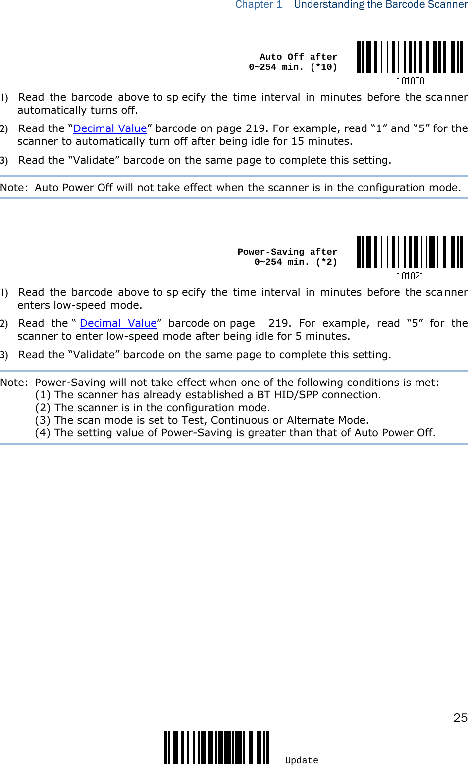
![23 Update Chapter 1 Understanding the Barcode Scanner 1.1.3 AUTO POWER OFF & POWER-SAVING The scanner will stay active at power-on, which may be followed by a transition from full CPU speed to low CPU speed (Power-Saving) to auto shutdown (Auto Power Off). Power-Saving (1~254 min.; 0= Disable): By default, it is set to stand by at full-speed for 2 minutes before it enters low-speed mode. If this feature is not desired, set it to 0. Auto Power Off (1~254 min.; 0= Disable): By default, it is set to automatically shut down after 10 minutes. If this feature is not desired, set it to 0. Note: 1. The Power-Saving setting will still take effect once a con nection has been established successfully, via Bluetooth® HID or SPP. Before establishing a WPAN connection successfully… 1) The scanner will stay active for a specified period of time (2 minutes by default) for the following scenarios. Its CPU is running at full speed, and the LED is flashing blue (On/Off ratio 0.5 s: 0.5 s). (a) waiting for a connection request from the host (Bluetooth® SPP Slave Mode) (b) trying to connect to the host (Bluetooth® HID or Bluetooth® SPP Master Mode) (c) trying to connect to 3610 2) If it fails to connect within 2 minutes, the scanner will become inactive to save power for the remaining period of ti me (the specified value minus 2 mi nutes). Its CPU i s running at l ow speed, and the LED is flashing red (On/Off ratio 0.3 s: 2.5 s). Press the [Trigger] key to wake up the scanner when it becomes inactive, and the scanner will stay active again. 3) If it fails to connect again and again, and finally stays inactive until the specified time interval for Auto Power Off has e lapsed, the scanner will automatically turn off in order to conserve battery power. Hold down the [Power/Delete] key for 2 seconds to turn it on. Note: For scenarios (a) and (b) in step 1, on your computer you may need to search for the scanner again.](https://usermanual.wiki/CipherLab/1663/User-Guide-1860865-Page-34.png)
![24 Enter Setup 1663 Barcode Scanner User Guide After establishing a WPAN connection successfully… 1) Once a WPAN connection is established successfully, the scanner will stay active for a specified period of time (2 minutes by default) for data transmission. Its CPU i s running at full speed, and the LED is flashing blue (On/Off ratio 0.02 s: 3 s). 2) If it is idle within 2 minutes, the scanner will become i nactive to save power for the remaini ng period of time (the specified value minus 2 minutes). Its CPU is running at low speed, and the LED is flashing red (On/Off ratio 0.3 s: 2.5 s). Press the [Trigger] key to wake up the scanner when it becomes inactive, and the scanner will stay active again. 3) If it is idle and finally stays inactive until the specified time interval for Auto Power Off has elapsed, the scanner will automatically turn off i n order to conserve battery power. The th ree short beeps will ring out, tone descending from high to low. Hold down the [Power/Delete] key for 2 seconds to turn it on. For Bluetooth® HID, the scanner will resume connection with the host upon powering on again, as long as the host application is running. The three short beeps will ring out, tone ascending from low to high. If the sc anner fails to resume connecti on, it will try every 5 seconds to re-connect to the host unl ess the “Reset Connecti on” barcode has been scanned. For Bluetooth® SPP Slave Mode, the scanner must wait for the host to re-connect. For Bluetooth® SPP Master Mode, the scanner will resume connection with the host upo n powering on again, as long as the host app lication is running. The three sho rt beeps will ring out, tone ascending from low to high. If the scanner fails to resume connection, it will try every 5 s econds to re-connect to the host unl ess the “Reset Connection” or “Restore System Defaults” barcode has been scanned. With the use of 361 0, the scanner wi ll try re-connecti ng to 3 610 whilst the scanner i s active.](https://usermanual.wiki/CipherLab/1663/User-Guide-1860865-Page-35.png)
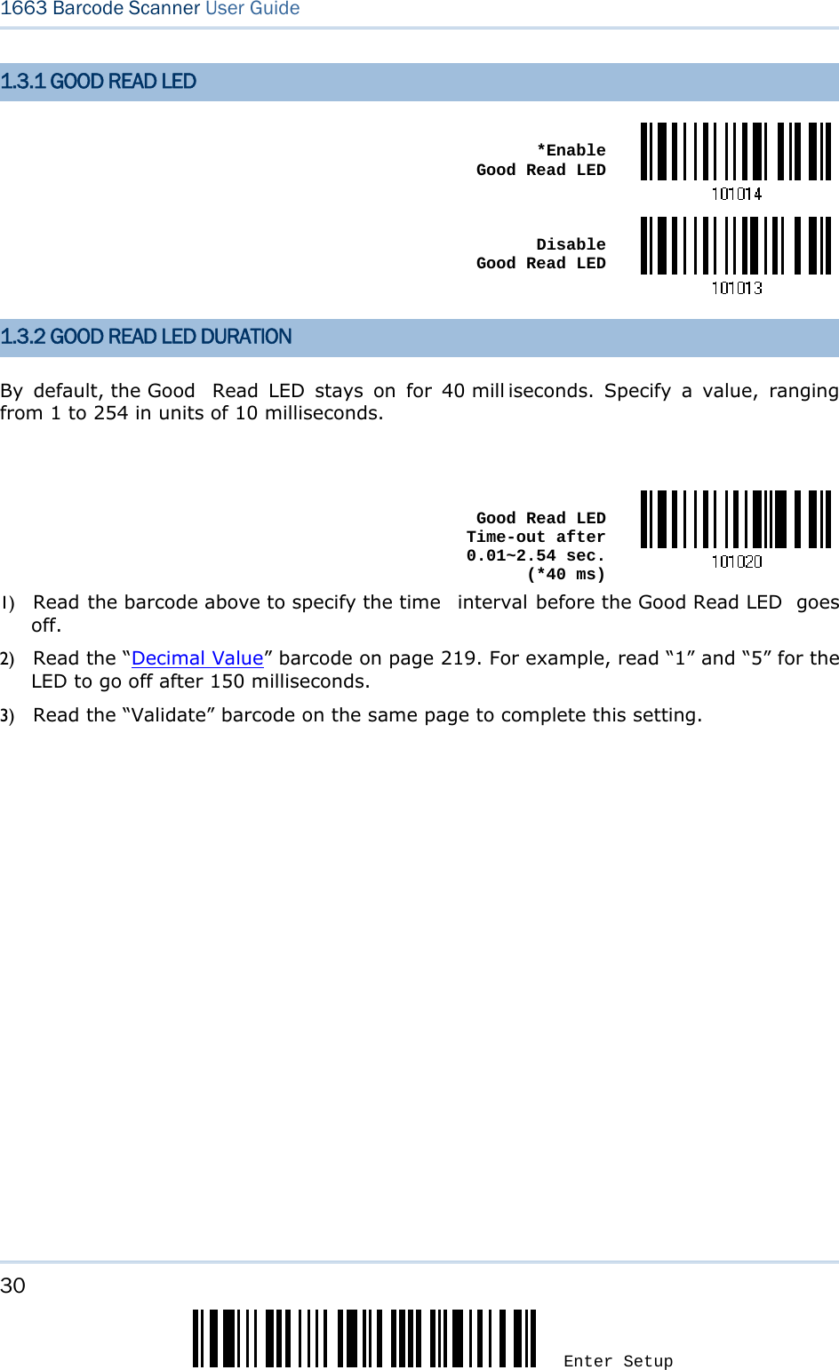
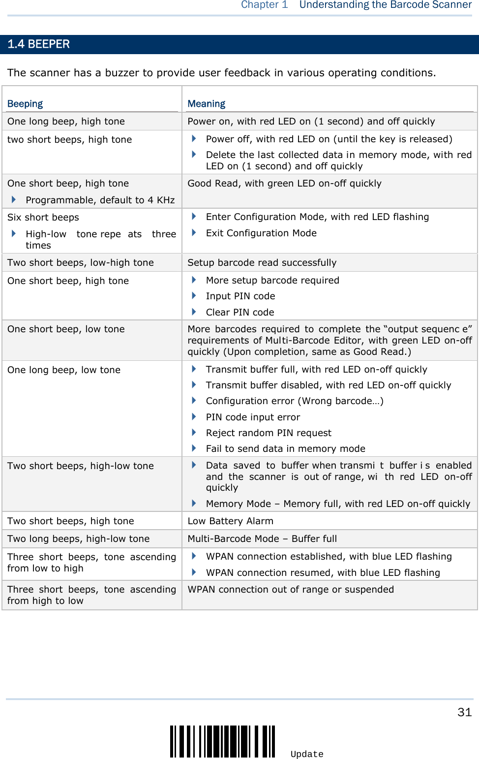
![29 Update Chapter 1 Understanding the Barcode Scanner 1.3 LED INDICATOR The triple-color LED on top of the scanner is used to provide user feedback. For example, the LED becomes soli d red and goes off upon powering on or runni ng out of transmit buffer. You may tell the difference by the beeps – you will hear a long beep of hi gh tone when powering on the scanner, and a long beep of low tone when the transmi t buffer becomes full. Scanner LED Meaning Red, on-off --- --- Power on, wi th one long beep (hi gh tone, LED on for 1 second) Data saved to buffer when transmit buffer is enabled and the scanner is out of range, with two short beeps (high-low tone) Transmit buffer full, with one long beep (low tone) Transmit buffer disabled, with one long beep (low tone) Delete the last coll ected data i n memory mode, wi th two short beeps (high tone, LED on for 1 second) Memory full in memory mode, with two short beeps (high-low tone) Red, flashing --- --- Flashing red (On/Off ratio 0.3 s: 2.5 s) i ndicates the scanner is inactive and its CPU runni ng at l ow speed to save power (because no WPAN connection is established after waiting for two minutes) Configuration Mode (On/Off ratio 0.5 s: 0.5 s) --- --- Green, on-off Good Read, with one short beep (high tone) and beeper pitch and duration programmable --- Blue, flashing --- First, flashing blue (On/Off rati o 0.5 s: 0.5 s) fo r two m inutes indicates the scanner is waiting for connection, and goes off if no connection is established, then f lashing red (On/Off rati o 0.3 s: 2.5 s) indicates the scanner is inactive. It is ready for connection only while the LED is flashing blue — SPP Slave: waiting host to connect HID or SPP Master: trying to connect to host Using 3610: trying to connect to 3610 --- Blue, flashing --- Flashing blue (On/Off rati o 0.1 s: 0.1 s) i ndicates the scanner receives a PIN code request from host (fl ashing more qui ckly than waiting connection). --- Blue, flashing --- Flashing blue (On/Off ratio 0.02 s: 3 s ) indicates the scanner has established a WPAN connection successfully. --- Blue, flashing Green, flashing Flashing blue and gr een (On/Off ratio 0.1 s: 0. 1 s) indicates an error occurs while entering the PIN code. Press the [Tri gger] key to get ready for re-connecting.](https://usermanual.wiki/CipherLab/1663/User-Guide-1860865-Page-40.png)
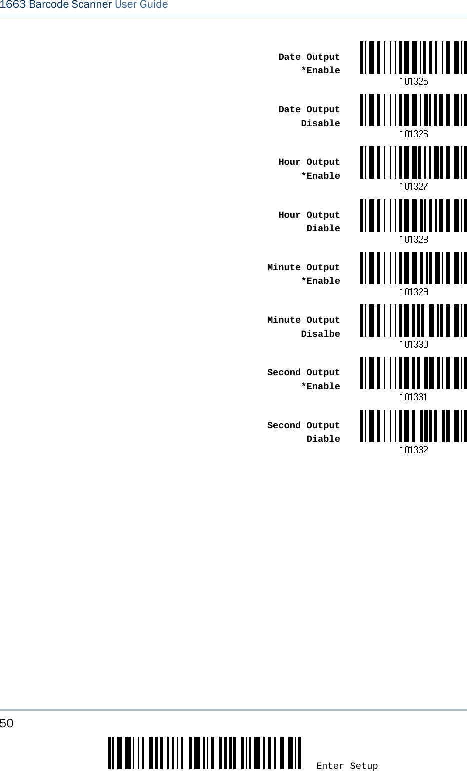
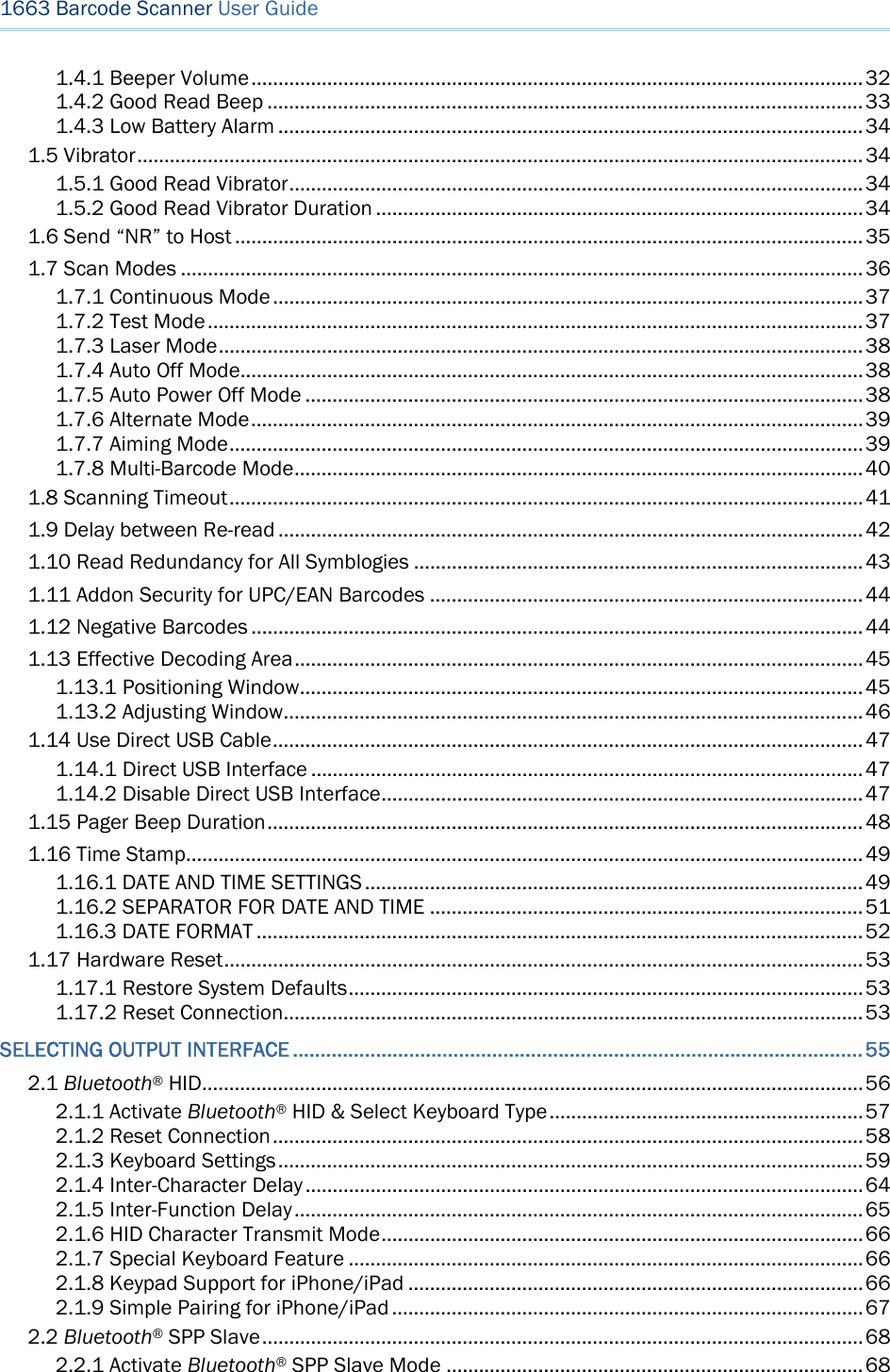
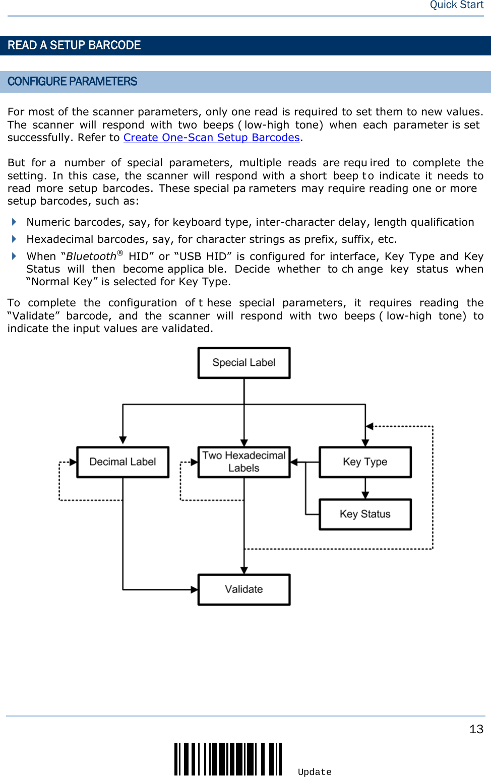
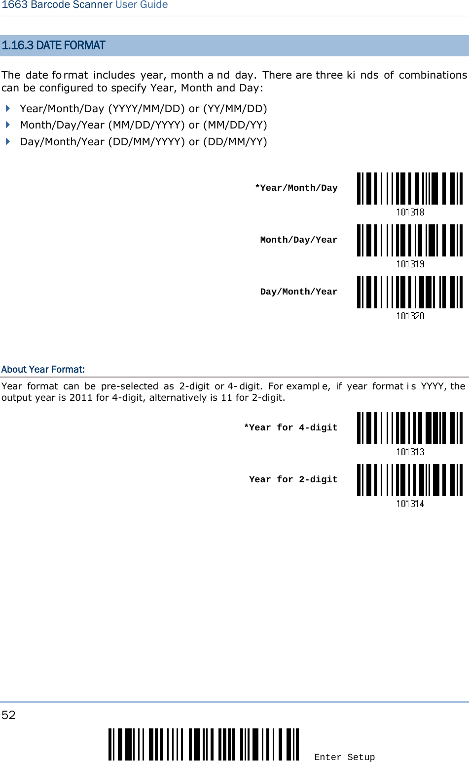
![51 Update Chapter 1 Understanding the Barcode Scanner Decoding Data and Time Year Setup Date Setup Time Setup1) Read the barcode above to apply time or date code separately, and follow steps 2~3. 2) Read the “Decimal Value” barcode on page 219 for the desired character string. Fo r example: Year: Read “2”, “0”, “1”, “1” for the year setting as year=2011. Date: Read “1”, “1”, ”2”, “0” for the date setting as date=Nov.20. Time: Read “1”, “8”, “5”, “9” for the time setting as time=18:59. 3) Read the “Validate” barcode for each setting on the same page. 1.16.2 SEPARATOR FOR DATE AND TIME The Date and Time can be split with a pre-selected separator, for example, “/” as YYYY/MM/DD or “:” as HH:MM:SS Separator for Date/Time*“-” Separator for Month/Date*“/” Separator for Hour/Minute*“:”1) Read the barcode above to apply separator to date or time separately, and fol low steps 2~3. 2) Read the “Hexadecimal Value” barcode on page 220 for the desired character string. For example, read “3” and “A” for the separator to split the data with character [:]. 3) Read the “Validate” barcode on the same page to complete this setting.](https://usermanual.wiki/CipherLab/1663/User-Guide-1860865-Page-62.png)
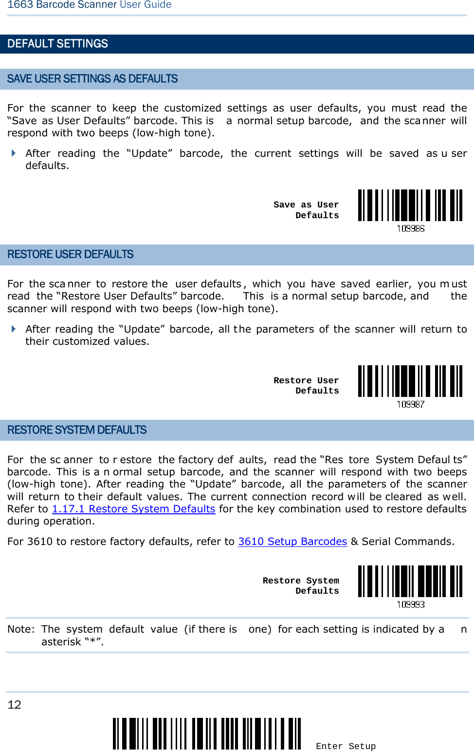
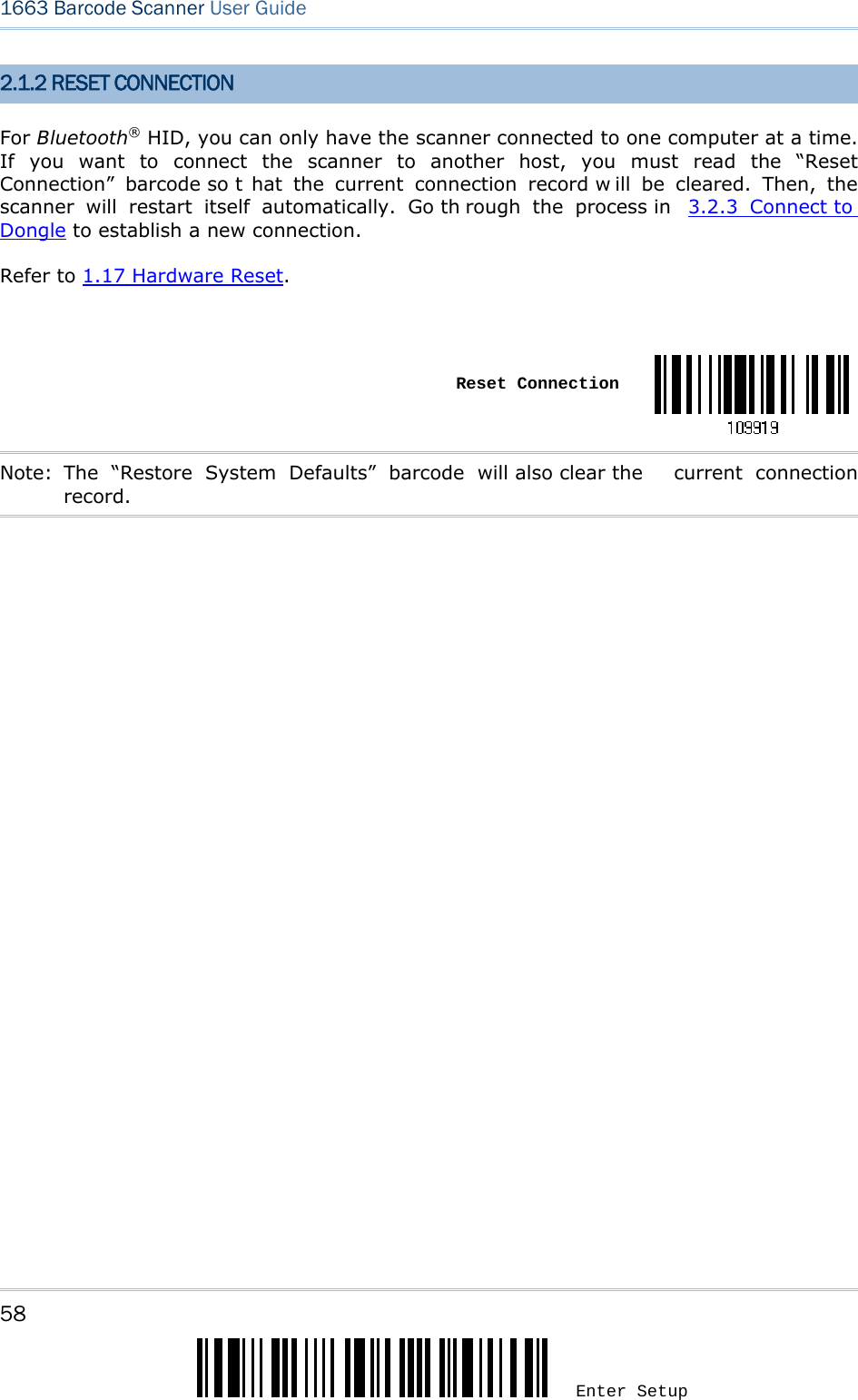
![53 Update Chapter 1 Understanding the Barcode Scanner 1.17 HARDWARE RESET 1.17.1 RESTORE SYSTEM DEFAULTS In addition to using the “Restore System Defaults” barcode, the following procedure using key combinations, can be used to restore the system defaults during operation. 1) Hold down the [Power/Delete] key. 2) When the scanner responds with two short beeps (high tone), press the [Trigger] key for 5 seconds. The scanner LED indicator becomes solid red and then goes off. 3) When the scanner responds with a long beep (high tone), release the keys. Its LED indicator becomes solid red and goes off. Note: The scanner will restart itself automatically. 1.17.2 RESET CONNECTION When the output interface is Bluetooth® HID or Bluetooth® SPP Master, the scanner will attempt to maintain an establ ished connection. To stop such re-connection, read the “Reset Connection” or “Restore System Defaults” barcode to clear the current connection record. Alternatively, use the key combination as described below to reset connection during operation. 1) Hold down the [Trigger] key, a nd then pr ess the [Powe r/Delete] key for at l east 5 seconds. 2) The scanner will respond wi th two short beeps (hi gh tone). Wait until the scanner responds with a long beep (high tone), release the keys. Note: After resetting connection by hardware, the scanner will not restart itself automatically. It will resume to its previous operation except no connection.](https://usermanual.wiki/CipherLab/1663/User-Guide-1860865-Page-64.png)

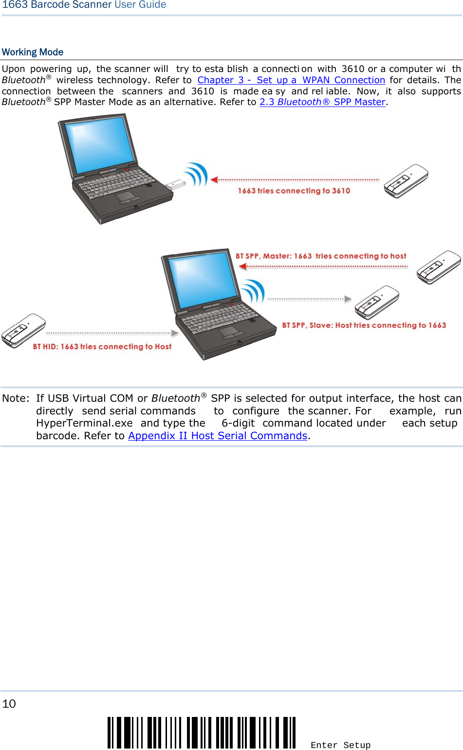
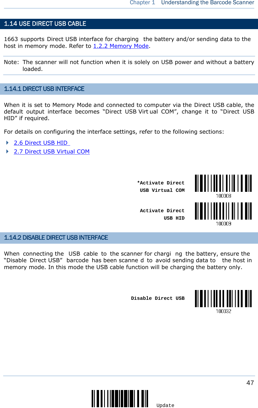
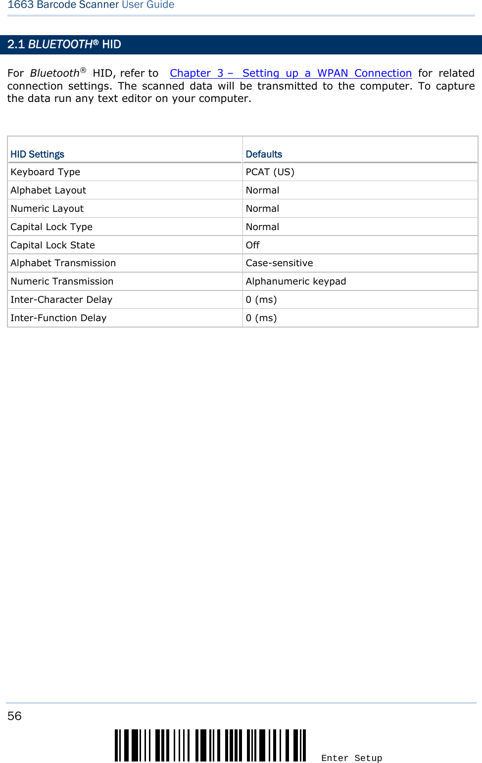
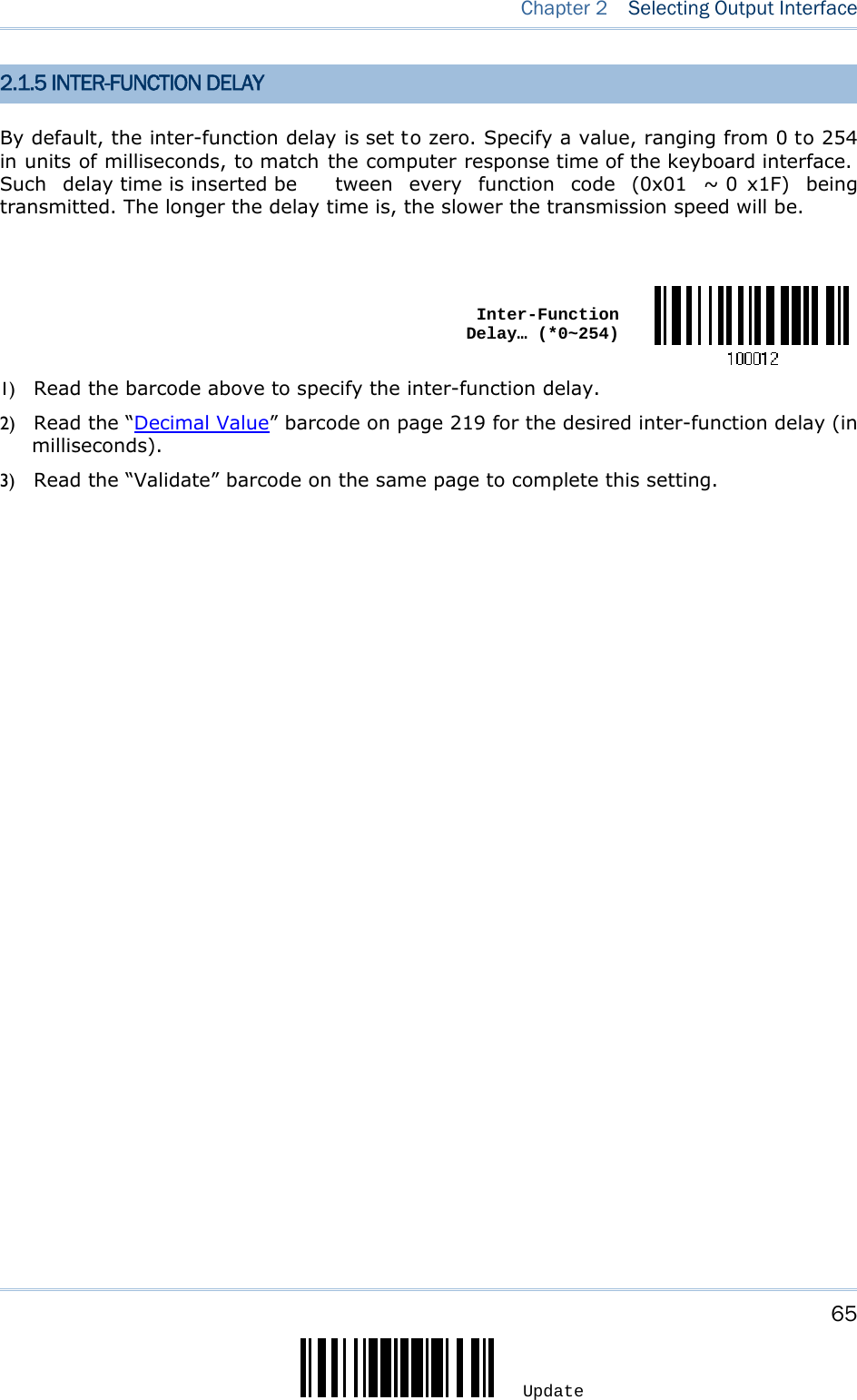
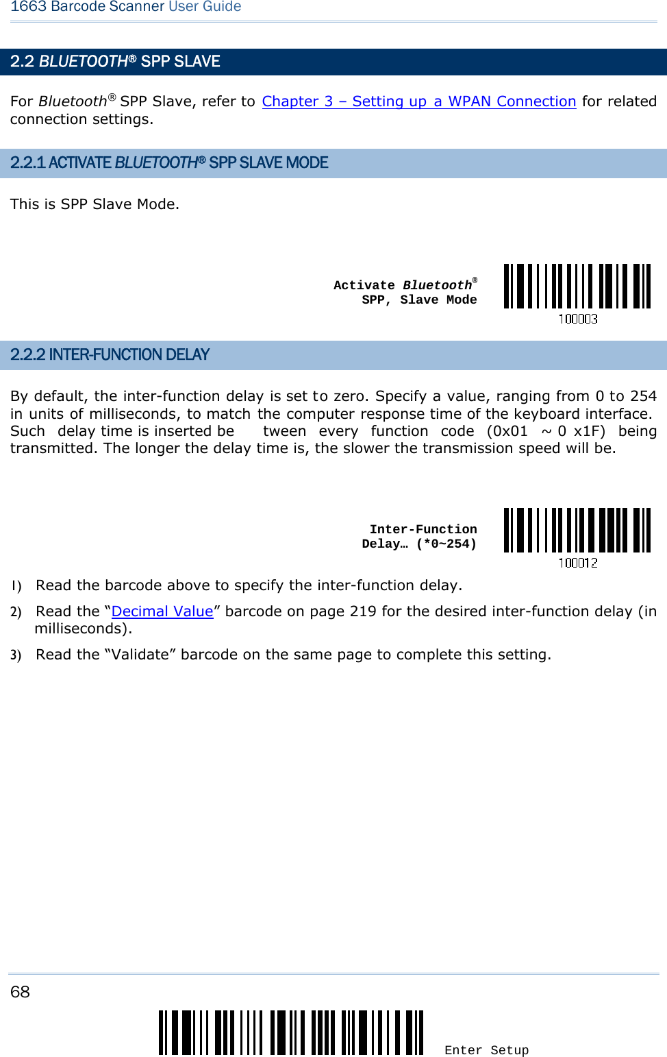
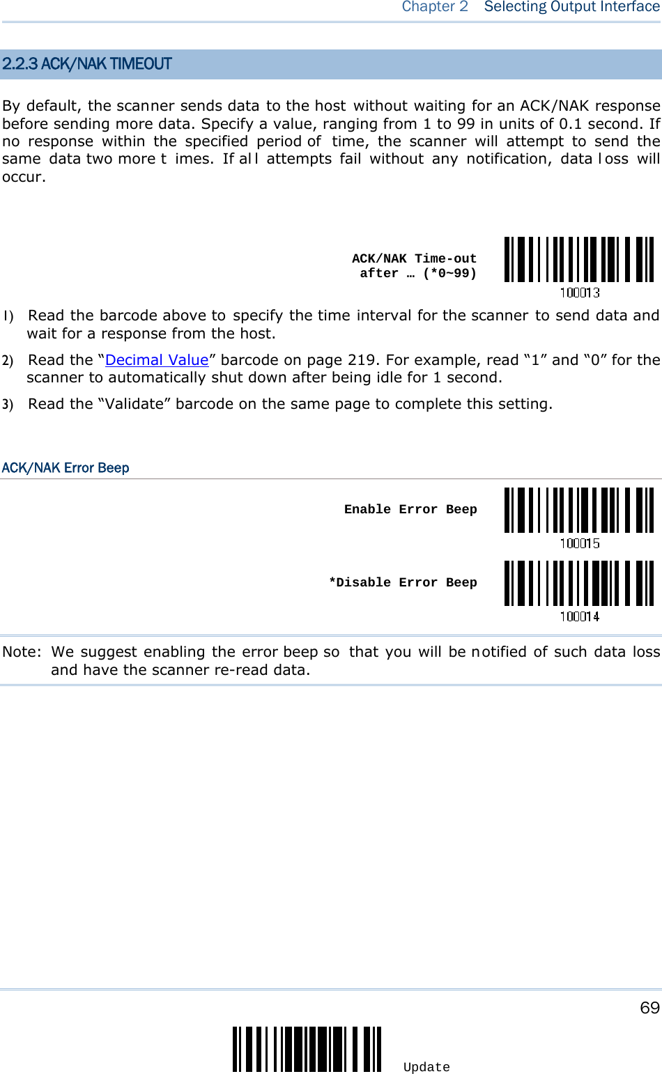
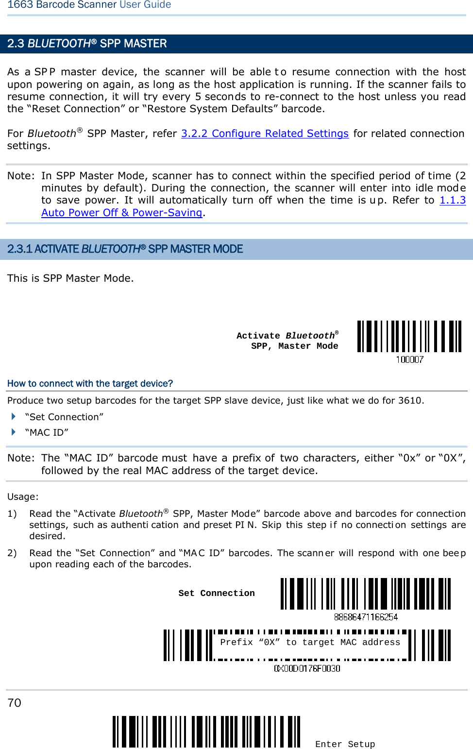
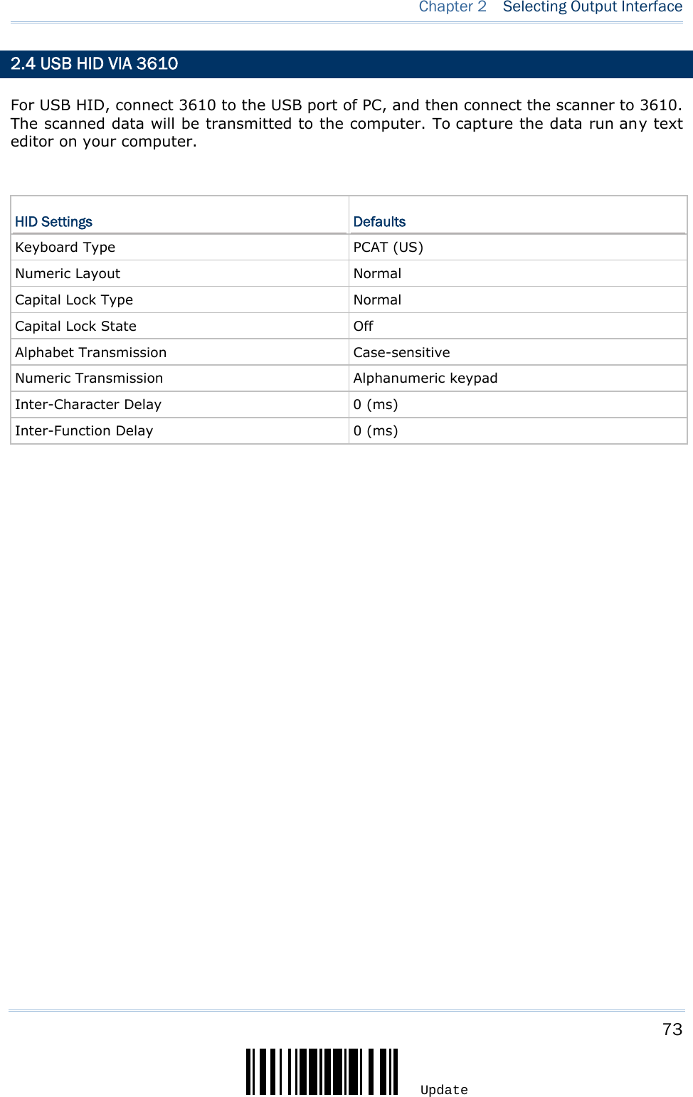
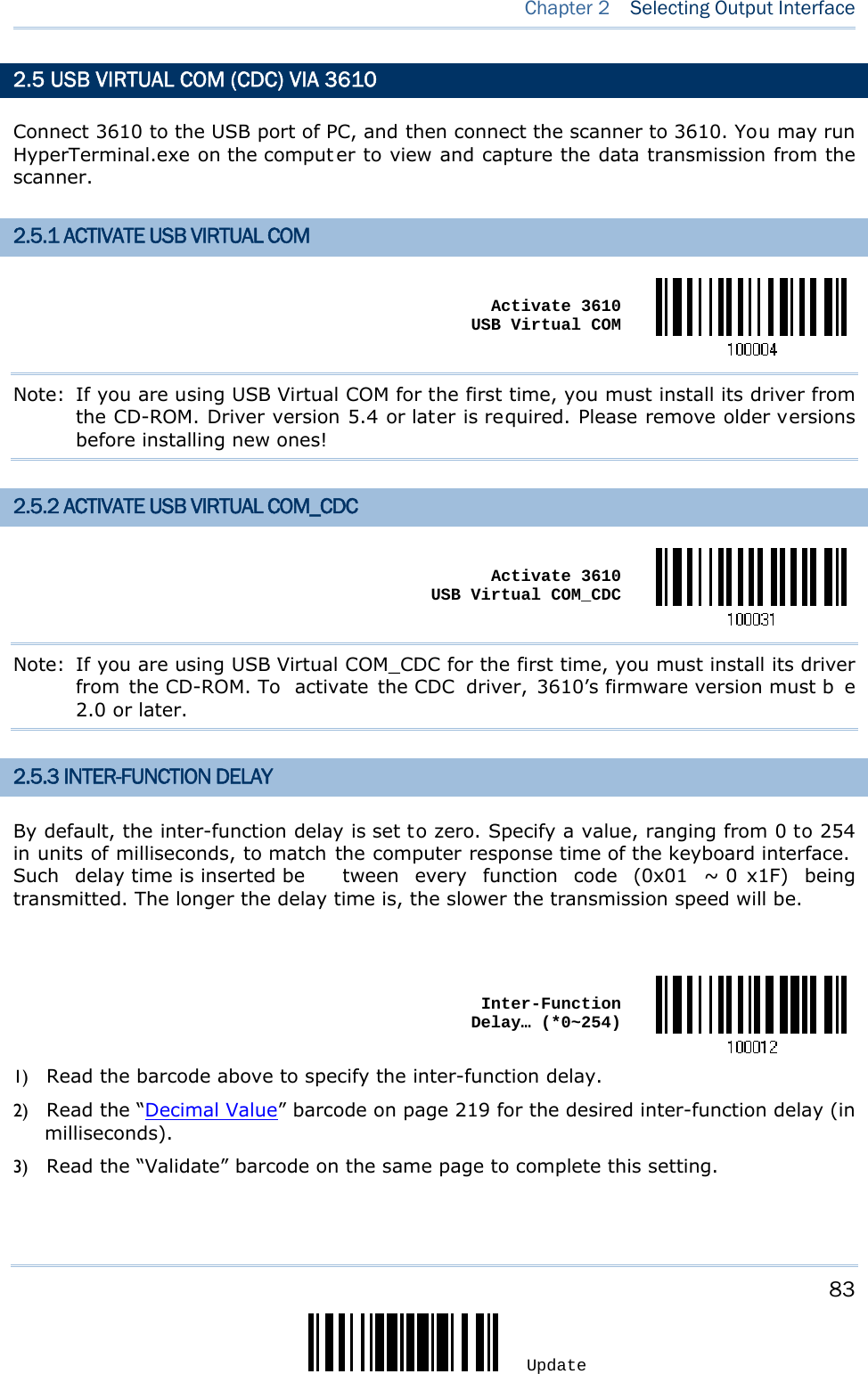
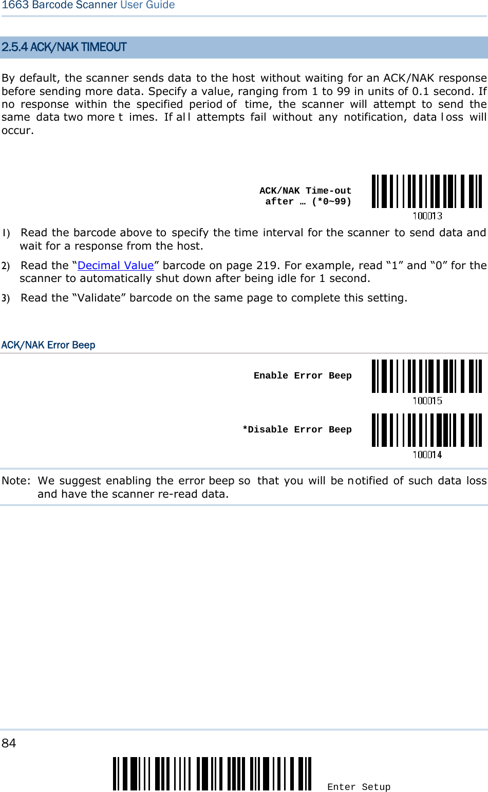
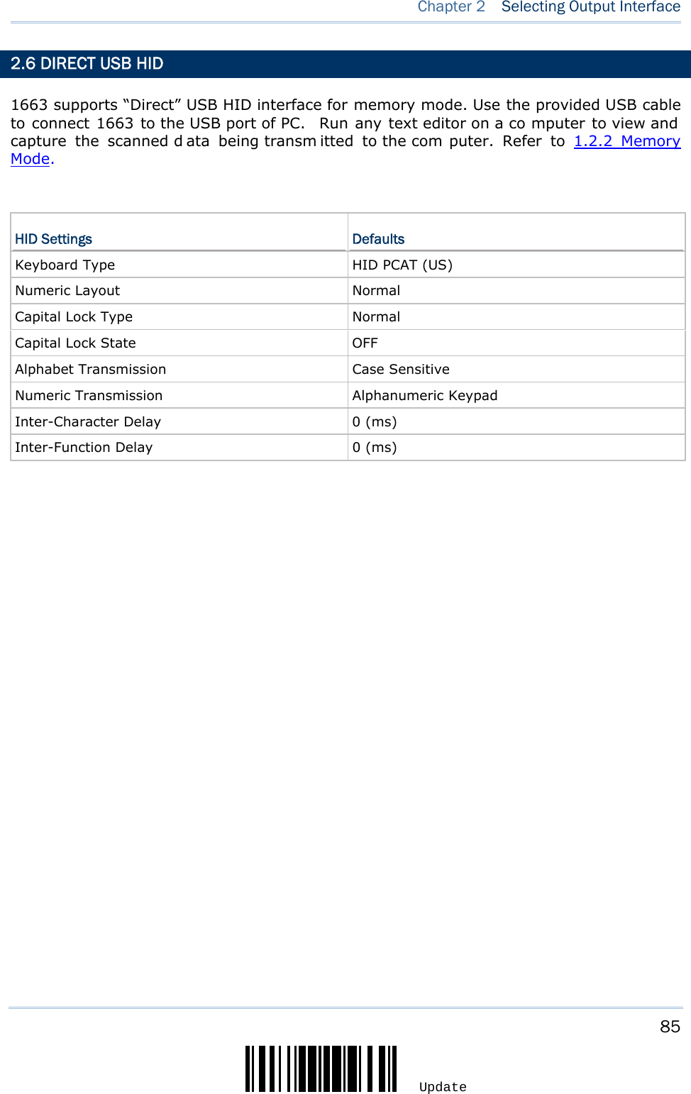
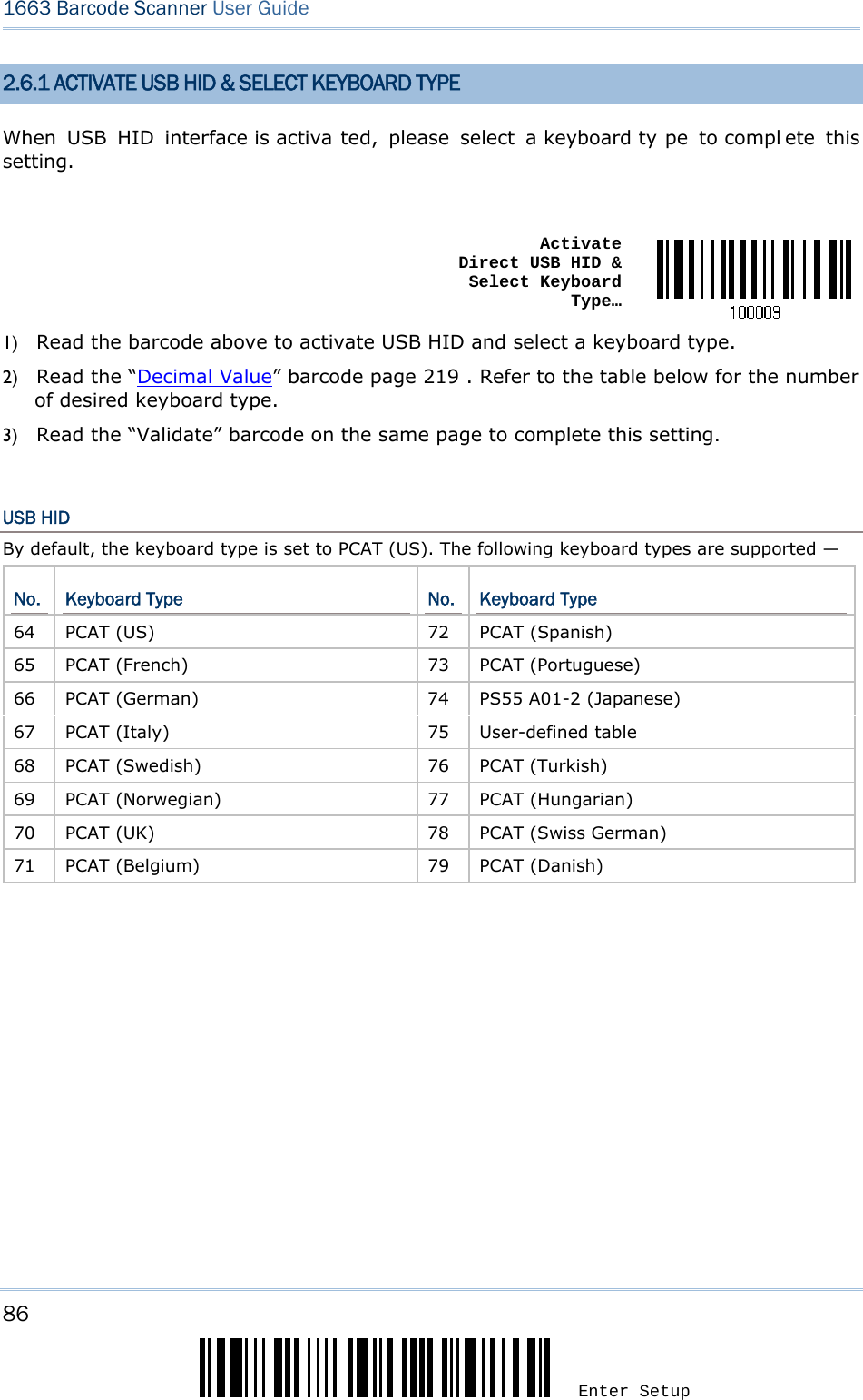
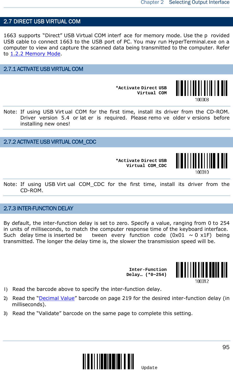
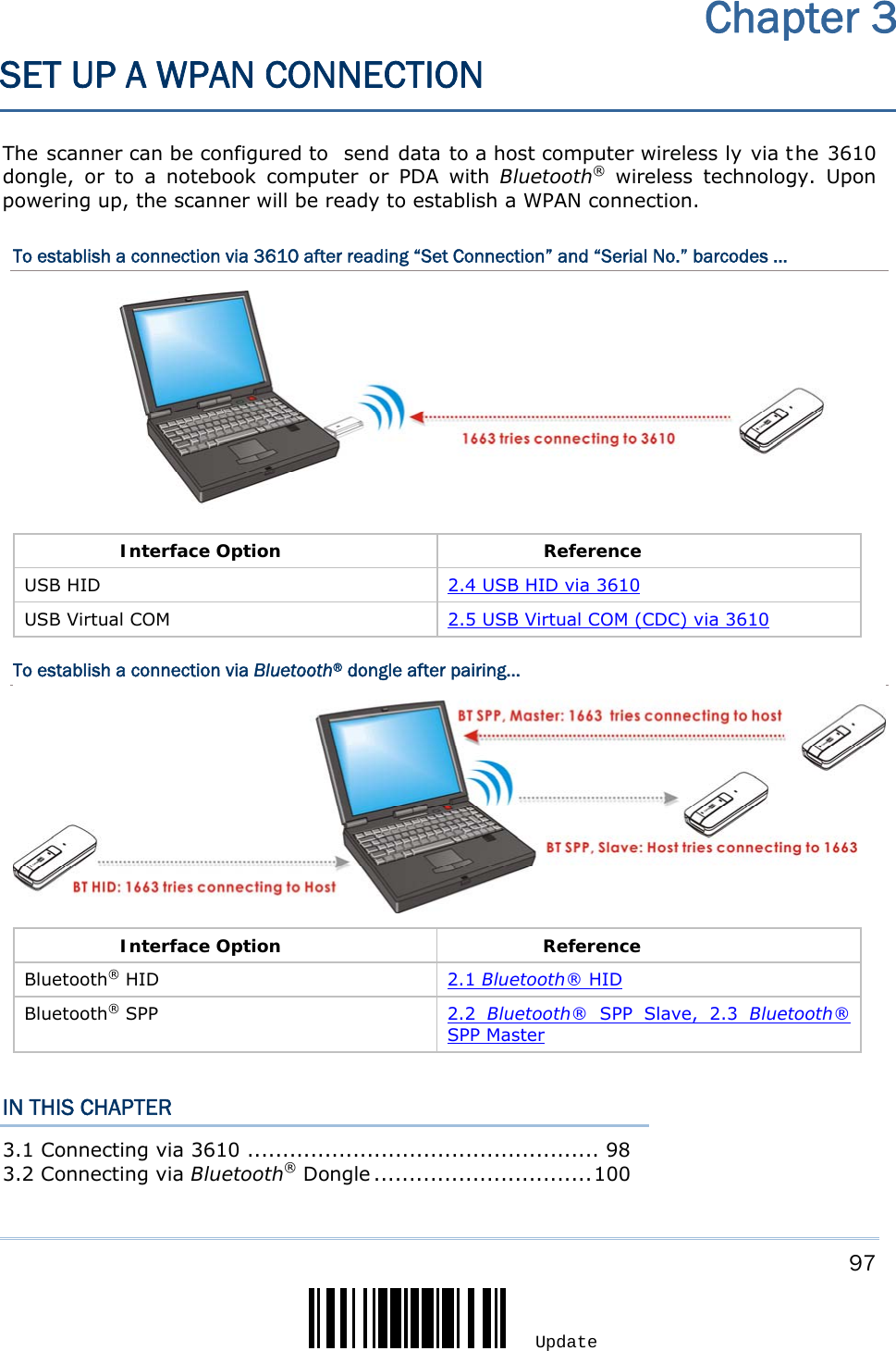
![55 Update In order to establish a proper co nnection between host computer and the scanner, we suggest following these instructions – 1) Install battery and hold down the [Power/Delete] key for 2 seconds to t urn on the scanner. 2) Read the “Enter Setup” barcode to enter the configuration mode. 3) Read the associated barcodes to activate the desired interface. See the following sections for output interfaces supported. 4) Read the barcodes for related settings. 5) Read the “Update” barcode to exit the configuration mode. 6) Turn on host computer or laptop and establish a WPAN connection with the scanner. Refer to Chapter 3 – Setting up a WPAN Connection. Note: (1) By default, the output interface is set to “Bluetooth® HID”. (2) When set to Memory Mode and con nected to computer via the Direct US B cable, the default output interface becomes “Direct USB Virtual COM”. IN THIS CHAPTER 2.1 Bluetooth® HID......................................................... 56 2.2 Bluetooth® SPP Slave ................................................. 67 2.3 Bluetooth® SPP Master .............................................. 70 2.4 USB HID via 3610...................................................... 73 2.5 USB Virtual COM (CDC) via 3610 ................................. 83 2.6 Direct USB HID.......................................................... 85 2.7 Direct USB Virtual COM............................................... 95 Chapter 2 SELECTING OUTPUT INTERFACE](https://usermanual.wiki/CipherLab/1663/User-Guide-1860865-Page-66.png)
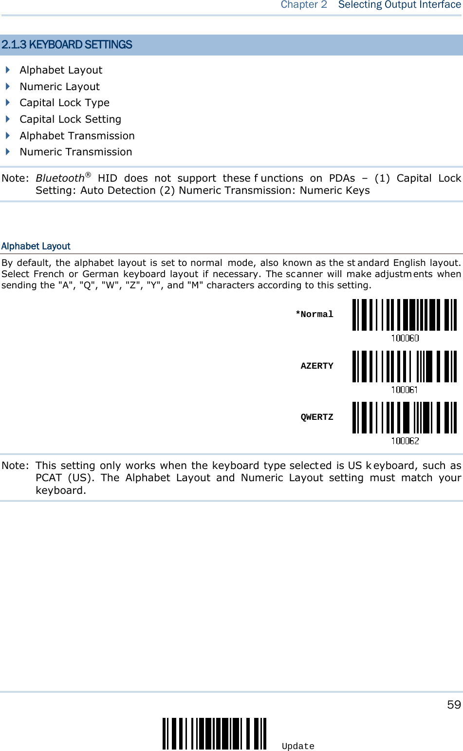

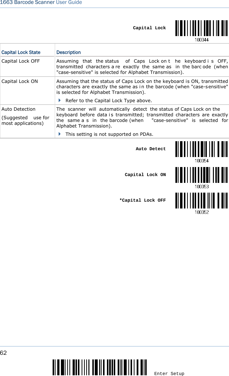
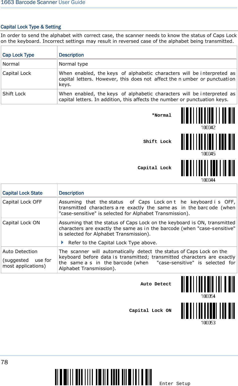
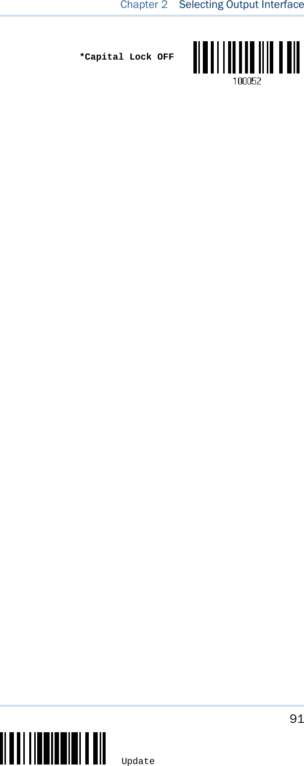
![61 Update Chapter 2 Selecting Output Interface Numeric Layout Select a proper l ayout that matches the al phabet layout. The scanner will make a djustments according to this setting. Options Description Normal Depends on the [Shift] key or [Shift Lock] setting Lower Row For QWERTY or QWERTZ keyboard Upper Row For AZERTY keyboard *Normal Upper Row Lower RowNote: This setting is to be used with the Character Substitution setting when support for certain keyboard types (languages) is unavailable but required. Capital Lock Type & Setting In order to send the alphabet with correct case, the scanner needs to know the status of Caps Lock on the keyboard. Incorrect settings may result in reversed case of the alphabet being transmitted. Cap Lock Type Description Normal Normal type Capital Lock When enabled, the keys of alphabetic characters will be i nterpreted as capital letters. However, this does not affect the n umber or punctuati on keys. Shift Lock When enabled, the keys of alphabetic characters will be i nterpreted as capital letters. In addition, this affects the number or punctuation keys. *Normal Shift Lock](https://usermanual.wiki/CipherLab/1663/User-Guide-1860865-Page-72.png)
![63 Update Chapter 2 Selecting Output Interface Alphabet Transmission By default, the alphabet transmission is case-sensitive, meaning that th e alphabet will be transmitted according to the original case, the status of Caps Lock on the keyboard, as well as the Capital Lock setting. Select [Ignore Case] to have alphabet transmitted according to the status of Caps Lock on the keyboard only. Ignore Case *Case-sensitive Refer to 5.1 Letter Case.](https://usermanual.wiki/CipherLab/1663/User-Guide-1860865-Page-74.png)
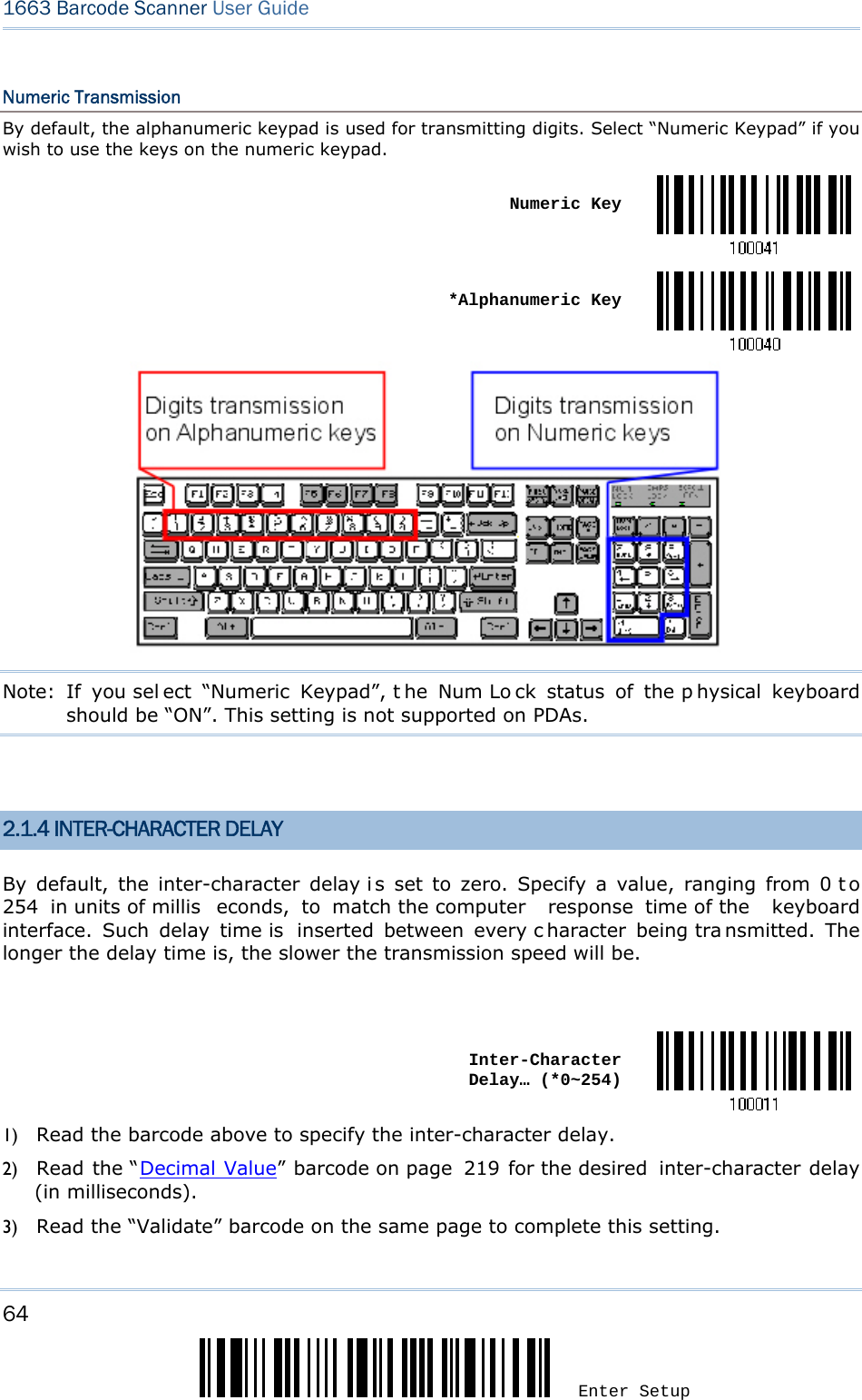
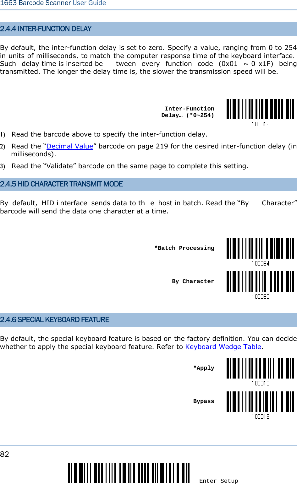
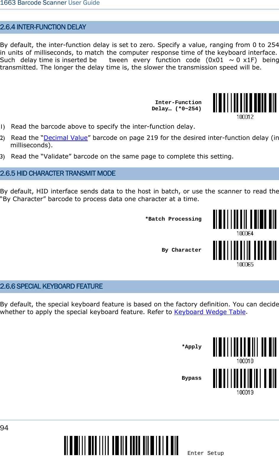
![66 Enter Setup 1663 Barcode Scanner User Guide 2.1.6 HID CHARACTER TRANSMIT MODE By default, HID i nterface sends data to the host i n batch. You may read the “By Character” barcode to process data one character at a time. *Batch Processing By CharacterNote: “By Character” transmit mode is required when working with iPhone or iPad. 2.1.7 SPECIAL KEYBOARD FEATURE By default, the special keyboard feature is based on the factory definition. You can decide whether to apply the special keyboard feature. Refer to Keyboard Wedge Table. *Apply Bypass2.1.8 KEYPAD SUPPORT FOR IPHONE/IPAD When the scanner has been successfully connected to iPhone or iPad for data collection, the onscreen keypad of iPhone or iPad will disappear. Read the “Use POWER Key to Show or Hide Keypad” barcod e in advance. Then, it will allow pressing the [Power/Delete] key to show or hide the onscreen keypad. *Normal](https://usermanual.wiki/CipherLab/1663/User-Guide-1860865-Page-77.png)
![67 Update Chapter 2 Selecting Output Interface Use POWER Key to Show or Hide KeypadIn addition to using the [Power/Delete] key, you may also show or hide the keypad by reading the following barcode. Show or Hide KeypadNote: This function only works for (1) iPhone 4 and 3GS version 4.1 or later, and (2) iPad version 4.2 or later. 2.1.9 SIMPLE PAIRING FOR IPHONE/IPAD The required windo w of pairing passcode is always po p-up when you are using a Bluetooth® connection to iPhone or iPad. Scan the barcode below to enable Bluetooth® simple pairing for iOS so that the passcode required window will not be appeare d during a connection. You can connect to iPhone/iPad more quickly. By def ault, this function is set to Disable. *Disable EnableNote: Simple pairing only supports to the device with Bluetooth® v2.1 or later.](https://usermanual.wiki/CipherLab/1663/User-Guide-1860865-Page-78.png)
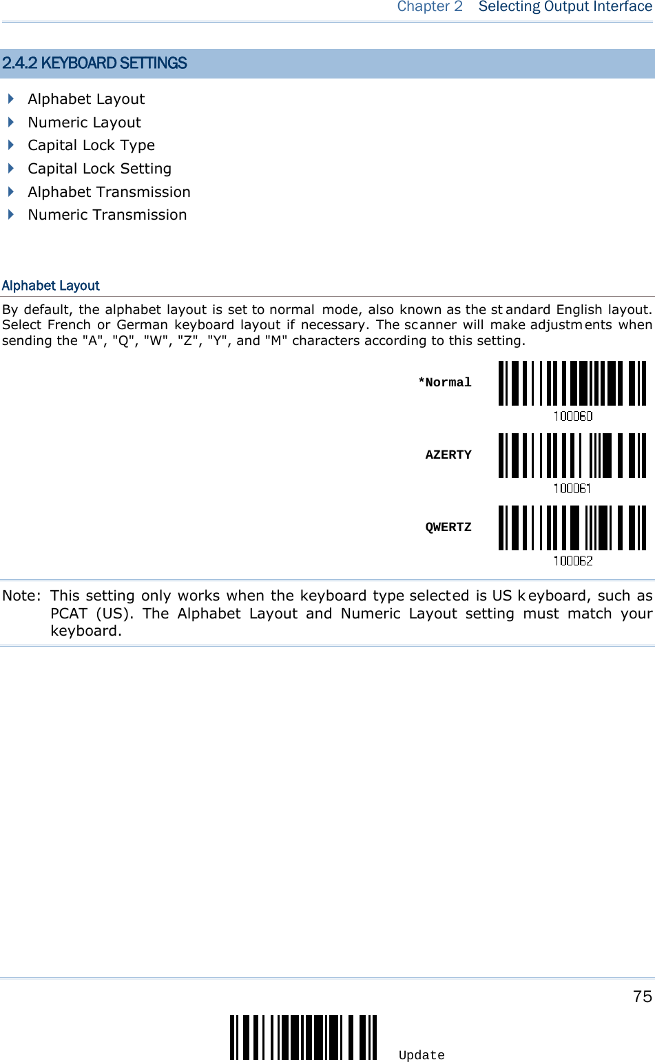

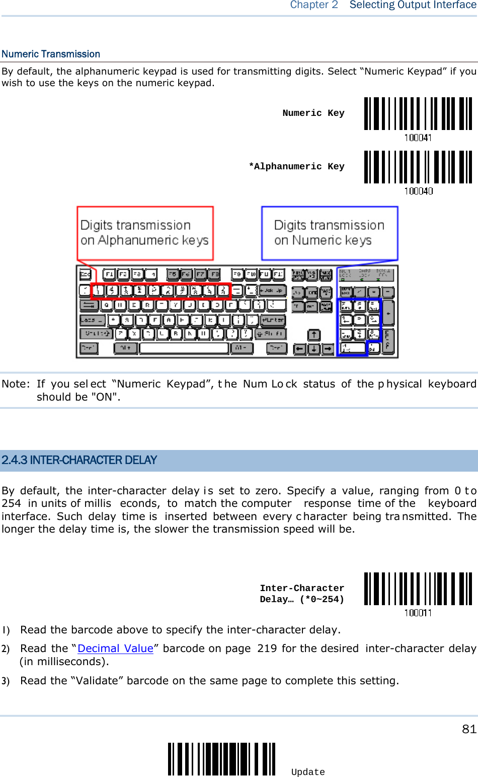
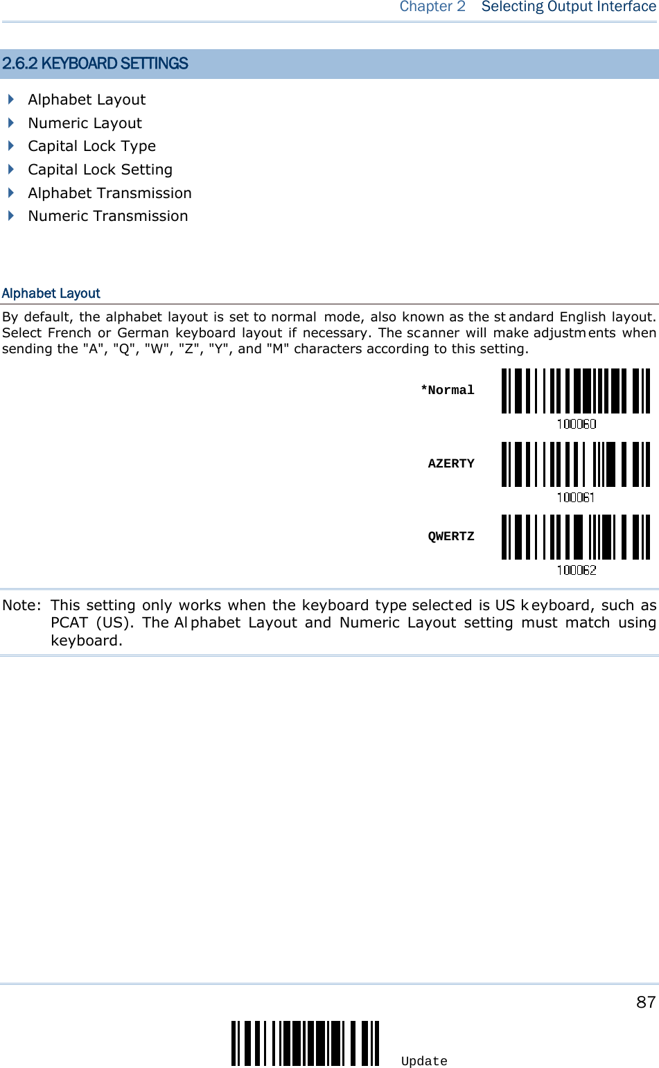
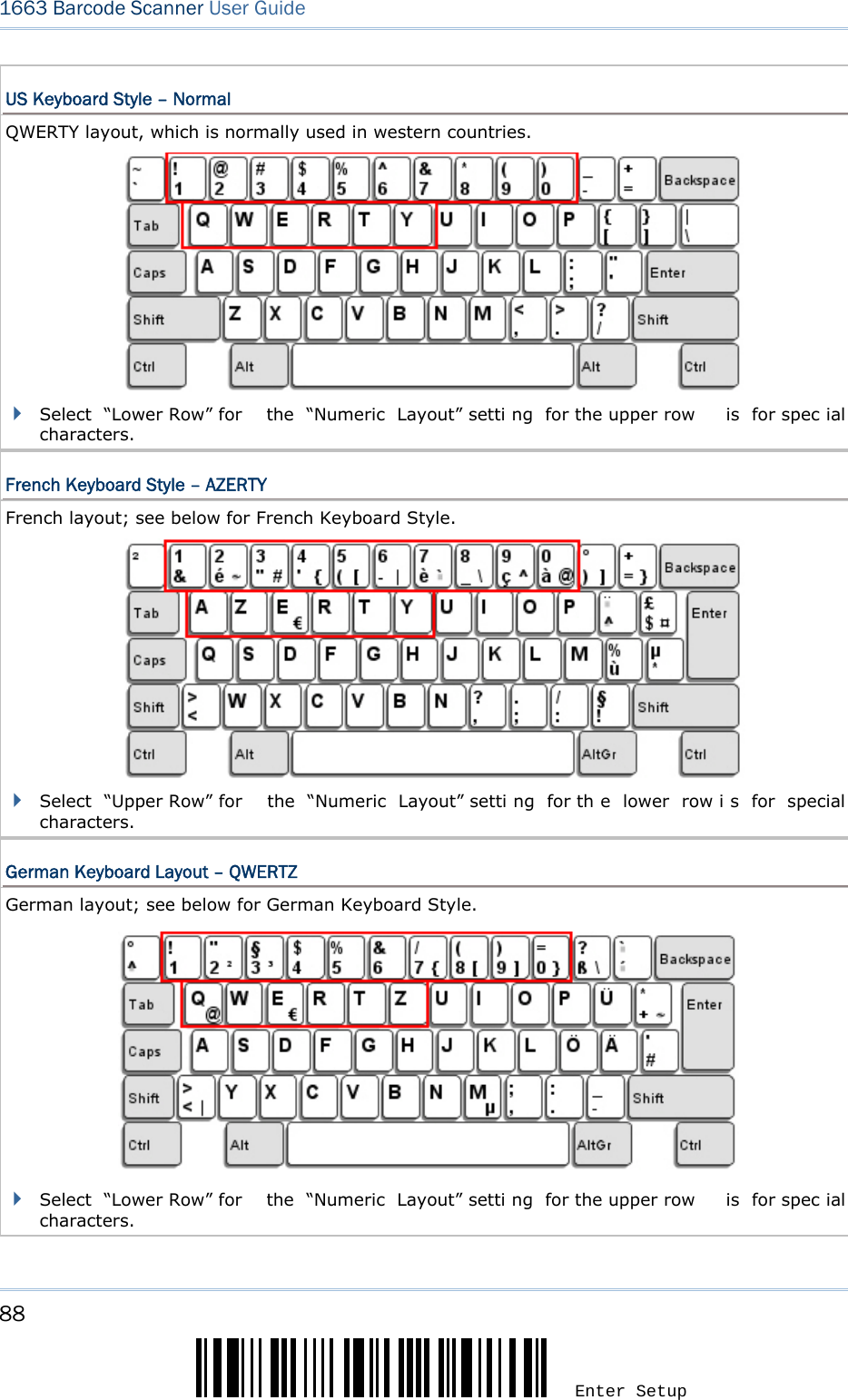
![77 Update Chapter 2 Selecting Output Interface Numeric Layout Select a proper l ayout that matches the al phabet layout. The scanner will make a djustments according to this setting. Options Description Normal Depends on the [Shift] key or [Shift Lock] setting Lower Row For QWERTY or QWERTZ keyboard Upper Row For AZERTY keyboard *Normal Upper Row Lower RowNote: This setting is to be used with the Character Substitution setting when support for certain keyboard types (languages) is unavailable but required.](https://usermanual.wiki/CipherLab/1663/User-Guide-1860865-Page-88.png)

![80 Enter Setup 1663 Barcode Scanner User Guide Alphabet Transmission By default, the alphabet transmission is case-sensitive, meaning that th e alphabet will be transmitted according to the original case, the status of Caps Lock on the keyboard, as well as the Capital Lock setting. Select [Ignore Case] to have alphabet transmitted according to the status of Caps Lock on the keyboard only. Ignore Case *Case-sensitive Refer to 5.1 Letter Case.](https://usermanual.wiki/CipherLab/1663/User-Guide-1860865-Page-91.png)
![89 Update Chapter 2 Selecting Output Interface Numeric Layout Select a proper l ayout that matches the al phabet layout. The scanner will make a djustments according to this setting. Options Description Normal Depends on the [Shift] key or [Shift Lock] setting Lower Row For QWERTY or QWERTZ keyboard Upper Row For AZERTY keyboard *Normal Upper Row Lower RowNote: This setting is to be used with the Character Substitution setting when support for certain keyboard types (languages) is unavailable but required.](https://usermanual.wiki/CipherLab/1663/User-Guide-1860865-Page-100.png)

![92 Enter Setup 1663 Barcode Scanner User Guide Alphabet Transmission By default, the alphabet transmission is case-sensitive, meaning that th e alphabet will be transmitted according to the original case, the status of Caps Lock on the keyboard, as well as the Capital Lock setting. Select [Ignore Case] to have alphabet transmitted according to the status of Caps Lock on the keyboard only. Ignore Case *Case-sensitive Refer to 5.1 Letter Case.](https://usermanual.wiki/CipherLab/1663/User-Guide-1860865-Page-103.png)

![104 Enter Setup 1663 Barcode Scanner User Guide 3.2.3 CONNECT TO DONGLE The procedure goes through associating devices for establ ishing a WPAN co nnection, which is pretty much the same except for the software you are using. If your computer is running Microsoft® Windows® XP (SP1 to SP3), Windows Vista® Service Pack 1 (SP1) and Windows 7, y ou can use t he software support that Windows ® includes, or y ou can u se the driver that the device manufacturer pr ovides. Now, l et’s try using the software support that Windows® XP Service Pack 2 includes. Bluetooth® HID Procedure By default, Bluetooth® HID is activated on the scanner, and the keyboard type is set to PCAT (US). When Bluetooth® HID is re-activated, you will have to select a keyboard type to complete this setting. The procedure is the same as for Bluetooth® SPP. Refer to steps 1~11 below. Bluetooth® SPP Procedure 1) Turn on the Bluetooth® function on your computer, running Windows XP SP2. 2) Double-click the Bluetooth® icon from the lower right of the taskbar. Alternatively, you may go to Control Panel > Bluetooth Devices. 3) Click [Add] to search devices nearby.](https://usermanual.wiki/CipherLab/1663/User-Guide-1860865-Page-115.png)
![105 Update Chapter 3 Set up a WPAN Connection 4) Turn on the scanner with correct WPAN settings, such as select Bluetooth® SPP or Bluetooth® HID, broadcasting enabled, authentication enabled, and PIN c ode specified, etc. Select the check box of [My device is set up and ready to be found] on your computer. 5) Click [Next]. 6) Wait for a few seconds for the Wizard to search available devices nearby. The scanner will appear with its “serial number” as the device name. You may doubl e-check the “Serial Number” label on the scanner to ens ure connecting with the correct scan ner. Select the ta rget scanner. If the target scanner does not appear on the list, click [Search Again] to refresh the list. The scanner might enter Suspend Mode now, and you can press the trigger to have it active again (=discoverable). It will then stay active for a specified period of time (2 minutes by default) and wait for PC to establish a connection.](https://usermanual.wiki/CipherLab/1663/User-Guide-1860865-Page-116.png)
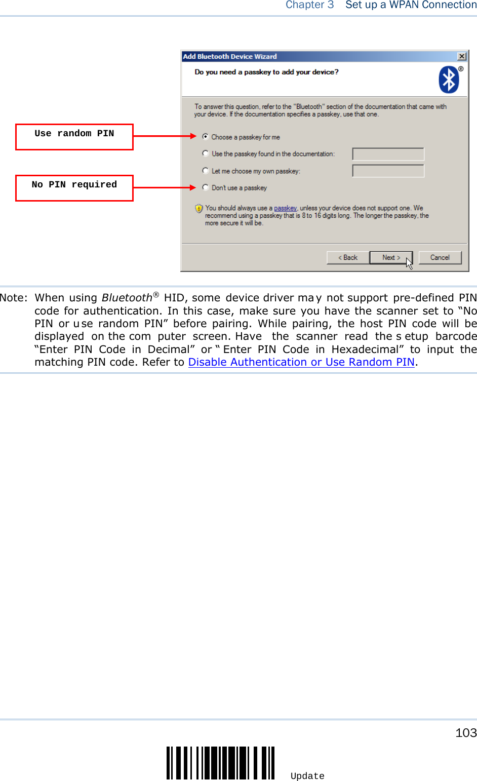
![106 Enter Setup 1663 Barcode Scanner User Guide 7) Click [Next]. 8) Enter the passkey for authentication, which must be exactly the same as configured for the scanner.](https://usermanual.wiki/CipherLab/1663/User-Guide-1860865-Page-117.png)
![107 Update Chapter 3 Set up a WPAN Connection 9) Click [Next]. Wait for a few seconds for Windows to exchange passkeys.](https://usermanual.wiki/CipherLab/1663/User-Guide-1860865-Page-118.png)
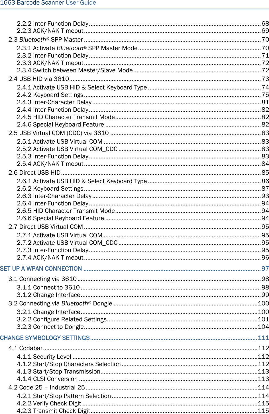
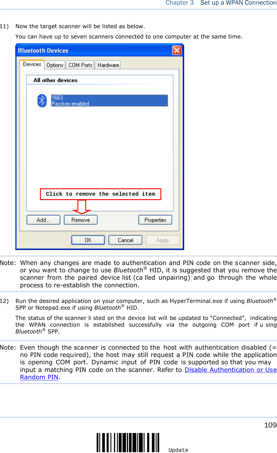
![108 Enter Setup 1663 Barcode Scanner User Guide Note: When Bluetooth security is enabled without pr oviding a pre-set PIN code, dynamic input of PIN code is supported. 10) Click [Finish]. 1663as Bluetooth® SPP Slave1663as Bluetooth® SPP Master](https://usermanual.wiki/CipherLab/1663/User-Guide-1860865-Page-119.png)
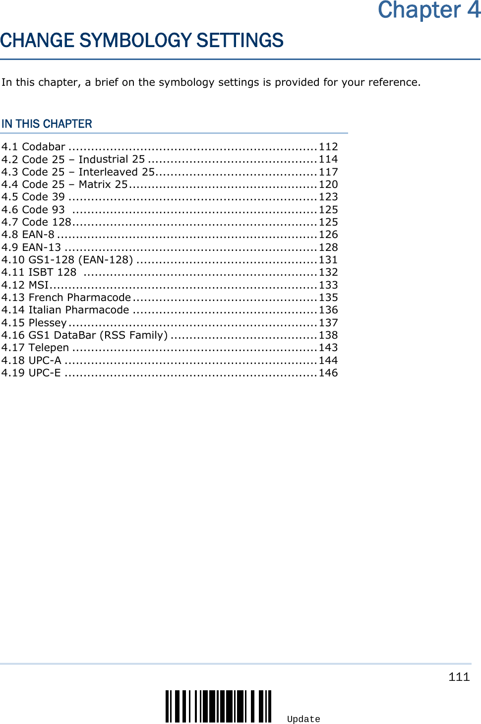
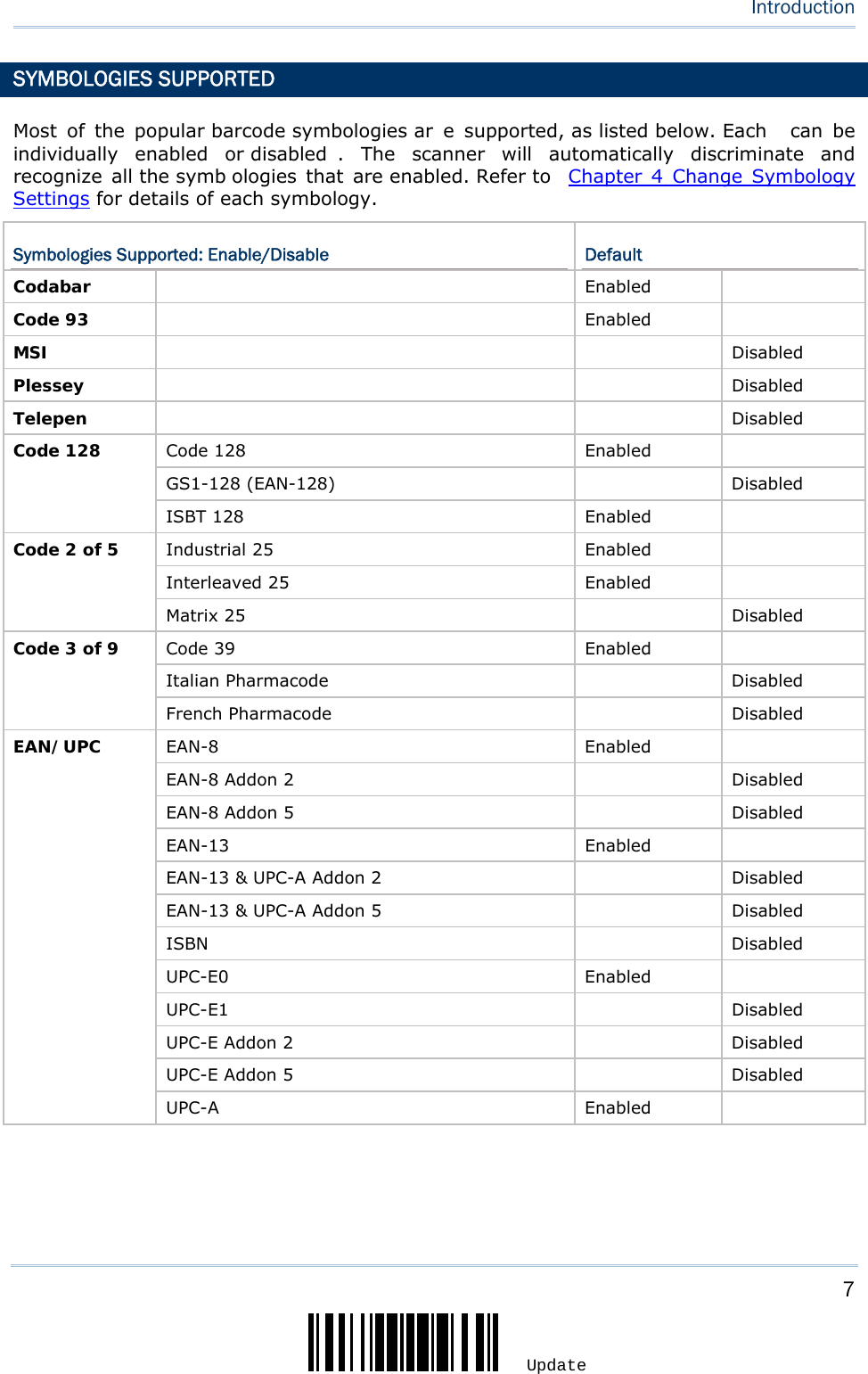
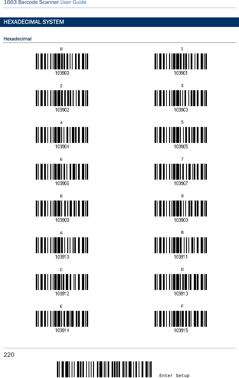
![131 Update Chapter 4 Change Symbology Settings 4.10 GS1-128 (EAN-128) *Enable DisableNote: GS1-128 barcodes can be decoded only when this setting is enabled. However, for 1660 with firmware version no later than 1.30, GS1-128 barcodes are taken a s Code 128 when this setting is disabled. 4.10.1 CODE ID TRANSMISSION Decide whether to include the Code ID ("]C1") in the data being transmitted. Transmit Code ID *Do Not Transmit4.10.2 FIELD SEPARATOR (GS CHARACTER) Decide whether to apply a field separator (to convert the FNC1 control character to human readable character). Enable Field Separator…18) Read the barcode above to enable field separator. 19) Read the “Hexadecimal Value” barcode on page 220 for the desired character string. 20) Read the “Validate” barcode to complete this setting. Note: GS1-128 barcodes start with the FNC1 control character to distinguish themselves from other uses of Code 128. FNC1 is also used to separate data fields in the GS1-128 barcodes.](https://usermanual.wiki/CipherLab/1663/User-Guide-1860865-Page-142.png)
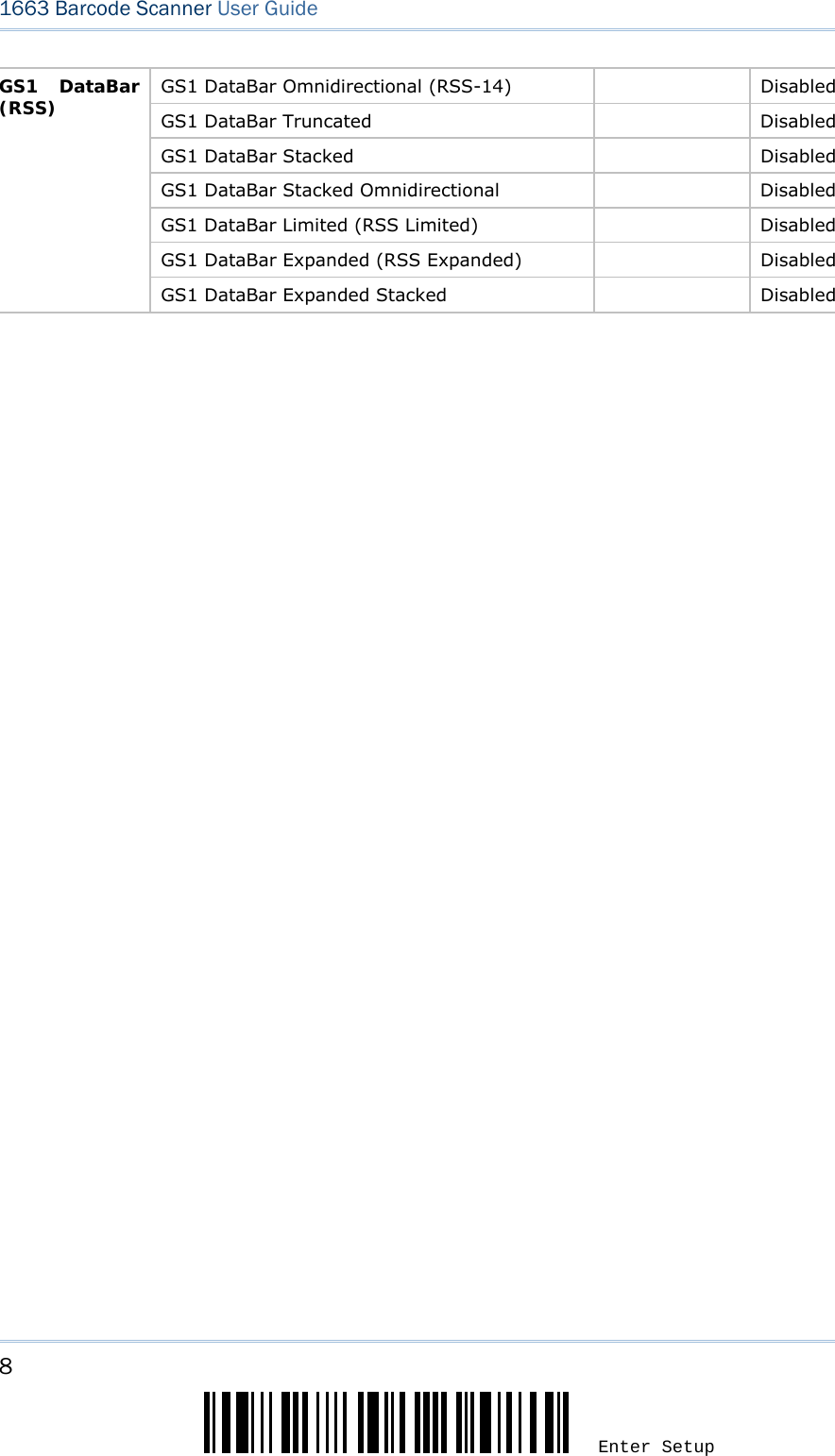
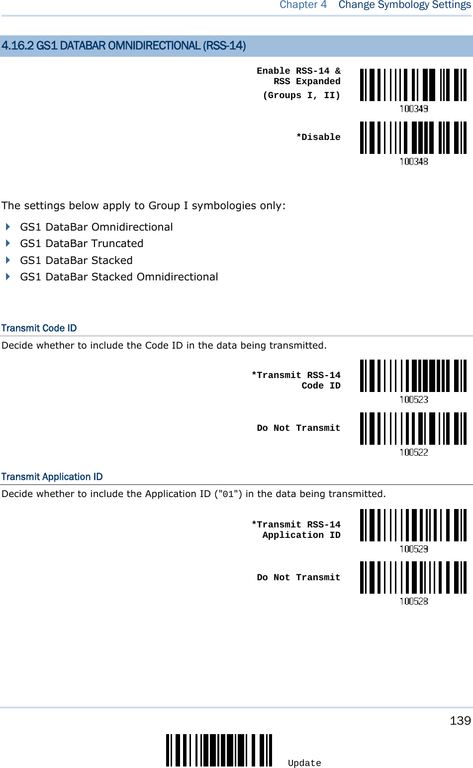
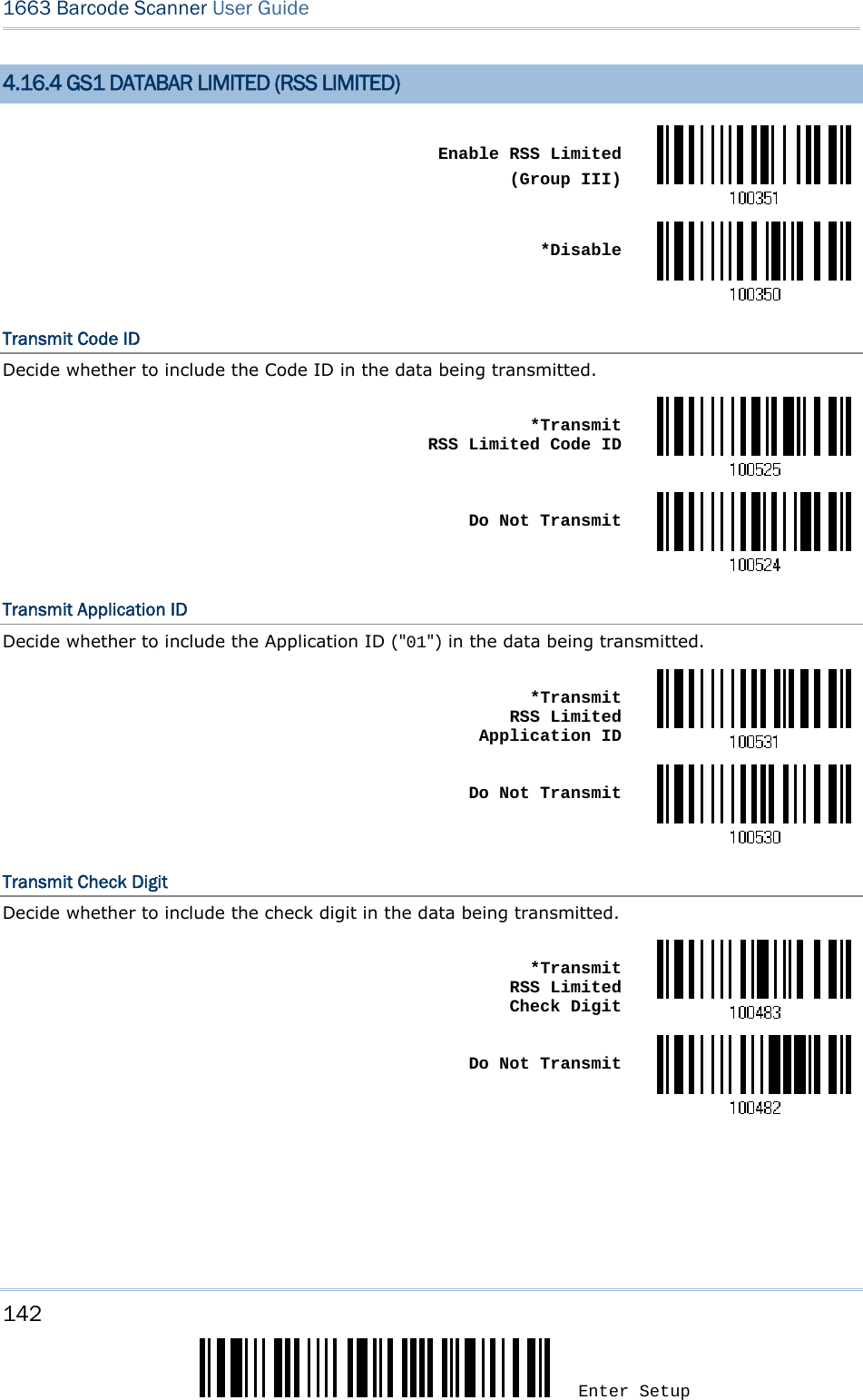
![138 Enter Setup 1663 Barcode Scanner User Guide 4.16 GS1 DATABAR (RSS FAMILY) It is categorized into three groups: Group I — GS1 DataBar Omnidirectional (RSS-14) This group consists of the following: GS1 DataBar Omnidirectional GS1 DataBar Truncated GS1 DataBar Stacked GS1 DataBar Stacked Omnidirectional Group II — GS1 DataBar Expanded (RSS Expanded) This group consists of the following: GS1 DataBar Expanded GS1 DataBar Expanded Stacked Group III — GS1 DataBar Limited (RSS Limited) This group consists of the following: GS1 DataBar Limited 4.16.1 CODE ID SELECTION Select a desired Code ID to use: “]e0“ (GS1 DataBar Code ID) “]C1” (GS1-128 Code ID) Use “]C1” *Use “]e0”](https://usermanual.wiki/CipherLab/1663/User-Guide-1860865-Page-149.png)
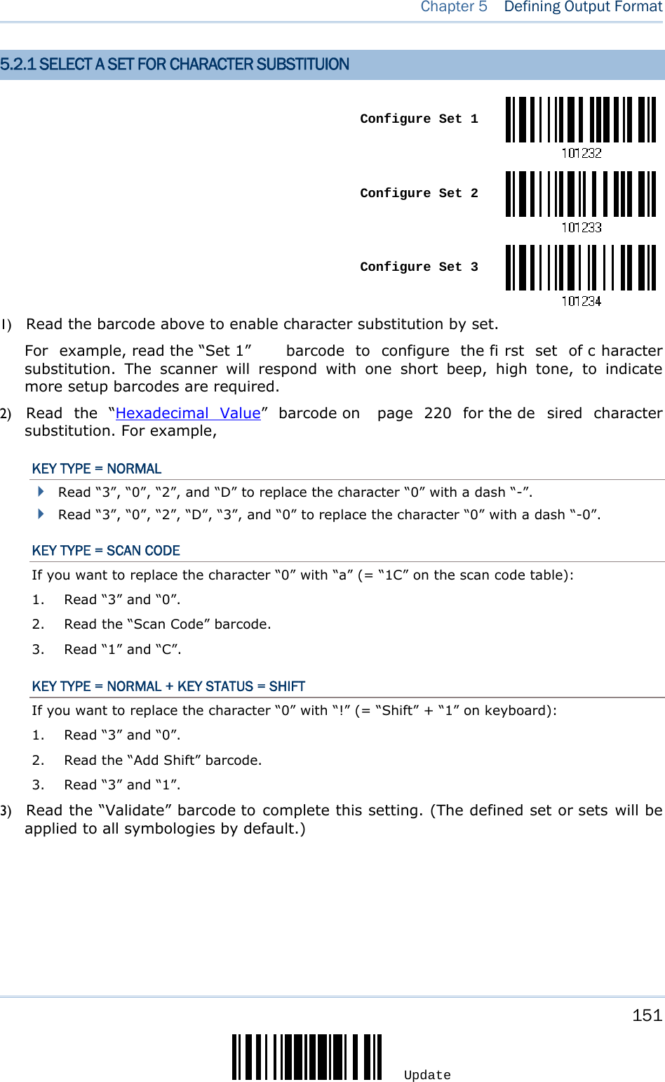
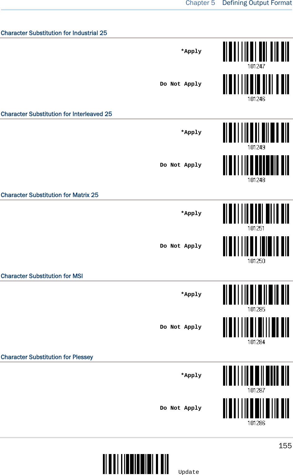
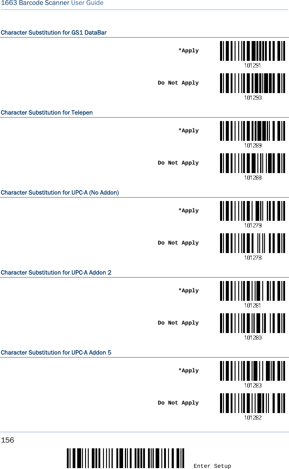
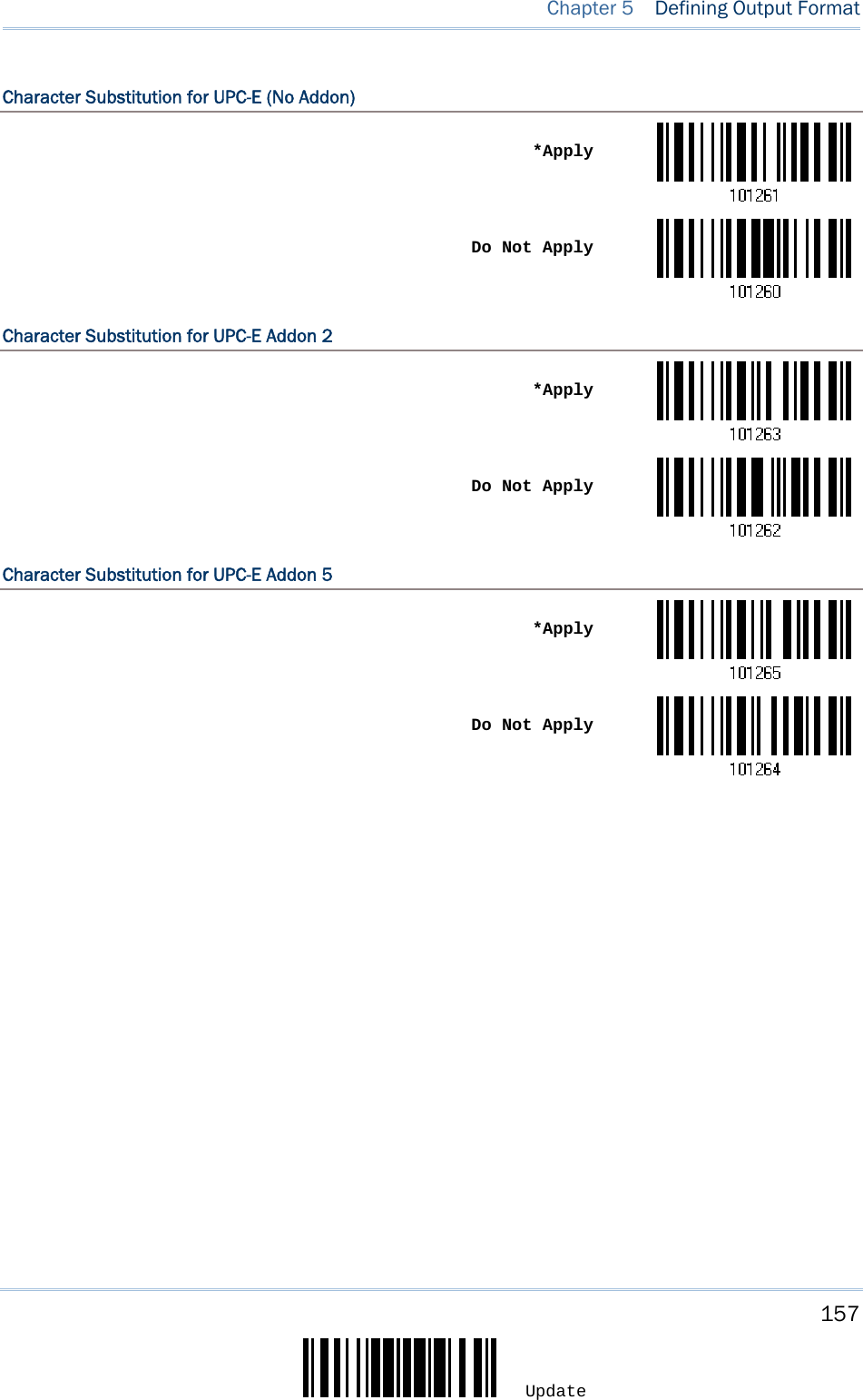
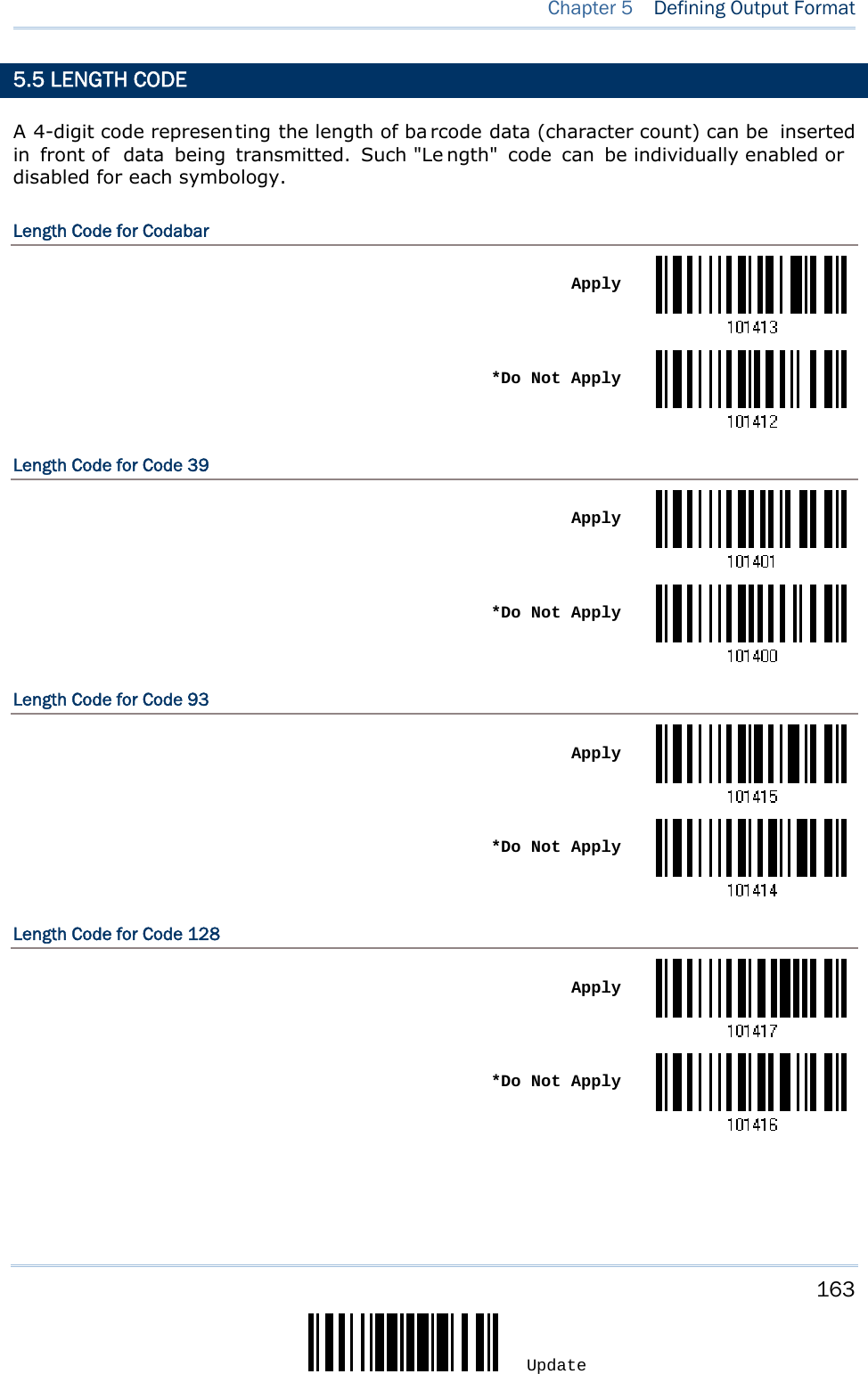
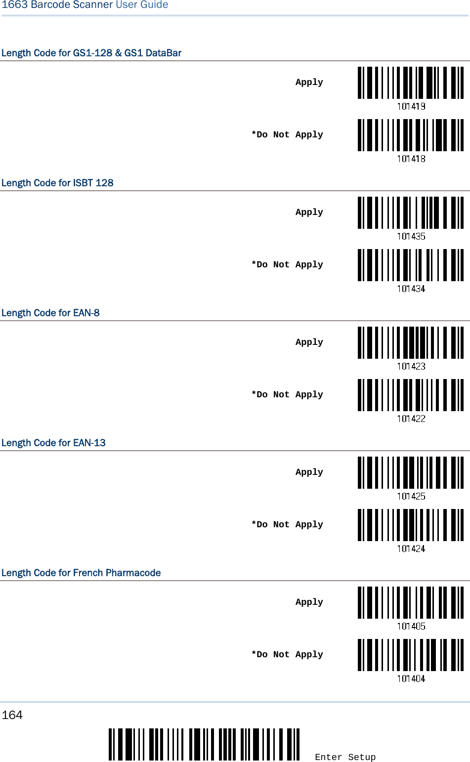
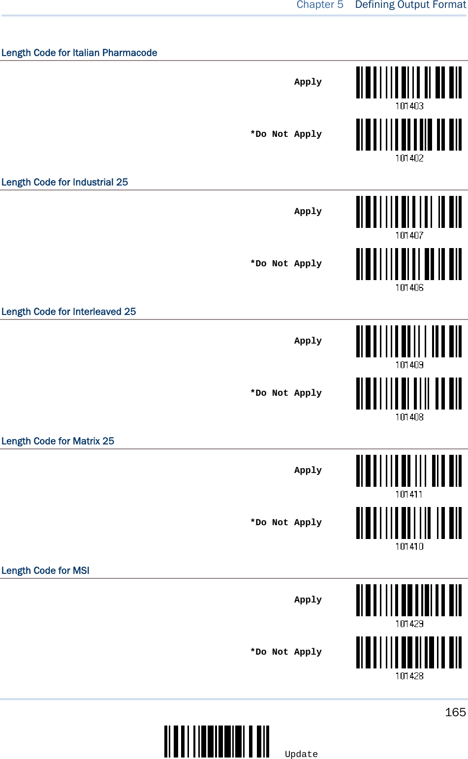
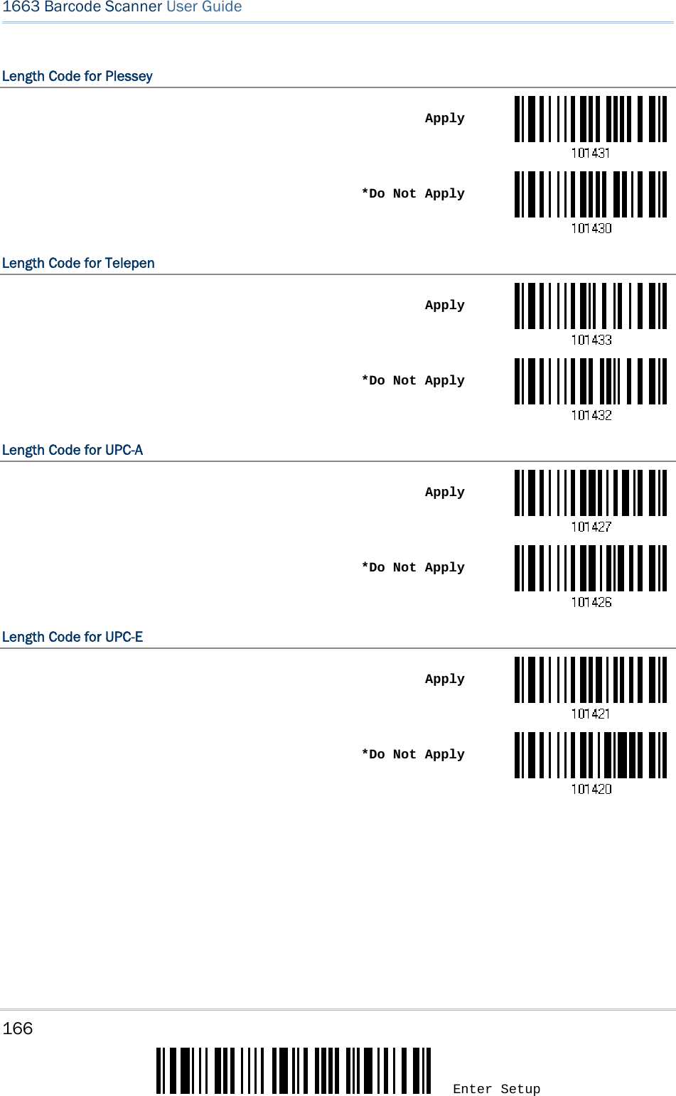
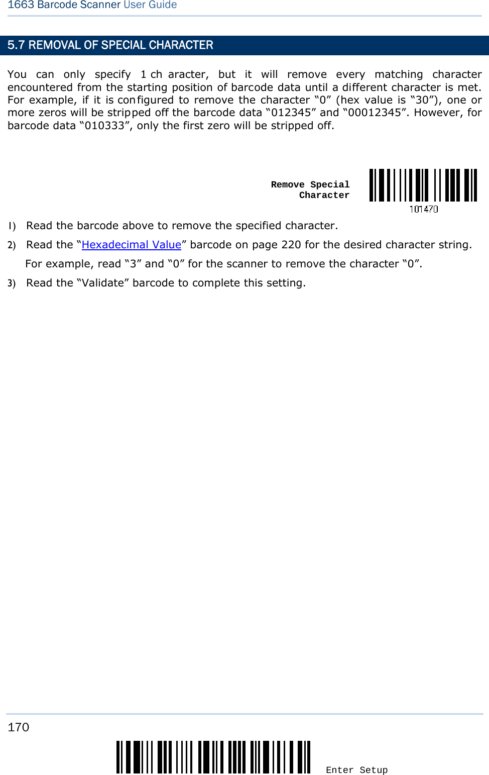
![149 Update You may c onfigure the format of the col lected data outpu t to t he host co mputer. Barcodes read by the scanner will be processed in the following sequence – 1) Perform character substitution on the data scanned. 2) Add Code ID and Length Code to the front of the data:[Code ID][Length Code][Data] 3) Process the whole data in step 2 with user formats. Data is now divided into fields by user specified rules. Refer to Chapter 6 Applying Formats for Data Editing. 4) Add Prefix Code and Suffix Code before transmission: [Prefix Code][Processed Data][Suffix Code] IN THIS CHAPTER 5.1 Letter Case ..............................................................149 5.2 Character Substitution...............................................150 5.3 Prefix/Suffix Code .....................................................158 5.4 Code ID...................................................................159 5.5 Length Code ............................................................163 5.6 Multi-Barcode Editor..................................................167 5.7 Removal of Special Character .....................................170 5.1 LETTER CASE By default, the alphabetics transmission is case-sensitive, meaning that the alphabet will be transmitted according to their original case. Ignoring the original letter case, select [Upper Case] to output data in upper case only; otherwise, select [Lower Case] to output data in lower case only. *Normal Upper Case Lower Case Chapter 5 DEFINING OUTPUT FORMAT](https://usermanual.wiki/CipherLab/1663/User-Guide-1860865-Page-160.png)
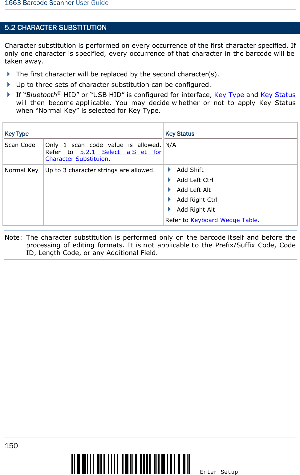
![158 Enter Setup 1663 Barcode Scanner User Guide 5.3 PREFIX/SUFFIX CODE By default, there is no prefix code, and [ENTER] or [CR] (Carriage Return) is configured to be suffix code. Up to 8 characters can be configured, for example, “Barcode_”, and you will have the string appear in front of the barcode read, like this – “Barcode_1234567890”. If “Bluetooth® HID” or “USB HID” is configured for interface, Key Type and Key Status will then become appl icable. You may decide w hether or not to apply Key Status when “Normal Key” is selected for Key Type. Key Type Key Status Scan Code Up to 4 scan code values are allowed. N/A Normal Key Up to 8 character strings are allowed. Add Shift Add Left Ctrl Add Left Alt Add Right Ctrl Add Right Alt Refer to Keyboard Wedge Table. Configure Prefix Configure Suffix1) Read the barcode above to apply prefix co de or suffix code separately, and follow steps 2~3. (Max. 8 characters each) 2) Read the “Hexadecimal Value” barcode on pa ge 220 for the desired character string. For example, read “2” and “B” for the scanner to prefix or suffix the character [+]. 3) Read the “Validate” barcode to complete this setting.](https://usermanual.wiki/CipherLab/1663/User-Guide-1860865-Page-169.png)
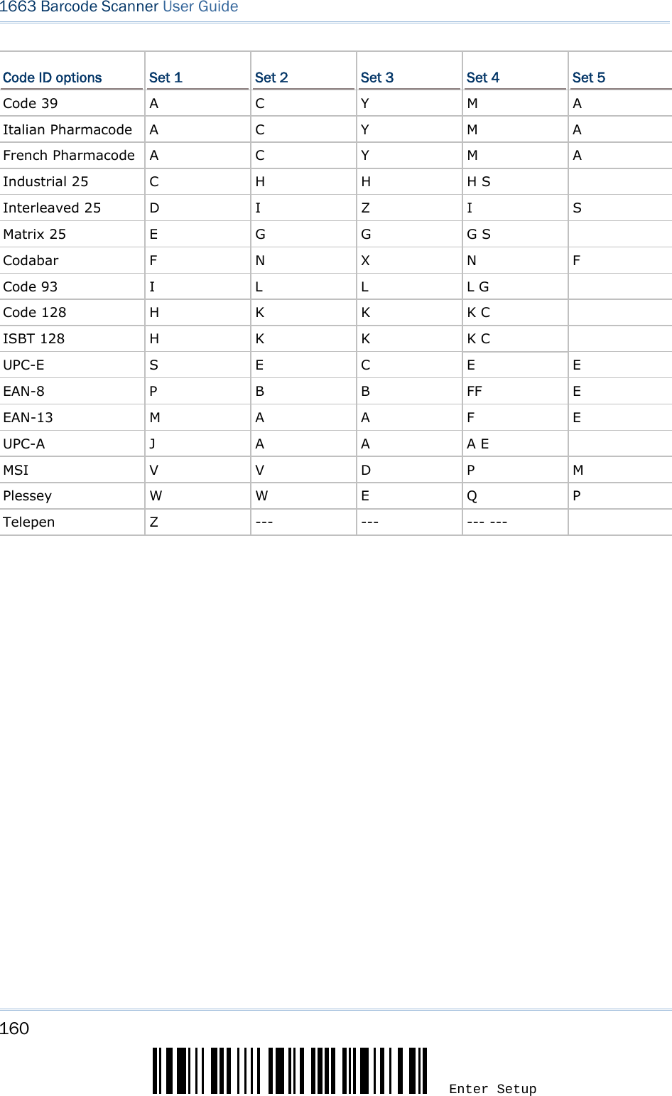
![159 Update Chapter 5 Defining Output Format 5.4 CODE ID Up to two characters for Code ID can be configured for each symbology. To make the Code ID configuration easier, the scanner provides five pre-defined Code ID sets that you can select one and make necessary changes on it. If “Bluetooth® HID” or “USB HID” is configured for interface, Key Type and Key Status will then become appl icable. You may decide w hether or not to apply Key Status when “Normal Key” is selected for Key Type. Key Type Key Status Scan Code Only 1 scan code value is allowed. N/A Normal Key Up to 2 character strings are allowed. Add Shift Add Left Ctrl Add Left Alt Add Right Ctrl Add Right Alt Refer to Keyboard Wedge Table. Note: "]C1" is the Code ID of GS1-128 (EAN-128) barcodes; "]e0" is the default Code ID of GS1 DataBar (RSS) barcodes. 5.4.1 SELECT PRE-DEFINED CODE ID Apply Code ID Set 1 Apply Code ID Set 2 Apply Code ID Set 3 Apply Code ID Set 4 Apply Code ID Set 5](https://usermanual.wiki/CipherLab/1663/User-Guide-1860865-Page-170.png)
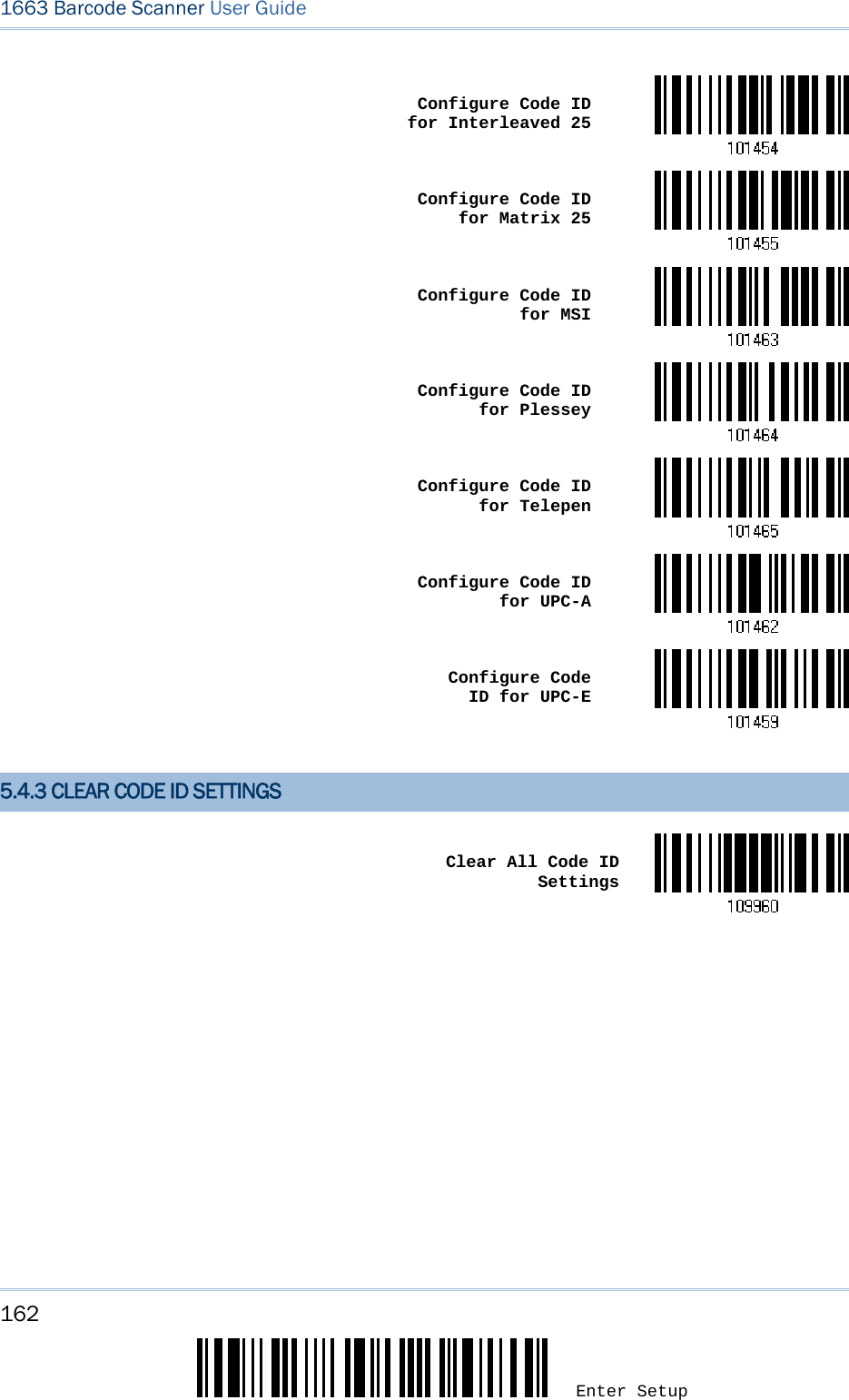
![161 Update Chapter 5 Defining Output Format 5.4.2 CHANGE CODE ID 1) Read the barcode below to change code ID of a specific symbology. 2) Read the “Hexadecimal Value” barcode on pa ge 220 for the desired character string. For example, read “4” and “4” for applying the character [D] for Code ID. 3) Read the “Validate” barcode to complete this setting. Configure Code ID for Codabar Configure Code ID for Code 39 Configure Code ID for Code 93 Configure Code ID for Code 128 Configure Code ID for ISBT 128 Configure Code ID for EAN-8 Configure Code ID for EAN-13 Configure Code ID for French Pharmacode Configure Code ID for Italian Pharmacode Configure Code ID for Industrial 25](https://usermanual.wiki/CipherLab/1663/User-Guide-1860865-Page-172.png)
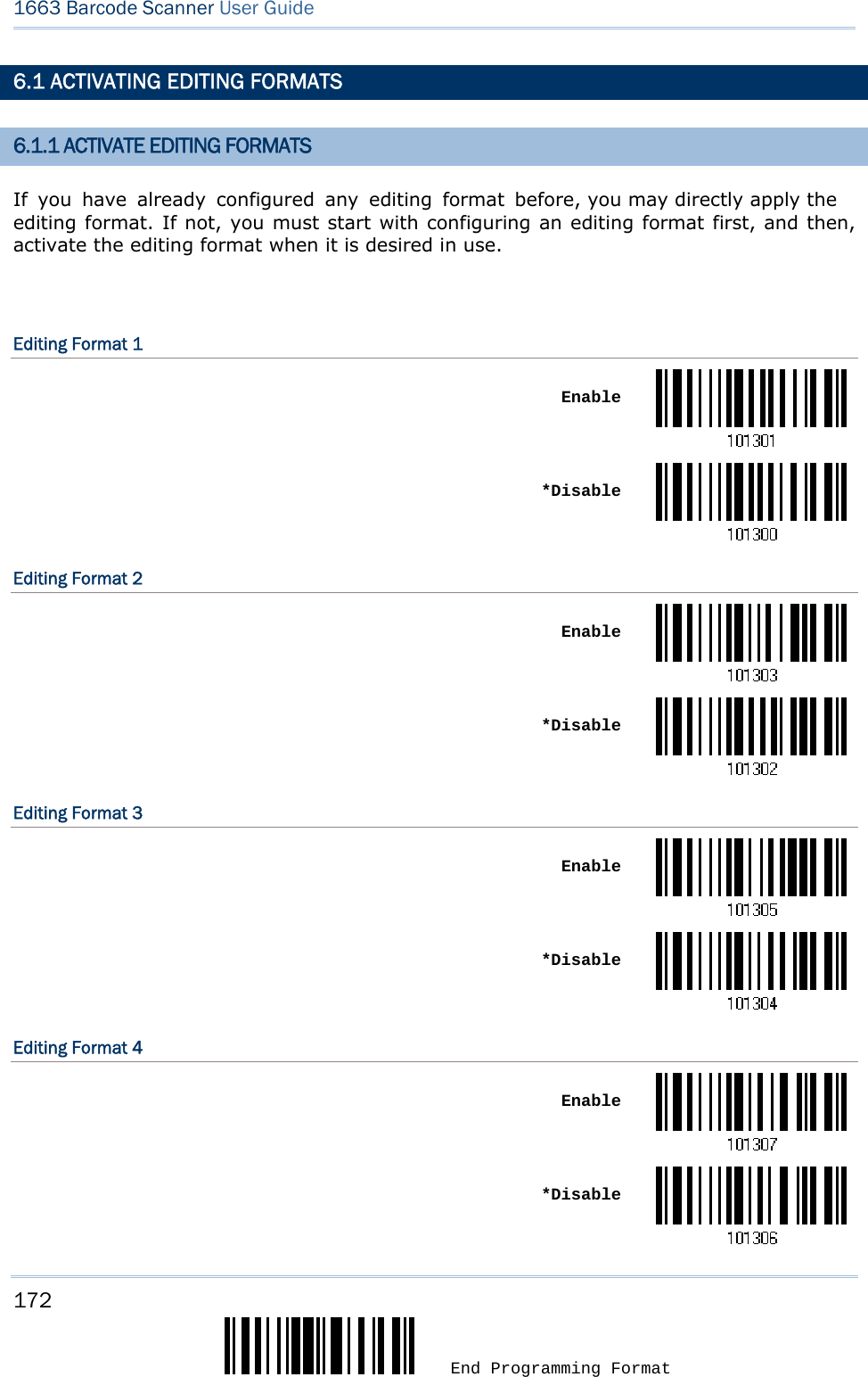
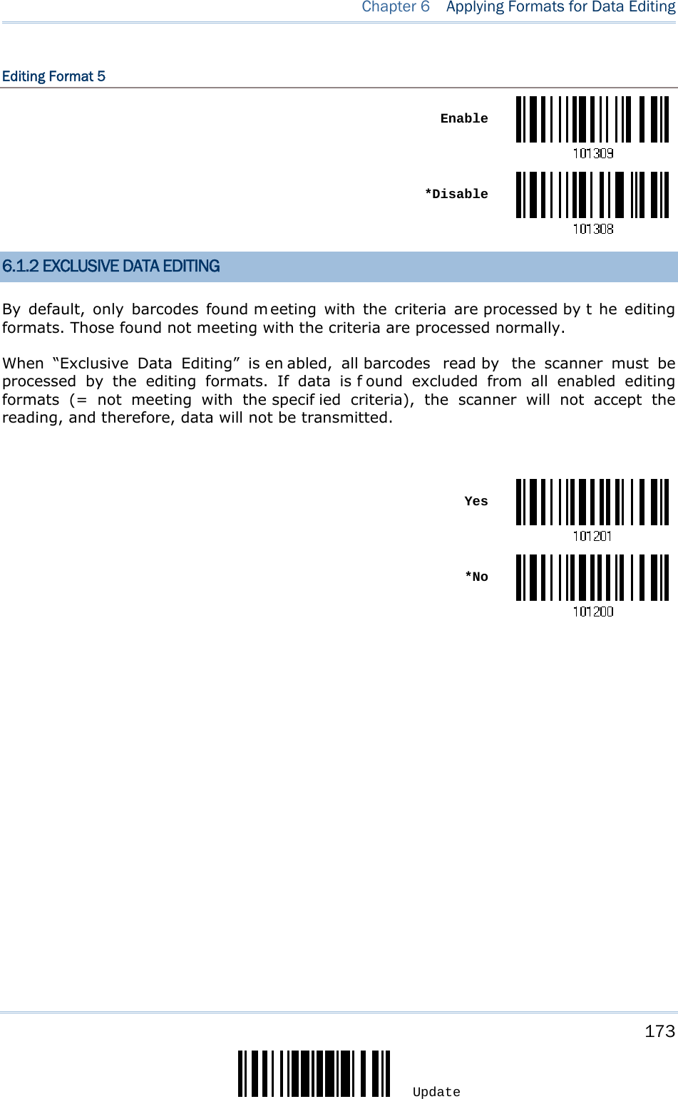
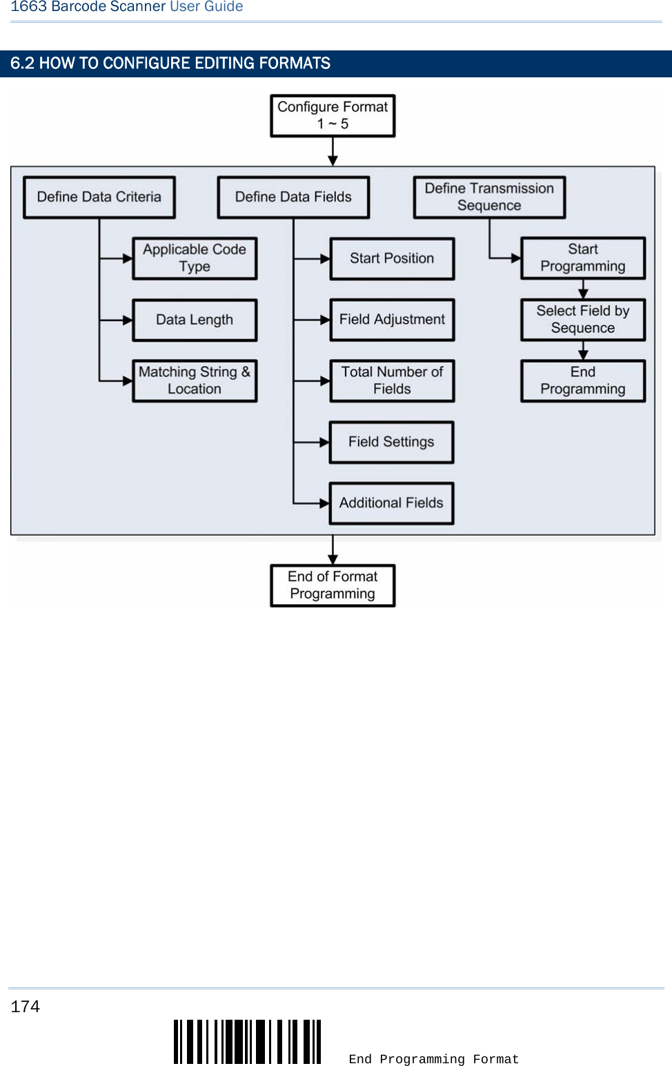
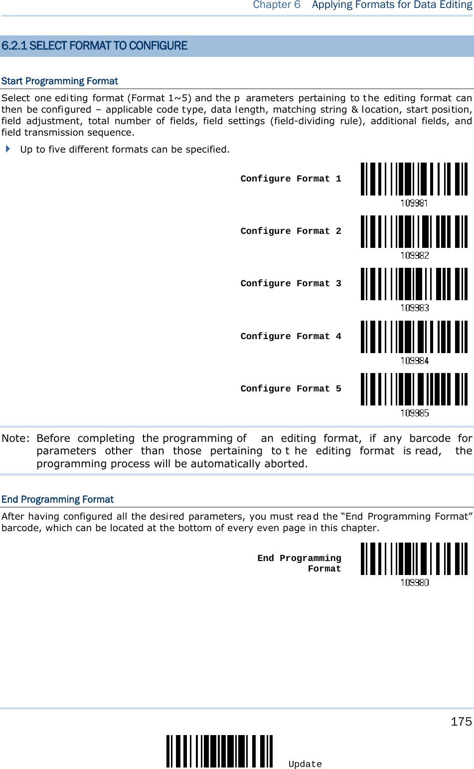
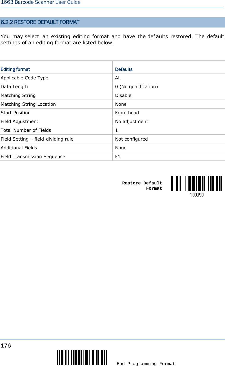
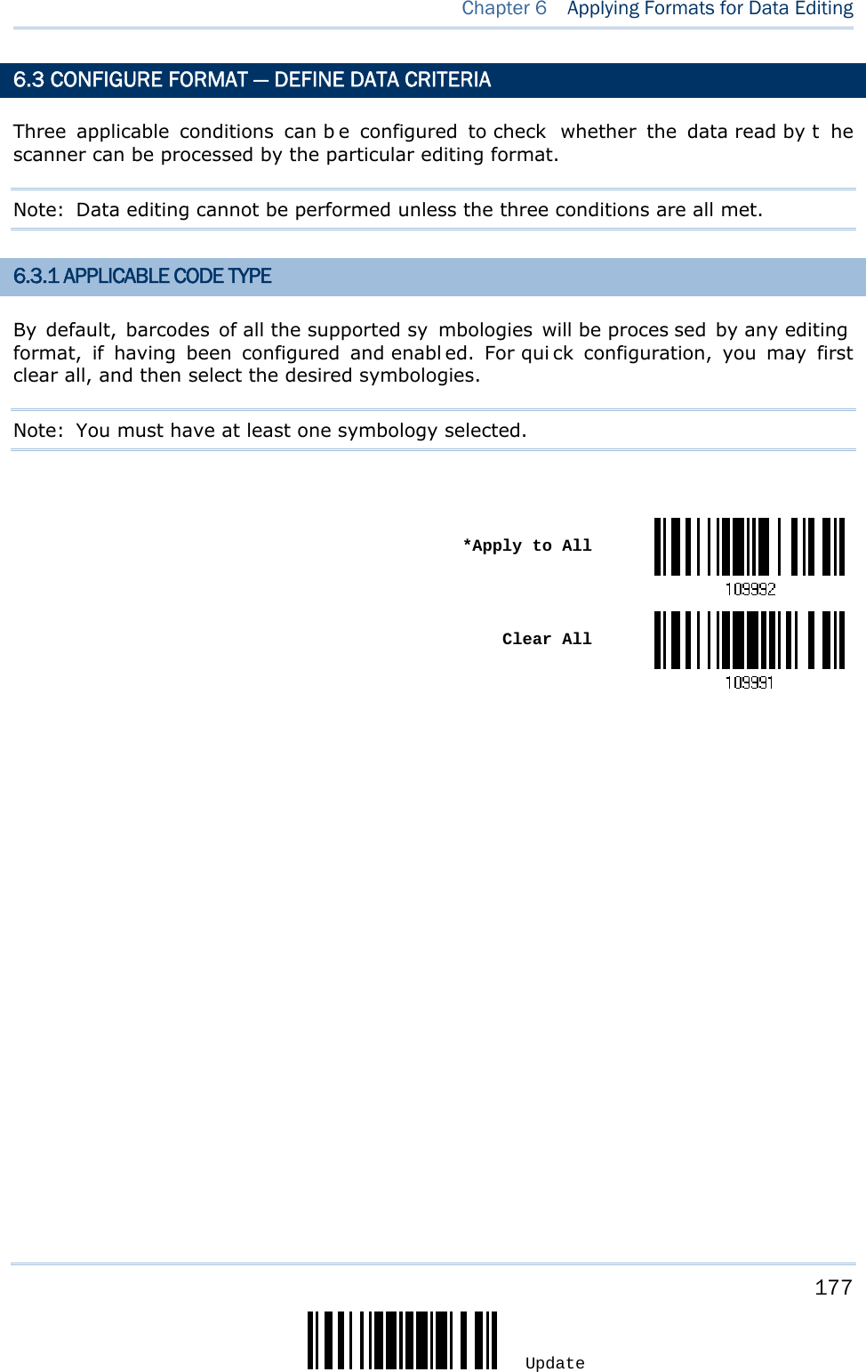
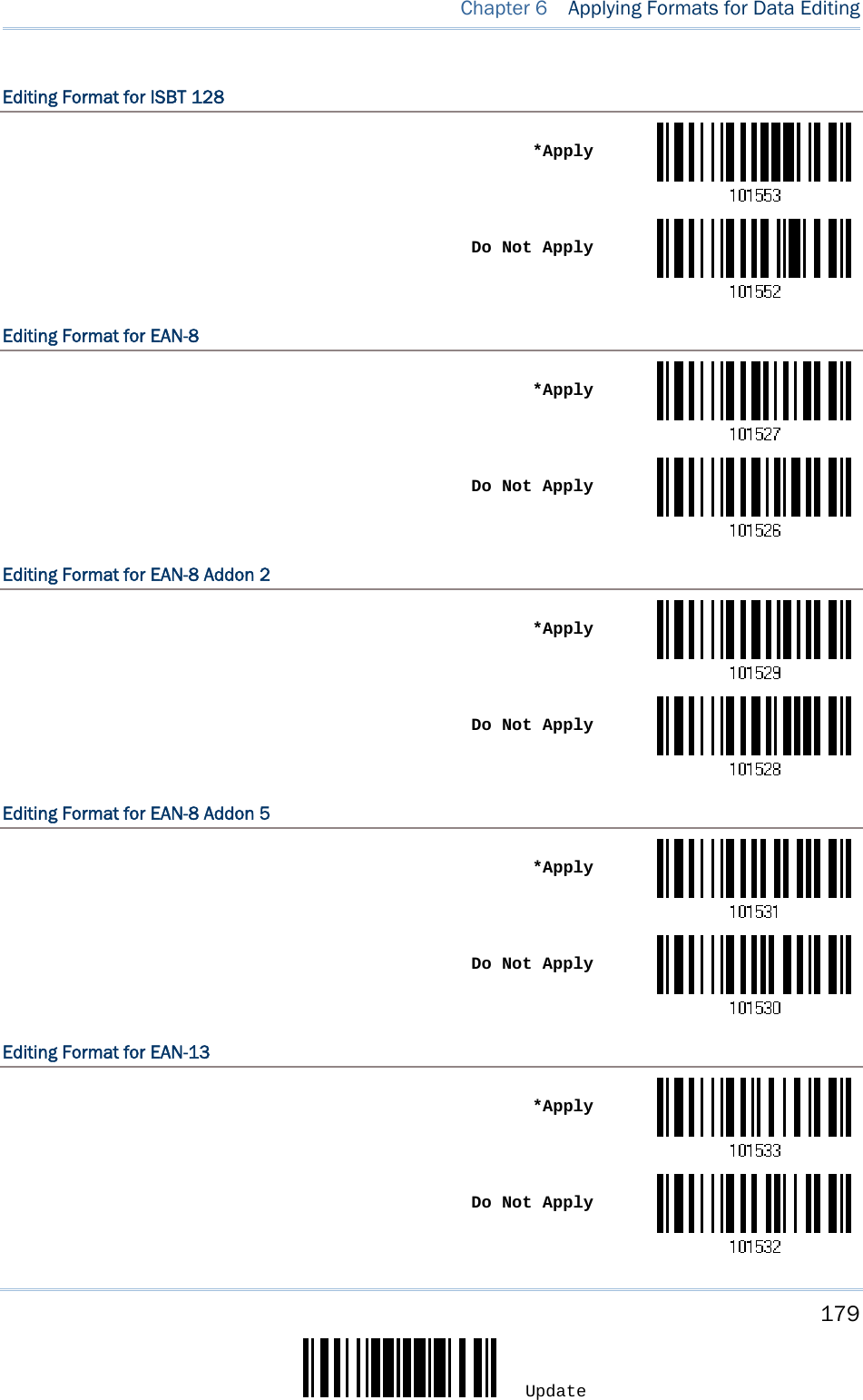
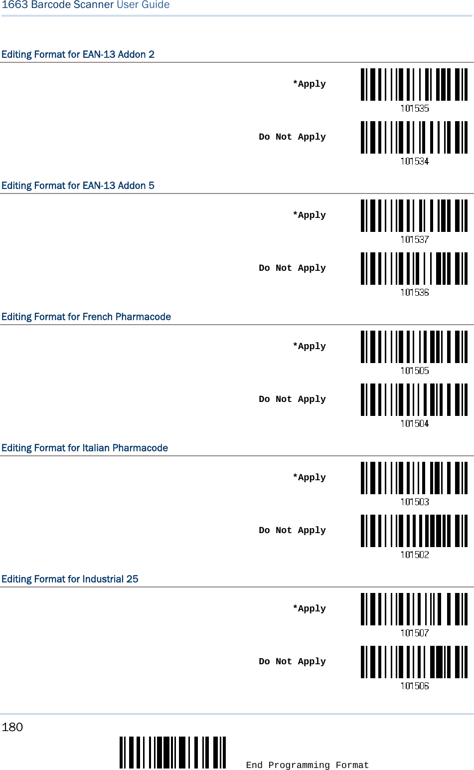
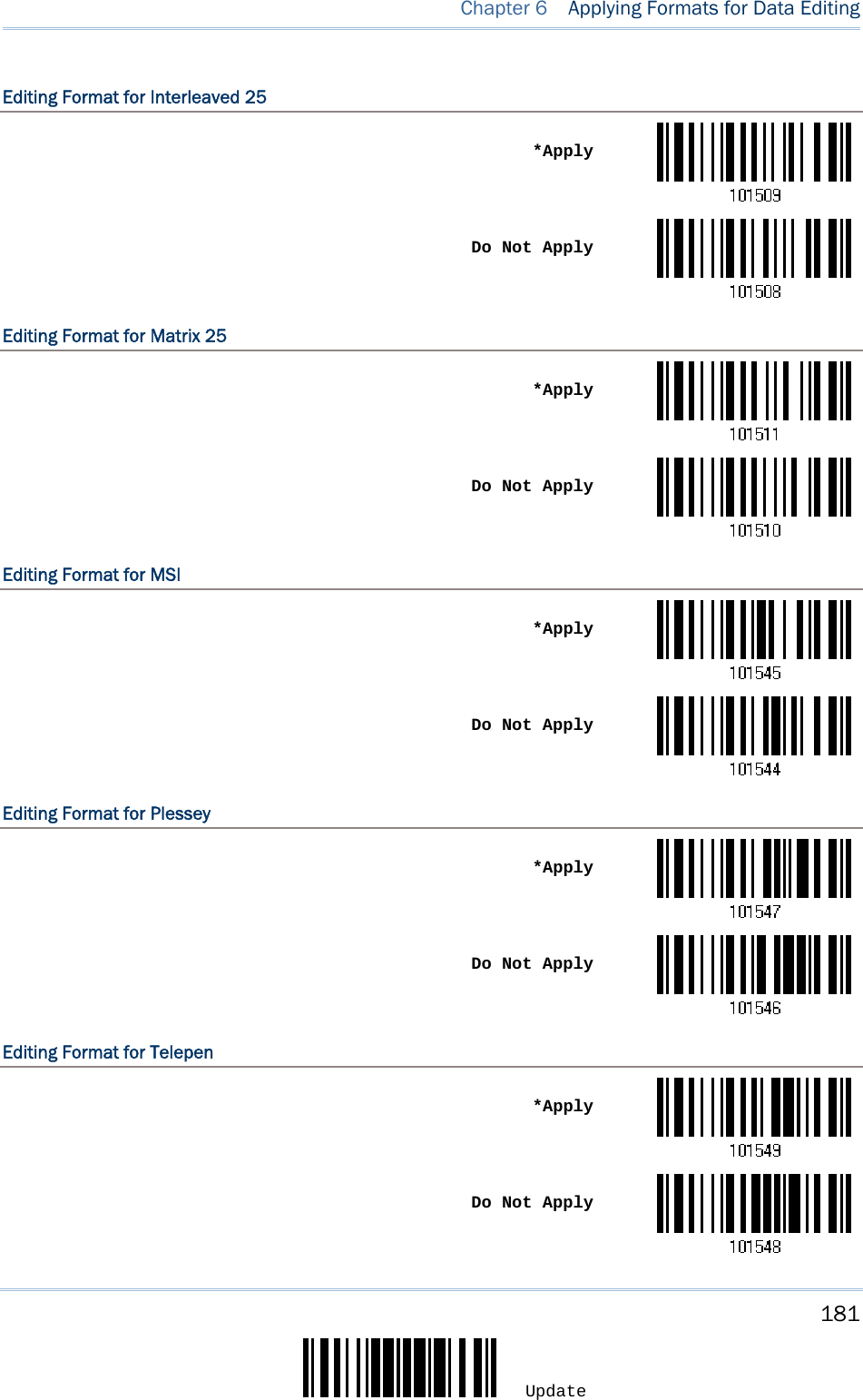
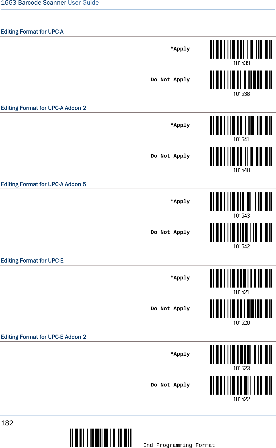
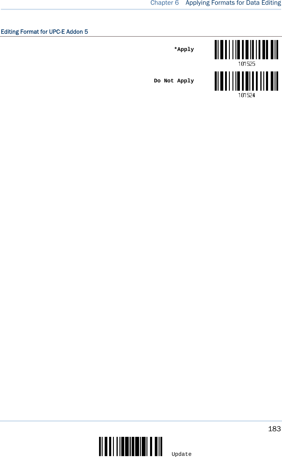
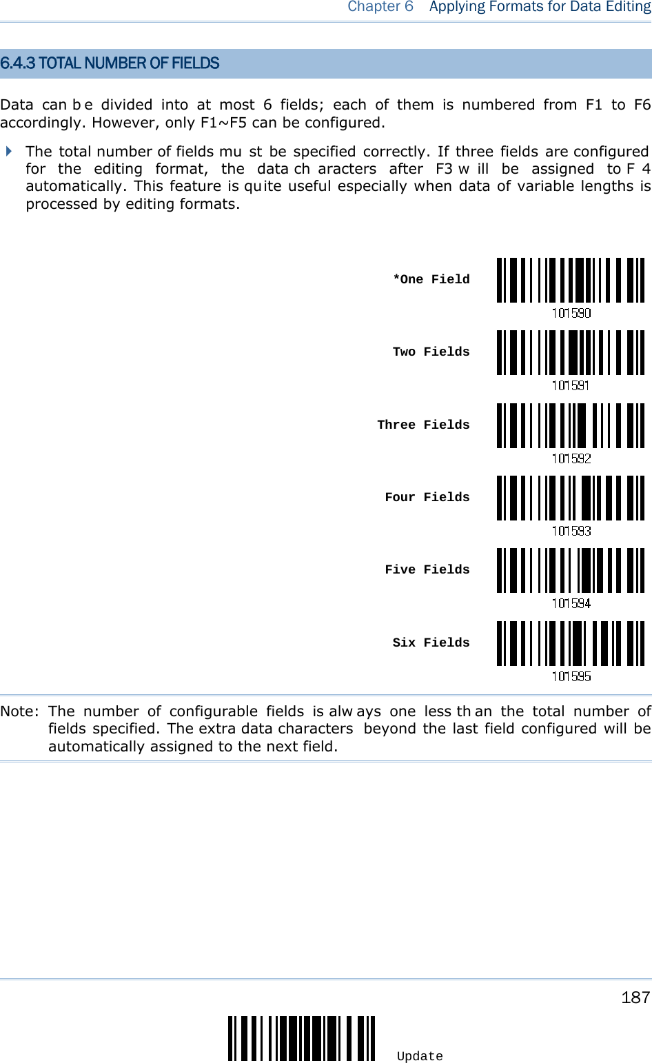
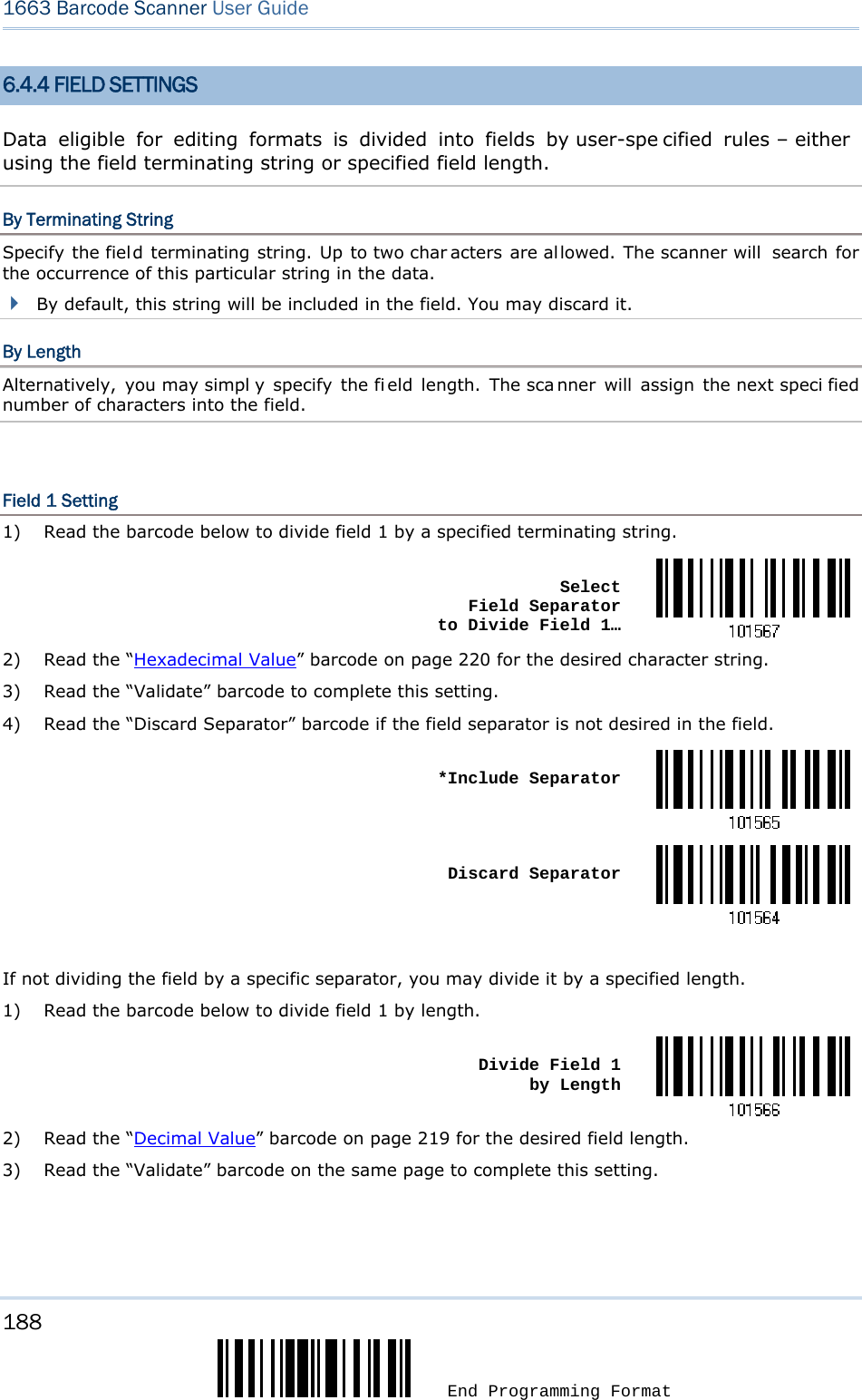
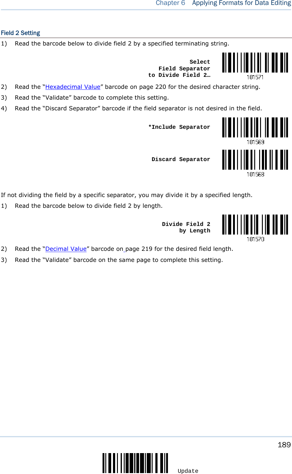
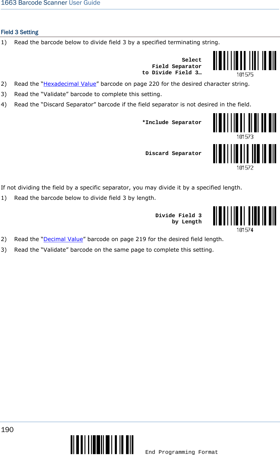
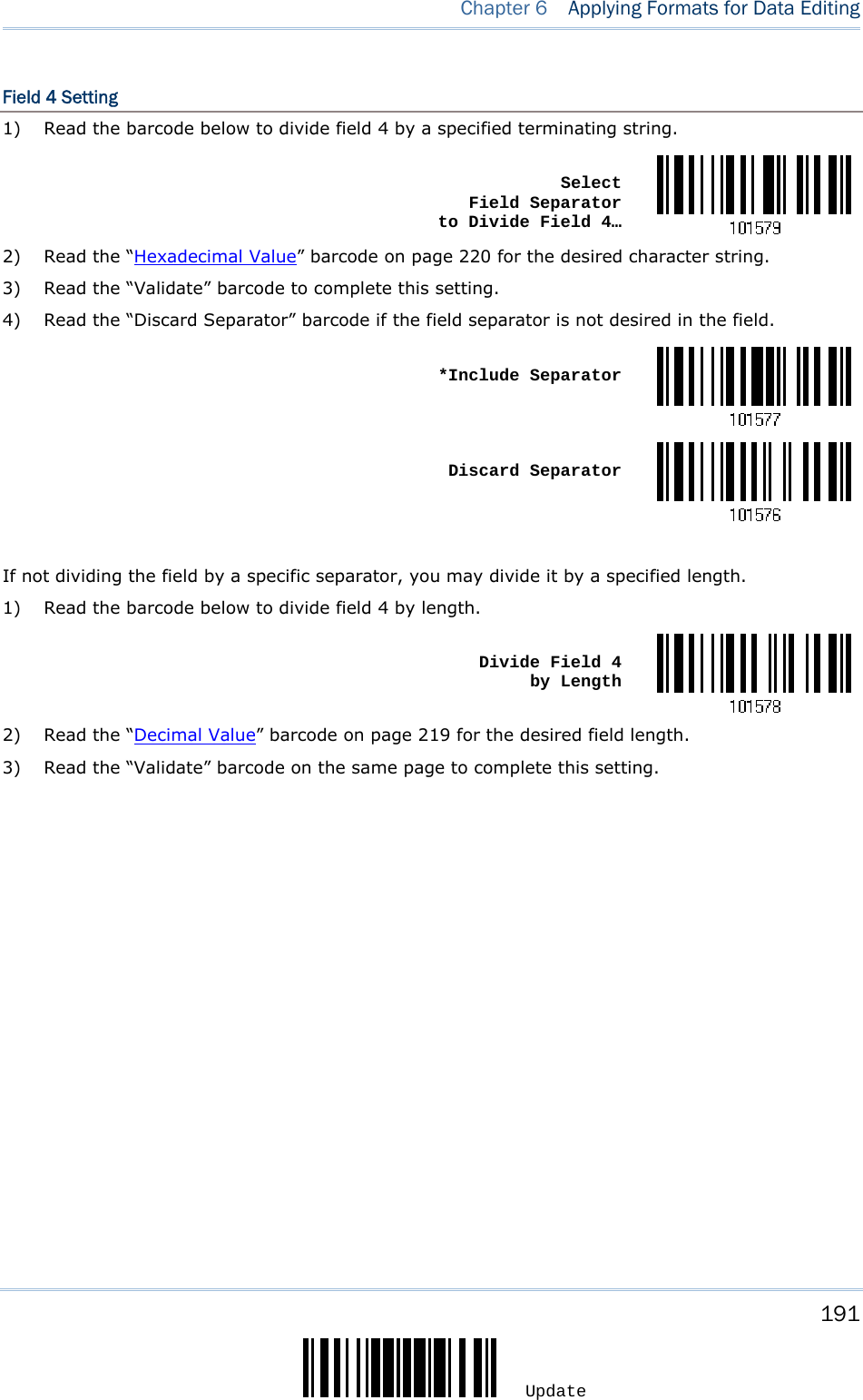
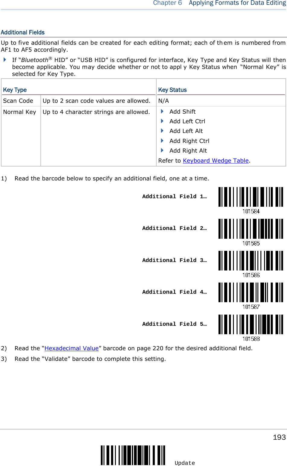
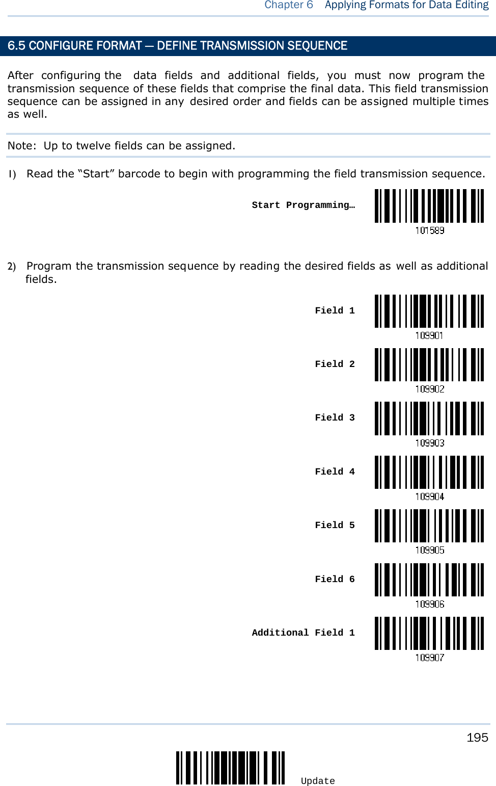
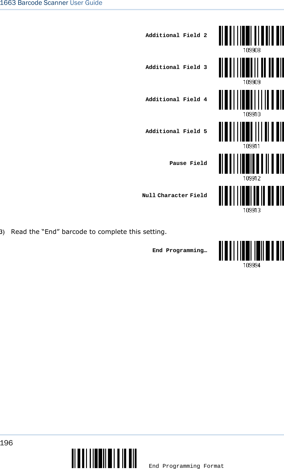
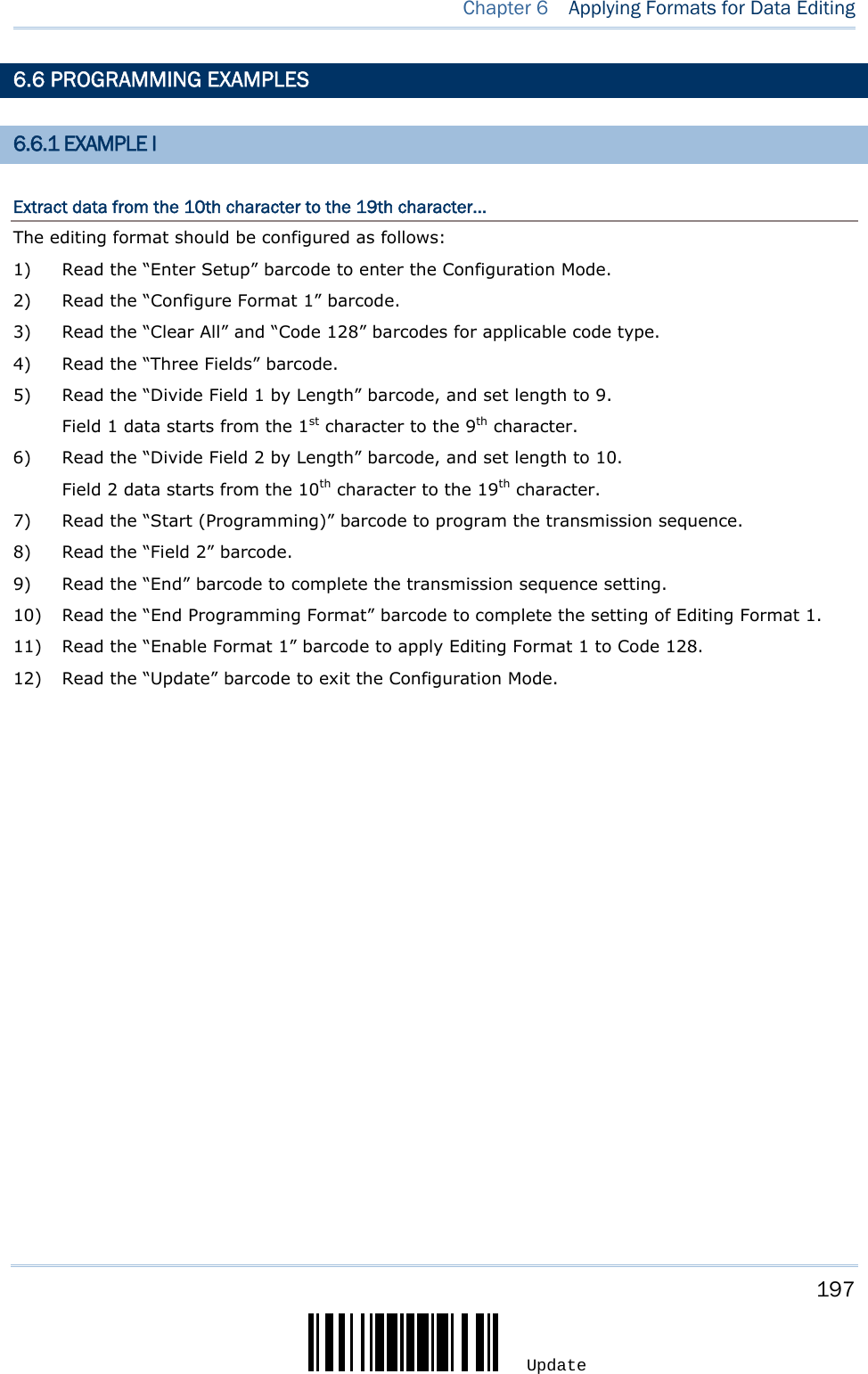
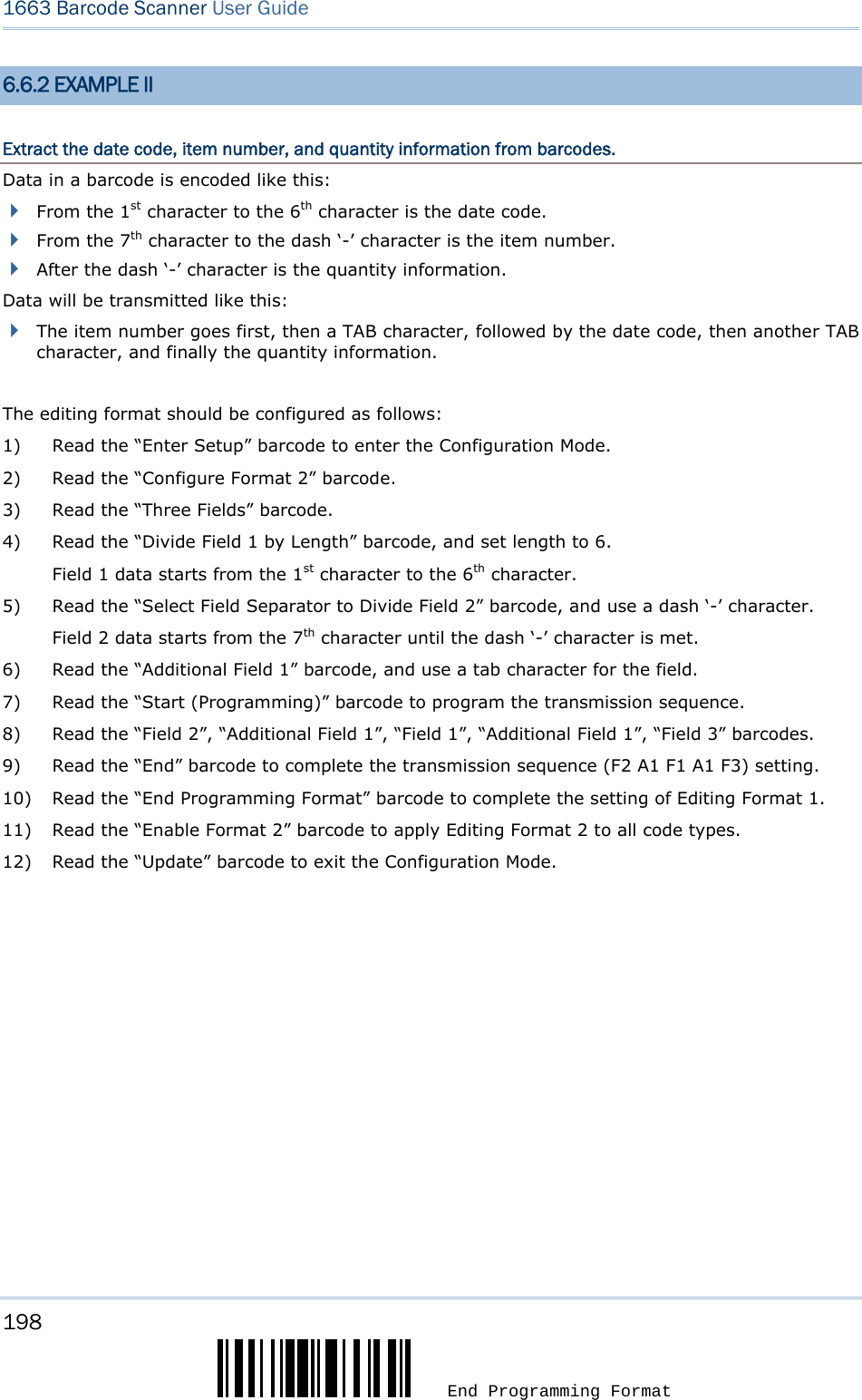
![171 Update The scanner allows advanced data editing by applying user-configured editing formats. The whole processed data can b e divided into fields by user -specified rules. The data actually sent to the host computer comprises those fields together with the user-configurable additional fields. [Time Stamp] [Prefix Code] [Code ID] [Length Code] [Data] Additional Field(s) [Time Stamp] [Suffix Code] None by default None by default None by default None by default Barcode itself None by default None by default 0x0d by default IN THIS CHAPTER 6.1 Activating Editing Formats..........................................172 6.2 How to Configure Editing Formats ...............................174 6.3 Configure Format — Define Data Criteria......................177 6.4 Configure Format — Define Data Field .........................186 6.5 Configure Format — Define Transmission Sequence .......195 6.6 Programming Examples .............................................197 Chapter 6 APPLYING FORMATS FOR DATA EDITING](https://usermanual.wiki/CipherLab/1663/User-Guide-1860865-Page-182.png)


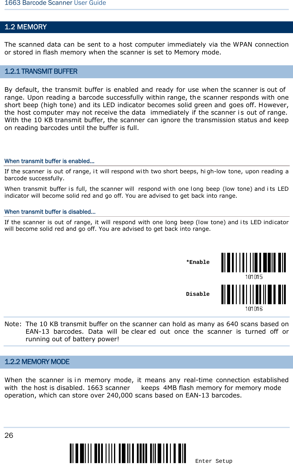
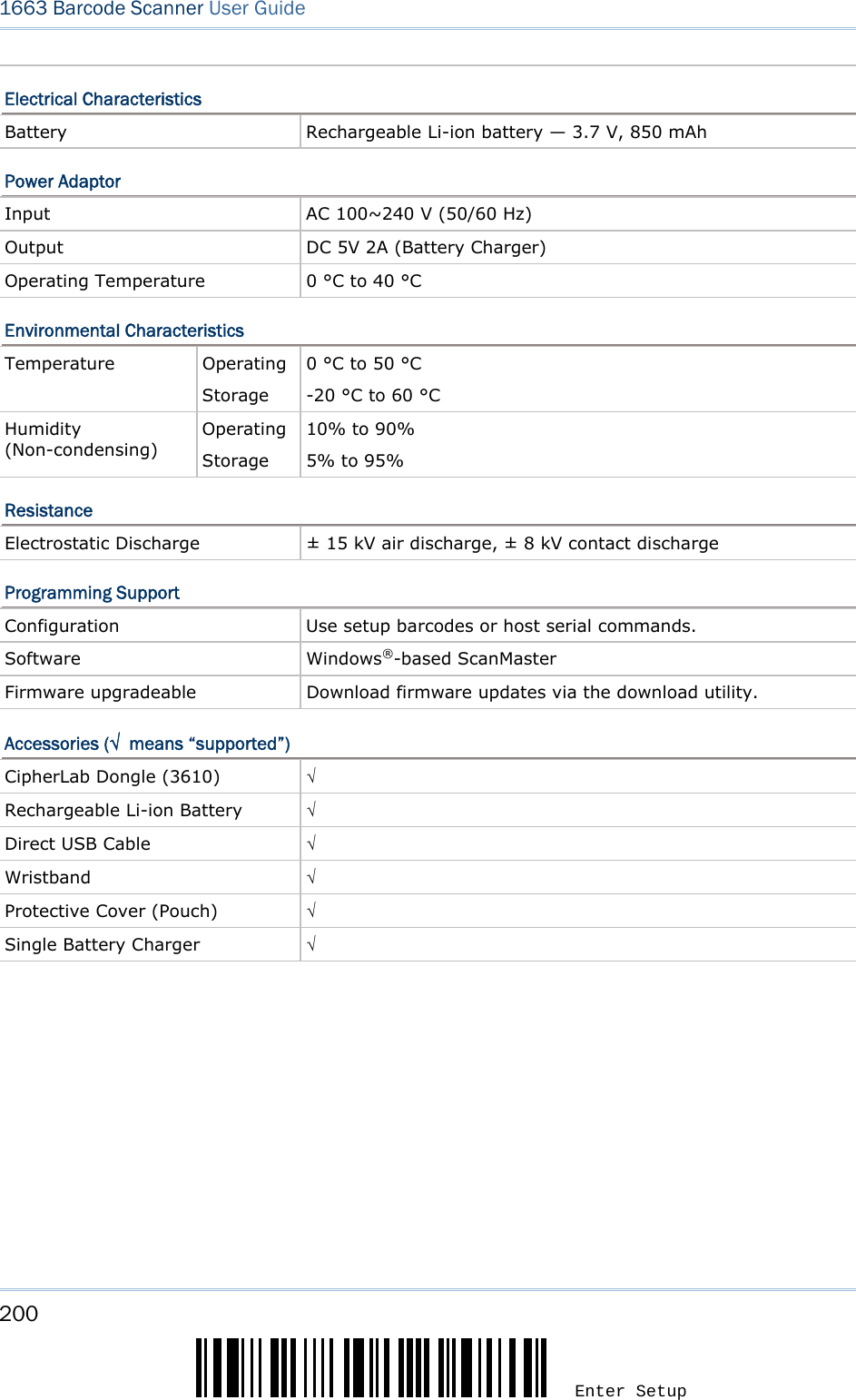
![199 Update Optical Characteristics 1663 Optical Sensor 2500 pixels CCD image sensor Light Source Visible Red LED RF Characteristics WPAN Module Bluetooth® Class 3, Version 2.1 Coverage (line-of-sight) 20 meters with 3610 Interface Supported Serial Port Profile (Bluetooth® SPP) Human Interface Device Profile (Bluetooth® HID) 3610 Direct USB HID Direct USB Virtual COM Physical Characteristics Memory 10 KB for transmit buffer 4MB flash for memory mode Switch Push-button switch for [Trigger] key, plus [Power/Delete] key Indication Triple-color LED (Red/Green/Blue) and beeper Dimensions 113 x 44.9 x 29.9 mm Weight 106g (With Battery) 83g (Without Battery) SPECIFICATIONS](https://usermanual.wiki/CipherLab/1663/User-Guide-1860865-Page-210.png)
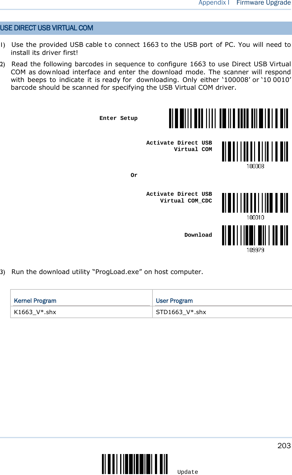
![202 Enter Setup 1663 Barcode Scanner User Guide 4) Read the following barcodes in sequence for the scanner to enter the download mode. The scanner will respond with beeps to indicate it is ready for downloading. Enter SetupDownload 5) Run the download utility “ProgLoad.exe” on your computer. Kernel Program User Program K1663_V*.shx STD1663_V*.shx For the co mmunication settings, select “RS-232” and the correct COM port for US B Virtual COM interface. Ignore the baud rate setting. For the fil e option, click [Browse] to sel ect the target file for firmware update. Click [OK]. 6) After upgrading kernel, you will need to manually restart the scanner. After upgrading the user program, the scanner will automatically restart itself once the download is completed successfully. Note: The output interface remains unchanged as specified in step 3 (= USB Virt ual COM).](https://usermanual.wiki/CipherLab/1663/User-Guide-1860865-Page-213.png)
![204 Enter Setup 1663 Barcode Scanner User Guide For the co mmunication settings, select “RS-232” and the corr ect COM por t for Direct USB Virtual COM interface. Ignore the baud rate setting. For the fil e option, click [Browse] to sel ect the target file for firmware update. Click [OK]. 4) After upgrading kernel, you will need to restart the scanner manually. After upgrading the user program, the scanner will restart itself automatically once the download is completely. Note: Because 1663 supports the downloading of firmware via Direct USB Virtual COM interface, the output interface will be set to the previously used one upon completion of firmware upgrade. USE BLUETOOTH® DONGLE 1) Refer to 3.2.3 Connect to Do ngle for the target scanner to accept the connection request from your computer. 2) Read the following barcodes in sequence to configure the scanner to use Bluetooth® SPP as download interface. Enter Setup Activate Bluetooth® SPP Update](https://usermanual.wiki/CipherLab/1663/User-Guide-1860865-Page-215.png)
![205 Update Appendix I Firmware Upgrade 3) Read the following barcodes in sequence for the scanner to enter the download mode. The scanner will respond with beeps to indicate it is ready for downloading. Enter Setup Download 4) Run the download utility “ProgLoad.exe” on your computer. Kernel Program User Program K1663_V*.shx STD1663_V*.shx For the co mmunication settings, select “RS-232” and the corr ect COM por t for Bluetooth® SPP interface. Ignore the baud rate setting. For the fil e option, click [Browse] to sel ect the target file for firmware update. Click [OK]. 5) After upgrading kernel, you will need to manually restart the scanner. After upgrading the user program, the scanner will automatically restart itself once the download is completed successfully. Note: The output interface remains unchanged as specified in step 2 (=Bluetooth® SPP).](https://usermanual.wiki/CipherLab/1663/User-Guide-1860865-Page-216.png)
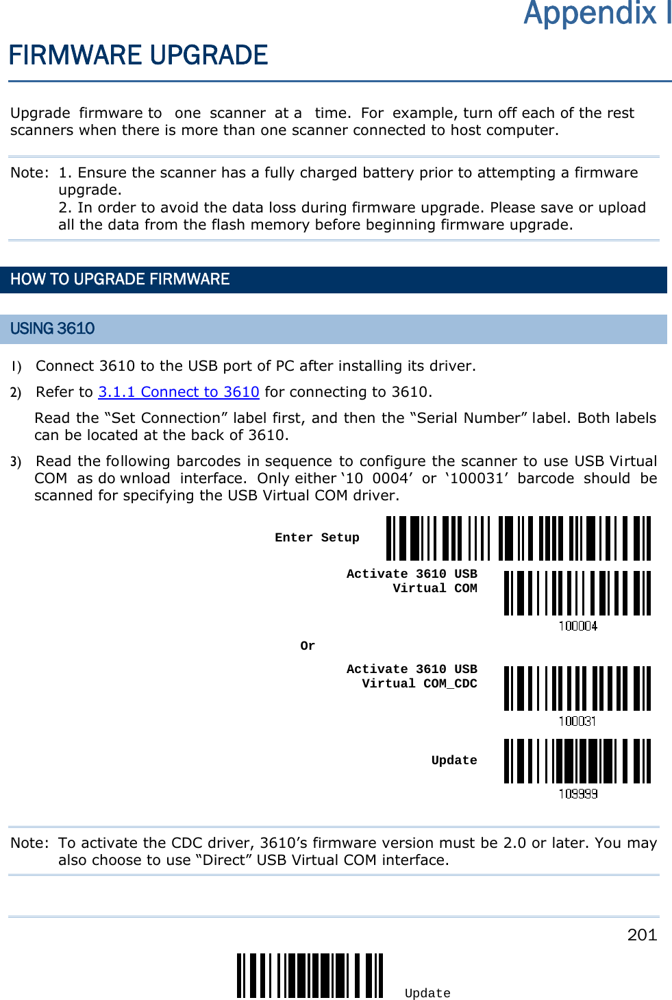
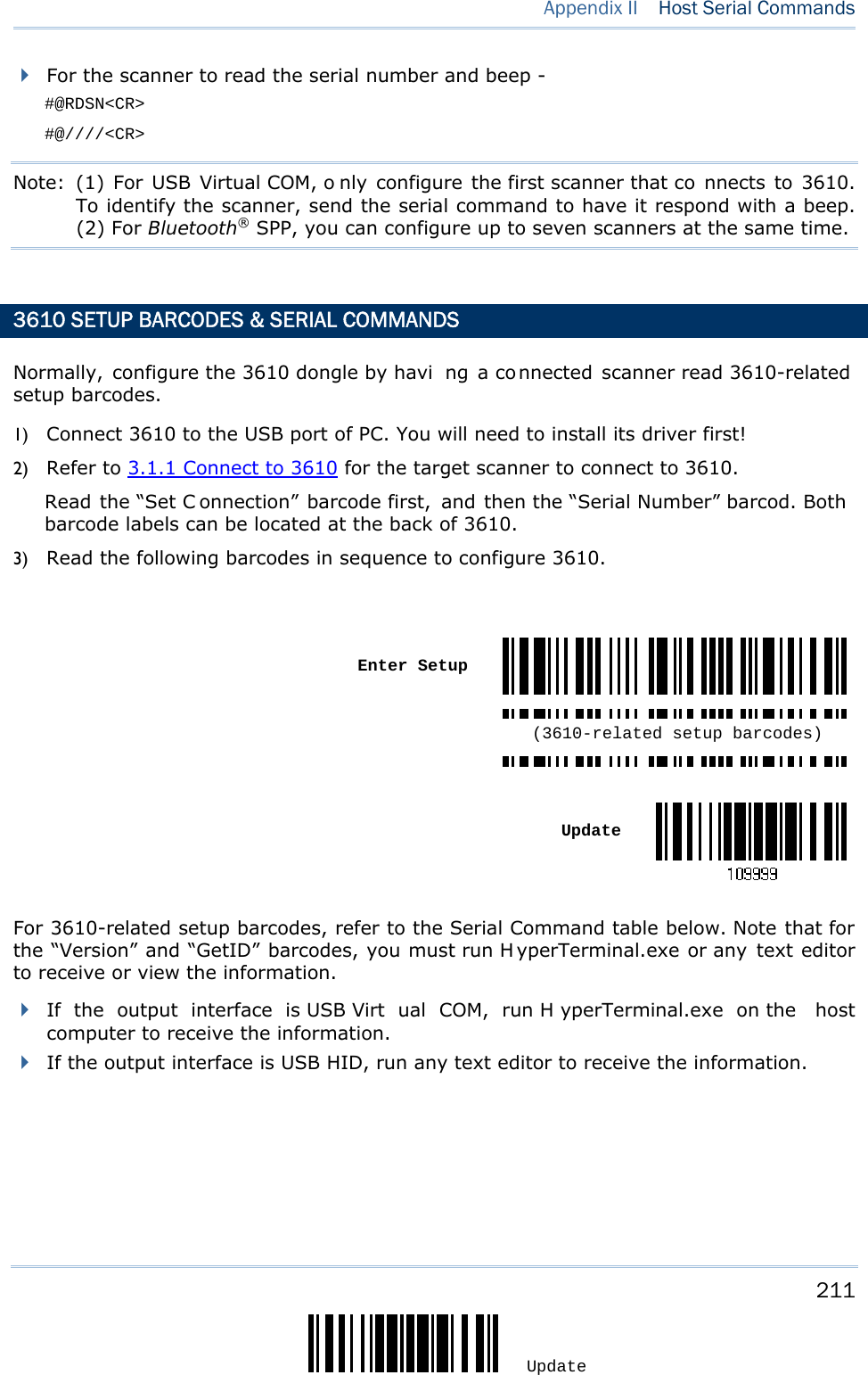
![206 Enter Setup 1663 Barcode Scanner User Guide HOW TO UPGRADE 3610 FIRMWARE Connect 3610 to the USB port of PC after installing its driver. Refer to 3.1.1 Connect to 3610 for the target scanner to connect to 3610. UPGRADE 3610 CPU FIRMWARE 1) Read the following barcodes in sequence for 3610 to enter the download mode. The Communication LED on 3610 w ill be f lashing red to indicate it is rea dy for downloading. Enter Setup Download 3610 CPU Firmware 2) Run the download utility “ProgLoad.exe” on your computer. Kernel Program User Program K3610_V*.shx STD3610_V*.shx For the co mmunication settings, select “RS-232” and the correct COM port for US B Virtual COM interface. Ignore the baud rate setting. For the fil e option, click [Browse] to sel ect the target file for firmware update. Click [OK]. 3) The 3610 will automatically restart itself when upgrading firmware is completed successfully.](https://usermanual.wiki/CipherLab/1663/User-Guide-1860865-Page-217.png)
![207 Update Appendix I Firmware Upgrade 4) Read the “Update” b arcode for the scan ner to resume i ts operation (exit the configuration mode). Update UPGRADE 3610 USB BRIDGE FIRMWARE 1) Read the following barcodes in sequence for 3610 to enter the download mode. The Communication LED on 3610 w ill be f lashing red to indicate it is rea dy for downloading. Enter Setup Download 3610 USB Bridge Firmware 2) Run the download utility “ProgLoad.exe” on your computer. Kernel Program User Program K3610Bridge_V*.shx STD3610Bridge_V*.shx For the co mmunication settings, select “RS-232” and the correct COM port for US B Virtual COM interface. Ignore the baud rate setting. For the fil e option, click [Browse] to sel ect the target file for firmware update. Click [OK].](https://usermanual.wiki/CipherLab/1663/User-Guide-1860865-Page-218.png)
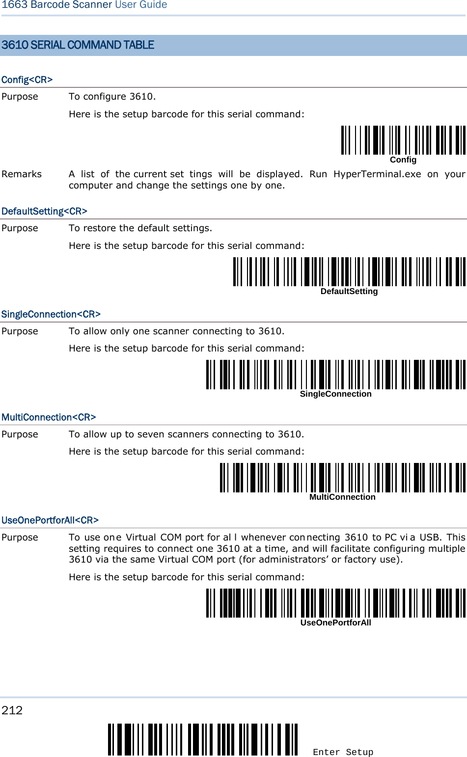
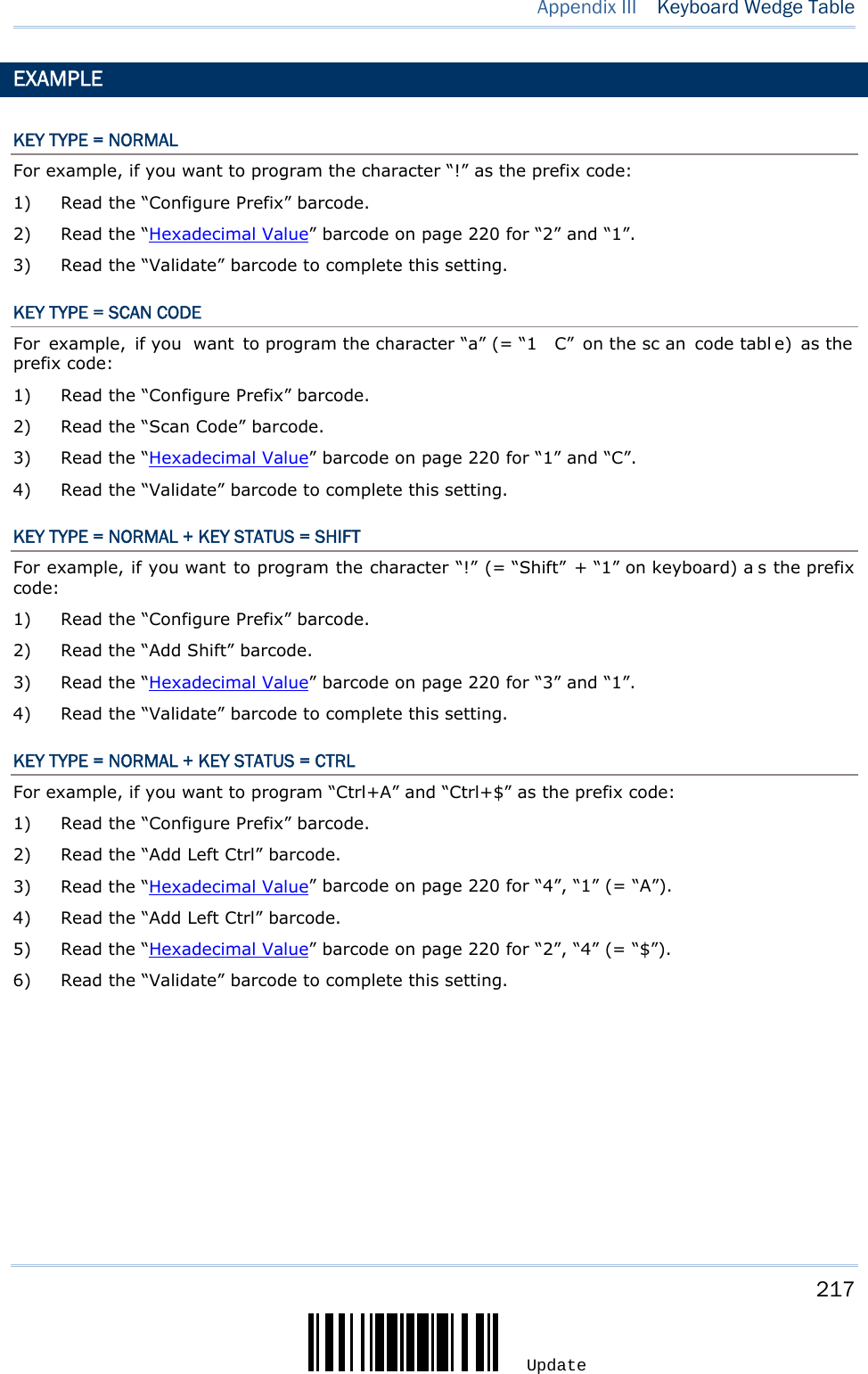
![214 Enter Setup 1663 Barcode Scanner User Guide EXAMPLE Without using the sca nner to read the abov e setup barcodes for configuring the 3610 dongle, run HyperTerminal.exe on the host computer to send serial commands to 3610 via USB Virtual COM. 1) Connect 3610 to the USB port of PC. 2) The Communication LED will indicate when 3610 can acce pt serial commands after initializing. Refer to the table below. If the output interface is USB Virt ual COM, run H yperTerminal.exe on the host computer. While the Communication LED on 3610 is purple (red with flashing blue), type the serial command within 3 seconds. If the output interface is USB HID, press the “Num Lock” or “Caps L ock” key via the keyboard 5 times within 3 seconds while the Communication LED on 3610 is flashing red and blue. This will change the interface from USB HID to USB Virtual COM and the Communication LED will become purple (red w ith flashing blue). Then, run HyperTerminal.exe on the host computer. While the Communication LED on 361 0 is purple (red with flashing blue), type the serial command within 3 seconds. After configuring via serial command s, the interface will reset to USB HID after re-connecting 3610. Communication LED Meaning --- Blue, solid Initialize Red, solid Blue, flashing Serial command mode with USB Vi rtual COM: wait 3 seconds for starti ng a serial command Red, flashing Blue, flashing Serial command mode with USB HID changed to USB Virtual COM first: wait 3 seconds for pressing [Num Lock] or [Caps Lock] 5 times via keyboard](https://usermanual.wiki/CipherLab/1663/User-Guide-1860865-Page-225.png)
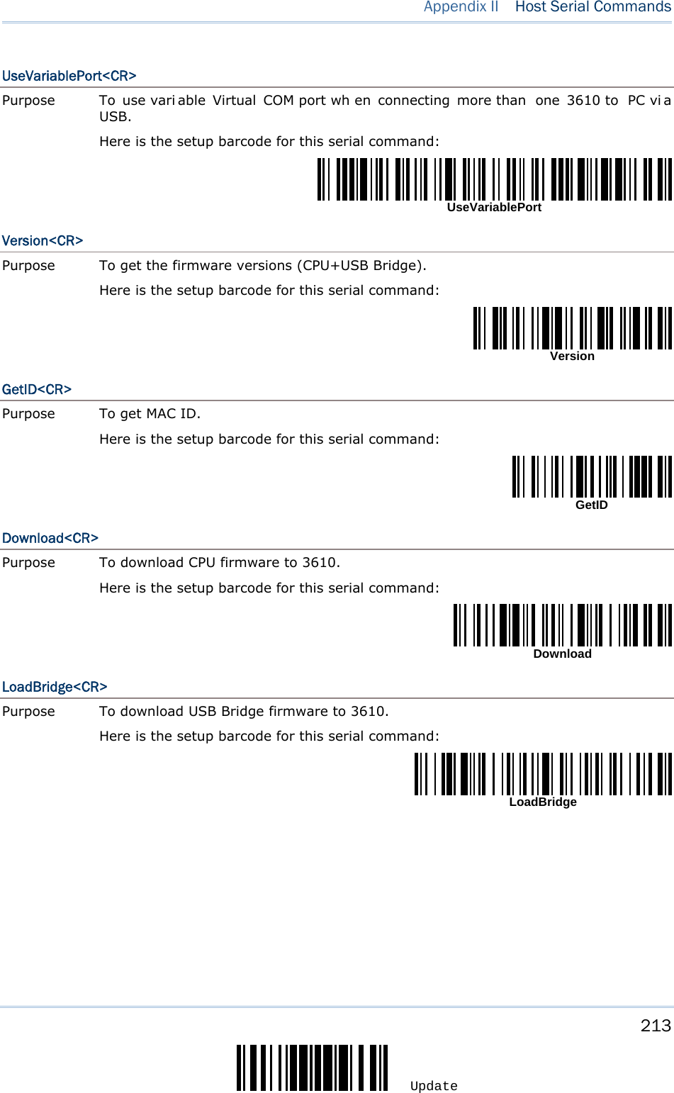
![215 Update F2 SP 0 @ P ` p INS F3 ! 1 A Q a q DLT F4 " 2 B R b r Home F5 # 3 C S c s End F6 $ 4 D T d t Up F7 % 5 E U e u Down F8 & 6 F V f v Left F9 ' 7 G W g w BS F10 ( 8 H X h x HT F11 ) 9 I Y i y LF F12 * : J Z j z Right ESC + ; K [ k { PgUp Exec , < L \ l | CR CR* - = M ] m } PgDn . > N ^ n ~ F1 / ? O _ o Dly ENTER* Note: (1) ~: Digits of numeric keypad. (2) CR*/Send/ENTER*: ENTER key on the numeric keypad. Appendix III KEYBOARD WEDGE TABLE](https://usermanual.wiki/CipherLab/1663/User-Guide-1860865-Page-226.png)
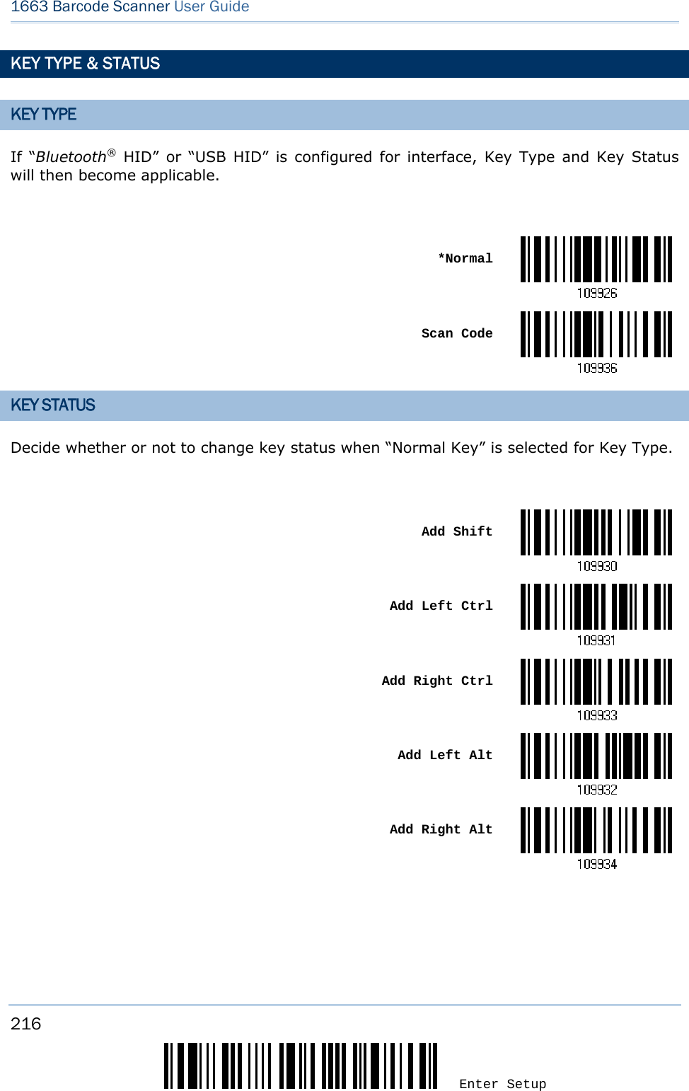

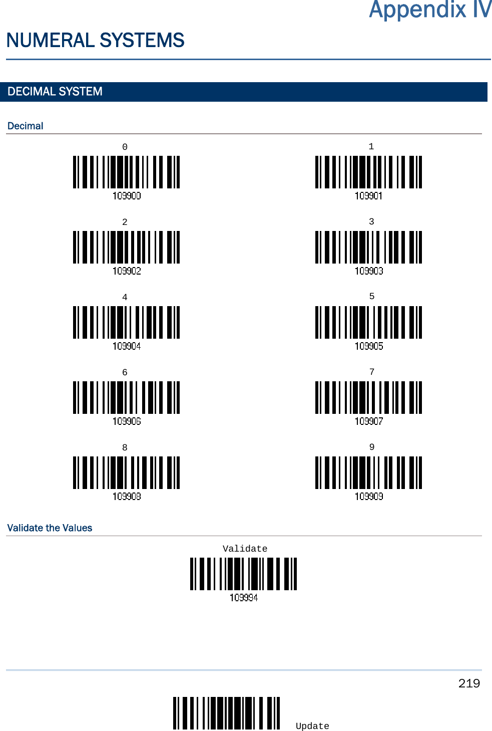
![221 Update Appendix IV Numeral Systems Validate the Values ASCII TABLE 0 DLE SP 0 @ P ` p 1 SOH DC1 ! 1 A Q a q 2 STX DC2 " 2 B R b r 3 ETX DC3 # 3 C S c s 4 EOT DC4 $ 4 D T d t 5 ENQ NAK % 5 E U e u 6 ACK SYN & 6 F V f v 7 BEL ETB ' 7 G W g w 8 BS CAN ( 8 H X h x 9 HT EM ) 9 I Y i y A LF SUB * : J Z j z B VT ESC + ; K [ k { C FF FS , < L \ l | D CR GS - = M ] m } E SO RS . > N ^ n ~ F SI US / ? O _ o DEL Validate](https://usermanual.wiki/CipherLab/1663/User-Guide-1860865-Page-232.png)