CipherLab 1663 Bluetooth Barcode Scanner User Manual 1663 Barcode Scanner
CipherLab Co., Ltd. Bluetooth Barcode Scanner 1663 Barcode Scanner
user manual

1663 Blustooth Barcode Scanner
Setup barcodes included.
Version 1.00

Copyright © 2011~2012 CIPHERLAB CO., LTD.
All rights reserved
The software contains proprietary information of CIPHERLAB CO., LTD.; it is provided
under a l icense agreement conta ining restrictions on use and disclosure and is also
protected by copyright law. Reverse engineering of the software is prohibited.
Due to continued product development this information may change without notice. The
information and intellectual property contained herein is confidential between CIPHERLAB
and the client and remains the exclusive property of CIPHERLAB CO., LTD. If you find
any problems in the documentation, please report them to us in writing. CIP HERLAB
does not warrant that this document is error-free.
No part of t his publication may be reprodu ced, stored in a ret rieval system, or
transmitted in any form or by any mea ns, electronic, mecha nical, photocopying,
recording or otherwise without the prior written permission of CIPHERLAB CO., LTD.
For product consultancy and technical support, please contac t your local sales
representative. Also, you may visit our web site for more information.
The CipherLab logo is a registered trademark of CIPHERLAB CO., LTD.
All brand, product and service, and trademark names are the property of their reg istered
owners.
The editorial use of these names is for ide ntification as wel l as t o the benefit of the
owners, with no intention of infringement.
CIPHERLAB CO., LTD.
Website: http://www.cipherlab.com

FOR USA
This equipment has been tested and found to comply with the limits for a Class B digital
device, pursuant to Part 15 of the FCC Rul es. These l imits are d esigned to provide
reasonable protection against harmful interference in a residen tial installation. This
equipment generates uses and can radiate radio frequency en ergy and, if not installed
and used in accordance with the instructions, may cause h armful interference to radio
communications. However, there is n o guarantee that interference will not occur in a
particular installation. If th is equipment does cau se harmful interference to radio or
television reception, which can be determined by turning the equipment off and on, the
user is encouraged to try to correct the in terference by one or more of the following
measures:
Reorient or relocate the receiving antenna.
Increase the separation between the equipment and receiver.
Connect the equipment into an o utlet on a circuit different from t hat to which the
receiver is connected.
Consult the dealer or an experienced radio/TV technician for help.
This device complies with Part 15 of the FCC Rules. Operation is subject to the following
two conditions: (1) This device may not cause harmful interference, and (2) this device
must accept any interference received, including interference that may cause undesired
operation.
FOR CANADA
This digital apparatus does not exceed the Class B limits for radio noise emission s from
digital apparatus as set out in the interference-causing equipment standard entitled
"Digital Apparatus," ICES-003 of In dustry Canada. This device complies w ith Part 15 of
the FCC Rules. Operation is subject to the following two conditions: (1) This device may
not cause harmful interference, and (2) this device must accept any interference received,
including interference that may cause undesired operation.
Cet appareil n umerique respecte les l imites de bru its radioelectriques applicables au x
appareils numeriques de Classe B prescrites dans la norme su r le mat erial brouilleur:
"Appareils Numeriques," NMB-003 edictee par l'Industrie.
IMPORTANT NOTICES

FOR HAND-HELD PRODUCT WITH RF FUNCTIONS
The 1663 unit (FCC ID: Q3N-1663) complies with FCC radiation exposure limits set forth
for uncontrolled environment and meets the FCC radio frequency (RF) Exposure
Guidelines in Supplement C to OET65. The unit has very low level of RF energy that it is
deemed to comply without testing of specific absorption ratio (SAR).
The 3610 unit (FCC ID: Q3N-3610) complies with FCC radiation exposure limits set forth
for an uncontrolled environment. This equipment should be installed and operated w ith
minimum distance 20 cm between the radiator & bod y. It on ly operated in hand-hel d
used. If only transfer data to the host cordless, please keep the minimum distance 20 cm
between machine & body.
SAFETY PRECAUTIONS
RISK OF EXPLOSION IF BATTERY IS REPLACED BY AN INCORRECT TYPE.
DISPOSE OF USED BATTERIES ACCORDING TO THE INSTRUCTIONS.
The use of an y batteries or ch arging devices, which are not originally sold or
manufactured by CipherLab, will void your warranty and may cause damage to
human body or the product itself.
DO NOT disassemble, incinerate or short circuit the battery.
DO NOT expose the scanner or the battery to any flammable sources.
For green-environment issue, it's important that batteries should be recy cled in a
proper way.
Under no circumstances, internal components are self-serviceable.
CARE & MAINTENANCE
Use a clean cloth to wipe dust off the scanning window and the body of the sca nner
as well as the charging device. DO NOT use/mix any bleach or cleaner.
If you want to put away the scanner for a period of time, download the collected data
to a host computer when in the memory mode, and then take out the battery. Store
the scanner and battery separately.
When the scanner resumes its work, make su re the battery is fully charged before
use.
If you shall find the scanner malfunctioning, write down the specific scenario and
consult your local sales representative.

Version Date Notes
1.00 Nov. 27, 2012 Initial release
RELEASE NOTES

CONTENTS
IMPORTANT NOTICES ...................................................................................................................... - 3 -
For USA .......................................................................................................................................... - 3 -
For Canada .................................................................................................................................... - 3 -
For Hand-held Product with RF Functions ................................................................................... - 4 -
Safety Precautions ........................................................................................................................ - 4 -
Care & Maintenance ..................................................................................................................... - 4 -
RELEASE NOTES .............................................................................................................................. - 5 -
INTRODUCTION.................................................................................................................................... 1
Get Familiarized with 1663 and 3610 ............................................................................................ 2
Install the Battery into 1663 ....................................................................................................... 2
Charge the Battery ....................................................................................................................... 3
Charge the Battery via Charger ................................................................................................... 4
Use 3610...................................................................................................................................... 5
Inside the Package............................................................................................................................ 6
Product Highlights ............................................................................................................................. 6
Symbologies Supported .................................................................................................................... 7
QUICK START ....................................................................................................................................... 9
Enter Configuration Mode...............................................................................................................11
Exit Configuration Mode..................................................................................................................11
Default Settings...............................................................................................................................12
Save User Settings as Defaults.................................................................................................12
Restore User Defaults................................................................................................................12
Restore System Defaults ........................................................................................................... 12
Read a Setup Barcode....................................................................................................................13
Configure Parameters................................................................................................................13
List the Current Settings............................................................................................................17
Create One-Scan Setup Barcodes..................................................................................................19
UNDERSTANDING THE BARCODE SCANNER .................................................................................... 21
1.1 Battery .......................................................................................................................................21
1.1.1 Power Level ......................................................................................................................22
1.1.2 How to Operate the Scanner ...........................................................................................22
1.1.3 Auto Power Off & Power-Saving....................................................................................... 23
1.2 Memory .....................................................................................................................................26
1.2.1 Transmit Buffer ................................................................................................................26
1.2.2 Memory Mode ..................................................................................................................26
1.2.3 Free Memory ....................................................................................................................28
1.3 LED Indicator ............................................................................................................................29
1.3.1 Good Read LED ................................................................................................................30
1.3.2 Good Read LED Duration.................................................................................................30
1.4 Beeper.......................................................................................................................................31

1663 Barcode Scanner User Guide
1.4.1 Beeper Volume.................................................................................................................32
1.4.2 Good Read Beep ..............................................................................................................33
1.4.3 Low Battery Alarm ............................................................................................................34
1.5 Vibrator......................................................................................................................................34
1.5.1 Good Read Vibrator..........................................................................................................34
1.5.2 Good Read Vibrator Duration ..........................................................................................34
1.6 Send “NR” to Host ....................................................................................................................35
1.7 Scan Modes ..............................................................................................................................36
1.7.1 Continuous Mode.............................................................................................................37
1.7.2 Test Mode.........................................................................................................................37
1.7.3 Laser Mode.......................................................................................................................38
1.7.4 Auto Off Mode...................................................................................................................38
1.7.5 Auto Power Off Mode .......................................................................................................38
1.7.6 Alternate Mode.................................................................................................................39
1.7.7 Aiming Mode..................................................................................................................... 39
1.7.8 Multi-Barcode Mode.........................................................................................................40
1.8 Scanning Timeout.....................................................................................................................41
1.9 Delay between Re-read ............................................................................................................42
1.10 Read Redundancy for All Symblogies ...................................................................................43
1.11 Addon Security for UPC/EAN Barcodes ................................................................................44
1.12 Negative Barcodes .................................................................................................................44
1.13 Effective Decoding Area.........................................................................................................45
1.13.1 Positioning Window........................................................................................................45
1.13.2 Adjusting Window...........................................................................................................46
1.14 Use Direct USB Cable.............................................................................................................47
1.14.1 Direct USB Interface ......................................................................................................47
1.14.2 Disable Direct USB Interface.........................................................................................47
1.15 Pager Beep Duration..............................................................................................................48
1.16 Time Stamp.............................................................................................................................49
1.16.1 DATE AND TIME SETTINGS............................................................................................49
1.16.2 SEPARATOR FOR DATE AND TIME ................................................................................51
1.16.3 DATE FORMAT ................................................................................................................52
1.17 Hardware Reset......................................................................................................................53
1.17.1 Restore System Defaults...............................................................................................53
1.17.2 Reset Connection...........................................................................................................53
SELECTING OUTPUT INTERFACE ....................................................................................................... 55
2.1 Bluetooth® HID..........................................................................................................................56
2.1.1 Activate Bluetooth® HID & Select Keyboard Type..........................................................57
2.1.2 Reset Connection.............................................................................................................58
2.1.3 Keyboard Settings............................................................................................................59
2.1.4 Inter-Character Delay .......................................................................................................64
2.1.5 Inter-Function Delay.........................................................................................................65
2.1.6 HID Character Transmit Mode.........................................................................................66
2.1.7 Special Keyboard Feature ...............................................................................................66
2.1.8 Keypad Support for iPhone/iPad ....................................................................................66
2.1.9 Simple Pairing for iPhone/iPad .......................................................................................67
2.2 Bluetooth® SPP Slave...............................................................................................................68
2.2.1 Activate Bluetooth® SPP Slave Mode .............................................................................68

1663 Barcode Scanner
User Guide
2.2.2 Inter-Function Delay.........................................................................................................68
2.2.3 ACK/NAK Timeout............................................................................................................69
2.3 Bluetooth® SPP Master ............................................................................................................70
2.3.1 Activate Bluetooth® SPP Master Mode...........................................................................70
2.3.2 Inter-Function Delay.........................................................................................................71
2.3.3 ACK/NAK Timeout............................................................................................................72
2.3.4 Switch between Master/Slave Mode..............................................................................72
2.4 USB HID via 3610.....................................................................................................................73
2.4.1 Activate USB HID & Select Keyboard Type .....................................................................74
2.4.2 Keyboard Settings............................................................................................................75
2.4.3 Inter-Character Delay .......................................................................................................81
2.4.4 Inter-Function Delay.........................................................................................................82
2.4.5 HID Character Transmit Mode.........................................................................................82
2.4.6 Special Keyboard Feature ...............................................................................................82
2.5 USB Virtual COM (CDC) via 3610 ............................................................................................83
2.5.1 Activate USB Virtual COM ................................................................................................83
2.5.2 Activate USB Virtual COM_CDC .......................................................................................83
2.5.3 Inter-Function Delay.........................................................................................................83
2.5.4 ACK/NAK Timeout............................................................................................................84
2.6 Direct USB HID.......................................................................................................................... 85
2.6.1 Activate USB HID & Select Keyboard Type .....................................................................86
2.6.2 Keyboard Settings............................................................................................................87
2.6.3 Inter-Character Delay .......................................................................................................93
2.6.4 Inter-Function Delay.........................................................................................................94
2.6.5 HID Character Transmit Mode.........................................................................................94
2.6.6 Special Keyboard Feature ...............................................................................................94
2.7 Direct USB Virtual COM ............................................................................................................95
2.7.1 Activate USB Virtual COM ................................................................................................95
2.7.2 Activate USB Virtual COM_CDC .......................................................................................95
2.7.3 Inter-Function Delay.........................................................................................................95
2.7.4 ACK/NAK Timeout............................................................................................................96
SET UP A WPAN CONNECTION ..........................................................................................................97
3.1 Connecting via 3610 ................................................................................................................98
3.1.1 Connect to 3610 .............................................................................................................. 98
3.1.2 Change Interface..............................................................................................................99
3.2 Connecting via Bluetooth® Dongle ........................................................................................100
3.2.1 Change Interface............................................................................................................100
3.2.2 Configure Related Settings............................................................................................101
3.2.3 Connect to Dongle..........................................................................................................104
CHANGE SYMBOLOGY SETTINGS....................................................................................................111
4.1 Codabar...................................................................................................................................112
4.1.1 Security Level .................................................................................................................112
4.1.2 Start/Stop Characters Selection ...................................................................................112
4.1.3 Start/Stop Transmission................................................................................................113
4.1.4 CLSI Conversion .............................................................................................................113
4.2 Code 25 – Industrial 25.........................................................................................................114
4.2.1 Start/Stop Pattern Selection .........................................................................................114
4.2.2 Verify Check Digit ...........................................................................................................115
4.2.3 Transmit Check Digit......................................................................................................115

1663 Barcode Scanner User Guide
4.2.4 Code Length Qualification .............................................................................................116
4.3 Code 25 – Interleaved 25......................................................................................................117
4.3.1 Start/Stop Pattern Selection .........................................................................................117
4.3.2 Verify Check Digit ...........................................................................................................118
4.3.3 Transmit Check Digit......................................................................................................118
4.3.4 Code Length Qualification .............................................................................................119
4.4 Code 25 – Matrix 25 ..............................................................................................................120
4.4.1 Start/Stop Pattern Selection .........................................................................................120
4.4.2 Verify Check Digit ...........................................................................................................121
4.4.3 Transmit Check Digit......................................................................................................121
4.4.4 Code Length Qualification .............................................................................................122
4.5 Code 39...................................................................................................................................123
4.5.1 Start/Stop Transmission................................................................................................123
4.5.2 Verify Check Digit ...........................................................................................................123
4.5.3 Transmit Check Digit......................................................................................................124
4.5.4 Standard/Full ASCII Code 39 ........................................................................................124
4.5.5 Security Level .................................................................................................................124
4.6 Code 93...................................................................................................................................125
4.7 Code 128 ................................................................................................................................125
4.7.1 Security Level .................................................................................................................125
4.8 EAN-8.......................................................................................................................................126
4.8.1 Convert to EAN-13..........................................................................................................127
4.8.2 Transmit Check Digit......................................................................................................127
4.9 EAN-13 ....................................................................................................................................128
4.9.1 ISBN Conversion.............................................................................................................129
4.9.2 ISSN Conversion.............................................................................................................129
4.9.3 Transmit Check Digit......................................................................................................129
4.9.4 Security Level .................................................................................................................130
4.10 GS1-128 (EAN-128) .............................................................................................................131
4.10.1 Code ID Transmission..................................................................................................131
4.10.2 Field Separator (GS Character)...................................................................................131
4.11 ISBT 128 ...............................................................................................................................132
4.12 MSI ........................................................................................................................................133
4.12.1 Verify Check Digit.........................................................................................................133
4.12.2 Transmit Check Digit ...................................................................................................133
4.12.3 Code Length Qualification ...........................................................................................134
4.13 French Pharmacode.............................................................................................................135
4.13.1 Transmit Check Digit ...................................................................................................135
4.14 Italian Pharmacode ..............................................................................................................136
4.14.1 Transmit Check Digit ...................................................................................................136
4.15 Plessey ..................................................................................................................................137
4.15.1 Convert to UK Plessey .................................................................................................137
4.15.2 Transmit Check Digit ...................................................................................................137
4.16 GS1 DataBar (RSS Family) ..................................................................................................138
4.16.1 Code ID Selection ........................................................................................................138
4.16.2 GS1 DataBar Omnidirectional (RSS-14).....................................................................139
4.16.3 GS1 DataBar Expanded (RSS Expanded)...................................................................141
4.16.4 GS1 DataBar Limited (RSS Limited) ...........................................................................142
4.17 Telepen .................................................................................................................................143

1663 Barcode Scanner
User Guide
4.17.1 Telepen Output – Full ASCII/Numeric ........................................................................143
4.18 UPC-A.....................................................................................................................................144
4.18.1 Convert to EAN-13 .......................................................................................................145
4.18.2 System Number Transmission....................................................................................145
4.18.3 Transmit Check Digit ...................................................................................................145
4.19 UPC-E.....................................................................................................................................146
4.19.1 System Number Selection...........................................................................................147
4.19.2 Convert to UPC-A..........................................................................................................147
4.19.3 System Number Transmission....................................................................................148
4.19.4 Transmit Check Digit ...................................................................................................148
DEFINING OUTPUT FORMAT............................................................................................................149
5.1 Letter Case..............................................................................................................................149
5.2 Character Substitution ...........................................................................................................150
5.2.1 Select a Set for Character Substituion .........................................................................151
5.2.2 Symbologies for Character Substitution (All 3 Sets) ....................................................152
5.3 Prefix/Suffix Code...................................................................................................................158
5.4 Code ID....................................................................................................................................159
5.4.1 Select Pre-defined Code ID............................................................................................159
5.4.2 Change Code ID..............................................................................................................161
5.4.3 Clear Code ID Settings...................................................................................................162
5.5 Length Code............................................................................................................................163
5.6 Multi-Barcode Editor...............................................................................................................167
5.6.1 Edit a Concatenation of Barcodes ................................................................................168
5.6.2 Activate the Concatenation of Barcodes ......................................................................169
5.7 Removal of Special Character ...............................................................................................170
APPLYING FORMATS FOR DATA EDITING........................................................................................171
6.1 Activating Editing Formats .....................................................................................................172
6.1.1 Activate Editing Formats................................................................................................172
6.1.2 Exclusive Data Editing....................................................................................................173
6.2 How to Configure Editing Formats.........................................................................................174
6.2.1 Select Format to Configure............................................................................................175
6.2.2 Restore Default Format .................................................................................................176
6.3 Configure Format — Define Data Criteria ..............................................................................177
6.3.1 Applicable Code Type.....................................................................................................177
6.3.2 Data Length ....................................................................................................................184
6.3.3 Matching String & Location ...........................................................................................185
6.4 Configure Format — Define Data Field ..................................................................................186
6.4.1 Start Position ..................................................................................................................186
6.4.2 Field Adjustment ............................................................................................................186
6.4.3 Total Number of Fields...................................................................................................187
6.4.4 Field Settings..................................................................................................................188
6.4.5 Pause Field Setting ........................................................................................................194
6.5 Configure Format — Define Transmission Sequence ...........................................................195
6.6 Programming Examples .........................................................................................................197
6.6.1 Example I ........................................................................................................................197
6.6.2 Example II .......................................................................................................................198

1663 Barcode Scanner User Guide
SPECIFICATIONS ..............................................................................................................................199
FIRMWARE UPGRADE......................................................................................................................201
How to Upgrade Firmware ............................................................................................................201
Using 3610...............................................................................................................................201
Use Direct USB Virtual COM ....................................................................................................203
Use Bluetooth® Dongle ............................................................................................................204
How to Upgrade 3610 Firmware ..................................................................................................206
Upgrade 3610 CPU Firmware .................................................................................................206
Upgrade 3610 USB Bridge Firmware......................................................................................207
HOST SERIAL COMMANDS ..............................................................................................................209
Serial Commands..........................................................................................................................209
Example ....................................................................................................................................210
3610 Setup Barcodes & Serial Commands ................................................................................211
3610 Serial Command Table ..................................................................................................212
Example ....................................................................................................................................214
KEYBOARD WEDGE TABLE ..............................................................................................................215
Key Type & Status .........................................................................................................................216
Key Type....................................................................................................................................216
Key Status ................................................................................................................................216
Example .........................................................................................................................................217
NUMERAL SYSTEMS........................................................................................................................219
Decimal System.............................................................................................................................219
Hexadecimal System.....................................................................................................................220
ASCII Table.....................................................................................................................................221
Entering PIN Code for Authentication ..........................................................................................222
Use Preset PIN..........................................................................................................................222
Disable Authentication or Use Random PIN...........................................................................223

1
Update
CipherLab’s small-form-factor 1600 Series Barcode Scanners are specifica lly designed to
answer the mobile de mands. The palm-sized scanners a re designed to help accelerat e
productivity while lowering the total cost of ownership. Intensive data collection jobs are
made easier with fast, accurate barcode scanning in various working environments,
especially in small businesses. Integrated with short-distance cordless technology, the
small-form-factor scanners are ideal for carr ying in po cket, and thus give workers
tether-free mobility anytime anywhere and g et job done more efficiently. Thi s line of
scanners deliver data over a cordless personal network at a range of up to 10 meters and
a prolonged battery life to keep business running.
Owing to the compact design, extremely low power consumption, and powerful decoding
capability, the 1600 Series Barcode Scanners are the best cho ice for the following
applications –
Receiving in Retail
Product labeling & Tracking
Shelf Product Replenishment
Mobile Point of Sale (POS)
Mobile Inventory Management
Order Picking & Staging
Work-In-Process Tracking
Material Flow Control
Transportation & Distribution
Warehousing
Asset Management
This manual contains information on operating the scanner and using its features. We
recommend you keep one copy of the manual at hand for quick reference or maintenance
purposes. To avoid any improper disposal or oper ation, please read the manual
thoroughly before use.
Thank you for choosing CipherLab products!
INTRODUCTION
2
Enter Setup
1663 Barcode Scanner
User Guide
GET FAMILIARIZED WITH 1663 AND 3610
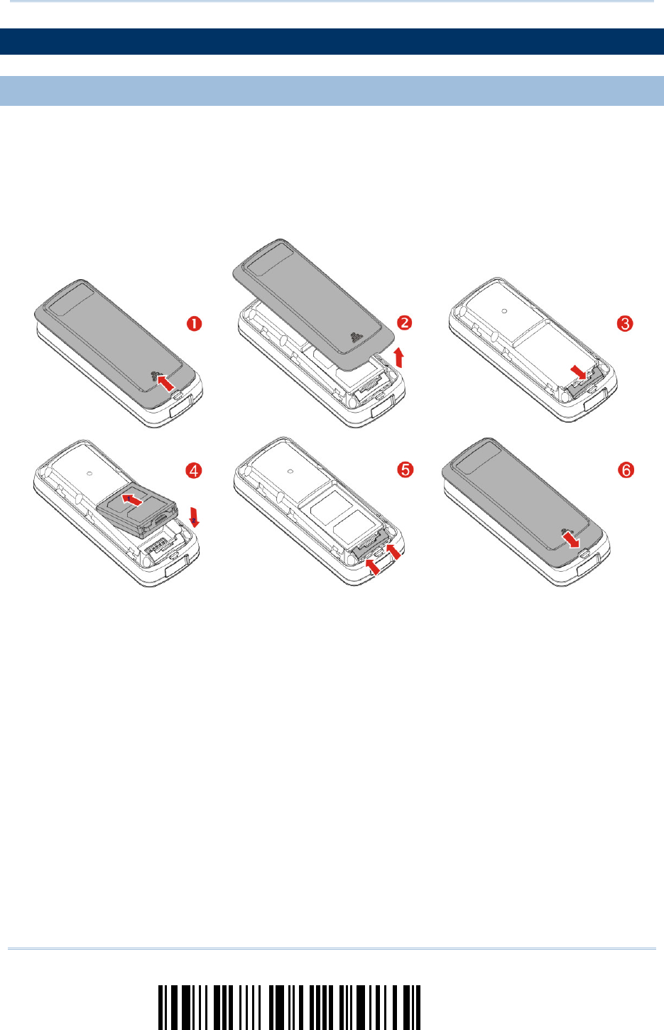
INSTALL THE BATTERY INTO 1663
1) Hold the s canner face down in one hand, press the battery cover, and slide the
battery cover.
2) Remove the battery cover.
3) Push battery lock to unlocked position.
4) Insert the battery into the battery compartment.
Install the supplied 3.7V/850mAh Li-ion battery into the battery compartment.
5) Push battery lock to lock the battery firmly.
6) Replace the battery cover.
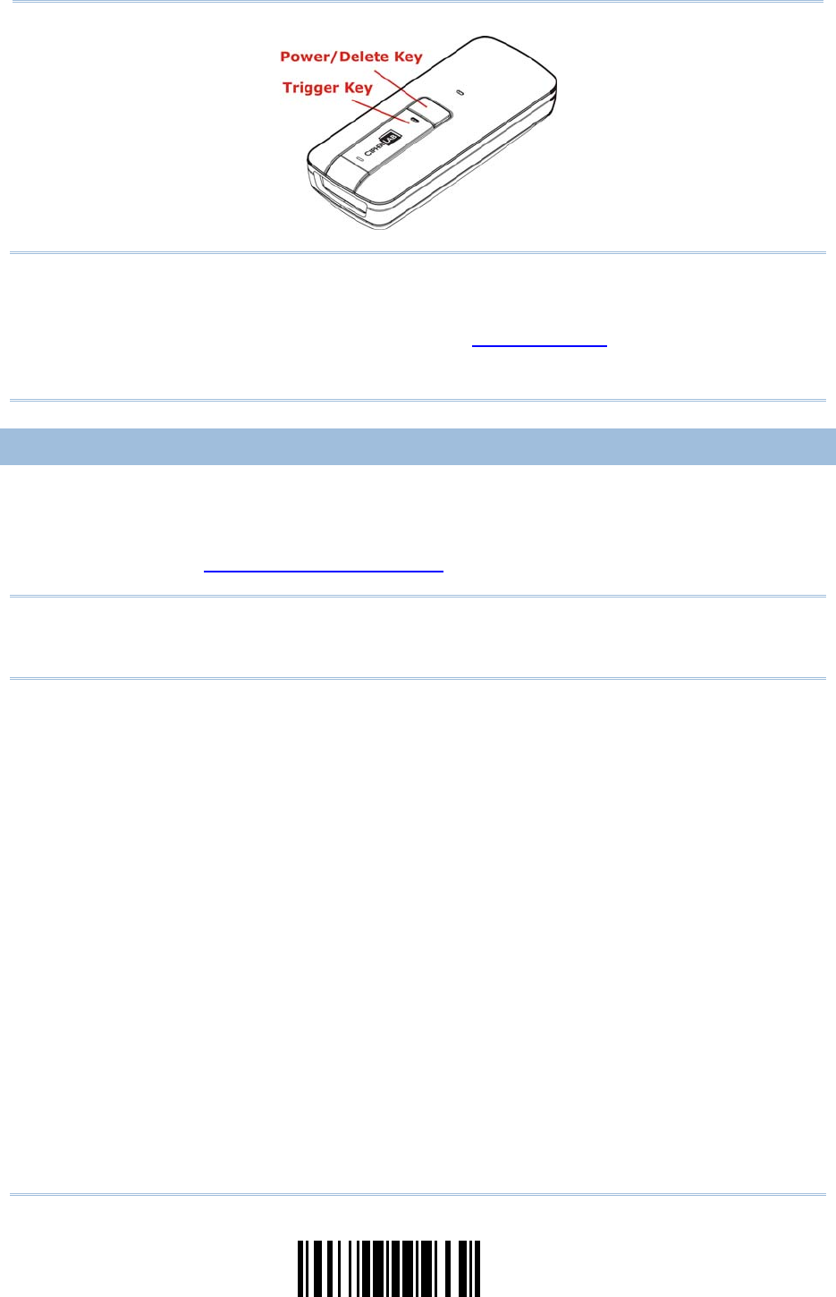
7) Hold down the [Power/Delete] key for about 2 seconds to turn on the scanner.
The scanner will respond with a lon g beep (h igh tone) and its LED indicator will
become solid red and go off.
3
Update
Introduction
Note: (1) To turn off the scanner, press the [Power/Delete] ke y for 2 seconds. The
scanner will respond with two short beeps (h igh tone) and the LED will become
solid red. Release the key. Otherwise, let the scanner t urn off automatically in
specific circumstances. Refer to settings of “Auto Power Off”.
(2) For shipping and storage purposes, remove the battery from the scanner. This
will keep the batteries in good condition for future use.
CHARGE THE BATTERY
The battery may not be fully charged for shipment. For initial use, it is recommended to
fully charge the battery before us ing the scanner. You can use the Direct USB cabl e to
connect the scanner to PC for charging. It takes approximately 4 h ours to fully charge
the battery. Refer to 1.14 Use Direct USB Cable.
Note: Battery charging stops when the temperature drops below 0°C or exceeds 40°C. It
is recommended to c harge the battery at room temperature (18°C to 25°C) for
optimal performance.
1) Install the battery to 1663.
2) Connect 1663 to host computer or notebook via the USB cable.
3) The scanner LED will flash red during charging.
When the charging is complete, the LED will turn off.
When charging errors occur, the LED will turn solid red.
4
Enter Setup
1663 Barcode Scanner
User Guide
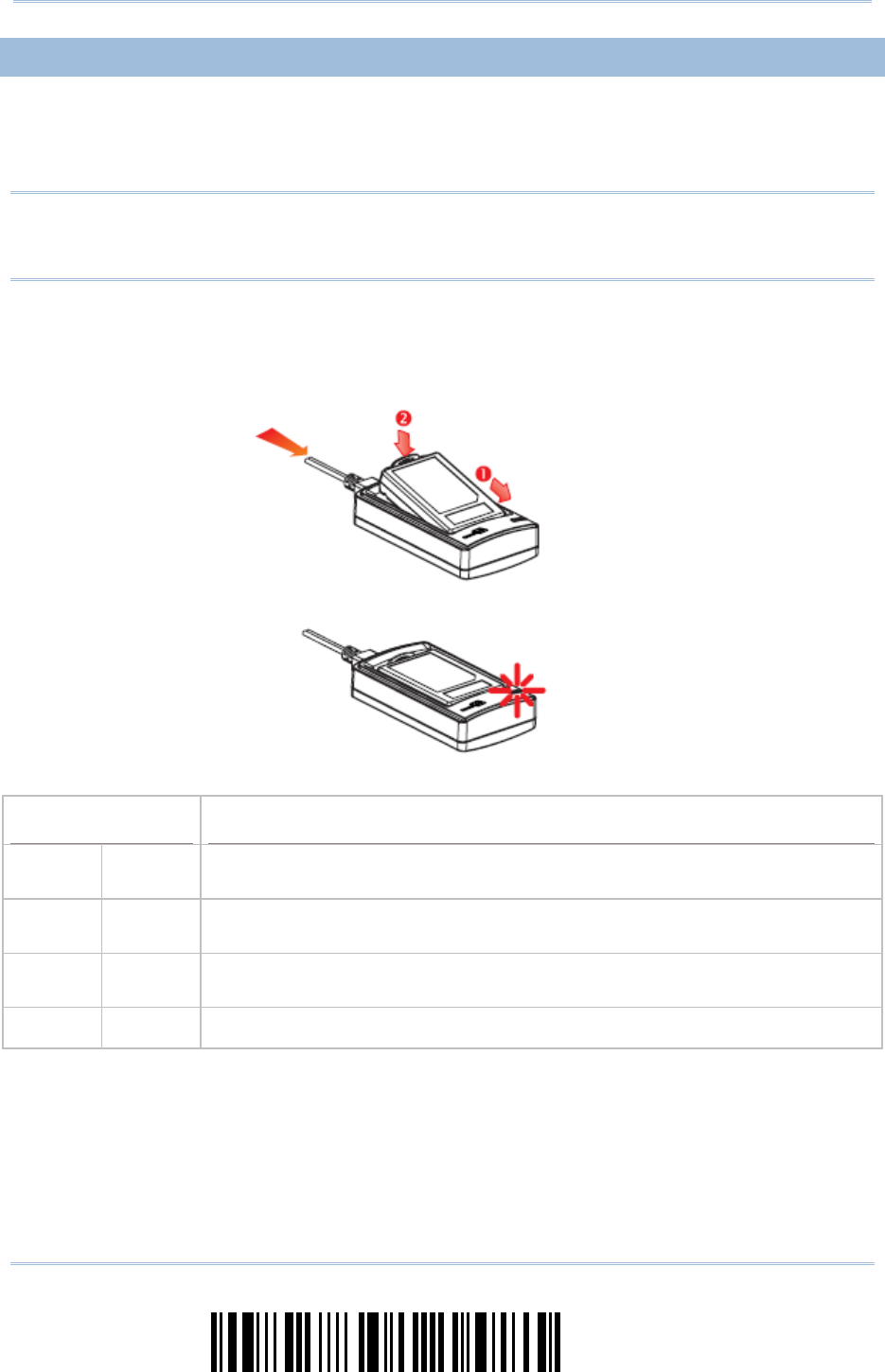
CHARGE THE BATTERY VIA CHARGER
The battery charger is provided for charging the battery outside of the scanner. You may
purchase the charger separately. It takes approximately 3 hours to charge the battery to
full.
Note: Battery charging stops when the temperature drops below 0°C or exceeds 40°C. It
is recommended to c harge the battery at room temperature (18°C to 25°C) for
optimal performance.
1) Insert the battery.
2) Connect the power supply cord to the charger.
3) Connect the other end of the power cord to a suitable power outlet.
Status LED Meaning
Red,
solid
--- Charger power ON (LED on for 0.5 second)
Red,
solid
--- Charging battery
--- Green,
solid
Charging done
--- --- Power or battery not ready
5
Update
Introduction
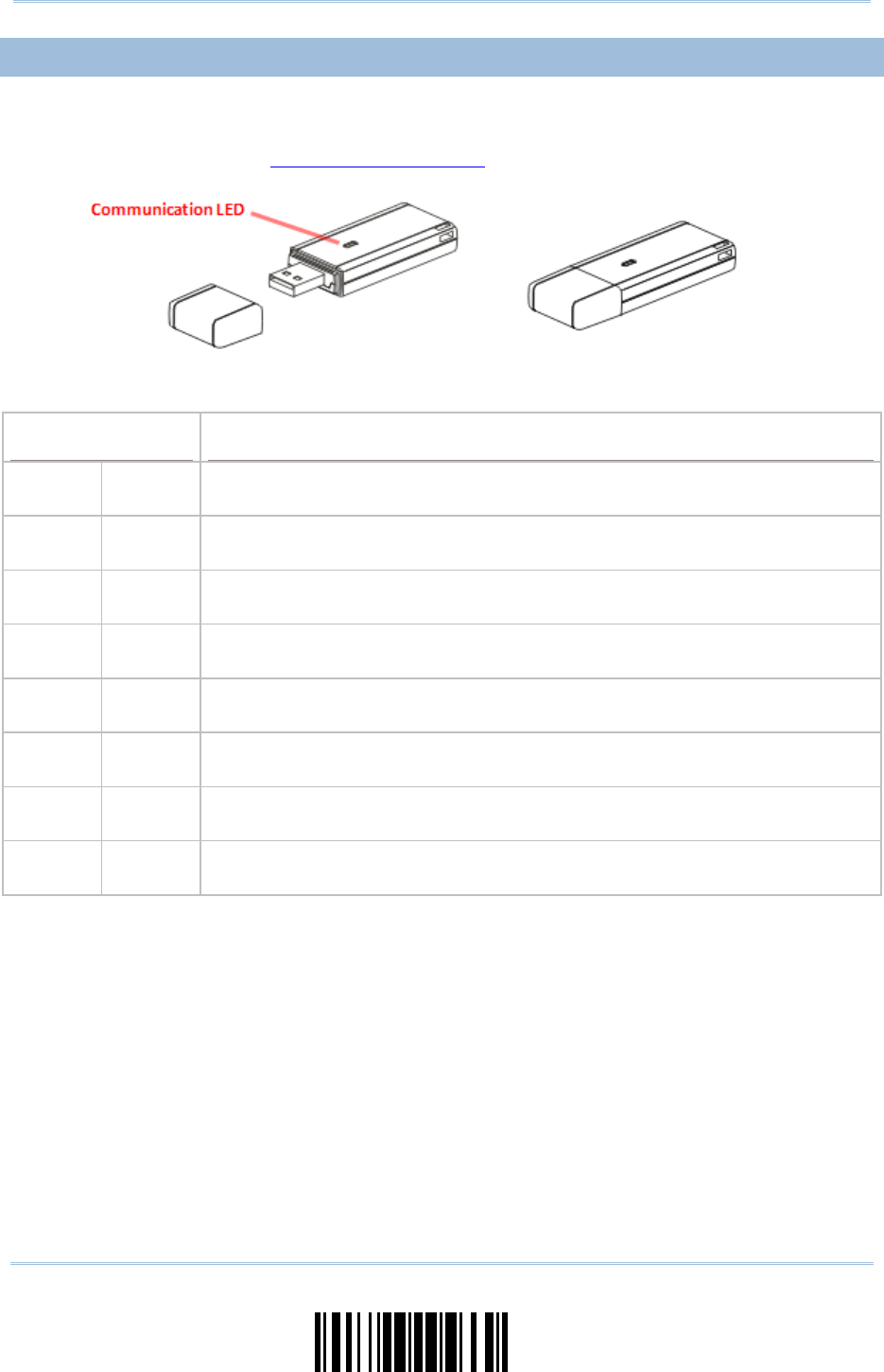
USE 3610
The CipherLab Dongle (3610) is specifically designed fo r the scanner to com municate
with a host computer cordless. The connection between the scanners and 3610 is made
easy and reliable. Refer to 3.1.1 Connect to 3610.
There is one LED indicator provided for communications status.
Communication LED Meaning
--- Blue,
solid
Initialize
Red,
solid
--- Failed to establish a USB connection
Red,
solid
Blue,
flashing
Serial command mode with USB Vi rtual COM: wait 3 seconds for starti ng a
serial command
Red,
flashing
Blue,
flashing
Serial command mode w ith USB HI D: wait 3 seconds for pre ssing [Num
Lock] or [Caps Lock] 5 times via keyboard
--- Blue,
flashing
Wait for connection request from the scanner (Slow flash at 0.5 Hz)
--- Blue,
flashing
Connected with the scanner (Fast flash at 1 Hz)
Red,
solid
Blue,
flashing
Failed to send data to host via USB Virtual COM (Fast flash at 1 Hz)
Red,
flashing
--- Enter Download Mode

6
Enter Setup
1663 Barcode Scanner
User Guide
INSIDE THE PACKAGE
The items included in the package may be di fferent, depending on your order. Save the
box and packaging material for future use in case you need to store or ship the scanner.
1663 Scanner
CipherLab Dongle (3610) Optional
Rechargeable Li-ion Battery Pack
Direct USB Cable
Wristband
Setup Cards
Quick Start Guide
Product CD
Note: The CD-ROM includes this manual and Windows-based ScanMaster software for
configuration, as well as the USB Virtual COM driver.
PRODUCT HIGHLIGHTS
Small-form-factor and built tough to survive drop test.
Extremely low power consumption.
Firmware upgradeable.
Support most popular barcode symbolog ies, including GS1-128 (EAN-128), GS1
DataBar (RSS) etc.
Support Time Stamp and Paging functions.
Support negative barcodes.
Support different scan modes, including Aiming Mode and Multi-Barcode Mode.
LED indicator, beeper and vibrator for status verification or warning.
Beeping tone and duration programmable for Good Read.
4MB flash memory for Memory Mode operation, storing over 240,000 scans based on
EAN-13 barcodes.
Provides up to 10 KB SRAM for reserve buffer while getting out of range over a
wireless personal area network (WPAN), storing up to 640 scans based on EAN-13
barcodes.
Capable of transmitting scanned data, emulating a serial cable (Bluetooth® SPP) or as
keyboard input (Bluetooth® HID), to a notebo ok computer or PDA with Bluetooth®
wireless technology.
Programmable parameters including data output format, editing format, symbologies.
Easy configuration through ScanMaster.
Easy connection through CipherConnect, readily available via online marketplace for
mobile devices running on Android 2.x, BlackBerry 5.x, or Windows Mobile 6.x.

7
Update
Introduction
SYMBOLOGIES SUPPORTED
Most of the popular barcode symbologies ar e supported, as listed below. Each can be
individually enabled or disabled . The scanner will automatically discriminate and
recognize all the symb ologies that are enabled. Refer to Chapter 4 Change Symbology
Settings for details of each symbology.
Symbologies Supported: Enable/Disable Default
Codabar Enabled
Code 93 Enabled
MSI Disabled
Plessey Disabled
Telepen Disabled
Code 128 Enabled
GS1-128 (EAN-128) Disabled
Code 128
ISBT 128 Enabled
Industrial 25 Enabled
Interleaved 25 Enabled
Code 2 of 5
Matrix 25 Disabled
Code 39 Enabled
Italian Pharmacode Disabled
Code 3 of 9
French Pharmacode Disabled
EAN-8 Enabled
EAN-8 Addon 2 Disabled
EAN-8 Addon 5 Disabled
EAN-13 Enabled
EAN-13 & UPC-A Addon 2 Disabled
EAN-13 & UPC-A Addon 5 Disabled
ISBN Disabled
UPC-E0 Enabled
UPC-E1 Disabled
UPC-E Addon 2 Disabled
UPC-E Addon 5 Disabled
EAN/UPC
UPC-A Enabled

8
Enter Setup
1663 Barcode Scanner
User Guide
GS1 DataBar Omnidirectional (RSS-14) Disabled
GS1 DataBar Truncated Disabled
GS1 DataBar Stacked Disabled
GS1 DataBar Stacked Omnidirectional Disabled
GS1 DataBar Limited (RSS Limited) Disabled
GS1 DataBar Expanded (RSS Expanded) Disabled
GS1 DataBar
(RSS)
GS1 DataBar Expanded Stacked Disabled
9
Update
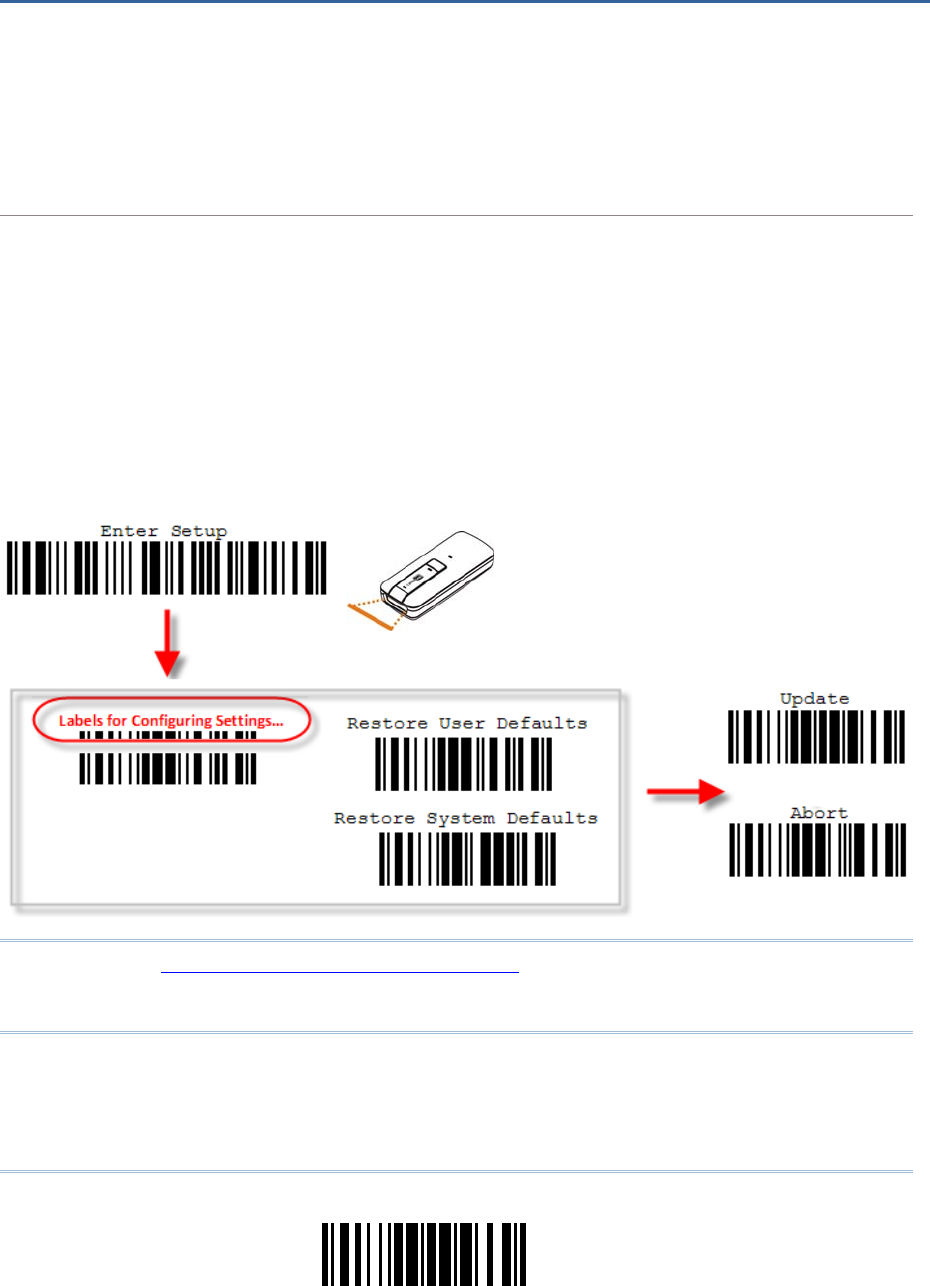
The configuration of the scanner can be done by reading the setup barcodes contained in
this manual or via the ScanMaster software.
This section describes the proce dure of co nfiguring the scanner by reading the setup
barcodes and provides some examples for demonstration.
Configuration Mode
1) Hold down the [Power/Delete] key for 2 seconds to turn on the scanner. It will respond with a
long beep and its LED will come on-off.
2) Read the “Enter Setup” barcode. It will respond with six beeps and i ts LED i ndicator will
become flashing red after reading the barcode.
3) Read more setup barcodes… Most of t he setup barcodes are normal, and the scanner will
respond with two beeps (low-hi gh tone). For special setup barcodes, it requires reading more
than one setup barcode to complete the setting.
4) Read the “Update” or “Abort” barcode. It will respond with six beeps and its LED indicator will
become flashing red after reading the barcode.
5) The scanner will restart automati cally upon reading the “Update ” or “Abort” barcode. It will
respond with a long beep and its LED will come on-off.
Note: Refer to Appendix II Host Serial Commands for how to configure the 3610 dongle
by having the sca nner read 3610-relate d setup barcodes or using ser ial
commands.
QUICK START
10
Enter Setup
1663 Barcode Scanner User Guide
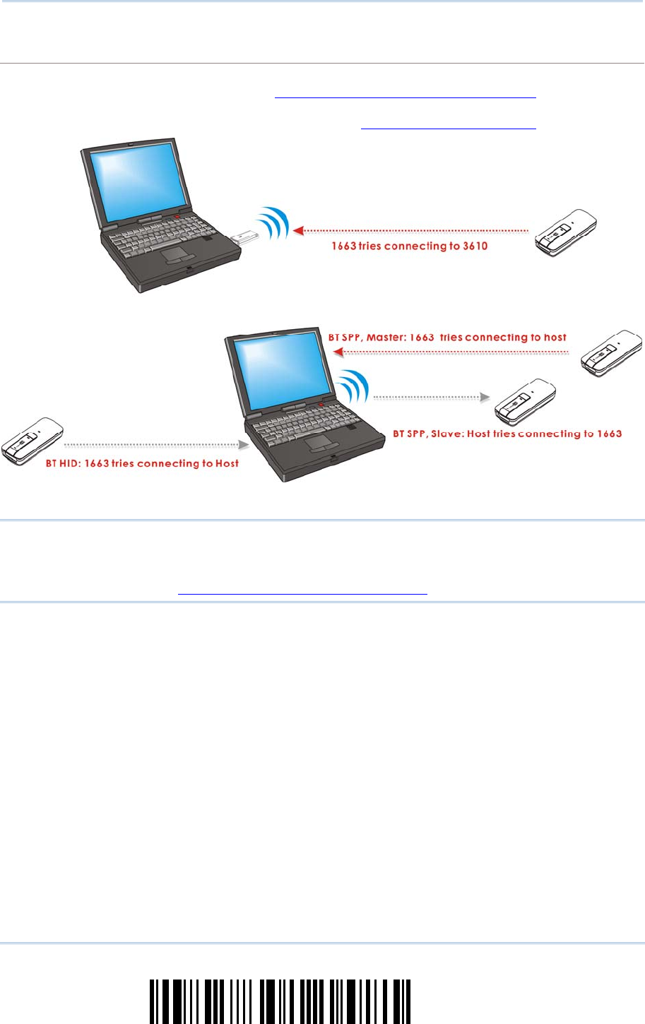
Working Mode
Upon powering up, the scanner will try to esta blish a connecti on with 3610 or a computer wi th
Bluetooth® wireless technology. Refer to Chapter 3 - Set up a WPAN Connection for details. The
connection between the scanners and 3610 is made ea sy and rel iable. Now, it also supports
Bluetooth® SPP Master Mode as an alternative. Refer to 2.3 Bluetooth® SPP Master.
Note: If USB Virtual COM or Bluetooth® SPP is selected for output interface, the host can
directly send serial commands to configure the scanner. For example, run
HyperTerminal.exe and type the 6-digit command located under each setup
barcode. Refer to Appendix II Host Serial Commands.

11
Update
Quick
Start
ENTER CONFIGURATION MODE
For the scanner to ent er the configuration mode, read the "Enter Setup" barco de, which
can be located at the bottom of almost every even page of this manual.
The scanner will respond with six beeps and its LED indicator will become flashing red
after reading the barcode.
Enter Setup
For configuring scanner parameters, see “Read a Setup Barcode” below.
EXIT CONFIGURATION MODE
For the scanner to sa ve settings and exit the configuration mode, read the “Update”
barcode, which can be located at the bottom of almost every odd page of this manual.
Exit the configuration mode without saving any changes; read the “Abort” barcode
instead.
Just like reading the “Enter Setup” barcode, the scanner will respond with six beeps
and its LED indicator will be come flashing red after reading the barcode. Wait for a
few seconds for the scanner to restart itself.
Update
Abort

12
Enter Setup
1663 Barcode Scanner User Guide
DEFAULT SETTINGS
SAVE USER SETTINGS AS DEFAULTS
For the scanner to keep the customized settings as user defaults, you must read the
“Save as User Defaults” barcode. This is a normal setup barcode, and the sca nner will
respond with two beeps (low-high tone).
After reading the “Update” barcode, the current settings will be saved as u ser
defaults.
S
ave as User
Defaults
RESTORE USER DEFAULTS
For the sca nner to restore the user defaults , which you have saved earlier, you m ust
read the “Restore User Defaults” barcode. This is a normal setup barcode, and the
scanner will respond with two beeps (low-high tone).
After reading the “Update” barcode, all t he parameters of the scanner will return to
their customized values.
Restore User
Defaults
RESTORE SYSTEM DEFAULTS
For the sc anner to r estore the factory def aults, read the “Res tore System Defaul ts”
barcode. This is a n ormal setup barcode, and the scanner will respond with two beeps
(low-high tone). After reading the “Update” barcode, all the parameters of the scanner
will return to their default values. The current connection record will be cleared as well.
Refer to 1.17.1 Restore System Defaults for the key combination used to restore defaults
during operation.
For 3610 to restore factory defaults, refer to 3610 Setup Barcodes & Serial Commands.
Restore System
Defaults
Note: The system default value (if there is one) for each setting is indicated by a n
asterisk “*”.
13
Update
Quick
Start
READ A SETUP BARCODE
CONFIGURE PARAMETERS
For most of the scanner parameters, only one read is required to set them to new values.
The scanner will respond with two beeps ( low-high tone) when each parameter is set
successfully. Refer to Create One-Scan Setup Barcodes.
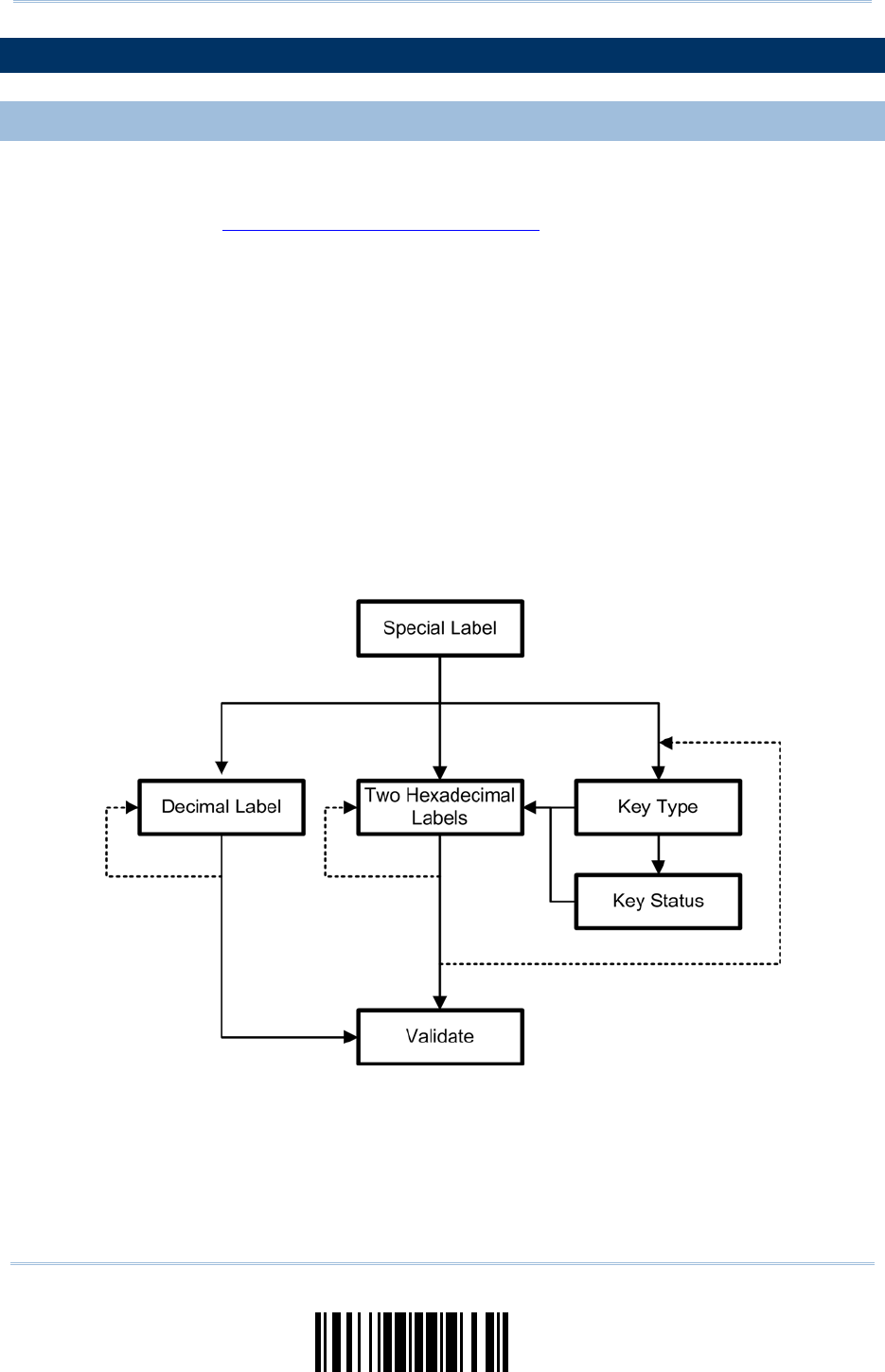
But for a number of special parameters, multiple reads are requ ired to complete the
setting. In this case, the scanner will respond with a short beep t o indicate it needs to
read more setup barcodes. These special pa rameters may require reading one or more
setup barcodes, such as:
Numeric barcodes, say, for keyboard type, inter-character delay, length qualification
Hexadecimal barcodes, say, for character strings as prefix, suffix, etc.
When “Bluetooth® HID” or “USB HID” is configured for interface, Key Type and Key
Status will then become applica ble. Decide whether to ch ange key status when
“Normal Key” is selected for Key Type.
To complete the configuration of t hese special parameters, it requires reading the
“Validate” barcode, and the scanner will respond with two beeps ( low-high tone) to
indicate the input values are validated.
14
Enter Setup
1663 Barcode Scanner User Guide
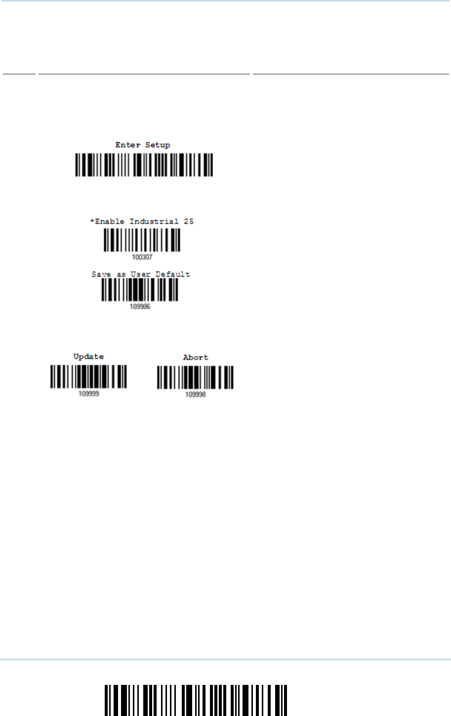
The example below shows ho w to save your se ttings as “User Default” so that you may
restore user defaults at a later time:
Steps Action LED/Beeper Response when Successful
1) Power on the scanner…
T
he scanner will respond with a long beep
(high tone)
and its LED indicator will
become solid red and go off.
2) Enter the Configuration Mode…
T
he scanner will respond with six beeps
(high-low tone repeats three ti mes), and
its LED indicator will be flashing red.
3) Read a Setup barcode…
For example,
The scanner will respond wi th two beeps
(low-high tone) if reading a normal setup
barcode.
4) Exit the Configuration Mode…
OR
Same as for Enter the Configuration Mode.
5) The scanner will automatically restart itself… Same as for Power on the scanner.
* When any configuration error occurs...
T
he scanner will respond wi th one long
beep (low tone).
15
Update
Quick
Start
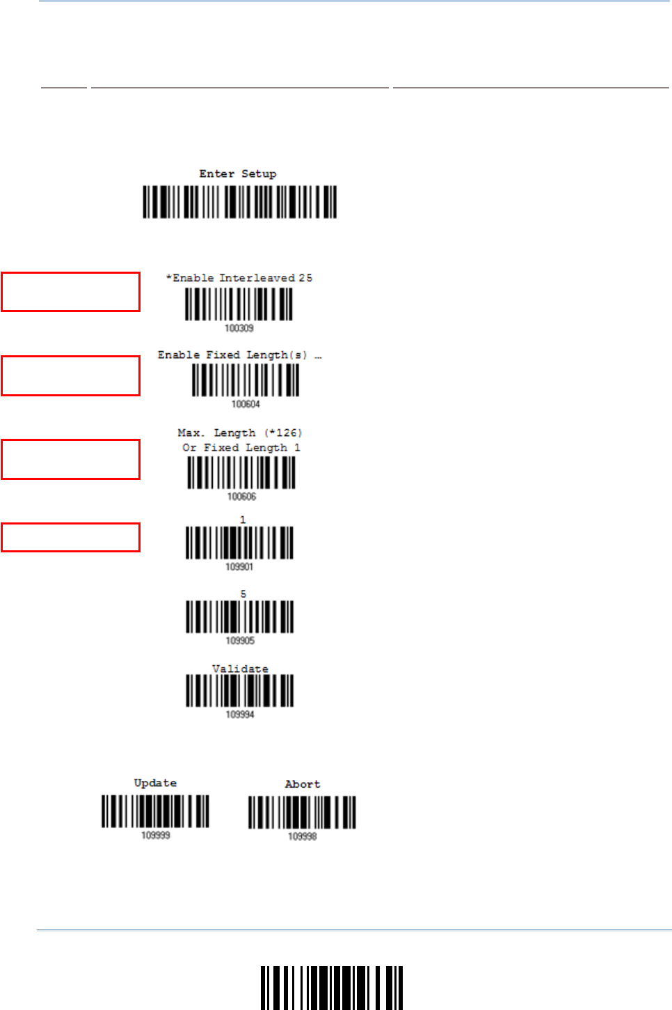
The example below shows how to set numeric parameters:
Steps Action LED/Beeper Response when Successful
1) Power on the scanner...
T
he scanner will respond with a long beep
(high tone)
and its LED indicator will
become solid red and go off.
2) Enter the Configuration Mode…
T
he scanner will respond with six beeps
(high-low tone repeats three ti mes), and
its LED indicator will become flashing red.
Read a Setup barcode...
For example,
T
he scanner will respond w ith two beeps
(low-high tone) if reading a normal setup
barcode.
3)
T
he scanner will respond wi th one short
beep if r eading a special setup barcode
such as “Max. Length”, i ndicating the
setup requires reading more barcodes.
Read the “Decimal Value” barcode(s).
Refer to Appendix IV “Decimal
System”
T
he scanner will respond w ith two beeps
(low-high tone) when th e input values are
validated.
4) Exit the Configuration Mode…
OR
Same as for Enter the Configuration Mode.
5) The scanner will automatically restart itself… Same as for Power on the scanner.
N
ormal setup
barcode
N
ormal setup
barcode
Special setup
barcode
Decimal barcodes
16
Enter Setup
1663 Barcode Scanner User Guide
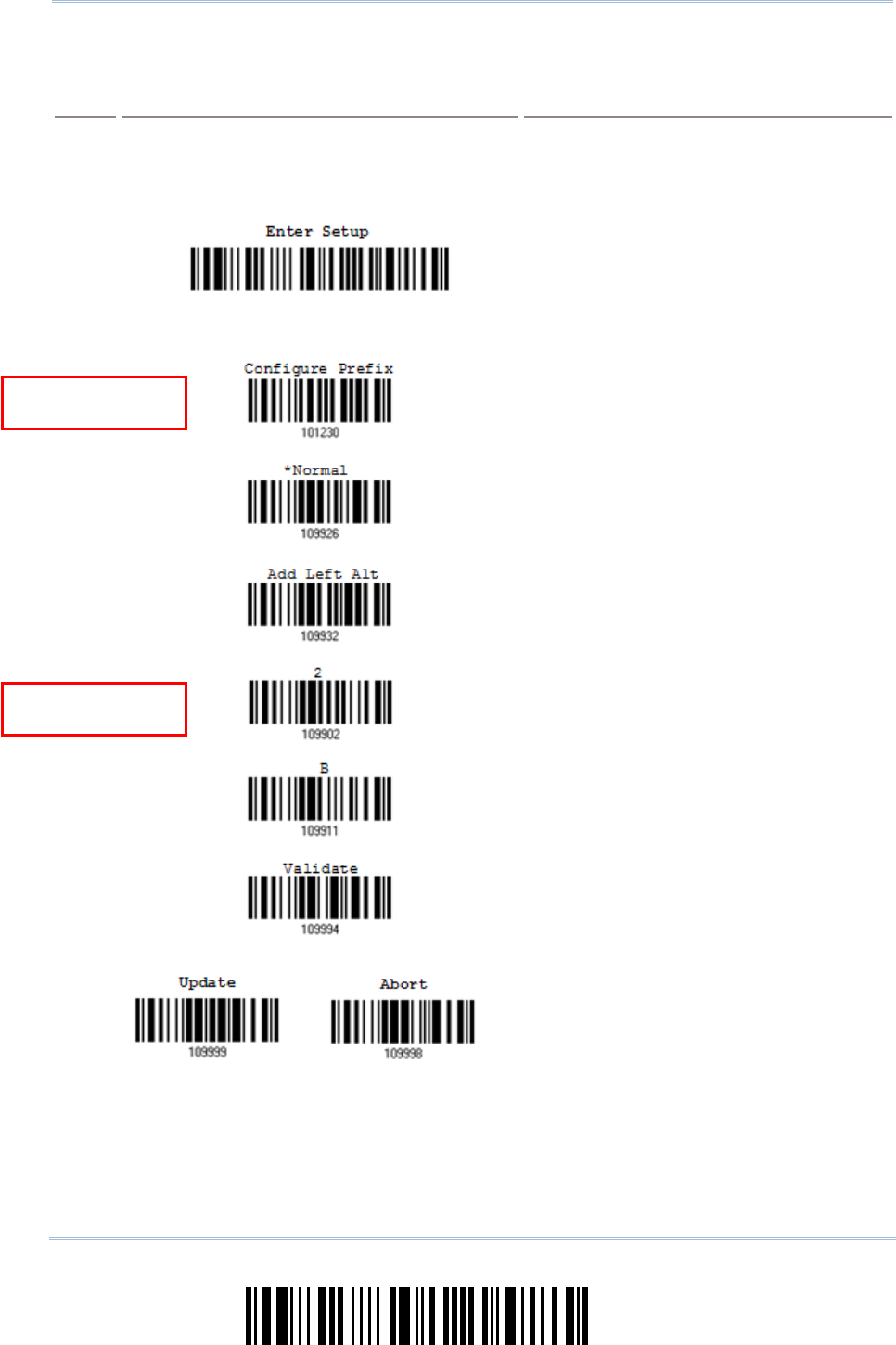
The example below shows how to set string parameters:
Steps Action LED/Beeper Response when Successful
1) Power on the scanner... The scanner will respond with a long beep
(high tone)
and its LED indicator will
become solid red and go off.
2) Enter the Configuration Mode…
T
he scanner will respond with six beeps
(high-low tone repeats three ti mes), and
its LED indicator will become flashing red.
Read a Setup barcode...
For example,
T
he scanner will respond wi th one short
beep if r eading a special setup barcode
such as “Prefix Code”, indicating the setup
requires reading more barcodes.
When “Bluetooth® HID” or “USB HID” is
configured for interface, Key Type and Key
Status will then become appl icable. You
may decide whether or not to change key
status
when “Normal Key” is selected for
Key Type.
Refer to Appendix III
3)
Read the “Hexadecimal Value” barcodes
for the desi red character stri ng. For
example, read “2” and “B” for the sca nner
to prefix the character “+”.
Refer to A ppendix IV “Hexadecimal
System”
The scanner will respond wi th two beeps
(low-high tone) when th e input values are
validated.
4) Exit the Configuration Mode…
OR
Same as for Enter the Configuration Mode.
5) The scanner will automatically restart itself… Same as for Power on the scanner.
Special setup
barcodes
Hexadecimal
barcodes

17
Update
Quick
Start
LIST THE CURRENT SETTINGS
The current settings of all scanner parameters can be sent to the host computer for user
inspection. The listing includes pages as shown below. You can select the page of interest
by having the scanner read the “List Page x” barcode. The scanner will respond with two
beeps (low-high tone) and send the selected page to the host immediately.
List settings regarding Firmware Version, Serial
Number, Interface, Buzzer, Simple Pairing
Status and Other Scanner Parameters
List Page 1
List settings regarding Prefix, Suffix, Code Type
and Length Code Setting List Page 2
List settings regarding Code ID
List Page 3
List settings regarding Readable Symbologies
List Page 4
List settings regarding Symbology Parameters
(1/3) List Page 5
List settings regarding Symbology Parameters
(2/3) List Page 6
List settings regarding Symbology Parameters
(3/3) List Page 7
List settings regarding Editing Format 1
List Page 8
List settings regarding Editing Format 2
List Page 9
List settings regarding Editing Format 3
List Page 10

18
Enter Setup
1663 Barcode Scanner User Guide
List settings regarding Editing Format 4
List Page 11
List settings regarding Editing Format 5
List Page 12
List settings regarding Power and Time
List Page 13
19
Update
Quick
Start
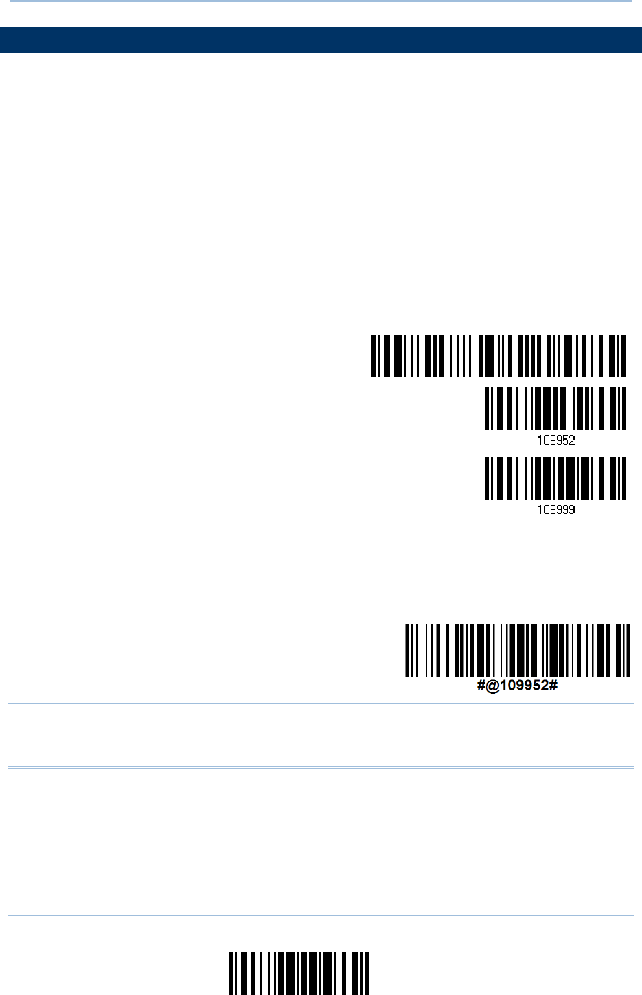
CREATE ONE-SCAN SETUP BARCODES
The fact is most of the scanner pa rameters require only one read for setting new values.
To facilitate configuring the scanner, you may create One-Scan setup barcodes for use.
The requirements of a One-Scan setup barcode are:
a prefix of the “#@” characters
the six digits of command parameters
a suffix of the “#”character
For example, the scanner need s the reading of three setu p barcodes for the command
parameter “109952” to take effect:
Enter Setup
List Page 3
Update
Now, it requires only one read:
One-Scan Setup Barcode for
109952
Note: The scanner will restart automatically upon reading the One-Scan setup barcode
for (1) changing the interface or (2) setting memory mode, enable or disable. It
will respond with a long beep and its LED will come on-off.

20
Enter Setup
1663 Barcode Scanner User Guide

21
Update
This chapter explains the features and usage of the barcode scanner.
IN THIS CHAPTER
1.1 Battery..................................................................... 21
1.2 Memory.................................................................... 26
1.3 LED Indicator ............................................................ 29
1.4 Beeper ..................................................................... 31
1.5 Vibrator.................................................................... 34
1.6 Send “NR” to Host ..................................................... 35
1.7 Scan Modes .............................................................. 36
1.8 Scanning Timeout ...................................................... 41
1.9 Delay between Re-read............................................... 42
1.10 Read Redundancy for All Symblogies........................... 43
1.11 Addon Security for UPC/EAN Barcodes ........................ 44
1.12 Negative Barcodes ................................................... 44
1.13 Effective Decoding Area ............................................ 45
1.14 Use Direct USB Cable................................................ 47
1.15 Pager Beep Duration................................................. 48
1.16 Time Stamp ............................................................ 49
1.17 Hardware Reset ....................................................... 53
1.1 BATTERY
The scanner is battery-powered: Use a rechargeable 3.7 V/850 mAh Li-ion battery. For
intensive data collect ion, please prepare spare battery or batteries for non-stop
operation.
Note: (1) The rechargeable battery for 1663 may not be fully charged when shipped. We
suggest charging it to full before use.
(2) The scanner can be configured to save battery power. Refer to settings of
“Auto Power Off & Power-Saving”, “Sniff Mode”, as well as “Low Battery Alarm”.
Chapter 1
UNDERSTANDING THE BARCODE SCANNER
22
Enter Setup
1663 Barcode Scanner User Guide
1.1.1 POWER LEVEL
Scan the barcode below to get the battery voltage with an interval of 20%.
Spare Power Level
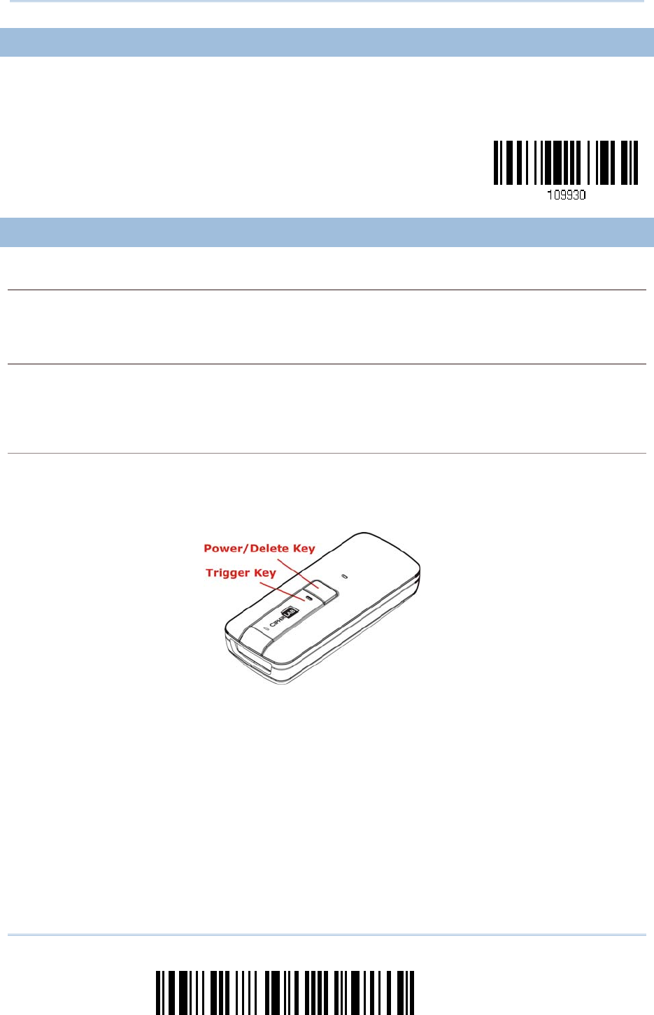
1.1.2 HOW TO OPERATE THE SCANNER
Turn on the scanner…
Press the [Power/Delete] key for 2 seconds. The scanner will respond with a long beep (high tone),
and its LED indicator will become solid red and go off.
Turn off the scanner…
Press the [Power/Delete] key for 2 seconds. The scanner will r espond with two short beeps (hi gh
tone) and the LED will become solid red. Release the key then. Otherwise, let the scanner turn off
automatically in specific circumstances.
Delete the last collected data when in memory mode …
Press the [Power/Delete] key. The scanner will respond with two short be eps (high tone) and the
LED will become solid red. Before the LED goes off (within 1 second), press the [Power/Delete] key
again to confirm the deletion.

23
Update
Chapter 1
Understandin
g
t
he Barcode Scanner
1.1.3 AUTO POWER OFF & POWER-SAVING
The scanner will stay active at power-on, which may be followed by a transition from full
CPU speed to low CPU speed (Power-Saving) to auto shutdown (Auto Power Off).
Power-Saving (1~254 min.; 0= Disable): By default, it is set to stand by at full-speed
for 2 minutes before it enters low-speed mode. If this feature is not desired, set it to
0.
Auto Power Off (1~254 min.; 0= Disable): By default, it is set to automatically shut
down after 10 minutes. If this feature is not desired, set it to 0.
Note: 1. The Power-Saving setting will still take effect once a con nection has been
established successfully, via Bluetooth® HID or SPP.
Before establishing a WPAN connection successfully…
1) The scanner will stay active for a specified period of time (2 minutes by default) for the
following scenarios. Its CPU is running at full speed, and the LED is flashing blue (On/Off ratio
0.5 s: 0.5 s).
(a) waiting for a connection request from the host (Bluetooth® SPP Slave Mode)
(b) trying to connect to the host (Bluetooth® HID or Bluetooth® SPP Master Mode)
(c) trying to connect to 3610
2) If it fails to connect within 2 minutes, the scanner will become inactive to save power for the
remaining period of ti me (the specified value minus 2 mi nutes). Its CPU i s running at l ow
speed, and the LED is flashing red (On/Off ratio 0.3 s: 2.5 s).
Press the [Trigger] key to wake up the scanner when it becomes inactive, and the scanner will
stay active again.
3) If it fails to connect again and again, and finally stays inactive until the specified time interval
for Auto Power Off has e lapsed, the scanner will automatically turn off in order to conserve
battery power.
Hold down the [Power/Delete] key for 2 seconds to turn it on.
Note: For scenarios (a) and (b) in step 1, on your computer you may need to search for
the scanner again.

24
Enter Setup
1663 Barcode Scanner User Guide
After establishing a WPAN connection successfully…
1) Once a WPAN connection is established successfully, the scanner will stay active for a specified
period of time (2 minutes by default) for data transmission. Its CPU i s running at full speed,
and the LED is flashing blue (On/Off ratio 0.02 s: 3 s).
2) If it is idle within 2 minutes, the scanner will become i nactive to save power for the remaini ng
period of time (the specified value minus 2 minutes). Its CPU is running at low speed, and the
LED is flashing red (On/Off ratio 0.3 s: 2.5 s).
Press the [Trigger] key to wake up the scanner when it becomes inactive, and the scanner will
stay active again.
3) If it is idle and finally stays inactive until the specified time interval for Auto Power Off has
elapsed, the scanner will automatically turn off i n order to conserve battery power. The th ree
short beeps will ring out, tone descending from high to low.
Hold down the [Power/Delete] key for 2 seconds to turn it on.
For Bluetooth® HID, the scanner will resume connection with the host upon powering on
again, as long as the host application is running. The three short beeps will ring out, tone
ascending from low to high. If the sc anner fails to resume connecti on, it will try every 5
seconds to re-connect to the host unl ess the “Reset Connecti on” barcode has been
scanned.
For Bluetooth® SPP Slave Mode, the scanner must wait for the host to re-connect.
For Bluetooth® SPP Master Mode, the scanner will resume connection with the host upo n
powering on again, as long as the host app lication is running. The three sho rt beeps will
ring out, tone ascending from low to high. If the scanner fails to resume connection, it will
try every 5 s econds to re-connect to the host unl ess the “Reset Connection” or “Restore
System Defaults” barcode has been scanned.
With the use of 361 0, the scanner wi ll try re-connecti ng to 3 610 whilst the scanner i s
active.

25
Update
Chapter 1
Understandin
g
t
he Barcode Scanner
Auto Off after
0~254 min. (*10)
1) Read the barcode above to sp ecify the time interval in minutes before the sca nner
automatically turns off.
2) Read the “Decimal Value” barcode on page 219. For example, read “1” and “5” for the
scanner to automatically turn off after being idle for 15 minutes.
3) Read the “Validate” barcode on the same page to complete this setting.
Note: Auto Power Off will not take effect when the scanner is in the configuration mode.
Power-
S
aving after
0~254 min. (*2)
1) Read the barcode above to sp ecify the time interval in minutes before the sca nner
enters low-speed mode.
2) Read the “ Decimal Value” barcode on page 219. For example, read “5” for the
scanner to enter low-speed mode after being idle for 5 minutes.
3) Read the “Validate” barcode on the same page to complete this setting.
Note: Power-Saving will not take effect when one of the following conditions is met:
(1) The scanner has already established a BT HID/SPP connection.
(2) The scanner is in the configuration mode.
(3) The scan mode is set to Test, Continuous or Alternate Mode.
(4) The setting value of Power-Saving is greater than that of Auto Power Off.

26
Enter Setup
1663 Barcode Scanner User Guide
1.2 MEMORY
The scanned data can be sent to a host computer immediately via the WPAN connection
or stored in flash memory when the scanner is set to Memory mode.
1.2.1 TRANSMIT BUFFER
By default, the transmit buffer is enabled and ready for use when the scanner is out of
range. Upon reading a barcode successfully within range, the scanner responds with one
short beep (high tone) and its LED indicator becomes solid green and goes off. However,
the host computer may not receive the data immediately if the scanner i s out of range.
With the 10 KB transmit buffer, the scanner can ignore the transmission status and keep
on reading barcodes until the buffer is full.
When transmit buffer is enabled…
If the scanner is out of range, i t will respond wi th two short beeps, hi gh-low tone, upon reading a
barcode successfully.
When transmit buffer i s full, the scanner will respond wi th one l ong beep (low tone) and i ts LED
indicator will become solid red and go off. You are advised to get back into range.
When transmit buffer is disabled…
If the scanner is out of range, it will respond with one long beep (low tone) and i ts LED indicator
will become solid red and go off. You are advised to get back into range.
*Enable
Disable
Note: The 10 KB transmit buffer on the scanner can hold as many as 640 scans based on
EAN-13 barcodes. Data will be clear ed out once the scanner is turned off or
running out of battery power!
1.2.2 MEMORY MODE
When the scanner is i n memory mode, it means any real-time connection established
with the host is disabled. 1663 scanner keeps 4MB flash memory for memory mode
operation, which can store over 240,000 scans based on EAN-13 barcodes.
27
Update
Chapter 1
Understandin
g
t
he Barcode Scanner
Enable
*Disable
Warning: No real-time connection is allowed unless the memory mode is disabled.
Memory Data Delay
You may set a delay between each data record while transmitting data back to the host.
*None
250 ms
500 ms
1 sec
2 sec
3 sec
5 sec
8 sec
Send Data
When the memory i s used up, the scanner will respond wi th two short beeps (hi gh-low tone) as a
warning. It is advised to send data to the host immediately by having the scanner read the “Send
28
Enter Setup
1663 Barcode Scanner User Guide
Data” barcode below.
1663 can send data via “Direct USB” interface once the computer has found the US B connection.
Refer to 1.14 Use Direct USB Cable. Because the time-out value is set to 0 by defaul t, connect the
cable before having the scanner rea d the “Send Data” barcode. Otherwise, the scanner will try to
temporarily resume the previous WPAN connection with the host, if there is any.
During transmission of data col lected in memory mode, if the transmission fails, the scanner wi ll
flash red (On/Off ratio 0.2 s: 0.2 s) aft er responding with two short beeps (high-low tone) and go
back to previous working mode. Press trigger or power key to stop flashing.
Send Data
Send Data Time-out
If a time-out value other than zero is given, it will first try to se nd data via “Direct USB” interface
within the specified period of time. Connect the cable before it times out. When the attempt fails, it
will try to temporarily resume the previous WPAN connection with the host, if there is any.
If 1663 has never been connected to the host cordless, it will not be abl e to send data until it is
connected using the Direct USB cable!
Send Data Time-Out
a
fter 0~15 sec.
(*0)
Clear Data & Confirm
Even though data has been sent to th e host, the flash memory is still occupied unless you erase
the memory by reading two barcodes – “Clear Data” and “Confirm”.
1) Read the “Clear Data” barcode to clear the flash memory.
2) Read the “Confirm” barcode to confirm the action.
Clear Data
Confirm
1.2.3 FREE MEMORY
Upon memory mode, you can scan the barc ode below to show the spare memory for
exporting with a percentage format.
Spare memory

29
Update
Chapter 1
Understandin
g
t
he Barcode Scanner
1.3 LED INDICATOR
The triple-color LED on top of the scanner is used to provide user feedback. For example,
the LED becomes soli d red and goes off upon powering on or runni ng out of transmit
buffer. You may tell the difference by the beeps – you will hear a long beep of hi gh tone
when powering on the scanner, and a long beep of low tone when the transmi t buffer
becomes full.
Scanner LED Meaning
Red,
on-off
--- --- Power on, wi th one long beep (hi gh tone, LED on for 1
second)
Data saved to buffer when transmit buffer is enabled and the
scanner is out of range, with two short beeps (high-low tone)
Transmit buffer full, with one long beep (low tone)
Transmit buffer disabled, with one long beep (low tone)
Delete the last coll ected data i n memory mode, wi th two
short beeps (high tone, LED on for 1 second)
Memory full in memory mode, with two short beeps (high-low
tone)
Red,
flashing
--- --- Flashing red (On/Off ratio 0.3 s: 2.5 s) i ndicates the scanner
is inactive and its CPU runni ng at l ow speed to save power
(because no WPAN connection is established after waiting for
two minutes)
Configuration Mode (On/Off ratio 0.5 s: 0.5 s)
--- --- Green,
on-off
Good Read, with one short beep (high tone) and beeper pitch and
duration programmable
--- Blue,
flashing
--- First, flashing blue (On/Off rati o 0.5 s: 0.5 s) fo r two m inutes
indicates the scanner is waiting for connection, and goes off if no
connection is established, then f lashing red (On/Off rati o 0.3 s:
2.5 s) indicates the scanner is inactive.
It is ready for connection only while the LED is flashing blue —
SPP Slave: waiting host to connect
HID or SPP Master: trying to connect to host
Using 3610: trying to connect to 3610
--- Blue,
flashing
--- Flashing blue (On/Off rati o 0.1 s: 0.1 s) i ndicates the scanner
receives a PIN code request from host (fl ashing more qui ckly
than waiting connection).
--- Blue,
flashing
--- Flashing blue (On/Off ratio 0.02 s: 3 s ) indicates the scanner has
established a WPAN connection successfully.
--- Blue,
flashing
Green,
flashing
Flashing blue and gr een (On/Off ratio 0.1 s: 0. 1 s) indicates an
error occurs while entering the PIN code. Press the [Tri gger] key
to get ready for re-connecting.
30
Enter Setup
1663 Barcode Scanner User Guide
1.3.1 GOOD READ LED
*
Enable
Good Read LED
D
isable
Good Read LED
1.3.2 GOOD READ LED DURATION
By default, the Good Read LED stays on for 40 mill iseconds. Specify a value, ranging
from 1 to 254 in units of 10 milliseconds.
Good Read LED
Time-out after
0
.01~2.54 sec.
(*40 ms)
1) Read the barcode above to specify the time interval before the Good Read LED goes
off.
2) Read the “Decimal Value” barcode on page 219. For example, read “1” and “5” for the
LED to go off after 150 milliseconds.
3) Read the “Validate” barcode on the same page to complete this setting.

31
Update
Chapter 1
Understandin
g
t
he Barcode Scanner
1.4 BEEPER
The scanner has a buzzer to provide user feedback in various operating conditions.
Beeping Meaning
One long beep, high tone Power on, with red LED on (1 second) and off quickly
two short beeps, high tone Power off, with red LED on (until the key is released)
Delete the last collected data in memory mode, with red
LED on (1 second) and off quickly
One short beep, high tone
Programmable, default to 4 KHz
Good Read, with green LED on-off quickly
Six short beeps
High-low tone repe ats three
times
Enter Configuration Mode, with red LED flashing
Exit Configuration Mode
Two short beeps, low-high tone Setup barcode read successfully
One short beep, high tone More setup barcode required
Input PIN code
Clear PIN code
One short beep, low tone More barcodes required to complete the “output sequenc e”
requirements of Multi-Barcode Editor, with green LED on-off
quickly (Upon completion, same as Good Read.)
One long beep, low tone Transmit buffer full, with red LED on-off quickly
Transmit buffer disabled, with red LED on-off quickly
Configuration error (Wrong barcode…)
PIN code input error
Reject random PIN request
Fail to send data in memory mode
Two short beeps, high-low tone Data saved to buffer when transmi t buffer i s enabled
and the scanner is out of range, wi th red LED on-off
quickly
Memory Mode – Memory full, with red LED on-off quickly
Two short beeps, high tone Low Battery Alarm
Two long beeps, high-low tone Multi-Barcode Mode – Buffer full
Three short beeps, tone ascending
from low to high
WPAN connection established, with blue LED flashing
WPAN connection resumed, with blue LED flashing
Three short beeps, tone ascending
from high to low
WPAN connection out of range or suspended

32
Enter Setup
1663 Barcode Scanner User Guide
1.4.1 BEEPER VOLUME
Mute
Minimum Volume
Medium Volume
*Maximum Volume
33
Update
Chapter 1
Understandin
g
t
he Barcode Scanner
1.4.2 GOOD READ BEEP
Frequency
8 kHz
*4 kHz
2 kHz
1 kHz
Duration
*Shortest
Shorter
Longer
Longest
34
Enter Setup
1663 Barcode Scanner User Guide
1.4.3 LOW BATTERY ALARM
By default, the built-in battery a larm will sound when the battery charge gets low. In
order to prevent data loss, it is advised to replace the battery immediately when hearing
two short beeps (high tone).
Disable
*Enable
1.5 VIBRATOR
1.5.1 GOOD READ VIBRATOR
E
nable
Good Read Vibrator
*
Disable
Good Read Vibrator
1.5.2 GOOD READ VIBRATOR DURATION
By default, the Good Read Vi brator stays on for 1 second. Specify a value, ranging from
1 to 254 in units of 100 milliseconds.
Good Read Vibrator
Time-out after
0
.1~25.4 sec.
(*1 s)
1) Read the barcode above to speci fy the time interval, in tenths of seconds before the
Good Read Vibrator goes off.
2) Read the “Decimal Value” barcode on page 219. For example, read “1” and “5” for the
vibrator to vibrate after 1.5 seconds good read.
3) Read the “Validate” barcode on the same page to complete this setting.

35
Update
Chapter 1
Understandin
g
t
he Barcode Scanner
1.6 SEND “NR” TO HOST
The scanner can send a “NR” string to the host to notify a No Read event.
Enable
*Disable

36
Enter Setup
1663 Barcode Scanner User Guide
1.7 SCAN MODES
Different scan modes are supp orted – se lect the sc an mode that best s uits the
requirements of a specific application. Refer to the comparison table below.
Scan Mode Start to Scan Stop Scanning
Always Press
trigger
once
Hold
trigger
Press
trigger
twice
Release
trigger
Press
trigger
once
Barcode
being
read
Timeout
Continuous
mode
Test mode
Laser mode
Auto Off mode
Auto Power Off
mode
Alternate mode
Aiming mode
Multi-Barcode
mode
Note: By default, the scan mode is set to Laser mode.
37
Update
Chapter 1
Understandin
g
t
he Barcode Scanner
1.7.1 CONTINUOUS MODE
The scanner is always scanning.
After a su ccessful decoding, the removal of barcode is requ ired. It is n ot allowed to
proceed to decode until the decoding delay time has passed.
To decode the same barcode rep eatedly, move away the barcode and put it back
again and again for scanning.
Note: Refer to “Delay between Re-read”.
Continuous Mode
Decoding Delay
Set the time interval between each decoding.
*Disable
0.5 sec
1 sec
2 sec
1.7.2 TEST MODE
The scanner is always scanning.
Capable of decoding the same barcode repe atedly without removing it, for test ing
purpose.
Test Mode
38
Enter Setup
1663 Barcode Scanner User Guide
1.7.3 LASER MODE
The scanner will start scanning once the trigger is held down.
The scanning won't stop until (1) a barcode is decoded, (2 ) the pre-set timeout
expires, or (3) you release the trigger.
Note: Refer to “Scanning Timeout”.
*Laser Mode
1.7.4 AUTO OFF MODE
The scanner will start scanning once the trigger is pressed.
The scanning won't stop until (1) a barcode is decoded, and (2) the pre-set timeout
expires.
Note: Refer to “Scanning Timeout”.
Auto Off Mode
1.7.5 AUTO POWER OFF MODE
The scanner will start scanning once the trigger is pressed.
The scanning won't stop until the pre-set timeout expires, and, the pre-set timeout
period re-counts after each successful decoding.
Note: Refer to “Delay between Re-read” and “Scanning Timeout”.
Auto Power Off Mode
39
Update
Chapter 1
Understandin
g
t
he Barcode Scanner
1.7.6 ALTERNATE MODE
The scanner will start scanning once the trigger is pressed
The scanning won't stop until you press the trigger again.
Alternate Mode
1.7.7 AIMING MODE
The scanner will aim at a barcode on ce the trigger is pressed, and start scanning when
the trigger is pressed again within one second.
The scanning won't stop until (1) a barcode is decoded, and (2) the pre-set timeout
expires.
Aiming Mode
Aiming Timeout
You can limit the aiming time interval (1~15). By default, the scanner time-out is set to 1 second.
Aiming Time-out
a
fter 1~15 sec.
(*1)
1. Read the barcode above to speci fy the ti me interval before ai ming ends. (It i s set to 1 by
default.)
2. Read the “Decimal Value” barcode on page 219. For example, read “1” and “0” for the scanner
to automatically shut down after being idle for 10 seconds.
3. Read the “Validate” barcode on the same page to complete this setting.

40
Enter Setup
1663 Barcode Scanner User Guide
1.7.8 MULTI-BARCODE MODE
The scanner will be scanning as long as the trigger is held down, capable of decoding one
single barcode, as well as mu ltiple unique barcodes one at a time. While decoding a
bunch of unique barcodes, if a barcode is de coded twice, its subsequent decoding will be
ignored and the scanner is expecting another unique barcode.
The scanning won't stop until you release the trigger.
Multi-Barcode Mode
Note: (1) A barcode is considered unique whe n its Code Type or data is d ifferent from
others.
(2) Multi-Barcode Mode has nothing to do with the Multi-Barcode Editor.

41
Update
Chapter 1
Understandin
g
t
he Barcode Scanner
1.8 SCANNING TIMEOUT
Specify the scanning time interval (1~254 sec.; 0= Disable) when the scan mode is set
to any of the following –
Laser mode
Auto Off mode
Auto Power Off mode
Aiming mode
Scanner Time-out
after 0~254 sec.
(*10)
1) Read the barcode above to sp ecify the time interval in seconds b efore the s can
engine times out.
2) Read the “Decimal Value” barcode on page 219. For example, read “1” and “5” for the
scanner to shut down automatically after being idle for 15 seconds.
3) Read the “Validate” barcode on the same page to complete this setting.

42
Enter Setup
1663 Barcode Scanner User Guide
1.9 DELAY BETWEEN RE-READ
This is also referred to as the “Blocking Time”, which is used to prevent the scanner from
accidentally reading the same barcode tw ice when the scan mode is set to any of the
following –
Auto Power Off mode
Continuous mode
Alternate mode
100 ms
200 ms
*400 ms
800 ms
1 sec
2 sec
3 sec
5 sec

43
Update
Chapter 1
Understandin
g
t
he Barcode Scanner
1.10 READ REDUNDANCY FOR ALL SYMBLOGIES
Select the level of reading security. For example,
If "No Redundancy" is selected, one successful decoding will make the reading valid
and induce the "READER Event".
If "Two Times" is selected, it will take a total of three consecutive successful decoding
of the sam e barcode to make the readi ng valid. The higher the reading security is
(that is, the more redundancy the user selects), the slower the reading speed gets.
It is obvious tha t the more redundancy selected, the higher the re ading security is, and
thus, the slower the reading speed become s. It has to compromise between reading
security and decoding speed.
*No Redundancy
One Time
Two Times
Three Times

44
Enter Setup
1663 Barcode Scanner User Guide
1.11 ADDON SECURITY FOR UPC/EAN BARCODES
The scanner is capable of decoding a mix of UPC/EAN barcodes with and without addons.
The read r edundancy (0~30 times) allows changing the number of times to decode a
UPC/EAN barcode before transmission. The more redundancy selected, the hi gher the
reading security is, and thus, the slower the reading speed becomes.
Note: UPC/EAN Addon 2 and Addon 5 must be enabled individually for this setting to
take effect.
Addon Security Level
(*0~30)
1) Read the barcode above to specify the read redundancy for UPC/EAN barcodes. (It is
set to 0 by default.)
2) Read the “Decimal Value” barcode on page 219. For example, read “1” and “2” for the
scanner to re-read the barcode for 12 times.
3) Read the “Validate” barcode on the same page to complete this setting.
1.12 NEGATIVE BARCODES
Normally, barcodes are printed with the color of the bars darker than that of the spaces.
But for negative barcodes, they are printed in the opposite sense just like negative films.
The spaces of negative barcodes are printed with a color darker than that of the bars.
Configure the scanner to be able to read negative barcodes if required.
Enable
*Disable
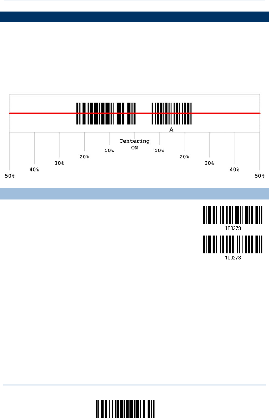
45
Update
Chapter 1
Understandin
g
t
he Barcode Scanner
1.13 EFFECTIVE DECODING AREA
By default, the effective decoding area is 100% covered by the sca nned area. However,
you may narrow down the decoding area to prevent reading the wrong barcode when a
number of barcodes are printed closely. The scanner will only read barcodes t hat appear
in the effective decoding area.
Read the barcode “Centering On” a nd specify the pe rcentage to narrow d own the
decoding area. For example, read “Left 10%” and then “Right 30%” for the scanner to
decode barcode “A” only.
1.13.1 POSITIONING WINDOW
Centering On
*Centering Off
46
Enter Setup
1663 Barcode Scanner User Guide
1.13.2 ADJUSTING WINDOW
Percentage for Left Half
*Left 50%
Left 40%
Left 30%
Left 20%
Left 10%
Percentage for Right Half
Right 10%
Right 20%
Right 30%
Right 40%
*Right 50%
47
Update
Chapter 1
Understandin
g
t
he Barcode Scanner
1.14 USE DIRECT USB CABLE
1663 supports Direct USB interface for charging the battery and/or sending data to the
host in memory mode. Refer to 1.2.2 Memory Mode.
Note: The scanner will not function when it is solely on USB power and without a battery
loaded.
1.14.1 DIRECT USB INTERFACE
When it is set to Memory Mode and connected to computer via the Direct USB cable, the
default output interface becomes “Direct USB Virt ual COM”, change it to “Direct USB
HID” if required.
For details on configuring the interface settings, refer to the following sections:
2.6 Direct USB HID
2.7 Direct USB Virtual COM
*Activate Direct
USB Virtual COM
Activate Direct
USB HID
1.14.2 DISABLE DIRECT USB INTERFACE
When connecting the USB cable to the scanner for chargi ng the battery, ensure the
“Disable Direct USB” barcode has been scanne d to avoid sending data to the host in
memory mode. In this mode the USB cable function will be charging the battery only.
Disable Direct USB

48
Enter Setup
1663 Barcode Scanner User Guide
1.15 PAGER BEEP DURATION
Paging function is only ac tivated when 1663 is in Po wer-Saving mode. 1663 can be
woken up via rec eiving any Bluetooth® status command by pressing a key on the host
keyboard. The buzzer will continuously sound two short high tone beeps until the power
key is pressed on the scanner o r the timeout is reached, and the scanner re-enters
power saving mode.
By default, the pager beep duration is 5 seconds. Specify a value, ranging from 0 to 15.
(0~15 sec.; 0= Disable)
Bluetooth® HID profile: Press any one of the following keys “Scroll Lock”, “Number
Lock” or “Caps Lock” on the host computer to trigger the waking up of 1663.
Bluetooth® SPP Profile: Any command sent u sing Bluetooth® SPP will trigger the
waking up of 1663.
Pager Beep Duration
0
~15 sec.
(*5 s)
1) Read the barcode above to specify the desired beep active time.
2) Read the “Decimal Value” barcode on page 219. For example, read “1” and “5” for the
pager beep function to be activated each 15 seconds after entering Power-Saving
mode.
3) Read the “Validate” barcode on the same page to complete this setting.

49
Update
Chapter 1
Understandin
g
t
he Barcode Scanner
1.16 TIME STAMP
Specify time stamp format added to the prefix or suffix of a data. Up to three settings
can be configured:
No Time Stamp
Add Time Stamp in front of data
Add Time Stamp to the end of data
If added in front of da ta, it means prior to th e prefix fi eld. Alternatively, to the end of
data.
No Time Stamp
*Disable
Add Time Stamp
in front of Data
Add Time Stamp
to the end of Data
1.16.1 DATE AND TIME SETTINGS
Read the barcode below to enable/disable Date and Time function.
Year Output
*Enable
Year Output
Disable
Month Output
*Enable
Month Output
Disable

50
Enter Setup
1663 Barcode Scanner User Guide
Date Output
*Enable
Date Output
Disable
Hour Output
*Enable
Hour Output
Diable
Minute Output
*Enable
Minute Output
Disalbe
Second Output
*Enable
Second Output
Diable

51
Update
Chapter 1
Understandin
g
t
he Barcode Scanner
Decoding Data and Time
Year Setup
Date Setup
Time Setup
1) Read the barcode above to apply time or date code separately, and follow steps 2~3.
2) Read the “Decimal Value” barcode on page 219 for the desired character string. Fo r
example:
Year: Read “2”, “0”, “1”, “1” for the year setting as year=2011.
Date: Read “1”, “1”, ”2”, “0” for the date setting as date=Nov.20.
Time: Read “1”, “8”, “5”, “9” for the time setting as time=18:59.
3) Read the “Validate” barcode for each setting on the same page.
1.16.2 SEPARATOR FOR DATE AND TIME
The Date and Time can be split with a pre-selected separator, for example, “/” as
YYYY/MM/DD or “:” as HH:MM:SS
Separator for
Date/Time
*“-”
Separator for
Month/Date
*“/”
Separator for
Hour/Minute
*“:”
1) Read the barcode above to apply separator to date or time separately, and fol low
steps 2~3.
2) Read the “Hexadecimal Value” barcode on page 220 for the desired character string.
For example, read “3” and “A” for the separator to split the data with character [:].
3) Read the “Validate” barcode on the same page to complete this setting.

52
Enter Setup
1663 Barcode Scanner User Guide
1.16.3 DATE FORMAT
The date fo rmat includes year, month a nd day. There are three ki nds of combinations
can be configured to specify Year, Month and Day:
Year/Month/Day (YYYY/MM/DD) or (YY/MM/DD)
Month/Day/Year (MM/DD/YYYY) or (MM/DD/YY)
Day/Month/Year (DD/MM/YYYY) or (DD/MM/YY)
*Year/Month/Day
Month/Day/Year
Day/Month/Year
About Year Format:
Year format can be pre-selected as 2-digit or 4- digit. For exampl e, if year format i s YYYY, the
output year is 2011 for 4-digit, alternatively is 11 for 2-digit.
*Year for 4-digit
Year for 2-digit

53
Update
Chapter 1
Understandin
g
t
he Barcode Scanner
1.17 HARDWARE RESET
1.17.1 RESTORE SYSTEM DEFAULTS
In addition to using the “Restore System Defaults” barcode, the following procedure
using key combinations, can be used to restore the system defaults during operation.
1) Hold down the [Power/Delete] key.
2) When the scanner responds with two short beeps (high tone), press the [Trigger] key
for 5 seconds. The scanner LED indicator becomes solid red and then goes off.
3) When the scanner responds with a long beep (high tone), release the keys. Its LED
indicator becomes solid red and goes off.
Note: The scanner will restart itself automatically.
1.17.2 RESET CONNECTION
When the output interface is Bluetooth® HID or Bluetooth® SPP Master, the scanner will
attempt to maintain an establ ished connection. To stop such re-connection, read the
“Reset Connection” or “Restore System Defaults” barcode to clear the current connection
record. Alternatively, use the key combination as described below to reset connection
during operation.
1) Hold down the [Trigger] key, a nd then pr ess the [Powe r/Delete] key for at l east 5
seconds.
2) The scanner will respond wi th two short beeps (hi gh tone). Wait until the scanner
responds with a long beep (high tone), release the keys.
Note: After resetting connection by hardware, the scanner will not restart itself
automatically. It will resume to its previous operation except no connection.

54
Enter Setup
1663 Barcode Scanner User Guide

55
Update
In order to establish a proper co nnection between host computer and the scanner, we
suggest following these instructions –
1) Install battery and hold down the [Power/Delete] key for 2 seconds to t urn on the
scanner.
2) Read the “Enter Setup” barcode to enter the configuration mode.
3) Read the associated barcodes to activate the desired interface.
See the following sections for output interfaces supported.
4) Read the barcodes for related settings.
5) Read the “Update” barcode to exit the configuration mode.
6) Turn on host computer or laptop and establish a WPAN connection with the scanner.
Refer to Chapter 3 – Setting up a WPAN Connection.
Note: (1) By default, the output interface is set to “Bluetooth® HID”.
(2) When set to Memory Mode and con nected to computer via the Direct US B
cable, the default output interface becomes “Direct USB Virtual COM”.
IN THIS CHAPTER
2.1 Bluetooth® HID......................................................... 56
2.2 Bluetooth® SPP Slave ................................................. 67
2.3 Bluetooth® SPP Master .............................................. 70
2.4 USB HID via 3610...................................................... 73
2.5 USB Virtual COM (CDC) via 3610 ................................. 83
2.6 Direct USB HID.......................................................... 85
2.7 Direct USB Virtual COM............................................... 95
Chapter 2
SELECTING OUTPUT INTERFACE

56
Enter Setup
1663 Barcode Scanner User Guide
2.1 BLUETOOTH® HID
For Bluetooth® HID, refer to Chapter 3 – Setting up a WPAN Connection for related
connection settings. The scanned data will be transmitted to the computer. To capture
the data run any text editor on your computer.
HID Settings Defaults
Keyboard Type PCAT (US)
Alphabet Layout Normal
Numeric Layout Normal
Capital Lock Type Normal
Capital Lock State Off
Alphabet Transmission Case-sensitive
Numeric Transmission Alphanumeric keypad
Inter-Character Delay 0 (ms)
Inter-Function Delay 0 (ms)
57
Update
Chapter 2
Selectin
g
Output Interface
2.1.1 ACTIVATE BLUETOOTH® HID & SELECT KEYBOARD TYPE
When Bluetooth® HID interface is activated, you will have to select a keyboard type to
complete this setting. By default, Bluetooth® HID is act ivated on the scanner, and the
keyboard type is set to PCAT (US).
Activate Bluetooth®
HID & Select Keyboard
Type…
1) Read the barcode above to activate Bluetooth® HID and select a keyboard type.
2) Read the “ Decimal Value” barcode on page 219. Refer to the tabl e below for the
number of desired keyboard type.
3) Read the “Validate” barcode on the same page to complete this setting.
Bluetooth® HID
The following keyboard types are supported —
No. Keyboard Type No.
Keyboard Type
64 PCAT (US) 72 PCAT (Spanish)
65 PCAT (French) 73 PCAT (Portuguese)
66 PCAT (German) 74 PS55 A01-2 (Japanese)
67 PCAT (Italy) 75 User-defined table
68 PCAT (Swedish) 76 PCAT (Turkish)
69 PCAT (Norwegian) 77 PCAT (Hungarian)
70 PCAT (UK) 78 PCAT (Swiss German)
71 PCAT (Belgium) 79 PCAT (Danish)

58
Enter Setup
1663 Barcode Scanner User Guide
2.1.2 RESET CONNECTION
For Bluetooth® HID, you can only have the scanner connected to one computer at a time.
If you want to connect the scanner to another host, you must read the “Reset
Connection” barcode so t hat the current connection record w ill be cleared. Then, the
scanner will restart itself automatically. Go th rough the process in 3.2.3 Connect to
Dongle to establish a new connection.
Refer to 1.17 Hardware Reset.
Reset Connection
Note: The “Restore System Defaults” barcode will also clear the current connection
record.

59
Update
Chapter 2
Selectin
g
Output Interface
2.1.3 KEYBOARD SETTINGS
Alphabet Layout
Numeric Layout
Capital Lock Type
Capital Lock Setting
Alphabet Transmission
Numeric Transmission
Note: Bluetooth® HID does not support these f unctions on PDAs – (1) Capital Lock
Setting: Auto Detection (2) Numeric Transmission: Numeric Keys
Alphabet Layout
By default, the alphabet layout is set to normal mode, also known as the st andard English layout.
Select French or German keyboard layout if necessary. The sc anner will make adjustm ents when
sending the "A", "Q", "W", "Z", "Y", and "M" characters according to this setting.
*Normal
AZERTY
QWERTZ
Note: This setting only works when the keyboard type selected is US k eyboard, such as
PCAT (US). The Alphabet Layout and Numeric Layout setting must match your
keyboard.

60
Enter Setup
1663 Barcode Scanner User Guide
US Keyboard Style – Normal
QWERTY layout, which is normally used in western countries.
Select “Lower Row” for the “Numeric Layout” setti ng for the upper row is for spec ial
characters.
French Keyboard Style – AZERTY
French layout; see below for French Keyboard Style.
Select “Upper Row” for the “Numeric Layout” setti ng for th e lower row i s for special
characters.
German Keyboard Layout – QWERTZ
German layout; see below for German Keyboard Style.
Select “Lower Row” for the “Numeric Layout” setti ng for the upper row is for spec ial
characters.
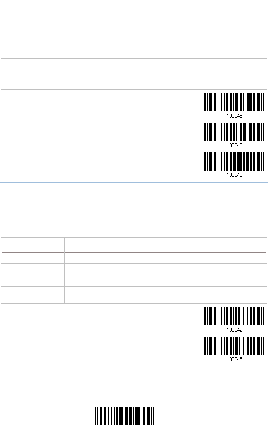
61
Update
Chapter 2
Selectin
g
Output Interface
Numeric Layout
Select a proper l ayout that matches the al phabet layout. The scanner will make a djustments
according to this setting.
Options Description
Normal Depends on the [Shift] key or [Shift Lock] setting
Lower Row For QWERTY or QWERTZ keyboard
Upper Row For AZERTY keyboard
*Normal
Upper Row
Lower Row
Note: This setting is to be used with the Character Substitution setting when support for
certain keyboard types (languages) is unavailable but required.
Capital Lock Type & Setting
In order to send the alphabet with correct case, the scanner needs to know the status of Caps Lock
on the keyboard. Incorrect settings may result in reversed case of the alphabet being transmitted.
Cap Lock Type Description
Normal Normal type
Capital Lock When enabled, the keys of alphabetic characters will be i nterpreted as
capital letters. However, this does not affect the n umber or punctuati on
keys.
Shift Lock When enabled, the keys of alphabetic characters will be i nterpreted as
capital letters. In addition, this affects the number or punctuation keys.
*Normal
Shift Lock
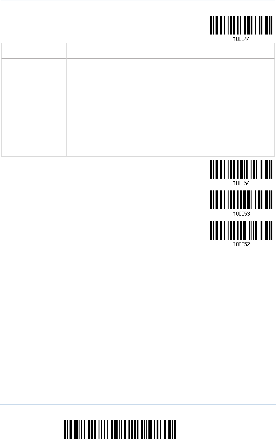
62
Enter Setup
1663 Barcode Scanner User Guide
Capital Lock
Capital Lock State Description
Capital Lock OFF Assuming that the status of Caps Lock on t he keyboard i s OFF,
transmitted characters a re exactly the same as in the barc ode (when
"case-sensitive" is selected for Alphabet Transmission).
Capital Lock ON Assuming that the status of Caps Lock on the keyboard is ON, transmitted
characters are exactly the same as i n the barcode (when "case-sensitive"
is selected for Alphabet Transmission).
Refer to the Capital Lock Type above.
Auto Detection
(Suggested use for
most applications)
The scanner will automatically detect the status of Caps Lock on the
keyboard before data i s transmitted; transmitted characters are exactly
the same a s in the barcode (when "case-sensitive" is selected for
Alphabet Transmission).
This setting is not supported on PDAs.
Auto Detect
Capital Lock ON
*Capital Lock OFF
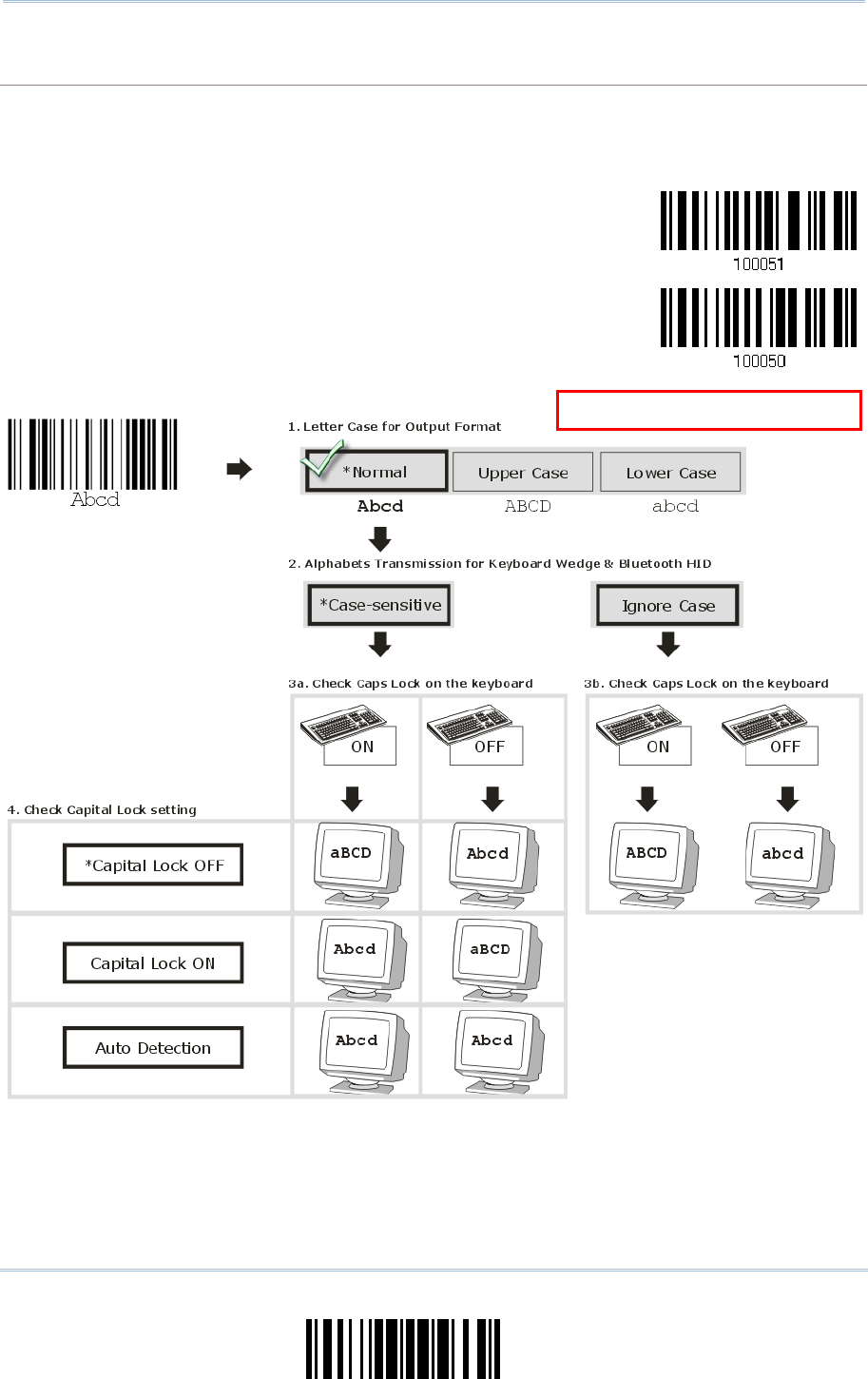
63
Update
Chapter 2
Selectin
g
Output Interface
Alphabet Transmission
By default, the alphabet transmission is case-sensitive, meaning that th e alphabet will be
transmitted according to the original case, the status of Caps Lock on the keyboard, as well as the
Capital Lock setting. Select [Ignore Case] to have alphabet transmitted according to the status of
Caps Lock on the keyboard only.
Ignore Case
*Case-sensitive
R
efer to 5.1 Letter Case.
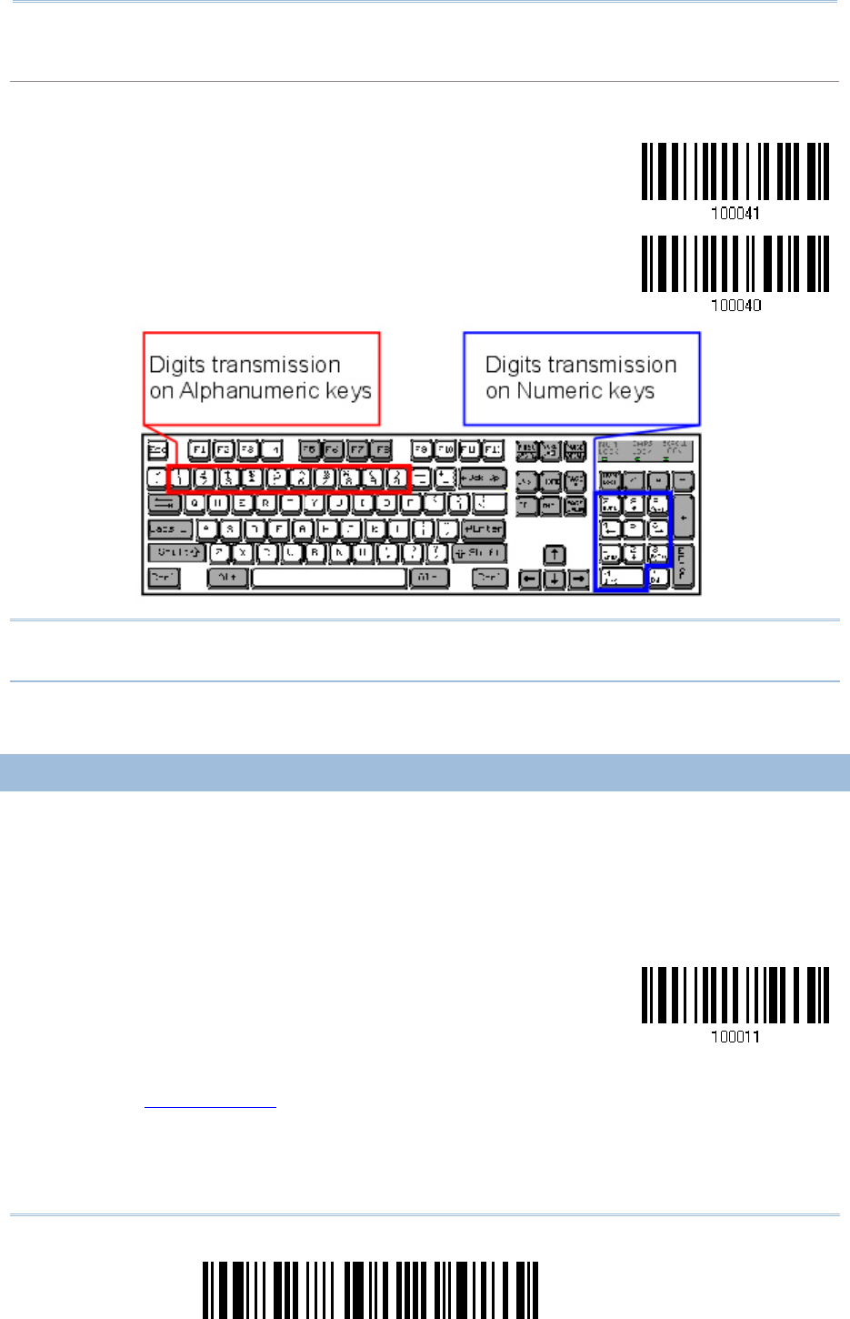
64
Enter Setup
1663 Barcode Scanner User Guide
Numeric Transmission
By default, the alphanumeric keypad is used for transmitting digits. Select “Numeric Keypad” if you
wish to use the keys on the numeric keypad.
Numeric Key
*Alphanumeric Key
Note: If you sel ect “Numeric Keypad”, t he Num Lo ck status of the p hysical keyboard
should be “ON”. This setting is not supported on PDAs.
2.1.4 INTER-CHARACTER DELAY
By default, the inter-character delay i s set to zero. Specify a value, ranging from 0 t o
254 in units of millis econds, to match the computer response time of the keyboard
interface. Such delay time is inserted between every c haracter being tra nsmitted. The
longer the delay time is, the slower the transmission speed will be.
Inter-Character
Delay… (*0~254)
1) Read the barcode above to specify the inter-character delay.
2) Read the “Decimal Value” barcode on page 219 for the desired inter-character delay
(in milliseconds).
3) Read the “Validate” barcode on the same page to complete this setting.

65
Update
Chapter 2
Selectin
g
Output Interface
2.1.5 INTER-FUNCTION DELAY
By default, the inter-function delay is set to zero. Specify a value, ranging from 0 to 254
in units of milliseconds, to match the computer response time of the keyboard interface.
Such delay time is inserted be tween every function code (0x01 ~ 0 x1F) being
transmitted. The longer the delay time is, the slower the transmission speed will be.
Inter-Function
Delay… (*0~254)
1) Read the barcode above to specify the inter-function delay.
2) Read the “Decimal Value” barcode on page 219 for the desired inter-function delay (in
milliseconds).
3) Read the “Validate” barcode on the same page to complete this setting.
66
Enter Setup
1663 Barcode Scanner User Guide
2.1.6 HID CHARACTER TRANSMIT MODE
By default, HID i nterface sends data to the host i n batch. You may read the “By
Character” barcode to process data one character at a time.
*Batch Processing
By Character
Note: “By Character” transmit mode is required when working with iPhone or iPad.
2.1.7 SPECIAL KEYBOARD FEATURE
By default, the special keyboard feature is based on the factory definition. You can decide
whether to apply the special keyboard feature. Refer to Keyboard Wedge Table.
*Apply
Bypass
2.1.8 KEYPAD SUPPORT FOR IPHONE/IPAD
When the scanner has been successfully connected to iPhone or iPad for data collection,
the onscreen keypad of iPhone or iPad will disappear. Read the “Use POWER Key to Show
or Hide Keypad” barcod e in advance. Then, it will allow pressing the [Power/Delete] key
to show or hide the onscreen keypad.
*Normal

67
Update
Chapter 2
Selectin
g
Output Interface
Use POWER Key to
Show or Hide Keypad
In addition to using the [Power/Delete] key, you may also show or hide the keypad by
reading the following barcode.
Show or Hide Keypad
Note: This function only works for
(1) iPhone 4 and 3GS version 4.1 or later, and (2) iPad version 4.2 or later.
2.1.9 SIMPLE PAIRING FOR IPHONE/IPAD
The required windo w of pairing passcode is always po p-up when you are using a
Bluetooth® connection to iPhone or iPad. Scan the barcode below to enable Bluetooth®
simple pairing for iOS so that the passcode required window will not be appeare d during
a connection. You can connect to iPhone/iPad more quickly. By def ault, this function is
set to Disable.
*Disable
Enable
Note: Simple pairing only supports to the device with Bluetooth® v2.1 or later.

68
Enter Setup
1663 Barcode Scanner User Guide
2.2 BLUETOOTH® SPP SLAVE
For Bluetooth® SPP Slave, refer to Chapter 3 – Setting up a WPAN Connection for related
connection settings.
2.2.1 ACTIVATE BLUETOOTH® SPP SLAVE MODE
This is SPP Slave Mode.
Activate Bluetooth®
SPP, Slave Mode
2.2.2 INTER-FUNCTION DELAY
By default, the inter-function delay is set to zero. Specify a value, ranging from 0 to 254
in units of milliseconds, to match the computer response time of the keyboard interface.
Such delay time is inserted be tween every function code (0x01 ~ 0 x1F) being
transmitted. The longer the delay time is, the slower the transmission speed will be.
Inter-Function
Delay… (*0~254)
1) Read the barcode above to specify the inter-function delay.
2) Read the “Decimal Value” barcode on page 219 for the desired inter-function delay (in
milliseconds).
3) Read the “Validate” barcode on the same page to complete this setting.
69
Update
Chapter 2
Selectin
g
Output Interface
2.2.3 ACK/NAK TIMEOUT
By default, the scanner sends data to the host without waiting for an ACK/NAK response
before sending more data. Specify a value, ranging from 1 to 99 in units of 0.1 second. If
no response within the specified period of time, the scanner will attempt to send the
same data two more t imes. If al l attempts fail without any notification, data l oss will
occur.
ACK/NAK Time-out
after … (*0~99)
1) Read the barcode above to specify the time interval for the scanner to send data and
wait for a response from the host.
2) Read the “Decimal Value” barcode on page 219. For example, read “1” and “0” for the
scanner to automatically shut down after being idle for 1 second.
3) Read the “Validate” barcode on the same page to complete this setting.
ACK/NAK Error Beep
Enable Error Beep
*Disable Error Beep
Note: We suggest enabling the error beep so that you will be notified of such data loss
and have the scanner re-read data.
70
Enter Setup
1663 Barcode Scanner User Guide
2.3 BLUETOOTH® SPP MASTER
As a SP P master device, the scanner will be able t o resume connection with the host
upon powering on again, as long as the host application is running. If the scanner fails to
resume connection, it will try every 5 seconds to re-connect to the host unless you read
the “Reset Connection” or “Restore System Defaults” barcode.
For Bluetooth® SPP Master, refer 3.2.2 Configure Related Settings for related connection
settings.
Note: In SPP Master Mode, scanner has to connect within the specified period of time (2
minutes by default). During the connection, the scanner will enter into idle mode
to save power. It will automatically turn off when the time is u p. Refer to 1.1.3
Auto Power Off & Power-Saving.
2.3.1 ACTIVATE BLUETOOTH® SPP MASTER MODE
This is SPP Master Mode.
Activate Bluetooth®
SPP, Master Mode
How to connect with the target device?
Produce two setup barcodes for the target SPP slave device, just like what we do for 3610.
“Set Connection”
“MAC ID”
Note: The “MAC ID” barcode must have a prefix of two characters, either “0x” or “0X”,
followed by the real MAC address of the target device.
Usage:
1) Read the “Activate Bluetooth® SPP, Master Mode” barcode above and barcodes for connection
settings, such as authenti cation and preset PI N. Skip this step i f no connecti on settings are
desired.
2) Read the “Set Connection” and “MA C ID” barcodes. The scann er will respond with one bee p
upon reading each of the barcodes.
Set Connection
P
refix “0X” to target MAC address
71
Update
Chapter 2
Selectin
g
Output Interface
Note: Read the “Set Connection” barcode first, and then the “MAC ID” barcode within 10
seconds.
Instead of producing the “MAC ID” barcode, you may read the setup barcodes for entering the MAC
address.
Read the “Abort” barcode to cancel the operation at any time while reading setup barcodes for
the MAC address. If the MAC address has not b een completed yet, reading the “V alidate”
barcode can cancel the operation as well.
Enter MAC ID in
Hexadecimal…
Usage:
1) Read the barcode above.
2) Read the “Hexadecimal Value” barcode on page 220 for the desired MAC address.
3) Read the “Validate” barcode on the same page to complete this setting.
Exit SPP Master Mode
To stop such re-connection, read “Reset Connection” or “Restore System Defaults” barcode so that
the current connection record (= MAC ID) will be cleared. Then, the sca nner will restart i tself
automatically. Go throug h the process i n 3.2.3 Connect to Dongle to e stablish a new WPAN
connection.
Reset Connection
2.3.2 INTER-FUNCTION DELAY
By default, the inter-function delay is set to zero. Specify a value, ranging from 0 to 254
in units of milliseconds, to match the computer response time of the keyboard interface.
Such delay time is inserted be tween every function code (0x01 ~ 0 x1F) being
transmitted. The longer the delay time is, the slower the transmission speed will be.
Inter-Function
Delay… (*0~254)
1) Read the barcode above to specify the inter-function delay.
2) Read the “Decimal Value” barcode on page 219 for the desired inter-function delay (in
milliseconds).
3) Read the “Validate” barcode on the same page to complete this setting.
72
Enter Setup
1663 Barcode Scanner User Guide
2.3.3 ACK/NAK TIMEOUT
By default, the scanner sends data to the host without waiting for an ACK/NAK response
before sending more data. Specify a value, ranging from 1 to 99 in units of 0.1 second. If
no response within the specified period of time, the scanner will attempt to send the
same data two more t imes. If al l attempts fail without any notification, data l oss will
occur.
ACK/NAK Time-out
after … (*0~99)
1) Read the barcode above to specify the time interval for the scanner to send data and
wait for a response from the host.
2) Read the “Decimal Value” barcode on page 219. For example, read “1” and “0” for the
scanner to automatically shut down after being idle for 1 second.
3) Read the “Validate” barcode on the same page to complete this setting.
ACK/NAK Error Beep
Enable Error Beep
*Disable Error Beep
Note: We suggest enabling the error beep so that you will be notified of such data loss
and have the scanner re-read data.
2.3.4 SWITCH BETWEEN MASTER/SLAVE MODE
After the scanner has established a connection as a SPP sl ave device, you may r ead the
“Activate Bluetooth® SPP, Master Mode” setup barcode t o switch to SPP Master Mode.
This will result in easy and reliable re-connection, just like connecting with 3610.

73
Update
Chapter 2
Selectin
g
Output Interface
2.4 USB HID VIA 3610
For USB HID, connect 3610 to the USB port of PC, and then connect the scanner to 3610.
The scanned data will be transmitted to the computer. To capture the data run any text
editor on your computer.
HID Settings Defaults
Keyboard Type PCAT (US)
Numeric Layout Normal
Capital Lock Type Normal
Capital Lock State Off
Alphabet Transmission Case-sensitive
Numeric Transmission Alphanumeric keypad
Inter-Character Delay 0 (ms)
Inter-Function Delay 0 (ms)

74
Enter Setup
1663 Barcode Scanner User Guide
2.4.1 ACTIVATE USB HID & SELECT KEYBOARD TYPE
When USB HID interface is activated, you will have to select a keyboard type to complete
this setting.
Activate
3610 USB HID & Select
Keyboard Type…
1) Read the barcode above to activate USB HID and select a keyboard type.
2) Read the “ Decimal Value” barcode on page 219. Refer to the tabl e below for the
number of desired keyboard type.
3) Read the “Validate” barcode on the same page to complete this setting.
USB HID
The following keyboard types are supported —
No. Keyboard Type No.
Keyboard Type
64 PCAT (US) 72 PCAT (Spanish)
65 PCAT (French) 73 PCAT (Portuguese)
66 PCAT (German) 74 PS55 A01-2 (Japanese)
67 PCAT (Italy) 75 User-defined table
68 PCAT (Swedish) 76 PCAT (Turkish)
69 PCAT (Norwegian) 77 PCAT (Hungarian)
70 PCAT (UK) 78 PCAT (Swiss German)
71 PCAT (Belgium) 79 PCAT (Danish)

75
Update
Chapter 2
Selectin
g
Output Interface
2.4.2 KEYBOARD SETTINGS
Alphabet Layout
Numeric Layout
Capital Lock Type
Capital Lock Setting
Alphabet Transmission
Numeric Transmission
Alphabet Layout
By default, the alphabet layout is set to normal mode, also known as the st andard English layout.
Select French or German keyboard layout if necessary. The sc anner will make adjustm ents when
sending the "A", "Q", "W", "Z", "Y", and "M" characters according to this setting.
*Normal
AZERTY
QWERTZ
Note: This setting only works when the keyboard type selected is US k eyboard, such as
PCAT (US). The Alphabet Layout and Numeric Layout setting must match your
keyboard.

76
Enter Setup
1663 Barcode Scanner User Guide
US Keyboard Style – Normal
QWERTY layout, which is normally used in western countries.
Select “Lower Row” for the “Numeric Layout” setti ng for the upper row is for spec ial
characters.
French Keyboard Style – AZERTY
French layout; see below for French Keyboard Style.
Select “Upper Row” for the “Numeric Layout” setti ng for th e lower row i s for special
characters.
German Keyboard Layout – QWERTZ
German layout; see below for German Keyboard Style.
Select “Lower Row” for the “Numeric Layout” setti ng for the upper row is for spec ial
characters.
77
Update
Chapter 2
Selectin
g
Output Interface
Numeric Layout
Select a proper l ayout that matches the al phabet layout. The scanner will make a djustments
according to this setting.
Options Description
Normal Depends on the [Shift] key or [Shift Lock] setting
Lower Row For QWERTY or QWERTZ keyboard
Upper Row For AZERTY keyboard
*Normal
Upper Row
Lower Row
Note: This setting is to be used with the Character Substitution setting when support for
certain keyboard types (languages) is unavailable but required.

78
Enter Setup
1663 Barcode Scanner User Guide
Capital Lock Type & Setting
In order to send the alphabet with correct case, the scanner needs to know the status of Caps Lock
on the keyboard. Incorrect settings may result in reversed case of the alphabet being transmitted.
Cap Lock Type Description
Normal Normal type
Capital Lock When enabled, the keys of alphabetic characters will be i nterpreted as
capital letters. However, this does not affect the n umber or punctuati on
keys.
Shift Lock When enabled, the keys of alphabetic characters will be i nterpreted as
capital letters. In addition, this affects the number or punctuation keys.
*Normal
Shift Lock
Capital Lock
Capital Lock State Description
Capital Lock OFF Assuming that the status of Caps Lock on t he keyboard i s OFF,
transmitted characters a re exactly the same as in the barc ode (when
"case-sensitive" is selected for Alphabet Transmission).
Capital Lock ON Assuming that the status of Caps Lock on the keyboard is ON, transmitted
characters are exactly the same as i n the barcode (when "case-sensitive"
is selected for Alphabet Transmission).
Refer to the Capital Lock Type above.
Auto Detection
(suggested use for
most applications)
T
he scanner will automatically detect the status of Caps Lock on the
keyboard before data i s transmitted; transmitted characters are exactly
the same a s in the barcode (when "case-sensitive" is selected for
Alphabet Transmission).
Auto Detect
Capital Lock ON

79
Update
Chapter 2
Selectin
g
Output Interface
*Capital Lock OFF
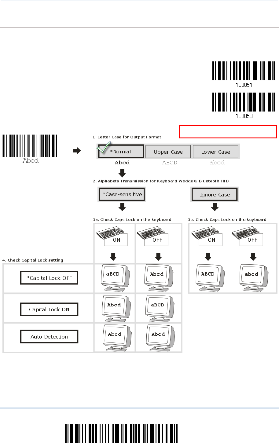
80
Enter Setup
1663 Barcode Scanner User Guide
Alphabet Transmission
By default, the alphabet transmission is case-sensitive, meaning that th e alphabet will be
transmitted according to the original case, the status of Caps Lock on the keyboard, as well as the
Capital Lock setting. Select [Ignore Case] to have alphabet transmitted according to the status of
Caps Lock on the keyboard only.
Ignore Case
*Case-sensitive
R
efer to 5.1 Letter Case.
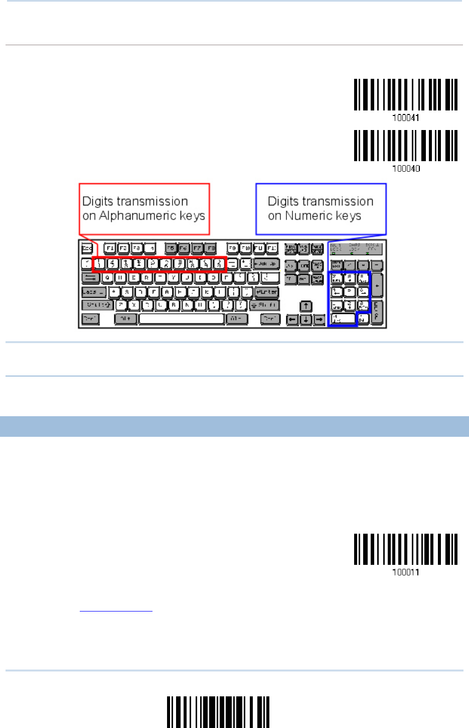
81
Update
Chapter 2
Selectin
g
Output Interface
Numeric Transmission
By default, the alphanumeric keypad is used for transmitting digits. Select “Numeric Keypad” if you
wish to use the keys on the numeric keypad.
Numeric Key
*Alphanumeric Key
Note: If you sel ect “Numeric Keypad”, t he Num Lo ck status of the p hysical keyboard
should be "ON".
2.4.3 INTER-CHARACTER DELAY
By default, the inter-character delay i s set to zero. Specify a value, ranging from 0 t o
254 in units of millis econds, to match the computer response time of the keyboard
interface. Such delay time is inserted between every c haracter being tra nsmitted. The
longer the delay time is, the slower the transmission speed will be.
Inter-Character
Delay… (*0~254)
1) Read the barcode above to specify the inter-character delay.
2) Read the “Decimal Value” barcode on page 219 for the desired inter-character delay
(in milliseconds).
3) Read the “Validate” barcode on the same page to complete this setting.
82
Enter Setup
1663 Barcode Scanner User Guide
2.4.4 INTER-FUNCTION DELAY
By default, the inter-function delay is set to zero. Specify a value, ranging from 0 to 254
in units of milliseconds, to match the computer response time of the keyboard interface.
Such delay time is inserted be tween every function code (0x01 ~ 0 x1F) being
transmitted. The longer the delay time is, the slower the transmission speed will be.
Inter-Function
Delay… (*0~254)
1) Read the barcode above to specify the inter-function delay.
2) Read the “Decimal Value” barcode on page 219 for the desired inter-function delay (in
milliseconds).
3) Read the “Validate” barcode on the same page to complete this setting.
2.4.5 HID CHARACTER TRANSMIT MODE
By default, HID i nterface sends data to th e host in batch. Read the “By Character”
barcode will send the data one character at a time.
*Batch Processing
By Character
2.4.6 SPECIAL KEYBOARD FEATURE
By default, the special keyboard feature is based on the factory definition. You can decide
whether to apply the special keyboard feature. Refer to Keyboard Wedge Table.
*Apply
Bypass
83
Update
Chapter 2
Selectin
g
Output Interface
2.5 USB VIRTUAL COM (CDC) VIA 3610
Connect 3610 to the USB port of PC, and then connect the scanner to 3610. You may run
HyperTerminal.exe on the comput er to view and capture the data transmission from the
scanner.
2.5.1 ACTIVATE USB VIRTUAL COM
Activate 3610
USB Virtual COM
Note: If you are using USB Virtual COM for the first time, you must install its driver from
the CD-ROM. Driver version 5.4 or later is required. Please remove older versions
before installing new ones!
2.5.2 ACTIVATE USB VIRTUAL COM_CDC
Activate 3610
USB Virtual COM_CDC
Note: If you are using USB Virtual COM_CDC for the first time, you must install its driver
from the CD-ROM. To activate the CDC driver, 3610’s firmware version must b e
2.0 or later.
2.5.3 INTER-FUNCTION DELAY
By default, the inter-function delay is set to zero. Specify a value, ranging from 0 to 254
in units of milliseconds, to match the computer response time of the keyboard interface.
Such delay time is inserted be tween every function code (0x01 ~ 0 x1F) being
transmitted. The longer the delay time is, the slower the transmission speed will be.
Inter-Function
Delay… (*0~254)
1) Read the barcode above to specify the inter-function delay.
2) Read the “Decimal Value” barcode on page 219 for the desired inter-function delay (in
milliseconds).
3) Read the “Validate” barcode on the same page to complete this setting.

84
Enter Setup
1663 Barcode Scanner User Guide
2.5.4 ACK/NAK TIMEOUT
By default, the scanner sends data to the host without waiting for an ACK/NAK response
before sending more data. Specify a value, ranging from 1 to 99 in units of 0.1 second. If
no response within the specified period of time, the scanner will attempt to send the
same data two more t imes. If al l attempts fail without any notification, data l oss will
occur.
ACK/NAK Time-out
after … (*0~99)
1) Read the barcode above to specify the time interval for the scanner to send data and
wait for a response from the host.
2) Read the “Decimal Value” barcode on page 219. For example, read “1” and “0” for the
scanner to automatically shut down after being idle for 1 second.
3) Read the “Validate” barcode on the same page to complete this setting.
ACK/NAK Error Beep
Enable Error Beep
*Disable Error Beep
Note: We suggest enabling the error beep so that you will be notified of such data loss
and have the scanner re-read data.
85
Update
Chapter 2
Selectin
g
Output Interface
2.6 DIRECT USB HID
1663 supports “Direct” USB HID interface for memory mode. Use the provided USB cable
to connect 1663 to the USB port of PC. Run any text editor on a co mputer to view and
capture the scanned d ata being transm itted to the com puter. Refer to 1.2.2 Memory
Mode.
HID Settings Defaults
Keyboard Type HID PCAT (US)
Numeric Layout Normal
Capital Lock Type Normal
Capital Lock State OFF
Alphabet Transmission Case Sensitive
Numeric Transmission Alphanumeric Keypad
Inter-Character Delay 0 (ms)
Inter-Function Delay 0 (ms)
86
Enter Setup
1663 Barcode Scanner User Guide
2.6.1 ACTIVATE USB HID & SELECT KEYBOARD TYPE
When USB HID interface is activa ted, please select a keyboard ty pe to compl ete this
setting.
Activate
Direct USB HID &
Select Keyboard
Type…
1) Read the barcode above to activate USB HID and select a keyboard type.
2) Read the “Decimal Value” barcode page 219 . Refer to the table below for the number
of desired keyboard type.
3) Read the “Validate” barcode on the same page to complete this setting.
USB HID
By default, the keyboard type is set to PCAT (US). The following keyboard types are supported —
No. Keyboard Type No.
Keyboard Type
64 PCAT (US) 72 PCAT (Spanish)
65 PCAT (French) 73 PCAT (Portuguese)
66 PCAT (German) 74 PS55 A01-2 (Japanese)
67 PCAT (Italy) 75 User-defined table
68 PCAT (Swedish) 76 PCAT (Turkish)
69 PCAT (Norwegian) 77 PCAT (Hungarian)
70 PCAT (UK) 78 PCAT (Swiss German)
71 PCAT (Belgium) 79 PCAT (Danish)

87
Update
Chapter 2
Selectin
g
Output Interface
2.6.2 KEYBOARD SETTINGS
Alphabet Layout
Numeric Layout
Capital Lock Type
Capital Lock Setting
Alphabet Transmission
Numeric Transmission
Alphabet Layout
By default, the alphabet layout is set to normal mode, also known as the st andard English layout.
Select French or German keyboard layout if necessary. The sc anner will make adjustm ents when
sending the "A", "Q", "W", "Z", "Y", and "M" characters according to this setting.
*Normal
AZERTY
QWERTZ
Note: This setting only works when the keyboard type selected is US k eyboard, such as
PCAT (US). The Al phabet Layout and Numeric Layout setting must match using
keyboard.
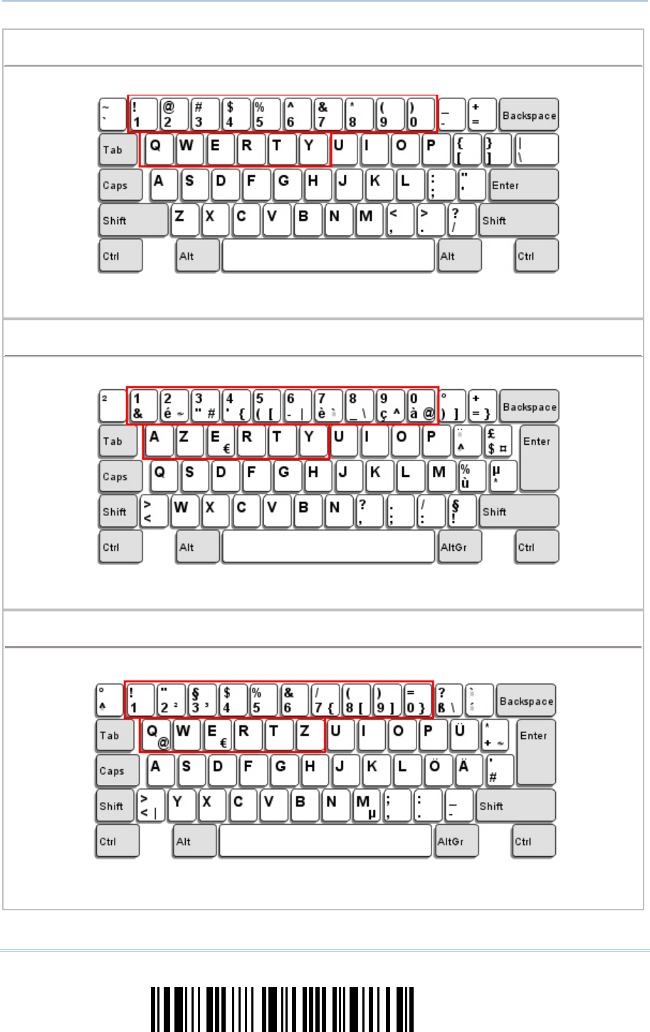
88
Enter Setup
1663 Barcode Scanner User Guide
US Keyboard Style – Normal
QWERTY layout, which is normally used in western countries.
Select “Lower Row” for the “Numeric Layout” setti ng for the upper row is for spec ial
characters.
French Keyboard Style – AZERTY
French layout; see below for French Keyboard Style.
Select “Upper Row” for the “Numeric Layout” setti ng for th e lower row i s for special
characters.
German Keyboard Layout – QWERTZ
German layout; see below for German Keyboard Style.
Select “Lower Row” for the “Numeric Layout” setti ng for the upper row is for spec ial
characters.

89
Update
Chapter 2
Selectin
g
Output Interface
Numeric Layout
Select a proper l ayout that matches the al phabet layout. The scanner will make a djustments
according to this setting.
Options Description
Normal Depends on the [Shift] key or [Shift Lock] setting
Lower Row For QWERTY or QWERTZ keyboard
Upper Row For AZERTY keyboard
*Normal
Upper Row
Lower Row
Note: This setting is to be used with the Character Substitution setting when support for
certain keyboard types (languages) is unavailable but required.
90
Enter Setup
1663 Barcode Scanner User Guide
Capital Lock Type & Setting
In order to send the alphabet with correct case, the scanner needs to know the status of Caps Lock
on the keyboard. Incorrect settings may result in reversed case of the alphabet being transmitted.
Cap Lock Type Description
Normal Normal type
Capital Lock When enabled, the keys of alphabetic characters will be i nterpreted as
capital letters. However, this does not affect the n umber or punctuati on
keys.
Shift Lock When enabled, the keys of alphabetic characters will be i nterpreted as
capital letters. In addition, this affects the number or punctuation keys.
*Normal
Shift Lock
Capital Lock
Capital Lock State Description
Capital Lock OFF Assuming that the status of Caps Lock on t he keyboard i s OFF,
transmitted characters a re exactly the same as in the barc ode (when
"case-sensitive" is selected for Alphabet Transmission).
Capital Lock ON Assuming that the status of Caps Lock on the keyboard is ON, transmitted
characters are exactly the same as i n the barcode (when "case-sensitive"
is selected for Alphabet Transmission).
Refer to the Capital Lock Type above.
Auto Detection
(suggested use for
most applications)
T
he scanner will automatically detect the status of Caps Lock on the
keyboard before data i s transmitted; transmitted characters are exactly
the same a s in the barcode (when "case-sensitive" is selected for
Alphabet Transmission).
Auto Detect
Capital Lock ON

91
Update
Chapter 2
Selectin
g
Output Interface
*Capital Lock OFF

92
Enter Setup
1663 Barcode Scanner User Guide
Alphabet Transmission
By default, the alphabet transmission is case-sensitive, meaning that th e alphabet will be
transmitted according to the original case, the status of Caps Lock on the keyboard, as well as the
Capital Lock setting. Select [Ignore Case] to have alphabet transmitted according to the status of
Caps Lock on the keyboard only.
Ignore Case
*Case-sensitive
R
efer to 5.1 Letter Case.

93
Update
Chapter 2
Selectin
g
Output Interface
Numeric Transmission
By default, the alphanumeric keypad is used for transmitting numerics. Select “Numeric Keypad” if
want to use the keys on the numeric keypad.
Numeric Key
*Alphanumeric Key
Note: If selecting “Numeric Keypad”, the Num Lock status of the physical keyboard
should be "ON".
2.6.3 INTER-CHARACTER DELAY
By default, the inter-character delay i s set to zero. Specify a value, ranging from 0 t o
254 in units of millis econds, to match the computer response time of the keyboard
interface. Such delay time is inserted between every c haracter being tra nsmitted. The
longer the delay time is, the slower the transmission speed will be.
Inter-Character
Delay… (*0~254)
1) Read the barcode above to specify the inter-character delay.
2) Read the “Decimal Value” barcode on page 219 for the desired inter-character delay
(in milliseconds).
3) Read the “Validate” barcode on the same page to complete this setting.
94
Enter Setup
1663 Barcode Scanner User Guide
2.6.4 INTER-FUNCTION DELAY
By default, the inter-function delay is set to zero. Specify a value, ranging from 0 to 254
in units of milliseconds, to match the computer response time of the keyboard interface.
Such delay time is inserted be tween every function code (0x01 ~ 0 x1F) being
transmitted. The longer the delay time is, the slower the transmission speed will be.
Inter-Function
Delay… (*0~254)
1) Read the barcode above to specify the inter-function delay.
2) Read the “Decimal Value” barcode on page 219 for the desired inter-function delay (in
milliseconds).
3) Read the “Validate” barcode on the same page to complete this setting.
2.6.5 HID CHARACTER TRANSMIT MODE
By default, HID interface sends data to the host in batch, or use the scanner to read the
“By Character” barcode to process data one character at a time.
*Batch Processing
By Character
2.6.6 SPECIAL KEYBOARD FEATURE
By default, the special keyboard feature is based on the factory definition. You can decide
whether to apply the special keyboard feature. Refer to Keyboard Wedge Table.
*Apply
Bypass
95
Update
Chapter 2
Selectin
g
Output Interface
2.7 DIRECT USB VIRTUAL COM
1663 supports “Direct” USB Virtual COM interf ace for memory mode. Use the p rovided
USB cable to connect 1663 to the USB port of PC. You may run HyperTerminal.exe on a
computer to view and capture the scanned data being transmitted to the computer. Refer
to 1.2.2 Memory Mode.
2.7.1 ACTIVATE USB VIRTUAL COM
*
Activate Direct USB
Virtual COM
Note: If using USB Virt ual COM for the first time, install its driver from the CD-ROM.
Driver version 5.4 or lat er is required. Please remo ve older v ersions before
installing new ones!
2.7.2 ACTIVATE USB VIRTUAL COM_CDC
*
Activate Direct USB
Virtual COM_CDC
Note: If using USB Virt ual COM_CDC for the first time, install its driver from the
CD-ROM.
2.7.3 INTER-FUNCTION DELAY
By default, the inter-function delay is set to zero. Specify a value, ranging from 0 to 254
in units of milliseconds, to match the computer response time of the keyboard interface.
Such delay time is inserted be tween every function code (0x01 ~ 0 x1F) being
transmitted. The longer the delay time is, the slower the transmission speed will be.
Inter-Function
Delay… (*0~254)
1) Read the barcode above to specify the inter-function delay.
2) Read the “Decimal Value” barcode on page 219 for the desired inter-function delay (in
milliseconds).
3) Read the “Validate” barcode on the same page to complete this setting.
96
Enter Setup
1663 Barcode Scanner User Guide
2.7.4 ACK/NAK TIMEOUT
By default, the scanner sends data to the host without waiting for an ACK/NAK response
before sending more data. Specify a value, ranging from 1 to 99 in units of 0.1 second. If
no response within the specified period of time, the scanner will attempt to send the
same data two more t imes. If al l attempts fail without any notification, data l oss will
occur.
ACK/NAK Time-out
after … (*0~99)
1) Read the barcode above to specify the time interval for the scanner to send data and
wait for a response from the host.
2) Read the “Decimal Value” barcode on page 219. For example, read “1” and “0” for the
scanner to automatically shut down after being idle for 1 second.
3) Read the “Validate” barcode on the same page to complete this setting.
ACK/NAK Error Beep
Enable Error Beep
*Disable Error Beep
Note: We suggest enabling the error beep so that data loss is notified and the scanner
re-read data.
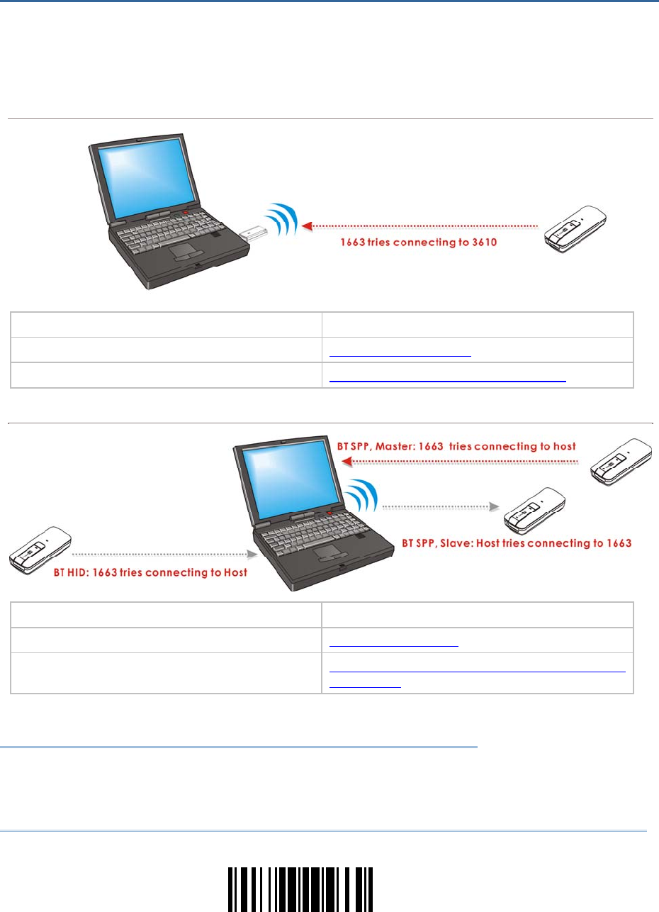
97
Update
The scanner can be configured to send data to a host computer wireless ly via the 3610
dongle, or to a notebook computer or PDA with Bluetooth® wireless technology. Upon
powering up, the scanner will be ready to establish a WPAN connection.
To establish a connection via 3610 after reading “Set Connection” and “Serial No.” barcodes …
Interface Option Reference
USB HID 2.4 USB HID via 3610
USB Virtual COM 2.5 USB Virtual COM (CDC) via 3610
To establish a connection via Bluetooth® dongle after pairing…
Interface Option Reference
Bluetooth® HID 2.1 Bluetooth® HID
Bluetooth® SPP 2.2 Bluetooth® SPP Slave, 2.3 Bluetooth®
SPP Master
IN THIS CHAPTER
3.1 Connecting via 3610 .................................................. 98
3.2 Connecting via Bluetooth® Dongle ...............................100
Chapter 3
SET UP A WPAN CONNECTION

98
Enter Setup
1663 Barcode Scanner User Guide
3.1 CONNECTING VIA 3610
By default, the interface of 3610 is set to “U SB HID”. You can have up to seven scanners
connected to one computer at the same time.
Note: If you are using USB Virtual COM for the first time, you must install its driver from
the CD-ROM. Driver version 5.4 or later is required. Please remove older versions!
3.1.1 CONNECT TO 3610
Connect any scanner to 3610 by reading the tw o labels at the back of 3610. The scanner
will respond with one beep upon reading each of the labels.
“Set Connection” label
“Serial Number” label
After reading these labels, the scanner will stay active for a specif ied period of t ime (2
minutes by default) trying to connect to the 3610 while its LED is flashing blue (On/Off
ratio 0.5 s: 0.5 s). Once con nected, the scanner will respond with three beeps ( tone
ascending from low to high), and the LED flashes blue (On/Off ratio 0.02 s: 3 s). When
out of range, the scanner will respond with three short beeps (tone descending from high
to low).
Read the “Set Connection” barcode first, an d then the “Serial Number” barcode. If the
“Set Connection” barcode on 3610 is illegible, try this one —
Set Connection
Note: The 3610 settings will overwrite the interface-related settings on the scanners that
are currently connected to 3610.
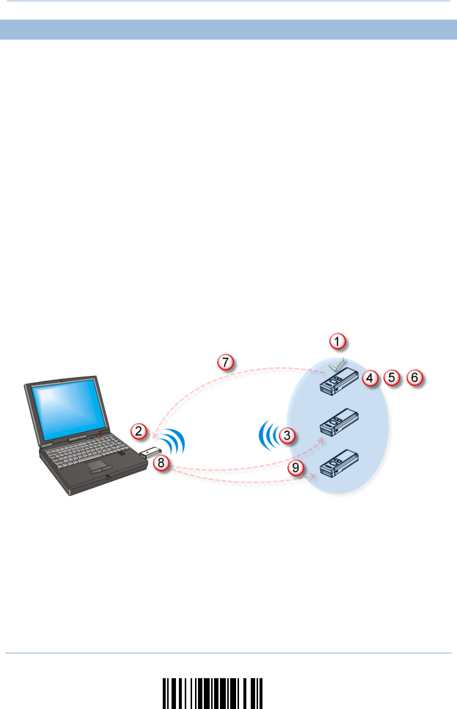
99
Update
Chapter 3
Set
up a WPAN Connection
3.1.2 CHANGE INTERFACE
If you want to change the communication interface of 3610, use o ne of the connected
scanners to configure the interface-related settings and the sca nner will pass the new
settings to 3610, whi ch will th en initialize and pass the se ttings to other connected
scanners.
1) Read the “Set Connection” and “Serial Number” barcodes at the back of 3610.
2) Within two minutes, connect 3610 to the USB port of PC. For USB Vi rtual COM, you
will need to install its driver first!
3) Scanners will connect to the computer via 3610.
4) Read the “Enter Setup” barcode to enter the configuration mode.
5) Read the desired interface barcode and configure its related settings –
“Activate USB HID & Select Keyboard Type”
“Activate USB Virtual COM”
6) Read the “Update” barcode to exit the configuration mode.
7) After the scanner resumes co nnection with 3610, it will pass the interface-r elated
settings to 3610.
8) Upon receipt of the new settings, 3610 will initialize itself.
9) Updated with new settings, 3610 will pass the settings to other connected scanners.

100
Enter Setup
1663 Barcode Scanner User Guide
3.2 CONNECTING VIA BLUETOOTH® DONGLE
3.2.1 CHANGE INTERFACE
Below is the procedure to confi gure the scanner before establishing a WPAN co nnection
via Bluetooth® dongle.
1) Read the “Enter Setup” barcode to enter the configuration mode.
2) Read the desired interface barcode –
“Activate Bluetooth® HID & Select Keyboard Type”
“Activate Bluetooth® SPP Slave Mode”
“Activate Bluetooth® SPP Master Mode”
3) Read the barcodes related to WP AN settings, such as Device Name Broadcasting,
Authentication & PIN Code, etc.
4) Read the “Update” barcode to exit the configuration mode.
5) The scanner will stay active for a specif ied period of time (2 minutes by default)
waiting for a connection request from the host (SPP Slave Mode) or trying to connect
to the host (HID or SPP Master Mode). Its CPU is running at full speed, and the LED is
flashing blue (On/Off ratio 0.5 s: 0.5 s).
Once connected, when out of range, the scanner will respond with three short beeps
(tone descending from high to low).
101
Update
Chapter 3
Set
up a WPAN Connection
3.2.2 CONFIGURE RELATED SETTINGS
Sniff Mode (Power-saving)
By default, this feature is enabl ed, meaning the scanner wi ll listen to the wi reless network at a
reduced rate.
*Enable
Disable
Note: When connecting more than two scanners to a notebo ok computer or PDA with
Bluetooth® wireless technology, we suggest that you disable the power-saving
setting for a more reliable connection.
Device Name Broadcasting
The scanner can be configured to hide itself from other devices equipped with Bluetooth® wireless
technology. Simply disable the device name broadcasting setting so that i t won’t be discovered by
any other computer or PDA. However, broadcasting must be enabled for establishing an initial
connection with the scan ner. For exampl e, disable device name broadcas ting after su ccessfully
connecting the scanner to WorkStati on1. Such connection will be mai ntained automatically unless
the scanner is removed from the paired device list (called unpairing) by WorkStation1 or any
changes made to auth entication and PIN code. If you want WorkStati on2 to connect to the
scanner, you have to enable device name broadcasting first.
*Enable
Disable
Note: By default, device name broadcasting is en abled (which is requ ired for initial
connection).
102
Enter Setup
1663 Barcode Scanner User Guide
Authentication
When any changes are made to authentication and PIN code on the scanner side, you will have t o
remove the scanner from the paired device list (called unpairing) and go through the whole process
to re-establish the connection.
The scanner allows up to 16 characters for a PIN code and provides two options for authentication:
Enable Authentication with Preset PIN
Read the “Use preset PIN” barcode, and change the preset PIN if necessary. This means you will
have to enter exactly the same string for your computer or PDA to connect to the scanner. If the
PIN or passkey is incorrect, any connecti on attempt will be turned down by the scanne r. See
step 8 in 3.2.3 Connect to Dongle.
1) Read the “Use preset PIN” barcode to enable authentication with a preset PIN.
Use Preset PIN
2) Read one of the barcodes to specify the PIN code, in decimal or hexadecimal.
By default, the PIN code is set to “0000”. Maximum 16 characters are allowed.
Enter PIN in
Hexadecimal …
Enter PIN in
Decimal…
3) Read the “ Decimal Value” barcode on page 219 or the “ Hexadecimal Value” barcode on
page 220 for the desired digits or character string.
Read the “Clear PIN Code” barcode first if you need to re-input the PIN code.
Clear PIN Code
4) Read the “Validate” barcode to complete this setting.
Enable Authentication with Random PIN or No Authentication
By default, it is set to “No PIN or use random PIN”, which depends on the setting of the target
device. (No PIN = No authentication.)
*
No PIN or
use random PIN
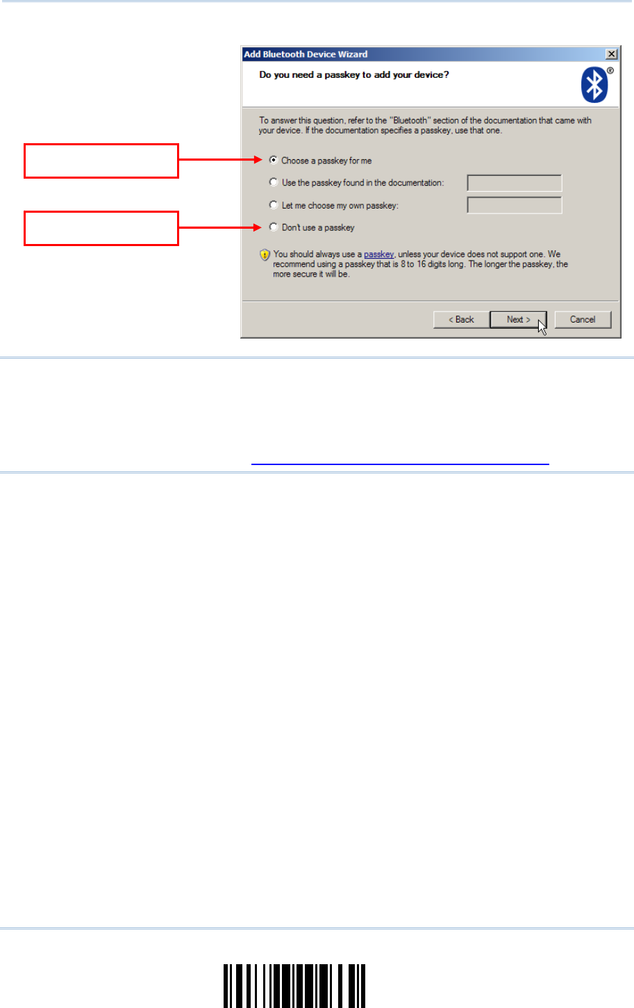
103
Update
Chapter 3
Set
up a WPAN Connection
Note: When using Bluetooth® HID, some device driver ma y not support pre-defined PIN
code for authentication. In this case, make sure you have the scanner set to “No
PIN or u se random PIN” before pairing. While pairing, the host PIN code will be
displayed on the com puter screen. Have the scanner read the s etup barcode
“Enter PIN Code in Decimal” or “ Enter PIN Code in Hexadecimal” to input the
matching PIN code. Refer to Disable Authentication or Use Random PIN.
Use random PIN
N
o PIN require
d
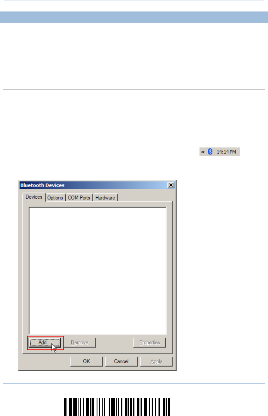
104
Enter Setup
1663 Barcode Scanner User Guide
3.2.3 CONNECT TO DONGLE
The procedure goes through associating devices for establ ishing a WPAN co nnection,
which is pretty much the same except for the software you are using. If your computer is
running Microsoft® Windows® XP (SP1 to SP3), Windows Vista® Service Pack 1 (SP1) and
Windows 7, y ou can use t he software support that Windows ® includes, or y ou can u se
the driver that the device manufacturer pr ovides. Now, l et’s try using the software
support that Windows® XP Service Pack 2 includes.
Bluetooth® HID Procedure
By default, Bluetooth® HID is activated on the scanner, and the keyboard type is set to PCAT (US).
When Bluetooth® HID is re-activated, you will have to select a keyboard type to complete this
setting.
The procedure is the same as for Bluetooth® SPP. Refer to steps 1~11 below.
Bluetooth® SPP Procedure
1) Turn on the Bluetooth® function on your computer, running Windows XP SP2.
2) Double-click the Bluetooth® icon from the lower right of the taskbar.
Alternatively, you may go to Control Panel > Bluetooth Devices.
3) Click [Add] to search devices nearby.
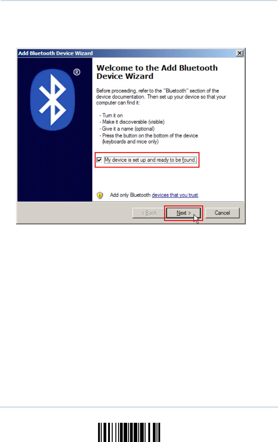
105
Update
Chapter 3
Set
up a WPAN Connection
4) Turn on the scanner with correct WPAN settings, such as select Bluetooth® SPP or Bluetooth®
HID, broadcasting enabled, authentication enabled, and PIN c ode specified, etc. Select the
check box of [My device is set up and ready to be found] on your computer.
5) Click [Next].
6) Wait for a few seconds for the Wizard to search available devices nearby.
The scanner will appear with its “serial number” as the device name. You may doubl e-check
the “Serial Number” label on the scanner to ens ure connecting with the correct scan ner.
Select the ta rget scanner. If the target scanner does not appear on the list, click [Search
Again] to refresh the list. The scanner might enter Suspend Mode now, and you can press the
trigger to have it active again (=discoverable). It will then stay active for a specified period of
time (2 minutes by default) and wait for PC to establish a connection.
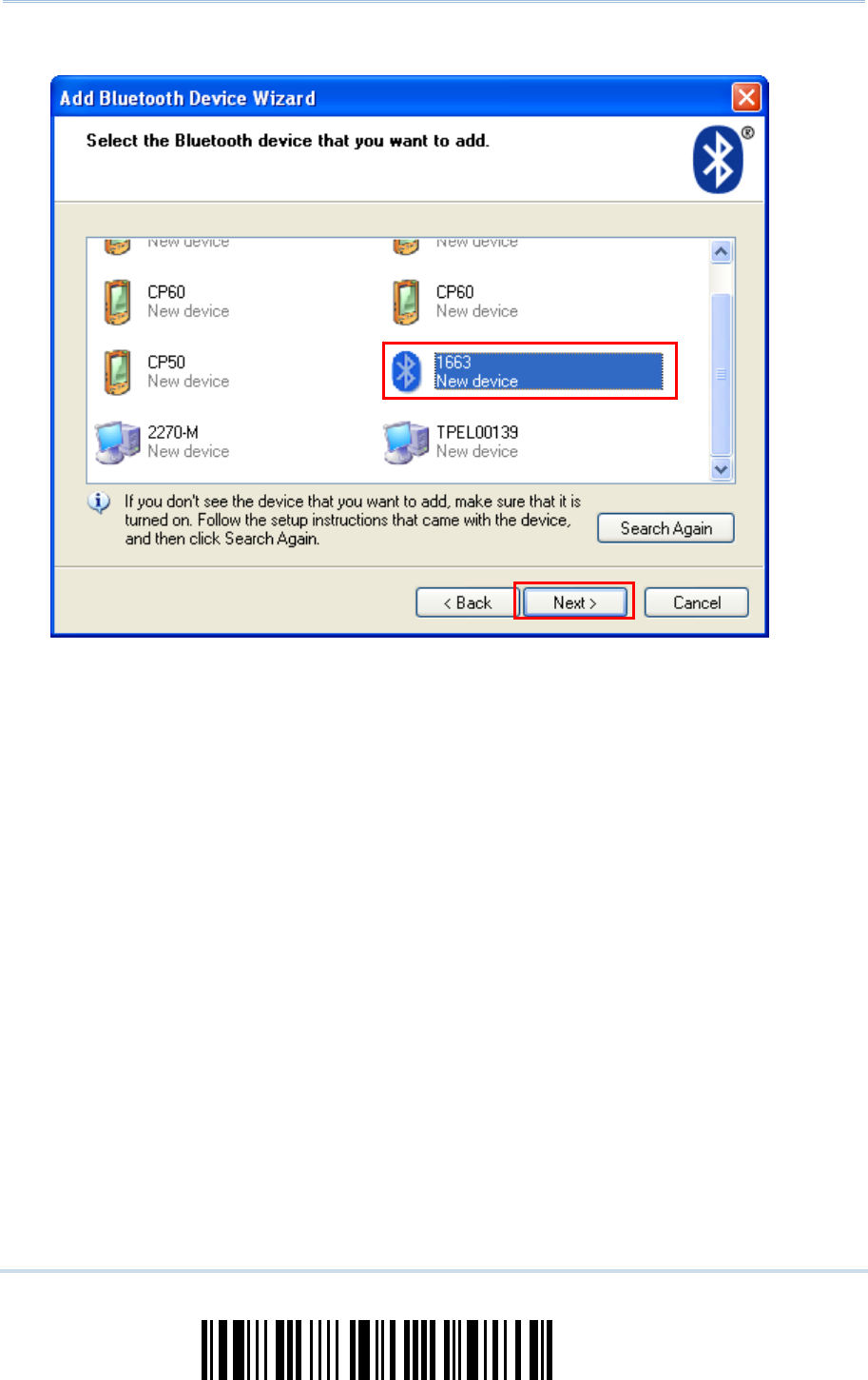
106
Enter Setup
1663 Barcode Scanner User Guide
7) Click [Next].
8) Enter the passkey for authentication, which must be exactly the same as configured for the
scanner.
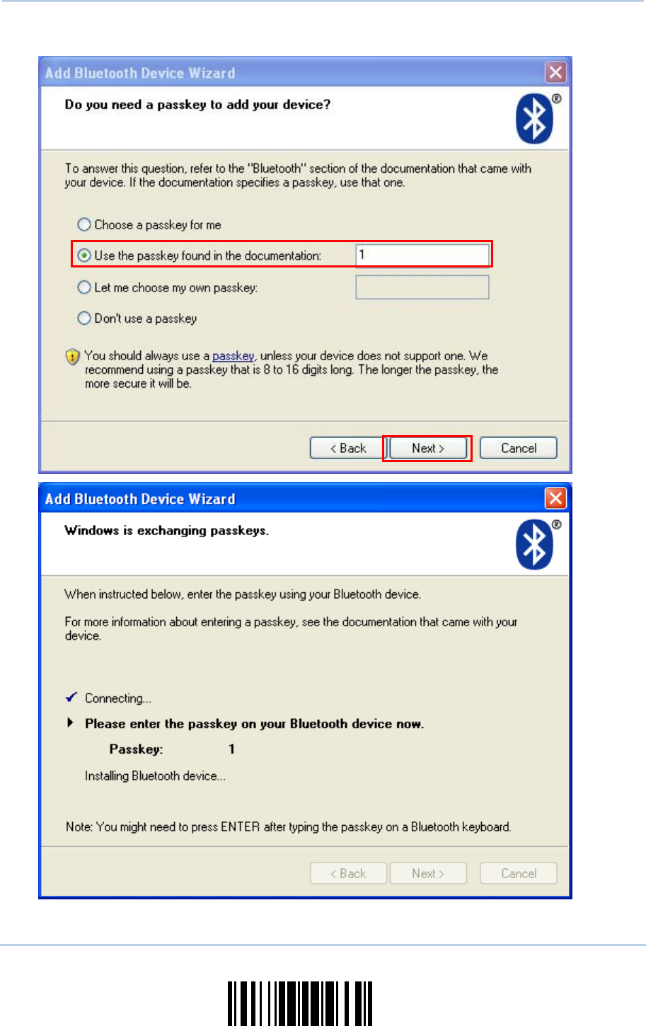
107
Update
Chapter 3
Set
up a WPAN Connection
9) Click [Next]. Wait for a few seconds for Windows to exchange passkeys.
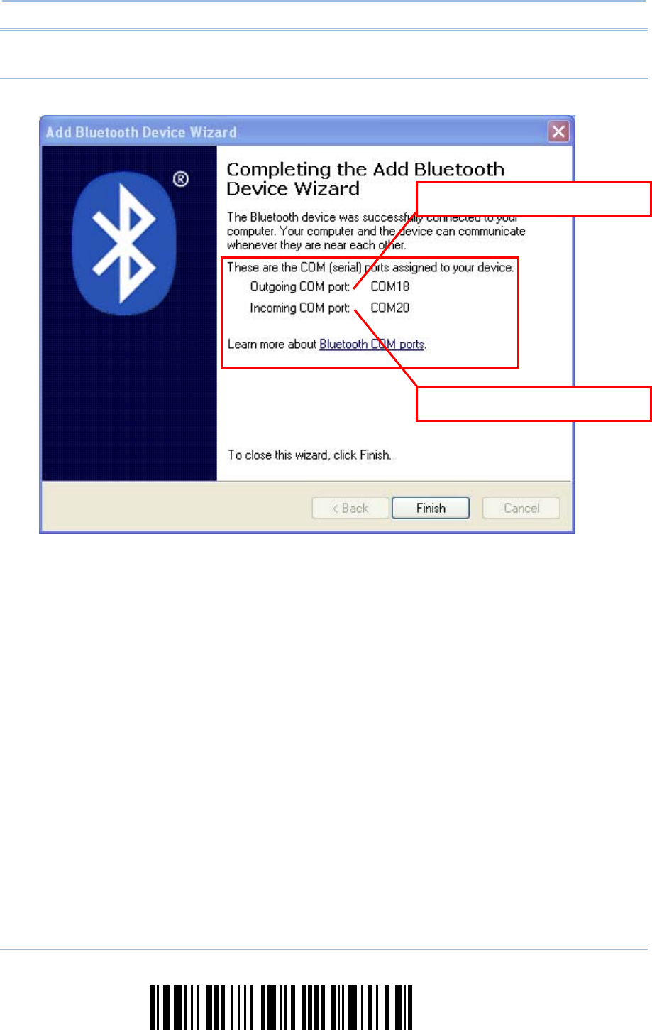
108
Enter Setup
1663 Barcode Scanner User Guide
Note: When Bluetooth security is enabled without pr oviding a pre-set PIN code, dynamic
input of PIN code is supported.
10) Click [Finish].
1
66
3
as
B
luetooth
®
SPP Slave
1
66
3
as
B
luetooth
®
SPP Master
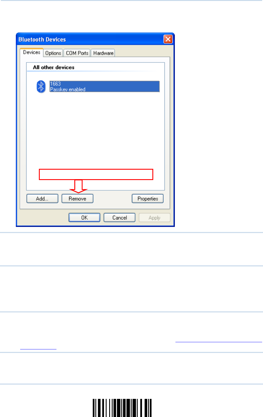
109
Update
Chapter 3
Set
up a WPAN Connection
11) Now the target scanner will be listed as below.
You can have up to seven scanners connected to one computer at the same time.
Note: When any changes are made to authentication and PIN code on the s canner side,
or you want to change to use Bluetooth® HID, it is suggested that you remove the
scanner from the paired device list (ca lled unpairing) and go through the whole
process to re-establish the connection.
12) Run the desired application on your computer, such as HyperTerminal.exe if using Bluetooth®
SPP or Notepad.exe if using Bluetooth® HID.
The status of the scanner li sted on the device list will be updated to “Connected”, indicating
the WPAN connection is established successfully via the outgoing COM port if u sing
Bluetooth® SPP.
Note: Even though the scanner is connected to the host with authentication disabled (=
no PIN code required), the host may still request a PIN code while the application
is opening COM port. Dynamic input of PIN code is supported so that you may
input a matching PIN code on the scanner. Refer to Disable Authentication or Use
Random PIN.
Click to remove the
s
e
lect
e
d ite
m
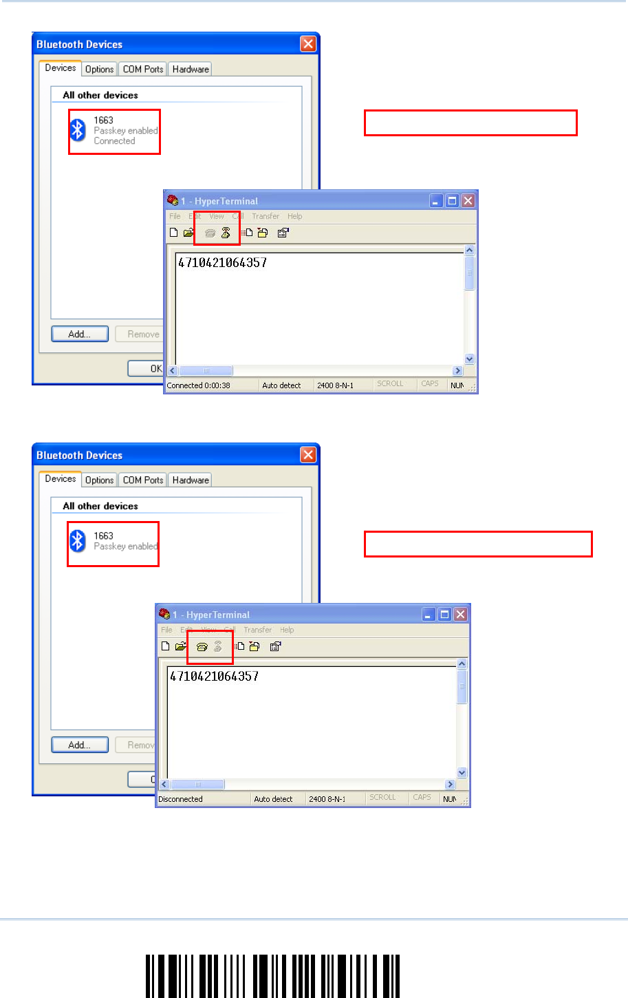
110
Enter Setup
1663 Barcode Scanner User Guide
B
luetooth
®
S
PP Connecte
d
B
luetooth
®
SPP Disconnecte
d

111
Update
In this chapter, a brief on the symbology settings is provided for your reference.
IN THIS CHAPTER
4.1 Codabar ..................................................................112
4.2 Code 25 – Industrial 25 .............................................114
4.3 Code 25 – Interleaved 25...........................................117
4.4 Code 25 – Matrix 25..................................................120
4.5 Code 39 ..................................................................123
4.6 Code 93 .................................................................125
4.7 Code 128.................................................................125
4.8 EAN-8 .....................................................................126
4.9 EAN-13 ...................................................................128
4.10 GS1-128 (EAN-128) ................................................131
4.11 ISBT 128 ..............................................................132
4.12 MSI.......................................................................133
4.13 French Pharmacode.................................................135
4.14 Italian Pharmacode .................................................136
4.15 Plessey..................................................................137
4.16 GS1 DataBar (RSS Family) .......................................138
4.17 Telepen .................................................................143
4.18 UPC-A ...................................................................144
4.19 UPC-E ...................................................................146
Chapter 4
CHANGE SYMBOLOGY SETTINGS
112
Enter Setup
1663 Barcode Scanner User Guide
4.1 CODABAR
*Enable
Disable
4.1.1 SECURITY LEVEL
The scanner allows yo u to adjust the CODABAR security level between high or normal
level.
* High
Normal
4.1.2 START/STOP CHARACTERS SELECTION
Select one of the four different start/stop character pairs –
* abcd/abcd
abcd/tn*e
ABCD/ABCD
ABCD/TN*E

113
Update
Chapter 4
Change Symbology Settings
4.1.3 START/STOP TRANSMISSION
Decide whether to include the start/stop characters in the data being transmitted.
Transmit Start/Stop
Characters
*Do Not Transmit
4.1.4 CLSI CONVERSION
When enabled, the CLSI editing strips the start/stop characters and inserts a space after
the first, fifth, and tenth characters of a 14-character Codabar barcode.
Apply CLSI Editing
*Do Not Apply
Note: The 14-character barcode length does not include start/stop characters.

114
Enter Setup
1663 Barcode Scanner User Guide
4.2 CODE 25 – INDUSTRIAL 25
*Enable
Disable
4.2.1 START/STOP PATTERN SELECTION
This decides t he readability of all 2 of 5 symbology variants. For example, flight tickets
actually use an Industrial 2 of 5 barcode but with Interleaved 2 of 5 start/stop pattern. In
order to read this barcode, the start/stop pattern selection parameter of Industrial 2 of 5
should set to "Interleaved 25".
*Industrial 25
Start/Stop Pattern
Interleaved 25
Start/Stop Pattern
Matrix 25
Start/Stop Pattern

115
Update
Chapter 4
Change Symbology Settings
4.2.2 VERIFY CHECK DIGIT
Decide whether to verify the check digit. If incorrect, the barcode will not be accepted.
Verify Industrial 25
Check Digit
*Do Not Verify
4.2.3 TRANSMIT CHECK DIGIT
Decide whether to include the check digit in the data being transmitted.
*Transmit
I
ndustrial 25
Check Digit
Do Not Transmit

116
Enter Setup
1663 Barcode Scanner User Guide
4.2.4 CODE LENGTH QUALIFICATION
To prevent the "short scan" e rror, define the "Length Qualification" settings to ensure
that the correct barcode is read by qualifying the allowable code length.
If "Max/Min Length" is selected, the maximum length and the minimum length must
be specified. It on ly accepts those barcodes with lengths that fall between max/min
lengths specified.
If “Fixed Length” is selected, up to 2 fixed lengths can be specified.
6) Read the barcode to enable either Max. /Min. Length qualification or Fixed Length(s)
qualification.
*Enable Max./Min.
Length (0~127)…
Enable Fixed
Length(s)…
7) Read the barcode for Max. Length or Fixed Length 1, and follow steps 3~4.
Repeat steps 2~4 for Min. Length or Fixed Length 2.
Max. Length (*127) or
Fixed Length 1
Min. Length (*4) or
Fixed Length 2
8) Read the “Decimal Value” barcode on page 219 for the desired length.
9) Read the “Validate” barcode on the same page to complete this setting.

117
Update
Chapter 4
Change Symbology Settings
4.3 CODE 25 – INTERLEAVED 25
*Enable
Disable
4.3.1 START/STOP PATTERN SELECTION
This decides t he readability of all 2 of 5 symbology variants. For example, flight tickets
actually use an Industrial 2 of 5 barcode but with Interleaved 2 of 5 start/stop pattern. In
order to read this barcode, the start/stop pattern selection parameter of Industrial 2 of 5
should set to "Interleaved 25".
Industrial 25
Start/Stop Pattern
*Interleaved 25
Start/Stop Pattern
Matrix 25
Start/Stop Pattern

118
Enter Setup
1663 Barcode Scanner User Guide
4.3.2 VERIFY CHECK DIGIT
Decide whether to verify the check digit. If incorrect, the barcode will not be accepted.
Verify
I
nterleaved 25
Check Digit
*Do Not Verify
4.3.3 TRANSMIT CHECK DIGIT
Decide whether to include the check digit in the data being transmitted.
*Transmit
I
nterleaved 25
Check Digit
Do Not Transmit

119
Update
Chapter 4
Change Symbology Settings
4.3.4 CODE LENGTH QUALIFICATION
To prevent the "short scan" e rror, define the "Length Qualification" settings to ensure
that the correct barcode is read by qualifying the allowable code length.
If "Max/Min Length" is selected, the maximum length and the minimum length must
be specified. It on ly accepts those barcodes with lengths that fall between max/min
lengths specified.
If “Fixed Length” is selected, up to 2 fixed lengths can be specified.
10) Read the barcode to enable either Max. /Min. Length qualification or Fixed Length(s)
qualification.
*Enable Max./Min.
Length (0~127)…
Enable Fixed
Length(s)…
11) Read the barcode for Max. Length or Fixed Length 1, and follow steps 3~4.
Repeat steps 2~4 for Min. Length or Fixed Length 2.
Max. Length (*126) or
Fixed Length 1
Min. Length (*4) or
Fixed Length 2
12) Read the “Decimal Value” barcode on page 219 for the desired length.
13) Read the “Validate” barcode on the same page to complete this setting.

120
Enter Setup
1663 Barcode Scanner User Guide
4.4 CODE 25 – MATRIX 25
Enable
*Disable
4.4.1 START/STOP PATTERN SELECTION
This decides t he readability of all 2 of 5 symbology variants. For example, flight tickets
actually use an Industrial 2 of 5 barcode but with Interleaved 2 of 5 start/stop pattern. In
order to read this barcode, the start/stop pattern selection parameter of Industrial 2 of 5
should set to "Interleaved 25".
Industrial 25
Start/Stop Pattern
Interleaved 25
Start/Stop Pattern
*
Matrix 25
Start/Stop Pattern

121
Update
Chapter 4
Change Symbology Settings
4.4.2 VERIFY CHECK DIGIT
Decide whether to verify the check digit. If incorrect, the barcode will not be accepted.
Verify Matrix 25
Check Digit
*Do Not Verify
4.4.3 TRANSMIT CHECK DIGIT
Decide whether to include the check digit in the data being transmitted.
*Transmit Matrix 25
Check Digit
Do Not Transmit

122
Enter Setup
1663 Barcode Scanner User Guide
4.4.4 CODE LENGTH QUALIFICATION
To prevent the "short scan" e rror, define the "Length Qualification" settings to ensure
that the correct barcode is read by qualifying the allowable code length.
If "Max/Min Length" is selected, the maximum length and the minimum length must
be specified. It on ly accepts those barcodes with lengths that fall between max/min
lengths specified.
If “Fixed Length” is selected, up to 2 fixed lengths can be specified.
14) Read the barcode to enable either Max. /Min. Length qualification or Fixed Length(s)
qualification.
*Enable Max./Min.
Length (0~127)…
Enable Fixed
Length(s)…
15) Read the barcode for Max. Length or Fixed Length 1, and follow steps 3~4.
Repeat steps 2~4 for Min. Length or Fixed Length 2.
Max. Length (*127) or
Fixed Length 1
Min. Length (*4) or
Fixed Length 2
16) Read the “Decimal Value” barcode on page 219 for the desired length.
17) Read the “Validate” barcode on the same page to complete this setting.

123
Update
Chapter 4
Change Symbology Settings
4.5 CODE 39
*Enable
Disable
4.5.1 START/STOP TRANSMISSION
Decide whether to include the start/stop characters in the data being transmitted.
Transmit Code 39
Start/Stop
Characters
*Do Not Transmit
4.5.2 VERIFY CHECK DIGIT
Decide whether to verify check digit. If incorrect, the barcode will not be accepted.
Verify Code 39
Check Digit
*Do Not Verify

124
Enter Setup
1663 Barcode Scanner User Guide
4.5.3 TRANSMIT CHECK DIGIT
Decide whether to include the check digit in the data being transmitted.
*Transmit Code 39
Check Digit
Do Not Transmit
4.5.4 STANDARD/FULL ASCII CODE 39
Decide whether to support Code 39 Full ASCII that includes all t he alphanumeric and
special characters.
Code 39 Full ASCII
*Standard Code 39
4.5.5 SECURITY LEVEL
Decide the security level of Code 39.
*High
Normal

125
Update
Chapter 4
Change Symbology Settings
4.6 CODE 93
*Enable
Disable
4.7 CODE 128
*Enable
Disable
4.7.1 SECURITY LEVEL
Decide the security level of Code 39.
*High
Normal
126
Enter Setup
1663 Barcode Scanner User Guide
4.8 EAN-8
EAN-8
*Enable EAN-
8
(No Addon)
Disable
EAN-8 Addon 2
Enable EAN-8 Addon 2
*Disable
EAN-8 Addon 5
Enable EAN-8 Addon 5
*Disable

127
Update
Chapter 4
Change Symbology Settings
4.8.1 CONVERT TO EAN-13
Decide whether to expand the read EAN-8 barcode, as well as its addons, into EAN-13.
After conversion, the data follows EAN-13 format a nd is affected by EAN-13
programming selections (e.g. Check Digit).
Convert EAN-8 to
EAN-13
*Do Not Convert
4.8.2 TRANSMIT CHECK DIGIT
Decide whether to include the check digit in the data being transmitted.
*Transmit EAN-8
Check Digit
Do Not Transmit
128
Enter Setup
1663 Barcode Scanner User Guide
4.9 EAN-13
EAN-13
*Enable EAN-
1
3
(No Addon)
Disable
EAN-13 Addon 2
Enable EAN-13 Addon 2
*Disable
EAN-13 Addon 5
Enable EAN-13 Addon 5
*Disable

129
Update
Chapter 4
Change Symbology Settings
4.9.1 ISBN CONVERSION
Decide whether to convert the EAN-13 barcode, starting with 978 and 979, to ISBN.
Convert EAN-13 to
ISBN
*Do Not Convert
4.9.2 ISSN CONVERSION
Decide whether to convert the EAN-13 barcode, starting with 977 to ISSN.
Convert EAN-13 to
ISSN
*Do Not Convert
4.9.3 TRANSMIT CHECK DIGIT
Decide whether to include the check digit in the data being transmitted.
*Transmit EAN-13
Check Digit
Do Not Transmit

130
Enter Setup
1663 Barcode Scanner User Guide
4.9.4 SECURITY LEVEL
Select the security level for reading EAN-13 barcodes.
Normal
*High
131
Update
Chapter 4
Change Symbology Settings
4.10 GS1-128 (EAN-128)
*Enable
Disable
Note: GS1-128 barcodes can be decoded only when this setting is enabled. However, for
1660 with firmware version no later than 1.30, GS1-128 barcodes are taken a s
Code 128 when this setting is disabled.
4.10.1 CODE ID TRANSMISSION
Decide whether to include the Code ID ("]C1") in the data being transmitted.
Transmit Code ID
*Do Not Transmit
4.10.2 FIELD SEPARATOR (GS CHARACTER)
Decide whether to apply a field separator (to convert the FNC1 control character to human
readable character).
Enable Field
Separator…
18) Read the barcode above to enable field separator.
19) Read the “Hexadecimal Value” barcode on page 220 for the desired character string.
20) Read the “Validate” barcode to complete this setting.
Note: GS1-128 barcodes start with the FNC1 control character to distinguish themselves
from other uses of Code 128. FNC1 is also used to separate data fields in the
GS1-128 barcodes.

132
Enter Setup
1663 Barcode Scanner User Guide
4.11 ISBT 128
*Enable
Disable
Note: When enabled, it not only can decode single ISBT barcode, but also decode and
concatenates pairs of ISBT barcodes.
133
Update
Chapter 4
Change Symbology Settings
4.12 MSI
Enable
*Disable
4.12.1 VERIFY CHECK DIGIT
Select one of the three calculations to veri fy check di git when decoding barcodes. If
incorrect, the barcode will not be accepted.
*Single Modulo 10
Double Modulo 10
Modulo 10 & 11
4.12.2 TRANSMIT CHECK DIGIT
Decide whether to include the check digit in the data being transmitted.
*Last Digit Not
Transmitted
Both Digits
Transmitted
B
oth Digits
Not Transmitted

134
Enter Setup
1663 Barcode Scanner User Guide
4.12.3 CODE LENGTH QUALIFICATION
To prevent the "short scan" e rror, define the "Length Qualification" settings to ensure
that the correct barcode is read by qualifying the allowable code length.
If "Max/Min Length" is selected, the maximum length and the minimum length must
be specified. It on ly accepts those barcodes with lengths that fall between max/min
lengths specified.
If “Fixed Length” is selected, up to 2 fixed lengths can be specified.
21) Read the barcode to enable either Max. /Min. Length qualification or Fixed Length(s)
qualification.
*Enable Max./Min.
Length (0~127)…
Enable Fixed
Length(s)…
22) Read the barcode for Max. Length or Fixed Length 1, and follow steps 3~4.
Repeat steps 2~4 for Min. Length or Fixed Length 2.
Max. Length (*127) or
Fixed Length 1
Min. Length (*4) or
Fixed Length 2
23) Read the “Decimal Value” barcode on page 219 for the desired length.
24) Read the “Validate” barcode on the same page to complete this setting.

135
Update
Chapter 4
Change Symbology Settings
4.13 FRENCH PHARMACODE
Enable
*Disable
4.13.1 TRANSMIT CHECK DIGIT
Decide whether to include the check digit in the data being transmitted.
*
Transmit
F
rench Pharmacode
Check Digit
Do Not Transmit

136
Enter Setup
1663 Barcode Scanner User Guide
4.14 ITALIAN PHARMACODE
Enable
*Disable
4.14.1 TRANSMIT CHECK DIGIT
Decide whether to include the check digit in the data being transmitted.
*
Transmit
I
talian Pharmacode
Check Digit
Do Not Transmit
137
Update
Chapter 4
Change Symbology Settings
4.15 PLESSEY
Enable
*Disable
4.15.1 CONVERT TO UK PLESSEY
Decide whether to change each o ccurrence of the chara cter 'A' to character 'X' in the
decoded data.
Convert to UK Plessey
*Do Not Convert
4.15.2 TRANSMIT CHECK DIGIT
Decide whether to include the two check digits in the data being transmitted.
*Transmit Plessey
Check Digits
Do Not Transmit

138
Enter Setup
1663 Barcode Scanner User Guide
4.16 GS1 DATABAR (RSS FAMILY)
It is categorized into three groups:
Group I — GS1 DataBar Omnidirectional (RSS-14)
This group consists of the following:
GS1 DataBar Omnidirectional
GS1 DataBar Truncated
GS1 DataBar Stacked
GS1 DataBar Stacked Omnidirectional
Group II — GS1 DataBar Expanded (RSS Expanded)
This group consists of the following:
GS1 DataBar Expanded
GS1 DataBar Expanded Stacked
Group III — GS1 DataBar Limited (RSS Limited)
This group consists of the following:
GS1 DataBar Limited
4.16.1 CODE ID SELECTION
Select a desired Code ID to use:
“]e0“ (GS1 DataBar Code ID)
“]C1” (GS1-128 Code ID)
Use “]C1”
*Use “]e0”
139
Update
Chapter 4
Change Symbology Settings
4.16.2 GS1 DATABAR OMNIDIRECTIONAL (RSS-14)
Enable RSS-
1
4 &
RSS Expanded
(Groups I, II)
*Disable
The settings below apply to Group I symbologies only:
GS1 DataBar Omnidirectional
GS1 DataBar Truncated
GS1 DataBar Stacked
GS1 DataBar Stacked Omnidirectional
Transmit Code ID
Decide whether to include the Code ID in the data being transmitted.
*Transmit RSS-14
Code ID
Do Not Transmit
Transmit Application ID
Decide whether to include the Application ID ("01") in the data being transmitted.
*Transmit RSS-14
Application ID
Do Not Transmit

140
Enter Setup
1663 Barcode Scanner User Guide
Transmit Check Digit
Decide whether to include the check digit in the data being transmitted.
*Transmit RSS-14
Check Digit
Do Not Transmit

141
Update
Chapter 4
Change Symbology Settings
4.16.3 GS1 DATABAR EXPANDED (RSS EXPANDED)
Enable RSS-
1
4 &
RSS Expanded
(Groups I, II)
*Disable
The settings below apply to Group II symbologies only:
GS1 DataBar Expanded
GS1 DataBar Expanded Stacked
Transmit Code ID
Decide whether to include the Code ID in the data being transmitted.
*
Transmit
RSS Expanded Code ID
Do Not Transmit
142
Enter Setup
1663 Barcode Scanner User Guide
4.16.4 GS1 DATABAR LIMITED (RSS LIMITED)
Enable RSS Limited
(Group III)
*Disable
Transmit Code ID
Decide whether to include the Code ID in the data being transmitted.
*
Transmit
RSS Limited Code ID
Do Not Transmit
Transmit Application ID
Decide whether to include the Application ID ("01") in the data being transmitted.
*
Transmit
RSS Limited
Application ID
Do Not Transmit
Transmit Check Digit
Decide whether to include the check digit in the data being transmitted.
*
Transmit
R
SS Limited
Check Digit
Do Not Transmit

143
Update
Chapter 4
Change Symbology Settings
4.17 TELEPEN
Enable Telepen
*Disable
4.17.1 TELEPEN OUTPUT – FULL ASCII/NUMERIC
Decide whether to support Telepen in full ASCII code. By default, it supports ASCII
mode.
AIM Telepen (Full ASCII) includes all the alphanumeric and special characters.
Original Telepen
(Numeric)
*AIM Telepen
144
Enter Setup
1663 Barcode Scanner User Guide
4.18 UPC-A
UPC-A
*Enable UPC-A
(No Addon)
Disable
UPC-A Addon 2
Enable UPC-A Addon 2
*Disable
UPC-A Addon 5
Enable UPC-A Addon 5
*Disable

145
Update
Chapter 4
Change Symbology Settings
4.18.1 CONVERT TO EAN-13
Decide whether to expand the read UPC-A barcode, as well as its addons, into EAN-13.
After conversion, the data follows EAN-13 format a nd is affected by EAN-13
programming selections (e.g. Check Digit).
Convert UPC-A to
EAN-13
*Do Not Convert
4.18.2 SYSTEM NUMBER TRANSMISSION
Decide whether to include the system number in the data being transmitted.
*Transmit UPC-A
System Number
Do Not Transmit
4.18.3 TRANSMIT CHECK DIGIT
Decide whether to include the check digit in the data being transmitted.
*Transmit UPC-A
Check Digit
Do Not Transmit
146
Enter Setup
1663 Barcode Scanner User Guide
4.19 UPC-E
UPC-E
*Enable UPC-
E
(No Addon)
Disable
UPC-E Addon 2
Enable UPC-E Addon 2
*Disable
UPC-E Addon 5
Enable UPC-E Addon 5
*Disable

147
Update
Chapter 4
Change Symbology Settings
4.19.1 SYSTEM NUMBER SELECTION
Decide whether to decode the ordinary UPC-E barcodes only or both UPC-E0 and UPC-E1
barcodes.
System number 0 enabled for decoding UPC-E0 barcodes.
System number 1 enabled for decoding UPC-E1 barcodes.
System Number 0 & 1
*System Number 0 Only
Warning: Because of the way system number 1 is encoded, if both system numbers
are enabled, the user might suffer from short scanning UPC-A or EAN-13
barcodes into UPC-E1 barcodes.
4.19.2 CONVERT TO UPC-A
Decide whether to expand the read UPC-E barcode, as well as its addons, into UPC-A.
After conversion, the data follows UPC-A format and is affected by UPC-A
programming selections (e.g. System Number, Check Digit).
Convert UPC-E to
UPC-A
*Do Not Convert

148
Enter Setup
1663 Barcode Scanner User Guide
4.19.3 SYSTEM NUMBER TRANSMISSION
Decide whether to include the system number in the data being transmitted.
Transmit UPC-E
System Number
*Do Not Transmit
4.19.4 TRANSMIT CHECK DIGIT
Decide whether to include the check digit in the data being transmitted.
*Transmit UPC-E
Check Digit
Do Not Transmit

149
Update
You may c onfigure the format of the col lected data outpu t to t he host co mputer.
Barcodes read by the scanner will be processed in the following sequence –
1) Perform character substitution on the data scanned.
2) Add Code ID and Length Code to the front of the data:[Code ID][Length Code][Data]
3) Process the whole data in step 2 with user formats. Data is now divided into fields by
user specified rules. Refer to Chapter 6 Applying Formats for Data Editing.
4) Add Prefix Code and Suffix Code before transmission: [Prefix Code][Processed
Data][Suffix Code]
IN THIS CHAPTER
5.1 Letter Case ..............................................................149
5.2 Character Substitution...............................................150
5.3 Prefix/Suffix Code .....................................................158
5.4 Code ID...................................................................159
5.5 Length Code ............................................................163
5.6 Multi-Barcode Editor..................................................167
5.7 Removal of Special Character .....................................170
5.1 LETTER CASE
By default, the alphabetics transmission is case-sensitive, meaning that the alphabet will
be transmitted according to their original case. Ignoring the original letter case, select
[Upper Case] to output data in upper case only; otherwise, select [Lower Case] to output
data in lower case only.
*Normal
Upper Case
Lower Case
Chapter 5
DEFINING OUTPUT FORMAT

150
Enter Setup
1663 Barcode Scanner User Guide
5.2 CHARACTER SUBSTITUTION
Character substitution is performed on every occurrence of the first character specified. If
only one character is specified, every occurrence of that character in the barcode will be
taken away.
The first character will be replaced by the second character(s).
Up to three sets of character substitution can be configured.
If “Bluetooth® HID” or “USB HID” is configured for interface, Key Type and Key Status
will then become appl icable. You may decide w hether or not to apply Key Status
when “Normal Key” is selected for Key Type.
Key Type Key Status
Scan Code Only 1 scan code value is allowed.
Refer to 5.2.1 Select a S et for
Character Substituion.
N/A
Normal Key Up to 3 character strings are allowed. Add Shift
Add Left Ctrl
Add Left Alt
Add Right Ctrl
Add Right Alt
Refer to Keyboard Wedge Table.
Note: The character substitution is performed only on the barcode itself and before the
processing of editing formats. It is n ot applicable to the Prefix/Suffix Code, Code
ID, Length Code, or any Additional Field.

151
Update
Chapter 5
Definin
g
Output Format
5.2.1 SELECT A SET FOR CHARACTER SUBSTITUION
Configure Set 1
Configure Set 2
Configure Set 3
1) Read the barcode above to enable character substitution by set.
For example, read the “Set 1” barcode to configure the fi rst set of c haracter
substitution. The scanner will respond with one short beep, high tone, to indicate
more setup barcodes are required.
2) Read the “Hexadecimal Value” barcode on page 220 for the de sired character
substitution. For example,
KEY TYPE = NORMAL
Read “3”, “0”, “2”, and “D” to replace the character “0” with a dash “-”.
Read “3”, “0”, “2”, “D”, “3”, and “0” to replace the character “0” with a dash “-0”.
KEY TYPE = SCAN CODE
If you want to replace the character “0” with “a” (= “1C” on the scan code table):
1. Read “3” and “0”.
2. Read the “Scan Code” barcode.
3. Read “1” and “C”.
KEY TYPE = NORMAL + KEY STATUS = SHIFT
If you want to replace the character “0” with “!” (= “Shift” + “1” on keyboard):
1. Read “3” and “0”.
2. Read the “Add Shift” barcode.
3. Read “3” and “1”.
3) Read the “Validate” barcode to complete this setting. (The defined set or sets will be
applied to all symbologies by default.)
152
Enter Setup
1663 Barcode Scanner User Guide
5.2.2 SYMBOLOGIES FOR CHARACTER SUBSTITUTION (ALL 3 SETS)
By default character substitution will be pe rformed on all sy mbologies. If the character
substitution is not des ired with one or mo re symbologies, read the “Do Not Apply”
barcode for each undesired symbologies and all the three sets will be ignored for them.
Character Substitution for Codabar
*Apply
Do Not Apply
Character Substitution for Code 39
*Apply
Do Not Apply
Character Substitution for Code 93
*Apply
Do Not Apply
Character Substitution for Code 128
*Apply
Do Not Apply

153
Update
Chapter 5
Definin
g
Output Format
Character Substitution for GS1-128
*Apply
Do Not Apply
Character Substitution for ISBT 128
*Apply
Do Not Apply
Character Substitution for EAN-8 (No Addon)
*Apply
Do Not Apply
Character Substitution for EAN-8 Addon 2
*Apply
Do Not Apply
Character Substitution for EAN-8 Addon 5
*Apply
Do Not Apply

154
Enter Setup
1663 Barcode Scanner User Guide
Character Substitution for EAN-13 (No Addon)
*Apply
Do Not Apply
Character Substitution for EAN-13 Addon 2
*Apply
Do Not Apply
Character Substitution for EAN-13 Addon 5
*Apply
Do Not Apply
Character Substitution for French Pharmacode
*Apply
Do Not Apply
Character Substitution for Italian Pharmacode
*Apply
Do Not Apply
155
Update
Chapter 5
Definin
g
Output Format
Character Substitution for Industrial 25
*Apply
Do Not Apply
Character Substitution for Interleaved 25
*Apply
Do Not Apply
Character Substitution for Matrix 25
*Apply
Do Not Apply
Character Substitution for MSI
*Apply
Do Not Apply
Character Substitution for Plessey
*Apply
Do Not Apply
156
Enter Setup
1663 Barcode Scanner User Guide
Character Substitution for GS1 DataBar
*Apply
Do Not Apply
Character Substitution for Telepen
*Apply
Do Not Apply
Character Substitution for UPC-A (No Addon)
*Apply
Do Not Apply
Character Substitution for UPC-A Addon 2
*Apply
Do Not Apply
Character Substitution for UPC-A Addon 5
*Apply
Do Not Apply

157
Update
Chapter 5
Definin
g
Output Format
Character Substitution for UPC-E (No Addon)
*Apply
Do Not Apply
Character Substitution for UPC-E Addon 2
*Apply
Do Not Apply
Character Substitution for UPC-E Addon 5
*Apply
Do Not Apply
158
Enter Setup
1663 Barcode Scanner User Guide
5.3 PREFIX/SUFFIX CODE
By default, there is no prefix code, and [ENTER] or [CR] (Carriage Return) is configured
to be suffix code. Up to 8 characters can be configured, for example, “Barcode_”, and
you will have the string appear in front of the barcode read, like this –
“Barcode_1234567890”.
If “Bluetooth® HID” or “USB HID” is configured for interface, Key Type and Key Status
will then become appl icable. You may decide w hether or not to apply Key Status
when “Normal Key” is selected for Key Type.
Key Type Key Status
Scan Code Up to 4 scan code values are allowed. N/A
Normal Key Up to 8 character strings are allowed. Add Shift
Add Left Ctrl
Add Left Alt
Add Right Ctrl
Add Right Alt
Refer to Keyboard Wedge Table.
Configure Prefix
Configure Suffix
1) Read the barcode above to apply prefix co de or suffix code separately, and follow
steps 2~3. (Max. 8 characters each)
2) Read the “Hexadecimal Value” barcode on pa ge 220 for the desired character string.
For example, read “2” and “B” for the scanner to prefix or suffix the character [+].
3) Read the “Validate” barcode to complete this setting.
159
Update
Chapter 5
Definin
g
Output Format
5.4 CODE ID
Up to two characters for Code ID can be configured for each symbology. To make the
Code ID configuration easier, the scanner provides five pre-defined Code ID sets that you
can select one and make necessary changes on it.
If “Bluetooth® HID” or “USB HID” is configured for interface, Key Type and Key Status
will then become appl icable. You may decide w hether or not to apply Key Status
when “Normal Key” is selected for Key Type.
Key Type Key Status
Scan Code Only 1 scan code value is allowed. N/A
Normal Key Up to 2 character strings are allowed. Add Shift
Add Left Ctrl
Add Left Alt
Add Right Ctrl
Add Right Alt
Refer to Keyboard Wedge Table.
Note: "]C1" is the Code ID of GS1-128 (EAN-128) barcodes; "]e0" is the default Code ID
of GS1 DataBar (RSS) barcodes.
5.4.1 SELECT PRE-DEFINED CODE ID
Apply Code ID Set 1
Apply Code ID Set 2
Apply Code ID Set 3
Apply Code ID Set 4
Apply Code ID Set 5

160
Enter Setup
1663 Barcode Scanner User Guide
Code ID options Set 1 Set 2 Set 3 Set 4 Set 5
Code 39 A C Y M A
Italian Pharmacode A C Y M A
French Pharmacode A C Y M A
Industrial 25 C H H H S
Interleaved 25 D I Z I S
Matrix 25 E G G G S
Codabar F N X N F
Code 93 I L L L G
Code 128 H K K K C
ISBT 128 H K K K C
UPC-E S E C E E
EAN-8 P B B FF E
EAN-13 M A A F E
UPC-A J A A A E
MSI V V D P M
Plessey W W E Q P
Telepen Z --- --- --- ---
161
Update
Chapter 5
Definin
g
Output Format
5.4.2 CHANGE CODE ID
1) Read the barcode below to change code ID of a specific symbology.
2) Read the “Hexadecimal Value” barcode on pa ge 220 for the desired character string.
For example, read “4” and “4” for applying the character [D] for Code ID.
3) Read the “Validate” barcode to complete this setting.
Configure Code ID for
Codabar
Configure Code ID for
Code 39
Configure Code ID for
Code 93
Configure Code ID for
Code 128
Configure Code ID for
ISBT 128
Configure Code ID for
EAN-8
Configure Code ID for
EAN-13
Configure Code ID for
French Pharmacode
Configure Code ID for
Italian Pharmacode
Configure Code ID for
Industrial 25

162
Enter Setup
1663 Barcode Scanner User Guide
Configure Code ID
for Interleaved 25
Configure Code ID
for Matrix 25
Configure Code ID
for MSI
Configure Code ID
for Plessey
Configure Code ID
for Telepen
Configure Code ID
for UPC-A
Configure Code
ID for UPC-E
5.4.3 CLEAR CODE ID SETTINGS
Clear All Code ID
Settings
163
Update
Chapter 5
Definin
g
Output Format
5.5 LENGTH CODE
A 4-digit code representing the length of ba rcode data (character count) can be inserted
in front of data being transmitted. Such "Le ngth" code can be individually enabled or
disabled for each symbology.
Length Code for Codabar
Apply
*Do Not Apply
Length Code for Code 39
Apply
*Do Not Apply
Length Code for Code 93
Apply
*Do Not Apply
Length Code for Code 128
Apply
*Do Not Apply

164
Enter Setup
1663 Barcode Scanner User Guide
Length Code for GS1-128 & GS1 DataBar
Apply
*Do Not Apply
Length Code for ISBT 128
Apply
*Do Not Apply
Length Code for EAN-8
Apply
*Do Not Apply
Length Code for EAN-13
Apply
*Do Not Apply
Length Code for French Pharmacode
Apply
*Do Not Apply

165
Update
Chapter 5
Definin
g
Output Format
Length Code for Italian Pharmacode
Apply
*Do Not Apply
Length Code for Industrial 25
Apply
*Do Not Apply
Length Code for Interleaved 25
Apply
*Do Not Apply
Length Code for Matrix 25
Apply
*Do Not Apply
Length Code for MSI
Apply
*Do Not Apply
166
Enter Setup
1663 Barcode Scanner User Guide
Length Code for Plessey
Apply
*Do Not Apply
Length Code for Telepen
Apply
*Do Not Apply
Length Code for UPC-A
Apply
*Do Not Apply
Length Code for UPC-E
Apply
*Do Not Apply
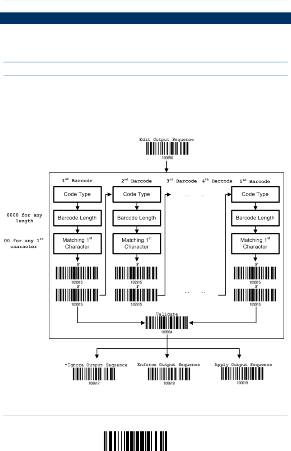
167
Update
Chapter 5
Definin
g
Output Format
5.6 MULTI-BARCODE EDITOR
The Multi-Barcode Editor allows deciding the output sequence of a concatenation of
barcodes. Up to five barcodes can be specified. When enable this mode, it will force the
scanner to apply Laser mode as the scan mode.
Note: The Multi-Barcode Editor has nothing to do with Multi-Barcode Mode.
The barcodes that are found m eeting the specified criteria below will be arranged in the
desired sequence.
Code Type
4-digit barcode length, excluding prefix, suffix, length code, etc.
Matching the first character of barcode data
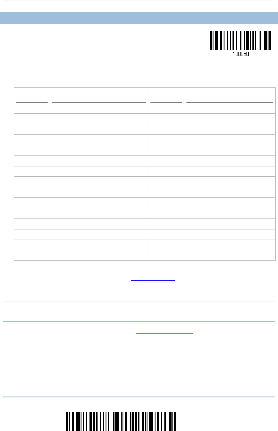
168
Enter Setup
1663 Barcode Scanner User Guide
5.6.1 EDIT A CONCATENATION OF BARCODES
Edit Output Sequence
1) Read the barcode above to start editing a concatenation of barcodes.
2) Code Type setting – r ead the “Hexadecimal Value” barcode on pa ge 220 for Code
Type of the (first) barcode. For example, read “4” and “1” for Code 39.
Code Type Symbology Code Type Symbology
40 (@) ISBT 128 4F (O) EAN-8 with Addon 5
41 (A) Code 39 50 (P) EAN-13
42 (B) Italian Pharmacode 51 (Q) EAN-13 with Addon 2
43 (C) French Pharmacode 52 (R) EAN-13 with Addon 5
44 (D) Industrial 25 53 (S) MSI
45 (E) Interleaved 25 54 (T) Plessey
46 (F) Matrix 25 55 (U) GS1-128 (EAN-128)
47 (G) Codabar (NW7) 56 (V) UPC-A
48 (H) Code 93 57 (W) UPC-A with Addon 2
49 (I) Code 128 58 (X) UPC-A with Addon 5
4A (J) UPC-E0 / UPC-E1
4B (K) UPC-E with Addon 2 5A (Z) Telepen
4C (L) UPC-E with Addon 5 5B ( [ ) GS1 DataBar (RSS)
4D (M) EAN-8
4E (N) EAN-8 with Addon 2
3) Barcode Length setting – read the “ Decimal Value” barcode on page 219 for the
4-digit length of the (fi rst) barcode. For example, read “0065” for barcode length of
65 characters or read “0000” for any length.
Note: If not reading 0000 for any length, the 4-digit length must exclude prefix, suffi x
(0x0d by default), length code, etc.
4) Matching Character setting – read the “ Hexadecimal Value” barcode on page 220 for
the 1st character that must be found matching in the (first) barcode. For exa mple,
read “4” and “1” for m atching character “A” as the fi rst character in the barcode or
read “00” for any character.
5) Read twice the “F” barcode on page 220 (“FF”) to co mplete the setting of each
barcode.
6) Read the “Validate” barcode to end the editing of the barcode set.
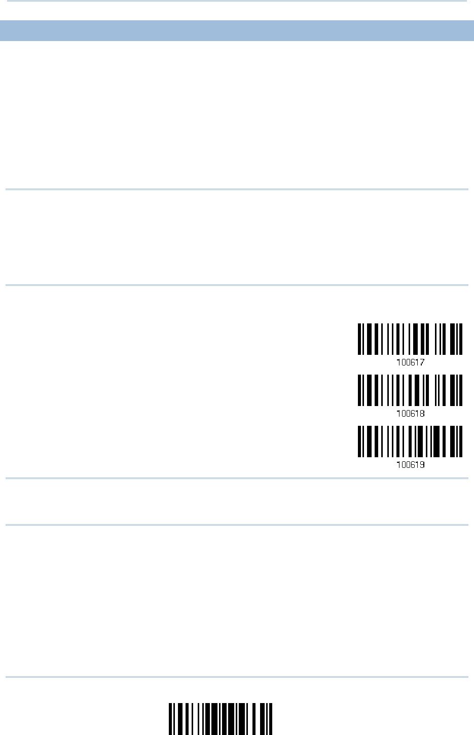
169
Update
Chapter 5
Definin
g
Output Format
5.6.2 ACTIVATE THE CONCATENATION OF BARCODES
By default, the output sequence editing of the concatenation of barcodes is not applied.
When “Enforce Output Sequence” is enabled, all barcodes read by the scanner must meet
with the criteria for the concatenation. If data is found excluded from all output sequence
sets (= not meeting with the criteria), the scanner will not accept the reading, and
therefore, data will not be transmitted.
When “Apply Output Sequence” is enabled, only barcodes found meeting with the criteria
are counted for the concatenation. Those found not meeting with the criteria ar e
processed normally and individually.
Note: When it requires reading more barcodes to complet e the “output sequence”
requirements, the scanner will respond with one short beep ( low tone). After
reading an acceptable barcode, its LED indicator will become solid green and go off
(= Good Read).
Upon completion of reading acceptable barcodes, the scanner will respond with
one short beep (high tone) and its LED indicator will become solid green and go off
(= Good Read).
*Ignore Output
Sequence
Enforce Output
Sequence
Apply Output
Sequence
Warning: When you disable the Multi-Barcode Editor later, the scan mode remain s
unchanged. If Laser mode is not desired, proceed to se lect a scan mode
that best suits your application.

170
Enter Setup
1663 Barcode Scanner User Guide
5.7 REMOVAL OF SPECIAL CHARACTER
You can only specify 1 ch aracter, but it will remove every matching character
encountered from the starting position of barcode data until a different character is met.
For example, if it is con figured to remove the character “0” (hex value is “30”), one or
more zeros will be stripped off the barcode data “012345” and “00012345”. However, for
barcode data “010333”, only the first zero will be stripped off.
Remove Special
Character
1) Read the barcode above to remove the specified character.
2) Read the “Hexadecimal Value” barcode on page 220 for the desired character string.
For example, read “3” and “0” for the scanner to remove the character “0”.
3) Read the “Validate” barcode to complete this setting.

171
Update
The scanner allows advanced data editing by applying user-configured editing formats.
The whole processed data can b e divided into fields by user -specified rules. The data
actually sent to the host computer comprises those fields together with the
user-configurable additional fields.
[Time
Stamp]
[Prefix
Code]
[Code
ID]
[Length
Code] [Data] Additional
Field(s)
[Time
Stamp]
[Suffix
Code]
None
by
default
None
by
default
None
by
default
None
by
default
Barcode
itself
None
by
default
None
by
default
0x0d
by
default
IN THIS CHAPTER
6.1 Activating Editing Formats..........................................172
6.2 How to Configure Editing Formats ...............................174
6.3 Configure Format — Define Data Criteria......................177
6.4 Configure Format — Define Data Field .........................186
6.5 Configure Format — Define Transmission Sequence .......195
6.6 Programming Examples .............................................197
Chapter 6
APPLYING FORMATS FOR DATA EDITING
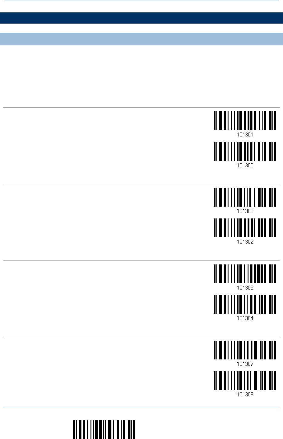
172
End Programming Format
1663 Barcode Scanner User Guide
6.1 ACTIVATING EDITING FORMATS
6.1.1 ACTIVATE EDITING FORMATS
If you have already configured any editing format before, you may directly apply the
editing format. If not, you must start with configuring an editing format first, and then,
activate the editing format when it is desired in use.
Editing Format 1
Enable
*Disable
Editing Format 2
Enable
*Disable
Editing Format 3
Enable
*Disable
Editing Format 4
Enable
*Disable

173
Update
Chapter 6
Applyin
g
Formats for Data Editin
g
Editing Format 5
Enable
*Disable
6.1.2 EXCLUSIVE DATA EDITING
By default, only barcodes found m eeting with the criteria are processed by t he editing
formats. Those found not meeting with the criteria are processed normally.
When “Exclusive Data Editing” is en abled, all barcodes read by the scanner must be
processed by the editing formats. If data is f ound excluded from all enabled editing
formats (= not meeting with the specif ied criteria), the scanner will not accept the
reading, and therefore, data will not be transmitted.
Yes
*No
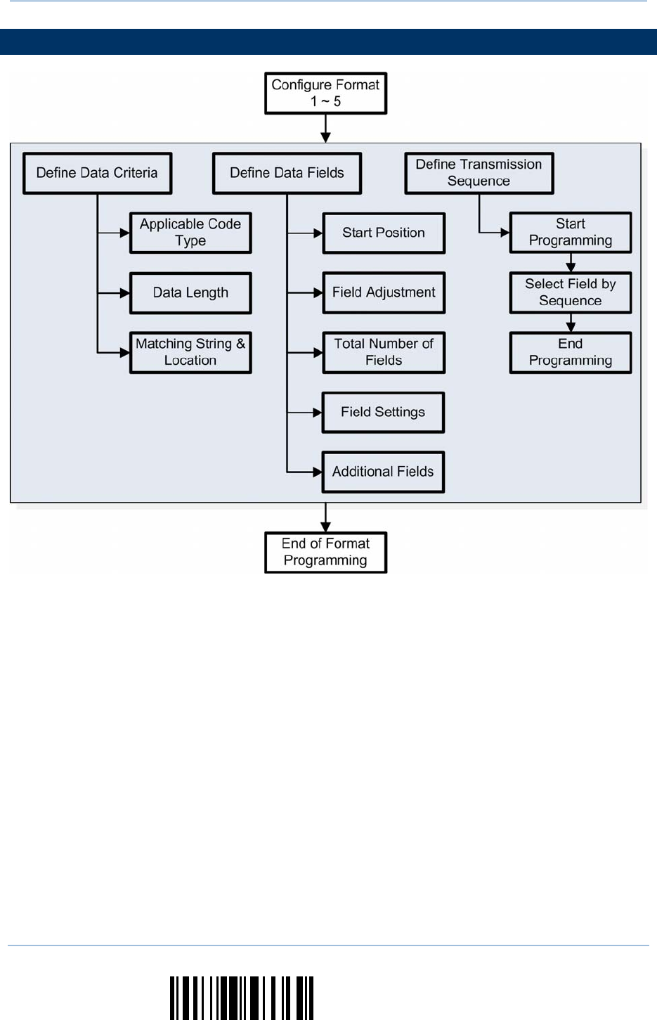
174
End Programming Format
1663 Barcode Scanner User Guide
6.2 HOW TO CONFIGURE EDITING FORMATS
175
Update
Chapter 6
Applyin
g
Formats for Data Editin
g
6.2.1 SELECT FORMAT TO CONFIGURE
Start Programming Format
Select one edi ting format (Format 1~5) and the p arameters pertaining to t he editing format can
then be configured – applicable code type, data length, matching string & location, start position,
field adjustment, total number of fields, field settings (field-dividing rule), additional fields, and
field transmission sequence.
Up to five different formats can be specified.
Configure Format 1
Configure Format 2
Configure Format 3
Configure Format 4
Configure Format 5
Note: Before completing the programming of an editing format, if any barcode for
parameters other than those pertaining to t he editing format is read, the
programming process will be automatically aborted.
End Programming Format
After having configured all the desired parameters, you must rea d the “End Programming Format”
barcode, which can be located at the bottom of every even page in this chapter.
End Programming
Format
176
End Programming Format
1663 Barcode Scanner User Guide
6.2.2 RESTORE DEFAULT FORMAT
You may select an existing editing format and have the def aults restored. The default
settings of an editing format are listed below.
Editing format Defaults
Applicable Code Type All
Data Length 0 (No qualification)
Matching String Disable
Matching String Location None
Start Position From head
Field Adjustment No adjustment
Total Number of Fields 1
Field Setting – field-dividing rule Not configured
Additional Fields None
Field Transmission Sequence F1
Restore Default
Format

177
Update
Chapter 6
Applyin
g
Formats for Data Editin
g
6.3 CONFIGURE FORMAT — DEFINE DATA CRITERIA
Three applicable conditions can b e configured to check whether the data read by t he
scanner can be processed by the particular editing format.
Note: Data editing cannot be performed unless the three conditions are all met.
6.3.1 APPLICABLE CODE TYPE
By default, barcodes of all the supported sy mbologies will be proces sed by any editing
format, if having been configured and enabl ed. For qui ck configuration, you may first
clear all, and then select the desired symbologies.
Note: You must have at least one symbology selected.
*Apply to All
Clear All

178
End Programming Format
1663 Barcode Scanner User Guide
Editing Format for Codabar
*Apply
Do Not Apply
Editing Format for Code 39
*Apply
Do Not Apply
Editing Format for Code 93
*Apply
Do Not Apply
Editing Format for Code 128
*Apply
Do Not Apply
Editing Format for GS1-128 & GS1 DataBar
*Apply
Do Not Apply
179
Update
Chapter 6
Applyin
g
Formats for Data Editin
g
Editing Format for ISBT 128
*Apply
Do Not Apply
Editing Format for EAN-8
*Apply
Do Not Apply
Editing Format for EAN-8 Addon 2
*Apply
Do Not Apply
Editing Format for EAN-8 Addon 5
*Apply
Do Not Apply
Editing Format for EAN-13
*Apply
Do Not Apply
180
End Programming Format
1663 Barcode Scanner User Guide
Editing Format for EAN-13 Addon 2
*Apply
Do Not Apply
Editing Format for EAN-13 Addon 5
*Apply
Do Not Apply
Editing Format for French Pharmacode
*Apply
Do Not Apply
Editing Format for Italian Pharmacode
*Apply
Do Not Apply
Editing Format for Industrial 25
*Apply
Do Not Apply
181
Update
Chapter 6
Applyin
g
Formats for Data Editin
g
Editing Format for Interleaved 25
*Apply
Do Not Apply
Editing Format for Matrix 25
*Apply
Do Not Apply
Editing Format for MSI
*Apply
Do Not Apply
Editing Format for Plessey
*Apply
Do Not Apply
Editing Format for Telepen
*Apply
Do Not Apply
182
End Programming Format
1663 Barcode Scanner User Guide
Editing Format for UPC-A
*Apply
Do Not Apply
Editing Format for UPC-A Addon 2
*Apply
Do Not Apply
Editing Format for UPC-A Addon 5
*Apply
Do Not Apply
Editing Format for UPC-E
*Apply
Do Not Apply
Editing Format for UPC-E Addon 2
*Apply
Do Not Apply

183
Update
Chapter 6
Applyin
g
Formats for Data Editin
g
Editing Format for UPC-E Addon 5
*Apply
Do Not Apply

184
End Programming Format
1663 Barcode Scanner User Guide
6.3.2 DATA LENGTH
The length must include prefix , suffix (0x0d by default), length code, etc. By default,
barcodes of any length (character count) are eligible for data editing.
A value ranging from 0 to 254 can be specified.
When zero is given to Max. & Mi n. Length, the scanner will not perform the length
qualification.
1) Read the barcode below to specify Max. Length or Min. Length separately, and follow
steps 2~3.
Max. Length
Min. Length
2) Read the “Decimal Value” barcode on page 219 for the desired length.
3) Read the “Validate” barcode on the same page to complete this setting.
185
Update
Chapter 6
Applyin
g
Formats for Data Editin
g
6.3.3 MATCHING STRING & LOCATION
By default, no matching string is specified, and therefore, it is disabled. You may enable
this feature by specifying a matching string up to four characters.
When the Matching String Location is z ero, the scanner w ill only check for the
existence of the matching string in the barcode data.
Specify a value from 1 to 254 to indicate where the matching string starts in the
barcode data.
1) Read the barcode to specify a matching string.
Matching String…
2) Read the “Hexadecimal Value” barcode on page 220 for the desired character string.
3) Read the “Validate” barcode to complete this setting.
4) Read the barcode to specify the location of the matching string.
Location of Matching
String…
5) Read the “Decimal Value” barcode on page 219 for the desired location.
6) Read the “Validate” barcode on the same page to complete this setting.
186
End Programming Format
1663 Barcode Scanner User Guide
6.4 CONFIGURE FORMAT — DEFINE DATA FIELD
6.4.1 START POSITION
Data can be divided into fields in one of the following direction –
from head (F1) to tail (F5)
from tail (F1) to head (F5)
*From Head
From Tail
6.4.2 FIELD ADJUSTMENT
You may apply equal length to all f ields, if necessary. If data is f ound longer than
specified, it will be t runcated automatically. When data is f ound shorter, it w ill add
“Space” (0x20) to field.
*No adjustment
Set length to adjust
fields… (*0)
1) Read the barcode above to adjust field by length.
2) Read the “Decimal Value” barcode on page 219 for the desired field length.
3) Read the “Validate” barcode on the same page to complete this setting.

187
Update
Chapter 6
Applyin
g
Formats for Data Editin
g
6.4.3 TOTAL NUMBER OF FIELDS
Data can b e divided into at most 6 fields; each of them is numbered from F1 to F6
accordingly. However, only F1~F5 can be configured.
The total number of fields mu st be specified correctly. If three fields are configured
for the editing format, the data ch aracters after F3 w ill be assigned to F 4
automatically. This feature is quite useful especially when data of variable lengths is
processed by editing formats.
*One Field
Two Fields
Three Fields
Four Fields
Five Fields
Six Fields
Note: The number of configurable fields is alw ays one less th an the total number of
fields specified. The extra data characters beyond the last field configured will be
automatically assigned to the next field.
188
End Programming Format
1663 Barcode Scanner User Guide
6.4.4 FIELD SETTINGS
Data eligible for editing formats is divided into fields by user-spe cified rules – either
using the field terminating string or specified field length.
By Terminating String
Specify the field terminating string. Up to two char acters are allowed. The scanner will search for
the occurrence of this particular string in the data.
By default, this string will be included in the field. You may discard it.
By Length
Alternatively, you may simpl y specify the fi eld length. The sca nner will assign the next speci fied
number of characters into the field.
Field 1 Setting
1) Read the barcode below to divide field 1 by a specified terminating string.
S
elect
F
ield Separator
to Divide Field 1…
2) Read the “Hexadecimal Value” barcode on page 220 for the desired character string.
3) Read the “Validate” barcode to complete this setting.
4) Read the “Discard Separator” barcode if the field separator is not desired in the field.
*Include Separator
Discard Separator
If not dividing the field by a specific separator, you may divide it by a specified length.
1) Read the barcode below to divide field 1 by length.
Div
i
de Field 1
by Length
2) Read the “Decimal Value” barcode on page 219 for the desired field length.
3) Read the “Validate” barcode on the same page to complete this setting.

189
Update
Chapter 6
Applyin
g
Formats for Data Editin
g
Field 2 Setting
1) Read the barcode below to divide field 2 by a specified terminating string.
S
elect
F
ield Separator
to Divide Field 2…
2) Read the “Hexadecimal Value” barcode on page 220 for the desired character string.
3) Read the “Validate” barcode to complete this setting.
4) Read the “Discard Separator” barcode if the field separator is not desired in the field.
*Include Separator
Discard Separator
If not dividing the field by a specific separator, you may divide it by a specified length.
1) Read the barcode below to divide field 2 by length.
D
ivide Field 2
by Length
2) Read the “Decimal Value” barcode on page 219 for the desired field length.
3) Read the “Validate” barcode on the same page to complete this setting.
190
End Programming Format
1663 Barcode Scanner User Guide
Field 3 Setting
1) Read the barcode below to divide field 3 by a specified terminating string.
S
e
lect
F
ield Separator
to Divide Field 3…
2) Read the “Hexadecimal Value” barcode on page 220 for the desired character string.
3) Read the “Validate” barcode to complete this setting.
4) Read the “Discard Separator” barcode if the field separator is not desired in the field.
*Include Separator
Discard Separator
If not dividing the field by a specific separator, you may divide it by a specified length.
1) Read the barcode below to divide field 3 by length.
D
ivide Field 3
by Length
2) Read the “Decimal Value” barcode on page 219 for the desired field length.
3) Read the “Validate” barcode on the same page to complete this setting.

191
Update
Chapter 6
Applyin
g
Formats for Data Editin
g
Field 4 Setting
1) Read the barcode below to divide field 4 by a specified terminating string.
S
elect
F
ield Separator
to Divide Field 4…
2) Read the “Hexadecimal Value” barcode on page 220 for the desired character string.
3) Read the “Validate” barcode to complete this setting.
4) Read the “Discard Separator” barcode if the field separator is not desired in the field.
*Include Separator
Discard Separator
If not dividing the field by a specific separator, you may divide it by a specified length.
1) Read the barcode below to divide field 4 by length.
D
ivide Field 4
by Length
2) Read the “Decimal Value” barcode on page 219 for the desired field length.
3) Read the “Validate” barcode on the same page to complete this setting.

192
End Programming Format
1663 Barcode Scanner User Guide
Field 5 Setting
1) Read the barcode below to divide field 5 by a specified terminating string.
S
elect
F
ield Separator
to Divide Field 5…
2) Read the “Hexadecimal Value” barcode on page 220 for the desired character string.
3) Read the “Validate” barcode to complete this setting.
4) Read the “Discard Separator” barcode if the field separator is not desired in the field.
*Include Separator
Discard Separator
If not dividing the field by a specific separator, you may divide it by a specified length.
1) Read the barcode below to divide field 5 by length.
D
ivide Field 5
by Length
2) Read the “Decimal Value” barcode on page 219 for the desired field length.
3) Read the “Validate” barcode on the same page to complete this setting.
193
Update
Chapter 6
Applyin
g
Formats for Data Editin
g
Additional Fields
Up to five additional fields can be created for each editing format; each of th em is numbered from
AF1 to AF5 accordingly.
If “Bluetooth® HID” or “USB HID” is configured for interface, Key Type and Key Status will then
become applicable. You may decide whether or not to appl y Key Status when “Normal Key” is
selected for Key Type.
Key Type Key Status
Scan Code Up to 2 scan code values are allowed.
N/A
Normal Key Up to 4 character strings are allowed. Add Shift
Add Left Ctrl
Add Left Alt
Add Right Ctrl
Add Right Alt
Refer to Keyboard Wedge Table.
1) Read the barcode below to specify an additional field, one at a time.
Additional Field 1…
Additional Field 2…
Additional Field 3…
Additional Field 4…
Additional Field 5…
2) Read the “Hexadecimal Value” barcode on page 220 for the desired additional field.
3) Read the “Validate” barcode to complete this setting.

194
End Programming Format
1663 Barcode Scanner User Guide
6.4.5 PAUSE FIELD SETTING
Pause Field Time
You can limit the pause time interval (1~16). By default, it is set to 1 second.
P
ause Field Time
1
~16 sec.
(*1)
1) Read the barcode above to speci fy the ti me interval for the Pause Field. (It i s set to 1 by
default.)
2) Read the “Decimal Value” barcode on page 219. For example, read “1” and “ 0” for setting the
Pause Field Time to 10 seconds.
3) Read the “Validate” barcode on the same page to complete this setting.

195
Update
Chapter 6
Applyin
g
Formats for Data Editin
g
6.5 CONFIGURE FORMAT — DEFINE TRANSMISSION SEQUENCE
After configuring the data fields and additional fields, you must now program the
transmission sequence of these fields that comprise the final data. This field transmission
sequence can be assigned in any desired order and fields can be assigned multiple times
as well.
Note: Up to twelve fields can be assigned.
1) Read the “Start” barcode to begin with programming the field transmission sequence.
Start Programming…
2) Program the transmission sequence by reading the desired fields as well as additional
fields.
Field 1
Field 2
Field 3
Field 4
Field 5
Field 6
Additional Field 1

196
End Programming Format
1663 Barcode Scanner User Guide
Additional Field 2
Additional Field 3
Additional Field 4
Additional Field 5
Pause Field
Null Character Field
3) Read the “End” barcode to complete this setting.
End Programming…

197
Update
Chapter 6
Applyin
g
Formats for Data Editin
g
6.6 PROGRAMMING EXAMPLES
6.6.1 EXAMPLE I
Extract data from the 10th character to the 19th character...
The editing format should be configured as follows:
1) Read the “Enter Setup” barcode to enter the Configuration Mode.
2) Read the “Configure Format 1” barcode.
3) Read the “Clear All” and “Code 128” barcodes for applicable code type.
4) Read the “Three Fields” barcode.
5) Read the “Divide Field 1 by Length” barcode, and set length to 9.
Field 1 data starts from the 1st character to the 9th character.
6) Read the “Divide Field 2 by Length” barcode, and set length to 10.
Field 2 data starts from the 10th character to the 19th character.
7) Read the “Start (Programming)” barcode to program the transmission sequence.
8) Read the “Field 2” barcode.
9) Read the “End” barcode to complete the transmission sequence setting.
10) Read the “End Programming Format” barcode to complete the setting of Editing Format 1.
11) Read the “Enable Format 1” barcode to apply Editing Format 1 to Code 128.
12) Read the “Update” barcode to exit the Configuration Mode.

198
End Programming Format
1663 Barcode Scanner User Guide
6.6.2 EXAMPLE II
Extract the date code, item number, and quantity information from barcodes.
Data in a barcode is encoded like this:
From the 1st character to the 6th character is the date code.
From the 7th character to the dash ‘-’ character is the item number.
After the dash ‘-’ character is the quantity information.
Data will be transmitted like this:
The item number goes first, then a TAB character, followed by the date code, then another TAB
character, and finally the quantity information.
The editing format should be configured as follows:
1) Read the “Enter Setup” barcode to enter the Configuration Mode.
2) Read the “Configure Format 2” barcode.
3) Read the “Three Fields” barcode.
4) Read the “Divide Field 1 by Length” barcode, and set length to 6.
Field 1 data starts from the 1st character to the 6th character.
5) Read the “Select Field Separator to Divide Field 2” barcode, and use a dash ‘-’ character.
Field 2 data starts from the 7th character until the dash ‘-’ character is met.
6) Read the “Additional Field 1” barcode, and use a tab character for the field.
7) Read the “Start (Programming)” barcode to program the transmission sequence.
8) Read the “Field 2”, “Additional Field 1”, “Field 1”, “Additional Field 1”, “Field 3” barcodes.
9) Read the “End” barcode to complete the transmission sequence (F2 A1 F1 A1 F3) setting.
10) Read the “End Programming Format” barcode to complete the setting of Editing Format 1.
11) Read the “Enable Format 2” barcode to apply Editing Format 2 to all code types.
12) Read the “Update” barcode to exit the Configuration Mode.
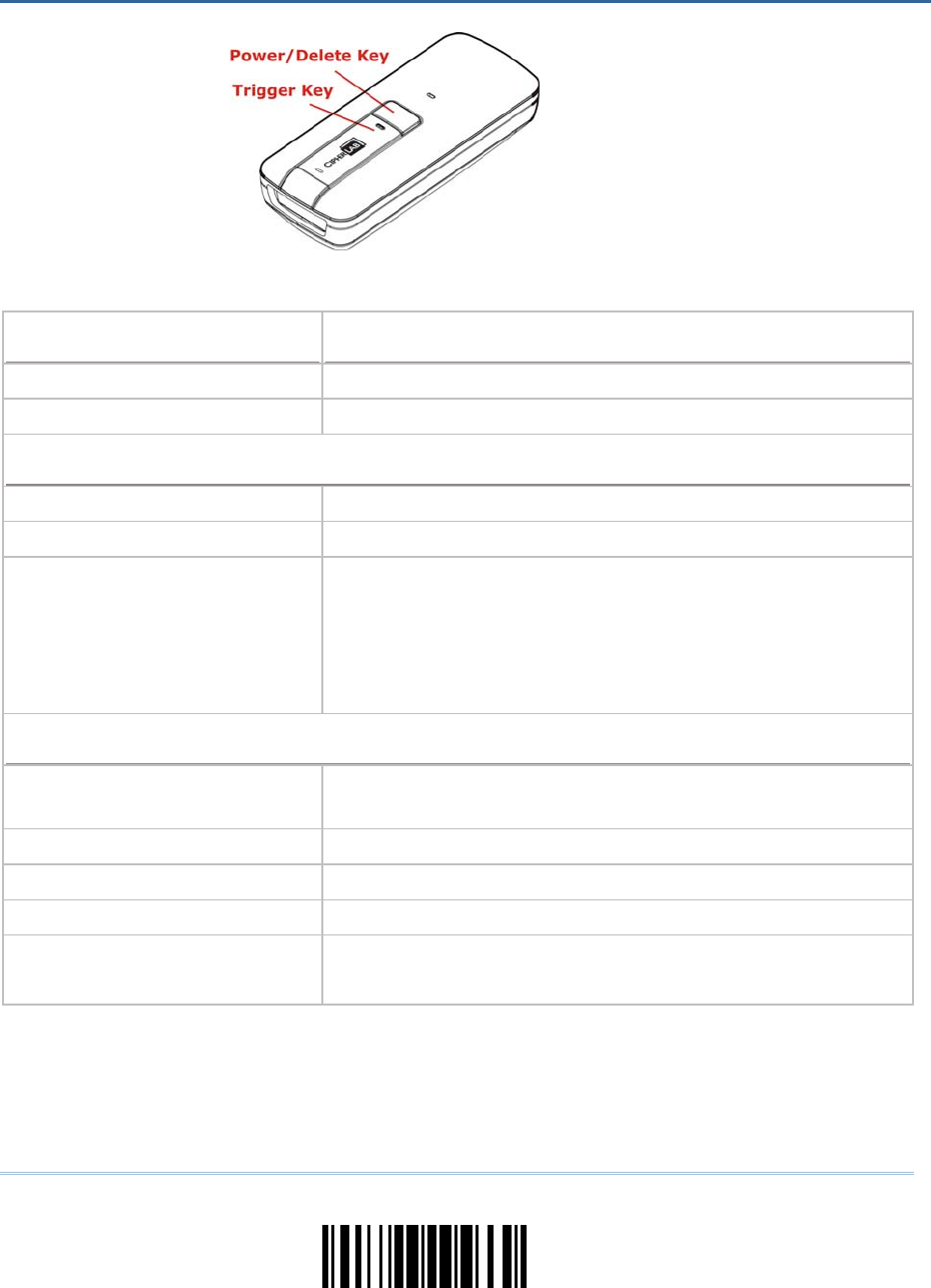
199
Update
Optical Characteristics 1663
Optical Sensor 2500 pixels CCD image sensor
Light Source Visible Red LED
RF Characteristics
WPAN Module Bluetooth® Class 3, Version 2.1
Coverage (line-of-sight) 20 meters with 3610
Interface Supported Serial Port Profile (Bluetooth® SPP)
Human Interface Device Profile (Bluetooth® HID)
3610
Direct USB HID
Direct USB Virtual COM
Physical Characteristics
Memory 10 KB for transmit buffer
4MB flash for memory mode
Switch Push-button switch for [Trigger] key, plus [Power/Delete] key
Indication Triple-color LED (Red/Green/Blue) and beeper
Dimensions 113 x 44.9 x 29.9 mm
Weight 106g (With Battery)
83g (Without Battery)
SPECIFICATIONS

200
Enter Setup
1663 Barcode Scanner User Guide
Electrical Characteristics
Battery Rechargeable Li-ion battery — 3.7 V, 850 mAh
Power Adaptor
Input AC 100~240 V (50/60 Hz)
Output DC 5V 2A (Battery Charger)
Operating Temperature 0 °C to 40 °C
Environmental Characteristics
Temperature Operating
Storage
0 °C to 50 °C
-20 °C to 60 °C
Humidity
(Non-condensing)
Operating
Storage
10% to 90%
5% to 95%
Resistance
Electrostatic Discharge ± 15 kV air discharge, ± 8 kV contact discharge
Programming Support
Configuration Use setup barcodes or host serial commands.
Software Windows®-based ScanMaster
Firmware upgradeable Download firmware updates via the download utility.
Accessories (√ means “supported”)
CipherLab Dongle (3610) √
Rechargeable Li-ion Battery √
Direct USB Cable √
Wristband √
Protective Cover (Pouch) √
Single Battery Charger √
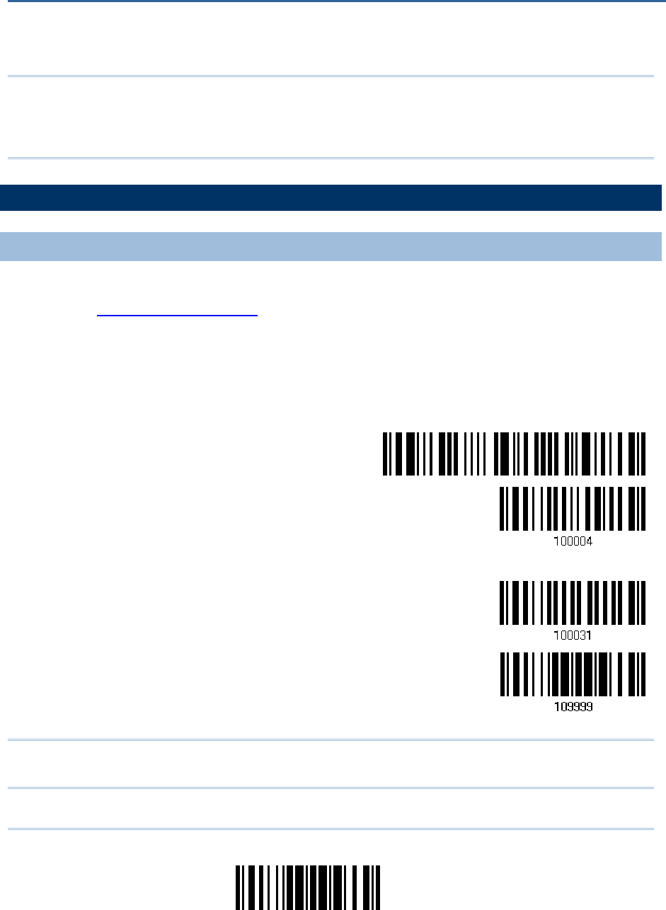
201
Update
Upgrade firmware to one scanner at a time. For example, turn off each of the rest
scanners when there is more than one scanner connected to host computer.
Note: 1. Ensure the scanner has a fully charged battery prior to attempting a firmware
upgrade.
2. In order to avoid the data loss during firmware upgrade. Please save or upload
all the data from the flash memory before beginning firmware upgrade.
HOW TO UPGRADE FIRMWARE
USING 3610
1) Connect 3610 to the USB port of PC after installing its driver.
2) Refer to 3.1.1 Connect to 3610 for connecting to 3610.
Read the “Set Connection” label first, and then the “Serial Number” label. Both labels
can be located at the back of 3610.
3) Read the following barcodes in sequence to configure the scanner to use USB Virtual
COM as do wnload interface. Only either ‘10 0004’ or ‘100031’ barcode should be
scanned for specifying the USB Virtual COM driver.
Enter Setup
Activate 3610 USB
Virtual COM
Or
Activate 3610 USB
Virtual COM_CDC
Update
Note: To activate the CDC driver, 3610’s firmware version must be 2.0 or later. You may
also choose to use “Direct” USB Virtual COM interface.
Appendix I
FIRMWARE UPGRADE
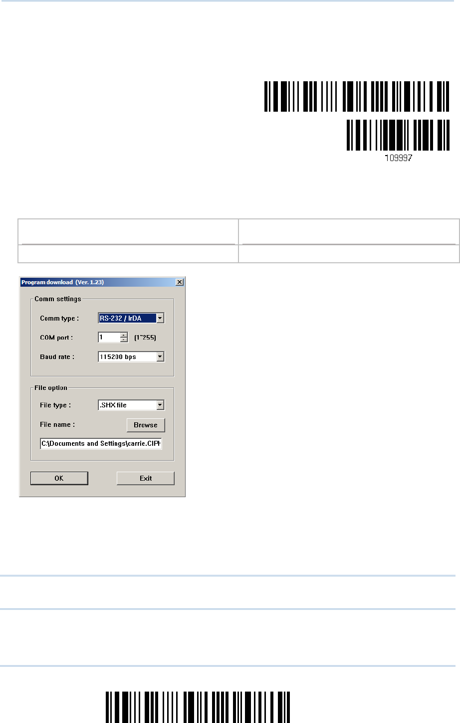
202
Enter Setup
1663 Barcode Scanner User Guide
4) Read the following barcodes in sequence for the scanner to enter the download mode.
The scanner will respond with beeps to indicate it is ready for downloading.
Enter Setup
Download
5) Run the download utility “ProgLoad.exe” on your computer.
Kernel Program User Program
K1663_V*.shx STD1663_V*.shx
For the co mmunication settings, select
“RS-232” and the correct COM port for US B
Virtual COM interface.
Ignore the baud rate setting.
For the fil e option, click [Browse] to sel ect
the target file for firmware update.
Click [OK].
6) After upgrading kernel, you will need to manually restart the scanner.
After upgrading the user program, the scanner will automatically restart itself once
the download is completed successfully.
Note: The output interface remains unchanged as specified in step 3 (= USB Virt ual
COM).
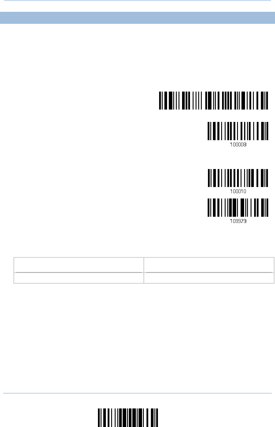
203
Update
Appendix I Firmware Upgrade
USE DIRECT USB VIRTUAL COM
1) Use the provided USB cable t o connect 1663 to the USB port of PC. You will need to
install its driver first!
2) Read the following barcodes in sequence to configure 1663 to use Direct USB Virtual
COM as dow nload interface and enter the download mode. The scanner will respond
with beeps to indicate it is ready for downloading. Only either ‘100008’ or ‘10 0010’
barcode should be scanned for specifying the USB Virtual COM driver.
Enter Setup
Activate Direct USB
Virtual COM
Or
Activate Direct USB
Virtual COM_CDC
Download
3) Run the download utility “ProgLoad.exe” on host computer.
Kernel Program User Program
K1663_V*.shx STD1663_V*.shx
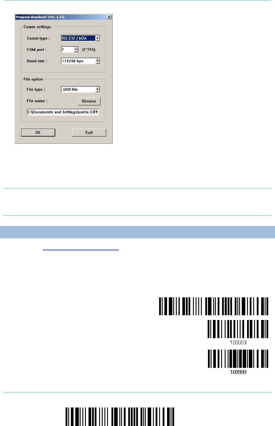
204
Enter Setup
1663 Barcode Scanner User Guide
For the co mmunication settings, select
“RS-232” and the corr ect COM por t for
Direct USB Virtual COM interface.
Ignore the baud rate setting.
For the fil e option, click [Browse] to sel ect
the target file for firmware update.
Click [OK].
4) After upgrading kernel, you will need to restart the scanner manually.
After upgrading the user program, the scanner will restart itself automatically once
the download is completely.
Note: Because 1663 supports the downloading of firmware via Direct USB Virtual COM
interface, the output interface will be set to the previously used one upon
completion of firmware upgrade.
USE BLUETOOTH® DONGLE
1) Refer to 3.2.3 Connect to Do ngle for the target scanner to accept the connection
request from your computer.
2) Read the following barcodes in sequence to configure the scanner to use Bluetooth®
SPP as download interface.
Enter Setup
Activate Bluetooth®
SPP
Update
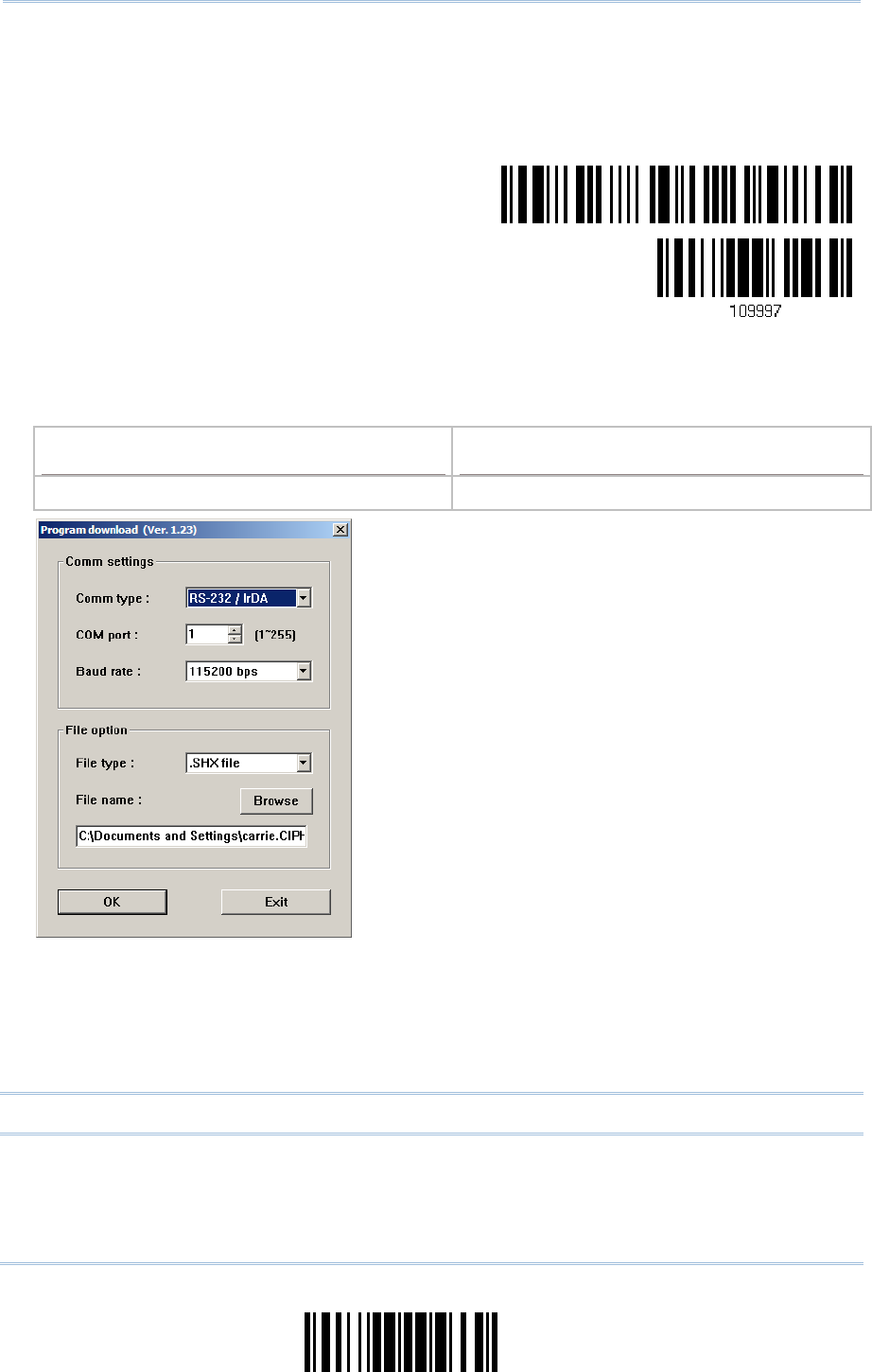
205
Update
Appendix I Firmware Upgrade
3) Read the following barcodes in sequence for the scanner to enter the download mode.
The scanner will respond with beeps to indicate it is ready for downloading.
Enter Setup
Download
4) Run the download utility “ProgLoad.exe” on your computer.
Kernel Program User Program
K1663_V*.shx STD1663_V*.shx
For the co mmunication settings, select
“RS-232” and the corr ect COM por t for
Bluetooth® SPP interface.
Ignore the baud rate setting.
For the fil e option, click [Browse] to sel ect
the target file for firmware update.
Click [OK].
5) After upgrading kernel, you will need to manually restart the scanner.
After upgrading the user program, the scanner will automatically restart itself once
the download is completed successfully.
Note: The output interface remains unchanged as specified in step 2 (=Bluetooth® SPP).
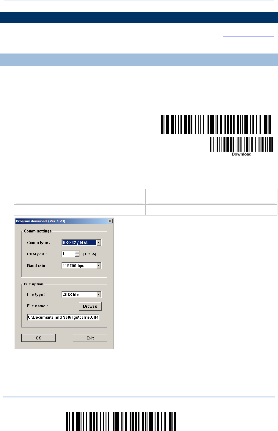
206
Enter Setup
1663 Barcode Scanner User Guide
HOW TO UPGRADE 3610 FIRMWARE
Connect 3610 to the USB port of PC after installing its driver. Refer to 3.1.1 Connect to
3610 for the target scanner to connect to 3610.
UPGRADE 3610 CPU FIRMWARE
1) Read the following barcodes in sequence for 3610 to enter the download mode. The
Communication LED on 3610 w ill be f lashing red to indicate it is rea dy for
downloading.
Enter Setup
Download 3610
CPU Firmware
2) Run the download utility “ProgLoad.exe” on your computer.
Kernel Program User Program
K3610_V*.shx STD3610_V*.shx
For the co mmunication settings, select
“RS-232” and the correct COM port for US B
Virtual COM interface.
Ignore the baud rate setting.
For the fil e option, click [Browse] to sel ect
the target file for firmware update.
Click [OK].
3) The 3610 will automatically restart itself when upgrading firmware is completed
successfully.
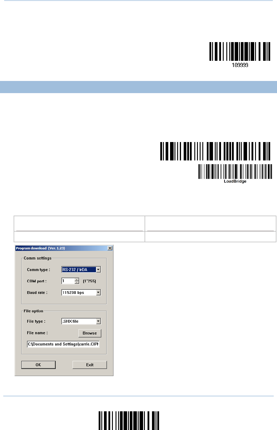
207
Update
Appendix I Firmware Upgrade
4) Read the “Update” b arcode for the scan ner to resume i ts operation (exit the
configuration mode).
Update
UPGRADE 3610 USB BRIDGE FIRMWARE
1) Read the following barcodes in sequence for 3610 to enter the download mode. The
Communication LED on 3610 w ill be f lashing red to indicate it is rea dy for
downloading.
Enter Setup
Download 3610
USB Bridge Firmware
2) Run the download utility “ProgLoad.exe” on your computer.
Kernel Program User Program
K3610Bridge_V*.shx STD3610Bridge_V*.shx
For the co mmunication settings, select
“RS-232” and the correct COM port for US B
Virtual COM interface.
Ignore the baud rate setting.
For the fil e option, click [Browse] to sel ect
the target file for firmware update.
Click [OK].

208
Enter Setup
1663 Barcode Scanner User Guide
3) The 3610 will automatically restart itself when upgrading firmware is completed
successfully.
4) Read the “Update” b arcode for the scan ner to resume i ts operation (exit the
configuration mode).
Update
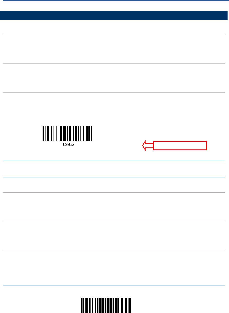
209
Update
SERIAL COMMANDS
D
Purpose To disable the scanner.
Remarks “D”
E
Purpose To enable the scanner.
Remarks “E”
#@ nnnnnn <CR>
Purpose To configure the scanner.
Remarks nnnnnn – the six digits of command parameters.
For example, “109952” is to list the current Code ID settings.
“0x23” + “0x40” + “0x31” + “0x30” + “0x39” + “0x39” + “0x35” + “0x32” + “0x0d”
Note: After configuring the scanner, you may send the serial command “#@109999” to
save the settings.
#@ - - - -<CR>
Purpose To halt the scanner.
Remarks “0x23” + “0x40” + “0x2d” + “0x2d” + “0x2d” + “0x2d” + “0x0d”
#@ . . . . <CR>
Purpose To resume operation.
Remarks “0x23” + “0x40” + “0x2e” + “0x2e” + “0x2e” + “0x2e” + “0x0d”
#@////<CR>
Purpose To respond with a beep.
Remarks “0x23” + “0x40” + “0x2f” + “0x2f” + “0x2f” + “0x2f” + “0x0d”
Appendix II
HOST SERIAL COMMANDS
S
erial Comman
d
L
ist Page 3

210
Enter Setup
1663 Barcode Scanner User Guide
#@TRIGOFF<CR>
Purpose To disable the software trigger
Remarks “0x23” + “0x40” + “0x54” + “0x52” + “0x49” + “0x47” + “0x4f” + “0x46” + “0x46”
+ “0x0d”
#@TRIGON<CR>
Purpose To enable the software trigger
Remarks “0x23” + “0x40” + “0x54” + “0x52” + “0x49” + “0x47” + “0x4f” + “0x4e” + “0x0d”
#@RDSN<CR>
Purpose Read serial number
Remarks “0x23” + “0x40” + “0x52” + “0x44” + “0x53” + “0x4E” + “0x0D”
EXAMPLE
You may r un HyperTerminal.exe on the host computer to send serial commands to the
scanner via USB Virtual COM or Bluetooth® SPP.
For the scanner to stop immediately –
D
For the scanner to resume working –
E
For the scanner to change the beeper to medium volume and beep –
#@101011<CR>
#@////<CR>
For the scanner to change the beeper to minimal volume and beep –
#@101010<CR>
#@////<CR>
For the scanner to change the bee per frequency to 8 kH z (for Good Read Beep only)
and beep –
#@101001<CR>
#@////<CR>
For the scanner to change the be eper length to longest (for Good Read Beep o nly)
and beep –
#@101008<CR>
#@////<CR>
For the scanner to save the settings, send the serial command “#@109999” –
#@101011<CR>
#@109999<CR>

211
Update
Appendix II
Host Serial Commands
For the scanner to read the serial number and beep -
#@RDSN<CR>
#@////<CR>
Note: (1) For USB Virtual COM, o nly configure the first scanner that co nnects to 3610.
To identify the scanner, send the serial command to have it respond with a beep.
(2) For Bluetooth® SPP, you can configure up to seven scanners at the same time.
3610 SETUP BARCODES & SERIAL COMMANDS
Normally, configure the 3610 dongle by havi ng a connected scanner read 3610-related
setup barcodes.
1) Connect 3610 to the USB port of PC. You will need to install its driver first!
2) Refer to 3.1.1 Connect to 3610 for the target scanner to connect to 3610.
Read the “Set C onnection” barcode first, and then the “Serial Number” barcod. Both
barcode labels can be located at the back of 3610.
3) Read the following barcodes in sequence to configure 3610.
Enter Setup
Update
For 3610-related setup barcodes, refer to the Serial Command table below. Note that for
the “Version” and “GetID” barcodes, you must run H yperTerminal.exe or any text editor
to receive or view the information.
If the output interface is USB Virt ual COM, run H yperTerminal.exe on the host
computer to receive the information.
If the output interface is USB HID, run any text editor to receive the information.
(3610
-
r
elated setup barcodes)
212
Enter Setup
1663 Barcode Scanner User Guide
3610 SERIAL COMMAND TABLE
Config<CR>
Purpose To configure 3610.
Here is the setup barcode for this serial command:
Config
Remarks A list of the current set tings will be displayed. Run HyperTerminal.exe on your
computer and change the settings one by one.
DefaultSetting<CR>
Purpose To restore the default settings.
Here is the setup barcode for this serial command:
DefaultSetting
SingleConnection<CR>
Purpose To allow only one scanner connecting to 3610.
Here is the setup barcode for this serial command:
SingleConnection
MultiConnection<CR>
Purpose To allow up to seven scanners connecting to 3610.
Here is the setup barcode for this serial command:
MultiConnection
UseOnePortforAll<CR>
Purpose To use one Virtual COM port for al l whenever connecting 3610 to PC vi a USB. This
setting requires to connect one 3610 at a time, and will facilitate configuring multiple
3610 via the same Virtual COM port (for administrators’ or factory use).
Here is the setup barcode for this serial command:
UseOnePortforAll

213
Update
Appendix II
Host Serial Commands
UseVariablePort<CR>
Purpose To use vari able Virtual COM port wh en connecting more than one 3610 to PC vi a
USB.
Here is the setup barcode for this serial command:
UseVariablePort
Version<CR>
Purpose To get the firmware versions (CPU+USB Bridge).
Here is the setup barcode for this serial command:
Version
GetID<CR>
Purpose To get MAC ID.
Here is the setup barcode for this serial command:
GetID
Download<CR>
Purpose To download CPU firmware to 3610.
Here is the setup barcode for this serial command:
Download
LoadBridge<CR>
Purpose To download USB Bridge firmware to 3610.
Here is the setup barcode for this serial command:
LoadBridge

214
Enter Setup
1663 Barcode Scanner User Guide
EXAMPLE
Without using the sca nner to read the abov e setup barcodes for configuring the 3610
dongle, run HyperTerminal.exe on the host computer to send serial commands to 3610
via USB Virtual COM.
1) Connect 3610 to the USB port of PC.
2) The Communication LED will indicate when 3610 can acce pt serial commands after
initializing. Refer to the table below.
If the output interface is USB Virt ual COM, run H yperTerminal.exe on the host
computer. While the Communication LED on 3610 is purple (red with flashing blue),
type the serial command within 3 seconds.
If the output interface is USB HID, press the “Num Lock” or “Caps L ock” key via the
keyboard 5 times within 3 seconds while the Communication LED on 3610 is flashing
red and blue. This will change the interface from USB HID to USB Virtual COM and the
Communication LED will become purple (red w ith flashing blue). Then, run
HyperTerminal.exe on the host computer. While the Communication LED on 361 0 is
purple (red with flashing blue), type the serial command within 3 seconds. After
configuring via serial command s, the interface will reset to USB HID after
re-connecting 3610.
Communication LED Meaning
--- Blue,
solid
Initialize
Red,
solid
Blue,
flashing
Serial command mode with USB Vi rtual COM: wait 3 seconds for starti ng a
serial command
Red,
flashing
Blue,
flashing
Serial command mode with USB HID changed to USB Virtual COM first: wait
3 seconds for pressing [Num Lock] or [Caps Lock] 5 times via keyboard

215
Update
F2 SP 0 @ P ` p
INS F3 ! 1 A Q a q
DLT F4 " 2 B R b r
Home F5 # 3 C S c s
End F6 $ 4 D T d t
Up F7 % 5 E U e u
Down F8 & 6 F V f v
Left F9 ' 7 G W g w
BS F10 ( 8 H X h x
HT F11 ) 9 I Y i y
LF F12 * : J Z j z
Right ESC + ; K [ k {
PgUp Exec , < L \ l |
CR CR* - = M ] m }
PgDn . > N ^ n ~
F1 / ? O _ o Dly ENTER*
Note: (1) ~: Digits of numeric keypad.
(2) CR*/Send/ENTER*: ENTER key on the numeric keypad.
Appendix III
KEYBOARD WEDGE TABLE
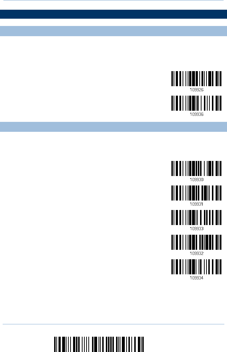
216
Enter Setup
1663 Barcode Scanner User Guide
KEY TYPE & STATUS
KEY TYPE
If “Bluetooth® HID” or “USB HID” is configured for interface, Key Type and Key Status
will then become applicable.
*Normal
Scan Code
KEY STATUS
Decide whether or not to change key status when “Normal Key” is selected for Key Type.
Add Shift
Add Left Ctrl
Add Right Ctrl
Add Left Alt
Add Right Alt

217
Update
Appendix III
Keyboard Wedge
Table
EXAMPLE
KEY TYPE = NORMAL
For example, if you want to program the character “!” as the prefix code:
1) Read the “Configure Prefix” barcode.
2) Read the “Hexadecimal Value” barcode on page 220 for “2” and “1”.
3) Read the “Validate” barcode to complete this setting.
KEY TYPE = SCAN CODE
For example, if you want to program the character “a” (= “1 C” on the sc an code tabl e) as the
prefix code:
1) Read the “Configure Prefix” barcode.
2) Read the “Scan Code” barcode.
3) Read the “Hexadecimal Value” barcode on page 220 for “1” and “C”.
4) Read the “Validate” barcode to complete this setting.
KEY TYPE = NORMAL + KEY STATUS = SHIFT
For example, if you want to program the character “!” (= “Shift” + “1” on keyboard) a s the prefix
code:
1) Read the “Configure Prefix” barcode.
2) Read the “Add Shift” barcode.
3) Read the “Hexadecimal Value” barcode on page 220 for “3” and “1”.
4) Read the “Validate” barcode to complete this setting.
KEY TYPE = NORMAL + KEY STATUS = CTRL
For example, if you want to program “Ctrl+A” and “Ctrl+$” as the prefix code:
1) Read the “Configure Prefix” barcode.
2) Read the “Add Left Ctrl” barcode.
3) Read the “Hexadecimal Value” barcode on page 220 for “4”, “1” (= “A”).
4) Read the “Add Left Ctrl” barcode.
5) Read the “Hexadecimal Value” barcode on page 220 for “2”, “4” (= “$”).
6) Read the “Validate” barcode to complete this setting.

218
Enter Setup
1663 Barcode Scanner User Guide
219
Update
DECIMAL SYSTEM
Decimal
Validate the Values
Appendix IV
NUMERAL SYSTEMS
0
1
2
3
4
5
6
7
8
9
V
alidate
1663 Barcode Scanner User Guide
220
Enter Setup
HEXADECIMAL SYSTEM
Hexadecimal
0
1
2
3
4
5
6
7
8
9
A
B
C
D
E
F

221
Update
Appendix IV Numeral Systems
Validate the Values
ASCII TABLE
0 DLE SP 0 @ P ` p
1 SOH DC1 ! 1 A Q a q
2 STX DC2 " 2 B R b r
3 ETX DC3 # 3 C S c s
4 EOT DC4 $ 4 D T d t
5 ENQ NAK % 5 E U e u
6 ACK SYN & 6 F V f v
7 BEL ETB ' 7 G W g w
8 BS CAN ( 8 H X h x
9 HT EM ) 9 I Y i y
A LF SUB * : J Z j z
B VT ESC + ; K [ k {
C FF FS , < L \ l |
D CR GS - = M ] m }
E SO RS . > N ^ n ~
F SI US / ? O _ o DEL
V
alidate
1663 Barcode Scanner User Guide
222
Enter Setup
ENTERING PIN CODE FOR AUTHENTICATION
USE PRESET PIN
1) In the configuration mode, read the barcode below to use a preset PIN for
authentication.
Use Preset PIN
2) Read one of the barcodes to specify the PIN code, in decimal or hexadecimal.
By default, the PIN code is set to “0000”. Maximum 16 characters are allowed.
Enter PIN in
Hexadecimal…
E
nter PIN in
Decimal…
3) Read the “Decimal Value” barcode on page 219 or the “Hexadecimal Value” barcode
on page 220 for the desired digits or character string.
Read the “Clear PIN Code” barcode first if you need to re-input the PIN code.
Clear PIN Code
4) Read the “Validate” barcode to complete this setting.
223
Update
Appendix IV Numeral Systems
DISABLE AUTHENTICATION OR USE RANDOM PIN
In the configuration mode, read the barcode be low to disable authentication (= No PIN)
or use a random PIN for authentication.
*
No PIN or
use random PIN
Note: When using Bluetooth® HID, some device drivers may not support pre-defined PIN
code for authentication. In this case, make sure you have the scanner set to “No
PIN or u se random PIN” before pairing. While pairing, the host PIN code will be
displayed on the computer screen.
Use Random PIN
When the target device is set to use a random PIN for authentication, wait until the random PIN is
displayed on the target device while pairing, and then input the matching PIN code on the scanner.
Note: Follow the steps below to enter the matching PIN on the scanner. There is no need
to enter the configuration mode!
1) Read one of the barcodes to specify the PIN code, in decimal or hexadecimal.
Enter PIN in
Hexadecimal…
E
nter PIN in
Decimal…
2) Read the “Decimal Value” barcode on page 219 or the “Hexadecimal Value” barcode on page
220 for the desired digits or character string.
Read the “Clear PIN Code” barcode first if you need to re-input the PIN.
Clear PIN Code

1663 Barcode Scanner User Guide
224
Enter Setup
3) Read the “Validate” barcode to complete this setting.
Reject Random PIN Request
When the ra ndom PIN i s displayed on the targ et device while pai ring, you can rej ect the PI N
request by having the scanner read the “Validate” barcode.