CipherLab 1862 Handheld RFID Reader User Manual 1800 RFID Reader
CipherLab Co., Ltd. Handheld RFID Reader 1800 RFID Reader
UserManual.wiki
>
CipherLab
>
1862 User Manual
User Manual.pdf
Navigation menu
Upload a User Manual
Namespaces
Wiki Guide
HTML
PDF
Info
Views
User Manual
Discussion / Help
Navigation
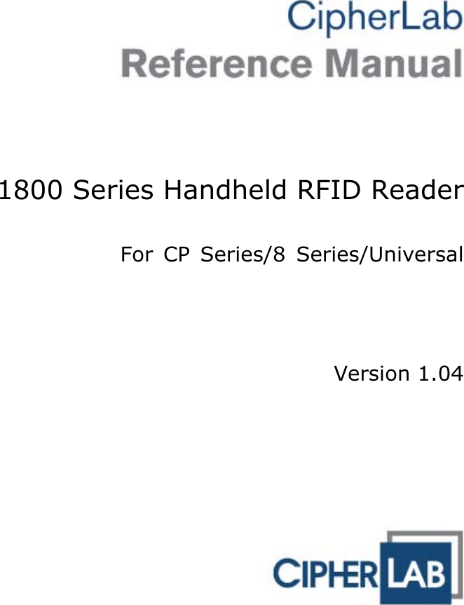

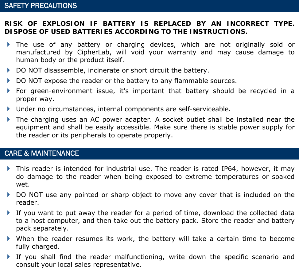

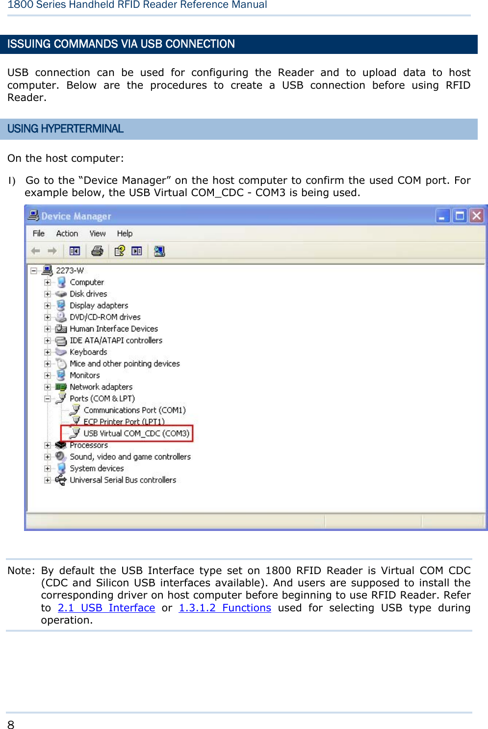
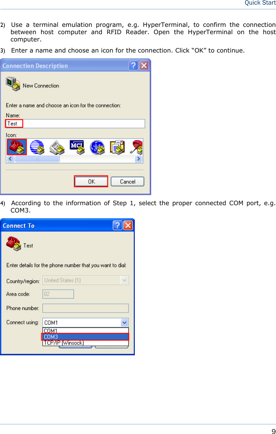
![11 Quick Start 7) In the HyperTerminal window, click on the tool bar to open Properties configuration window, see below. Click “Settings” tab. 8) Click [ASCII Setup] to open ASCII Setup window and some check boxes need to be selected for normalized issuing commands, see below. Click “OK”.](https://usermanual.wiki/CipherLab/1862/User-Guide-2462059-Page-23.png)
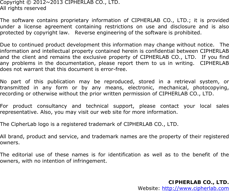
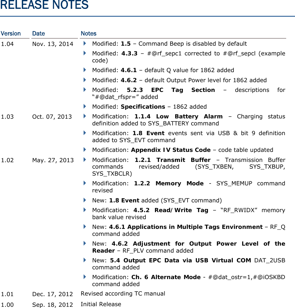
![14 1800 Series Handheld RFID Reader Reference Manual DEFAULT SETTINGS SAVE USER SETTINGS AS DEFAULTS For the RFID Reader to keep the customized settings as user defaults, you must issue “#@sys_svusrtbl” command. Note: After issuing the command, the current settings will be saved as user defaults. Command: #@sys_svusrtbl\r Purpose Save User Defined Setting Response OK\r ERR,[code]\r RESTORE USER/FACTORY DEFAULTS For the RFID Reader to restore the User Defaults, which you have saved earlier, you must issue the “#@sys_ldstbl=1” command. Alternatively, you can also issue the “#@sys_ldstbl=0” command to restore Factory Default. Command: #@sys_ldstbl=[m]\r Purpose Load Default Setting Request #@sys_ldstbl=[m]\r [m]: ‘0’ – Factory Default ‘1’ – User Default Response OK\r ERR,[code]\r Note: Restoring factory defaults may reset any active Bluetooth® connections and erase the MAC address information of the connected device.](https://usermanual.wiki/CipherLab/1862/User-Guide-2462059-Page-26.png)
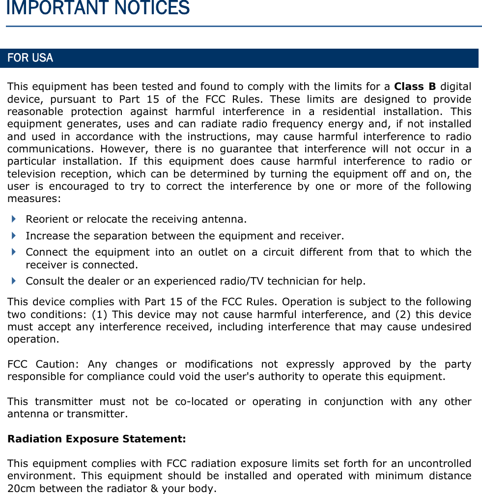
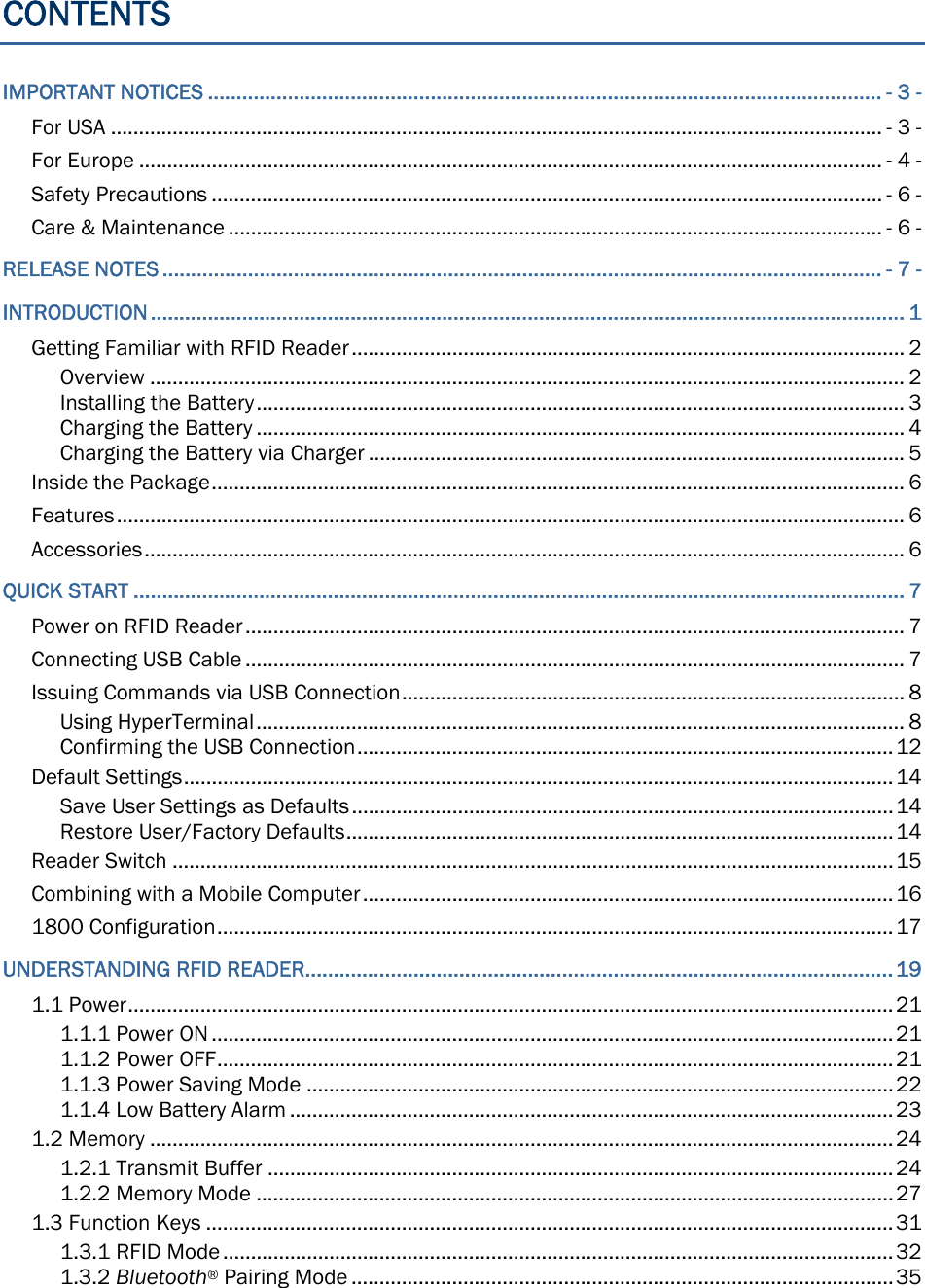
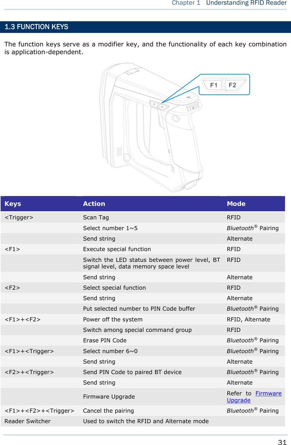
![17 Quick Start 1800 CONFIGURATION You can configure the RFID Reader by issuing commands or 1800Configuration Utility. Serial Command: You may run HyperTerminal.exe on the host computer to send commands to RFID Reader via USB virtual COM or Bluetooth® SPP. The commands are not case sensitive. Example: #@sys_time?<CR> Get the system time information.→ #@sys_time=[Y],[M],[D],[h],[m],[s]<CR> Set the system time. →[Y],[M],[D],[h],[m],[s] are the parameters of system time. Note: A Serial Command consists of Prefix, Text, and Suffix. The prefix consists of “#” and “@”. “?” or “=” is specified to suffix. \r or <CR> is specified for the “Enter” of your keyboard. As a normal command event, it will respond with “OK” or “ERR”. About “ERR”, please refer to Status Code for more information. 1800Configuration Utility: CipherLab supports a Windows®-based Software Utility to allow you to configure RFID Reader easily. For more information, please refer to 1800Configuration User Guide.](https://usermanual.wiki/CipherLab/1862/User-Guide-2462059-Page-29.png)

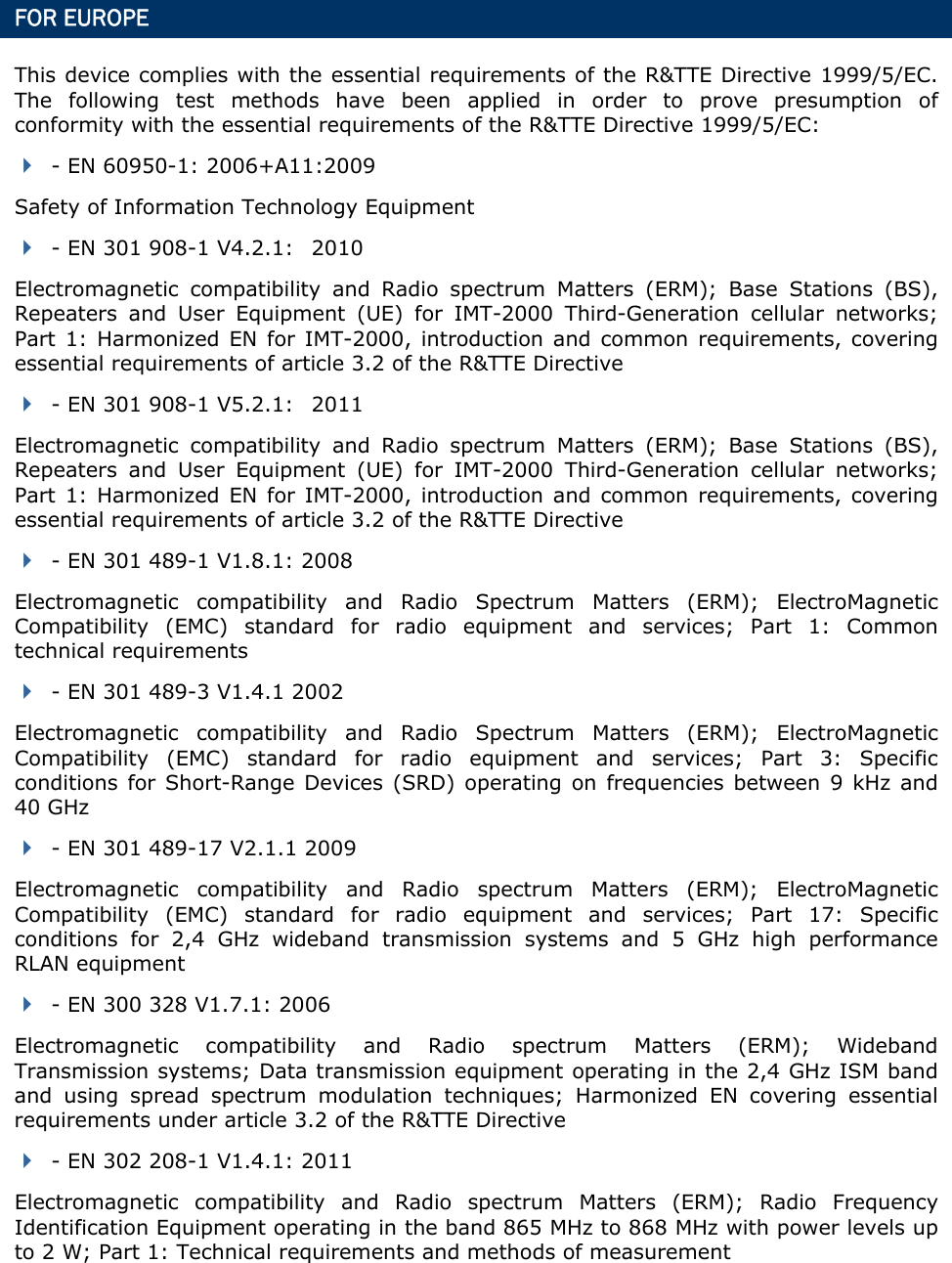
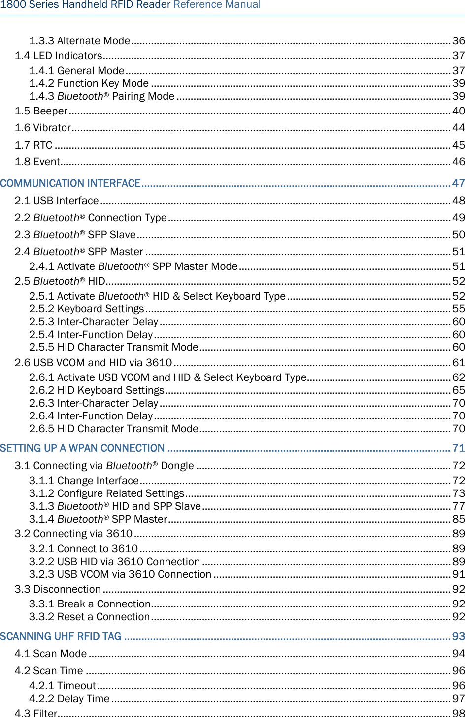
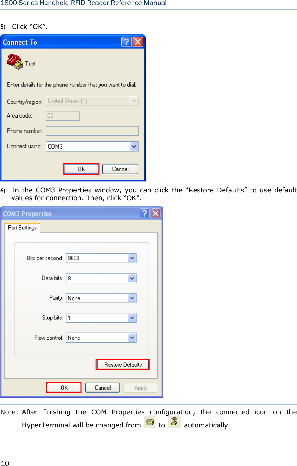
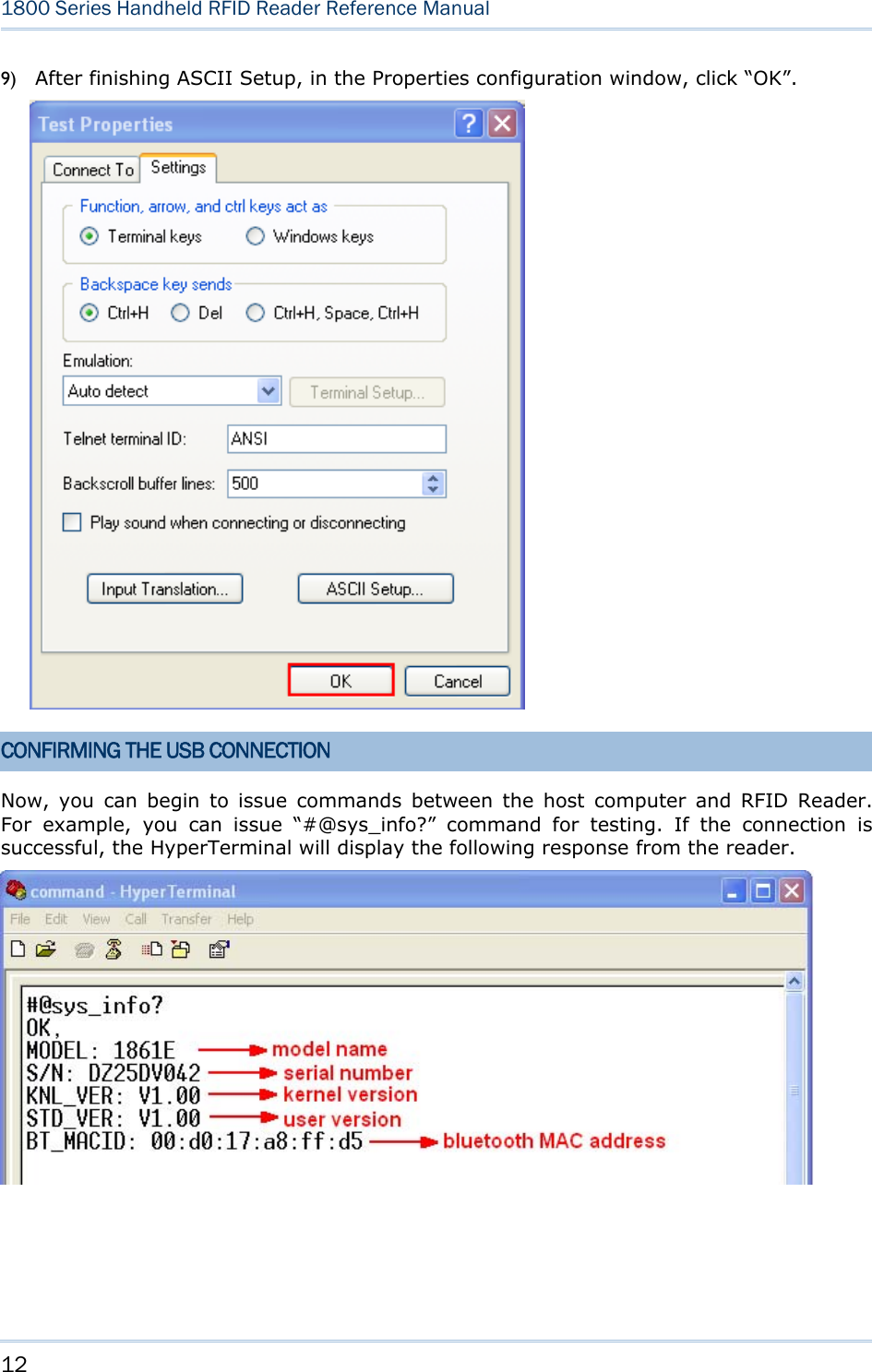
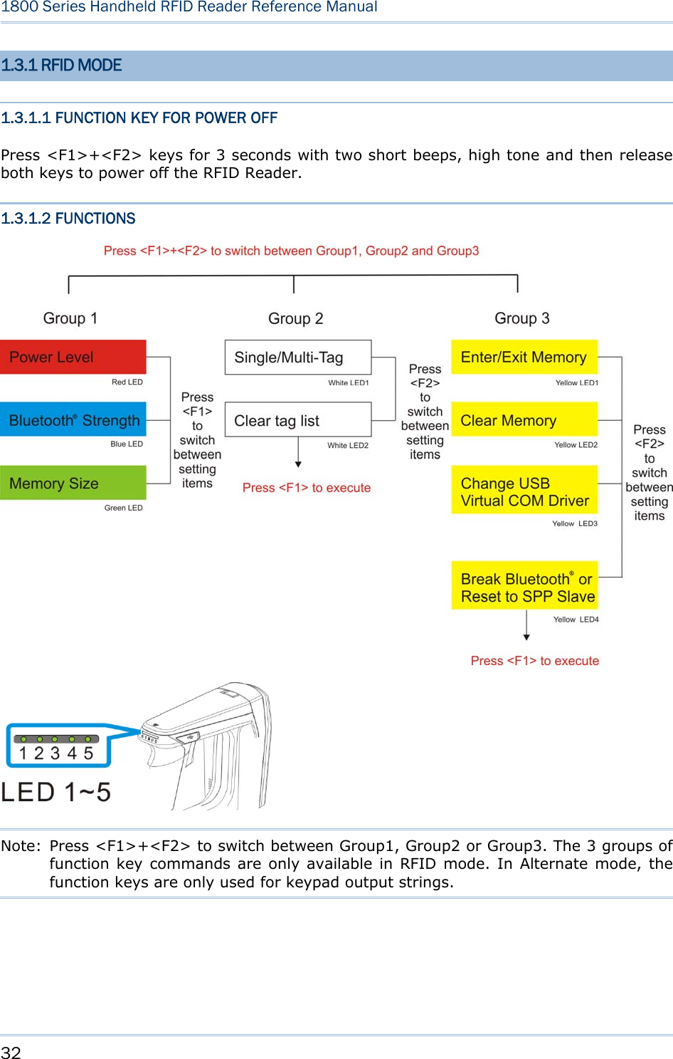
![19 This chapter explains the features and usage of RFID Reader. Before configuring RFID Reader, we will detail the information received when “#@sys_info?” command is issued. Command: #@sys_info?\r Purpose Get System Information Response OK,[m]\r[n]\r[o]\r[p]\r[Q]\r [m]: string that indicates model name “1861E” – Basic UHF type Europe Band “1861U” – Basic UHF type US Band [n]: string that indicates serial number [o]: string that indicates kernel version [p]: string that indicates user version [q]: string that indicates BTMACID ERR,[code]\r Example: Command #@sys_info? Response (s) OK, MODEL: 1861E →model name S/N: DZ25DV042 →serial number KNL_VER: V1.00 →kernel version STD_VER: V1:00 →user version BT_MACID: 00:d0:17:a8:ff:d5 →Bluetooth® MAC address Chapter 1 UNDERSTANDING RFID READER](https://usermanual.wiki/CipherLab/1862/User-Guide-2462059-Page-31.png)
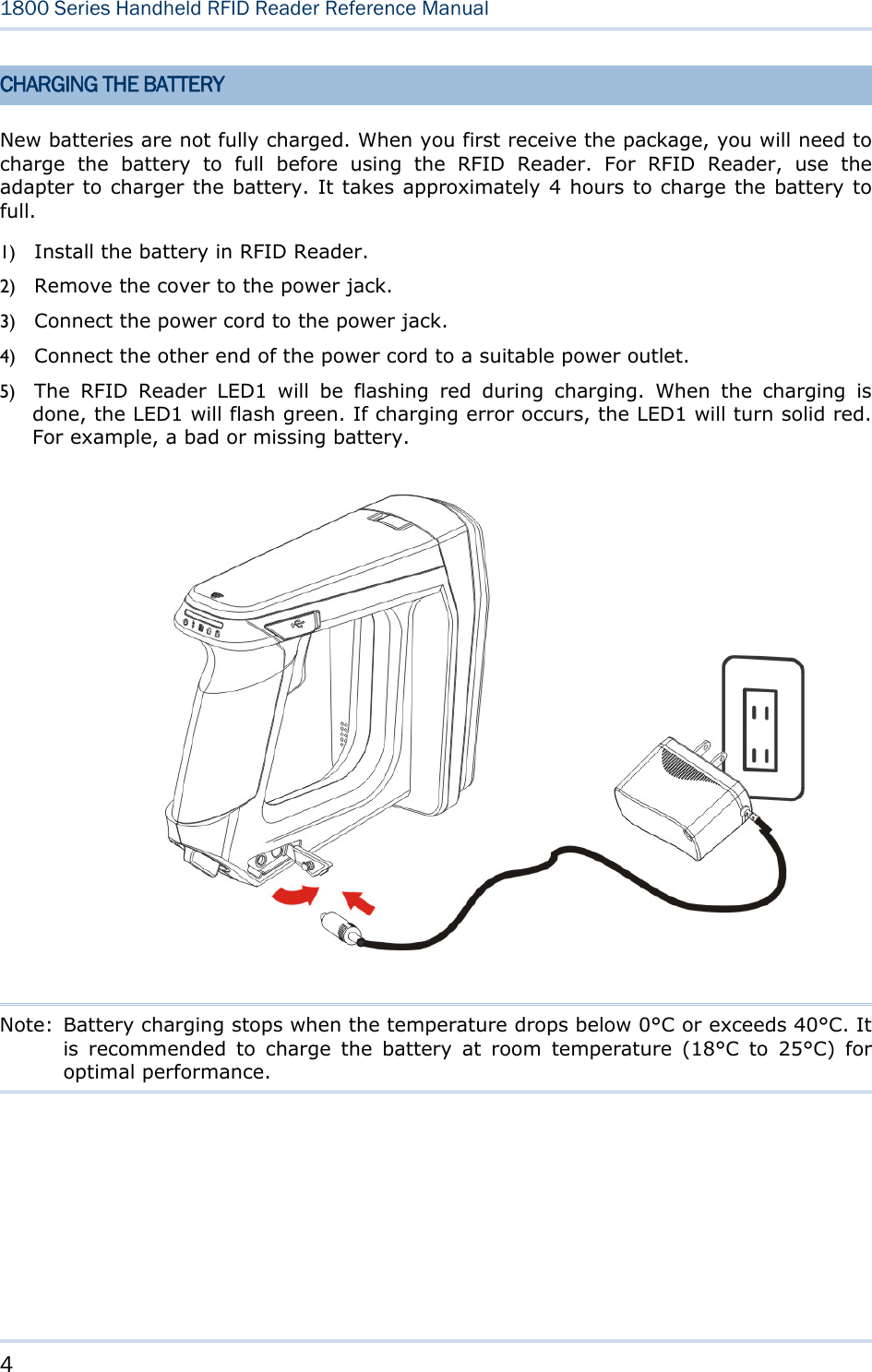
![21 Chapter 1 Understanding RFID Reader 1.1 POWER RFID Reader is powered by a rechargeable 3.7V/2500mAh Li-ion battery pack, and it takes approximately 4 hours to fully charge it via charger or adapter. During normal operation, the RFID Reader can work for up to 10 hours. Warning: The battery cover must be in position. If not, the RFID Reader cannot turn on. For a new battery, make sure it is fully charged before you begin to use it. Always prepare a spare battery, especially when you are working on a non-stop operation. 1.1.1 POWER ON After installing the battery, press the trigger for 2 seconds. The RFID Reader will respond with a long beep (high tone), and LED1 will become solid red for 1 second and go off. 1.1.2 POWER OFF The RFID Reader will stay active at power-on, which may be followed by a transition from full CPU speed to low CPU speed (Power-Saving) to auto shutdown (Auto Power Off). Auto Power Off (1~254 min.; 0= Disable): By default, it is set to automatically shut down after idling 10 minutes. If this feature is not desired, set it to 0. Command: #@sys_tpoff?\r Purpose Get the Delay Time of System Shutdown Response OK,[m]\r (Default m= ‘10’) [m]: ‘0’ ~ ‘254’ (Unit=minute) ERR,[code]\r #@sys_tpoff=[m]\r Purpose Set the Delay Time of System Shutdown Response OK\r ERR,[code]\r](https://usermanual.wiki/CipherLab/1862/User-Guide-2462059-Page-33.png)
![22 1800 Series Handheld RFID Reader Reference Manual Press <F1>+<F2> keys for 3 seconds with two short beeps, high tone and then release both keys to force the RFID Reader to shut down. Alternatively you can also issue command on the host computer described below to power off the RFID Reader. Command: #@sys_off\r Purpose System Shutdown Response OK\r ERR,[code]\r 1.1.3 POWER SAVING MODE Power Saving (1~254 min.; 0= Disable): By default, it is set to idle at full-speed for 2 minutes before it enters power saving mode. If this feature is not desired, set it to 0. Note: The Power Saving setting will not take effect when data is transmitting via Bluetooth® HID or SPP. Command: #@sys_tps?\r Purpose Get the Delay Time of Power Saving Mode Response OK,[m]\r (Default m= ‘2’) [m]: ‘0’ ~ ‘254’ (Unit=minute) ERR,[code]\r #@sys_tps=[m]\r Purpose Set the Delay Time of Power Saving Mode Response OK\r ERR,[code]\r Note: Power Saving will not take effect when one of the following conditions is met: (1) RFID Reader is being configured by the 1800 Configuration Utility. (2) The scanning mode is set to Test Mode. (3) The setting value of Power Saving is greater than Auto Power Off.](https://usermanual.wiki/CipherLab/1862/User-Guide-2462059-Page-34.png)
![23 Chapter 1 Understanding RFID Reader Issue “#@sys_kalive” command to keep system active for a further period of time. Each time with this command issued, the delay time for system shutdown and power saving mode will be reset. Command: #@sys_kalive\r Purpose Keep the System Alive Response OK\r ERR,[code]\r 1.1.4 LOW BATTERY ALARM By default, the battery alarm will beep when the battery charge gets low. In order to prevent data loss, it is advised to replace the battery immediately when hearing two short beeps (high tone). Command: #@sys_battery?\r Purpose Get Remaining Capacity of Battery Response OK,[m],[n]\r [m]: remaining battery capacity. (e.g. 100%) [n]: charging status ‘0’ – not charging ‘1’ – being charged ‘2’ – fully charged ERR,[code]\r #@sys_lbalarm?\r Purpose Get Low Battery Alarm Response OK,[m]\r (Default m= ‘1’) [m]: ‘0’ – Disable ‘1’ – Enable ERR,[code]\r #@sys_lbalarm=[m]\r Purpose Set Low Battery Alarm Response OK\r ERR,[code]\r](https://usermanual.wiki/CipherLab/1862/User-Guide-2462059-Page-35.png)
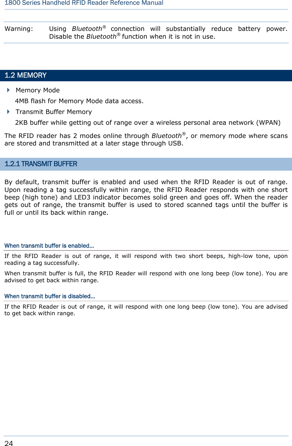
![25 Chapter 1 Understanding RFID Reader Command: #@sys_txben?\r Purpose Get Transmit Buffer Status Response OK,[m],[n]\r ERR,[code]\r #@sys_txben=[m] {,[n]}\r Purpose Enable Transmit Buffer [m]: ‘0’ – Disable (default) ‘1’ – Enable ‘2’ – Enable passive transmit buffer [n]: ‘0’ – Keep data until getting “clear buffer” command ‘1’ – Automatically clear the buffer after data sent (default) [n] exists only when [m] is set to 2. When [m] is set to 0 or 1, [n] will be reset to default. Response OK\r ERR,[code]\r #@sys_txbdly?\r Purpose Get Transmit Buffer Delay Response OK,[m]\r ERR,[code]\r #@sys_txbdly=[m]\r Purpose Set Transmit Buffer Delay Request [m] Send TX Buffer Delay ‘0’ 0 (default) ‘1’ 250 ms ‘2’ 500 ms ‘3’ 1 sec ‘4’ 2 sec ‘5’ 3 sec ‘6’ 5 sec ‘7’ 8 sec Response OK\r ERR,[code]\r](https://usermanual.wiki/CipherLab/1862/User-Guide-2462059-Page-37.png)
![26 1800 Series Handheld RFID Reader Reference Manual #@sys_txbup\r Purpose Inquire Data from Transmit Buffer Response OK\r //command received [m]\r //data string EOT,[n]\r //End of Transmit. [n] indicates the total data count in buffer. ERR,[code]\r #@sys_txbclr\r Purpose Clear Transmit Buffer Response OK\r ERR,[code]\r](https://usermanual.wiki/CipherLab/1862/User-Guide-2462059-Page-38.png)
![27 Chapter 1 Understanding RFID Reader 1.2.2 MEMORY MODE The RFID Reader includes 4MB flash memory for data storage when the reader operates in memory mode. When the RFID Reader gets into memory mode, the current Bluetooth® connection with the host is disabled. Warning: Bluetooth® connection is not available in the memory mode. STATUS Confirm the memory size by issuing “#@sys_memsize?” command. Command: #@sys_memen?\r Purpose Get Memory Mode Status Response OK,[m]\r (Default m= ‘0’) [m]: ‘0’ – Disable ‘1’ – Enable ERR,[code]\r #@sys_memen=[m]\r Purpose Set Memory Mode Response OK\r ERR,[code]\r Note: You can also enter/exit memory mode by pressing function keys. Refer to 1.3.1.2 Functions. #@sys_memsize?\r Purpose Get Free Memory Size Response OK,[m]\r (Max. 4072) [m]: Free Memory Size string in KB ERR,[code]\r](https://usermanual.wiki/CipherLab/1862/User-Guide-2462059-Page-39.png)
![28 1800 Series Handheld RFID Reader Reference Manual DATA DELAY You may set a delay time between each data record while transmitting data back to the host computer. Command: #@sys_memdly?\r Purpose Get Data Transmission Delay Response OK,[m]\r (Default m= ‘0’) [m]: ‘0’~’7’ Data Transmission Delay Value Delay ‘0’ 0 ms ‘1’ 250 ms ‘2’ 500 ms ‘3’ 1 sec ‘4’ 2 sec ‘5’ 3 sec ‘6’ 5 sec ‘7’ 8 sec ERR,[code]\r #@sys_memdly=[m]\r Purpose Set Data Transmission Delay Response OK\r ERR,[code]\r](https://usermanual.wiki/CipherLab/1862/User-Guide-2462059-Page-40.png)
![29 Chapter 1 Understanding RFID Reader SEND DATA To transmit the data to the host immediately, use the following command “#@sys_memup”. Command: #@sys_memup\r Purpose Upload Memory Data Response OK\r //command received [m]\r //data string EOT,[n]\r //End of Transmit. [n] indicates the total data count. ERR,[code]\r CLEAR MEMORY Even though data has been sent back to the host, the flash memory is still occupied with the scanned data which can be uploaded repeatedly unless you erase the memory by issuing “#@sys_memclr” command to clear memory. Command: #@sys_memclr\r Purpose Clear Memory Response OK\r ERR,[code]\r](https://usermanual.wiki/CipherLab/1862/User-Guide-2462059-Page-41.png)
![30 1800 Series Handheld RFID Reader Reference Manual Example: Command #@sys_memsize? →get current memory size Response (s) OK, 4072 Command #@sys_memen=1 →enter memory mode Response (s) OK Command #@sys_memdly=4 →set the delay time of data transmission to 2 sec. Response (s) OK Command #@sys_memup →upload memory data Response (s) 1. 2012-04-18 30003430333130303132303030304221 2. 2012-04-18 30003430333130303132303030304221 3. 2012-04-18 30003430333130303132303030304221 OK Command #@sys_memclr →clear memory size Response (s) OK ] 2sec.→ ] 2sec.→](https://usermanual.wiki/CipherLab/1862/User-Guide-2462059-Page-42.png)
![38 1800 Series Handheld RFID Reader Reference Manual Note: You can configure the good read LED3 status (disable/enable) and duration (ranging from 1 to 254 in units of 10 milliseconds) by command. When you set the LED3 feedback as disable, the LED3 will always be off. GOOD READ LED STATUS You may configure the LED3 status for a feedback about good read. Command: #@sys_leden?\r Purpose Get Good Read LED Status Response OK,[m]\r (Default m= ‘1’) [m]: ‘0’ – Disable ‘1’ – Enable ERR,[code]\r #@sys_leden=[m]\r Purpose Set LED Good Read Status Response OK\r ERR,[code]\r GOOD READ LED DURATION For a good read for LED3, you may configure the duration time. Command: #@sys_leddu?\r Purpose Get Good Read LED Duration Response OK,[m]\r (Default m= ‘4’) [m]: Duration=‘1’ ~ ‘254’ ERR,[code]\r #@sys_leddu=[m]\r Purpose Set LED Duration Response OK\r ERR,[code]\r](https://usermanual.wiki/CipherLab/1862/User-Guide-2462059-Page-50.png)
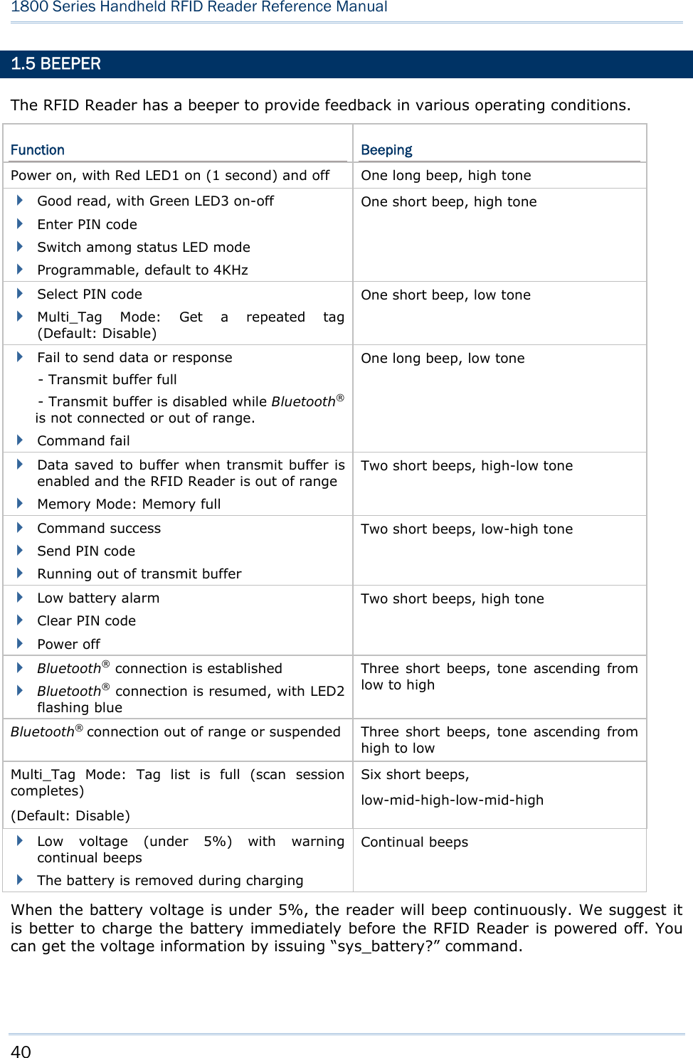
![41 Chapter 1 Understanding RFID Reader The commands below describe the beeper related configurations: VOLUME There are four volume levels defined to beeping setting. Command: #@sys_bpvol?\r Purpose Get Beeper Volume Response OK,[m]\r (Default m= ‘High’) [m]: Volume ‘0’ Mute ‘1’ Low ‘2’ Medium ‘3’ High ERR,[code]\r #@sys_bpvol=[m]\r Purpose Set Beeper Volume Response OK\r ERR,[code]\r COMMAND BEEP By default, this function is disabled. Command: #@sys_cmdbp?\r Purpose Get Status of Command Indicating Beep Response OK,[m]\r (Default m= ‘0’) [m]: ‘0’ – Disable ‘1’ – Enable ERR,[code]\r #@sys_cmdbp=[m]\r Purpose Set Command indicating Beep Response OK\r ERR,[code]\r](https://usermanual.wiki/CipherLab/1862/User-Guide-2462059-Page-53.png)
![42 1800 Series Handheld RFID Reader Reference Manual GOOD READ You have to enable the beeping function when you want to get audio feedback from RFID Reader. Command: #@sys_grdbp?\r Purpose Get Status of Good-Read Beep Response OK,[m]\r (Default m= ‘1’) [m]: ‘0’ – Disable ‘1’ – Enable ERR,[code]\r #@sys_grdbp=[m]\r Purpose Set Status of Good-Read Beep Response OK\r ERR,[code]\r FREQUENCY By default, the frequency for a beeper is configured to 4KHz. This function is available when Good-Read beep is enabled. Command: #@sys_grdbf?\r Purpose Get Beeper Frequency Response OK,[m]\r (Default m= ‘1’) [m]: Frequency ‘0’ 8 kHz ‘1’ 4 kHz ‘2’ 2 kHz ‘3’ 1 kHz ERR,[code]\r #@sys_grdbf=[m]\r Purpose Set Beeper Frequency Response OK\r ERR,[code]\r](https://usermanual.wiki/CipherLab/1862/User-Guide-2462059-Page-54.png)
![43 Chapter 1 Understanding RFID Reader DURATION You can configure the beeping duration to shortest, short, longer or longest. This function is available when Good-Read beep is enabled. Command: #@sys_grdbdu?\r Purpose Get Beeper Duration Response OK,[m]\r (Default m= ‘Shortest’) [m]: Duration ‘0’ Shortest ‘1’ Short ‘2’ Longer ‘3’ Longest ERR,[code]\r #@sys_grdbdu=[m]\r Purpose Set Beeper Duration Response OK\r ERR,[code]\r Note: When you set the volume of beeper to mute, there will be no audio feedback.](https://usermanual.wiki/CipherLab/1862/User-Guide-2462059-Page-55.png)
![44 1800 Series Handheld RFID Reader Reference Manual 1.6 VIBRATOR The RFID Reader has a built-in vibrator, which can be issued command for feedback. This can be helpful when working in noisy environments. For good read/write, the vibrator will vibrate for 1 second then stop. The vibration and duration are programmable. STATUS RFID Reader supports a vibration option that you can enable/disable by issuing “#@sys_viben=” command. Command: #@sys_viben?\r Purpose Get Vibrator Status Response OK,[m]\r (Default m= ‘0’) [m]: ‘0’ – Disable ‘1’ – Enable ERR,[code]\r #@sys_viben=[m]\r Purpose Set Vibrator Status Response OK\r ERR,[code]\r DURATION By default, a good read vibration stays on for 1 second. Specify a value, ranging from 1 to 254 in units of 100 milliseconds. Command: #@sys_vibdu?\r Purpose Get Vibrator Duration Response OK,[m]\r (Default m= ‘10’) [m]: Duration=‘1’ ~ ‘254’ ERR,[code]\r](https://usermanual.wiki/CipherLab/1862/User-Guide-2462059-Page-56.png)
![45 Chapter 1 Understanding RFID Reader #@sys_vibdu=[m]\r Purpose Set Vibrator Duration Response OK\r ERR,[code]\r 1.7 RTC RFID Reader supports a Real Time Clock to keep track of the current time. Command: #@sys_time?\r Purpose Get System Clock Response OK,[Y],[M],[D],[h],[m],[s]\r [Y]: ‘00’ ~ ‘99’ [M]: ‘01’ ~ ‘12’ [D]: ‘01’ ~ ‘31’ [h]: ‘00’ ~ ‘23’ [m]: ‘00’ ~ ‘59’ [s]: ‘00’ ~ ‘59’ ERR,[code]\r #@sys_time=[Y],[M],[D],[h],[m],[s]\r Purpose Set System Clock Response OK\r ERR,[code]\r Example: Command #@sys_time? →get current system time Response (s) OK,12,05,10,10,36,05 →date=2012/5/10, time=10:36 05 Command #@sys_time=12,06,20,12,50,00 →set system date and time to 2012/6/20 12:50 00 Response (s) OK](https://usermanual.wiki/CipherLab/1862/User-Guide-2462059-Page-57.png)
![46 1800 Series Handheld RFID Reader Reference Manual 1.8 EVENT Users can retrieve the current event settings and set them by purpose. Command: #@sys_evt?\r Purpose Get Current Event Settings Response OK,[m],[n]\r m: The event setting is shown in 4-digit hexadecimal. Refer to the Event table below. n: ‘0’ – Disable (default) ‘1’ – Enable that events can be sent via USB if BT is not connected. Bit Default Meaning 0 1 System will enter PS mode after this event. 1 1 System will shut down after this event. 2 1 Bluetooth will be disconnected after this event. 3 1 System setting is changed (by command via USB or FN key), which is indicated by sending the Group Code and Command Code in the Event packet. 4 0 Low Battery Alarm. 1800 sends this event every 30 seconds if battery voltage is lower than 3.6V. 5 1 Mode switching between Alternate and RFID. 6 1 RFID failure (initial failure or no response during operating) 7 0 No tag is found when scan session times out in single mode 8 0 scan session completes in multi-tag mode (new tag amount is equal to multi-tag counter) 9 0 Memory Mode/BT Mode switched 15~10 0 Reserved ERR,[code]\r Remark For example, Event code 001C (0000 0000 0001 1100) means “Low Battery” alarm, “System Setting Changed” and “Bluetooth Will Be Disconnected” events occur. #@sys_evt=[m]{,[n]}\r Purpose Set Event Settings Response OK\r ERR,[code]\r #@evt[m]{,[n]}\r Response m: event code n: command code which appears only when bit 3 of the event code is set.](https://usermanual.wiki/CipherLab/1862/User-Guide-2462059-Page-58.png)
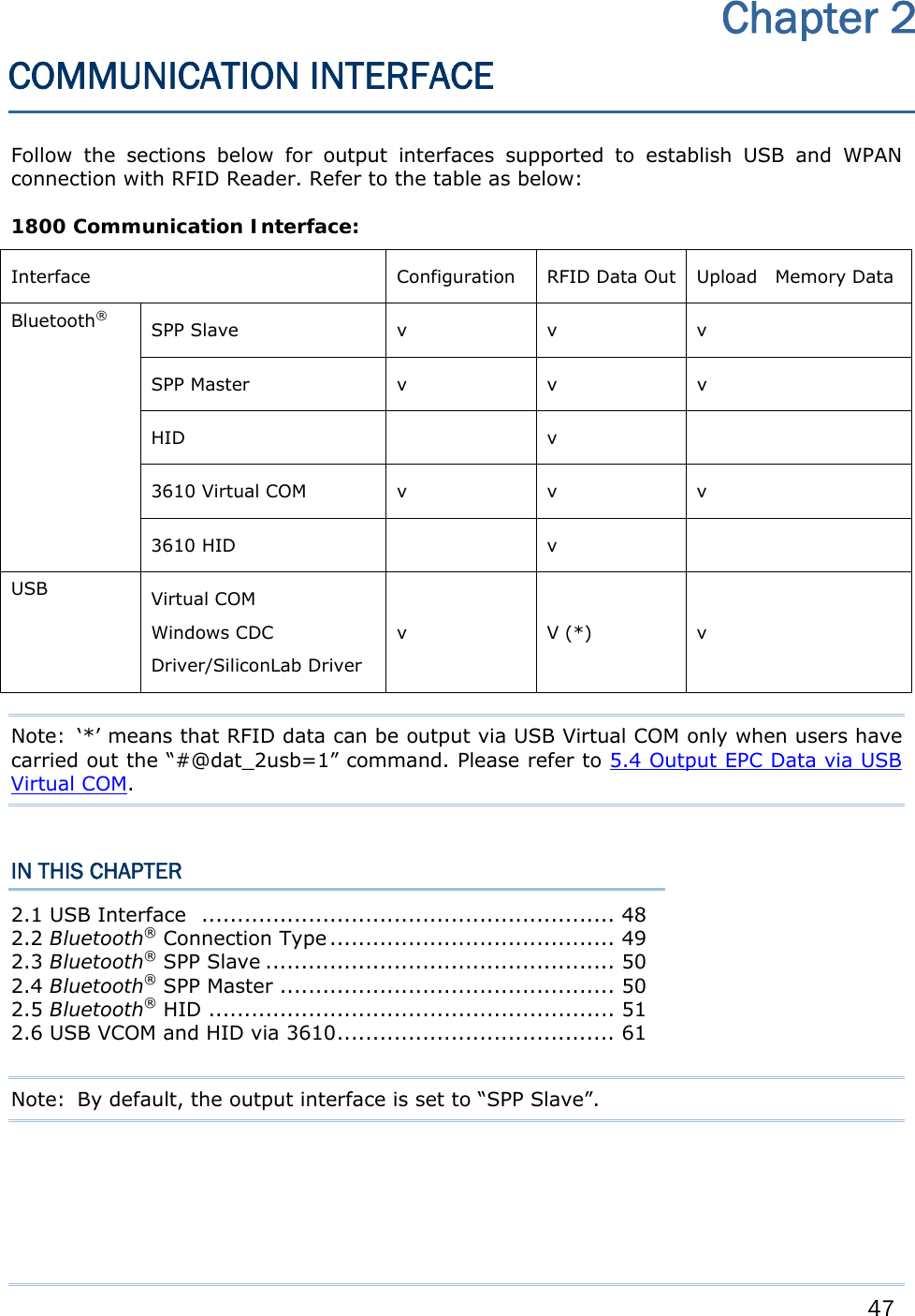
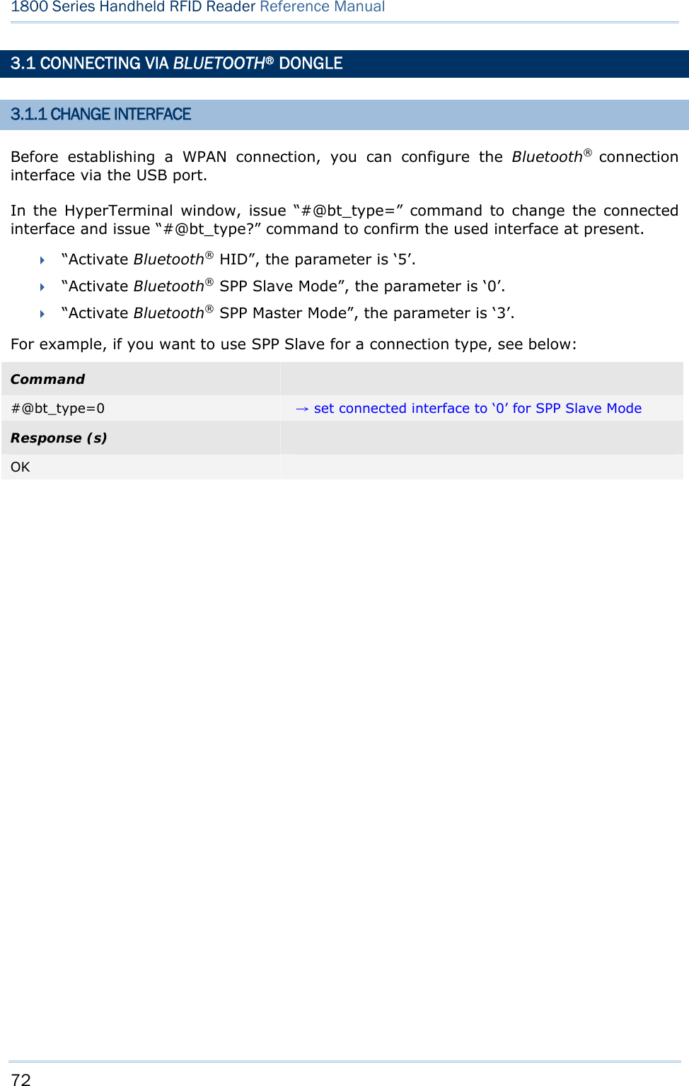
![48 1800 Series Handheld RFID Reader Reference Manual 2.1 USB INTERFACE Create a connection between RFID Reader and host computer; you have to select the available USB interface type by the “#@usb_type=” command. You can also use the function keys to switch between the USB interface types, refer to 1.3.1.2 Functions. Command: #@usb_type?\r Purpose Get USB Interface Type Response OK,[m]\r (Default m=‘127’) [m]: USB Type ‘127’ – Virtual COM CDC ‘128’ – Virtual COM (Silicon Lab driver) ERR,[code]\r #@usb_type=[m]\r Purpose Set USB Interface Response OK\r ERR,[code]\r](https://usermanual.wiki/CipherLab/1862/User-Guide-2462059-Page-60.png)
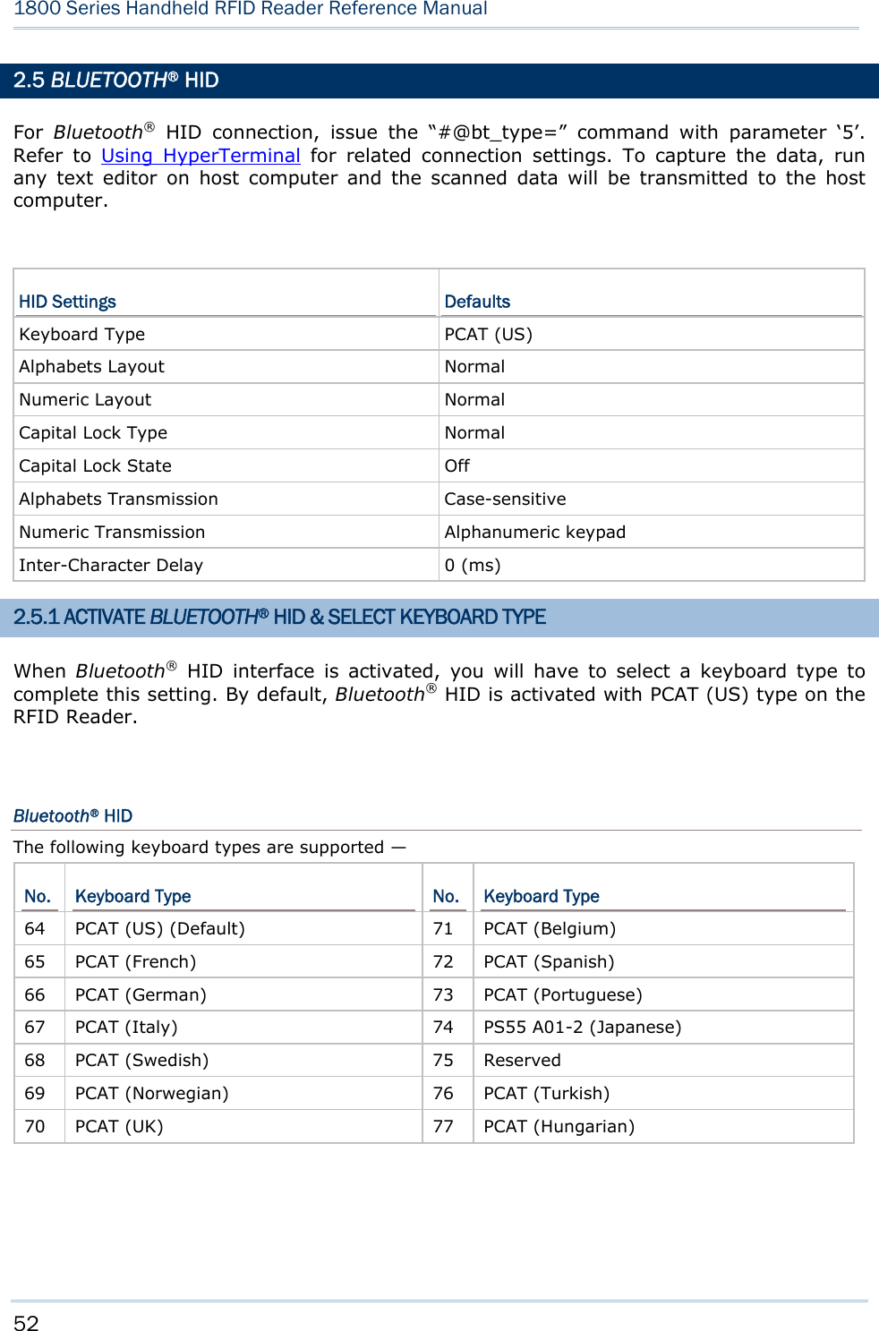
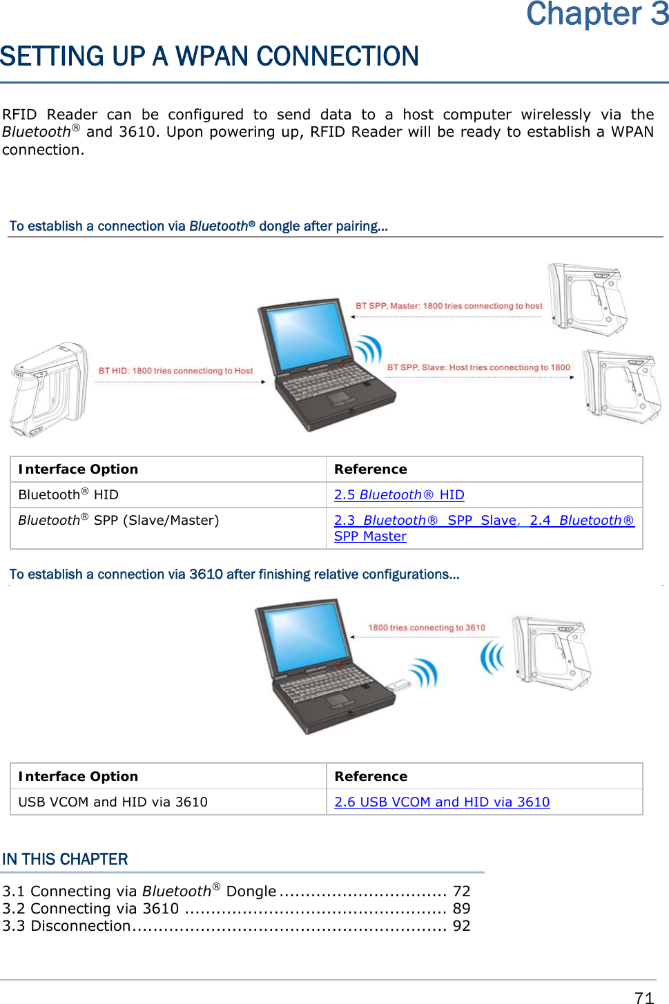
![49 Chapter 2 Communication Interface 2.2 BLUETOOTH® CONNECTION TYPE 1800 RFID reader is capable of various Bluetooth® connection for different target requirements. By default, the connection type is configured to “SPP Slave”. Command: #@bt_type?\r Purpose Get Bluetooth® Interface Type Response OK,[m]\r (Default m= ’0’) [m]: Bluetooth® TYPE Bluetooth® Type Description Read only / R/W ‘0’ SPP Slave R/W ‘3’ SPP Master R/W ‘5’ HID R/W ‘6’ 3610 Read only ERR,[code]\r #@bt_type=[m]\r Purpose Set Bluetooth® Interface Type Response OK\r ERR,[code]\r](https://usermanual.wiki/CipherLab/1862/User-Guide-2462059-Page-61.png)
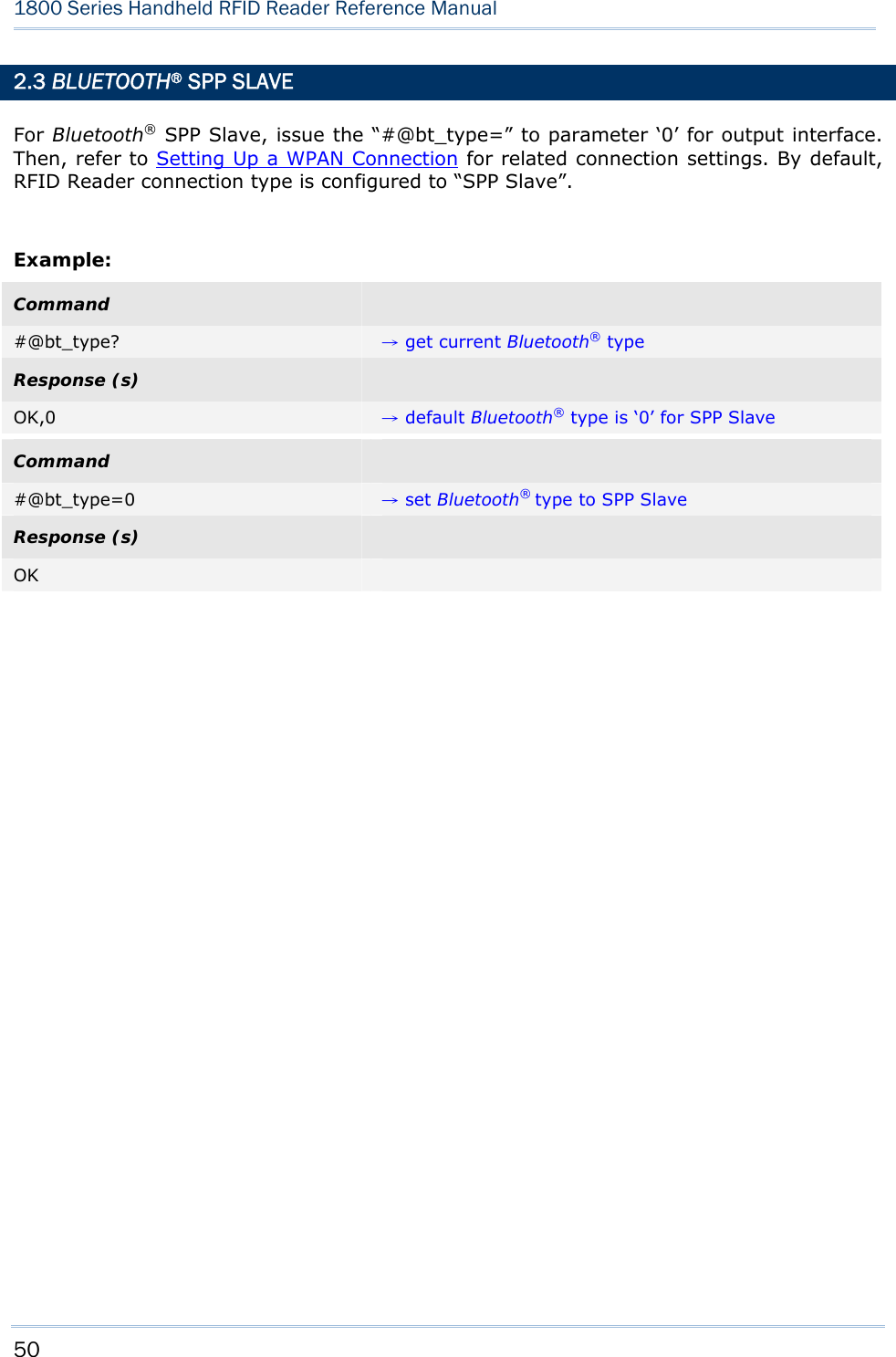
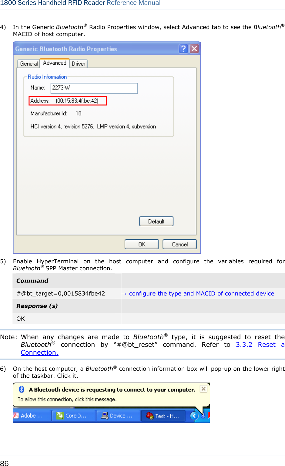
![51 Chapter 2 Communication Interface 2.4 BLUETOOTH® SPP MASTER As a SPP master device, RFID Reader will be able to resume connection with the host computer upon powering on again, as long as the host application is running. If RFID Reader fails to resume connection, it will try every 5 seconds to re-connect to the host computer unless you issue the “#@bt_reset” or “#@sys_ldstbl=” command. For Bluetooth® SPP Master Connection, refer to 3.1.4 Bluetooth® SPP Master. Note: In SPP Master Mode, RFID Reader has to connect within the specified period of time (2 minutes by default). During the connection, the RFID Reader will enter Power Saving Mode. It will automatically power off when the Auto Shutdown time is reached. Refer to 1.1 Power. 2.4.1 ACTIVATE BLUETOOTH® SPP MASTER MODE How to connect with the target machine? Two parameters are necessary using “#@bt_target=” command for SPP Master connection. One is to configure connection type as SPP Master; the other is MAC ID of the target machine. Command: #@bt_target?\r Purpose Get Bluetooth® Target Machine Response OK,[m],[n]\r [m]: Bluetooth® Type, ‘0’ – SPP Master, ‘1’ – 3610 [n]: MACID of target Machine or S/N of 3610 ERR,[code]\r #@bt_target=[m],[n]\r Purpose Set Bluetooth® Target Machine Response OK ERR,[code] Exit SPP Master Mode To stop such re-connection, you can issue the “#@bt_reset” command so that the current connection record (= MAC ID) will be cleared. Connection type will also be restored to default (SPP Slave). Go through the whole process in Setting Up a WPAN Connection to establish a new WPAN connection.](https://usermanual.wiki/CipherLab/1862/User-Guide-2462059-Page-63.png)
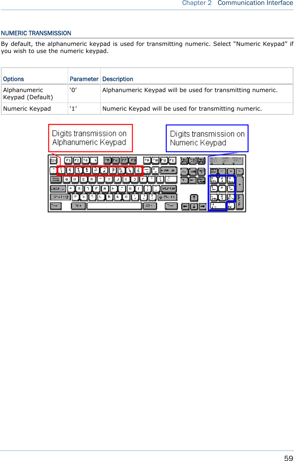
![53 Chapter 2 Communication Interface Command: #@bt_hididx?\r Purpose Get Bluetooth® HID Parameter Index Response OK,[m]\r [m]: Parameter Index [m] Description Valid Parameters ‘0’ HID KBD Type ‘64’~ ‘77’ (Default m=‘64’) ‘3’ Inter-function Delay ‘0’ ~ ‘254’ (Default m=‘0’) ‘4’ Inter-character Delay ‘0’ ~ ‘254’ (Default m=‘0’) ‘5’ Caps Lock State ‘0’ – OFF (Default) ‘1’ – ON ‘2’ – Auto ‘7’ Alphabets Transmission ‘0’ – Case Sensitive (Default) ‘1’ – Ignore Case ‘8’ Digits Transmission ‘0’ – Alpha Numeric Keypad (Default) ‘1’– Numeric Keypad ‘9’ Digits Position ‘0’ – Normal (Default) ‘1’– Lower Row ‘2’– Upper Row ‘10’ Keyboard Layout ‘0’ – Normal (Default) ‘1’ – AZERTY ‘2’ – QWERTZ ‘12’ HID Character Transmit Mode ‘0’ – Batch Processing (Default) ‘1’ – By Character ERR,[code]\r #@bt_hididx=[m]\r Purpose Set Bluetooth® HID Parameter Index Response OK\r\r ERR,[code]](https://usermanual.wiki/CipherLab/1862/User-Guide-2462059-Page-65.png)
![54 1800 Series Handheld RFID Reader Reference Manual #@bt_hidpr?\r Purpose Get Bluetooth® HID Parameter Response OK,[m]\r [m]: Parameter ERR,[code]\r #@bt_hidpr=[m]\r Purpose Set Bluetooth® HID Parameter Response OK\r ERR,[code]\r Example: Command #@bt_type=5 →change connected interface to BT HID Response (s) OK Command #@bt_hididx=0 →enter HID KBD type configuration Response (s) OK Command #@bt_hidpr=64 →set PCAT (US) for KBD type Response (s) OK](https://usermanual.wiki/CipherLab/1862/User-Guide-2462059-Page-66.png)
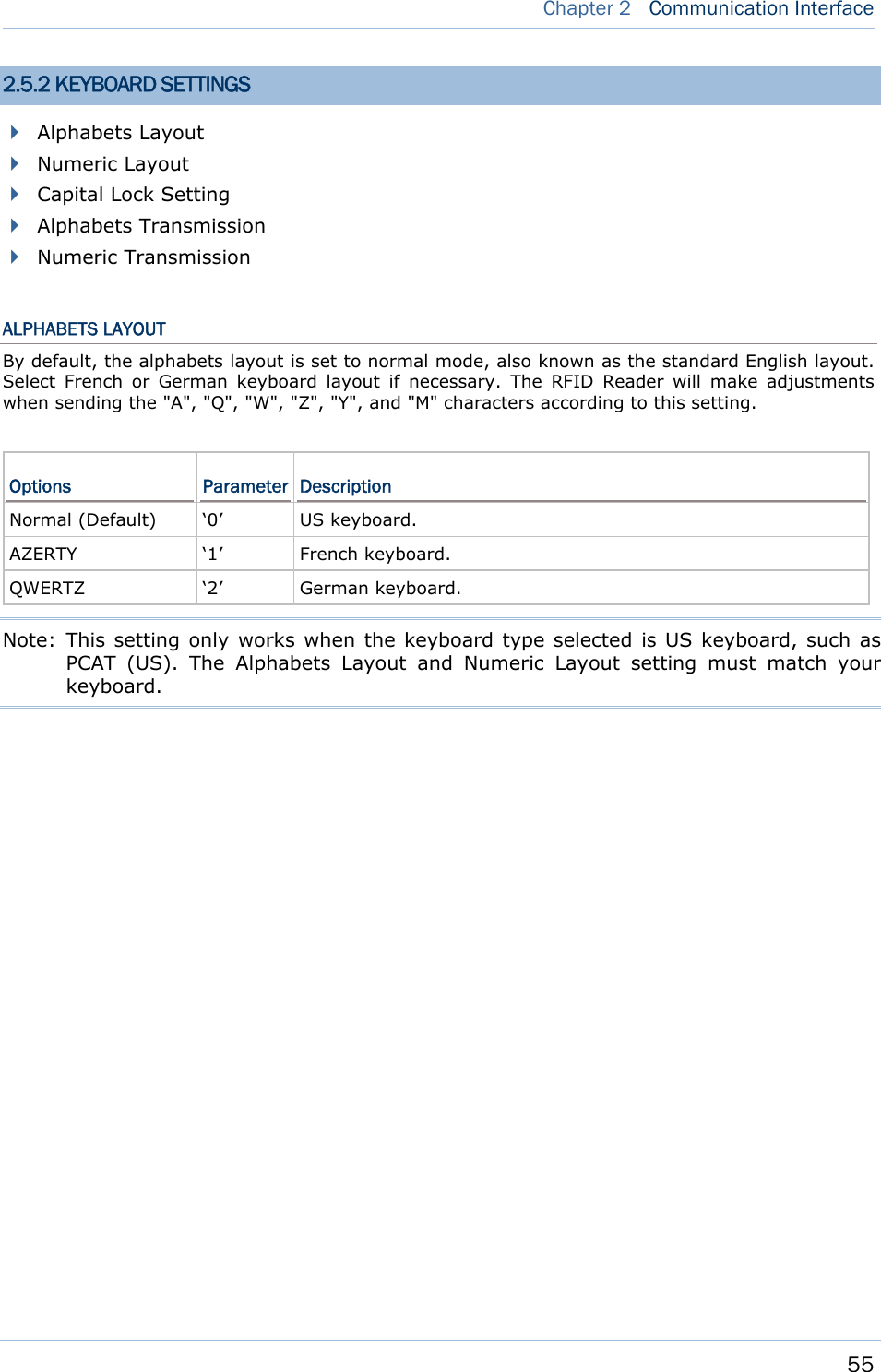
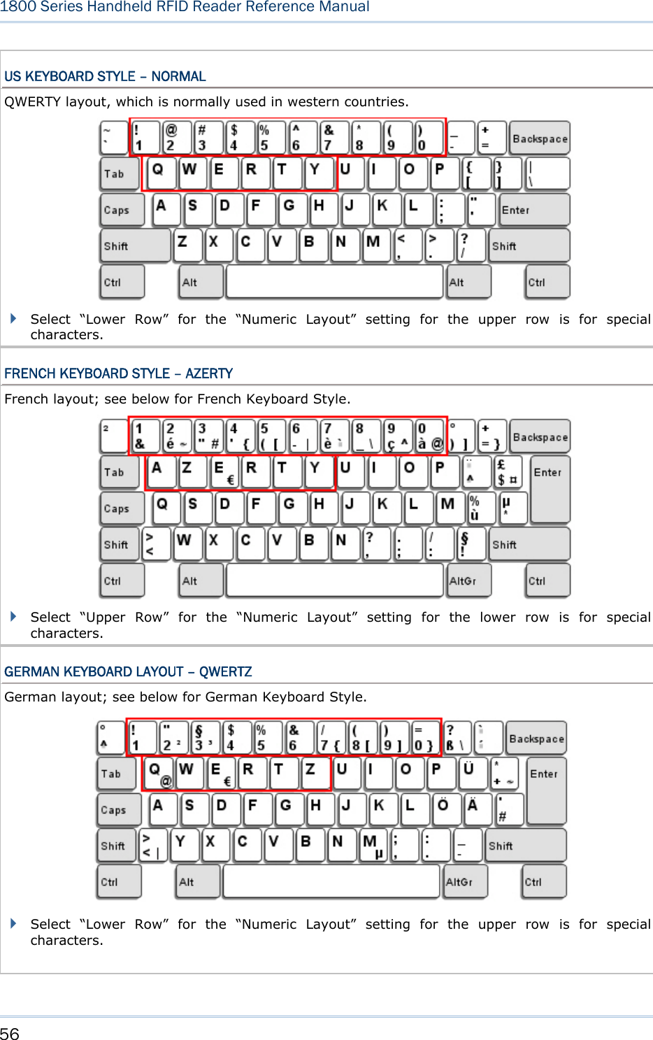
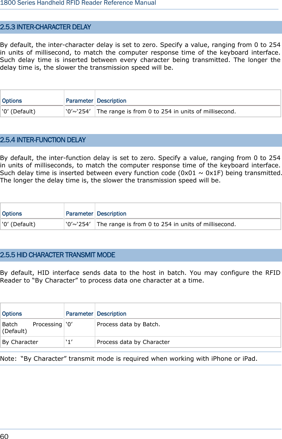
![57 Chapter 2 Communication Interface NUMERIC LAYOUT Select a proper layout that matches the alphabets layout. The RFID Reader will make adjustments according to this setting. Options Parameter Description Normal (Default) ‘0’ Depend on the [Shift] key or [Shift Lock] setting. Lower Row ‘1’ For QWERTY or QWERTZ keyboard. Upper Row ‘2’ For AZERTY keyboard. Note: This setting is to be used with the Character Substitution setting when support to certain keyboard types (languages) is unavailable but required. CAPITAL LOCK SETTING In order to send the alphabets with correct case, the RFID Reader needs to know the status of Caps Lock on the keyboard. Incorrect settings may result in reversed case of the alphabets being transmitted. Options Parameter Description Capital Lock OFF (Default) ‘0’ Assuming that the status of Caps Lock on the keyboard is OFF, transmitted characters are exactly the same as in the tag (when "case-sensitive" is selected for Alphabets Transmission). Capital Lock ON ‘1’ Assuming that the status of Caps Lock on the keyboard is ON, transmitted characters are exactly the same as in the tag (when "case-sensitive" is selected for Alphabets Transmission). Refer to the Capital Lock Type above. Auto Detection ‘2’ The RFID Reader will automatically detect the status of Caps Lock on the keyboard before data is transmitted; transmitted characters are exactly the same as in the tag (when "case-sensitive" is selected for Alphabets Transmission).](https://usermanual.wiki/CipherLab/1862/User-Guide-2462059-Page-69.png)
![58 1800 Series Handheld RFID Reader Reference Manual ALPHABETS TRANSMISSION By default, the alphabets transmission is case-sensitive, meaning that the alphabets will be transmitted according to their original case, the status of Caps Lock on the keyboard, as well as the Capital Lock setting. Select [Ignore Case] to have alphabets transmitted according to the status of Caps Lock on the keyboard only. Options Parameter Description Case Sensitive (Default) ‘0’ Alphabets will be transmitted according to the original case. Ignore Case ‘1’ Alphabets will be transmitted according to the status of Caps Lock on the keyboard only.](https://usermanual.wiki/CipherLab/1862/User-Guide-2462059-Page-70.png)
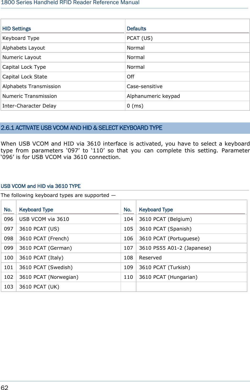
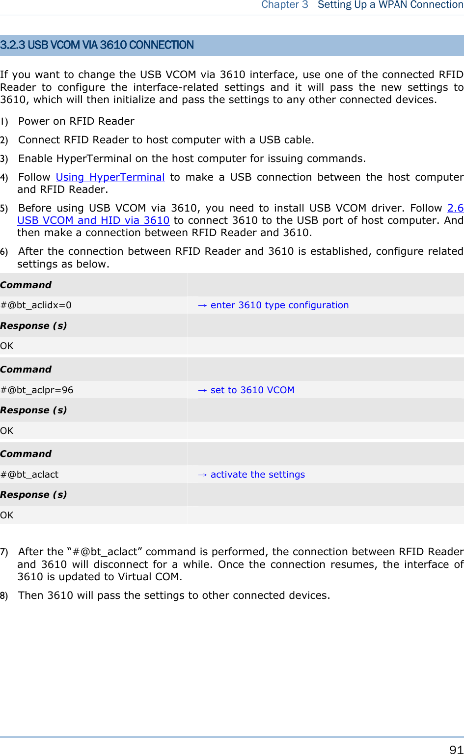
![61 Chapter 2 Communication Interface 2.6 USB VCOM AND HID VIA 3610 Note: If you are using USB VCOM for the first time, you must install its driver from the CD-ROM. Driver version 5.4 or later is required. Please remove older versions! Refer to 2.1 USB Interface. For USB VCOM and HID via 3610, connect 3610 to the USB port of host computer, and then connect RFID Reader to 3610 via Bluetooth®. Before the Bluetooth® connection between 1800 and 3610 is able to be established, users have to connect a USB cable between them to tell 1800 the information about 3610 via the “bt_target” command. To capture the data, run any text editor on host computer. The scanned data will be transmitted to the host computer. How to connect with the 3610? Two parameters are necessary using “#@bt_target” command to make a connection with 3610. One is to configure connect type as 3610; and the other is serial No. of the target machine. Command: #@bt_target?\r Purpose Get Bluetooth® Target Machine Response OK,[m],[n]\r [m]: Bluetooth® Type, ‘0’ – SPP Master, ‘1’ – 3610 [n]: MACID of target Machine or S/N of 3610 ERR,[code]\r #@bt_target=[m],[N]\r Purpose Set Bluetooth® Target Machine Response OK\r ERR,[code]\r Example: Command #@bt_target=1,BS9001346 →set target to 3610 with S/N:BS9001346 Response (s) OK](https://usermanual.wiki/CipherLab/1862/User-Guide-2462059-Page-73.png)
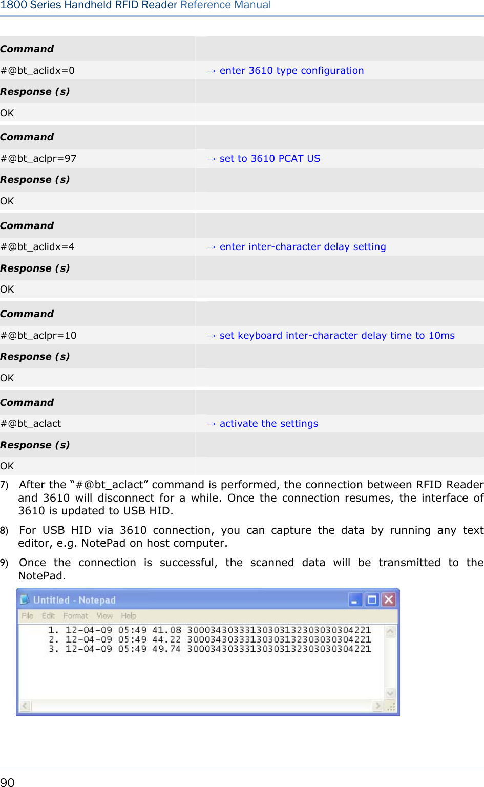
![63 Chapter 2 Communication Interface Command: #@bt_aclidx?\r Purpose Get Bluetooth® 3610 Parameter Index Response OK,[m]\r [m]: Parameter Index [m] Description Valid Parameters ‘0’ 3610 Type ‘096’ ~ ‘110’ ‘3’ Inter-function Delay ‘0’ ~ ‘254’ ‘4’ Inter-character Delay ‘0’ ~ ‘254’ ‘5’ Caps Lock State ‘0’ – OFF ‘1’ – ON ‘2’ – Auto ‘7’ Alphabets Transmission ‘0’ – Case Sensitive ‘1’ – Ignore Case ‘8’ Digits Transmission ‘0’ – Alpha Numeric Keypad ‘1’– Numeric Keypad ‘9’ Digits Position ‘0’ – Normal ‘1’– Lower Row ‘2’– Upper Row ‘10’ Keyboard Layout ‘0’ – Normal ‘1’ – AZERTY ‘2’ – QWERTZ ‘12’ HID Character Transmit Mode ‘0’– Batch Processing ‘1’– By Character ERR,[code] #@bt_aclidx=[m]\r Purpose Set Bluetooth® 3610 Parameter Index Response OK\r ERR,[code]\r #@bt_aclpr?\r Purpose Get Bluetooth® 3610 Parameter Value Response OK,[m]\r [m]: Parameter ERR,[code]\r](https://usermanual.wiki/CipherLab/1862/User-Guide-2462059-Page-75.png)
![64 1800 Series Handheld RFID Reader Reference Manual #@bt_aclpr=[m]\r Purpose Set Bluetooth® 3610 Parameter Value Response OK\r ERR,[code]\r #@bt_aclact\r Purpose Activate Bluetooth® 3610 Setting Request #@bt_aclact\r [m]: Parameter Response OK\r ERR,[code]\r](https://usermanual.wiki/CipherLab/1862/User-Guide-2462059-Page-76.png)


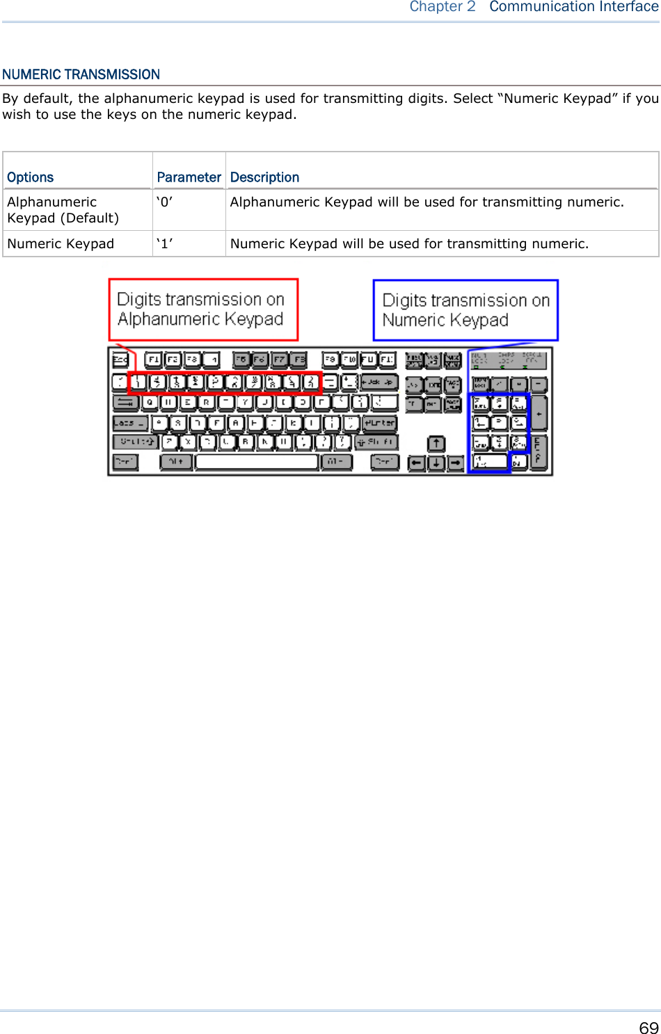
![67 Chapter 2 Communication Interface NUMERIC LAYOUT Select a proper layout that matches the alphabets layout. RFID Reader will make adjustments according to this setting. Options Parameter Description Normal (Default) ‘0’ Depends on the [Shift] key or [Shift Lock] setting Lower Row ‘1’ For QWERTY or QWERTZ keyboard Upper Row ‘2’ For AZERTY keyboard Note: This setting is to be used with the Character Substitution setting when support to certain keyboard types (languages) is unavailable but required. CAPITAL LOCK SETTING In order to send the alphabets with correct case, RFID Reader needs to know the status of Caps Lock on the keyboard. Incorrect settings may result in reversed case of the alphabets being transmitted. Status Options Parameter Description Capital Lock OFF (Default) ‘0’ Assuming that the status of Caps Lock on the keyboard is OFF, transmitted characters are exactly the same as in the tag (when "case-sensitive" is selected for Alphabets Transmission). Capital Lock ON ‘1’ Assuming that the status of Caps Lock on the keyboard is ON, transmitted characters are exactly the same as in the tag (when "case-sensitive" is selected for Alphabets Transmission). Refer to the Capital Lock Type above. Auto Detection ‘2’ RFID Reader will automatically detect the status of Caps Lock on the keyboard before data is transmitted; transmitted characters are exactly the same as in the tag (when "case-sensitive" is selected for Alphabets Transmission).](https://usermanual.wiki/CipherLab/1862/User-Guide-2462059-Page-79.png)
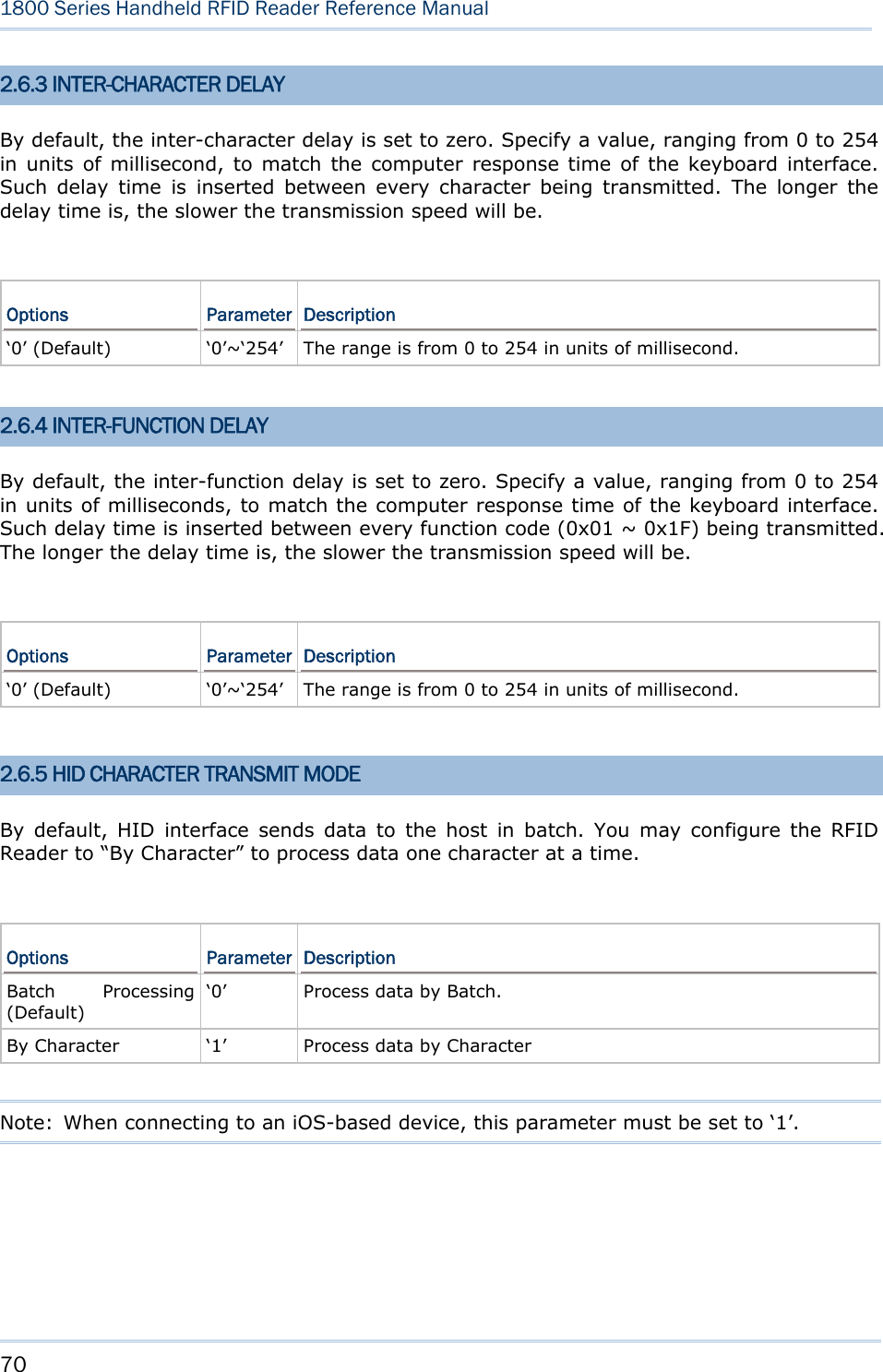
![68 1800 Series Handheld RFID Reader Reference Manual ALPHABETS TRANSMISSION By default, the alphabets transmission is case-sensitive, meaning that the alphabets will be transmitted according to their original case, the status of Caps Lock on the keyboard, as well as the Capital Lock setting. Select [Ignore Case] to have alphabets transmitted according to the status of Caps Lock on the keyboard only. Options Parameter Description Case Sensitive (Default) ‘0’ Alphabets will be transmitted according to the original case. Ignore Case ‘1’ Alphabets will be transmitted according to the status of Caps Lock on the keyboard only.](https://usermanual.wiki/CipherLab/1862/User-Guide-2462059-Page-80.png)
![73 Chapter 3 Setting Up a WPAN Connection 3.1.2 CONFIGURE RELATED SETTINGS Bluetooth Discoverable RFID Reader can be configured to hide itself from other devices equipped with Bluetooth® wireless technology. Simply disable the device name broadcasting setting so that it won’t be discovered by any other computers. Command: #@bt_visible?\r Purpose Get Bluetooth® Discoverable Status Response OK,[m]\r (Default m= ‘1’) [m]: Discoverable ‘0’ – Disable ‘1’ – Enable ERR,[code]\r #@bt_visible=[m]\r Purpose Set Bluetooth® Discoverable Property Response OK\r ERR,[code]\r Note: By default, device name broadcasting is enabled (which is required for initial connection). BT POWER SAVING By default, this feature is enabled, meaning the RFID Reader will listen to the wireless network at a reduced rate. Command: #@bt_ps?\r Purpose Get Bluetooth® Power Saving Response OK,[m]\r (Default m= ‘1’) [m]: Power Saving ‘0’ – Disable ‘1’ – Enable ERR,[code]\r #@bt_ps=[m]\r Purpose Set Bluetooth® Power Saving Response OK\r](https://usermanual.wiki/CipherLab/1862/User-Guide-2462059-Page-85.png)
![74 1800 Series Handheld RFID Reader Reference Manual ERR,[code]\r Note: When connecting more than two devices to a notebook computer with Bluetooth® wireless technology, we suggest that you disable the Bluetooth® Power Saving function for a more reliable connection. AUTHENTICATION When the authentication and PIN code are changed on the RFID Reader, you have to remove the RFID Reader from the paired device list (called unpairing) and go through the whole process to re-establish the connection. Command: #@bt_secure?\r Purpose Get Bluetooth® Authentication Response OK,[m]\r (Default m= ‘0’) [m]: Authentication ‘0’ – Disable ‘1’ – Enable ERR,[code]\r #@bt_secure=[m]\r Purpose Set Bluetooth® Authentication Response OK\r ERR,[code]\r With 1800 authentication disabled, the 1800 reader can pair with multiple Bluetooth® devices. Successful pairing records will be kept for future re-connection without authentication process. With 1800 authentication enabled, the reader can keep only one pairing record. If the reader pairs with device A and then pairs with device B, the pairing record of device B will be kept. If device A wants to connect to the reader, the pairing process must be made again. If the pairing record on a paired device is cleared, the paired device won’t be able again to pair with the reader whose authentication is enabled; to solve this problem, users are supposed to manually clear the pairing record on the reader by issuing “#@BT_RESET” command or using the function key combination. PIN CODE RFID Reader allows up to 16 characters for a PIN code. If the PIN or passkey is incorrect, any connection requirement will be rejected by RFID Reader. See step 8 in 3.1.3 Bluetooth® HID and SPP Slave. By default, the PIN code value is “0000”. Command: #@bt_pin?\r](https://usermanual.wiki/CipherLab/1862/User-Guide-2462059-Page-86.png)
![75 Chapter 3 Setting Up a WPAN Connection Purpose Get Bluetooth® PIN Code Response OK,[m],[n]\r (Default m= ‘0000’, n= ‘4’) [m]: length of PIN ‘0’ ~ ‘16’, ‘0’ means no PIN [n]: PIN, 1~16 characters, only exists when [m]!= ‘0’ (m≠0) ERR,[code]\r #@bt_pin=[m],[n]\r Purpose Set Bluetooth® PIN Code Response OK\r ERR,[code]\r Note: When using Bluetooth® HID, some device driver may not support pre-defined PIN code for authentication. In this case, make sure you have the RFID Reader set to “No PIN required” or “User-specified PIN” before pairing. While pairing, the host PIN code will be displayed on the host computer. Have the RFID Reader to input the matching PIN code for connection. Refer to 1.3.2 Bluetooth® Pairing Mode. User-specified PIN No PIN required](https://usermanual.wiki/CipherLab/1862/User-Guide-2462059-Page-87.png)
![76 1800 Series Handheld RFID Reader Reference Manual SSP (Secure Simple Pairing ) Command: #@bt_ssp?\r Purpose Get Bluetooth® SSP Status Response OK,[m]\r [m]:SSP Mode ‘0’ – Disable ‘1’ – Enable (Default) ERR, [code]\r #@bt_ssp=[m]\r Purpose Enable/Disable Bluetooth® SSP Response OK\r ERR,[code]\r Note: SSP feature is available only for iOS-based devices currently. We suggest it is better to enable SSP function when using an iOS-based device.](https://usermanual.wiki/CipherLab/1862/User-Guide-2462059-Page-88.png)
![77 Chapter 3 Setting Up a WPAN Connection 3.1.3 BLUETOOTH® HID AND SPP SLAVE The procedure goes through associating devices for establishing a WPAN connection, which is pretty much the same except for the software you are using. If your computer is running Microsoft® Windows® XP (SP1 to SP3), Windows Vista® Service Pack 1 (SP1) and Windows 7, you can use the software support that Windows® includes, or you can use the driver that the device manufacturer provides. Now, let’s try using the software support that Windows® XP Service Pack 2 includes. BLUETOOTH® HID By default, the keyboard type of Bluetooth® HID is set to PCAT (US). When Bluetooth® HID is re-activated, you have to select a keyboard type to complete this setting. Refer to 2.5.1 Activate Bluetooth® HID & Select Keyboard Type. Refer to steps 1~11 below for a Bluetooth® connection. BLUETOOTH® SPP SLAVE 1) Enable the Bluetooth® function on host computer. (Windows® XP only) 2) Double-click the Bluetooth® icon located on the lower right of the taskbar. Alternatively, you may go to Control Panel > Bluetooth Devices. 3) Click [Add] to search devices nearby.](https://usermanual.wiki/CipherLab/1862/User-Guide-2462059-Page-89.png)
![78 1800 Series Handheld RFID Reader Reference Manual 4) Turn on RFID Reader with correct WPAN settings, such as select Bluetooth® SPP Slave or HID, broadcasting enabled, authentication enabled, and PIN code specified, etc if you want to use a passkey. Select “My device is set up and ready to be found” check box on the “Add Bluetooth® Device Wizard” window. 5) Click [Next]. 6) Wait for a few seconds for the Wizard to search available devices nearby. All available devices will appear on the search window. Select the device (e.g. RFID Reader) that you want to connect. If the target device does not appear on the list, click [Search Again] to refresh the list. The RFID Reader might enter power-saving mode during an idling time (=discoverable), and you can press the <Trigger> to have it active again. It will then stay active for a specified period of time (2 minutes by default) and wait for the host computer to establish a connection.](https://usermanual.wiki/CipherLab/1862/User-Guide-2462059-Page-90.png)
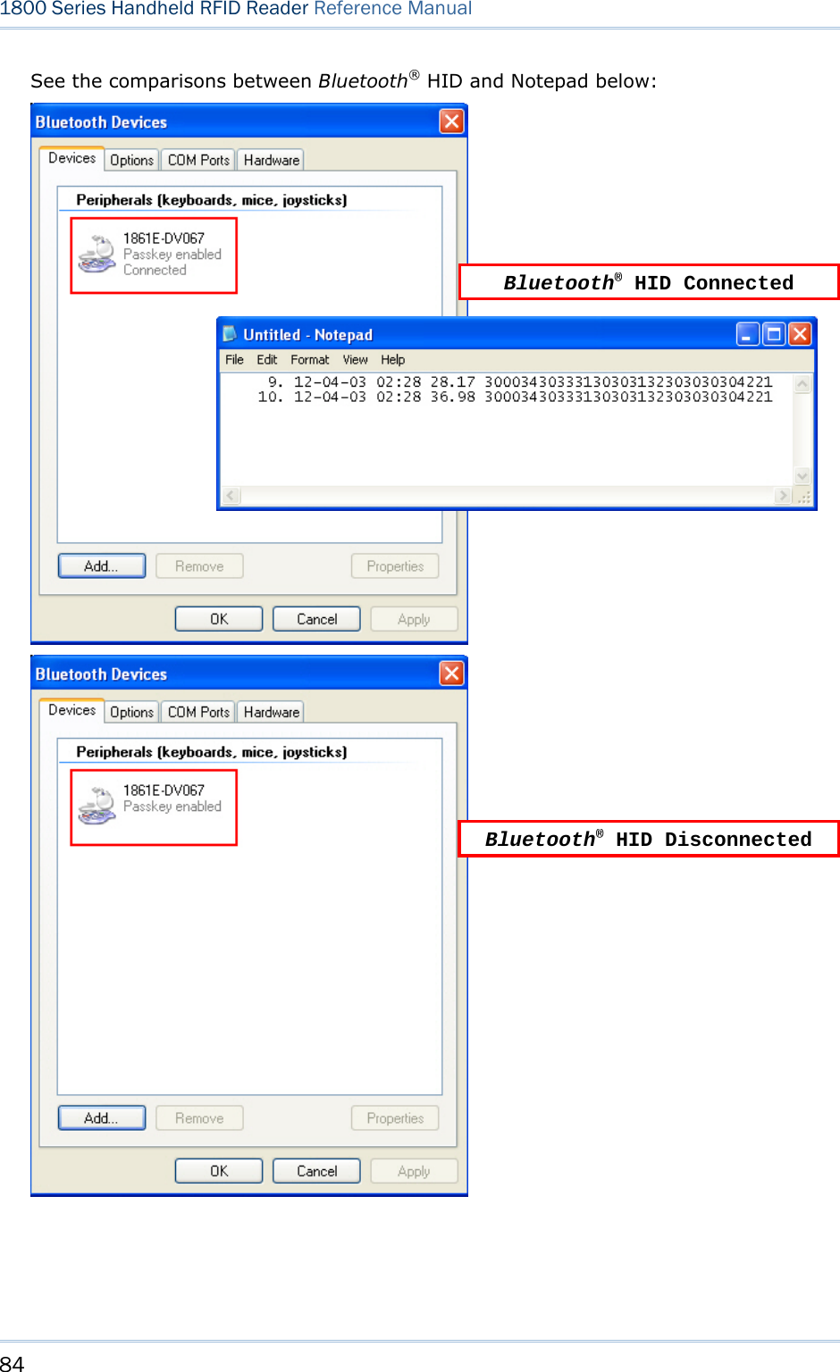
![79 Chapter 3 Setting Up a WPAN Connection 7) See SPP Slave connection below, click [Next]. See BT HID connection below, click [Next].](https://usermanual.wiki/CipherLab/1862/User-Guide-2462059-Page-91.png)
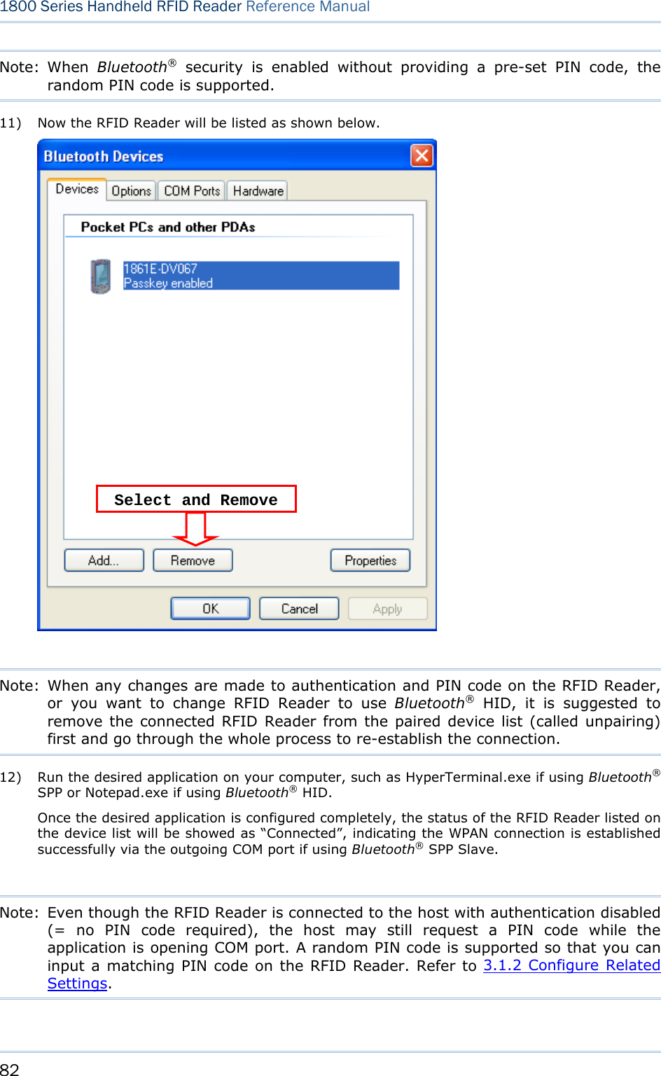
![80 1800 Series Handheld RFID Reader Reference Manual 8) Enter the passkey for authentication, which must be exactly the same as configured for RFID Reader. Click [Next]. 9) Wait for a few seconds for Windows to confirm the Passkey.](https://usermanual.wiki/CipherLab/1862/User-Guide-2462059-Page-92.png)
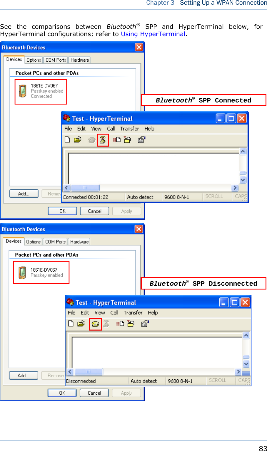
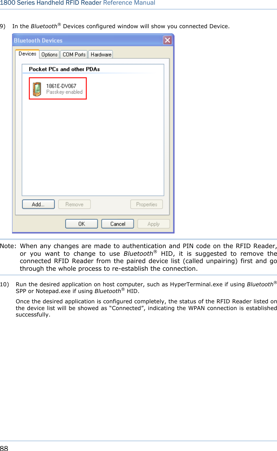
![81 Chapter 3 Setting Up a WPAN Connection 10) See SPP Slave connection below, click [Finish]. See BT HID connection below, click [Finish]. RFID Reader as Bluetooth® SPP Slave](https://usermanual.wiki/CipherLab/1862/User-Guide-2462059-Page-93.png)
![85 Chapter 3 Setting Up a WPAN Connection 3.1.4 BLUETOOTH® SPP MASTER BLUETOOTH® SPP MASTER 1) Enable the Bluetooth® function on the host computer. 2) Double-click the Bluetooth® icon located on the lower right of the taskbar. Alternatively, you may go to Control Panel > Bluetooth Devices. 3) Select Hardware tab and click [Properties].](https://usermanual.wiki/CipherLab/1862/User-Guide-2462059-Page-97.png)
![87 Chapter 3 Setting Up a WPAN Connection 7) In the Add Bluetooth® Device Wizard window, key in the passkey that is the same as you have entered on the RFID Reader. The default value is 0000. Click [Next]. 8) Click [Finish].](https://usermanual.wiki/CipherLab/1862/User-Guide-2462059-Page-99.png)
![92 1800 Series Handheld RFID Reader Reference Manual 3.3 DISCONNECTION You can follow the methods below to break a connection between RFID Reader and host computer: 1) Issue #@bt_disc” to disconnect from current connected device. 2) Issue “#@bt_type” to change the connection type. Current connection will be broken. 3) Issue “#@bt_reset” to clear the information of remote device. Current connection will be broken and connection type will resume to SPP slave. 4) Use Function key to break the connection, refer to 1.4.2 Function Key . 3.3.1 BREAK A CONNECTION You can force the RFID Reader to break a Bluetooth® connection with host computer by issuing command. Command: #@bt_disc\r Purpose Break Current Bluetooth® Connection Response OK\r ERR,[code]\r Note: The issues below will also result in disconnection: 1) Entering power saving mode, refer to 1.1.3 Power Saving Mode. 2) System power off automatically, refer to 1.1.2 Power OFF. 3) Disconnection requirement from the connected device. 3.3.2 RESET A CONNECTION Perform the “#@bt_reset” command to clear the current pairing record and restore the connection type to default SPP Slave. Then go through the whole process in Setting Up a WPAN Connection to establish a new connection. Command: #@bt_reset\r Purpose Reset Bluetooth® Connection Response OK\r ERR,[code]\r](https://usermanual.wiki/CipherLab/1862/User-Guide-2462059-Page-104.png)
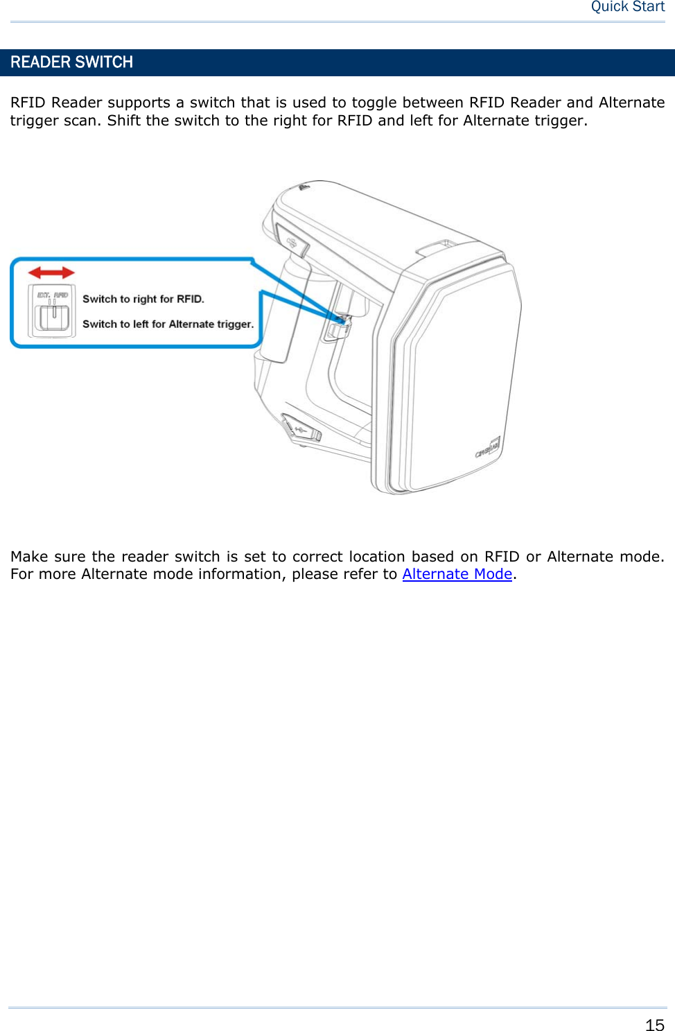
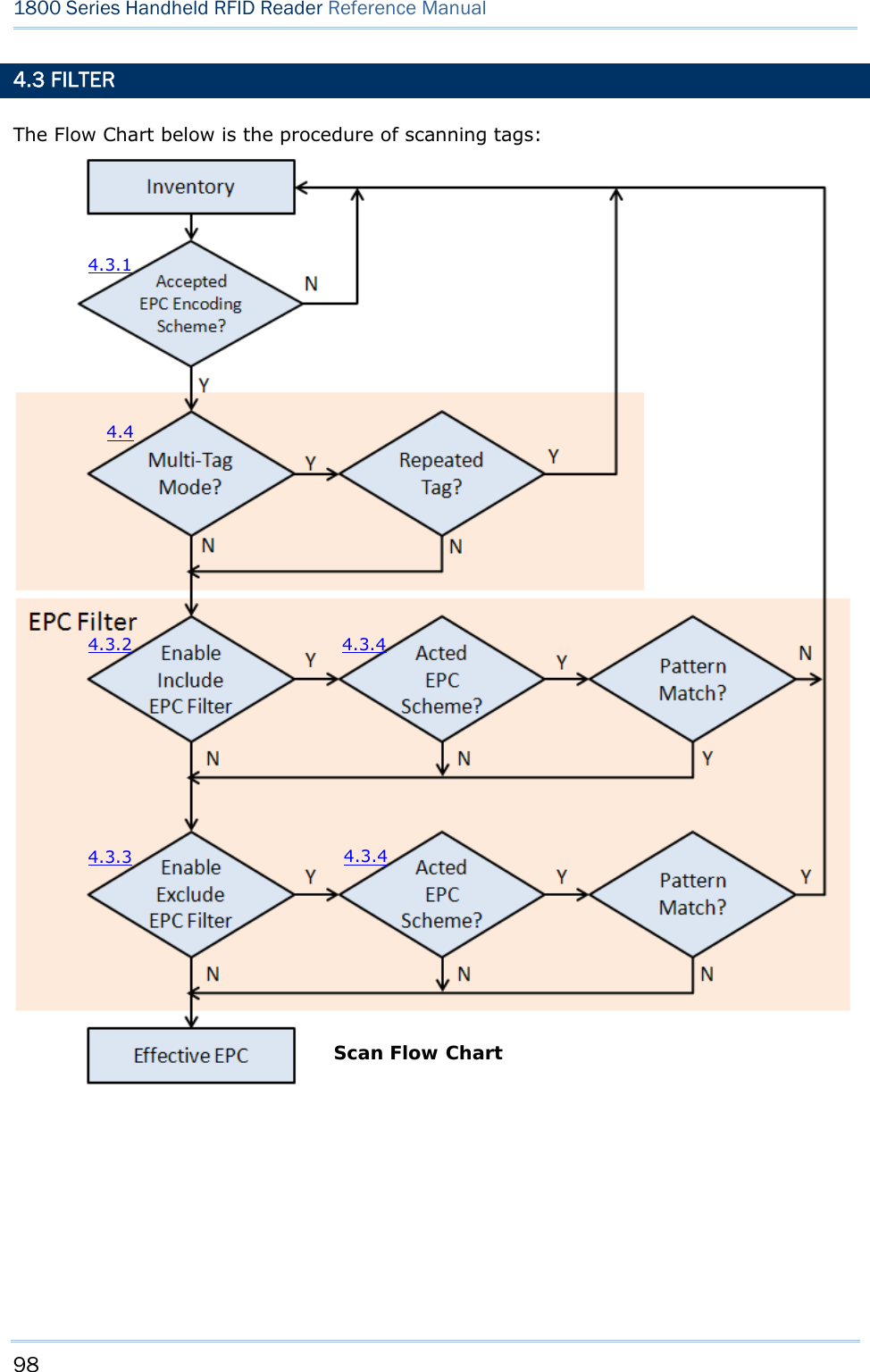
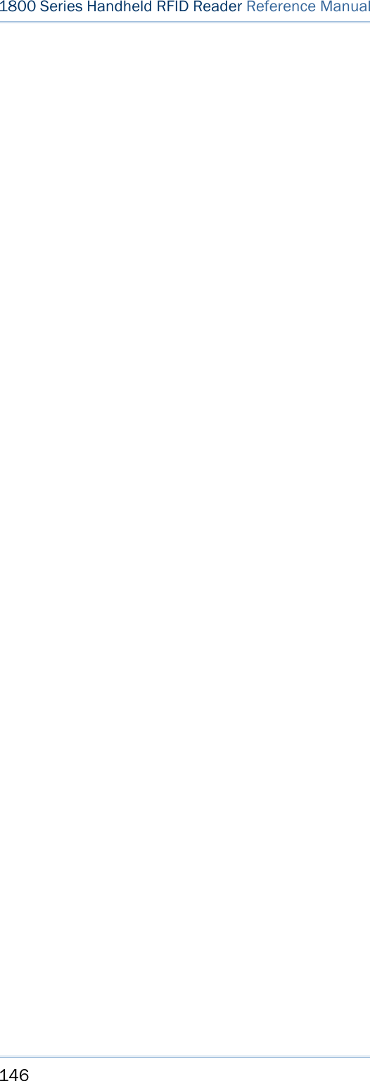
![93 Equipped with a switch in the handle, the RFID Reader allows you to toggle between RFID and Alternate modes. Make sure the switch is well-positioned before taking on RFID scanning tasks. You can also get the status between RFID and Alternate modes by issuing the “#@rf_switch?” command. Command: #@rf_switch?\r Purpose Get the Status between RFID and Alternate Mode Response OK,[m]\r (Default m= ‘1’) [m]: Status of RFID/EXT Switch ‘0’ – EXT Mode (Alternate Mode) ‘1’ – RFID Mode ERR,[code]\r IN THIS CHAPTER 4.1 Scan Mode................................................................ 94 4.2 Scan Time ................................................................ 96 4.3 Filter........................................................................ 98 4.4 Multi-Tag.................................................................110 4.5 Access Tag .............................................................114 4.6 Advanced Settings ....................................................121 Chapter 4 SCANNING UHF RFID TAG](https://usermanual.wiki/CipherLab/1862/User-Guide-2462059-Page-105.png)
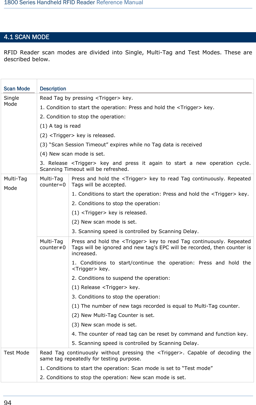
![95 Chapter 4 SCANNING UHF RFID Tag 3. Scan Session Timeout, Scanning Delay, Multi-Tag Counter and EPC filter parameters have no effect in this mode. 4. If RFID Function=Write Tag Memory, the RFID Reader can not be set to Test Mode. Command: #@rf_scan?\r Purpose Get Scan Mode Response OK,[m]\r (Default m= ‘6’) [m]: Scan Mode ‘6’ – Single Mode ‘7’ – Test Mode ‘9’ – Multi – Tag Mode, refer to 4.4 Multi-Tag. ERR,[code]\r #@rf_scan=[m]\r Purpose Set Scan Mode Response OK\r ERR,[code]\r](https://usermanual.wiki/CipherLab/1862/User-Guide-2462059-Page-107.png)
![96 1800 Series Handheld RFID Reader Reference Manual 4.2 SCAN TIME 4.2.1 TIMEOUT You have to specify the scanning timeout interval (0~254 sec.; 0= Disable) when the scan mode is set to Single Mode. Operation will stop if the operation time = Scan Session Timeout and No Tag data is received. The range of timeout is 0~254 second. By default the value is set to ‘0’ to disable scanning timeout. Command: #@rf_tscan?\r Purpose Get Scan Session Timeout Response OK,[m]\r (Default m= ‘0’) [m]: Timeout, ‘0’ ~ ‘254’ ERR,[code]\r #@rf_tscan=[m]\r Purpose Set Scan Section Timeout Response OK\r ERR,[code]\r Note: This command is available for Single Mode. For example, if you set the “#@rf_tscan” value to 5, the waiting time is set to 5 sec. upon pressing the trigger. If no tag is scanned within that period, the operation will stop.](https://usermanual.wiki/CipherLab/1862/User-Guide-2462059-Page-108.png)
![97 Chapter 4 SCANNING UHF RFID Tag 4.2.2 DELAY TIME You can specify the scanning delay time when the scan mode is set to Multi-Tag Mode. Command: #@rf_scandly?\r Purpose Get Scan Delay Response OK,[m]\r (Default m= ‘0’) [m]: Scan Delay ‘0’ 100ms ‘1’ 200ms ‘2’ 400ms ‘3’ 800ms ‘4’ 1 sec ‘5’ 2 sec ‘6’ 3 sec ‘7’ 5 sec ERR,[code]\r #@rf_scandly=[m]\r Purpose Set Scan Delay Response OK\r ERR,[code]\r](https://usermanual.wiki/CipherLab/1862/User-Guide-2462059-Page-109.png)
![99 Chapter 4 SCANNING UHF RFID Tag 4.3.1 EPC ENCODING SCHEME This function will decide which kind of tags can be read. Accepted EPC Encoding Scheme – Group 1 Command: #@rf_epctype1?\r Purpose Get EPC Scheme – Group1 Response OK,[m]\r (Default = ‘11111111’ ) [m]: EPC Scheme – Group1 8 character series composed of "0" and "1" to enable or disable the listed tag types. ‘0’ – disable the tag type. ‘1’ – enable the tag type. Character Tag Type 1 (Left) GDTI96 2 GSRN96 3 DoD96S 4 SGTIN96 5 SSCC96 6 GLN96 7 GRAI96 8(Right) GIAI96 e.g. [m]=“10011000” means only to enable GDTI96, SGTIN96,SSCC96 ERR,[code]\r #@rf_epctype1=[m]\r Purpose Set EPC Scheme – Group1 Response OK\r ERR,[code]\r Accepted EPC Encoding Scheme – Group 2 Command: #@rf_epctype2?\r Purpose Get EPC Scheme – Group2 Response OK,[m]\r (Default = ‘11111111’ ) [m]: EPC Scheme – Group2 8 character series composed of "0" and "1" to enable or disable the listed tag types.](https://usermanual.wiki/CipherLab/1862/User-Guide-2462059-Page-111.png)
![100 1800 Series Handheld RFID Reader Reference Manual 0 Æ disable the tag type. 1 Æ enable the tag type. Character Tag Type 1 (Left) GID96 2 SGTIN198 3 GRAI170 4 GIAI202 5 SGLN195 6 GDTI113 7 ADI 8(Right) Reserved Always read and write as 1 ERR,[code]\r #@rf_epctype2=[m]\r Purpose Set EPC Scheme – Group2 Response OK\r ERR,[code]\r Note: If both EPC Scheme Group 1 and 2 are set to “11111111”, it means with accepting all tags.](https://usermanual.wiki/CipherLab/1862/User-Guide-2462059-Page-112.png)
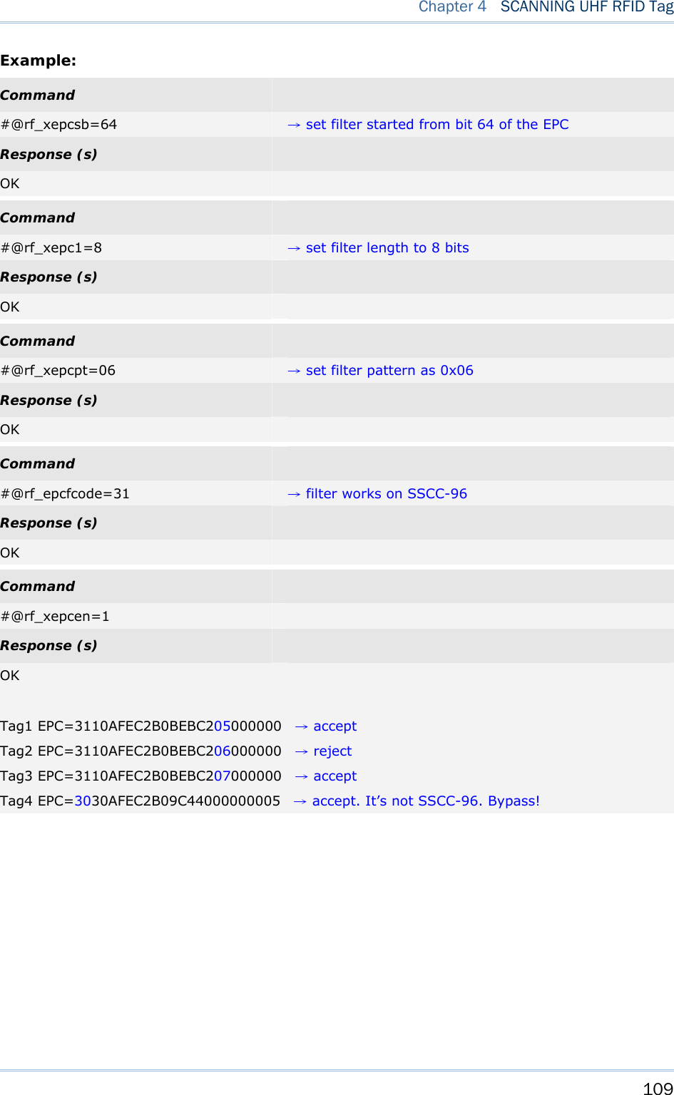
![101 Chapter 4 SCANNING UHF RFID Tag 4.3.2 AFFECTED TAG OF INCLUDED/EXCLUDED EPC FILTER Note: The EPC encoding scheme described in Section 4.3.1 allows RFID reader to accept various types of tag. However, the EPC filter can pick only one type of tag from those EPC tags; other types will be bypassed. Command: #@rf_epcfcode?\r Purpose Get Tag type that EPC filter works on Response OK,[m]\r (Default=’30’) [m]: Acted Scheme for EPC Filter* Tag encoding type [m] EPC Encoding Scheme ‘2C’ GDTI-96 ‘2D’ GSRN-96 ‘2F’ USDoD-96 ‘30’ SGTIN-96(Default) ‘31’ SSCC-96 ‘32’ SGLN-96 ‘33’ GRAI-96 ‘34’ GIAI-96 ‘35’ GID-96 ‘36’ SGTIN-198 ‘37’ GRAI-170 ‘38’ GIAI-202 ‘39’ SGLN-195 ‘3A’ GDTI-113 ‘3B’ ADI ERR,[code]\r #@rf_epcfcode=[m]\r Purpose Set Tag type that EPC filter is applied to Response OK\r ERR,[code]\r](https://usermanual.wiki/CipherLab/1862/User-Guide-2462059-Page-113.png)
![102 1800 Series Handheld RFID Reader Reference Manual 4.3.3 INCLUDED EPC EPC filter is designed to check the contents of the EPC tag with the specified tag type to determine whether the scanned record is accepted or ignored. Besides configuring the tag type (refer to Section 4.3.2) to be filtered, users are supposed to specify start bits, length bits, and EPC pattern when using the EPC filter. Start Bits Define the start bit of EPC that you want to filter. Command: #@rf_sepcsb?\r Purpose Get Included EPC Start bit Response OK,[m]\r (Default m= ‘0’) [m]: Start bit of EPC. Max. 255 and sum of start bit and pattern length bit cannot be more than 256. ERR,[code]\r #@rf_sepcsb=[m]\r Purpose Set Included EPC Start bit Response OK\r ERR,[code]\r Length Bits The Max. value is 256. Sum of star bit and pattern length bit can not be more than 256. A value from 0 to 256 can be specified. EPC filter is disabled when the length is set to ‘0’. Command: #@rf_sepcl?\r Purpose Get Included EPC Length Response OK,[m]\r (Default m= ‘0’) [m]: Pattern length bits. Max 256 and sum of start bit and pattern length bit cannot be more than 256. ERR,[code]\r #@rf_sepcl=[m]\r Purpose Set Included EPC Length Response OK\r ERR,[code]\r](https://usermanual.wiki/CipherLab/1862/User-Guide-2462059-Page-114.png)
![103 Chapter 4 SCANNING UHF RFID Tag EPC Pattern Define the hexadecimal pattern that is used to be compared. Command: #@rf_sepcpt?\r Purpose Get Included EPC Pattern Response OK,[m]\r (Default m= ‘00’) [m]: EPC pattern in hexadecimal value. ERR,[code]\r #@rf_sepcpt=[m]\r Purpose Set Included EPC Pattern Response OK\r ERR,[code]\r #@rf_sepcpt2?\r Purpose Get Included EPC2 Pattern Response OK,[m]\r (Default m= ‘00’) [m]: EPC pattern in hexadecimal value. ERR,[code]\r #@rf_sepcpt2=[m]\r Purpose Set Included EPC2 Pattern Response OK\r ERR,[code]\r State Disable or Enable Included EPC Filter function. When the value is set to ‘1’, Tag EPC will be accepted upon fitting the required pattern. If the value is set to ‘2’, Tag EPC will be accepted between pattern and pattern2. (Pattern<=Tag EPC<=Pattern2). Command: #@rf_sepcen?\r Purpose Get Included EPC State Response OK,[m]\r (Default m= ‘0’) [m]: ‘0’ – disable, ‘1’ – enable, ‘2’ – enable range filter ERR,[code]\r](https://usermanual.wiki/CipherLab/1862/User-Guide-2462059-Page-115.png)
![104 1800 Series Handheld RFID Reader Reference Manual #@rf_sepcen=[m]\r Purpose Set Included EPC State Response OK\r ERR,[code]\r Note: The pattern must be consistent with length so that you can filter the transmitted data and accept it.](https://usermanual.wiki/CipherLab/1862/User-Guide-2462059-Page-116.png)

![106 1800 Series Handheld RFID Reader Reference Manual 4.3.4 EXCLUDED EPC The following commands are used to "exclude" tags matching the criteria set by the filter. Start Define the start bit of EPC that you want to filter. Command: #@rf_xepcsb?\r Purpose Get Excluded EPC Start bit Response OK,[m]\r (Default m= ‘0’) [m]: Start bit of EPC. Max 255 and sum of start bit and pattern length bit cannot be more than 256. ERR,[code]\r #@rf_xepcsb=[m]\r Purpose Set Excluded EPC Start bit Response OK\r ERR,[code]\r Length The Max. value is 256. Sum of star bit and pattern length bit can not be more than 256. A value from 0 to 256 can be specified. EPC filter is useless when the length is set to ‘0’. Command: #@rf_xepcl?\r Purpose Get Excluded EPC Length Response OK,[m]\r (Default m= ‘0’) [m]: Pattern length bits. Max 256 and sum of start bit and pattern length bit cannot be more than 256. ERR,[code]\r #@rf_xepcl=[m]\r Purpose Set Excluded EPC Length Response OK\r ERR,[code]\r](https://usermanual.wiki/CipherLab/1862/User-Guide-2462059-Page-118.png)
![107 Chapter 4 SCANNING UHF RFID Tag EPC Pattern Define the hexadecimal pattern that is used to be compared. Command: #@rf_xepcpt?\r Purpose Get Excluded EPC Pattern Response OK,[m]\r (Default m= ‘00’) [m]: EPC pattern in hexadecimal value ERR,[code]\r #@rf_xepcpt=[m]\r Purpose Set Excluded EPC Pattern Response OK\r ERR,[code]\r #@rf_xepcpt2?\r Purpose Get Excluded EPC2 Pattern Response OK,[m]\r (Default m= ‘00’) [m]: EPC pattern in hexadecimal value. ERR,[code]\r #@rf_xepcpt2=[m]\r Purpose Set Excluded EPC2 Pattern Response OK\r ERR,[code]\r State Disable or Enable Excluded EPC Filter function. When the value is set to ‘1’, Tag EPC will be eliminated upon matching the required pattern. If the value is set to ‘2’, Tag EPC will be eliminated between pattern and pattern2. (Pattern<=Tag EPC<=Pattern2). Command: #@rf_xepcen?\r Purpose Get Excluded EPC State Response OK,[m]\r (Default m= ‘0’) [m]: ‘0’ – disable, ‘1’ – enable, ‘2’ – enable range filter ERR,[code]\r](https://usermanual.wiki/CipherLab/1862/User-Guide-2462059-Page-119.png)
![108 1800 Series Handheld RFID Reader Reference Manual #@rf_xepcen=[m]\r Purpose Set Excluded EPC State Response OK\r ERR,[code]\r Note: The pattern must be consistent with length so that you can filter the transmitted data.](https://usermanual.wiki/CipherLab/1862/User-Guide-2462059-Page-120.png)
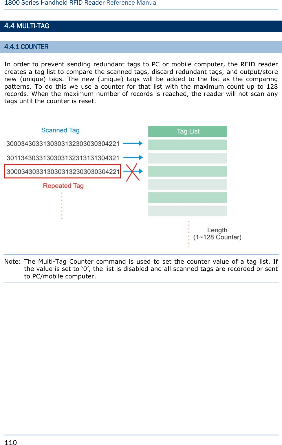
![111 Chapter 4 SCANNING UHF RFID Tag Counter Command: #@rf_mtagcnt?\r Purpose Get Multi-Tag Counter Value Response OK,[m]\r (Default m= ‘128’) [m]: Multi-Tag Counter value: ‘0’ (disable the counter), ‘1’ ~‘128’ ERR,[code]\r #@rf_mtagcnt=[m]\r Purpose Set Multi-Tag Counter Request #@rf_mtagcnt=[m]\r [m]: Multi-Tag Counter Response OK\r ERR,[code]\r Multi-Tag List Type Command: #@rf_mtaglist?\r Purpose Get Multi-Tag List Type Response OK,[m]\r (Default m= ‘0’) [m]: Multi-Tag List Type ‘0’ – EPC ‘1’ TID ERR,[code]\r #@rf_mtaglist=[m]\r Purpose Set Multi-Tag List Type Response OK\r ERR,[code]\r](https://usermanual.wiki/CipherLab/1862/User-Guide-2462059-Page-123.png)
![112 1800 Series Handheld RFID Reader Reference Manual 4.4.2 COUNTER RELOAD When the tag list is full, please issue "#@rf_mtagcnt=[m]\r" command again to reset the counter. Once reset, the tag list is cleared and scanning tasks can be continued.](https://usermanual.wiki/CipherLab/1862/User-Guide-2462059-Page-124.png)
![113 Chapter 4 SCANNING UHF RFID Tag 4.4.3 MULTI-TAG BEEP In order to differentiate between tags read, the reader will beep in the following sequence: Get a new tag: one short beep with high tone denoting that a tag is scanned successfully. Please refer to 1.5 Beeper. Get a repeated tag: one short beep with low tone (disabled by default) Full Tag List: six short beeps, low-mid-high-low-mid-high (enabled by default) Beeping Status Enabling the beeper for multi-tag beeping can be set using the following commands. Command: #@rf_mtagbeep?\r Purpose Get Multi-Tag Beeping Response OK,[m],[n]\r (Default m= ‘0’, n= ‘1’) [m]: Repeated Tag Beeping [n]: Tag List Full Beeping ERR,[code]\r #@rf_mtagbeep=[m],[n]\r Purpose Set Multi-Tag Beeping Request #@rf_mtagbeep=[m],[n]\r [m]: Repeated Tag Beeping. ‘0’ – Disable, ‘1’ – Enable [n]: Tag List Full Beeping. ‘0’ – Disable, ‘1’ – Enable Response OK\r ERR,[code]\r](https://usermanual.wiki/CipherLab/1862/User-Guide-2462059-Page-125.png)
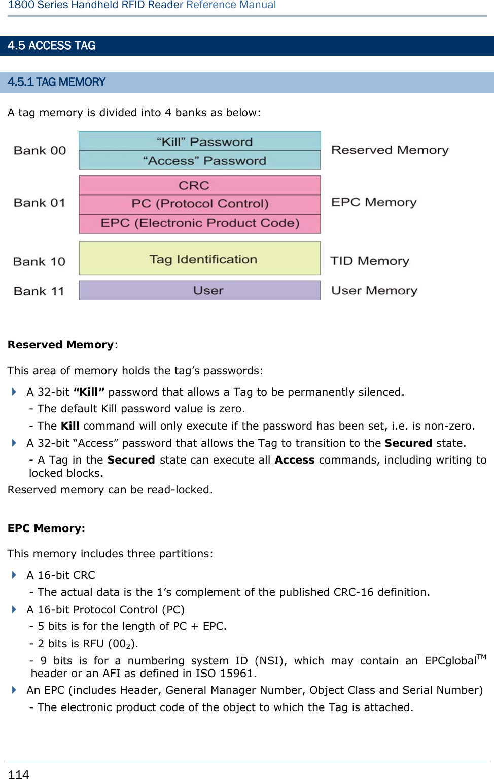
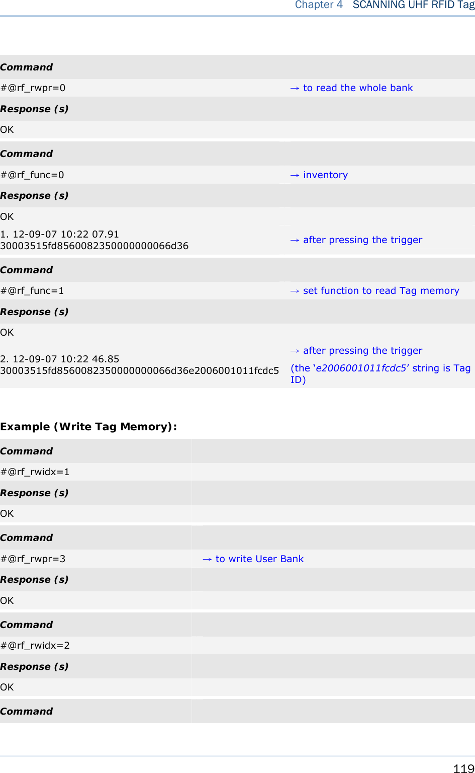
![116 1800 Series Handheld RFID Reader Reference Manual 4.5.2 READ/WRITE TAG By default, the RFID Reader access mode is set to Inventory to get EPC of a Tag. If you want to read all data stored in a Tag, you would issue the “#@rf_func=1” command that allows you to read Reserved, EPC, TID or User bank. RFID Function Command: #@rf_func?\r Purpose Get RFID Function Response OK,[m]\r (Default m= ‘0’) [m]: RFID Function ‘0’ – Inventory ‘1’ – Read Tag Memory ‘2’ – Write Tag Memory ERR,[code]\r #@rf_func=[m]\r Purpose Set RFID Function Response OK\r ERR,[code]\r Access Command: #@rf_rwidx?\r Purpose Get Index of Access Parameter Response OK,[m]\r [m]: Index of Access Parameter [m] Meaning Value ‘0’ Access Password ‘xxxxxxxx’ Access Password, 4 bytes, shown in Hexadecimal value. e.g. String ‘30313233’ indicates 0x30, 0x31, 0x32, 0x33. Default= ‘00000000’ ‘1’ Memory Bank ‘0’ – Reserved Bank](https://usermanual.wiki/CipherLab/1862/User-Guide-2462059-Page-128.png)
![117 Chapter 4 SCANNING UHF RFID Tag ‘1’ – EPC ‘2’ – TID ‘3’ – User Bank Default= ‘1’ ‘2’ Start Byte Only even numbers (‘0’, ‘2’, ‘4’ … ‘32’) are valid for the start byte. Default= ‘0’ ‘3’ Data Length Byte(s) Only even numbers (‘0’, ‘2’, ‘4’ … ‘32’) are valid for data length bytes. Default= ‘0’ ERR,[code] #@rf_rwidx=[m]\r Purpose Set Index of Access Parameter Response OK\r ERR,[code]\r #@rf_rwpr?\r Purpose Get Access Parameter Response OK,[m]\r [m]: Access Parameter ERR,[code]\r #@rf_rwpr=[m]\r Purpose Set Access Parameter Response OK\r ERR,[code]\r Write In addition to specifying parameters mentioned above, you are supposed to store data into RFID reader’s buffer before writing them into the tag memory. Command: #@rf_wbuf?\r Purpose Get Data in Reader Buffer Response OK,[m]\r (Default m= ‘0000’) [m]: Data stored in buffer shown in hexadecimal. e.g. ‘41’=>0x41= ‘A’ (2 bytes NULL)](https://usermanual.wiki/CipherLab/1862/User-Guide-2462059-Page-129.png)
![118 1800 Series Handheld RFID Reader Reference Manual ERR,[code]\r #@rf_wbuf=[m]\r Purpose Store Data into Reader Buffer Request #@rf_wbuf=[m]\r [m]: Data to be stored in buffer Buffer size = 32 bytes Input data shown in hexadecimal. The length of data must be an even number. To clear the buffer, [m]= ‘0000’ Response OK\r ERR,[code]\r Example (Read Tag Memory): Command #@rf_rwidx=1 Response (s) OK Command #@rf_rwpr=2 →to read TID Bank Response (s) OK Command #@rf_rwidx=2 Response (s) OK Command #@rf_rwpr=0 →start from byte 0 of TID Bank Response (s) OK Command #@rf_rwidx=3 Response (s) OK](https://usermanual.wiki/CipherLab/1862/User-Guide-2462059-Page-130.png)
![121 Chapter 4 SCANNING UHF RFID Tag 4.6 ADVANCED SETTINGS 4.6.1 APPLICATIONS IN MULTIPLE TAGS ENVIRONMENT In an energizing RF field, Tags implement a slot counter into which a random value involving the Q-parameter is loaded and Readers use the slot counter to regulate the probability of a Tag responding to commands of the Inventory operation. In practical applications, the ability of the Reader to read multiple Tags is affected by the Q value. Greater Q value allows the Reader to identify and collect information from more Tags; however, the reading distance will thus be decreased, and vice versa. The Q value should be set to zero in the case of a single Tag field. For the multiple Tags field, Q should be increased depending on the amount of Tags. A valid Q value can take any integer between 0 to 15. Command: #@rf_q?\r Purpose Get the Current Q Value Response OK,[m]\r [m]: Q value Valid integer value ranging from 0 to 15 (default=0 for 1861; default=4 for 1862) ERR,[code]\r #@rf_q=[m]\r Purpose Set New Q Value Request [m]: The number of slots (Q) for the inventory round. Response OK\r ERR,[code]\r](https://usermanual.wiki/CipherLab/1862/User-Guide-2462059-Page-133.png)
![122 1800 Series Handheld RFID Reader Reference Manual 4.6.2 ADJUSTMENT FOR OUTPUT POWER LEVEL OF THE READER Reading distance of the Reader varies according to its output power level. The output power level is set to the maximum value by default. Users can decrease the power level for reasons such as: Within the same frequency band, you may try to prevent RF interference for your own reason or to comply with the regulations. For near field applications, you want to write data into the nearest Tag ensuring that the data won’t be written into neighbouring ones. Command: #@rf_plv?\r Purpose Get the Current Output Power Level of the Reader Response OK,[m]\r [m]: Output power level For 1861, valid power level ranges from 0 to 3. Default value is set to 3. For 1862, valid power level ranges from 0 to 19. Default value is set to 15. ERR,[code]\r #@rf_plv=[m]\r Purpose Set New Output Power Level of the Reader Request [m]: Output power level Response OK\r ERR,[code]\r](https://usermanual.wiki/CipherLab/1862/User-Guide-2462059-Page-134.png)
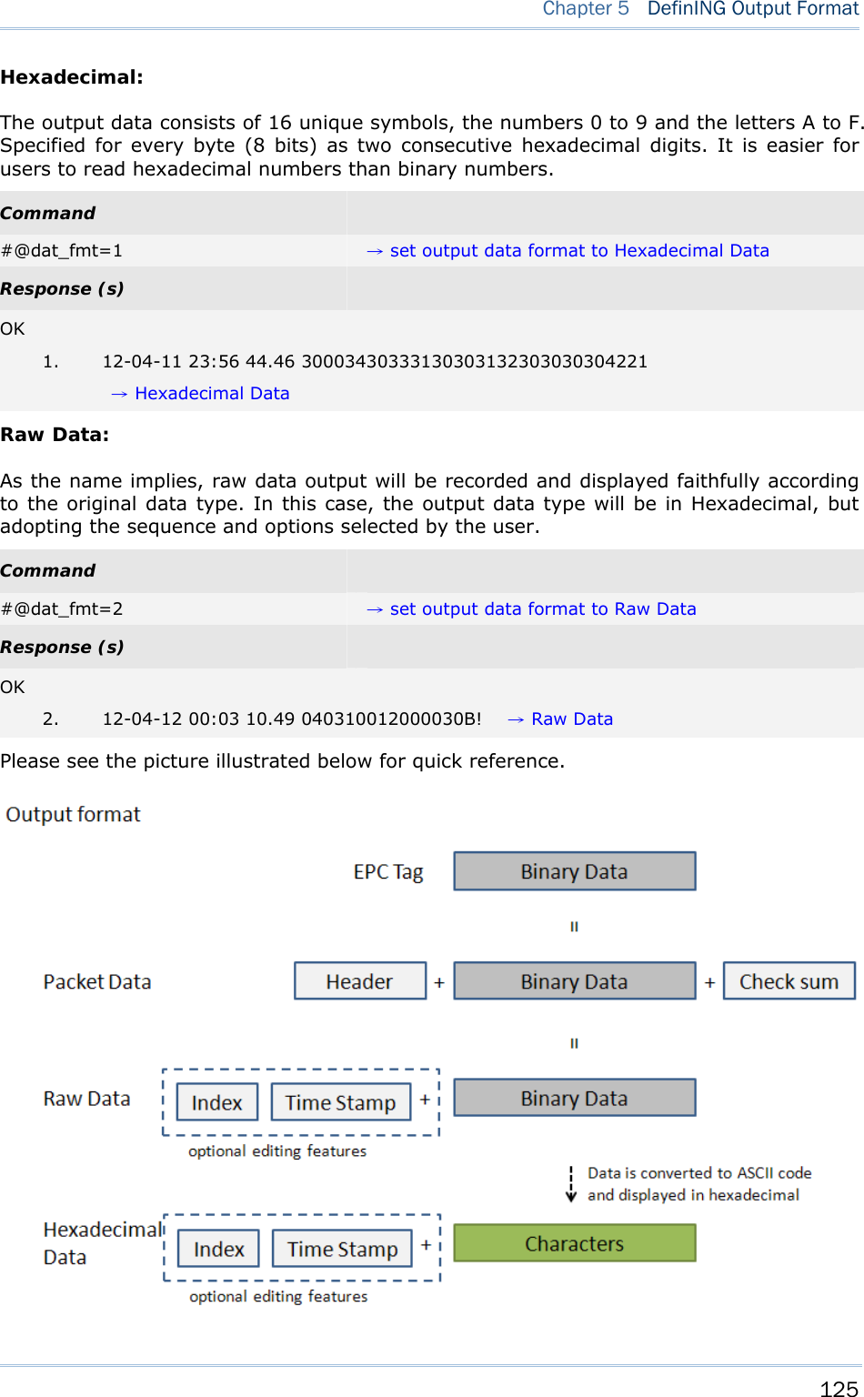
![124 1800 Series Handheld RFID Reader Reference Manual 5.1 OUTPUT FORMAT Before transmitting data captured by the reader you can edit, add and re-order the sequence of the final transmitted data. There are standard formats for the specified interfaces described below. BT SPP/USB VCOM via 3610 The output formats for Bluetooth® SPP/USB VCOM via 3610 can be one of Packet Data, Hexadecimal and Raw Data. The default value is Packet Data. BT HID/USB HID via 3610 The output formats for Bluetooth® HID/USB HID via 3610 can be one of Hexadecimal and Raw Data. The default value is Hexadecimal. Note: Bluetooth® HID or USB HID via 3610 interface does not support Packet Data as an output format. Command: #@dat_fmt?\r Purpose Get Current Output Data Format Response OK,[m]\r (Default m= ‘0’) [m]: Output Data Format [m] BT SPP / USB VCOM via 3610 BT HID / USB HID via 3610 ‘0’ Packet Data ‘1’ Hexadecimal Hexadecimal ‘2’ Raw Data Raw Data ERR,[code]\r #@dat_fmt=[m]\r Purpose Set New Output Data Format Response OK\r ERR,[code]\r Example: Packet Data: In order to enhance data reliability during transmission, header and checksum are added before transmitting. This is normally used for terminal application programming. Please note that Packet data does not allow any editing features.](https://usermanual.wiki/CipherLab/1862/User-Guide-2462059-Page-136.png)
![126 1800 Series Handheld RFID Reader Reference Manual 5.2 FORMAT EDITING FOR HEXADECIMAL AND RAW DATA When the data format is specified for Hexadecimal or Raw Data, you can configure the data sections described as below: Each section can be enabled or disabled. Each section has individual prefix and suffix. The sequence of sections can be adjusted. Default Format: Command: #@dat_seq?\r Purpose Get the Setting of Output Data Sequence Response OK,[m],[n],[o]\r (Default m= ‘1’, n= ‘2’, o= ‘3’) [m]: Section in sequence 1 [n]: Section in sequence 2 [o]: Section in sequence 3 Data section will be one of the following: [m]/[n]/[o] Section ‘0’ Disable this section ‘1’ Count section ‘2’ Time Stamp section ‘3’ UHF Data section ERR,[code]\r #@dat_seq=[m],[n],[o]\r Purpose Set Output Data Sequence Response OK\r ERR,[code]\r](https://usermanual.wiki/CipherLab/1862/User-Guide-2462059-Page-138.png)
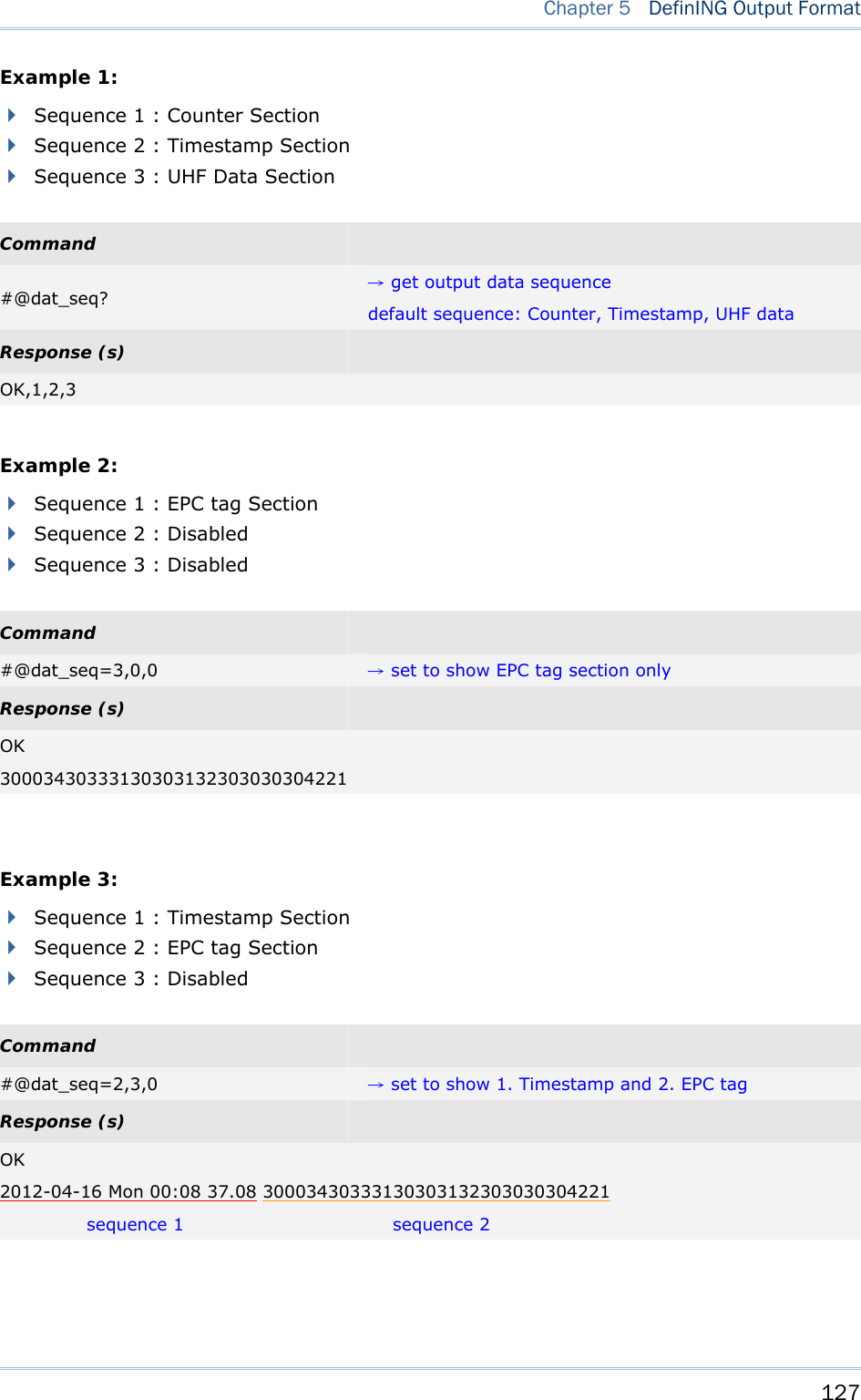
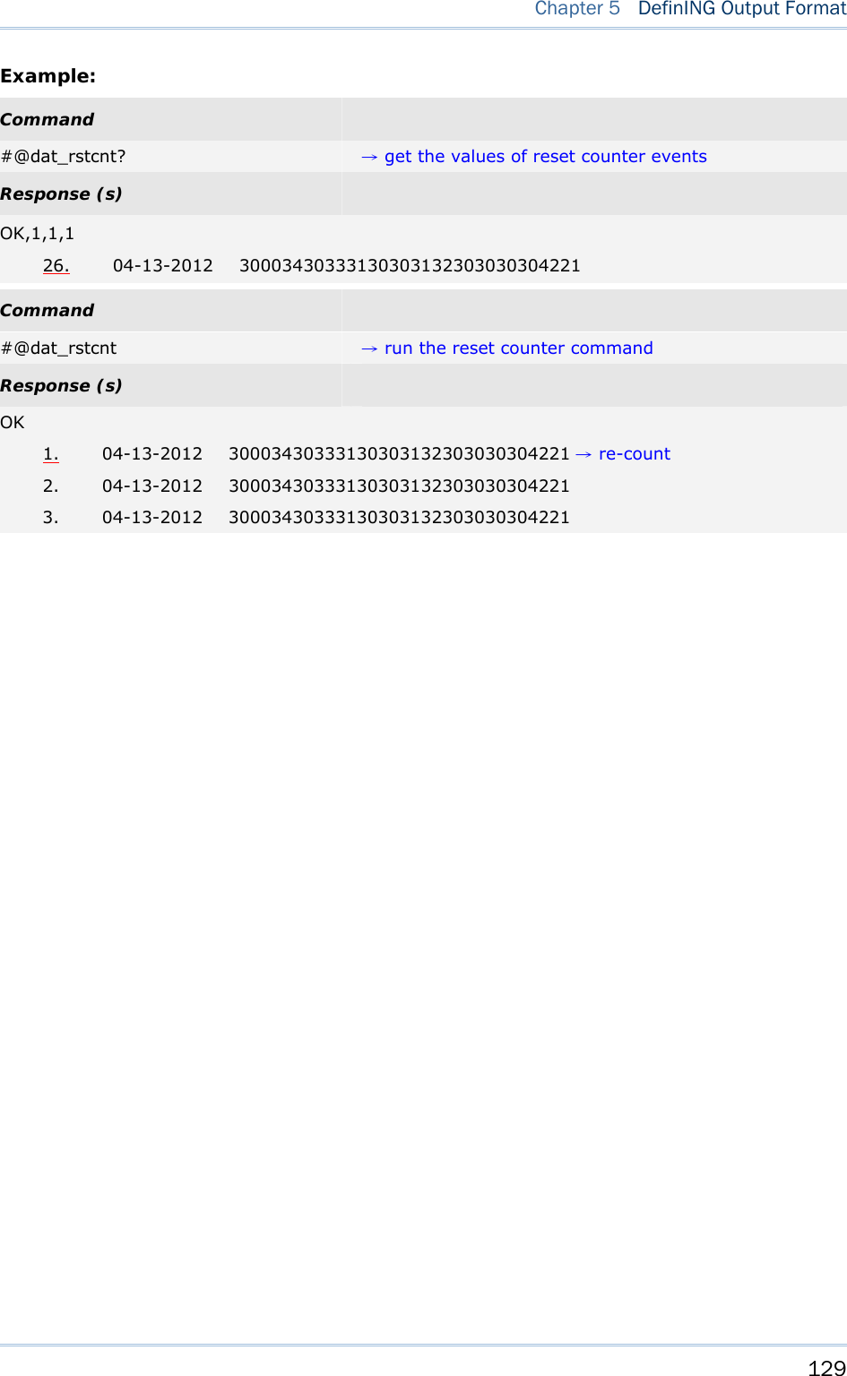
![128 1800 Series Handheld RFID Reader Reference Manual 5.2.1 DATA COUNTER SECTION Define a serial number to output data. The serial number would be specified in 6 digits beginning from 000001. When the counter is up to 999999, it will be reset to 000001. Default Format: Reset Counter Event There are three events supported to reset the counter. With the parameter set to ‘1’, the counter will be reset when the event occurs. Command: #@dat_rstcnt?\r Purpose Get the Setting of Reset Counter Event Response OK,[m],[n],[o]\r (Default m= ‘1’, n= ‘0’, o= ‘1’) Reset Event Enable Disable [m] Reset Counter command accepted ‘1’ ‘0’ [n] UHF Power On ‘1’ ‘0’ [o] new Bluetooth® connection established ‘1’ ‘0’ ERR,[code]\r #@dat_rstcnt=[m],[n.],[o]\r Purpose Enable/Disable Counter Reset Event Response OK\r ERR,[code]\r #@dat_rstcnt\r Purpose Reset Data Counter Response OK\r ERR,[code]\r Note: Besides the configurable events above, Data Counter will also be reset when system powers up.](https://usermanual.wiki/CipherLab/1862/User-Guide-2462059-Page-140.png)
![130 1800 Series Handheld RFID Reader Reference Manual Counter Padding For data display alignment purposes, you can define padding characters to show the counter value with fixed 6-digit. Characters to be padded or retrieved are shown in Hexadecimal. Please refer to ASCII Table. The default value is 0x20 (space) for ‘20’ displayed. Command: #@dat_cntpad?\r Purpose Get the Setting of Pad Counter Character Response OK,[m]\r (Default m= ‘20’ - 0x20 space) [m]: Character to be padded before data counter, shown in Hexadecimal value. ERR,[code]\r #@dat_cntpad=[m]\r Purpose Set the Character to be Padded before Counter Response OK\r ERR,[code]\r Example: Command #@dat_cntpad? →get counter padding Response (s) OK,20 →20 is for ‘space’ referred to ASCII table ‘0x20’ 10. 04-13-2012 30003430333130303132303030304221 Command #@dat_cntpad=2a →set counter padding to 2a as ‘*’ referred to ASCII table ‘0x2a’ Response (s) OK **** 11. 04-13-2012 30003430333130303132303030304221](https://usermanual.wiki/CipherLab/1862/User-Guide-2462059-Page-142.png)
![131 Chapter 5 DefinING Output Format 5.2.2 TIME STAMP SECTION Time Stamp section is divided into 7 fields as year, month, day, weekday, hour, minute and second. Separators can be defined among fields to make more clear presentation. Up to 6 separators can be specified to Time Stamp section. Default Format: Time Stamp Sequence Issue “#@dat_tseq=” command to configure the fields of Time Stamp section. You can set the parameter to ‘0’ to disable the field. Command: #@dat_tseq?\r Purpose Get the Sequence Settings of Time Stamp Section Response OK,[m],[n],[o],[p],[q],[r],[s]\r (Default m= ‘1’, n= ‘2’’, o= ‘3’, p= ‘0’, q= ‘5’, r= ‘6’, s= ‘7’) [m]: Time Data Type in Field 1 [n]: Time Data Type in Field 2 [o]: Time Data Type in Field 3 [p]: Time Data Type in Field 4 [q]: Time Data Type in Field 5 [r]: Time Data Type in Field 6 [s]: Time Data Type in Field 7 [m]~[s] Field ‘0’ Disable this Field ‘1’ Year ‘2’ month ‘3’ day ‘4’ weekday ‘5’ Hour ‘6’ Minute ‘7’ second ERR,[code]\r #@dat_tseq=[m],[n],[o],[p],[q],[r],[s]\r](https://usermanual.wiki/CipherLab/1862/User-Guide-2462059-Page-143.png)
![132 1800 Series Handheld RFID Reader Reference Manual Purpose Set the Sequences of Field in Time Stamp Section Response OK\r [m]: Time Data Type in Field 1. Default = ‘1’ [n]: Time Data Type in Field 2. Default = ‘2’ [o]: Time Data Type in Field 3. Default = ‘3’ [p]: Time Data Type in Field 4. Default = ‘0’ [q]: Time Data Type in Field 5. Default = ‘5’ [r]: Time Data Type in Field 6. Default = ‘6’ [s]: Time Data Type in Field 7. Default = ‘7’ ERR,[code]\r Example: Command #@dat_tseq=1,2,3,0,0,0,0 →set to show year, month and day only Response (s) OK 24. 2012-04-12 30003430333130303132303030304221 Command #@dat_tseq=2,3,1,0,0,0,0 →change the sequences of year, month and day Response (s) OK 25. 04-13-2012 30003430333130303132303030304221 Note: If the field is disabled, its following separator will also be ignored.](https://usermanual.wiki/CipherLab/1862/User-Guide-2462059-Page-144.png)
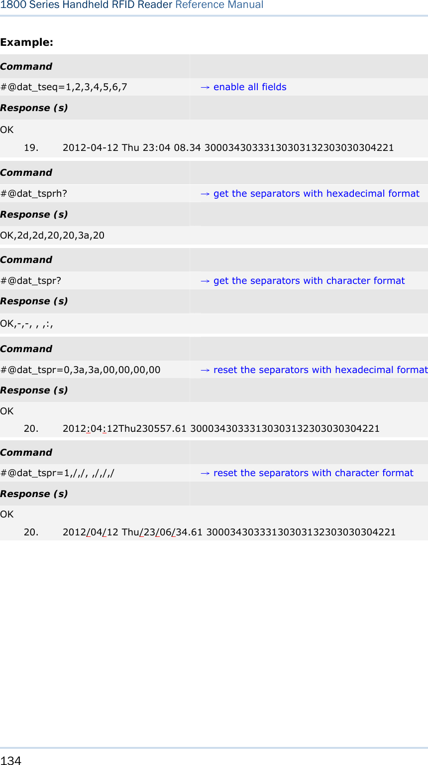
![133 Chapter 5 DefinING Output Format Time Stamp Separators You can configure the separator between fields. The separator to be configured or retrieved can present in ASCII characters or hexadecimal numbers. Refer to ASCII Table Command: #@dat_tsprh?\r, #@dat_tspr?\r Purpose Get the Separators of Field in Time Stamp Section Request #@dat_tsprh?\r //Response data will be shown in Hexadecimal value. #@dat_tspr?\r //Response data will be shown in character. Response OK,[m],[n],[o],[p],[q],[r]\r [m]: separator follows field1. Default= ‘2D’ (‘-’) [n]: separator follows field2. Default= ‘2D’ (‘-’) [o]: separator follows field3. Default= ‘20’ (‘ ’) [p]: separator follows field4. Default= ‘20’ (‘ ’) [q]: separator follows field5. Default= ‘3A’ (‘:’) [r]: separator follows field6. Default= ‘20’ (‘ ’) ERR,[code]\r #@dat_tspr=[m],[n],[o],[p],[q],[r],[s]\r Purpose Set the Separators of Field in Time Stamp Section Request #@dat_tspr=[m],[n],[o],[p],[q],[r],[s]\r [m]: input data format, ‘0’- in Hexadecimal, ‘1’- in character [n]: separator follows field1 [o]: separator follows field2 [p]: separator follows field3 [q]: separator follows field4 [r]: separator follows field5 [s]: separator follows field6 Response OK\r ERR,[code]\r Note: Input ‘00’ (hexadecimal) to clear the inputted data.](https://usermanual.wiki/CipherLab/1862/User-Guide-2462059-Page-145.png)
![135 Chapter 5 DefinING Output Format Year For year output field, you can define it as 2 digits or 4 digits. Command: #@dat_tyear?\r Purpose Get the Setting of Year Field Response OK,[m]\r (Default m= ‘0’.) [m]: Year format. 0 – 2 digits, 1 – 4 digits (shown as ‘20xx’). ERR,[code]\r #@dat_tyear=[m]\r Purpose Set the Year Field Response OK\r [m]: Year format. m= ‘0’ is for 2 digits, m= ‘1’ is for 4 digits (shown as ‘20xx’). ERR,[code]\r Example: Command #@dat_tyear? →default format for year is 2 digits Response (s) OK,0 3. 12-04-12 05:44 59.47 30003430333130303132303030304221 Command #@dat_tyear=1 →set year format to 4 digits Response (s) OK 4. 2012-04-12 05:44 59.47 30003430333130303132303030304221](https://usermanual.wiki/CipherLab/1862/User-Guide-2462059-Page-147.png)
![136 1800 Series Handheld RFID Reader Reference Manual Time You can enable this function to display time in seconds with the scale of two digits to the right of the decimal point if second field is enabled. Command: #@dat_tms?\r Purpose Get Time Format Response OK,[m]\r (Default m= ‘1’) [m]: Display time in seconds with two digits after the decimal point. 0 – Disable, 1 – Enable ERR,[code]\r #@dat_tms=[m]\r Purpose Set to Display Time Request #@dat_tms=[m]\r [m]: Display time in seconds with two digits after the decimal point. 0 – Disable, 1 – Enable Response OK\r ERR,[code]\r Example: Command #@dat_tms? →get the displaying format of seconds Response (s) OK,1 5. 2012-04-12 05:44 59.47 30003430333130303132303030304221 display↑ time in seconds with two digits after the decimal point Command #@dat_tms=0 →set to display time in seconds without decimals Response (s) OK 6. 2012-04-12 05:44 59 30003430333130303132303030304221](https://usermanual.wiki/CipherLab/1862/User-Guide-2462059-Page-148.png)
![137 Chapter 5 DefinING Output Format 5.2.3 EPC TAG SECTION The EPC tag section is divided into 5 fields as PC, EPC, CRC, Memory Data and Data Length. Separators can be defined among fields for clarity. Up to 4 separators can be specified for this section. Default Format: Command: #@dat_rfseq?\r Purpose Get the Sequence Setting of EPC Tag Data Section Response OK,[m],[n],[o],[p],[q]\r [m]: EPC Tag Data in Field 1 (default: ‘2’ – PC) [n]: EPC Tag Data in Field 2 (default: ‘3’ – EPC) [o]: EPC Tag Data in Field 3 (default: ‘1’ – CRC) [p]: EPC Tag Data in Field 4 (default: ‘4’ – Memory Data) [q]: EPC Tag Data in Field 5 (default: ‘0’ – Disable) [m]~[q] Description ‘0’ Disable this Field ‘1’ CRC ‘2’ PC ‘3’ EPC ‘4’ Memory Data This field only appears when RFID function is set to “Read Tag Memory” ‘5’ Data Length ERR,[code]\r #@dat_rfseq=[m],[n],[o],[p],[q]\r Purpose Set the Sequence of Each Field in EPC Tag Data Section Response OK\r ERR,[code]\r Example: Command #@rf_func? →get RFID function](https://usermanual.wiki/CipherLab/1862/User-Guide-2462059-Page-149.png)
![138 1800 Series Handheld RFID Reader Reference Manual Default is inventory Response (s) OK,0 18. 2012-04-12 Fri 04:00 55.95 30003430333130303132303030304221 Command #@dat_rfseq? →get the sequence of RFID Data Default sequence is PC, EPC and then CRC Response (s) OK,2,3,1,4,0 19. 2012-04-12 Fri 04:00 55.95 3000 343033313030313230303030 4221 PC + EPC + CRC Command #@dat_rfseq=3,0,0,0,0 → only show EPC Response (s) OK 20. 2012-04-12 Fri 04:00 55.95 343033313030313230303030 EPC UHF Data Separators The separator to be configured or retrieved can present in ASCII characters or hexadecimal numbers. Refer to ASCII Table. Command: #@dat_rfsprh?\r, #@dat_rfspr?\r Purpose Get the Separators of Each field in EPC Tag Data Section Request #@dat_rfsprh?\r Response data will be shown in Hexadecimal value #@dat_rfspr?\r Response data will be shown in character Response OK,[m],[n],[o],[p]\r [m]: separator follows field1. Default= ‘00’ (NULL) [n]: separator follows field2. Default= ‘00’ (NULL) [o]: separator follows field3 . Default= ‘00’ (NULL) [p]: separator follows field4 . Default= ‘00’ (NULL) ERR,[code]\r #@dat_rfspr=[m],[n],[o],[p],[q]\r](https://usermanual.wiki/CipherLab/1862/User-Guide-2462059-Page-150.png)
![139 Chapter 5 DefinING Output Format Purpose Set the Separators of Each field in EPC Tag Data Section Request #@dat_ rfspr=[m],[n],[o],[p],[q]\r [m]: input data format, ‘0’- in Hexadecimal, ‘1’- in character [n]: separator between field1 and field2 [o]: separator between field2 and field3 [p]: separator between field3 and field4 [q]: separator between field4 and field5 Response OK\r ERR,[code]\r Note: Input ‘00’ (hexadecimal) to clear the inputted data. Example: Command #@dat_rfspr? →get the separators in character format Response (s) OK, Command #@dat_rfsprh? →get the separators in hexadecimal format Response (s) OK,00,00,00,00 21. 2012-04-12 Fri 04:00 55.95 34303331303031323030303030004221 Command #@dat_rfsprh=0,2d,2d,2d,2d →reset the separators using hexadecimal format e.g. 2d is specified for ‘-’ Response (s) OK 22. 2012-04-12 Fri 04:00 55.95 343033313030313230303030-3000-4221- Command #@dat_rfsprh=1,/,/,/,/ →reset the separators using character format Response (s) OK 23. 2012-04-12 Fri 04:00 55.95 343033313030313230303030/3000/4221/ Note: If a specific field is disabled, its following separator will be ignored.](https://usermanual.wiki/CipherLab/1862/User-Guide-2462059-Page-151.png)
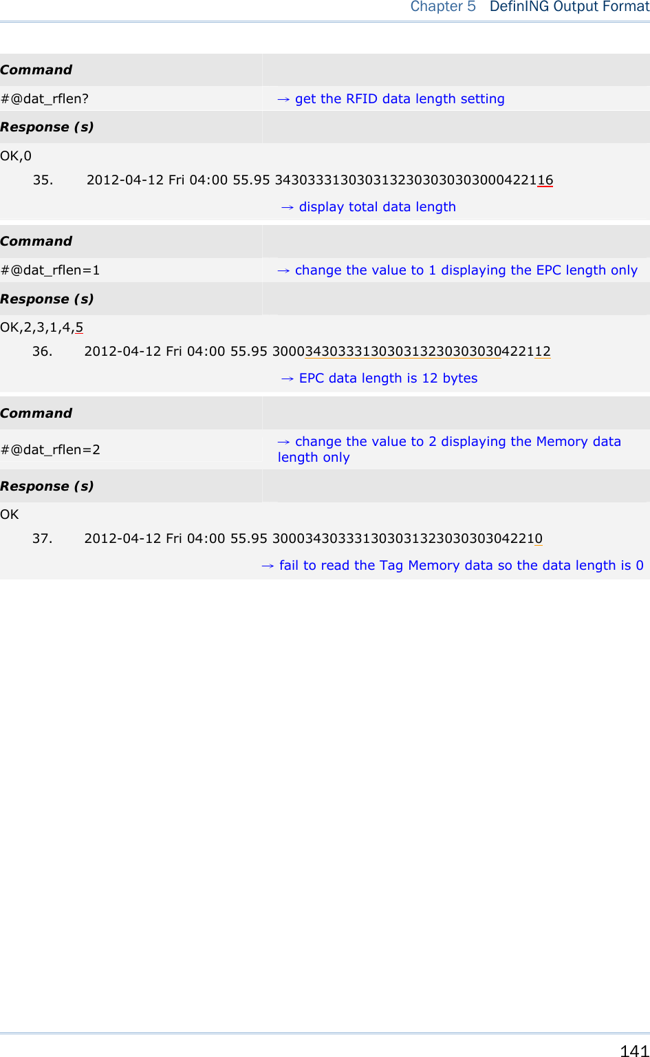
![140 1800 Series Handheld RFID Reader Reference Manual Data Length Enable the Data Length function to show the length for UHF Data, EPC and memory data. Command: #@dat_rflen?\r Purpose Get the Setting of UHF Data Length Response OK,[m]\r (Default m= ‘0’) [m]: Data Length Type ‘0’- Total UHF Data Length. Separators are not included. ‘1’- EPC Length ‘2’- Memory Data Length ERR,[code]\r Note: UHF data length is not related to the appearance of fields. For example, when the field is set to display EPC data only with data length set to “Total UHF Data Length”, data length will include PC and CRC data even though the two data fields are not displayed. #@dat_rflen=[m]\r Purpose Set the RFID Data Length Response OK\r ERR,[code]\r Example: Command #@dat_rfseq? →get the sequence of RFID data Response (s) OK,2,3,1,4,0 →default data length is ‘0’ not transmitted 33. 2012-04-12 Fri 04:00 55.95 34303331303031323030303030004221 Command #@dat_rfseq=2,3,1,4,5 →set to ‘5’ to display data length Response (s) OK,2,3,1,4,5 34. 2012-04-12 Fri 04:00 55.95 3430333130303132303030303000422116 →total data length is 16 bytes including PC (2 bytes), EPC (12 bytes), and (CRC 2 bytes)](https://usermanual.wiki/CipherLab/1862/User-Guide-2462059-Page-152.png)
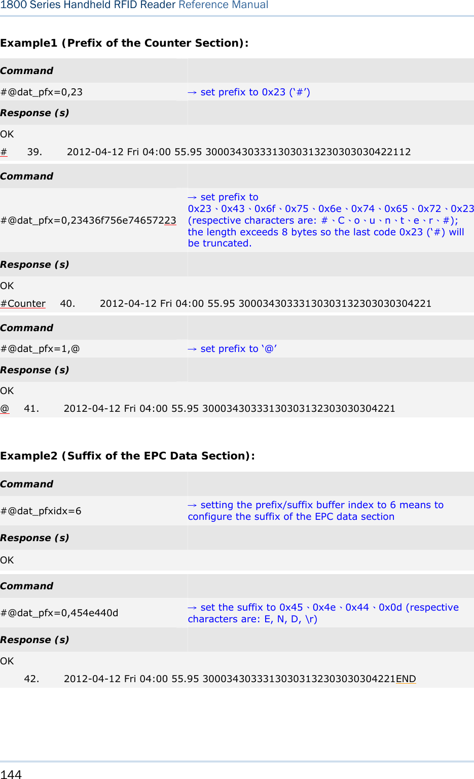
![142 1800 Series Handheld RFID Reader Reference Manual 5.3 PREFIX/SUFFIX CODE Prefix/Suffix codes can be utilized for applications like data section prompt string, separating string, carriage return or other auxiliary data-identification. Each data section has its own individual prefix/suffix codes up to 8 bytes. Prefix/Suffix Index For a prefix or suffix index, you have to specify for which section (e.g. Data Counter, Time Stamp or EPC Tag Data) you want to apply it to. Command: #@dat_pfxidx?\r Purpose Get Prefix/Suffix Buffer Index Response OK,[m]\r [m]: Prefix / Suffix Index [m] Description ‘1’ Prefix of Data Counter Section ‘2’ Suffix of Data Counter Section ‘3’ Prefix of Time Stamp Section ‘4’ Suffix of time Stamp Section ‘5’ Prefix of EPC Tag Data Section ‘6’ Suffix of EPC Tag Data Section ERR,[code]\r #@dat_pfxidx=[m]\r Purpose Specify Prefix/Suffix Buffer Index Response OK\r ERR,[code]\r](https://usermanual.wiki/CipherLab/1862/User-Guide-2462059-Page-154.png)
![143 Chapter 5 DefinING Output Format Prefix/Suffix Command: #@dat_pfxh?\r, #@dat_pfx?\r Purpose Get Prefix/Suffix Request #@dat_pfxh?\r Response data will be shown in Hexadecimal value #@dat_pfx?\r Response data will be shown in character Response OK,[m]\r [m]: Prefix/Suffix stored in the index-specified buffer ERR,[code]\r #@dat_pfx= [m],[n]\r Purpose Set Prefix/Suffix Response OK\r [m]: input data format, ‘0’- in Hexadecimal, ‘1’- in character [n]: Prefix/Suffix to be stored in the index-specified buffer ERR,[code]\r Default Prefix of Counter Section ‘00’ (NULL) Prefix of Time Stamp Section ‘20’ (SPACE) Prefix of EPC Tag Data Section ‘00’ (NULL) Suffix of Counter Section ‘2E’ (.) Suffix of Time Stamp Section ‘20’ (SPACE) Suffix of EPC Tag Data Section ‘0D’ (CR)](https://usermanual.wiki/CipherLab/1862/User-Guide-2462059-Page-155.png)
![145 Chapter 5 DefinING Output Format 5.4 OUTPUT EPC DATA VIA USB VIRTUAL COM Users can decide whether to output data via the USB Virtual COM port. Once the ‘m’ parameter of this command is set to ‘1’, the EPC data originally transmitted by Bluetooth® communications will be output by the USB Virtual COM port. Thus, Bluetooth® communications stop outputting the EPC data. Command: #@dat_2usb?\r Purpose Get the Setting Value Response OK,[m]\r [m]: Output EPC Data via USB Virtual COM ‘0’ Disable (default) ‘1’ Enable outputting EPC Data via USB Virtual COM ERR,[code]\r #@dat_2usb=[m]\r Purpose Specify the Setting Response OK\r ERR,[code]\r](https://usermanual.wiki/CipherLab/1862/User-Guide-2462059-Page-157.png)
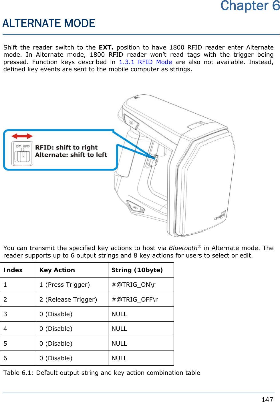
![148 1800 Series Handheld RFID Reader Reference Manual Output String Define the string first before defining the action to be executed. Command: #@dat_ostridx?\r Purpose Get Output String index Response OK,[m]\r (Default m= ‘1’) [m]: String Buffer Parameter 1~6 ERR,[code]\r #@dat_ostridx=[m]\r Purpose Set Output String index Response OK\r ERR,[code]\r Key Action Command: #@dat_ostrkey?\r Purpose Get Key Action of Output String Response OK,[m]\r [m]: Key Action [m] Action ‘0’ Disable ‘1’ Trigger key is pressed ‘2’ Trigger key is released ‘3’ F1 is pressed ‘4’ F1 is released ‘5’ F2 is pressed ‘6’ F2 is released ‘7’ F1+ Trigger key are pressed ‘8’ F2 + Trigger key are pressed ERR,[code]\r](https://usermanual.wiki/CipherLab/1862/User-Guide-2462059-Page-160.png)
![149 Chapter 6 Alternate Mode #@dat_ostrkey=[m]\r Purpose Set Key Action of Output String, refer to Table 6.1 Response OK\r ERR,[code]\r Output String Data Output strings have a maximum length of 10 characters and can be defined in Hexadecimal or in ASCII characters. Strings longer than 10 characters will be truncated. Command: #@dat_ostrh?\r, #@dat_ostr?\r Purpose Get Output String Request #@dat_ostrh?\r Response data will be shown in Hexadecimal value #@dat_ostr?\r Response data will be shown in character Response OK,[m]\r [m]: Data is stored in buffer. ERR,[code]\r #@dat_ostr=[m],[n]\r Purpose Set Output String, refer to Table 6.1 [m]: specify the data format, ‘0’- in Hexadecimal, ‘1’- in character [n]: Data to be stored in buffer Response OK\r ERR,[code]\r #@dat_ostr=1,#@iOSKBD\r Purpose This command is used to have the on-screen keyboard of iPad/iPhone showing up when the Bluetooth® connection type is HID. Response OK\r ERR,[code]\r Note: Specify ‘00’ (hexadecimal) to clear the input data.](https://usermanual.wiki/CipherLab/1862/User-Guide-2462059-Page-161.png)

![155 BEFORE UPGRADING Ensure the RFID reader has a fully charged battery prior to attempting a firmware upgrade. In order to avoid the data loss during firmware upgrade. Please save or upload all the data from the flash memory before beginning firmware upgrade. Command: Purpose Download Firmware Request #@sys_dlfw=[m]\r [m]: ‘0’ – Current interface ‘1’ – Bluetooth® ‘2’ – USB Response OK\r ERR,[code]\r Note: When the ‘OK’ response is received, please end HyperTerminal and run the ProgLoad.exe utility to begin firmware upgrade. Appendix I FIRMWARE UPGRADE](https://usermanual.wiki/CipherLab/1862/User-Guide-2462059-Page-167.png)
![156 1800 Series Handheld RFID Reader Reference Manual HOW TO UPGRADE FIRMWARE USE USB VIRTUAL COM 1) Use the provided USB cable to connect RFID Reader to the USB port of host computer. You will need to install USB cable driver first. 2) Refer to Using HyperTerminal for connecting with USB cable. 3) Issue “#@sys_dlfw=0” or “#@sys_dlfw=2”command. 4) End HyperTerminal. 5) Run the download utility “ProgLoad.exe” on the host computer. For the communication settings, select “RS-232/IrDA” and the correct COM port for Direct USB Virtual COM interface. Ignore the baud rate setting. For the file option, click [Browse] to select the target file e.g. U1860V*.SHX for firmware update. Click [OK]. 6) After upgrading, RFID Reader will restart automatically.](https://usermanual.wiki/CipherLab/1862/User-Guide-2462059-Page-168.png)

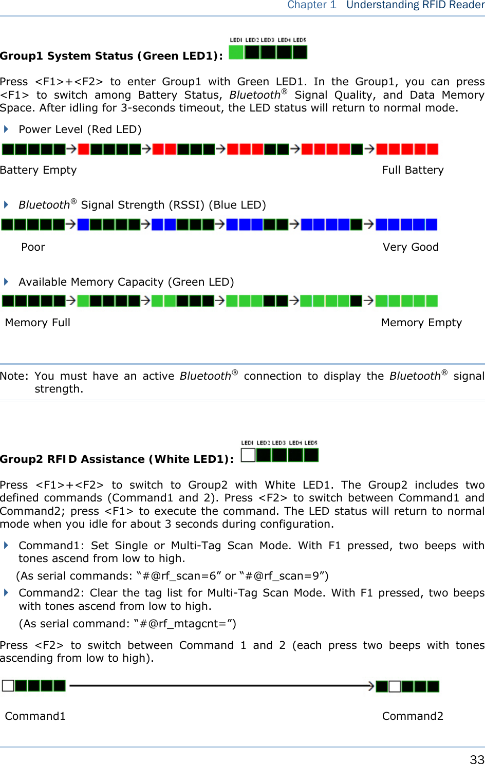
![159 0 1 2 3 4 5 6 7 0 DLE SP 0 @ P ` p 1 SOH DC1 ! 1 A Q a q 2 STX DC2 " 2 B R b r 3 ETX DC3 # 3 C S c s 4 EOT DC4 $ 4 D T d t 5 ENQ NAK % 5 E U e u 6 ACK SYN & 6 F V f v 7 BEL ETB ' 7 G W g w 8 BS CAN ( 8 H X h x 9 HT EM ) 9 I Y i y A LF SUB * : J Z j z B VT ESC + ; K [ k { C FF FS , < L \ l | D CR GS - = M ] m } E SO RS . > N ^ n ~ F SI US / ? O _ o DEL Appendix II ASCII TABLE](https://usermanual.wiki/CipherLab/1862/User-Guide-2462059-Page-171.png)