CipherLab 1862 Handheld RFID Reader User Manual 1800 RFID Reader
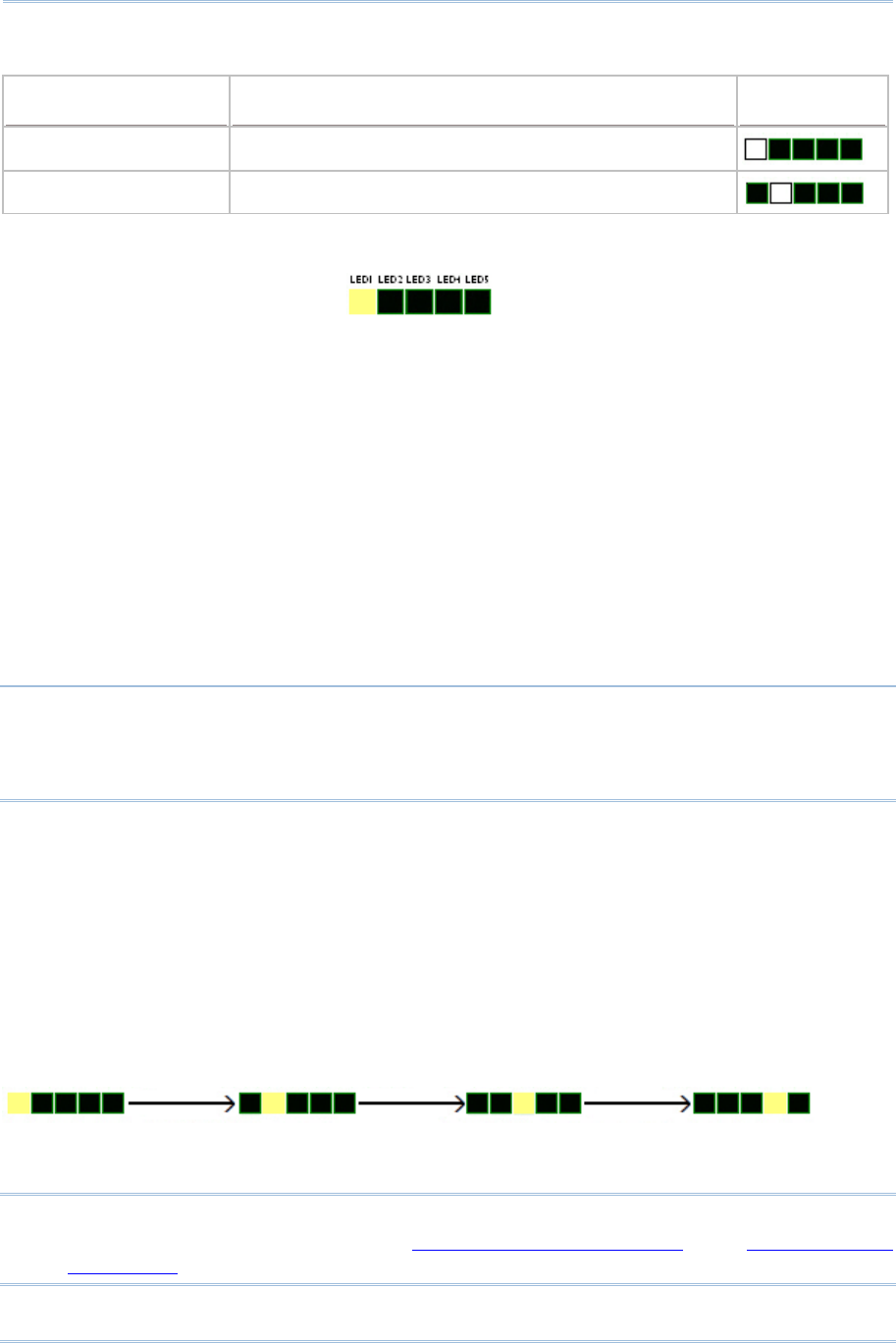
CipherLab Co., Ltd. Handheld RFID Reader 1800 RFID Reader
User Manual.pdf
1800 Series Handheld RFID Reade
r
For CP Series/8 Series/Universal
Version 1.04

Copyright © 2012~2013 CIPHERLAB CO., LTD.
All rights reserved
The software contains proprietary information of CIPHERLAB CO., LTD.; it is provided
under a license agreement containing restrictions on use and disclosure and is also
protected by copyright law. Reverse engineering of the software is prohibited.
Due to continued product development this information may change without notice. The
information and intellectual property contained herein is confidential between CIPHERLAB
and the client and remains the exclusive property of CIPHERLAB CO., LTD. If you find
any problems in the documentation, please report them to us in writing. CIPHERLAB
does not warrant that this document is error-free.
No part of this publication may be reproduced, stored in a retrieval system, or
transmitted in any form or by any means, electronic, mechanical, photocopying,
recording or otherwise without the prior written permission of CIPHERLAB CO., LTD.
For product consultancy and technical support, please contact your local sales
representative. Also, you may visit our web site for more information.
The CipherLab logo is a registered trademark of CIPHERLAB CO., LTD.
All brand, product and service, and trademark names are the property of their registered
owners.
The editorial use of these names is for identification as well as to the benefit of the
owners, with no intention of infringement.
CIPHERLAB CO., LTD.
Website: http://www.cipherlab.com

FOR USA
This equipment has been tested and found to comply with the limits for a Class B digital
device, pursuant to Part 15 of the FCC Rules. These limits are designed to provide
reasonable protection against harmful interference in a residential installation. This
equipment generates, uses and can radiate radio frequency energy and, if not installed
and used in accordance with the instructions, may cause harmful interference to radio
communications. However, there is no guarantee that interference will not occur in a
particular installation. If this equipment does cause harmful interference to radio or
television reception, which can be determined by turning the equipment off and on, the
user is encouraged to try to correct the interference by one or more of the following
measures:
Reorient or relocate the receiving antenna.
Increase the separation between the equipment and receiver.
Connect the equipment into an outlet on a circuit different from that to which the
receiver is connected.
Consult the dealer or an experienced radio/TV technician for help.
This device complies with Part 15 of the FCC Rules. Operation is subject to the following
two conditions: (1) This device may not cause harmful interference, and (2) this device
must accept any interference received, including interference that may cause undesired
operation.
FCC Caution: Any changes or modifications not expressly approved by the party
responsible for compliance could void the user's authority to operate this equipment.
This transmitter must not be co-located or operating in conjunction with any other
antenna or transmitter.
Radiation Exposure Statement:
This equipment complies with FCC radiation exposure limits set forth for an uncontrolled
environment. This equipment should be installed and operated with minimum distance
20cm between the radiator & your body.
IMPORTANT NOTICES

FOR EUROPE
This device complies with the essential requirements of the R&TTE Directive 1999/5/EC.
The following test methods have been applied in order to prove presumption of
conformity with the essential requirements of the R&TTE Directive 1999/5/EC:
- EN 60950-1: 2006+A11:2009
Safety of Information Technology Equipment
- EN 301 908-1 V4.2.1: 2010
Electromagnetic compatibility and Radio spectrum Matters (ERM); Base Stations (BS),
Repeaters and User Equipment (UE) for IMT-2000 Third-Generation cellular networks;
Part 1: Harmonized EN for IMT-2000, introduction and common requirements, covering
essential requirements of article 3.2 of the R&TTE Directive
- EN 301 908-1 V5.2.1: 2011
Electromagnetic compatibility and Radio spectrum Matters (ERM); Base Stations (BS),
Repeaters and User Equipment (UE) for IMT-2000 Third-Generation cellular networks;
Part 1: Harmonized EN for IMT-2000, introduction and common requirements, covering
essential requirements of article 3.2 of the R&TTE Directive
- EN 301 489-1 V1.8.1: 2008
Electromagnetic compatibility and Radio Spectrum Matters (ERM); ElectroMagnetic
Compatibility (EMC) standard for radio equipment and services; Part 1: Common
technical requirements
- EN 301 489-3 V1.4.1 2002
Electromagnetic compatibility and Radio Spectrum Matters (ERM); ElectroMagnetic
Compatibility (EMC) standard for radio equipment and services; Part 3: Specific
conditions for Short-Range Devices (SRD) operating on frequencies between 9 kHz and
40 GHz
- EN 301 489-17 V2.1.1 2009
Electromagnetic compatibility and Radio spectrum Matters (ERM); ElectroMagnetic
Compatibility (EMC) standard for radio equipment and services; Part 17: Specific
conditions for 2,4 GHz wideband transmission systems and 5 GHz high performance
RLAN equipment
- EN 300 328 V1.7.1: 2006
Electromagnetic compatibility and Radio spectrum Matters (ERM); Wideband
Transmission systems; Data transmission equipment operating in the 2,4 GHz ISM band
and using spread spectrum modulation techniques; Harmonized EN covering essential
requirements under article 3.2 of the R&TTE Directive
- EN 302 208-1 V1.4.1: 2011
Electromagnetic compatibility and Radio spectrum Matters (ERM); Radio Frequency
Identification Equipment operating in the band 865 MHz to 868 MHz with power levels up
to 2 W; Part 1: Technical requirements and methods of measurement
- EN 302 208-2 V1.3.1: 2010
Electromagnetic compatibility and Radio spectrum Matters (ERM); Radio Frequency
Identification Equipment operating in the band 865 MHz to 868 MHz with power levels up
to 2 W; Part 2: Harmonized EN covering essential requirements of article 3.2 of the
R&TTE Directive
- EN50371 : 2002
Generic standard to demonstrate the compliance of low power electronic and electrical
apparatus with the basic restrictions related to human exposure to electromagnetic fields
(10 MHz - 300 GHz) -- General public

SAFETY PRECAUTIONS
RISK OF EXPLOSION IF BATTERY IS REPLACED BY AN INCORRECT TYPE.
DISPOSE OF USED BATTERIES ACCORDING TO THE INSTRUCTIONS.
The use of any battery or charging devices, which are not originally sold or
manufactured by CipherLab, will void your warranty and may cause damage to
human body or the product itself.
DO NOT disassemble, incinerate or short circuit the battery.
DO NOT expose the reader or the battery to any flammable sources.
For green-environment issue, it's important that battery should be recycled in a
proper way.
Under no circumstances, internal components are self-serviceable.
The charging uses an AC power adapter. A socket outlet shall be installed near the
equipment and shall be easily accessible. Make sure there is stable power supply for
the reader or its peripherals to operate properly.
CARE & MAINTENANCE
This reader is intended for industrial use. The reader is rated IP64, however, it may
do damage to the reader when being exposed to extreme temperatures or soaked
wet.
DO NOT use any pointed or sharp object to move any cover that is included on the
reader.
If you want to put away the reader for a period of time, download the collected data
to a host computer, and then take out the battery pack. Store the reader and battery
pack separately.
When the reader resumes its work, the battery will take a certain time to become
fully charged.
If you shall find the reader malfunctioning, write down the specific scenario and
consult your local sales representative.

Version Date Notes
1.04 Nov. 13, 2014 Modified: 1.5 – Command Beep is disabled by default
Modified: 4.3.3 – #@rf_sepc1 corrected to #@rf_sepcl (example
code)
Modified: 4.6.1 – default Q value for 1862 added
Modified: 4.6.2 – default Output Power level for 1862 added
Modified: 5.2.3 EPC Tag Section – descriptions for
“#@dat_rfspr=” added
Modified: Specifications – 1862 added
1.03 Oct. 07, 2013 Modification: 1.1.4 Low Battery Alarm – Charging status
definition added to SYS_BATTERY command
Modification: 1.8 Event events sent via USB & bit 9 definition
added to SYS_EVT command
Modification: Appendix IV Status Code – code table updated
1.02 May. 27, 2013 Modification: 1.2.1 Transmit Buffer –
Transmission Buffer
commands revised/added
(SYS_TXBEN, SYS_TXBUP,
SYS_TXBCLR)
Modification: 1.2.2 Memory Mode -
SYS_MEMUP command
revised
New: 1.8 Event added (SYS_EVT command)
Modification: 4.5.2 Read/Write Tag – “RF_RWIDX” memory
bank value revised
New: 4.6.1 Applications in Multiple Tags Environment –
RF_Q
command added
New: 4.6.2 Adjustment for Output Power Level of the
Reader – RF_PLV command added
New: 5.4 Output EPC Data via USB Virtual COM DAT_2USB
command added
Modification: Ch. 6 Alternate Mode -
#@dat_ostr=1,#@iOSKBD
command added
1.01 Dec. 17, 2012 Revised according TC manual
1.00 Sep. 18, 2012 Initial Release
RELEASE NOTES

CONTENTS
IMPORTANT NOTICES ...................................................................................................................... - 3 -
For USA .......................................................................................................................................... - 3 -
For Europe ..................................................................................................................................... - 4 -
Safety Precautions ........................................................................................................................ - 6 -
Care & Maintenance ..................................................................................................................... - 6 -
RELEASE NOTES.............................................................................................................................. - 7 -
INTRODUCTION .................................................................................................................................... 1
Getting Familiar with RFID Reader................................................................................................... 2
Overview ....................................................................................................................................... 2
Installing the Battery.................................................................................................................... 3
Charging the Battery .................................................................................................................... 4
Charging the Battery via Charger ................................................................................................ 5
Inside the Package............................................................................................................................ 6
Features............................................................................................................................................. 6
Accessories........................................................................................................................................ 6
QUICK START ....................................................................................................................................... 7
Power on RFID Reader...................................................................................................................... 7
Connecting USB Cable ...................................................................................................................... 7
Issuing Commands via USB Connection.......................................................................................... 8
Using HyperTerminal.................................................................................................................... 8
Confirming the USB Connection................................................................................................12
Default Settings...............................................................................................................................14
Save User Settings as Defaults.................................................................................................14
Restore User/Factory Defaults..................................................................................................14
Reader Switch .................................................................................................................................15
Combining with a Mobile Computer...............................................................................................16
1800 Configuration.........................................................................................................................17
UNDERSTANDING RFID READER.......................................................................................................19
1.1 Power.........................................................................................................................................21
1.1.1 Power ON ..........................................................................................................................21
1.1.2 Power OFF.........................................................................................................................21
1.1.3 Power Saving Mode .........................................................................................................22
1.1.4 Low Battery Alarm ............................................................................................................23
1.2 Memory .....................................................................................................................................24
1.2.1 Transmit Buffer ................................................................................................................24
1.2.2 Memory Mode ..................................................................................................................27
1.3 Function Keys ...........................................................................................................................31
1.3.1 RFID Mode ........................................................................................................................32
1.3.2 Bluetooth® Pairing Mode .................................................................................................35

1800 Series Handheld RFID Reader Reference Manual
1.3.3 Alternate Mode.................................................................................................................36
1.4 LED Indicators........................................................................................................................... 37
1.4.1 General Mode...................................................................................................................37
1.4.2 Function Key Mode ..........................................................................................................39
1.4.3 Bluetooth® Pairing Mode .................................................................................................39
1.5 Beeper.......................................................................................................................................40
1.6 Vibrator......................................................................................................................................44
1.7 RTC ............................................................................................................................................45
1.8 Event..........................................................................................................................................46
COMMUNICATION INTERFACE...........................................................................................................47
2.1 USB Interface............................................................................................................................48
2.2 Bluetooth® Connection Type....................................................................................................49
2.3 Bluetooth® SPP Slave...............................................................................................................50
2.4 Bluetooth® SPP Master ............................................................................................................51
2.4.1 Activate Bluetooth® SPP Master Mode...........................................................................51
2.5 Bluetooth® HID..........................................................................................................................52
2.5.1 Activate Bluetooth® HID & Select Keyboard Type..........................................................52
2.5.2 Keyboard Settings............................................................................................................55
2.5.3 Inter-Character Delay .......................................................................................................60
2.5.4 Inter-Function Delay.........................................................................................................60
2.5.5 HID Character Transmit Mode.........................................................................................60
2.6 USB VCOM and HID via 3610 .................................................................................................. 61
2.6.1 Activate USB VCOM and HID & Select Keyboard Type...................................................62
2.6.2 HID Keyboard Settings.....................................................................................................65
2.6.3 Inter-Character Delay .......................................................................................................70
2.6.4 Inter-Function Delay.........................................................................................................70
2.6.5 HID Character Transmit Mode.........................................................................................70
SETTING UP A WPAN CONNECTION ..................................................................................................71
3.1 Connecting via Bluetooth® Dongle .......................................................................................... 72
3.1.1 Change Interface..............................................................................................................72
3.1.2 Configure Related Settings..............................................................................................73
3.1.3 Bluetooth® HID and SPP Slave........................................................................................77
3.1.4 Bluetooth® SPP Master....................................................................................................85
3.2 Connecting via 3610................................................................................................................89
3.2.1 Connect to 3610 ..............................................................................................................89
3.2.2 USB HID via 3610 Connection ........................................................................................89
3.2.3 USB VCOM via 3610 Connection ....................................................................................91
3.3 Disconnection ...........................................................................................................................92
3.3.1 Break a Connection..........................................................................................................92
3.3.2 Reset a Connection..........................................................................................................92
SCANNING UHF RFID TAG .................................................................................................................93
4.1 Scan Mode ................................................................................................................................94
4.2 Scan Time .................................................................................................................................96
4.2.1 Timeout.............................................................................................................................96
4.2.2 Delay Time ........................................................................................................................97
4.3 Filter...........................................................................................................................................98

1800 Series Handheld RFID Reader Reference Manual
4.3.1 EPC Encoding Scheme.....................................................................................................99
4.3.2 Affected Tag of Included/Excluded EPC Filter..............................................................101
4.3.3 Included EPC ..................................................................................................................102
4.3.4 Excluded EPC..................................................................................................................106
4.4 Multi-Tag..................................................................................................................................110
4.4.1 Counter ...........................................................................................................................110
4.4.2 Counter Reload ..............................................................................................................112
4.4.3 Multi-Tag Beep ...............................................................................................................113
4.5 Access Tag ..............................................................................................................................114
4.5.1 Tag Memory ....................................................................................................................114
4.5.2 Read/Write Tag ..............................................................................................................116
4.6 Advanced Settings..................................................................................................................121
4.6.1 Applications in Multiple Tags Environment ..................................................................121
4.6.2 Adjustment for Output Power Level of The Reader......................................................122
DEFINING OUTPUT FORMAT............................................................................................................123
5.1 Output Format.........................................................................................................................124
5.2 Format Editing for Hexadecimal and Raw Data....................................................................126
5.2.1 Data Counter Section.....................................................................................................128
5.2.2 Time stamp Section .......................................................................................................131
5.2.3 EPC Tag Section .............................................................................................................137
5.3 Prefix/Suffix Code...................................................................................................................142
5.4 Output EPC Data via USB Virtual COM ..................................................................................145
ALTERNATE MODE...........................................................................................................................147
SPECIFICATIONS ..............................................................................................................................151
System ...........................................................................................................................................151
Communications ...........................................................................................................................151
Reader............................................................................................................................................151
Electrical Characteristics ..............................................................................................................152
Physical Characteristics................................................................................................................152
Environmental Characteristics .....................................................................................................153
Programming Support...................................................................................................................153
Accessories....................................................................................................................................153
FIRMWARE UPGRADE......................................................................................................................155
Before Upgrading ..........................................................................................................................155
How to Upgrade Firmware ............................................................................................................156
Use USB Virtual COM ...............................................................................................................156
Use Bluetooth® Dongle ............................................................................................................157
Use 3610..................................................................................................................................157
Use <F2>+<Trigger>................................................................................................................157

1800 Series Handheld RFID Reader Reference Manual
ASCII TABLE .....................................................................................................................................159
SCAN CODE......................................................................................................................................161
STATUS CODE ..................................................................................................................................163

1
1800 Series RFID Reader is designed to be the most flexible and reliable rugged RFID
gun with ergonomic form factor on the market. In terms of hardware specifically
designed to work as lightweight, ergonomic design, user-friendly LED display, easy
snap-on structure, storage capability and aggressive read-and-write range, 1800 Series
RFID Reader provides an efficient and complete solution for various applications when
combined with mobile computers using custom mount.
The Reader is easily integrated with mobile computers through Bluetooth® and with host
PC through USB. For the environment, 1800 Series RFID Reader is also equipped with
IP64 and 1.5m drop resistance features.
This manual serves to guide you through how to install, configure, and operate 1800
Series RFID Reader. We recommend you keep one copy of the manual at hand for quick
reference or maintenance purposes. To avoid any improper disposal or operation, please
read the manual thoroughly before use.
Refer to the following documents to get more information about UHF RFID and EPC
standards.
EPCTM Radio-Frequency Identity Protocols Class-1 Generation-2 UHF RFID Protocol for
Communications at 860 MHz-960MHz Version1.2.0
EPCTM Tag Data Standards Version1.6 (September 9, 2011)
They are available through GS1 organization, http://www.gs1.org.
Thank you for choosing CipherLab products!
INTRODUCTION
2
1800 Series Handheld RFID Reader Reference Manual
GETTING FAMILIAR WITH RFID READER
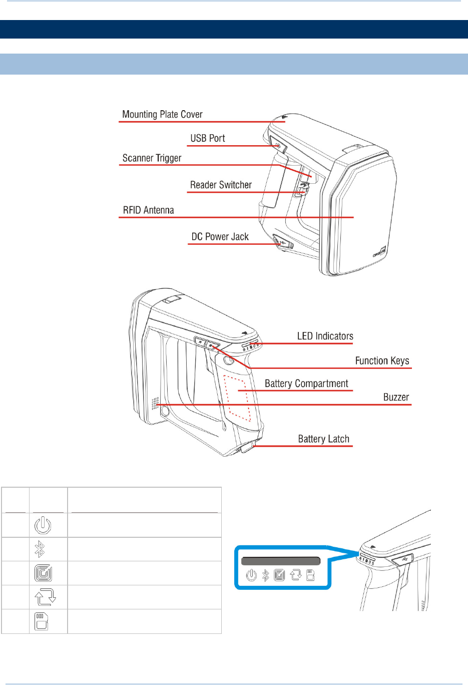
OVERVIEW
LED Icon Function
1 Power
2 Bluetooth® Communication
3 RFID Tag Access
4 Data Transmission
5 Reader Indicator/Memory Low
3
Introduction
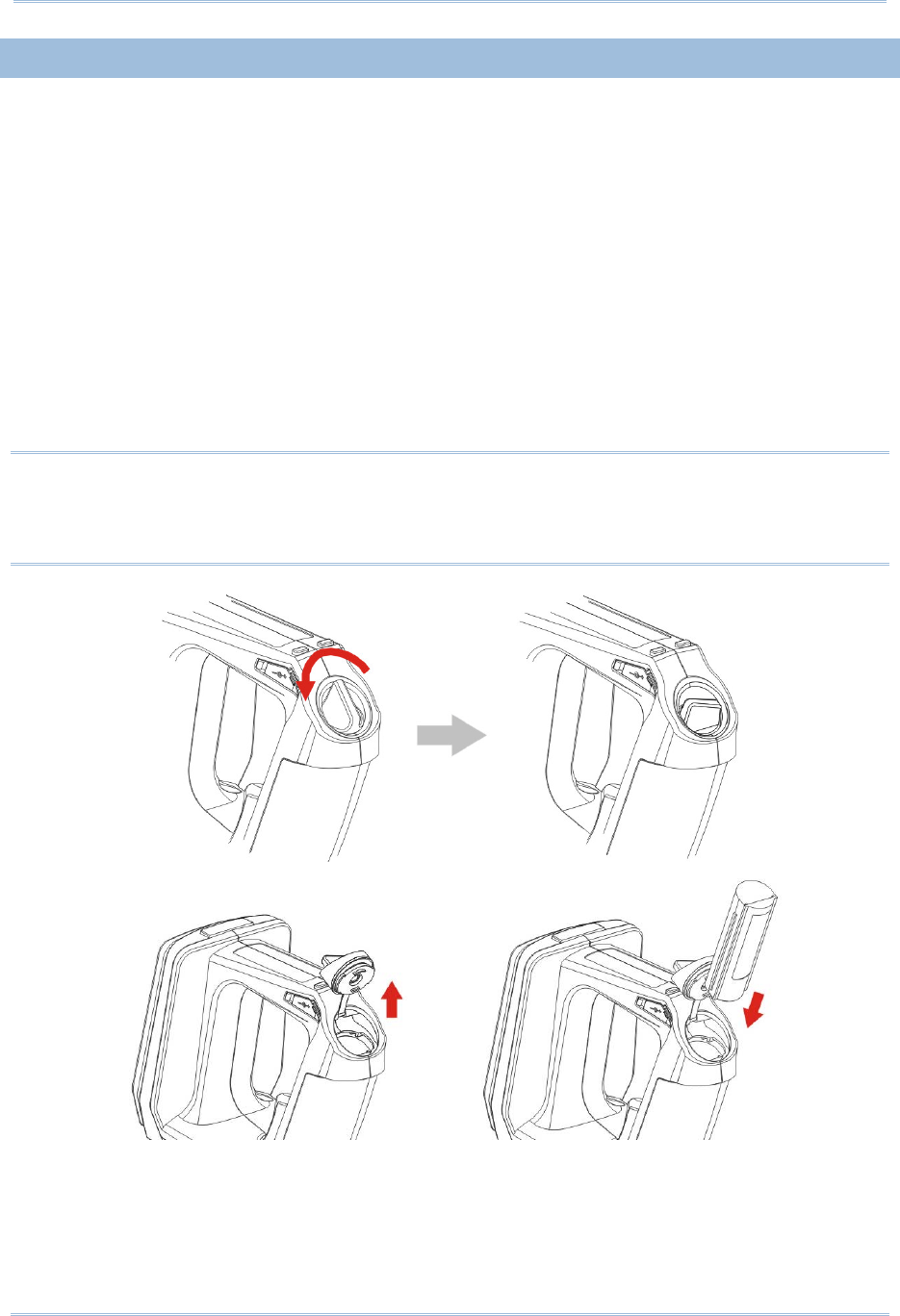
INSTALLING THE BATTERY
1) This RFID Reader is powered by a rechargeable 2500 mAh Li-ion battery. For
intensive data collection, we suggest it is better to purchase a spare battery for
non-stop operation.
2) Turn the battery latch to unlock position.
3) Remove the battery cover.
4) Insert the battery into the battery compartment so that the metal contacts on the
battery meet with the charging contacts inside the compartment. Make sure that the
battery fits snugly into the compartment.
5) Replace and turn the battery cover until it locks into place.
6) After the battery is charged successfully, press the trigger to power on the RFID
Reader. If you cannot power on the RFID Reader, please check that the battery is
charged and that it has been inserted correctly.
Note: (1) Any improper handling may reduce the battery life.
(2) When the main battery capacity becomes low, you need to charge the battery
as soon as possible or replace it with a charged one. Before replacing the battery,
make sure the power is turned off.
4
1800 Series Handheld RFID Reader Reference Manual
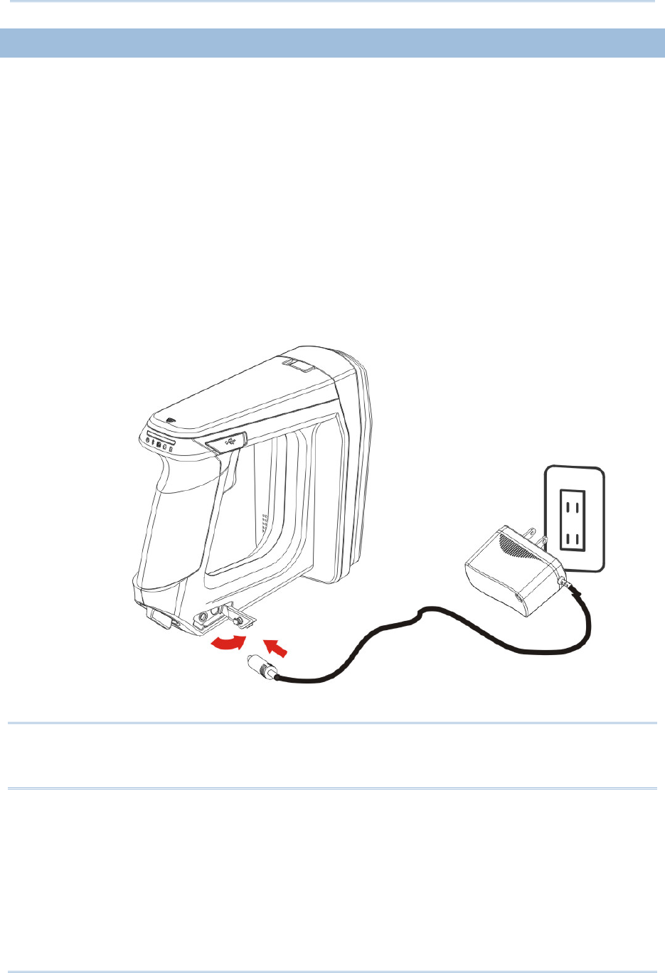
CHARGING THE BATTERY
New batteries are not fully charged. When you first receive the package, you will need to
charge the battery to full before using the RFID Reader. For RFID Reader, use the
adapter to charger the battery. It takes approximately 4 hours to charge the battery to
full.
1) Install the battery in RFID Reader.
2) Remove the cover to the power jack.
3) Connect the power cord to the power jack.
4) Connect the other end of the power cord to a suitable power outlet.
5) The RFID Reader LED1 will be flashing red during charging. When the charging is
done, the LED1 will flash green. If charging error occurs, the LED1 will turn solid red.
For example, a bad or missing battery.
Note: Battery charging stops when the temperature drops below 0°C or exceeds 40°C. It
is recommended to charge the battery at room temperature (18°C to 25°C) for
optimal performance.
5
Introduction
CHARGING THE BATTERY VIA CHARGER
Batteries may also be charged through the battery charger rather than in the reader
itself, allowing the user to continue using the reader at all times.
1) Connect the power supply cord to the power port located on the back of the charger.
2) Insert the battery to the end.
3) Confirm the lock bolt locks the battery securely.
4) Connect the other end of the power cord to a suitable power outlet.
5) Once the power and battery are ready, the LED indicator lights.
6) After finishing charge, press down the lock bolt to pull out the battery.
Status LED Function
Blue, Solid Charger power ON
Red, Solid Charging battery
Green, Solid Charging done
Blue/Red Ratio 0.5s:0.5s Error
Note: Battery charging stops when the temperature drops below 0°C or exceeds 40°C. It
is recommended to charge the battery at room temperature (18°C to 25°C) for
optimal performance.

6
1800 Series Handheld RFID Reader Reference Manual
INSIDE THE PACKAGE
The following items are included in the package. Save the box and packaging material for
future use in case you need to store or ship device.
1800 Series Handheld RFID Reader
Rechargeable Li-ion Battery
Direct USB Cable
Power Adapter
Product CD
Quick Guide
Test Tags
FEATURES
Ergonomic design - ruggedized yet streamlined
Built tough to survive multiple drops and sealed against moisture/dust to industrial
standard IP64
CipherLab Proprietary operating system
4MB flash for Memory Mode operation
Provides up to 2KB SRAM for reserve buffer while getting out of range over a wireless
personal area network (WPAN)
UHF RFID Reader (ISO-18000-6C/EPC Class1 Gen2 Standard)
Ambidextrous friendly Trigger
Connectivity includes Bluetooth® and USB
Programmable feedback including beeper and vibrator
Support user-friendly LED1~5 display with 3 colors
Up to 100cm reading performance and 50cm writing ability.
Programming support includes System and .NET API, 8/9 and CP Series (LIB and
DLL)
Accessory for single-split-type battery charger
ACCESSORIES
Rich choices of optional accessories are available for you to enhance the total
performance of the RFID Reader.
Spare Rechargeable Li-ion Battery
External Battery Charger
Direct USB Cable
Power Cable
Mobile Computer Mount
7
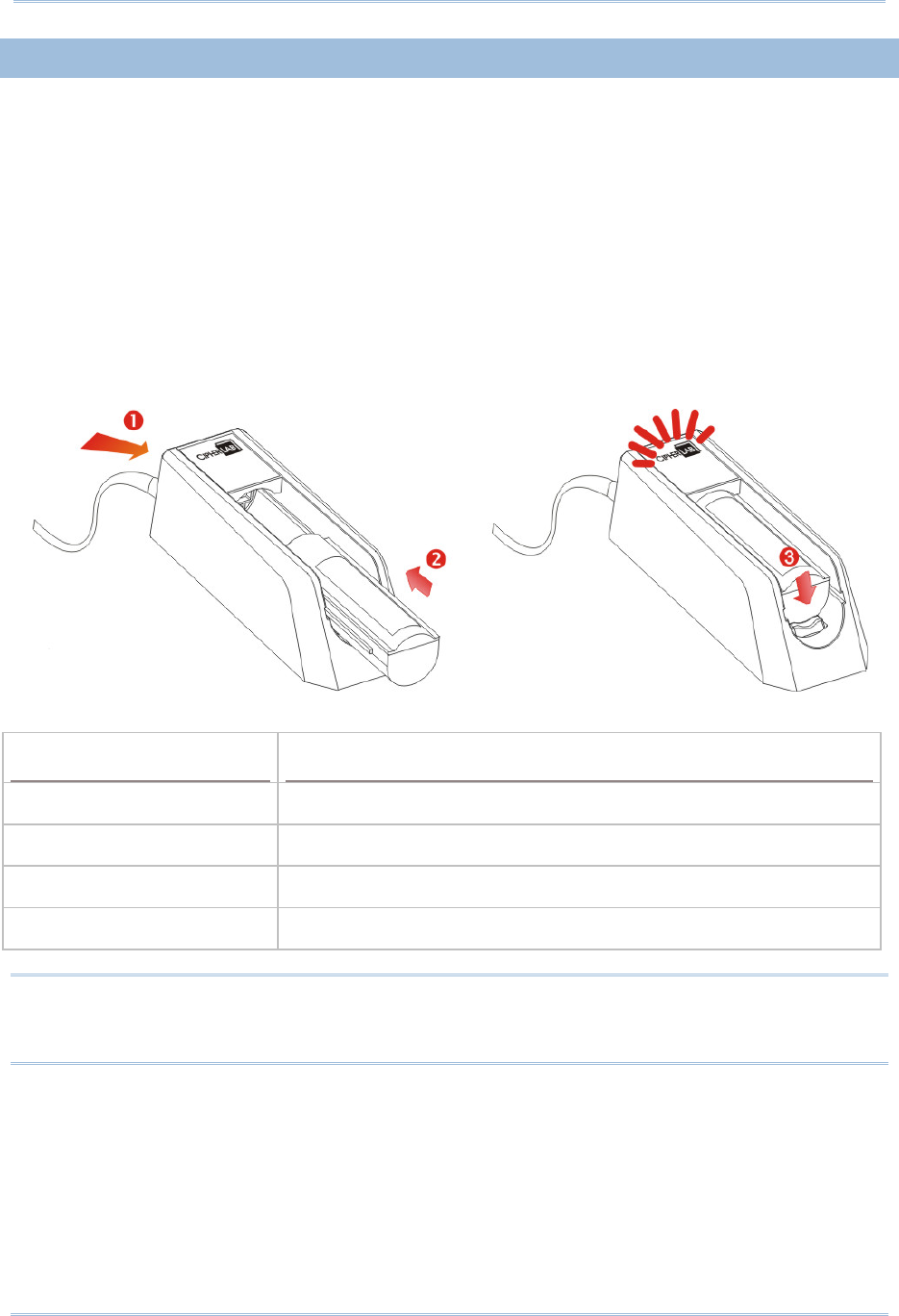
POWER ON RFID READER
Be sure the battery is fully charged before you power on the RFID Reader. Press the
trigger for 2 seconds to power on the RFID Reader. The reader will respond with a long
beep (high tone), and LED1 will become solid red for 1 second and go off.
Note: The LED2 will flash blue when you power on the RFID Reader successfully.
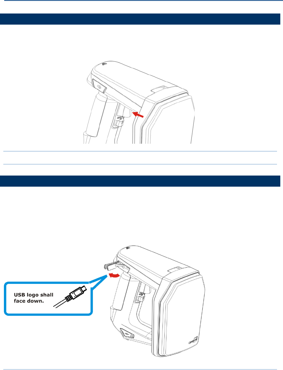
CONNECTING USB CABLE
1) The RFID Reader has a built-in USB port enabling its connection to host computers for
configuration and data transmission.
2) Remove the USB port cover.
3) Connect the USB communication cable to USB port. (USB logo shall face down)
4) Connect the other end of USB cable to the host computer.
QUICK START
8
1800 Series Handheld RFID Reader Reference Manual
ISSUING COMMANDS VIA USB CONNECTION
USB connection can be used for configuring the Reader and to upload data to host
computer. Below are the procedures to create a USB connection before using RFID
Reader.
USING HYPERTERMINAL
On the host computer:
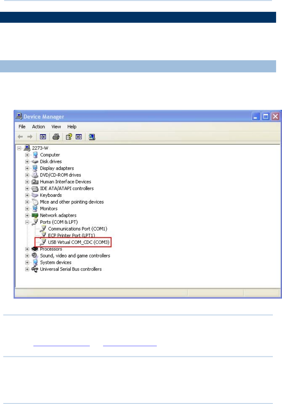
1) Go to the “Device Manager” on the host computer to confirm the used COM port. For
example below, the USB Virtual COM_CDC - COM3 is being used.
Note: By default the USB Interface type set on 1800 RFID Reader is Virtual COM CDC
(CDC and Silicon USB interfaces available). And users are supposed to install the
corresponding driver on host computer before beginning to use RFID Reader. Refer
to 2.1 USB Interface or 1.3.1.2 Functions used for selecting USB type during
operation.
9
Quick Start
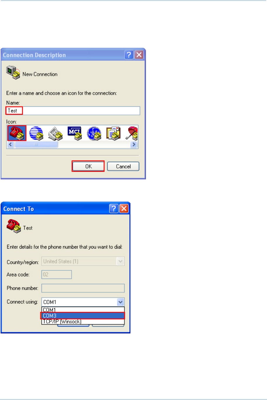
2) Use a terminal emulation program, e.g. HyperTerminal, to confirm the connection
between host computer and RFID Reader. Open the HyperTerminal on the host
computer.
3) Enter a name and choose an icon for the connection. Click “OK” to continue.
4) According to the information of Step 1, select the proper connected COM port, e.g.
COM3.
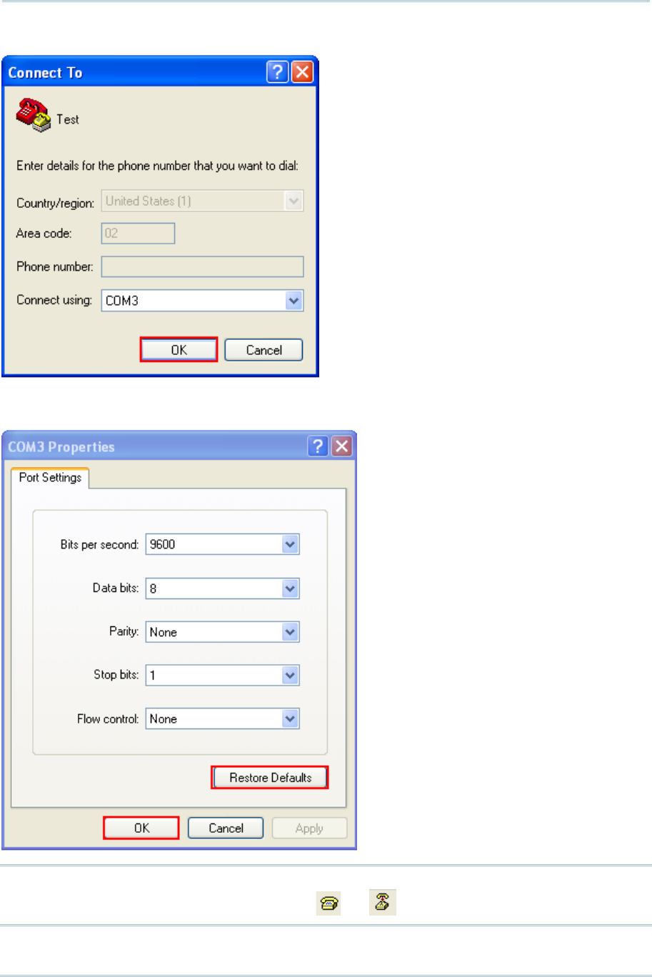
10
1800 Series Handheld RFID Reader Reference Manual
5) Click “OK”.
6) In the COM3 Properties window, you can click the “Restore Defaults” to use default
values for connection. Then, click “OK”.
Note: After finishing the COM Properties configuration, the connected icon on the
HyperTerminal will be changed from to automatically.
11
Quick Start
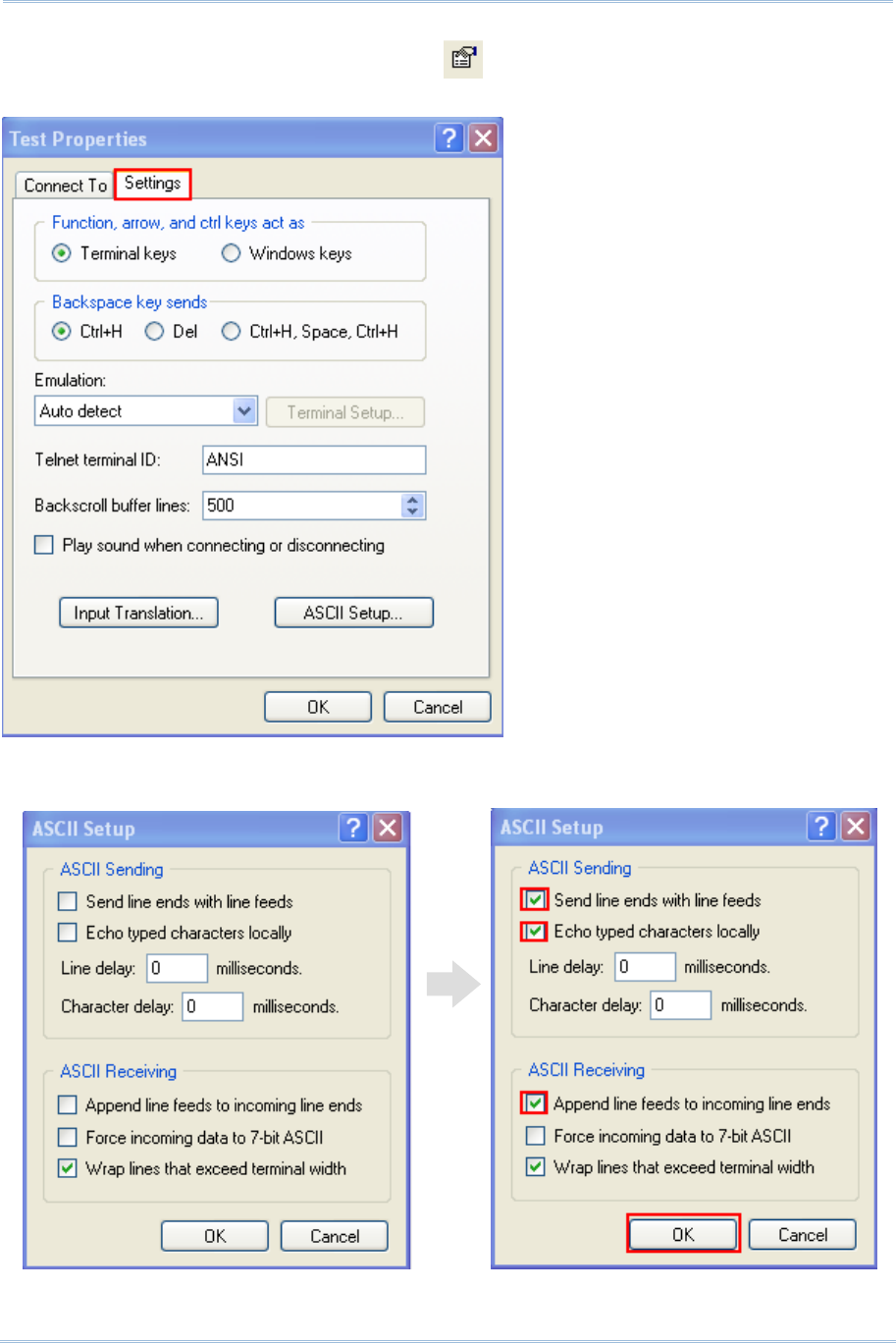
7) In the HyperTerminal window, click on the tool bar to open Properties
configuration window, see below. Click “Settings” tab.
8) Click [ASCII Setup] to open ASCII Setup window and some check boxes need to be
selected for normalized issuing commands, see below. Click “OK”.
12
1800 Series Handheld RFID Reader Reference Manual
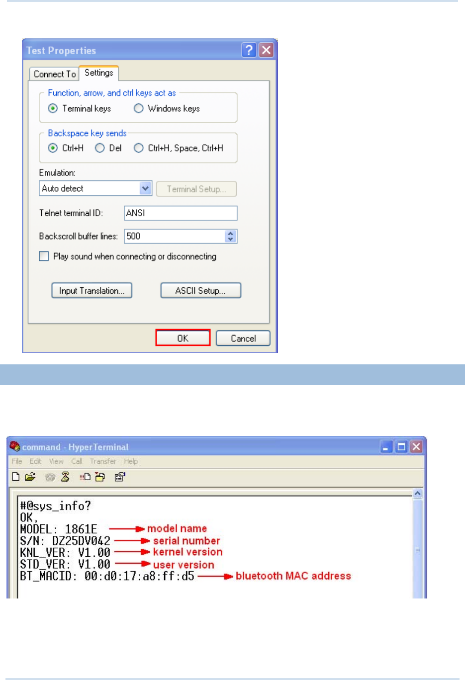
9) After finishing ASCII Setup, in the Properties configuration window, click “OK”.
CONFIRMING THE USB CONNECTION
Now, you can begin to issue commands between the host computer and RFID Reader.
For example, you can issue “#@sys_info?” command for testing. If the connection is
successful, the HyperTerminal will display the following response from the reader.


14
1800 Series Handheld RFID Reader Reference Manual
DEFAULT SETTINGS
SAVE USER SETTINGS AS DEFAULTS
For the RFID Reader to keep the customized settings as user defaults, you must issue
“#@sys_svusrtbl” command.
Note: After issuing the command, the current settings will be saved as user defaults.
Command:
#@sys_svusrtbl\r
Purpose Save User Defined Setting
Response OK\r
ERR,[code]\r
RESTORE USER/FACTORY DEFAULTS
For the RFID Reader to restore the User Defaults, which you have saved earlier, you
must issue the “#@sys_ldstbl=1” command. Alternatively, you can also issue the
“#@sys_ldstbl=0” command to restore Factory Default.
Command:
#@sys_ldstbl=[m]\r
Purpose Load Default Setting
Request #@sys_ldstbl=[m]\r
[m]: ‘0’ – Factory Default
‘1’ – User Default
Response OK\r
ERR,[code]\r
Note: Restoring factory defaults may reset any active Bluetooth® connections and erase
the MAC address information of the connected device.
15
Quick Start
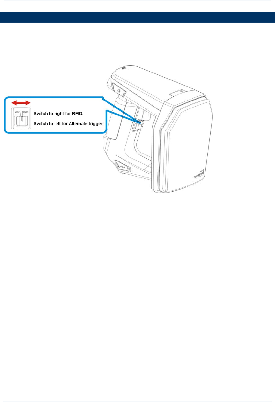
READER SWITCH
RFID Reader supports a switch that is used to toggle between RFID Reader and Alternate
trigger scan. Shift the switch to the right for RFID and left for Alternate trigger.
Make sure the reader switch is set to correct location based on RFID or Alternate mode.
For more Alternate mode information, please refer to Alternate Mode.
16
1800 Series Handheld RFID Reader Reference Manual
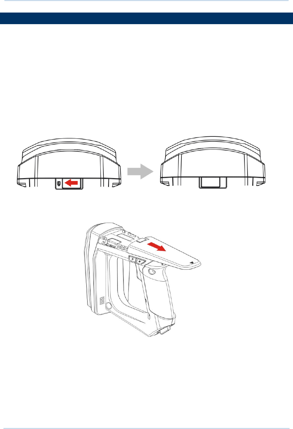
COMBINING WITH A MOBILE COMPUTER
If you wish to combine the RFID Reader with a mobile computer, please remove the
mounting plate cover and then install the mobile computer mount. Follow the steps below
to remove the mounting plate cover:
1) Place the RFID Reader on a flat and clean surface.
2) Slide the mounting plate cover latch to unlock position.
3) Slide the mounting plate cover smoothly out of the RFID reader.
4) Align the mobile computer mount, which may vary depending on the mobile computer
you plan to use, with the reader and slide along the guide slots of the reader.
5) Install the mobile computer in the mobile computer mount.
17
Quick Start
1800 CONFIGURATION
You can configure the RFID Reader by issuing commands or 1800Configuration Utility.
Serial Command:
You may run HyperTerminal.exe on the host computer to send commands to RFID
Reader via USB virtual COM or Bluetooth® SPP. The commands are not case sensitive.
Example:
#@sys_time?<CR>
Get the system time information.→
#@sys_time=[Y],[M],[D],[h],[m],[s]<CR>
Set the system time. →[Y],[M],[D],[h],[m],[s] are the parameters of system time.
Note: A Serial Command consists of Prefix, Text, and Suffix. The prefix consists of “#”
and “@”. “?” or “=” is specified to suffix. \r or <CR> is specified for the “Enter” of
your keyboard. As a normal command event, it will respond with “OK” or “ERR”.
About “ERR”, please refer to Status Code for more information.
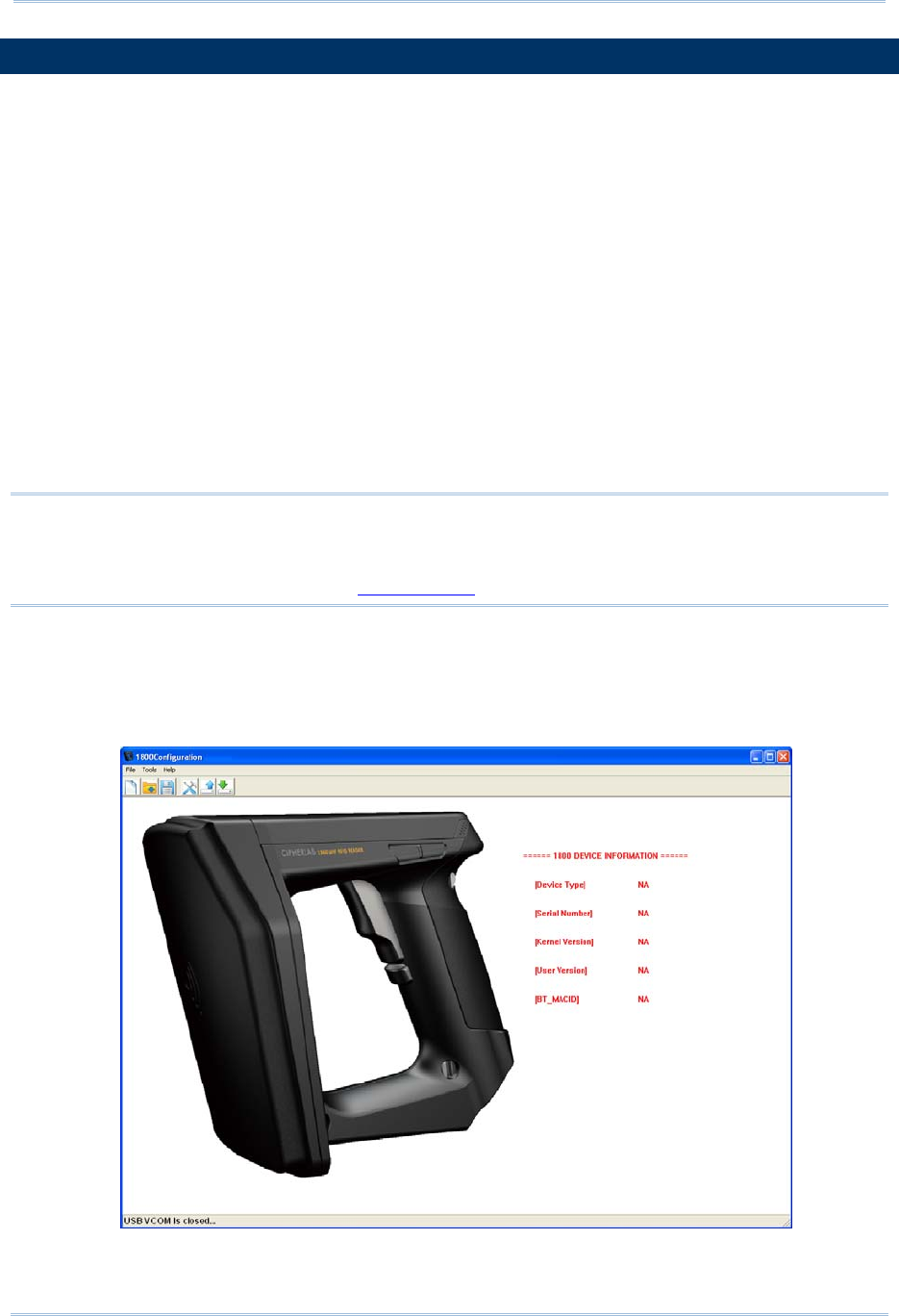
1800Configuration Utility:
CipherLab supports a Windows®-based Software Utility to allow you to configure RFID
Reader easily. For more information, please refer to 1800Configuration User Guide.

18
1800 Series Handheld RFID Reader Reference Manual

19
This chapter explains the features and usage of RFID Reader. Before configuring RFID
Reader, we will detail the information received when “#@sys_info?” command is issued.
Command:
#@sys_info?\r
Purpose Get System Information
Response OK,[m]\r[n]\r[o]\r[p]\r[Q]\r
[m]: string that indicates model name
“1861E” – Basic UHF type Europe Band
“1861U” – Basic UHF type US Band
[n]: string that indicates serial number
[o]: string that indicates kernel version
[p]: string that indicates user version
[q]: string that indicates BTMACID
ERR,[code]\r
Example:
Command
#@sys_info?
Response (s)
OK,
MODEL: 1861E →model name
S/N: DZ25DV042 →serial number
KNL_VER: V1.00 →kernel version
STD_VER: V1:00 →user version
BT_MACID: 00:d0:17:a8:ff:d5 →Bluetooth® MAC address
Chapter 1
UNDERSTANDING RFID READER

20
1800 Series Handheld RFID Reader Reference Manual
IN THIS CHAPTER
1.1 Power ...................................................................... 21
1.2 Memory.................................................................... 24
1.3 Function Key ............................................................. 31
1.4 LED Indicators........................................................... 37
1.5 Beeper ..................................................................... 40
1.6 Vibrator.................................................................... 44
1.7 RTC ......................................................................... 45
1.8 Event ....................................................................... 46

21
Chapter 1
Understandin
g
RFID Reader
1.1 POWER
RFID Reader is powered by a rechargeable 3.7V/2500mAh Li-ion battery pack, and it
takes approximately 4 hours to fully charge it via charger or adapter. During normal
operation, the RFID Reader can work for up to 10 hours.
Warning: The battery cover must be in position. If not, the RFID Reader cannot turn on.
For a new battery, make sure it is fully charged before you begin to use it.
Always prepare a spare battery, especially when you are working on a non-stop
operation.
1.1.1 POWER ON
After installing the battery, press the trigger for 2 seconds. The RFID Reader will respond
with a long beep (high tone), and LED1 will become solid red for 1 second and go off.
1.1.2 POWER OFF
The RFID Reader will stay active at power-on, which may be followed by a transition from
full CPU speed to low CPU speed (Power-Saving) to auto shutdown (Auto Power Off).
Auto Power Off (1~254 min.; 0= Disable): By default, it is set to automatically shut down
after idling 10 minutes. If this feature is not desired, set it to 0.
Command:
#@sys_tpoff?\r
Purpose Get the Delay Time of System Shutdown
Response OK,[m]\r (Default m= ‘10’)
[m]: ‘0’ ~ ‘254’ (Unit=minute)
ERR,[code]\r
#@sys_tpoff=[m]\r
Purpose Set the Delay Time of System Shutdown
Response OK\r
ERR,[code]\r

22
1800 Series Handheld RFID Reader Reference Manual
Press <F1>+<F2> keys for 3 seconds with two short beeps, high tone and then release
both keys to force the RFID Reader to shut down. Alternatively you can also issue
command on the host computer described below to power off the RFID Reader.
Command:
#@sys_off\r
Purpose System Shutdown
Response OK\r
ERR,[code]\r
1.1.3 POWER SAVING MODE
Power Saving (1~254 min.; 0= Disable): By default, it is set to idle at full-speed for 2
minutes before it enters power saving mode. If this feature is not desired, set it to 0.
Note: The Power Saving setting will not take effect when data is transmitting via
Bluetooth® HID or SPP.
Command:
#@sys_tps?\r
Purpose Get the Delay Time of Power Saving Mode
Response OK,[m]\r (Default m= ‘2’)
[m]: ‘0’ ~ ‘254’ (Unit=minute)
ERR,[code]\r
#@sys_tps=[m]\r
Purpose Set the Delay Time of Power Saving Mode
Response OK\r
ERR,[code]\r
Note: Power Saving will not take effect when one of the following conditions is met:
(1) RFID Reader is being configured by the 1800 Configuration Utility.
(2) The scanning mode is set to Test Mode.
(3) The setting value of Power Saving is greater than Auto Power Off.

23
Chapter 1
Understandin
g
RFID Reader
Issue “#@sys_kalive” command to keep system active for a further period of time. Each
time with this command issued, the delay time for system shutdown and power saving
mode will be reset.
Command:
#@sys_kalive\r
Purpose Keep the System Alive
Response OK\r
ERR,[code]\r
1.1.4 LOW BATTERY ALARM
By default, the battery alarm will beep when the battery charge gets low. In order to
prevent data loss, it is advised to replace the battery immediately when hearing two
short beeps (high tone).
Command:
#@sys_battery?\r
Purpose Get Remaining Capacity of Battery
Response OK,[m],[n]\r
[m]: remaining battery capacity. (e.g. 100%)
[n]: charging status
‘0’ – not charging
‘1’ – being charged
‘2’ – fully charged
ERR,[code]\r
#@sys_lbalarm?\r
Purpose Get Low Battery Alarm
Response OK,[m]\r (Default m= ‘1’)
[m]: ‘0’ – Disable
‘1’ – Enable
ERR,[code]\r
#@sys_lbalarm=[m]\r
Purpose Set Low Battery Alarm
Response OK\r
ERR,[code]\r

24
1800 Series Handheld RFID Reader Reference Manual
Warning: Using Bluetooth® connection will substantially reduce battery power.
Disable the Bluetooth® function when it is not in use.
1.2 MEMORY
Memory Mode
4MB flash for Memory Mode data access.
Transmit Buffer Memory
2KB buffer while getting out of range over a wireless personal area network (WPAN)
The RFID reader has 2 modes online through Bluetooth®, or memory mode where scans
are stored and transmitted at a later stage through USB.
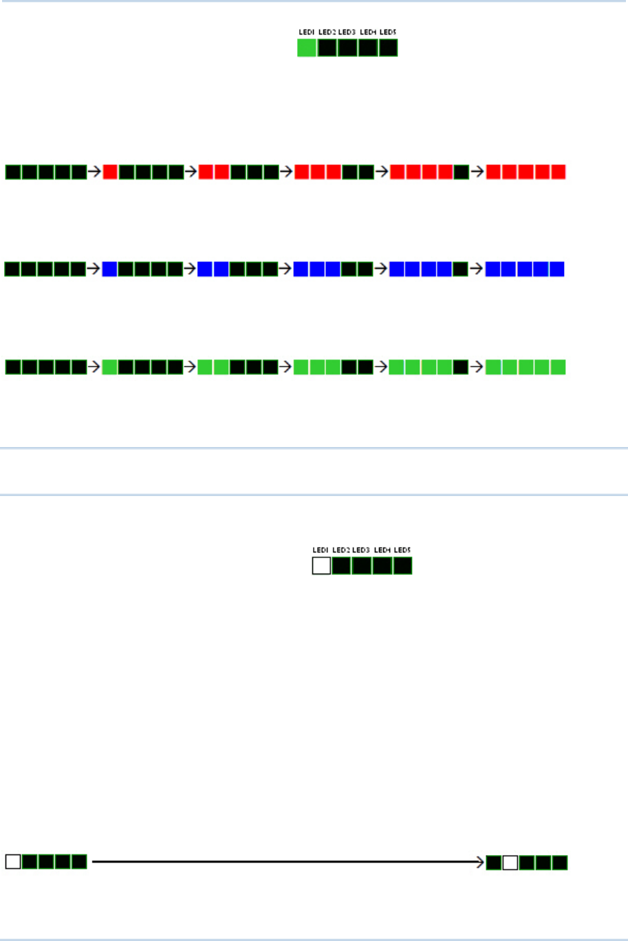
1.2.1 TRANSMIT BUFFER
By default, transmit buffer is enabled and used when the RFID Reader is out of range.
Upon reading a tag successfully within range, the RFID Reader responds with one short
beep (high tone) and LED3 indicator becomes solid green and goes off. When the reader
gets out of range, the transmit buffer is used to stored scanned tags until the buffer is
full or until its back within range.
When transmit buffer is enabled…
If the RFID Reader is out of range, it will respond with two short beeps, high-low tone, upon
reading a tag successfully.
When transmit buffer is full, the RFID Reader will respond with one long beep (low tone). You are
advised to get back within range.
When transmit buffer is disabled…
If the RFID Reader is out of range, it will respond with one long beep (low tone). You are advised
to get back within range.

25
Chapter 1
Understandin
g
RFID Reader
Command:
#@sys_txben?\r
Purpose Get Transmit Buffer Status
Response OK,[m],[n]\r
ERR,[code]\r
#@sys_txben=[m] {,[n]}\r
Purpose Enable Transmit Buffer
[m]: ‘0’ – Disable (default)
‘1’ – Enable
‘2’ – Enable passive transmit buffer
[n]: ‘0’ – Keep data until getting “clear buffer” command
‘1’ – Automatically clear the buffer after data sent (default)
[n] exists only when [m] is set to 2. When [m] is set to 0 or 1, [n] will be reset
to default.
Response OK\r
ERR,[code]\r
#@sys_txbdly?\r
Purpose Get Transmit Buffer Delay
Response OK,[m]\r
ERR,[code]\r
#@sys_txbdly=[m]\r
Purpose Set Transmit Buffer Delay
Request [m] Send TX Buffer Delay
‘0’ 0 (default)
‘1’ 250 ms
‘2’ 500 ms
‘3’ 1 sec
‘4’ 2 sec
‘5’ 3 sec
‘6’ 5 sec
‘7’ 8 sec
Response OK\r
ERR,[code]\r

26
1800 Series Handheld RFID Reader Reference Manual
#@sys_txbup\r
Purpose Inquire Data from Transmit Buffer
Response OK\r //command received
[m]\r //data string
EOT,[n]\r //End of Transmit. [n] indicates the total data count in buffer.
ERR,[code]\r
#@sys_txbclr\r
Purpose Clear Transmit Buffer
Response OK\r
ERR,[code]\r

27
Chapter 1
Understandin
g
RFID Reader
1.2.2 MEMORY MODE
The RFID Reader includes 4MB flash memory for data storage when the reader operates
in memory mode. When the RFID Reader gets into memory mode, the current
Bluetooth® connection with the host is disabled.
Warning: Bluetooth® connection is not available in the memory mode.
STATUS
Confirm the memory size by issuing “#@sys_memsize?” command.
Command:
#@sys_memen?\r
Purpose Get Memory Mode Status
Response OK,[m]\r (Default m= ‘0’)
[m]: ‘0’ – Disable
‘1’ – Enable
ERR,[code]\r
#@sys_memen=[m]\r
Purpose Set Memory Mode
Response OK\r
ERR,[code]\r
Note: You can also enter/exit memory mode by pressing function keys. Refer to 1.3.1.2
Functions.
#@sys_memsize?\r
Purpose Get Free Memory Size
Response OK,[m]\r (Max. 4072)
[m]: Free Memory Size string in KB
ERR,[code]\r

28
1800 Series Handheld RFID Reader Reference Manual
DATA DELAY
You may set a delay time between each data record while transmitting data back to the host
computer.
Command:
#@sys_memdly?\r
Purpose Get Data Transmission Delay
Response OK,[m]\r (Default m= ‘0’)
[m]: ‘0’~’7’
Data Transmission Delay
Value Delay
‘0’ 0 ms
‘1’ 250 ms
‘2’ 500 ms
‘3’ 1 sec
‘4’ 2 sec
‘5’ 3 sec
‘6’ 5 sec
‘7’ 8 sec
ERR,[code]\r
#@sys_memdly=[m]\r
Purpose Set Data Transmission Delay
Response OK\r
ERR,[code]\r

29
Chapter 1
Understandin
g
RFID Reader
SEND DATA
To transmit the data to the host immediately, use the following command “#@sys_memup”.
Command:
#@sys_memup\r
Purpose Upload Memory Data
Response OK\r //command received
[m]\r //data string
EOT,[n]\r //End of Transmit. [n] indicates the total data count.
ERR,[code]\r
CLEAR MEMORY
Even though data has been sent back to the host, the flash memory is still occupied with the
scanned data which can be uploaded repeatedly unless you erase the memory by issuing
“#@sys_memclr” command to clear memory.
Command:
#@sys_memclr\r
Purpose Clear Memory
Response OK\r
ERR,[code]\r

30
1800 Series Handheld RFID Reader Reference Manual
Example:
Command
#@sys_memsize? →get current memory size
Response (s)
OK, 4072
Command
#@sys_memen=1 →enter memory mode
Response (s)
OK
Command
#@sys_memdly=4 →set the delay time of data transmission to 2 sec.
Response (s)
OK
Command
#@sys_memup →upload memory data
Response (s)
1. 2012-04-18 30003430333130303132303030304221
2. 2012-04-18 30003430333130303132303030304221
3. 2012-04-18 30003430333130303132303030304221
OK
Command
#@sys_memclr →clear memory size
Response (s)
OK
] 2sec.→
] 2sec.→
31
Chapter 1
Understandin
g
RFID Reader
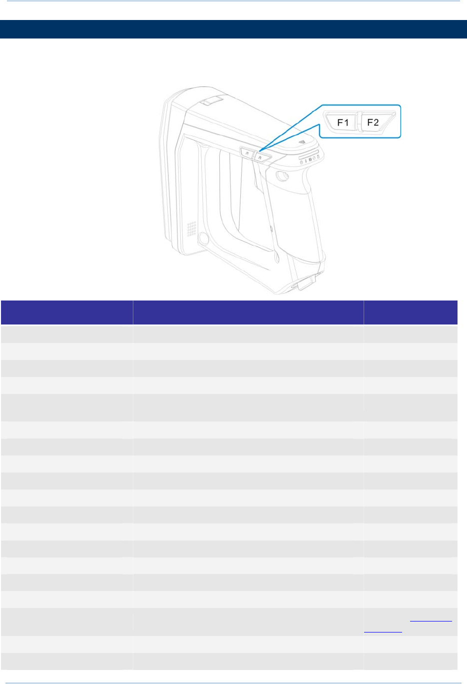
1.3 FUNCTION KEYS
The function keys serve as a modifier key, and the functionality of each key combination
is application-dependent.
Keys Action Mode
<Trigger> Scan Tag RFID
Select number 1~5 Bluetooth® Pairing
Send string Alternate
<F1> Execute special function RFID
Switch the LED status between power level, BT
signal level, data memory space level
RFID
Send string Alternate
<F2> Select special function RFID
Send string Alternate
Put selected number to PIN Code buffer Bluetooth® Pairing
<F1>+<F2> Power off the system RFID, Alternate
Switch among special command group RFID
Erase PIN Code Bluetooth® Pairing
<F1>+<Trigger> Select number 6~0 Bluetooth® Pairing
Send string Alternate
<F2>+<Trigger> Send PIN Code to paired BT device Bluetooth® Pairing
Send string Alternate
Firmware Upgrade Refer to Firmware
Upgrade
<F1>+<F2>+<Trigger>
Cancel the pairing Bluetooth® Pairing
Reader Switcher Used to switch the RFID and Alternate mode
32
1800 Series Handheld RFID Reader Reference Manual
1.3.1 RFID MODE
1.3.1.1 FUNCTION KEY FOR POWER OFF
Press <F1>+<F2> keys for 3 seconds with two short beeps, high tone and then release
both keys to power off the RFID Reader.
1.3.1.2 FUNCTIONS
Note: Press <F1>+<F2> to switch between Group1, Group2 or Group3. The 3 groups of
function key commands are only available in RFID mode. In Alternate mode, the
function keys are only used for keypad output strings.
33
Chapter 1
Understandin
g
RFID Reader
Group1 System Status (Green LED1):
Press <F1>+<F2> to enter Group1 with Green LED1. In the Group1, you can press
<F1> to switch among Battery Status, Bluetooth® Signal Quality, and Data Memory
Space. After idling for 3-seconds timeout, the LED status will return to normal mode.
Power Level (Red LED)
Battery Empty Full Battery
Bluetooth® Signal Strength (RSSI) (Blue LED)
Poor Very Good
Available Memory Capacity (Green LED)
Memory Full Memory Empty
Note: You must have an active Bluetooth® connection to display the Bluetooth® signal
strength.
Group2 RFID Assistance (White LED1):
Press <F1>+<F2> to switch to Group2 with White LED1. The Group2 includes two
defined commands (Command1 and 2). Press <F2> to switch between Command1 and
Command2; press <F1> to execute the command. The LED status will return to normal
mode when you idle for about 3 seconds during configuration.
Command1: Set Single or Multi-Tag Scan Mode. With F1 pressed, two beeps with
tones ascend from low to high.
(As serial commands: “#@rf_scan=6” or “#@rf_scan=9”)
Command2: Clear the tag list for Multi-Tag Scan Mode. With F1 pressed, two beeps
with tones ascend from low to high.
(As serial command: “#@rf_mtagcnt=”)
Press <F2> to switch between Command 1 and 2 (each press two beeps with tones
ascending from low to high).
Command1 Command2
34
1800 Series Handheld RFID Reader Reference Manual
Executing:
Function Key Operation LEDs Status
Command1 <F1>+<F2> <F→1: Executing>
Command2 <F1>+<F2> <F2> < F→→1: Executing>
Group3 Others (Yellow LED1):
Press <F1>+<F2> to switch to Group3 with Yellow LED1. The Group3 is defined to 4
commands. Press <F2> to switch among the Commands or press <F1> to execute the
command. The LED status will return to normal mode when you idle about 3 seconds
during configuration.
Command1: Enable/Disable memory mode.
(As serial command: “#@sys_memen=1/0” )
Command2: Clear data memory.
(As serial command: #@sys_memclr)
Command3: Select USB virtual COM driver (Switch between CDC and SiliconLab).
(As serial command: #@usb_type=127/128)
Note: By default, the value of the reader for USB Virtual COM driver is CDC (usb
type=127). Press <F1> one time upon command3 to switch to SiliconLab type if
you are using SiliconLab driver as a Virtual COM connection. Wrong VCOM type
selection will cause disconnection to the host.
Command4:
a. Breaks the current connection if Bluetooth® connection exists.
b. If there’s no Bluetooth® connection, resets the connection type to default –
SPP slave.
(depending on the Bluetooth® connection status, it is to run the serial command
“#@bt_disc” or “#@bt_reset”)
Press <F2> to switch between Command 1, 2, 3 and 4
Command1 Command2 Command3 Command4
Note: Except for function keys, you can also issue command to break or reset the
Bluetooth® connection. Refer to 3.3.1 Break a Connection and 3.3.2 Reset a
Connection.
35
Chapter 1
Understandin
g
RFID Reader
1.3.2 BLUETOOTH® PAIRING MODE
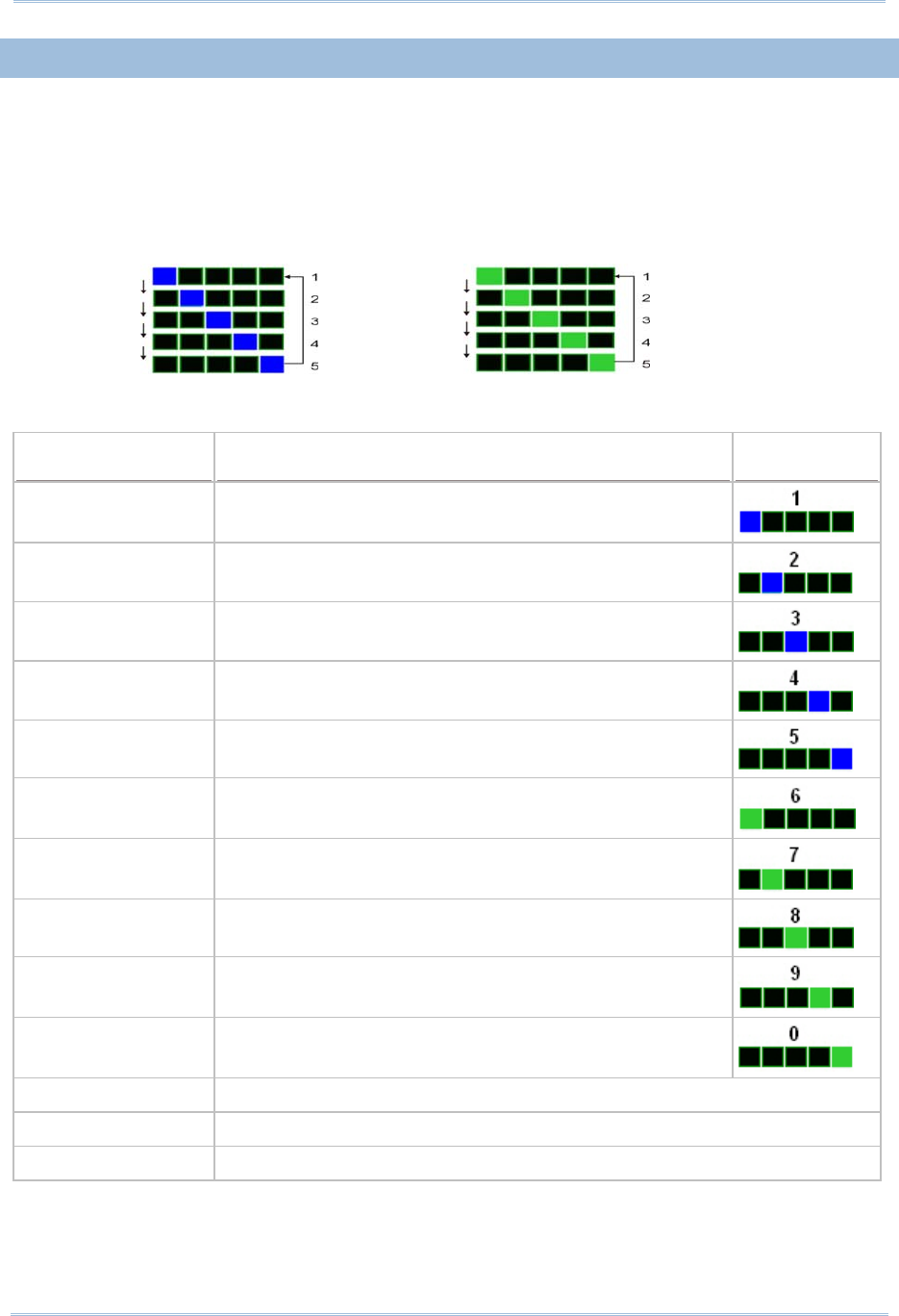
For Bluetooth® connection requiring PIN code input, you can use Function key and
<Trigger> combination to input numeric codes.
Various numeric input will show you different LED status illustrated below:
No.1~5 No.6~0
PIN CODE Input for Bluetooth® Pairing:
Number Input Key Operation LEDs Status
Number 1 <Trigger> once <F2> →
Number 2 <Trigger> twice <F2> →
Number 3 <Trigger> three times <F2> →
Number 4 <Trigger> four times <F2> →
Number 5 <Trigger> five times <F2> →
Number 6 <F1+Trigger> once <F2> →
Number 7 <F1+Trigger> twice <F2>→
Number 8 <F1+Trigger> three times <F2> →
Number 9 <F1+Trigger> four times <F2> →
Number 0 <F1+Trigger> five times <F2> →
Send PIN Code <F2>+<Trigger>
Erase the PIN Code <F1>+<F2>
Cancel the Pairing <F1>+<F2>+<Trigger>


37
Chapter 1
Understandin
g
RFID Reader
1.4 LED INDICATORS
The five LEDs on the RFID Reader are used to provide a feedback to users about the
behavior of the RFID Reader. For example, the LED1 becomes solid red and goes off
upon powering on.
The status of LED indicators may vary depending on working modes ─General, Function
Key and Bluetooth® Pairing Modes.
1.4.1 GENERAL MODE
In General mode LEDs show you normal system status without any advanced
configuration.
LED Color Status Description
Red On-Off Power on, with one long beeps (high tone,
LED1 on for 1 second and then off.)
Red On Charging Fail
Power Off (With F1+F2 pressed to
power off, it remains solid red until both
of the function keys are released)
Red Flashing Charging (On/Off ratio 0.5s:0.5s)
LED1-Power
Green Flashing Charging Done (On/Off ratio 0.5s:0.5s)
On/Off ratio 0.5s:0.5s indicates the RFID
Reader is waiting for connection
On/Off ratio 0.1s:0.1s indicates the RFID
Reader receives a PIN code request from
host (flashing more quickly than waiting
connection)
LED2-Bluetooth®
Communication
Blue Flashing
On/Off ratio 0.02s:3s indicates the RFID
Reader has established a Bluetooth®
connection successfully.
LED3-RFID Tag Access
Green On-Off Good Read/Write with one short beeps (high
tone). The pitch and duration are
programmable.
LED4-Data
Transmission
Green Flashing Indicate the data is transmitted between
RFID Reader and host. The speed of
flashing varies with data rate.
Green Flashing Flashing ((On/Off ratio 0.02s:3s) indicates
Free memory size > 10%
** Only for memory mode
LED5-Memory Status
Red Flashing Flashing (On/Off ratio 0.02s:3s) indicates
memory under 10%
** Only for memory mode

38
1800 Series Handheld RFID Reader Reference Manual
Note: You can configure the good read LED3 status (disable/enable) and duration
(ranging from 1 to 254 in units of 10 milliseconds) by command. When you set the
LED3 feedback as disable, the LED3 will always be off.
GOOD READ LED STATUS
You may configure the LED3 status for a feedback about good read.
Command:
#@sys_leden?\r
Purpose Get Good Read LED Status
Response OK,[m]\r (Default m= ‘1’)
[m]: ‘0’ – Disable
‘1’ – Enable
ERR,[code]\r
#@sys_leden=[m]\r
Purpose Set LED Good Read Status
Response OK\r
ERR,[code]\r
GOOD READ LED DURATION
For a good read for LED3, you may configure the duration time.
Command:
#@sys_leddu?\r
Purpose Get Good Read LED Duration
Response OK,[m]\r (Default m= ‘4’)
[m]: Duration=‘1’ ~ ‘254’
ERR,[code]\r
#@sys_leddu=[m]\r
Purpose Set LED Duration
Response OK\r
ERR,[code]\r

39
Chapter 1
Understandin
g
RFID Reader
1.4.2 FUNCTION KEY MODE
LEDs indicate the corresponding functions according to function key combinations. Please
refer to 1.3.1.2 Function.
1.4.3 BLUETOOTH® PAIRING MODE
LEDs indicate the number which are input by function keys during Bluetooth® pairing.
Please refer to 1.3.2 Bluetooth® Pairing Mode.

40
1800 Series Handheld RFID Reader Reference Manual
1.5 BEEPER
The RFID Reader has a beeper to provide feedback in various operating conditions.
Function Beeping
Power on, with Red LED1 on (1 second) and off One long beep, high tone
Good read, with Green LED3 on-off
Enter PIN code
Switch among status LED mode
Programmable, default to 4KHz
One short beep, high tone
Select PIN code
Multi_Tag Mode: Get a repeated tag
(Default: Disable)
One short beep, low tone
Fail to send data or response
- Transmit buffer full
- Transmit buffer is disabled while Bluetooth®
is not connected or out of range.
Command fail
One long beep, low tone
Data saved to buffer when transmit buffer is
enabled and the RFID Reader is out of range
Memory Mode: Memory full
Two short beeps, high-low tone
Command success
Send PIN code
Running out of transmit buffer
Two short beeps, low-high tone
Low battery alarm
Clear PIN code
Power off
Two short beeps, high tone
Bluetooth® connection is established
Bluetooth® connection is resumed, with LED2
flashing blue
Three short beeps, tone ascending from
low to high
Bluetooth® connection out of range or suspended
Three short beeps, tone ascending from
high to low
Multi_Tag Mode: Tag list is full (scan session
completes)
(Default: Disable)
Six short beeps,
low-mid-high-low-mid-high
Low voltage (under 5%) with warning
continual beeps
The battery is removed during charging
Continual beeps
When the battery voltage is under 5%, the reader will beep continuously. We suggest it
is better to charge the battery immediately before the RFID Reader is powered off. You
can get the voltage information by issuing “sys_battery?” command.

41
Chapter
1
Understandin
g
RFID Reader
The commands below describe the beeper related configurations:
VOLUME
There are four volume levels defined to beeping setting.
Command:
#@sys_bpvol?\r
Purpose Get Beeper Volume
Response OK,[m]\r (Default m= ‘High’)
[m]: Volume
‘0’ Mute
‘1’ Low
‘2’ Medium
‘3’ High
ERR,[code]\r
#@sys_bpvol=[m]\r
Purpose Set Beeper Volume
Response OK\r
ERR,[code]\r
COMMAND BEEP
By default, this function is disabled.
Command:
#@sys_cmdbp?\r
Purpose Get Status of Command Indicating Beep
Response OK,[m]\r (Default m= ‘0’)
[m]: ‘0’ – Disable
‘1’ – Enable
ERR,[code]\r
#@sys_cmdbp=[m]\r
Purpose Set Command indicating Beep
Response OK\r
ERR,[code]\r

42
1800 Series Handheld RFID Reader Reference Manual
GOOD READ
You have to enable the beeping function when you want to get audio feedback from RFID Reader.
Command:
#@sys_grdbp?\r
Purpose Get Status of Good-Read Beep
Response OK,[m]\r (Default m= ‘1’)
[m]: ‘0’ – Disable
‘1’ – Enable
ERR,[code]\r
#@sys_grdbp=[m]\r
Purpose Set Status of Good-Read Beep
Response OK\r
ERR,[code]\r
FREQUENCY
By default, the frequency for a beeper is configured to 4KHz. This function is available when
Good-Read beep is enabled.
Command:
#@sys_grdbf?\r
Purpose Get Beeper Frequency
Response OK,[m]\r (Default m= ‘1’)
[m]: Frequency
‘0’ 8 kHz
‘1’ 4 kHz
‘2’ 2 kHz
‘3’ 1 kHz
ERR,[code]\r
#@sys_grdbf=[m]\r
Purpose Set Beeper Frequency
Response OK\r
ERR,[code]\r

43
Chapter 1
Understandin
g
RFID Reader
DURATION
You can configure the beeping duration to shortest, short, longer or longest. This function is
available when Good-Read beep is enabled.
Command:
#@sys_grdbdu?\r
Purpose Get Beeper Duration
Response OK,[m]\r (Default m= ‘Shortest’)
[m]: Duration
‘0’ Shortest
‘1’ Short
‘2’ Longer
‘3’ Longest
ERR,[code]\r
#@sys_grdbdu=[m]\r
Purpose Set Beeper Duration
Response OK\r
ERR,[code]\r
Note: When you set the volume of beeper to mute, there will be no audio feedback.

44
1800 Series Handheld RFID Reader Reference Manual
1.6 VIBRATOR
The RFID Reader has a built-in vibrator, which can be issued command for feedback. This
can be helpful when working in noisy environments.
For good read/write, the vibrator will vibrate for 1 second then stop. The vibration and
duration are programmable.
STATUS
RFID Reader supports a vibration option that you can enable/disable by issuing “#@sys_viben=”
command.
Command:
#@sys_viben?\r
Purpose Get Vibrator Status
Response OK,[m]\r (Default m= ‘0’)
[m]: ‘0’ – Disable
‘1’ – Enable
ERR,[code]\r
#@sys_viben=[m]\r
Purpose Set Vibrator Status
Response OK\r
ERR,[code]\r
DURATION
By default, a good read vibration stays on for 1 second. Specify a value, ranging from 1 to 254 in
units of 100 milliseconds.
Command:
#@sys_vibdu?\r
Purpose Get Vibrator Duration
Response OK,[m]\r (Default m= ‘10’)
[m]: Duration=‘1’ ~ ‘254’
ERR,[code]\r

45
Chapter 1
Understandin
g
RFID Reader
#@sys_vibdu=[m]\r
Purpose Set Vibrator Duration
Response OK\r
ERR,[code]\r
1.7 RTC
RFID Reader supports a Real Time Clock to keep track of the current time.
Command:
#@sys_time?\r
Purpose Get System Clock
Response OK,[Y],[M],[D],[h],[m],[s]\r
[Y]: ‘00’ ~ ‘99’
[M]: ‘01’ ~ ‘12’
[D]: ‘01’ ~ ‘31’
[h]: ‘00’ ~ ‘23’
[m]: ‘00’ ~ ‘59’
[s]: ‘00’ ~ ‘59’
ERR,[code]\r
#@sys_time=[Y],[M],[D],[h],[m],[s]\r
Purpose Set System Clock
Response OK\r
ERR,[code]\r
Example:
Command
#@sys_time? →get current system time
Response (s)
OK,12,05,10,10,36,05 →date=2012/5/10, time=10:36 05
Command
#@sys_time=12,06,20,12,50,00 →set system date and time to 2012/6/20 12:50 00
Response (s)
OK

46
1800 Series Handheld RFID Reader Reference Manual
1.8 EVENT
Users can retrieve the current event settings and set them by purpose.
Command:
#@sys_evt?\r
Purpose Get Current Event Settings
Response OK,[m],[n]\r
m: The event setting is shown in 4-digit hexadecimal. Refer to the Event table
below.
n: ‘0’ – Disable (default)
‘1’ – Enable that events can be sent via USB if BT is not connected.
Bit Default Meaning
0 1 System will enter PS mode after this event.
1 1 System will shut down after this event.
2 1 Bluetooth will be disconnected after this event.
3 1
System setting is changed (by command via USB or FN key),
which is indicated by sending the Group Code and Command
Code in the Event packet.
4 0
Low Battery Alarm. 1800 sends this event every 30 seconds
if battery voltage is lower than 3.6V.
5 1 Mode switching between Alternate and RFID.
6 1 RFID failure (initial failure or no response during operating)
7 0 No tag is found when scan session times out in single mode
8 0
scan session completes in multi-tag mode
(new tag amount is equal to multi-tag counter)
9 0 Memory Mode/BT Mode switched
15~10 0 Reserved
ERR,[code]\r
Remark For example, Event code 001C (0000 0000 0001 1100) means “Low Battery” alarm,
“System Setting Changed” and “Bluetooth Will Be Disconnected” events occur.
#@sys_evt=[m]{,[n]}\r
Purpose Set Event Settings
Response OK\r
ERR,[code]\r
#@evt[m]{,[n]}\r
Response m: event code
n: command code which appears only when bit 3 of the event code is set.

47
Follow the sections below for output interfaces supported to establish USB and WPAN
connection with RFID Reader. Refer to the table as below:
1800 Communication Interface:
Interface Configuration RFID Data Out
Upload Memory Data
SPP Slave v v v
SPP Master v v v
HID v
3610 Virtual COM v v v
Bluetooth®
3610 HID v
USB Virtual COM
Windows CDC
Driver/SiliconLab Driver
v V (*) v
Note: ‘*’ means that RFID data can be output via USB Virtual COM only when users have
carried out the “#@dat_2usb=1” command. Please refer to 5.4 Output EPC Data via USB
Virtual COM.
IN THIS CHAPTER
2.1 USB Interface .......................................................... 48
2.2 Bluetooth® Connection Type........................................ 49
2.3 Bluetooth® SPP Slave ................................................. 50
2.4 Bluetooth® SPP Master ............................................... 50
2.5 Bluetooth® HID ......................................................... 51
2.6 USB VCOM and HID via 3610....................................... 61
Note: By default, the output interface is set to “SPP Slave”.
Chapter 2
COMMUNICATION INTERFACE

48
1800 Series Handheld RFID Reader Reference Manual
2.1 USB INTERFACE
Create a connection between RFID Reader and host computer; you have to select the
available USB interface type by the “#@usb_type=” command. You can also use the
function keys to switch between the USB interface types, refer to 1.3.1.2 Functions.
Command:
#@usb_type?\r
Purpose Get USB Interface Type
Response OK,[m]\r (Default m=‘127’)
[m]: USB Type
‘127’ – Virtual COM CDC
‘128’ – Virtual COM (Silicon Lab driver)
ERR,[code]\r
#@usb_type=[m]\r
Purpose Set USB Interface
Response OK\r
ERR,[code]\r

49
Chapter 2
Communication Interface
2.2 BLUETOOTH® CONNECTION TYPE
1800 RFID reader is capable of various Bluetooth® connection for different target
requirements. By default, the connection type is configured to “SPP Slave”.
Command:
#@bt_type?\r
Purpose Get Bluetooth® Interface Type
Response OK,[m]\r (Default m= ’0’)
[m]: Bluetooth® TYPE
Bluetooth® Type Description Read only / R/W
‘0’ SPP Slave R/W
‘3’ SPP Master R/W
‘5’ HID R/W
‘6’ 3610 Read only
ERR,[code]\r
#@bt_type=[m]\r
Purpose Set Bluetooth® Interface Type
Response OK\r
ERR,[code]\r

50
1800 Series Handheld RFID Reader Reference Manual
2.3 BLUETOOTH® SPP SLAVE
For Bluetooth® SPP Slave, issue the “#@bt_type=” to parameter ‘0’ for output interface.
Then, refer to Setting Up a WPAN Connection for related connection settings. By default,
RFID Reader connection type is configured to “SPP Slave”.
Example:
Command
#@bt_type? →get current Bluetooth® type
Response (s)
OK,0 →default Bluetooth® type is ‘0’ for SPP Slave
Command
#@bt_type=0 →set Bluetooth® type to SPP Slave
Response (s)
OK

51
Chapter 2
Communication Interface
2.4 BLUETOOTH® SPP MASTER
As a SPP master device, RFID Reader will be able to resume connection with the host
computer upon powering on again, as long as the host application is running. If RFID
Reader fails to resume connection, it will try every 5 seconds to re-connect to the host
computer unless you issue the “#@bt_reset” or “#@sys_ldstbl=” command.
For Bluetooth® SPP Master Connection, refer to 3.1.4 Bluetooth® SPP Master.
Note: In SPP Master Mode, RFID Reader has to connect within the specified period of time
(2 minutes by default). During the connection, the RFID Reader will enter Power
Saving Mode. It will automatically power off when the Auto Shutdown time is
reached. Refer to 1.1 Power.
2.4.1 ACTIVATE BLUETOOTH® SPP MASTER MODE
How to connect with the target machine?
Two parameters are necessary using “#@bt_target=” command for SPP Master connection. One is
to configure connection type as SPP Master; the other is MAC ID of the target machine.
Command:
#@bt_target?\r
Purpose Get Bluetooth® Target Machine
Response OK,[m],[n]\r
[m]: Bluetooth® Type, ‘0’ – SPP Master, ‘1’ – 3610
[n]: MACID of target Machine or S/N of 3610
ERR,[code]\r
#@bt_target=[m],[n]\r
Purpose Set Bluetooth® Target Machine
Response OK
ERR,[code]
Exit SPP Master Mode
To stop such re-connection, you can issue the “#@bt_reset” command so that the current
connection record (= MAC ID) will be cleared. Connection type will also be restored to default (SPP
Slave). Go through the whole process in Setting Up a WPAN Connection to establish a new WPAN
connection.

52
1800 Series Handheld RFID Reader Reference Manual
2.5 BLUETOOTH® HID
For Bluetooth® HID connection, issue the “#@bt_type=” command with parameter ‘5’.
Refer to 1Using HyperTerminal for related connection settings. To capture the data, run
any text editor on host computer and the scanned data will be transmitted to the host
computer.
HID Settings Defaults
Keyboard Type PCAT (US)
Alphabets Layout Normal
Numeric Layout Normal
Capital Lock Type Normal
Capital Lock State Off
Alphabets Transmission Case-sensitive
Numeric Transmission Alphanumeric keypad
Inter-Character Delay 0 (ms)
2.5.1 ACTIVATE BLUETOOTH® HID & SELECT KEYBOARD TYPE
When Bluetooth® HID interface is activated, you will have to select a keyboard type to
complete this setting. By default, Bluetooth® HID is activated with PCAT (US) type on the
RFID Reader.
Bluetooth® HID
The following keyboard types are supported —
No. Keyboard Type No.
Keyboard Type
64 PCAT (US) (Default) 71 PCAT (Belgium)
65 PCAT (French) 72 PCAT (Spanish)
66 PCAT (German) 73 PCAT (Portuguese)
67 PCAT (Italy) 74 PS55 A01-2 (Japanese)
68 PCAT (Swedish) 75 Reserved
69 PCAT (Norwegian) 76 PCAT (Turkish)
70 PCAT (UK) 77 PCAT (Hungarian)

53
Chapter 2
Communication Interface
Command:
#@bt_hididx?\r
Purpose Get Bluetooth® HID Parameter Index
Response OK,[m]\r
[m]: Parameter Index
[m] Description Valid Parameters
‘0’ HID KBD Type ‘64’~ ‘77’ (Default m=‘64’)
‘3’ Inter-function Delay ‘0’ ~ ‘254’ (Default m=‘0’)
‘4’ Inter-character Delay ‘0’ ~ ‘254’ (Default m=‘0’)
‘5’ Caps Lock State ‘0’ – OFF (Default)
‘1’ – ON
‘2’ – Auto
‘7’ Alphabets Transmission ‘0’ – Case Sensitive (Default)
‘1’ – Ignore Case
‘8’ Digits Transmission ‘0’ – Alpha Numeric Keypad (Default)
‘1’– Numeric Keypad
‘9’ Digits Position ‘0’ – Normal (Default)
‘1’– Lower Row
‘2’– Upper Row
‘10’ Keyboard Layout ‘0’ – Normal (Default)
‘1’ – AZERTY
‘2’ – QWERTZ
‘12’ HID Character Transmit Mode
‘0’ – Batch Processing (Default)
‘1’ – By Character
ERR,[code]\r
#@bt_hididx=[m]\r
Purpose Set Bluetooth® HID Parameter Index
Response OK\r\r
ERR,[code]

54
1800 Series Handheld RFID Reader Reference Manual
#@bt_hidpr?\r
Purpose Get Bluetooth® HID Parameter
Response OK,[m]\r
[m]: Parameter
ERR,[code]\r
#@bt_hidpr=[m]\r
Purpose Set Bluetooth® HID Parameter
Response OK\r
ERR,[code]\r
Example:
Command
#@bt_type=5 →change connected interface to BT HID
Response (s)
OK
Command
#@bt_hididx=0 →enter HID KBD type configuration
Response (s)
OK
Command
#@bt_hidpr=64 →set PCAT (US) for KBD type
Response (s)
OK

55
Chapter 2
Communication Interface
2.5.2 KEYBOARD SETTINGS
Alphabets Layout
Numeric Layout
Capital Lock Setting
Alphabets Transmission
Numeric Transmission
ALPHABETS LAYOUT
By default, the alphabets layout is set to normal mode, also known as the standard English layout.
Select French or German keyboard layout if necessary. The RFID Reader will make adjustments
when sending the "A", "Q", "W", "Z", "Y", and "M" characters according to this setting.
Options Parameter Description
Normal (Default) ‘0’ US keyboard.
AZERTY ‘1’ French keyboard.
QWERTZ ‘2’ German keyboard.
Note: This setting only works when the keyboard type selected is US keyboard, such as
PCAT (US). The Alphabets Layout and Numeric Layout setting must match your
keyboard.
56
1800 Series Handheld RFID Reader Reference Manual
US KEYBOARD STYLE – NORMAL
QWERTY layout, which is normally used in western countries.
Select “Lower Row” for the “Numeric Layout” setting for the upper row is for special
characters.
FRENCH KEYBOARD STYLE – AZERTY
French layout; see below for French Keyboard Style.
Select “Upper Row” for the “Numeric Layout” setting for the lower row is for special
characters.
GERMAN KEYBOARD LAYOUT – QWERTZ
German layout; see below for German Keyboard Style.
Select “Lower Row” for the “Numeric Layout” setting for the upper row is for special
characters.

57
Chapter 2
Communication Interface
NUMERIC LAYOUT
Select a proper layout that matches the alphabets layout. The RFID Reader will make adjustments
according to this setting.
Options Parameter Description
Normal (Default) ‘0’ Depend on the [Shift] key or [Shift Lock] setting.
Lower Row ‘1’ For QWERTY or QWERTZ keyboard.
Upper Row ‘2’ For AZERTY keyboard.
Note: This setting is to be used with the Character Substitution setting when support to
certain keyboard types (languages) is unavailable but required.
CAPITAL LOCK SETTING
In order to send the alphabets with correct case, the RFID Reader needs to know the status of
Caps Lock on the keyboard. Incorrect settings may result in reversed case of the alphabets being
transmitted.
Options Parameter Description
Capital Lock OFF
(Default)
‘0’ Assuming that the status of Caps Lock on the keyboard is
OFF, transmitted characters are exactly the same as in the
tag (when "case-sensitive" is selected for Alphabets
Transmission).
Capital Lock ON ‘1’ Assuming that the status of Caps Lock on the keyboard is
ON, transmitted characters are exactly the same as in the
tag (when "case-sensitive" is selected for Alphabets
Transmission).
Refer to the Capital Lock Type above.
Auto Detection ‘2’ The RFID Reader will
automatically detect the status of Caps
Lock on the keyboard before data is transmitted; transmitted
characters are exactly the same as in the tag (when
"case-sensitive" is selected for Alphabets Transmission).

58
1800 Series Handheld RFID Reader Reference Manual
ALPHABETS TRANSMISSION
By default, the alphabets transmission is case-sensitive, meaning that the alphabets will be
transmitted according to their original case, the status of Caps Lock on the keyboard, as well as the
Capital Lock setting. Select [Ignore Case] to have alphabets transmitted according to the status of
Caps Lock on the keyboard only.
Options Parameter Description
Case Sensitive
(Default)
‘0’ Alphabets will be transmitted according to the original case.
Ignore Case ‘1’ Alphabets will be transmitted according to the status of Caps
Lock on the keyboard only.

59
Chapter 2
Communication Interface
NUMERIC TRANSMISSION
By default, the alphanumeric keypad is used for transmitting numeric. Select “Numeric Keypad” if
you wish to use the numeric keypad.
Options Parameter Description
Alphanumeric
Keypad (Default)
‘0’ Alphanumeric Keypad will be used for transmitting numeric.
Numeric Keypad ‘1’ Numeric Keypad will be used for transmitting numeric.

60
1800 Series Handheld RFID Reader Reference Manual
2.5.3 INTER-CHARACTER DELAY
By default, the inter-character delay is set to zero. Specify a value, ranging from 0 to 254
in units of millisecond, to match the computer response time of the keyboard interface.
Such delay time is inserted between every character being transmitted. The longer the
delay time is, the slower the transmission speed will be.
Options Parameter Description
‘0’ (Default) ‘0’~‘254’ The range is from 0 to 254 in units of millisecond.
2.5.4 INTER-FUNCTION DELAY
By default, the inter-function delay is set to zero. Specify a value, ranging from 0 to 254
in units of milliseconds, to match the computer response time of the keyboard interface.
Such delay time is inserted between every function code (0x01 ~ 0x1F) being transmitted.
The longer the delay time is, the slower the transmission speed will be.
Options Parameter Description
‘0’ (Default) ‘0’~‘254’ The range is from 0 to 254 in units of millisecond.
2.5.5 HID CHARACTER TRANSMIT MODE
By default, HID interface sends data to the host in batch. You may configure the RFID
Reader to “By Character” to process data one character at a time.
Options Parameter Description
Batch Processing
(Default)
‘0’ Process data by Batch.
By Character ‘1’ Process data by Character
Note: “By Character” transmit mode is required when working with iPhone or iPad.

61
Chapter 2
Communication Interface
2.6 USB VCOM AND HID VIA 3610
Note: If you are using USB VCOM for the first time, you must install its driver from the
CD-ROM. Driver version 5.4 or later is required. Please remove older versions!
Refer to 2.1 USB Interface.
For USB VCOM and HID via 3610, connect 3610 to the USB port of host computer, and
then connect RFID Reader to 3610 via Bluetooth®. Before the Bluetooth® connection
between 1800 and 3610 is able to be established, users have to connect a USB cable
between them to tell 1800 the information about 3610 via the “bt_target” command.
To capture the data, run any text editor on host computer. The scanned data will be
transmitted to the host computer.
How to connect with the 3610?
Two parameters are necessary using “#@bt_target” command to make a connection with 3610.
One is to configure connect type as 3610; and the other is serial No. of the target machine.
Command:
#@bt_target?\r
Purpose Get Bluetooth® Target Machine
Response OK,[m],[n]\r
[m]: Bluetooth® Type, ‘0’ – SPP Master, ‘1’ – 3610
[n]: MACID of target Machine or S/N of 3610
ERR,[code]\r
#@bt_target=[m],[N]\r
Purpose Set Bluetooth® Target Machine
Response OK\r
ERR,[code]\r
Example:
Command
#@bt_target=1,BS9001346 →set target to 3610 with S/N:BS9001346
Response (s)
OK

62
1800 Series Handheld RFID Reader Reference Manual
HID Settings Defaults
Keyboard Type PCAT (US)
Alphabets Layout Normal
Numeric Layout Normal
Capital Lock Type Normal
Capital Lock State Off
Alphabets Transmission Case-sensitive
Numeric Transmission Alphanumeric keypad
Inter-Character Delay 0 (ms)
2.6.1 ACTIVATE USB VCOM AND HID & SELECT KEYBOARD TYPE
When USB VCOM and HID via 3610 interface is activated, you have to select a keyboard
type from parameters ‘097’ to ‘110’ so that you can complete this setting. Parameter
‘096’ is for USB VCOM via 3610 connection.
USB VCOM and HID via 3610 TYPE
The following keyboard types are supported —
No. Keyboard Type No.
Keyboard Type
096 USB VCOM via 3610 104
3610 PCAT (Belgium)
097 3610 PCAT (US) 105
3610 PCAT (Spanish)
098 3610 PCAT (French) 106
3610 PCAT (Portuguese)
099 3610 PCAT (German) 107
3610 PS55 A01-2 (Japanese)
100 3610 PCAT (Italy) 108
Reserved
101 3610 PCAT (Swedish) 109
3610 PCAT (Turkish)
102 3610 PCAT (Norwegian) 110
3610 PCAT (Hungarian)
103 3610 PCAT (UK)

63
Chapter 2
Communication Interface
Command:
#@bt_aclidx?\r
Purpose Get Bluetooth® 3610 Parameter Index
Response OK,[m]\r
[m]: Parameter Index
[m] Description Valid Parameters
‘0’ 3610 Type ‘096’ ~ ‘110’
‘3’ Inter-function Delay ‘0’ ~ ‘254’
‘4’ Inter-character Delay ‘0’ ~ ‘254’
‘5’ Caps Lock State ‘0’ – OFF
‘1’ – ON
‘2’ – Auto
‘7’ Alphabets Transmission ‘0’ – Case Sensitive
‘1’ – Ignore Case
‘8’ Digits Transmission ‘0’ – Alpha Numeric Keypad
‘1’– Numeric Keypad
‘9’ Digits Position ‘0’ – Normal
‘1’– Lower Row
‘2’– Upper Row
‘10’ Keyboard Layout ‘0’ – Normal
‘1’ – AZERTY
‘2’ – QWERTZ
‘12’ HID Character Transmit Mode ‘0’– Batch Processing
‘1’– By Character
ERR,[code]
#@bt_aclidx=[m]\r
Purpose Set Bluetooth® 3610 Parameter Index
Response OK\r
ERR,[code]\r
#@bt_aclpr?\r
Purpose Get Bluetooth® 3610 Parameter Value
Response OK,[m]\r
[m]: Parameter
ERR,[code]\r

64
1800 Series Handheld RFID Reader Reference Manual
#@bt_aclpr=[m]\r
Purpose Set Bluetooth® 3610 Parameter Value
Response OK\r
ERR,[code]\r
#@bt_aclact\r
Purpose Activate Bluetooth® 3610 Setting
Request #@bt_aclact\r
[m]: Parameter
Response OK\r
ERR,[code]\r

65
Chapter 2
Communication Interface
2.6.2 HID KEYBOARD SETTINGS
Alphabets Layout
Numeric Layout
Capital Lock Setting
Alphabets Transmission
Numeric Transmission
ALPHABETS LAYOUT
By default, the alphabets layout is set to normal mode, also known as the standard English layout.
Select French or German keyboard layout if necessary. RFID Reader will make adjustments when
sending the "A", "Q", "W", "Z", "Y", and "M" characters according to this setting.
Options Parameter Description
Normal (Default) ‘0’ US Keyboard Style
AZERTY ‘1’ French Keyboard Style
QWERTZ ‘2’ German Keyboard Style
Note: This setting only works when the keyboard type selected is US keyboard, such as
PCAT (US). The Alphabets Layout and Digits Layout setting must match your
keyboard.

66
1800 Series Handheld RFID Reader Reference Manual
US KEYBOARD STYLE – NORMAL
QWERTY layout, which is normally used in western countries.
Select “Lower Row” for the “Numeric Layout” setting for the upper row is for special
characters.
FRENCH KEYBOARD STYLE – AZERTY
French layout; see below for French Keyboard Style.
Select “Upper Row” for the “Numeric Layout” setting for the lower row is for special
characters.
GERMAN KEYBOARD LAYOUT – QWERTZ
German layout; see below for German Keyboard Style.
Select “Lower Row” for the “Numeric Layout” setting for the upper row is for special
characters.

67
Chapter 2
Communication Interface
NUMERIC LAYOUT
Select a proper layout that matches the alphabets layout. RFID Reader will make adjustments
according to this setting.
Options Parameter Description
Normal (Default) ‘0’ Depends on the [Shift] key or [Shift Lock] setting
Lower Row ‘1’ For QWERTY or QWERTZ keyboard
Upper Row ‘2’ For AZERTY keyboard
Note: This setting is to be used with the Character Substitution setting when support to
certain keyboard types (languages) is unavailable but required.
CAPITAL LOCK SETTING
In order to send the alphabets with correct case, RFID Reader needs to know the status of Caps
Lock on the keyboard. Incorrect settings may result in reversed case of the alphabets being
transmitted.
Status Options Parameter Description
Capital Lock OFF
(Default)
‘0’ Assuming
that the status of Caps Lock on the keyboard is OFF,
transmitted characters are exactly the same as in the tag (when
"case-sensitive" is selected for Alphabets Transmission).
Capital Lock ON ‘1’ Assuming that the status of Caps Lock on the keyboard is ON,
transmitted characters are exactly the same as in the tag (when
"case-sensitive" is selected for Alphabets Transmission).
Refer to the Capital Lock Type above.
Auto Detection ‘2’ RFID Reader
will automatically detect the status of Caps Lock
on the keyboard before data is transmitted; transmitted
characters are exactly the same as in the tag (when
"case-sensitive" is selected for Alphabets Transmission).
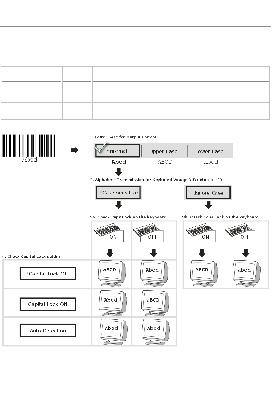
68
1800 Series Handheld RFID Reader Reference Manual
ALPHABETS TRANSMISSION
By default, the alphabets transmission is case-sensitive, meaning that the alphabets will be
transmitted according to their original case, the status of Caps Lock on the keyboard, as well as the
Capital Lock setting. Select [Ignore Case] to have alphabets transmitted according to the status of
Caps Lock on the keyboard only.
Options Parameter Description
Case Sensitive
(Default)
‘0’ Alphabets will be transmitted according to the original case.
Ignore Case ‘1’ Alphabets will be transmitted according to the status of Caps
Lock on the keyboard only.
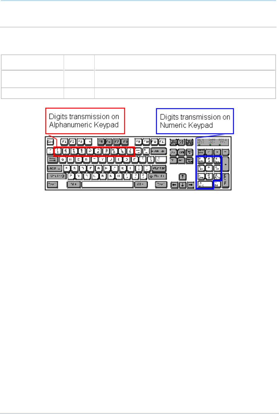
69
Chapter 2
Communication Interface
NUMERIC TRANSMISSION
By default, the alphanumeric keypad is used for transmitting digits. Select “Numeric Keypad” if you
wish to use the keys on the numeric keypad.
Options Parameter Description
Alphanumeric
Keypad (Default)
‘0’ Alphanumeric Keypad will be used for transmitting numeric.
Numeric Keypad ‘1’ Numeric Keypad will be used for transmitting numeric.

70
1800 Series Handheld RFID Reader Reference Manual
2.6.3 INTER-CHARACTER DELAY
By default, the inter-character delay is set to zero. Specify a value, ranging from 0 to 254
in units of millisecond, to match the computer response time of the keyboard interface.
Such delay time is inserted between every character being transmitted. The longer the
delay time is, the slower the transmission speed will be.
Options Parameter Description
‘0’ (Default) ‘0’~‘254’ The range is from 0 to 254 in units of millisecond.
2.6.4 INTER-FUNCTION DELAY
By default, the inter-function delay is set to zero. Specify a value, ranging from 0 to 254
in units of milliseconds, to match the computer response time of the keyboard interface.
Such delay time is inserted between every function code (0x01 ~ 0x1F) being transmitted.
The longer the delay time is, the slower the transmission speed will be.
Options Parameter Description
‘0’ (Default) ‘0’~‘254’ The range is from 0 to 254 in units of millisecond.
2.6.5 HID CHARACTER TRANSMIT MODE
By default, HID interface sends data to the host in batch. You may configure the RFID
Reader to “By Character” to process data one character at a time.
Options Parameter Description
Batch Processing
(Default)
‘0’ Process data by Batch.
By Character ‘1’ Process data by Character
Note: When connecting to an iOS-based device, this parameter must be set to ‘1’.
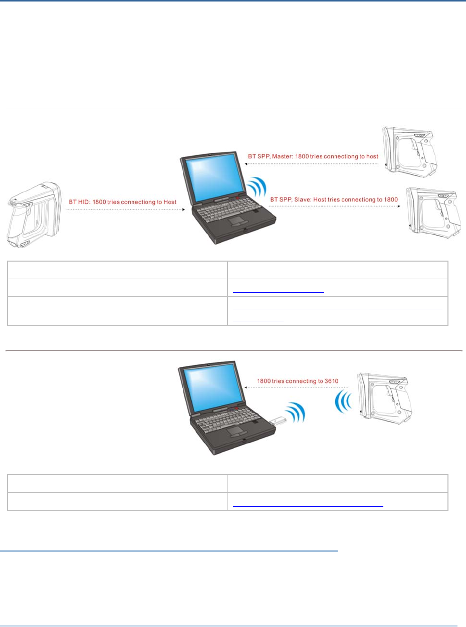
71
RFID Reader can be configured to send data to a host computer wirelessly via the
Bluetooth® and 3610. Upon powering up, RFID Reader will be ready to establish a WPAN
connection.
To establish a connection via Bluetooth® dongle after pairing…
Interface Option Reference
Bluetooth® HID 2.5 Bluetooth® HID
Bluetooth® SPP (Slave/Master) 2.3 Bluetooth® SPP Slave, 2.4 Bluetooth®
SPP Master
To establish a connection via 3610 after finishing relative configurations…
Interface Option Reference
USB VCOM and HID via 3610 2.6 USB VCOM and HID via 3610
IN THIS CHAPTER
3.1 Connecting via Bluetooth® Dongle ................................ 72
3.2 Connecting via 3610 .................................................. 89
3.3 Disconnection............................................................ 92
Chapter 3
SETTING UP A WPAN CONNECTION

72
1800 Series Handheld RFID Reader Reference Manual
3.1 CONNECTING VIA BLUETOOTH® DONGLE
3.1.1 CHANGE INTERFACE
Before establishing a WPAN connection, you can configure the Bluetooth® connection
interface via the USB port.
In the HyperTerminal window, issue “#@bt_type=” command to change the connected
interface and issue “#@bt_type?” command to confirm the used interface at present.
“Activate Bluetooth® HID”, the parameter is ‘5’.
“Activate Bluetooth® SPP Slave Mode”, the parameter is ‘0’.
“Activate Bluetooth® SPP Master Mode”, the parameter is ‘3’.
For example, if you want to use SPP Slave for a connection type, see below:
Command
#@bt_type=0 →set connected interface to ‘0’ for SPP Slave Mode
Response (s)
OK

73
Chapter 3
Settin
g
Up a WPAN Connection
3.1.2 CONFIGURE RELATED SETTINGS
Bluetooth Discoverable
RFID Reader can be configured to hide itself from other devices equipped with Bluetooth® wireless
technology. Simply disable the device name broadcasting setting so that it won’t be discovered by
any other computers.
Command:
#@bt_visible?\r
Purpose Get Bluetooth® Discoverable Status
Response OK,[m]\r (Default m= ‘1’)
[m]: Discoverable
‘0’ – Disable
‘1’ – Enable
ERR,[code]\r
#@bt_visible=[m]\r
Purpose Set Bluetooth® Discoverable Property
Response OK\r
ERR,[code]\r
Note: By default, device name broadcasting is enabled (which is required for initial
connection).
BT POWER SAVING
By default, this feature is enabled, meaning the RFID Reader will listen to the wireless network at a
reduced rate.
Command:
#@bt_ps?\r
Purpose Get Bluetooth® Power Saving
Response OK,[m]\r (Default m= ‘1’)
[m]: Power Saving
‘0’ – Disable
‘1’ – Enable
ERR,[code]\r
#@bt_ps=[m]\r
Purpose Set Bluetooth® Power Saving
Response OK\r

74
1800 Series Handheld RFID Reader Reference Manual
ERR,[code]\r
Note: When connecting more than two devices to a notebook computer with Bluetooth®
wireless technology, we suggest that you disable the Bluetooth® Power Saving
function for a more reliable connection.
AUTHENTICATION
When the authentication and PIN code are changed on the RFID Reader, you have to remove the
RFID Reader from the paired device list (called unpairing) and go through the whole process to
re-establish the connection.
Command:
#@bt_secure?\r
Purpose Get Bluetooth® Authentication
Response OK,[m]\r (Default m= ‘0’)
[m]: Authentication
‘0’ – Disable
‘1’ – Enable
ERR,[code]\r
#@bt_secure=[m]\r
Purpose Set Bluetooth® Authentication
Response OK\r
ERR,[code]\r
With 1800 authentication disabled, the 1800 reader can pair with multiple Bluetooth® devices.
Successful pairing records will be kept for future re-connection without authentication process.
With 1800 authentication enabled, the reader can keep only one pairing record. If the reader pairs
with device A and then pairs with device B, the pairing record of device B will be kept. If device A
wants to connect to the reader, the pairing process must be made again.
If the pairing record on a paired device is cleared, the paired device won’t be able again to pair
with the reader whose authentication is enabled; to solve this problem, users are supposed to
manually clear the pairing record on the reader by issuing “#@BT_RESET” command or using the
function key combination.
PIN CODE
RFID Reader allows up to 16 characters for a PIN code. If the PIN or passkey is incorrect, any
connection requirement will be rejected by RFID Reader. See step 8 in 3.1.3 Bluetooth® HID and
SPP Slave. By default, the PIN code value is “0000”.
Command:
#@bt_pin?\r
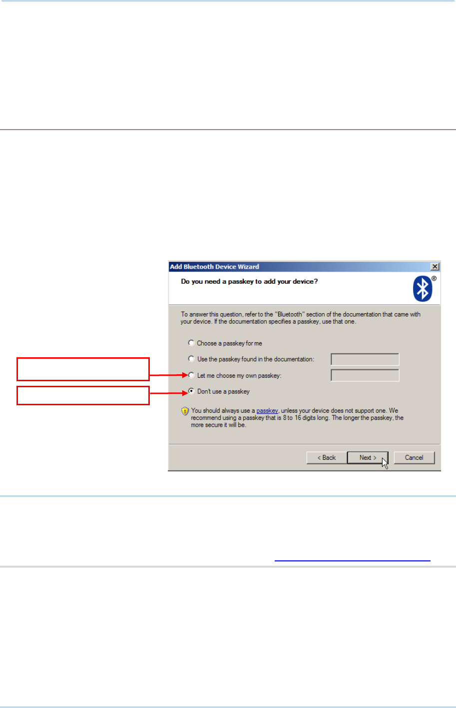
75
Chapter 3
Settin
g
Up a WPAN Connection
Purpose Get Bluetooth® PIN Code
Response OK,[m],[n]\r (Default m= ‘0000’, n= ‘4’)
[m]: length of PIN ‘0’ ~ ‘16’, ‘0’ means no PIN
[n]: PIN, 1~16 characters, only exists when [m]!= ‘0’ (m≠0)
ERR,[code]\r
#@bt_pin=[m],[n]\r
Purpose Set Bluetooth® PIN Code
Response OK\r
ERR,[code]\r
Note: When using Bluetooth® HID, some device driver may not support pre-defined PIN
code for authentication. In this case, make sure you have the RFID Reader set to
“No PIN required” or “User-specified PIN” before pairing. While pairing, the host
PIN code will be displayed on the host computer. Have the RFID Reader to input
the matching PIN code for connection. Refer to 1.3.2 Bluetooth® Pairing Mode.
User-specified PIN
No PIN re
q
uired

76
1800 Series Handheld RFID Reader Reference Manual
SSP (Secure Simple Pairing )
Command:
#@bt_ssp?\r
Purpose Get Bluetooth® SSP Status
Response OK,[m]\r
[m]:SSP Mode
‘0’ – Disable
‘1’ – Enable (Default)
ERR, [code]\r
#@bt_ssp=[m]\r
Purpose Enable/Disable Bluetooth® SSP
Response OK\r
ERR,[code]\r
Note: SSP feature is available only for iOS-based devices currently. We suggest it is
better to enable SSP function when using an iOS-based device.
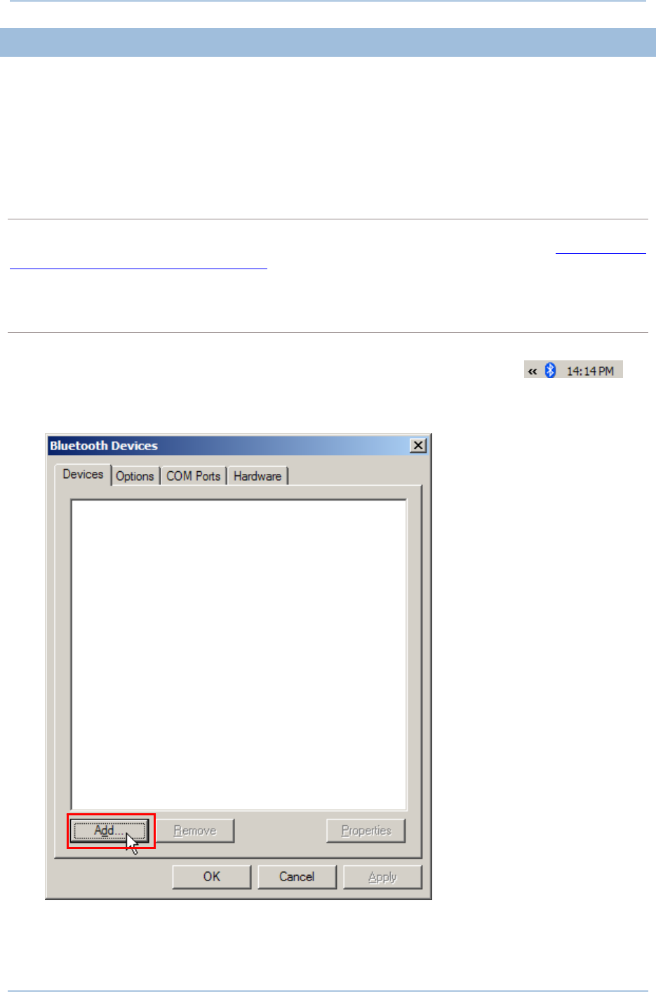
77
Chapter 3
Settin
g
Up a WPAN Connection
3.1.3 BLUETOOTH® HID AND SPP SLAVE
The procedure goes through associating devices for establishing a WPAN connection,
which is pretty much the same except for the software you are using. If your computer is
running Microsoft® Windows® XP (SP1 to SP3), Windows Vista® Service Pack 1 (SP1) and
Windows 7, you can use the software support that Windows® includes, or you can use
the driver that the device manufacturer provides. Now, let’s try using the software
support that Windows® XP Service Pack 2 includes.
BLUETOOTH® HID
By default, the keyboard type of Bluetooth® HID is set to PCAT (US). When Bluetooth® HID is
re-activated, you have to select a keyboard type to complete this setting. Refer to 2.5.1 Activate
Bluetooth® HID & Select Keyboard Type.
Refer to steps 1~11 below for a Bluetooth® connection.
BLUETOOTH® SPP SLAVE
1) Enable the Bluetooth® function on host computer. (Windows® XP only)
2) Double-click the Bluetooth® icon located on the lower right of the taskbar.
Alternatively, you may go to Control Panel > Bluetooth Devices.
3) Click [Add] to search devices nearby.
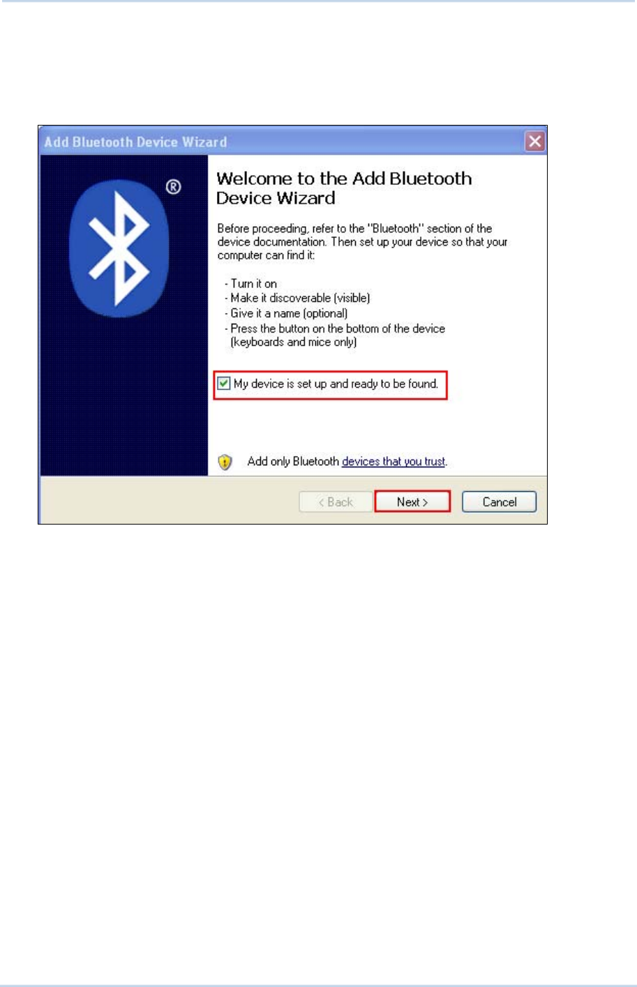
78
1800 Series Handheld RFID Reader Reference Manual
4) Turn on RFID Reader with correct WPAN settings, such as select Bluetooth® SPP Slave or
HID, broadcasting enabled, authentication enabled, and PIN code specified, etc if you want to
use a passkey. Select “My device is set up and ready to be found” check box on the “Add
Bluetooth® Device Wizard” window.
5) Click [Next].
6) Wait for a few seconds for the Wizard to search available devices nearby.
All available devices will appear on the search window. Select the device (e.g. RFID Reader)
that you want to connect.
If the target device does not appear on the list, click [Search Again] to refresh the list. The
RFID Reader might enter power-saving mode during an idling time (=discoverable), and you
can press the <Trigger> to have it active again. It will then stay active for a specified period
of time (2 minutes by default) and wait for the host computer to establish a connection.
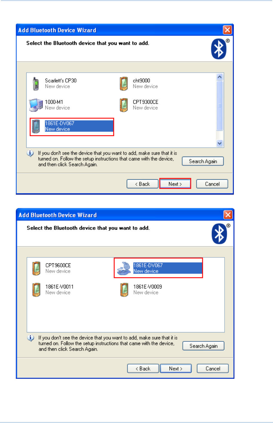
79
Chapter 3
Settin
g
Up a WPAN Connection
7) See SPP Slave connection below, click [Next].
See BT HID connection below, click [Next].
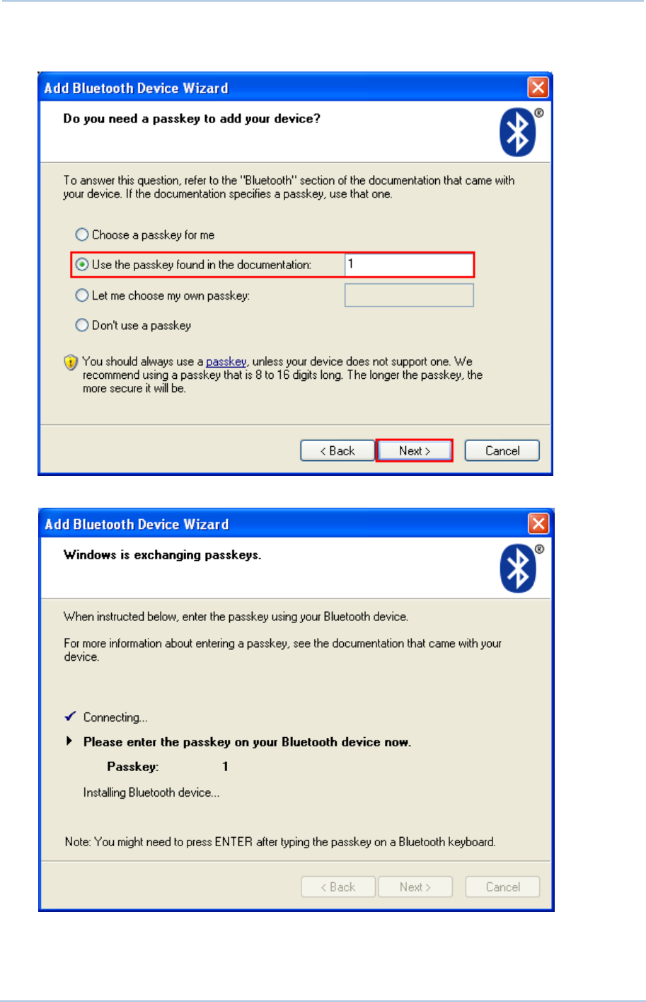
80
1800 Series Handheld RFID Reader Reference Manual
8) Enter the passkey for authentication, which must be exactly the same as configured for
RFID Reader. Click [Next].
9) Wait for a few seconds for Windows to confirm the Passkey.
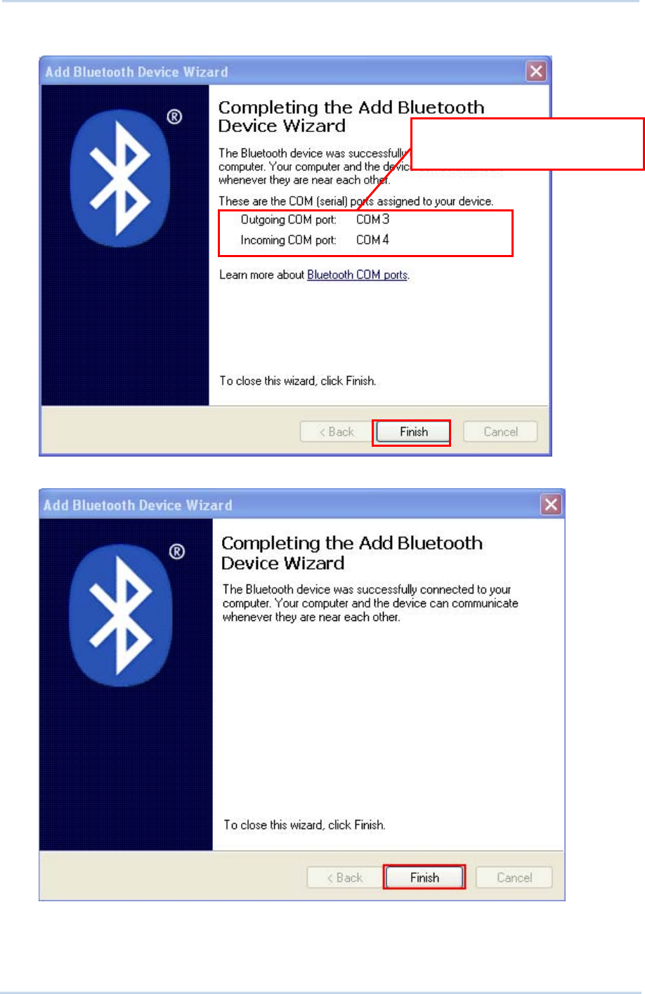
81
Chapter 3
Settin
g
Up a WPAN Connection
10) See SPP Slave connection below, click [Finish].
See BT HID connection below, click [Finish].
RFID Reader as
Bluetooth® SPP Slave
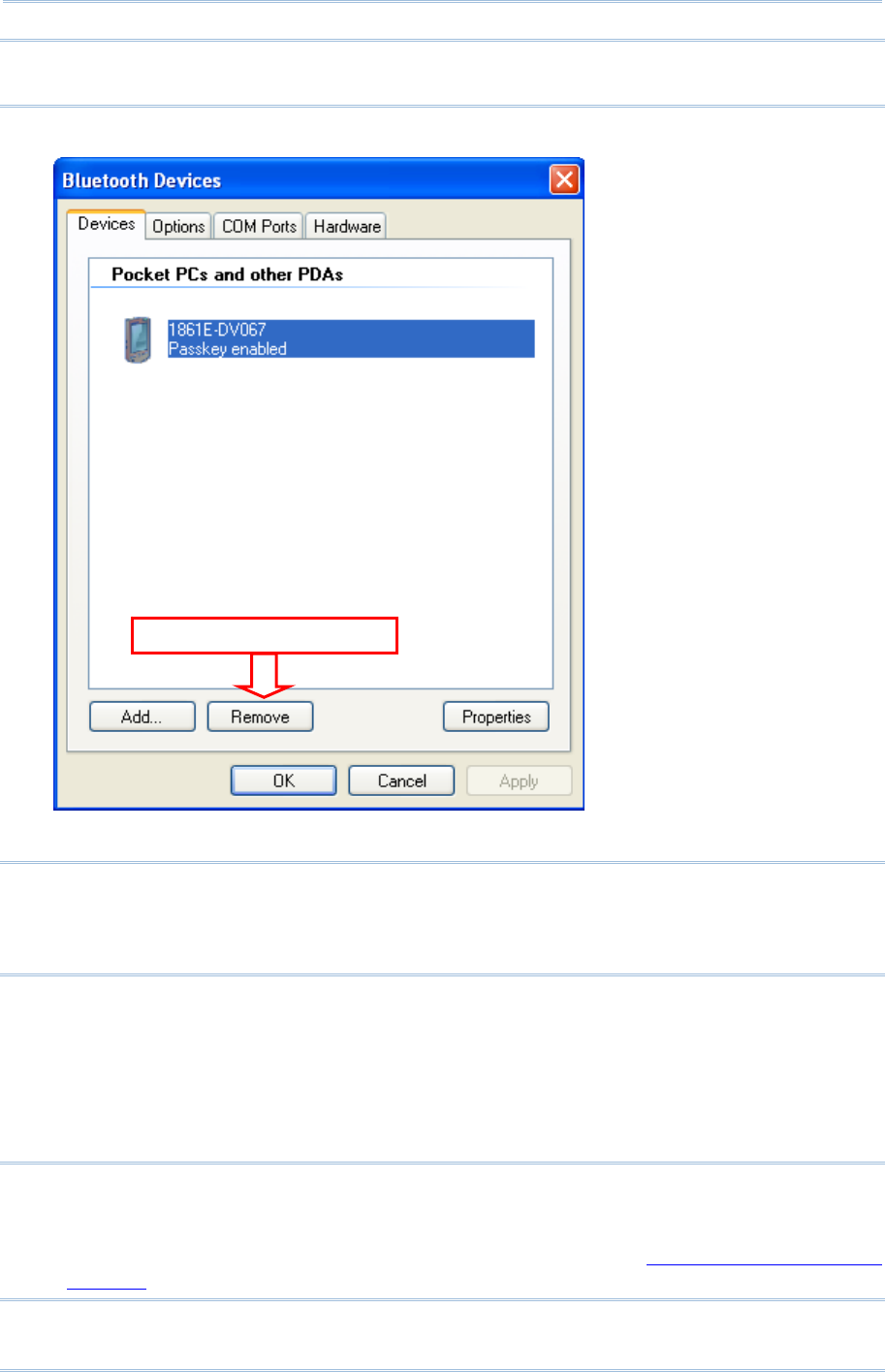
82
1800 Series Handheld RFID Reader Reference Manual
Note: When Bluetooth® security is enabled without providing a pre-set PIN code, the
random PIN code is supported.
11) Now the RFID Reader will be listed as shown below.
Note: When any changes are made to authentication and PIN code on the RFID Reader,
or you want to change RFID Reader to use Bluetooth® HID, it is suggested to
remove the connected RFID Reader from the paired device list (called unpairing)
first and go through the whole process to re-establish the connection.
12) Run the desired application on your computer, such as HyperTerminal.exe if using Bluetooth®
SPP or Notepad.exe if using Bluetooth® HID.
Once the desired application is configured completely, the status of the RFID Reader listed on
the device list will be showed as “Connected”, indicating the WPAN connection is established
successfully via the outgoing COM port if using Bluetooth® SPP Slave.
Note: Even though the RFID Reader is connected to the host with authentication disabled
(= no PIN code required), the host may still request a PIN code while the
application is opening COM port. A random PIN code is supported so that you can
input a matching PIN code on the RFID Reader. Refer to 3.1.2 Configure Related
Settings.
Se
l
ect
a
n
d
R
e
m
o
v
e
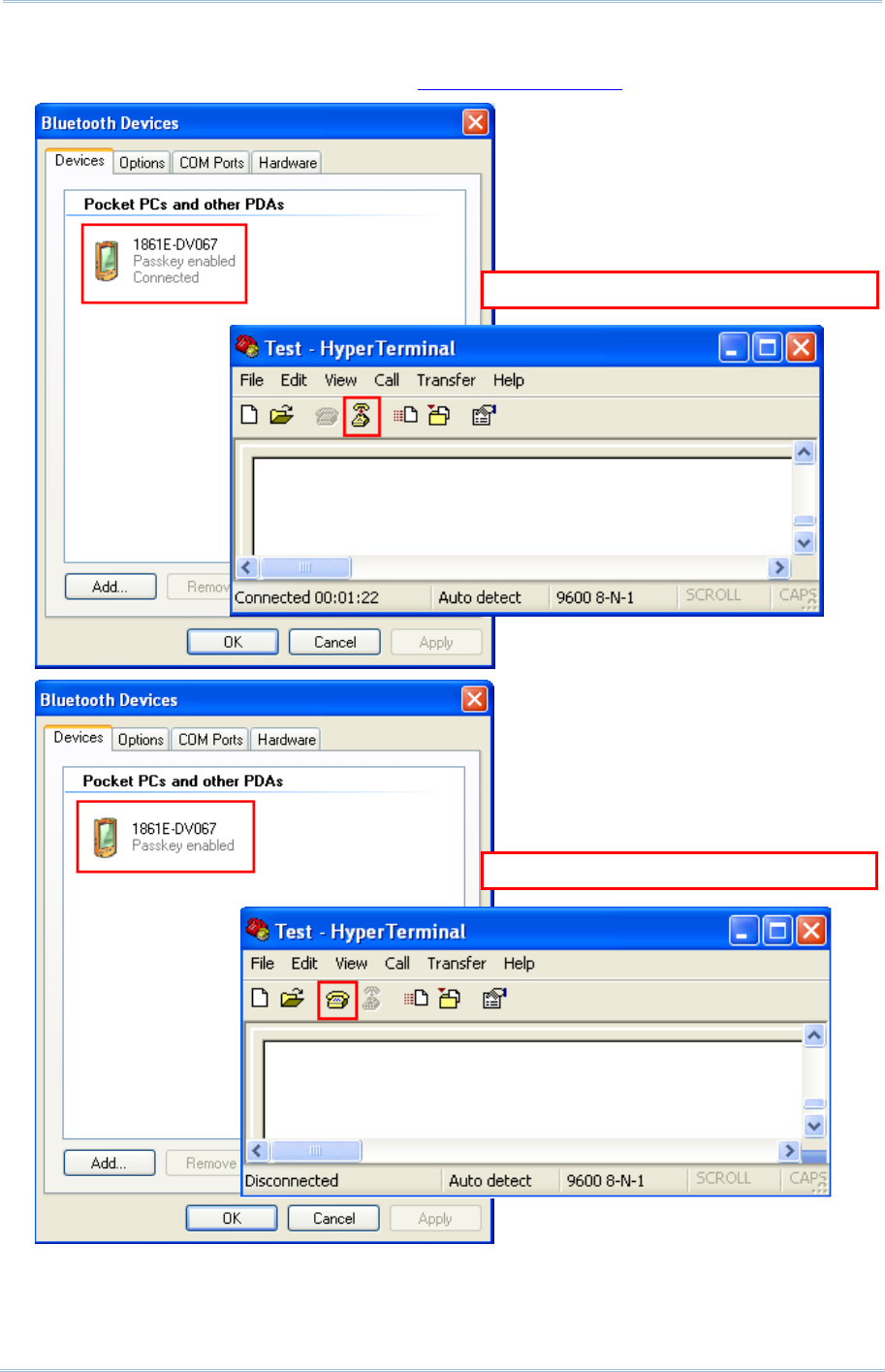
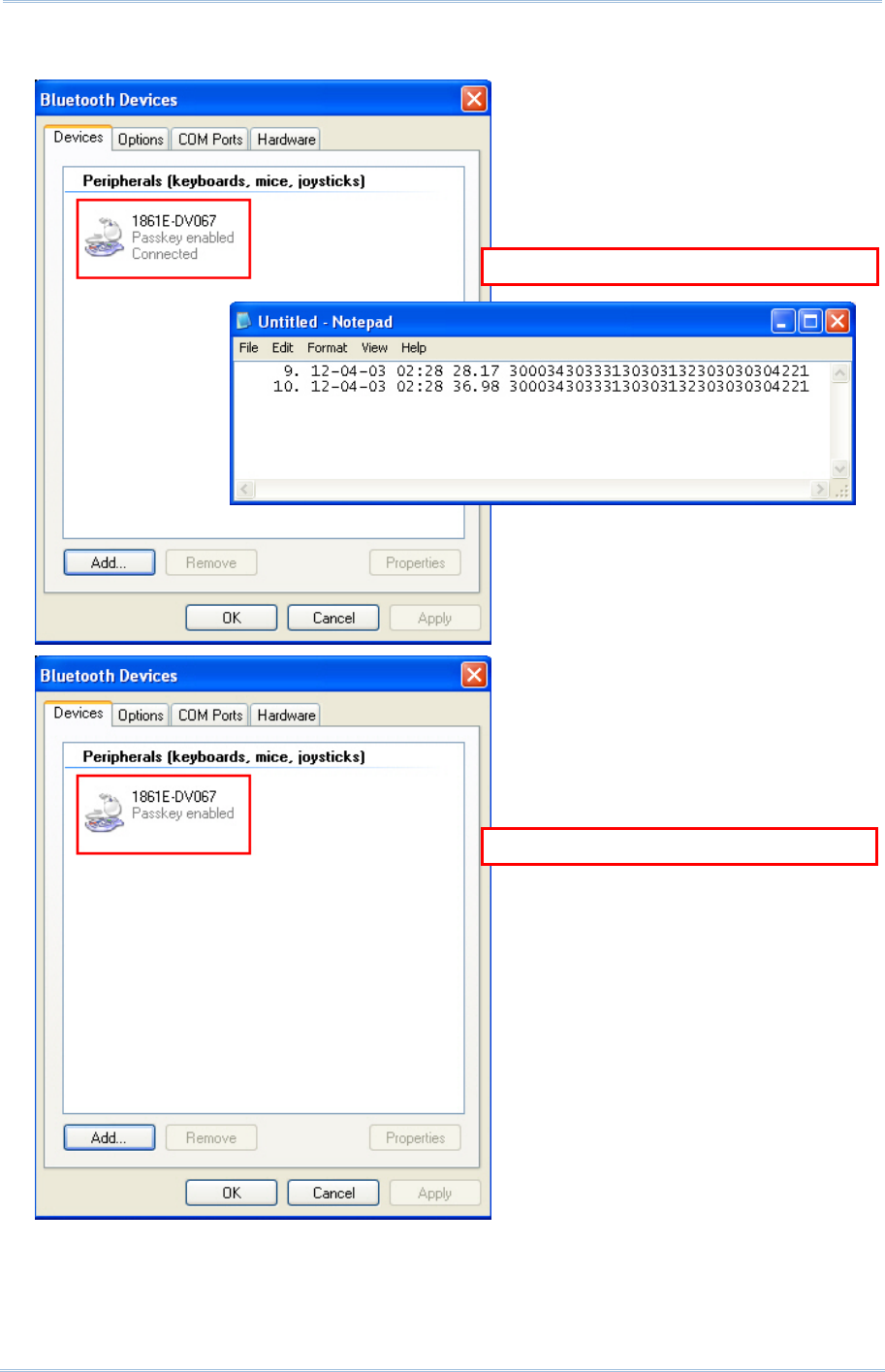
84
1800 Series Handheld RFID Reader Reference Manual
See the comparisons between Bluetooth® HID and Notepad below:
B
luetooth
®
H
ID Connected
B
luetooth
®
HID Disconnected
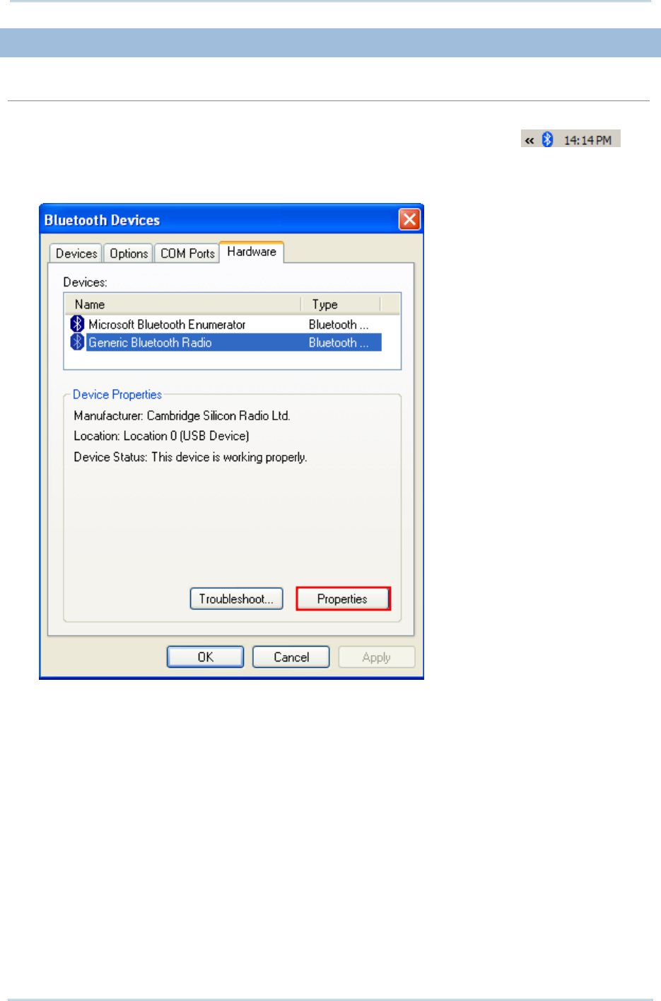
85
Chapter 3
Settin
g
Up a WPAN Connection
3.1.4 BLUETOOTH® SPP MASTER
BLUETOOTH® SPP MASTER
1) Enable the Bluetooth® function on the host computer.
2) Double-click the Bluetooth® icon located on the lower right of the taskbar.
Alternatively, you may go to Control Panel > Bluetooth Devices.
3) Select Hardware tab and click [Properties].
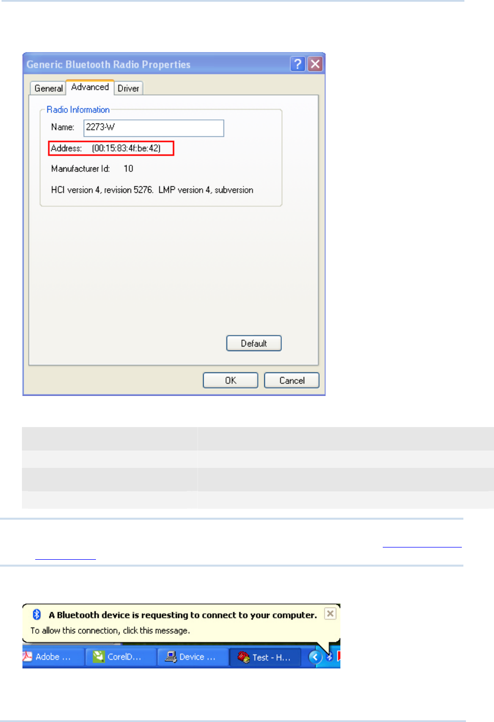
86
1800 Series Handheld RFID Reader Reference Manual
4) In the Generic Bluetooth® Radio Properties window, select Advanced tab to see the Bluetooth®
MACID of host computer.
5) Enable HyperTerminal on the host computer and configure the variables required for
Bluetooth® SPP Master connection.
Command
#@bt_target=0,0015834fbe42 →configure the type and MACID of connected device
Response (s)
OK
Note: When any changes are made to Bluetooth® type, it is suggested to reset the
Bluetooth® connection by “#@bt_reset” command. Refer to 3.3.2 Reset a
Connection.
6) On the host computer, a Bluetooth® connection information box will pop-up on the lower right
of the taskbar. Click it.
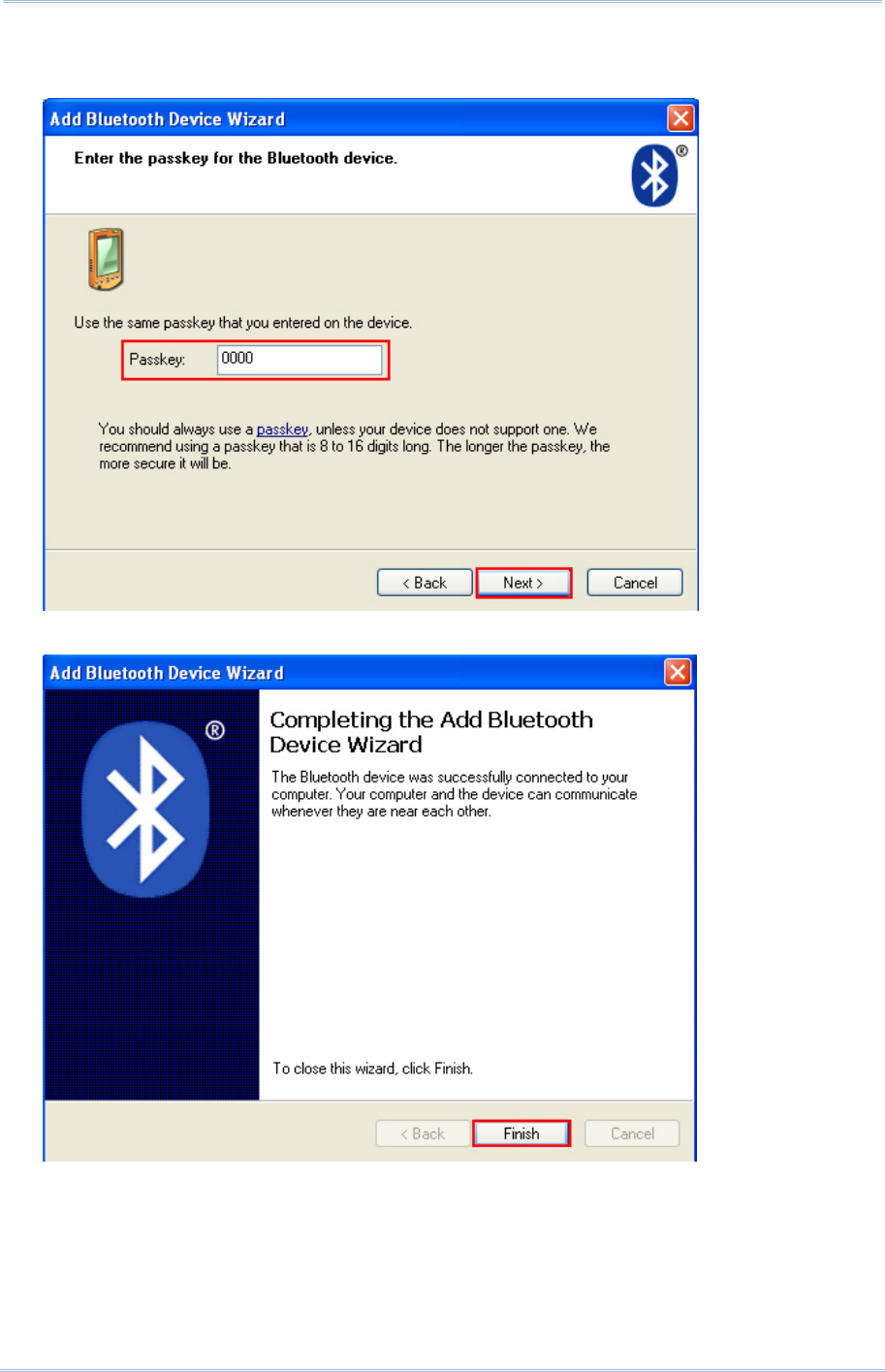
87
Chapter 3
Settin
g
Up a WPAN Connection
7) In the Add Bluetooth® Device Wizard window, key in the passkey that is the same as you
have entered on the RFID Reader. The default value is 0000. Click [Next].
8) Click [Finish].
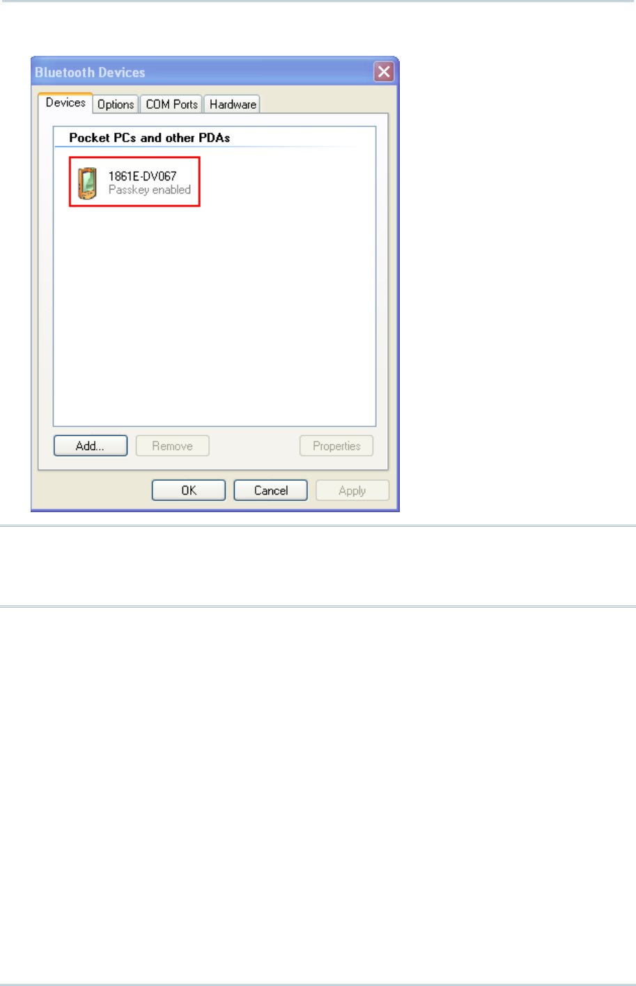
88
1800 Series Handheld RFID Reader Reference Manual
9) In the Bluetooth® Devices configured window will show you connected Device.
Note: When any changes are made to authentication and PIN code on the RFID Reader,
or you want to change to use Bluetooth® HID, it is suggested to remove the
connected RFID Reader from the paired device list (called unpairing) first and go
through the whole process to re-establish the connection.
10) Run the desired application on host computer, such as HyperTerminal.exe if using Bluetooth®
SPP or Notepad.exe if using Bluetooth® HID.
Once the desired application is configured completely, the status of the RFID Reader listed on
the device list will be showed as “Connected”, indicating the WPAN connection is established
successfully.

89
Chapter 3
Settin
g
Up a WPAN Connection
3.2 CONNECTING VIA 3610
3.2.1 CONNECT TO 3610
To configure 3610 connection parameters, the RFID reader must have established a
Bluetooth® connection with 3610. Thus please carry out “#@bt_target=1,xxxxxxxxx\r”
command to establish the connection between them. Once connected, the RFID Reader
will respond with three beeps (tone ascending from low to high), and the LED2 flashes
blue (On/Off ratio 0.02 s: 3 s). When out of range, the RFID Reader will respond with
three short beeps (tone descending from high to low).
3.2.2 USB HID VIA 3610 CONNECTION
If you want to change the USB HID via 3610 interface, use one of the connected RFID
Reader to configure the interface-related settings and it will pass the new settings to
3610, which will then initialize and pass the settings to any other connected device.
1) Power on RFID Reader.
2) Connect RFID Reader to host computer with a USB cable.
3) Enable HyperTerminal on the host computer for issuing commands.
4) Follow Using HyperTerminal to make a USB connection between the host computer
and RFID Reader.
5) Follow 2.6 USB VCOM and HID via 3610 to connect 3610 to the USB port of host
computer. And then make a connection between RFID Reader and 3610.
6) After the connection between RFID Reader and 3610 is established, configure related
settings as below.
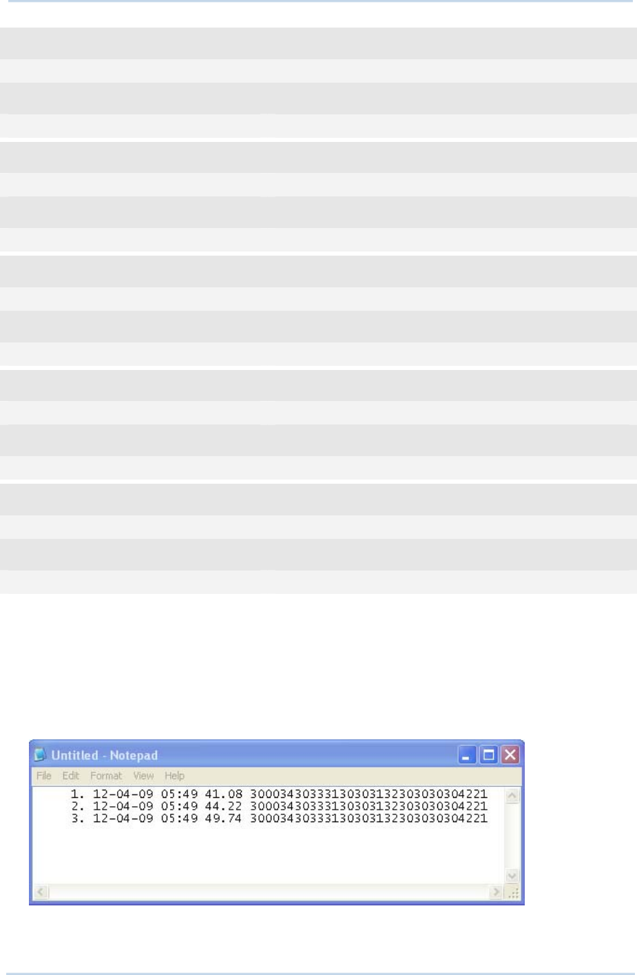
90
1800 Series Handheld RFID Reader Reference Manual
Command
#@bt_aclidx=0 →enter 3610 type configuration
Response (s)
OK
Command
#@bt_aclpr=97 →set to 3610 PCAT US
Response (s)
OK
Command
#@bt_aclidx=4 →enter inter-character delay setting
Response (s)
OK
Command
#@bt_aclpr=10 →set keyboard inter-character delay time to 10ms
Response (s)
OK
Command
#@bt_aclact →activate the settings
Response (s)
OK
7) After the “#@bt_aclact” command is performed, the connection between RFID Reader
and 3610 will disconnect for a while. Once the connection resumes, the interface of
3610 is updated to USB HID.
8) For USB HID via 3610 connection, you can capture the data by running any text
editor, e.g. NotePad on host computer.
9) Once the connection is successful, the scanned data will be transmitted to the
NotePad.

91
Chapter 3
Settin
g
Up a WPAN Connection
3.2.3 USB VCOM VIA 3610 CONNECTION
If you want to change the USB VCOM via 3610 interface, use one of the connected RFID
Reader to configure the interface-related settings and it will pass the new settings to
3610, which will then initialize and pass the settings to any other connected devices.
1) Power on RFID Reader
2) Connect RFID Reader to host computer with a USB cable.
3) Enable HyperTerminal on the host computer for issuing commands.
4) Follow Using HyperTerminal to make a USB connection between the host computer
and RFID Reader.
5) Before using USB VCOM via 3610, you need to install USB VCOM driver. Follow 2.6
USB VCOM and HID via 3610 to connect 3610 to the USB port of host computer. And
then make a connection between RFID Reader and 3610.
6) After the connection between RFID Reader and 3610 is established, configure related
settings as below.
Command
#@bt_aclidx=0 →enter 3610 type configuration
Response (s)
OK
Command
#@bt_aclpr=96 →set to 3610 VCOM
Response (s)
OK
Command
#@bt_aclact →activate the settings
Response (s)
OK
7) After the “#@bt_aclact” command is performed, the connection between RFID Reader
and 3610 will disconnect for a while. Once the connection resumes, the interface of
3610 is updated to Virtual COM.
8) Then 3610 will pass the settings to other connected devices.

92
1800 Series Handheld RFID Reader Reference Manual
3.3 DISCONNECTION
You can follow the methods below to break a connection between RFID Reader and host
computer:
1) Issue #@bt_disc” to disconnect from current connected device.
2) Issue “#@bt_type” to change the connection type. Current connection will be broken.
3) Issue “#@bt_reset” to clear the information of remote device. Current connection will
be broken and connection type will resume to SPP slave.
4) Use Function key to break the connection, refer to 1.4.2 Function Key .
3.3.1 BREAK A CONNECTION
You can force the RFID Reader to break a Bluetooth® connection with host computer by
issuing command.
Command:
#@bt_disc\r
Purpose Break Current Bluetooth® Connection
Response OK\r
ERR,[code]\r
Note: The issues below will also result in
disconnection:
1) Entering power saving mode, refer to 1.1.3 Power Saving Mode.
2) System power off automatically, refer to 1.1.2 Power OFF.
3) Disconnection requirement from the connected device.
3.3.2 RESET A CONNECTION
Perform the “#@bt_reset” command to clear the current pairing record and restore the
connection type to default SPP Slave. Then go through the whole process in Setting Up a
WPAN Connection to establish a new connection.
Command:
#@bt_reset\r
Purpose Reset Bluetooth® Connection
Response OK\r
ERR,[code]\r

93
Equipped with a switch in the handle, the RFID Reader allows you to toggle between
RFID and Alternate modes. Make sure the switch is well-positioned before taking on RFID
scanning tasks. You can also get the status between RFID and Alternate modes by
issuing the “#@rf_switch?” command.
Command:
#@rf_switch?\r
Purpose Get the Status between RFID and Alternate Mode
Response OK,[m]\r (Default m= ‘1’)
[m]: Status of RFID/EXT Switch
‘0’ – EXT Mode (Alternate Mode)
‘1’ – RFID Mode
ERR,[code]\r
IN THIS CHAPTER
4.1 Scan Mode................................................................ 94
4.2 Scan Time ................................................................ 96
4.3 Filter........................................................................ 98
4.4 Multi-Tag.................................................................110
4.5 Access Tag .............................................................114
4.6 Advanced Settings ....................................................121
Chapter 4
SCANNING UHF RFID TAG

94
1800 Series Handheld RFID Reader Reference Manual
4.1 SCAN MODE
RFID Reader scan modes are divided into Single, Multi-Tag and Test Modes. These are
described below.
Scan Mode Description
Single
Mode
Read Tag by pressing <Trigger> key.
1. Condition to start the operation: Press and hold the <Trigger> key.
2. Condition to stop the operation:
(1) A tag is read
(2) <Trigger> key is released.
(3) “Scan Session Timeout” expires while no Tag data is received
(4) New scan mode is set.
3. Release <Trigger> key and press it again to start a new operation cycle.
Scanning Timeout will be refreshed.
Multi-Tag
counter=0
Press and hold the <Trigger> key to read Tag continuously. Repeated
Tags will be accepted.
1. Conditions to start the operation: Press and hold the <Trigger> key.
2. Conditions to stop the operation:
(1) <Trigger> key is released.
(2) New scan mode is set.
3. Scanning speed is controlled by Scanning Delay.
Multi-Tag
Mode
Multi-Tag
counter≠0
Press and hold the <Trigger> key to read Tag continuously. Repeated
Tags will be ignored and new tag’s EPC will be recorded, then counter is
increased.
1. Conditions to start/continue the operation: Press and hold the
<Trigger> key.
2. Conditions to suspend the operation:
(1) Release <Trigger> key.
3. Conditions to stop the operation:
(1) The number of new tags recorded is equal to Multi-Tag counter.
(2) New Multi-Tag Counter is set.
(3) New scan mode is set.
4. The counter of read tag can be reset by command and function key.
5. Scanning speed is controlled by Scanning Delay.
Test Mode Read Tag continuously without pressing the <Trigger>. Capable of decoding the
same tag repeatedly for testing purpose.
1. Conditions to start the operation: Scan mode is set to “Test mode”
2. Conditions to stop the operation: New scan mode is set.

95
Chapter 4
SCANNING UHF RFID
Ta
g
3. Scan Session Timeout, Scanning Delay, Multi-Tag Counter and EPC filter
parameters have no effect in this mode.
4. If RFID Function=Write Tag Memory, the RFID Reader can not be set to Test
Mode.
Command:
#@rf_scan?\r
Purpose Get Scan Mode
Response OK,[m]\r (Default m= ‘6’)
[m]: Scan Mode
‘6’ – Single Mode
‘7’ – Test Mode
‘9’ – Multi – Tag Mode, refer to 4.4 Multi-Tag.
ERR,[code]\r
#@rf_scan=[m]\r
Purpose Set Scan Mode
Response OK\r
ERR,[code]\r

96
1800 Series Handheld RFID Reader Reference Manual
4.2 SCAN TIME
4.2.1 TIMEOUT
You have to specify the scanning timeout interval (0~254 sec.; 0= Disable) when the
scan mode is set to Single Mode.
Operation will stop if the operation time = Scan Session Timeout and No Tag data is
received.
The range of timeout is 0~254 second. By default the value is set to ‘0’ to disable
scanning timeout.
Command:
#@rf_tscan?\r
Purpose Get Scan Session Timeout
Response OK,[m]\r (Default m= ‘0’)
[m]: Timeout, ‘0’ ~ ‘254’
ERR,[code]\r
#@rf_tscan=[m]\r
Purpose Set Scan Section Timeout
Response OK\r
ERR,[code]\r
Note: This command is available for Single Mode. For example, if you set the
“#@rf_tscan” value to 5, the waiting time is set to 5 sec. upon pressing the trigger.
If no tag is scanned within that period, the operation will stop.

97
Chapter 4
SCANNING UHF RFID
Ta
g
4.2.2 DELAY TIME
You can specify the scanning delay time when the scan mode is set to Multi-Tag Mode.
Command:
#@rf_scandly?\r
Purpose Get Scan Delay
Response OK,[m]\r (Default m= ‘0’)
[m]: Scan Delay
‘0’ 100ms
‘1’ 200ms
‘2’ 400ms
‘3’ 800ms
‘4’ 1 sec
‘5’ 2 sec
‘6’ 3 sec
‘7’ 5 sec
ERR,[code]\r
#@rf_scandly=[m]\r
Purpose Set Scan Delay
Response OK\r
ERR,[code]\r
98
1800 Series Handheld RFID Reader Reference Manual
4.3 FILTER
The Flow Chart below is the procedure of scanning tags:
Scan Flow Chart
4.3.1
4.4
4.3.2 4.3.4
4.3.3 4.3.4

99
Chapter 4
SCANNING UHF RFID
Ta
g
4.3.1 EPC ENCODING SCHEME
This function will decide which kind of tags can be read.
Accepted EPC Encoding Scheme – Group 1
Command:
#@rf_epctype1?\r
Purpose Get EPC Scheme – Group1
Response OK,[m]\r (Default = ‘11111111’ )
[m]: EPC Scheme – Group1
8 character series composed of "0" and "1" to enable or disable the listed tag types.
‘0’ – disable the tag type.
‘1’ – enable the tag type.
Character Tag Type
1 (Left) GDTI96
2 GSRN96
3 DoD96S
4 SGTIN96
5 SSCC96
6 GLN96
7 GRAI96
8(Right) GIAI96
e.g. [m]=“10011000” means only to enable GDTI96, SGTIN96,SSCC96
ERR,[code]\r
#@rf_epctype1=[m]\r
Purpose Set EPC Scheme – Group1
Response OK\r
ERR,[code]\r
Accepted EPC Encoding Scheme – Group 2
Command:
#@rf_epctype2?\r
Purpose Get EPC Scheme – Group2
Response OK,[m]\r (Default = ‘11111111’ )
[m]: EPC Scheme – Group2
8 character series composed of "0" and "1" to enable or disable the listed tag types.

100
1800 Series Handheld RFID Reader Reference Manual
0 Æ disable the tag type.
1 Æ enable the tag type.
Character Tag Type
1 (Left) GID96
2 SGTIN198
3 GRAI170
4 GIAI202
5 SGLN195
6 GDTI113
7 ADI
8(Right) Reserved
Always read and write as 1
ERR,[code]\r
#@rf_epctype2=[m]\r
Purpose Set EPC Scheme – Group2
Response OK\r
ERR,[code]\r
Note: If both EPC Scheme Group 1 and 2 are set to “11111111”, it means with accepting
all tags.

101
Chapter 4
SCANNING UHF RFID
Ta
g
4.3.2 AFFECTED TAG OF INCLUDED/EXCLUDED EPC FILTER
Note: The EPC encoding scheme described in Section 4.3.1 allows RFID reader to accept
various types of tag. However, the EPC filter can pick only one type of tag from
those EPC tags; other types will be bypassed.
Command:
#@rf_epcfcode?\r
Purpose Get Tag type that EPC filter works on
Response OK,[m]\r (Default=’30’)
[m]: Acted Scheme for EPC Filter* Tag encoding type
[m] EPC Encoding Scheme
‘2C’ GDTI-96
‘2D’ GSRN-96
‘2F’ USDoD-96
‘30’ SGTIN-96(Default)
‘31’ SSCC-96
‘32’ SGLN-96
‘33’ GRAI-96
‘34’ GIAI-96
‘35’ GID-96
‘36’ SGTIN-198
‘37’ GRAI-170
‘38’ GIAI-202
‘39’ SGLN-195
‘3A’ GDTI-113
‘3B’ ADI
ERR,[code]\r
#@rf_epcfcode=[m]\r
Purpose Set Tag type that EPC filter is applied to
Response OK\r
ERR,[code]\r

102
1800 Series Handheld RFID Reader Reference Manual
4.3.3 INCLUDED EPC
EPC filter is designed to check the contents of the EPC tag with the specified tag type to
determine whether the scanned record is accepted or ignored. Besides configuring the
tag type (refer to Section 4.3.2) to be filtered, users are supposed to specify start bits,
length bits, and EPC pattern when using the EPC filter.
Start Bits
Define the start bit of EPC that you want to filter.
Command:
#@rf_sepcsb?\r
Purpose Get Included EPC Start bit
Response OK,[m]\r (Default m= ‘0’)
[m]: Start bit of EPC. Max. 255 and sum of start bit and pattern length bit cannot be
more than 256.
ERR,[code]\r
#@rf_sepcsb=[m]\r
Purpose Set Included EPC Start bit
Response OK\r
ERR,[code]\r
Length Bits
The Max. value is 256. Sum of star bit and pattern length bit can not be more than 256.
A value from 0 to 256 can be specified.
EPC filter is disabled when the length is set to ‘0’.
Command:
#@rf_sepcl?\r
Purpose Get Included EPC Length
Response OK,[m]\r (Default m= ‘0’)
[m]: Pattern length bits. Max 256 and sum of start bit and pattern length bit cannot
be more than 256.
ERR,[code]\r
#@rf_sepcl=[m]\r
Purpose Set Included EPC Length
Response OK\r
ERR,[code]\r

103
Chapter 4
SCANNING UHF RFID
Ta
g
EPC Pattern
Define the hexadecimal pattern that is used to be compared.
Command:
#@rf_sepcpt?\r
Purpose Get Included EPC Pattern
Response OK,[m]\r (Default m= ‘00’)
[m]: EPC pattern in hexadecimal value.
ERR,[code]\r
#@rf_sepcpt=[m]\r
Purpose Set Included EPC Pattern
Response OK\r
ERR,[code]\r
#@rf_sepcpt2?\r
Purpose Get Included EPC2 Pattern
Response OK,[m]\r (Default m= ‘00’)
[m]: EPC pattern in hexadecimal value.
ERR,[code]\r
#@rf_sepcpt2=[m]\r
Purpose Set Included EPC2 Pattern
Response OK\r
ERR,[code]\r
State
Disable or Enable Included EPC Filter function. When the value is set to ‘1’, Tag EPC will be accepted
upon fitting the required pattern. If the value is set to ‘2’, Tag EPC will be accepted between pattern
and pattern2. (Pattern<=Tag EPC<=Pattern2).
Command:
#@rf_sepcen?\r
Purpose Get Included EPC State
Response OK,[m]\r (Default m= ‘0’)
[m]: ‘0’ – disable, ‘1’ – enable, ‘2’ – enable range filter
ERR,[code]\r
104
1800 Series Handheld RFID Reader Reference Manual
#@rf_sepcen=[m]\r
Purpose Set Included EPC State
Response OK\r
ERR,[code]\r
Note: The pattern must be consistent with length so that you can filter the transmitted
data and accept it.

105
Chapter 4
SCANNING UHF RFID
Ta
g
Example:
Command
#@rf_sepcsb=64 →set filter started from bit 64 of the EPC
Response (s)
OK
Command
#@rf_sepcl=8 →set filter length to 8 bits
Response (s)
OK
Command
#@rf_sepcpt=06 →set filter pattern as 0x06
Response (s)
OK
Command
#@rf_epcfcode=31 →filter works on SSCC-96
Response (s)
OK
Command
#@rf_sepcen=1
Response (s)
OK
Tag1 EPC=3110AFEC2B0BEBC205000000 →reject
Tag2 EPC=3110AFEC2B0BEBC206000000 →accept
Tag3 EPC=3110AFEC2B0BEBC207000000 →reject
Tag4 EPC=3030AFEC2B09C44000000005 →accept. It’s not SSCC-96. Bypass!

106
1800 Series Handheld RFID Reader Reference Manual
4.3.4 EXCLUDED EPC
The following commands are used to "exclude" tags matching the criteria set by the
filter.
Start
Define the start bit of EPC that you want to filter.
Command:
#@rf_xepcsb?\r
Purpose Get Excluded EPC Start bit
Response OK,[m]\r (Default m= ‘0’)
[m]: Start bit of EPC. Max 255 and sum of start bit and pattern length bit cannot be
more than 256.
ERR,[code]\r
#@rf_xepcsb=[m]\r
Purpose Set Excluded EPC Start bit
Response OK\r
ERR,[code]\r
Length
The Max. value is 256. Sum of star bit and pattern length bit can not be more than 256.
A value from 0 to 256 can be specified.
EPC filter is useless when the length is set to ‘0’.
Command:
#@rf_xepcl?\r
Purpose Get Excluded EPC Length
Response OK,[m]\r (Default m= ‘0’)
[m]: Pattern length bits. Max 256 and sum of start bit and pattern length bit cannot
be more than 256.
ERR,[code]\r
#@rf_xepcl=[m]\r
Purpose Set Excluded EPC Length
Response OK\r
ERR,[code]\r

107
Chapter 4
SCANNING UHF RFID
Ta
g
EPC Pattern
Define the hexadecimal pattern that is used to be compared.
Command:
#@rf_xepcpt?\r
Purpose Get Excluded EPC Pattern
Response OK,[m]\r (Default m= ‘00’)
[m]: EPC pattern in hexadecimal value
ERR,[code]\r
#@rf_xepcpt=[m]\r
Purpose Set Excluded EPC Pattern
Response OK\r
ERR,[code]\r
#@rf_xepcpt2?\r
Purpose Get Excluded EPC2 Pattern
Response OK,[m]\r (Default m= ‘00’)
[m]: EPC pattern in hexadecimal value.
ERR,[code]\r
#@rf_xepcpt2=[m]\r
Purpose Set Excluded EPC2 Pattern
Response OK\r
ERR,[code]\r
State
Disable or Enable Excluded EPC Filter function. When the value is set to ‘1’, Tag EPC will be
eliminated upon matching the required pattern. If the value is set to ‘2’, Tag EPC will be eliminated
between pattern and pattern2. (Pattern<=Tag EPC<=Pattern2).
Command:
#@rf_xepcen?\r
Purpose Get Excluded EPC State
Response OK,[m]\r (Default m= ‘0’)
[m]: ‘0’ – disable, ‘1’ – enable, ‘2’ – enable range filter
ERR,[code]\r
108
1800 Series Handheld RFID Reader Reference Manual
#@rf_xepcen=[m]\r
Purpose Set Excluded EPC State
Response OK\r
ERR,[code]\r
Note: The pattern must be consistent with length so that you can filter the transmitted
data.

109
Chapter 4
SCANNING UHF RFID
Ta
g
Example:
Command
#@rf_xepcsb=64 →set filter started from bit 64 of the EPC
Response (s)
OK
Command
#@rf_xepc1=8 →set filter length to 8 bits
Response (s)
OK
Command
#@rf_xepcpt=06 →set filter pattern as 0x06
Response (s)
OK
Command
#@rf_epcfcode=31 →filter works on SSCC-96
Response (s)
OK
Command
#@rf_xepcen=1
Response (s)
OK
Tag1 EPC=3110AFEC2B0BEBC205000000 →accept
Tag2 EPC=3110AFEC2B0BEBC206000000 →reject
Tag3 EPC=3110AFEC2B0BEBC207000000 →accept
Tag4 EPC=3030AFEC2B09C44000000005 →accept. It’s not SSCC-96. Bypass!
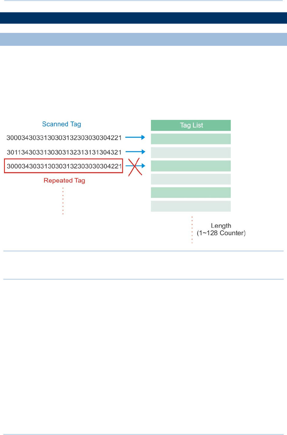
110
1800 Series Handheld RFID Reader Reference Manual
4.4 MULTI-TAG
4.4.1 COUNTER
In order to prevent sending redundant tags to PC or mobile computer, the RFID reader
creates a tag list to compare the scanned tags, discard redundant tags, and output/store
new (unique) tags. The new (unique) tags will be added to the list as the comparing
patterns. To do this we use a counter for that list with the maximum count up to 128
records. When the maximum number of records is reached, the reader will not scan any
tags until the counter is reset.
Note: The Multi-Tag Counter command is used to set the counter value of a tag list. If
the value is set to ‘0’, the list is disabled and all scanned tags are recorded or sent
to PC/mobile computer.

111
Chapter 4
SCANNING UHF RFID
Ta
g
Counter
Command:
#@rf_mtagcnt?\r
Purpose Get Multi-Tag Counter Value
Response OK,[m]\r (Default m= ‘128’)
[m]: Multi-Tag Counter value: ‘0’ (disable the counter), ‘1’ ~‘128’
ERR,[code]\r
#@rf_mtagcnt=[m]\r
Purpose Set Multi-Tag Counter
Request #@rf_mtagcnt=[m]\r
[m]: Multi-Tag Counter
Response OK\r
ERR,[code]\r
Multi-Tag List Type
Command:
#@rf_mtaglist?\r
Purpose Get Multi-Tag List Type
Response OK,[m]\r (Default m= ‘0’)
[m]: Multi-Tag List Type
‘0’ – EPC
‘1’ TID
ERR,[code]\r
#@rf_mtaglist=[m]\r
Purpose Set Multi-Tag List Type
Response OK\r
ERR,[code]\r
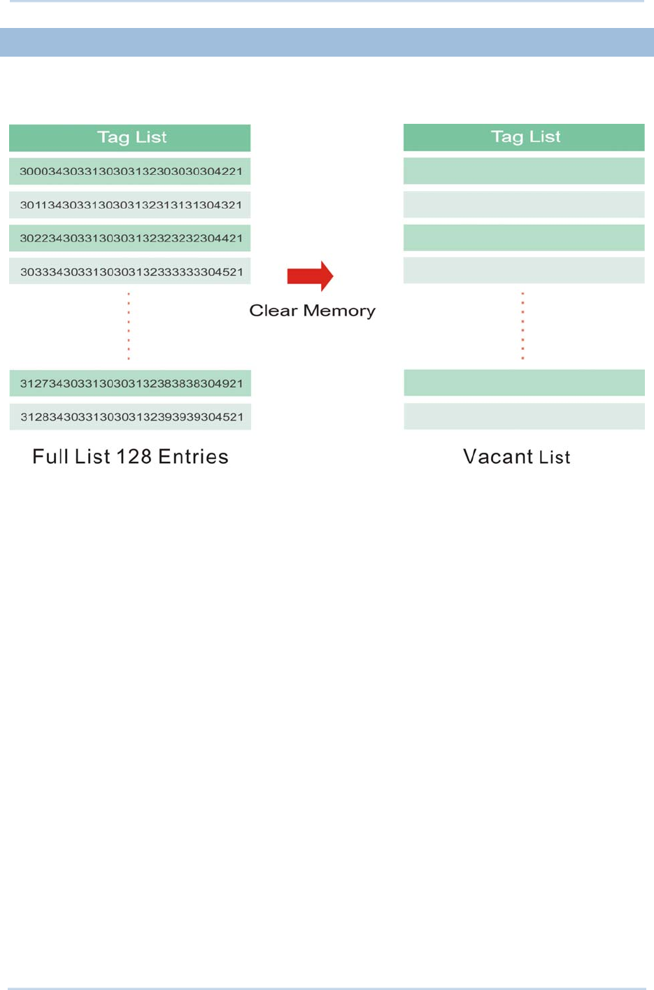
112
1800 Series Handheld RFID Reader Reference Manual
4.4.2 COUNTER RELOAD
When the tag list is full, please issue "#@rf_mtagcnt=[m]\r" command again to reset the
counter. Once reset, the tag list is cleared and scanning tasks can be continued.

113
Chapter 4
SCANNING UHF RFID
Ta
g
4.4.3 MULTI-TAG BEEP
In order to differentiate between tags read, the reader will beep in the following
sequence:
Get a new tag: one short beep with high tone denoting that a tag is scanned
successfully. Please refer to 1.5 Beeper.
Get a repeated tag: one short beep with low tone (disabled by default)
Full Tag List: six short beeps, low-mid-high-low-mid-high (enabled by default)
Beeping Status
Enabling the beeper for multi-tag beeping can be set using the following commands.
Command:
#@rf_mtagbeep?\r
Purpose Get Multi-Tag Beeping
Response OK,[m],[n]\r (Default m= ‘0’, n= ‘1’)
[m]: Repeated Tag Beeping
[n]: Tag List Full Beeping
ERR,[code]\r
#@rf_mtagbeep=[m],[n]\r
Purpose Set Multi-Tag Beeping
Request #@rf_mtagbeep=[m],[n]\r
[m]: Repeated Tag Beeping. ‘0’ – Disable, ‘1’ – Enable
[n]: Tag List Full Beeping. ‘0’ – Disable, ‘1’ – Enable
Response OK\r
ERR,[code]\r
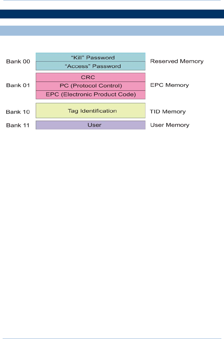
114
1800 Series Handheld RFID Reader Reference Manual
4.5 ACCESS TAG
4.5.1 TAG MEMORY
A tag memory is divided into 4 banks as below:
Reserved Memory:
This area of memory holds the tag’s passwords:
A 32-bit “Kill” password that allows a Tag to be permanently silenced.
- The default Kill password value is zero.
- The Kill command will only execute if the password has been set, i.e. is non-zero.
A 32-bit “Access” password that allows the Tag to transition to the Secured state.
- A Tag in the Secured state can execute all Access commands, including writing to
locked blocks.
Reserved memory can be read-locked.
EPC Memory:
This memory includes three partitions:
A 16-bit CRC
- The actual data is the 1’s complement of the published CRC-16 definition.
A 16-bit Protocol Control (PC)
- 5 bits is for the length of PC + EPC.
- 2 bits is RFU (00
2).
- 9 bits is for a numbering system ID (NSI), which may contain an EPCglobalTM
header or an AFI as defined in ISO 15961.
An EPC (includes Header, General Manager Number, Object Class and Serial Number)
- The electronic product code of the object to which the Tag is attached.

115
Chapter 4
SCANNING UHF RFID
Ta
g
TID Memory:
This memory includes:
An 8-bit ISO 15963 allocation class identifier
- For EPCglobal
TM Tags as 0xE2.
A 12-bit Tag mask-designer ID
A 12-bit Tag model number
Allow to add other information if required e.g. Tag serial number
User Memory:
This optional area of memory contains user-specific data.

116
1800 Series Handheld RFID Reader Reference Manual
4.5.2 READ/WRITE TAG
By default, the RFID Reader access mode is set to Inventory to get EPC of a Tag. If you
want to read all data stored in a Tag, you would issue the “#@rf_func=1” command that
allows you to read Reserved, EPC, TID or User bank.
RFID Function
Command:
#@rf_func?\r
Purpose Get RFID Function
Response OK,[m]\r (Default m= ‘0’)
[m]: RFID Function
‘0’ – Inventory
‘1’ – Read Tag Memory
‘2’ – Write Tag Memory
ERR,[code]\r
#@rf_func=[m]\r
Purpose Set RFID Function
Response OK\r
ERR,[code]\r
Access
Command:
#@rf_rwidx?\r
Purpose Get Index of Access Parameter
Response OK,[m]\r
[m]: Index of Access Parameter
[m] Meaning Value
‘0’ Access Password ‘xxxxxxxx’
Access Password, 4 bytes, shown in Hexadecimal
value.
e.g. String ‘30313233’ indicates 0x30, 0x31, 0x32,
0x33.
Default= ‘00000000’
‘1’ Memory Bank ‘0’ – Reserved Bank

117
Chapter 4
SCANNING UHF RFID
Ta
g
‘1’ – EPC
‘2’ – TID
‘3’ – User Bank
Default= ‘1’
‘2’ Start Byte Only even numbers (‘0’, ‘2’, ‘4’ … ‘32’) are valid for
the start byte.
Default= ‘0’
‘3’ Data Length Byte(s) Only even numbers (‘0’, ‘2’, ‘4’ … ‘32’) are valid for
data length bytes.
Default= ‘0’
ERR,[code]
#@rf_rwidx=[m]\r
Purpose Set Index of Access Parameter
Response OK\r
ERR,[code]\r
#@rf_rwpr?\r
Purpose Get Access Parameter
Response OK,[m]\r
[m]: Access Parameter
ERR,[code]\r
#@rf_rwpr=[m]\r
Purpose Set Access Parameter
Response OK\r
ERR,[code]\r
Write
In addition to specifying parameters mentioned above, you are supposed to store data into RFID
reader’s buffer before writing them into the tag memory.
Command:
#@rf_wbuf?\r
Purpose Get Data in Reader Buffer
Response OK,[m]\r (Default m= ‘0000’)
[m]: Data stored in buffer shown in hexadecimal.
e.g. ‘41’=>0x41= ‘A’ (2 bytes NULL)

118
1800 Series Handheld RFID Reader Reference Manual
ERR,[code]\r
#@rf_wbuf=[m]\r
Purpose Store Data into Reader Buffer
Request #@rf_wbuf=[m]\r
[m]: Data to be stored in buffer
Buffer size = 32 bytes
Input data shown in hexadecimal.
The length of data must be an even number.
To clear the buffer, [m]= ‘0000’
Response OK\r
ERR,[code]\r
Example (Read Tag Memory):
Command
#@rf_rwidx=1
Response (s)
OK
Command
#@rf_rwpr=2 →to read TID Bank
Response (s)
OK
Command
#@rf_rwidx=2
Response (s)
OK
Command
#@rf_rwpr=0 →start from byte 0 of TID Bank
Response (s)
OK
Command
#@rf_rwidx=3
Response (s)
OK

119
Chapter 4
SCANNING UHF RFID
Ta
g
Command
#@rf_rwpr=0 →to read the whole bank
Response (s)
OK
Command
#@rf_func=0 →inventory
Response (s)
OK
1. 12-09-07 10:22 07.91
30003515fd8560082350000000066d36 →after pressing the trigger
Command
#@rf_func=1 →set function to read Tag memory
Response (s)
OK
2. 12-09-07 10:22 46.85
30003515fd8560082350000000066d36e2006001011fcdc5
→after pressing the trigger
(the ‘e2006001011fcdc5’ string is Tag
ID)
Example (Write Tag Memory):
Command
#@rf_rwidx=1
Response (s)
OK
Command
#@rf_rwpr=3 →to write User Bank
Response (s)
OK
Command
#@rf_rwidx=2
Response (s)
OK
Command

120
1800 Series Handheld RFID Reader Reference Manual
#@rf_rwpr=0 →start from byte 0 of User Bank
Response (s)
OK
Command
#@rf_rwidx=3
Response (s)
OK
Command
#@rf_rwpr=8 →to write 8 bytes data
Response (s)
OK
Command
#@rf_wbuf=3132333435363738 →store 8 bytes data into reader buffer before writing
into Tag
Response (s)
OK
Command
#@rf_func=2 →set function to write Tag memory
Response (s)
OK

121
Chapter 4
SCANNING UHF RFID
Ta
g
4.6 ADVANCED SETTINGS
4.6.1 APPLICATIONS IN MULTIPLE TAGS ENVIRONMENT
In an energizing RF field, Tags implement a slot counter into which a random value
involving the Q-parameter is loaded and Readers use the slot counter to regulate the
probability of a Tag responding to commands of the Inventory operation.
In practical applications, the ability of the Reader to read multiple Tags is affected by the
Q value. Greater Q value allows the Reader to identify and collect information from more
Tags; however, the reading distance will thus be decreased, and vice versa. The Q value
should be set to zero in the case of a single Tag field. For the multiple Tags field, Q
should be increased depending on the amount of Tags. A valid Q value can take any
integer between 0 to 15.
Command:
#@rf_q?\r
Purpose Get the Current Q Value
Response OK,[m]\r
[m]: Q value
Valid integer value ranging from 0 to 15 (default=0 for 1861; default=4 for 1862)
ERR,[code]\r
#@rf_q=[m]\r
Purpose Set New Q Value
Request [m]: The number of slots (Q) for the inventory round.
Response OK\r
ERR,[code]\r

122
1800 Series Handheld RFID Reader Reference Manual
4.6.2 ADJUSTMENT FOR OUTPUT POWER LEVEL OF THE READER
Reading distance of the Reader varies according to its output power level. The output
power level is set to the maximum value by default. Users can decrease the power level
for reasons such as:
Within the same frequency band, you may try to prevent RF interference for your own
reason or to comply with the regulations.
For near field applications, you want to write data into the nearest Tag ensuring that
the data won’t be written into neighbouring ones.
Command:
#@rf_plv?\r
Purpose Get the Current Output Power Level of the Reader
Response OK,[m]\r
[m]: Output power level
For 1861, valid power level ranges from 0 to 3. Default value is set to 3.
For 1862, valid power level ranges from 0 to 19. Default value is set to 15.
ERR,[code]\r
#@rf_plv=[m]\r
Purpose Set New Output Power Level of the Reader
Request [m]: Output power level
Response OK\r
ERR,[code]\r

123
You may configure the format of the collected data being output to the host computer.
Data transmission of the tags read can have various formats. The following sections will
describe the available options.
1) Decide the output format.
2) Define the data fields for Time stamp, Data Count and Data sections.
3) Set separators for each section.
4) Define output length of the data.
5) Add Prefix Code and Suffix Code before transmission.
6) Decide the output sequence of Time stamp, Data Count and Data sections.
IN THIS CHAPTER
5.1 Output Format..........................................................124
5.2 Format Editing for Hexadecimal and Raw Data ..............126
5.3 Prefix/Suffix Code .....................................................142
5.4 Output EPC Data via USB Virtual COM..........................145
Chapter 5
DEFINING OUTPUT FORMAT

124
1800 Series Handheld RFID Reader Reference Manual
5.1 OUTPUT FORMAT
Before transmitting data captured by the reader you can edit, add and re-order the
sequence of the final transmitted data. There are standard formats for the specified
interfaces described below.
BT SPP/USB VCOM via 3610
The output formats for Bluetooth® SPP/USB VCOM via 3610 can be one of Packet Data,
Hexadecimal and Raw Data. The default value is Packet Data.
BT HID/USB HID via 3610
The output formats for Bluetooth® HID/USB HID via 3610 can be one of Hexadecimal and
Raw Data. The default value is Hexadecimal.
Note: Bluetooth® HID or USB HID via 3610 interface does not support Packet Data as an
output format.
Command:
#@dat_fmt?\r
Purpose Get Current Output Data Format
Response OK,[m]\r (Default m= ‘0’)
[m]: Output Data Format
[m] BT SPP / USB VCOM via 3610 BT HID / USB HID via 3610
‘0’ Packet Data
‘1’ Hexadecimal
Hexadecimal
‘2’ Raw Data Raw Data
ERR,[code]\r
#@dat_fmt=[m]\r
Purpose Set New Output Data Format
Response OK\r
ERR,[code]\r
Example:
Packet Data:
In order to enhance data reliability during transmission, header and checksum are added
before transmitting. This is normally used for terminal application programming. Please
note that Packet data does not allow any editing features.
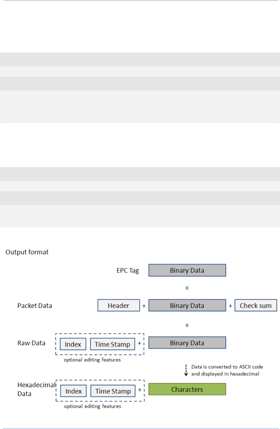
125
Chapter 5
DefinING Output Format
Hexadecimal:
The output data consists of 16 unique symbols, the numbers 0 to 9 and the letters A to F.
Specified for every byte (8 bits) as two consecutive hexadecimal digits. It is easier for
users to read hexadecimal numbers than binary numbers.
Command
#@dat_fmt=1 →set output data format to Hexadecimal Data
Response (s)
OK
1. 12-04-11 23:56 44.46 30003430333130303132303030304221
→ Hexadecimal Data
Raw Data:
As the name implies, raw data output will be recorded and displayed faithfully according
to the original data type. In this case, the output data type will be in Hexadecimal, but
adopting the sequence and options selected by the user.
Command
#@dat_fmt=2 →set output data format to Raw Data
Response (s)
OK
2. 12-04-12 00:03 10.49 040310012000030B! →Raw Data
Please see the picture illustrated below for quick reference.
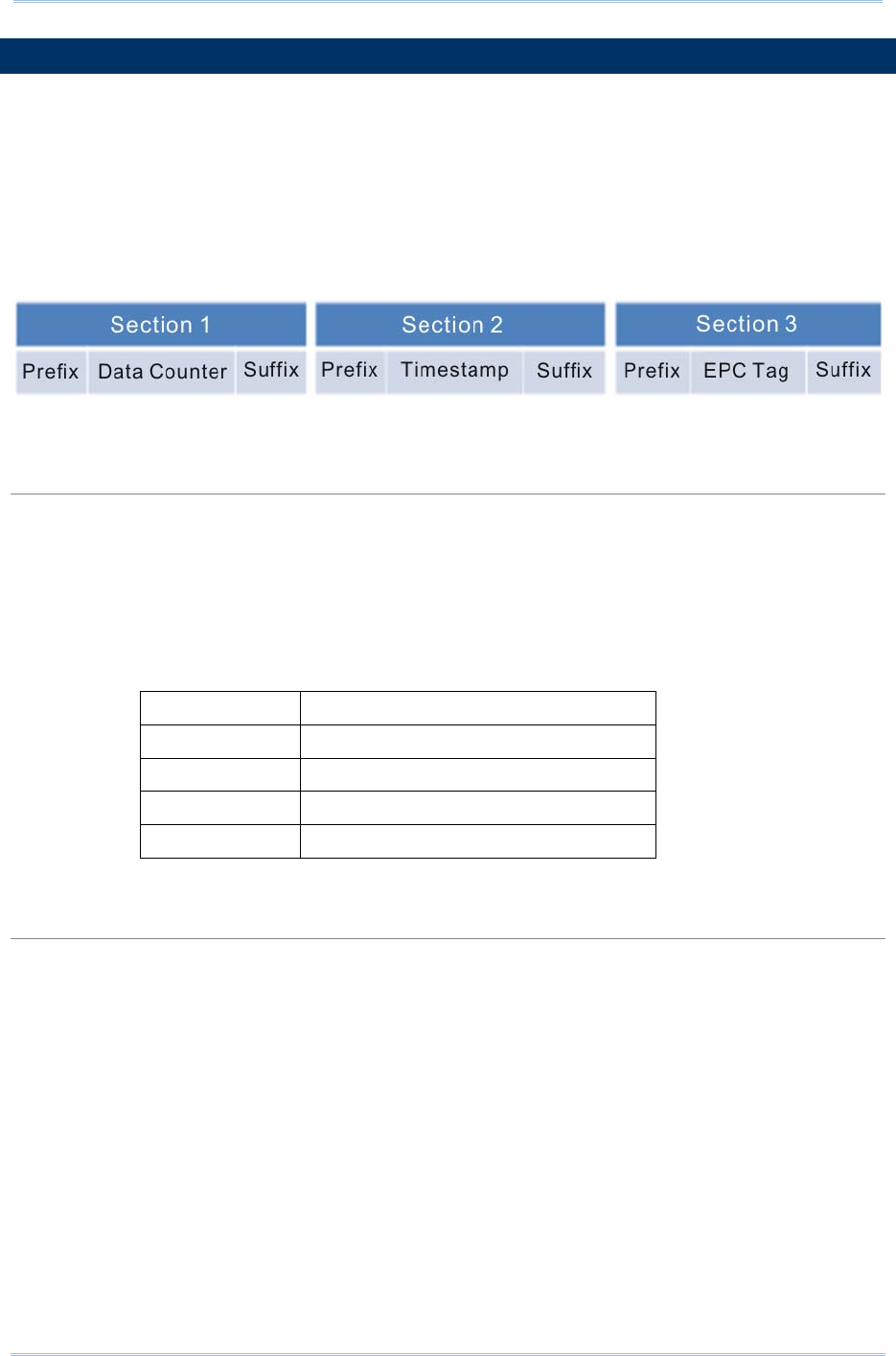
126
1800 Series Handheld RFID Reader Reference Manual
5.2 FORMAT EDITING FOR HEXADECIMAL AND RAW DATA
When the data format is specified for Hexadecimal or Raw Data, you can configure the
data sections described as below:
Each section can be enabled or disabled.
Each section has individual prefix and suffix.
The sequence of sections can be adjusted.
Default Format:
Command:
#@dat_seq?\r
Purpose Get the Setting of Output Data Sequence
Response OK,[m],[n],[o]\r (Default m= ‘1’, n= ‘2’, o= ‘3’)
[m]: Section in sequence 1
[n]: Section in sequence 2
[o]: Section in sequence 3
Data section will be one of the following:
[m]/[n]/[o] Section
‘0’ Disable this section
‘1’ Count section
‘2’ Time Stamp section
‘3’ UHF Data section
ERR,[code]\r
#@dat_seq=[m],[n],[o]\r
Purpose Set Output Data Sequence
Response OK\r
ERR,[code]\r

127
Chapter 5
DefinING Output Format
Example 1:
Sequence 1 : Counter Section
Sequence 2 : Timestamp Section
Sequence 3 : UHF Data Section
Command
#@dat_seq? →get output data sequence
default sequence: Counter, Timestamp, UHF data
Response (s)
OK,1,2,3
Example 2:
Sequence 1 : EPC tag Section
Sequence 2 : Disabled
Sequence 3 : Disabled
Command
#@dat_seq=3,0,0 →set to show EPC tag section only
Response (s)
OK
30003430333130303132303030304221
Example 3:
Sequence 1 : Timestamp Section
Sequence 2 : EPC tag Section
Sequence 3 : Disabled
Command
#@dat_seq=2,3,0 →set to show 1. Timestamp and 2. EPC tag
Response (s)
OK
2012-04-16 Mon 00:08 37.08 30003430333130303132303030304221
sequence 1 sequence 2
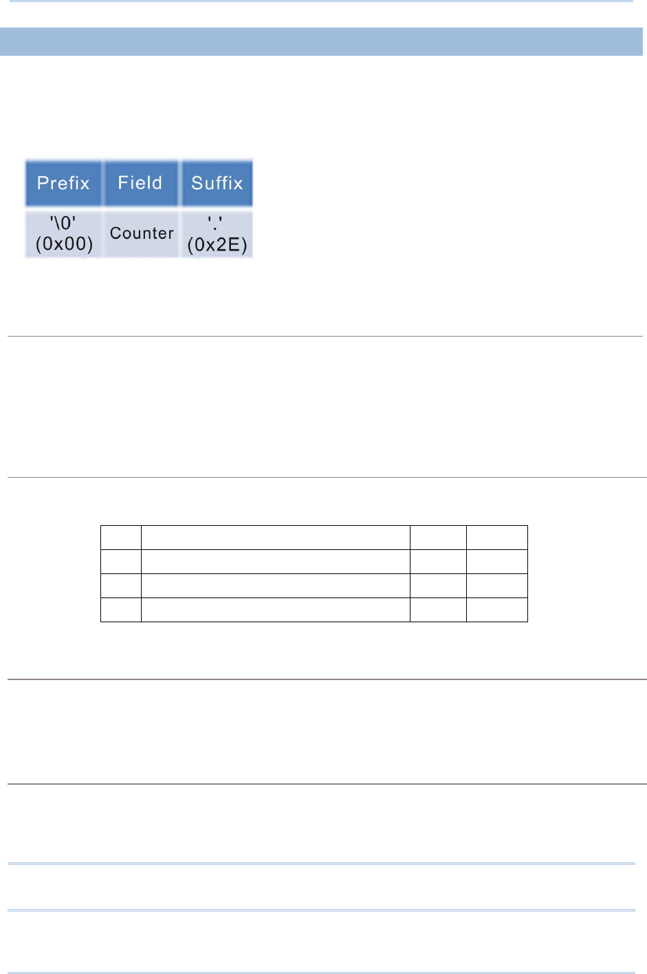
128
1800 Series Handheld RFID Reader Reference Manual
5.2.1 DATA COUNTER SECTION
Define a serial number to output data. The serial number would be specified in 6 digits
beginning from 000001. When the counter is up to 999999, it will be reset to 000001.
Default Format:
Reset Counter Event
There are three events supported to reset the counter. With the parameter set to ‘1’, the
counter will be reset when the event occurs.
Command:
#@dat_rstcnt?\r
Purpose Get the Setting of Reset Counter Event
Response OK,[m],[n],[o]\r (Default m= ‘1’, n= ‘0’, o= ‘1’)
Reset Event Enable
Disable
[m] Reset Counter command accepted ‘1’ ‘0’
[n] UHF Power On ‘1’ ‘0’
[o] new Bluetooth® connection established ‘1’ ‘0’
ERR,[code]\r
#@dat_rstcnt=[m],[n.],[o]\r
Purpose Enable/Disable Counter Reset Event
Response OK\r
ERR,[code]\r
#@dat_rstcnt\r
Purpose Reset Data Counter
Response OK\r
ERR,[code]\r
Note: Besides the configurable events above, Data Counter will also be reset when
system powers up.

129
Chapter 5
DefinING Output Format
Example:
Command
#@dat_rstcnt? →get the values of reset counter events
Response (s)
OK,1,1,1
26. 04-13-2012 30003430333130303132303030304221
Command
#@dat_rstcnt →run the reset counter command
Response (s)
OK
1. 04-13-2012 30003430333130303132303030304221 →re-count
2. 04-13-2012 30003430333130303132303030304221
3. 04-13-2012 30003430333130303132303030304221

130
1800 Series Handheld RFID Reader Reference Manual
Counter Padding
For data display alignment purposes, you can define padding characters to show the
counter value with fixed 6-digit. Characters to be padded or retrieved are shown in
Hexadecimal. Please refer to ASCII Table. The default value is 0x20 (space) for ‘20’
displayed.
Command:
#@dat_cntpad?\r
Purpose Get the Setting of Pad Counter Character
Response OK,[m]\r (Default m= ‘20’ - 0x20 space)
[m]: Character to be padded before data counter, shown in Hexadecimal value.
ERR,[code]\r
#@dat_cntpad=[m]\r
Purpose Set the Character to be Padded before Counter
Response OK\r
ERR,[code]\r
Example:
Command
#@dat_cntpad? →get counter padding
Response (s)
OK,20 →20 is for ‘space’ referred to ASCII table ‘0x20’
10. 04-13-2012 30003430333130303132303030304221
Command
#@dat_cntpad=2a →set counter padding to 2a as ‘*’ referred to ASCII table ‘0x2a’
Response (s)
OK
**** 11. 04-13-2012 30003430333130303132303030304221

131
Chapter 5
DefinING Output Format
5.2.2 TIME STAMP SECTION
Time Stamp section is divided into 7 fields as year, month, day, weekday, hour, minute
and second. Separators can be defined among fields to make more clear presentation. Up
to 6 separators can be specified to Time Stamp section.
Default Format:
Time Stamp Sequence
Issue “#@dat_tseq=” command to configure the fields of Time Stamp section. You can set
the parameter to ‘0’ to disable the field.
Command:
#@dat_tseq?\r
Purpose Get the Sequence Settings of Time Stamp Section
Response OK,[m],[n],[o],[p],[q],[r],[s]\r (Default m= ‘1’, n= ‘2’’, o= ‘3’, p= ‘0’, q= ‘5’, r= ‘6’,
s= ‘7’)
[m]: Time Data Type in Field 1
[n]: Time Data Type in Field 2
[o]: Time Data Type in Field 3
[p]: Time Data Type in Field 4
[q]: Time Data Type in Field 5
[r]: Time Data Type in Field 6
[s]: Time Data Type in Field 7
[m]~[s] Field
‘0’ Disable this Field
‘1’ Year
‘2’ month
‘3’ day
‘4’ weekday
‘5’ Hour
‘6’ Minute
‘7’ second
ERR,[code]\r
#@dat_tseq=[m],[n],[o],[p],[q],[r],[s]\r

132
1800 Series Handheld RFID Reader Reference Manual
Purpose Set the Sequences of Field in Time Stamp Section
Response OK\r
[m]: Time Data Type in Field 1. Default = ‘1’
[n]: Time Data Type in Field 2. Default = ‘2’
[o]: Time Data Type in Field 3. Default = ‘3’
[p]: Time Data Type in Field 4. Default = ‘0’
[q]: Time Data Type in Field 5. Default = ‘5’
[r]: Time Data Type in Field 6. Default = ‘6’
[s]: Time Data Type in Field 7. Default = ‘7’
ERR,[code]\r
Example:
Command
#@dat_tseq=1,2,3,0,0,0,0 →set to show year, month and day only
Response (s)
OK
24. 2012-04-12 30003430333130303132303030304221
Command
#@dat_tseq=2,3,1,0,0,0,0 →change the sequences of year, month and day
Response (s)
OK
25. 04-13-2012 30003430333130303132303030304221
Note: If the field is disabled, its following separator will also be ignored.

133
Chapter 5
DefinING Output Format
Time Stamp Separators
You can configure the separator between fields. The separator to be configured or
retrieved can present in ASCII characters or hexadecimal numbers. Refer to ASCII Table
Command:
#@dat_tsprh?\r, #@dat_tspr?\r
Purpose Get the Separators of Field in Time Stamp Section
Request #@dat_tsprh?\r //Response data will be shown in Hexadecimal value.
#@dat_tspr?\r //Response data will be shown in character.
Response OK,[m],[n],[o],[p],[q],[r]\r
[m]: separator follows field1. Default= ‘2D’ (‘-’)
[n]: separator follows field2. Default= ‘2D’ (‘-’)
[o]: separator follows field3. Default= ‘20’ (‘ ’)
[p]: separator follows field4. Default= ‘20’ (‘ ’)
[q]: separator follows field5. Default= ‘3A’ (‘:’)
[r]: separator follows field6. Default= ‘20’ (‘ ’)
ERR,[code]\r
#@dat_tspr=[m],[n],[o],[p],[q],[r],[s]\r
Purpose Set the Separators of Field in Time Stamp Section
Request #@dat_tspr=[m],[n],[o],[p],[q],[r],[s]\r
[m]: input data format, ‘0’- in Hexadecimal, ‘1’- in character
[n]: separator follows field1
[o]: separator follows field2
[p]: separator follows field3
[q]: separator follows field4
[r]: separator follows field5
[s]: separator follows field6
Response OK\r
ERR,[code]\r
Note: Input ‘00’ (hexadecimal) to clear the inputted data.

134
1800 Series Handheld RFID Reader Reference Manual
Example:
Command
#@dat_tseq=1,2,3,4,5,6,7 →enable all fields
Response (s)
OK
19. 2012-04-12 Thu 23:04 08.34 30003430333130303132303030304221
Command
#@dat_tsprh? →get the separators with hexadecimal format
Response (s)
OK,2d,2d,20,20,3a,20
Command
#@dat_tspr? →get the separators with character format
Response (s)
OK,-,-, , ,:,
Command
#@dat_tspr=0,3a,3a,00,00,00,00 →reset the separators with hexadecimal format
Response (s)
OK
20. 2012:04:12Thu230557.61 30003430333130303132303030304221
Command
#@dat_tspr=1,/,/, ,/,/,/ →reset the separators with character format
Response (s)
OK
20. 2012/04/12 Thu/23/06/34.61 30003430333130303132303030304221

135
Chapter 5
DefinING Output Format
Year
For year output field, you can define it as 2 digits or 4 digits.
Command:
#@dat_tyear?\r
Purpose Get the Setting of Year Field
Response OK,[m]\r (Default m= ‘0’.)
[m]: Year format. 0 – 2 digits, 1 – 4 digits (shown as ‘20xx’).
ERR,[code]\r
#@dat_tyear=[m]\r
Purpose Set the Year Field
Response OK\r
[m]: Year format. m= ‘0’ is for 2 digits, m= ‘1’ is for 4 digits (shown as ‘20xx’).
ERR,[code]\r
Example:
Command
#@dat_tyear? →default format for year is 2 digits
Response (s)
OK,0
3. 12-04-12 05:44 59.47 30003430333130303132303030304221
Command
#@dat_tyear=1 →set year format to 4 digits
Response (s)
OK
4. 2012-04-12 05:44 59.47 30003430333130303132303030304221

136
1800 Series Handheld RFID Reader Reference Manual
Time
You can enable this function to display time in seconds with the scale of two digits to the
right of the decimal point if second field is enabled.
Command:
#@dat_tms?\r
Purpose Get Time Format
Response OK,[m]\r (Default m= ‘1’)
[m]: Display time in seconds with two digits after the decimal point.
0 – Disable, 1 – Enable
ERR,[code]\r
#@dat_tms=[m]\r
Purpose Set to Display Time
Request #@dat_tms=[m]\r
[m]: Display time in seconds with two digits after the decimal point.
0 – Disable, 1 – Enable
Response OK\r
ERR,[code]\r
Example:
Command
#@dat_tms? →get the displaying format of seconds
Response (s)
OK,1
5. 2012-04-12 05:44 59.47 30003430333130303132303030304221
display↑ time in seconds with two digits after the decimal point
Command
#@dat_tms=0 →set to display time in seconds without decimals
Response (s)
OK
6. 2012-04-12 05:44 59 30003430333130303132303030304221
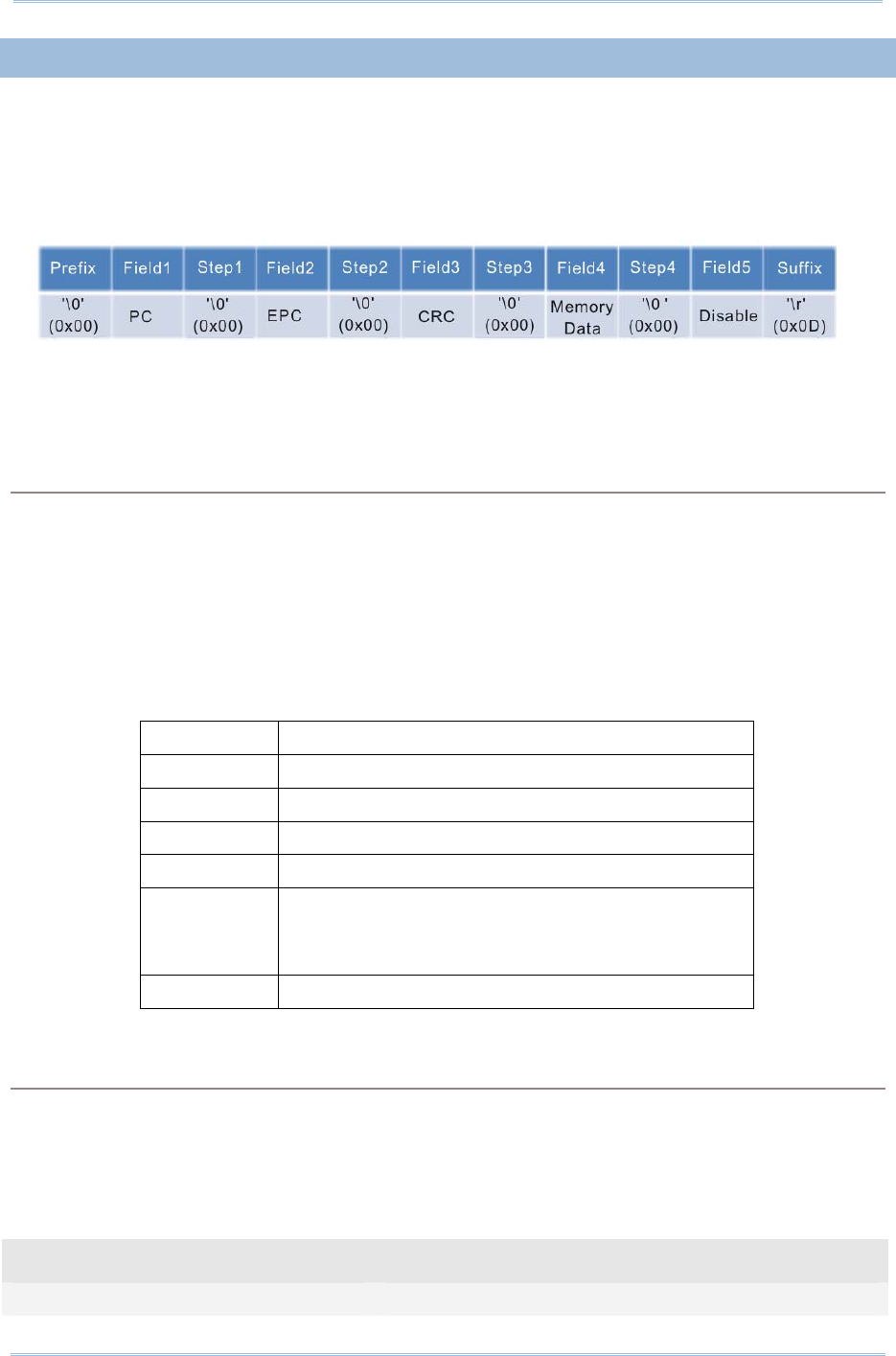
137
Chapter 5
DefinING Output Format
5.2.3 EPC TAG SECTION
The EPC tag section is divided into 5 fields as PC, EPC, CRC, Memory Data and Data
Length. Separators can be defined among fields for clarity. Up to 4 separators can be
specified for this section.
Default Format:
Command:
#@dat_rfseq?\r
Purpose Get the Sequence Setting of EPC Tag Data Section
Response OK,[m],[n],[o],[p],[q]\r
[m]: EPC Tag Data in Field 1 (default: ‘2’ – PC)
[n]: EPC Tag Data in Field 2 (default: ‘3’ – EPC)
[o]: EPC Tag Data in Field 3 (default: ‘1’ – CRC)
[p]: EPC Tag Data in Field 4 (default: ‘4’ – Memory Data)
[q]: EPC Tag Data in Field 5 (default: ‘0’ – Disable)
[m]~[q] Description
‘0’ Disable this Field
‘1’ CRC
‘2’ PC
‘3’ EPC
‘4’ Memory Data
This field only appears when RFID function is set to
“Read Tag Memory”
‘5’ Data Length
ERR,[code]\r
#@dat_rfseq=[m],[n],[o],[p],[q]\r
Purpose Set the Sequence of Each Field in EPC Tag Data Section
Response OK\r
ERR,[code]\r
Example:
Command
#@rf_func? →get RFID function

138
1800 Series Handheld RFID Reader Reference Manual
Default is inventory
Response (s)
OK,0
18. 2012-04-12 Fri 04:00 55.95 30003430333130303132303030304221
Command
#@dat_rfseq? →get the sequence of RFID Data
Default sequence is PC, EPC and then CRC
Response (s)
OK,2,3,1,4,0
19. 2012-04-12 Fri 04:00 55.95 3000 343033313030313230303030 4221
PC + EPC + CRC
Command
#@dat_rfseq=3,0,0,0,0 → only show EPC
Response (s)
OK
20. 2012-04-12 Fri 04:00 55.95 343033313030313230303030
EPC
UHF Data Separators
The separator to be configured or retrieved can present in ASCII characters or
hexadecimal numbers. Refer to ASCII Table.
Command:
#@dat_rfsprh?\r, #@dat_rfspr?\r
Purpose Get the Separators of Each field in EPC Tag Data Section
Request #@dat_rfsprh?\r Response data will be shown in Hexadecimal value
#@dat_rfspr?\r Response data will be shown in character
Response OK,[m],[n],[o],[p]\r
[m]: separator follows field1. Default= ‘00’ (NULL)
[n]: separator follows field2. Default= ‘00’ (NULL)
[o]: separator follows field3 . Default= ‘00’ (NULL)
[p]: separator follows field4 . Default= ‘00’ (NULL)
ERR,[code]\r
#@dat_rfspr=[m],[n],[o],[p],[q]\r

139
Chapter 5
DefinING Output Format
Purpose Set the Separators of Each field in EPC Tag Data Section
Request #@dat_ rfspr=[m],[n],[o],[p],[q]\r
[m]: input data format, ‘0’- in Hexadecimal, ‘1’- in character
[n]: separator between field1 and field2
[o]: separator between field2 and field3
[p]: separator between field3 and field4
[q]: separator between field4 and field5
Response OK\r
ERR,[code]\r
Note: Input ‘00’ (hexadecimal) to clear the inputted data.
Example:
Command
#@dat_rfspr? →get the separators in character format
Response (s)
OK,
Command
#@dat_rfsprh? →get the separators in hexadecimal format
Response (s)
OK,00,00,00,00
21. 2012-04-12 Fri 04:00 55.95 34303331303031323030303030004221
Command
#@dat_rfsprh=0,2d,2d,2d,2d →reset the separators using hexadecimal format
e.g. 2d is specified for ‘-’
Response (s)
OK
22. 2012-04-12 Fri 04:00 55.95 343033313030313230303030-3000-4221-
Command
#@dat_rfsprh=1,/,/,/,/ →reset the separators using character format
Response (s)
OK
23. 2012-04-12 Fri 04:00 55.95 343033313030313230303030/3000/4221/
Note: If a specific field is disabled, its following separator will be ignored.

140
1800 Series Handheld RFID Reader Reference Manual
Data Length
Enable the Data Length function to show the length for UHF Data, EPC and memory data.
Command:
#@dat_rflen?\r
Purpose Get the Setting of UHF Data Length
Response OK,[m]\r (Default m= ‘0’)
[m]: Data Length Type
‘0’- Total UHF Data Length. Separators are not included.
‘1’- EPC Length
‘2’- Memory Data Length
ERR,[code]\r
Note: UHF data length is not related to the appearance of fields. For example, when the
field is set to display EPC data only with data length set to “Total UHF Data Length”, data
length will include PC and CRC data even though the two data fields are not displayed.
#@dat_rflen=[m]\r
Purpose Set the RFID Data Length
Response OK\r
ERR,[code]\r
Example:
Command
#@dat_rfseq? →get the sequence of RFID data
Response (s)
OK,2,3,1,4,0 →default data length is ‘0’ not transmitted
33. 2012-04-12 Fri 04:00 55.95 34303331303031323030303030004221
Command
#@dat_rfseq=2,3,1,4,5 →set to ‘5’ to display data length
Response (s)
OK,2,3,1,4,5
34. 2012-04-12 Fri 04:00 55.95 3430333130303132303030303000422116
→total data length is 16 bytes including PC (2 bytes), EPC (12 bytes), and (CRC 2 bytes)

141
Chapter 5
DefinING Output Format
Command
#@dat_rflen? →get the RFID data length setting
Response (s)
OK,0
35. 2012-04-12 Fri 04:00 55.95 3430333130303132303030303000422116
→display total data length
Command
#@dat_rflen=1 →change the value to 1 displaying the EPC length only
Response (s)
OK,2,3,1,4,5
36. 2012-04-12 Fri 04:00 55.95 3000343033313030313230303030422112
→EPC data length is 12 bytes
Command
#@dat_rflen=2 → change the value to 2 displaying the Memory data
length only
Response (s)
OK
37. 2012-04-12 Fri 04:00 55.95 300034303331303031323030303042210
→ fail to read the Tag Memory data so the data length is 0

142
1800 Series Handheld RFID Reader Reference Manual
5.3 PREFIX/SUFFIX CODE
Prefix/Suffix codes can be utilized for applications like data section prompt string,
separating string, carriage return or other auxiliary data-identification. Each data section
has its own individual prefix/suffix codes up to 8 bytes.
Prefix/Suffix Index
For a prefix or suffix index, you have to specify for which section (e.g. Data Counter, Time
Stamp or EPC Tag Data) you want to apply it to.
Command:
#@dat_pfxidx?\r
Purpose Get Prefix/Suffix Buffer Index
Response OK,[m]\r
[m]: Prefix / Suffix Index
[m] Description
‘1’ Prefix of Data Counter Section
‘2’ Suffix of Data Counter Section
‘3’ Prefix of Time Stamp Section
‘4’ Suffix of time Stamp Section
‘5’ Prefix of EPC Tag Data Section
‘6’ Suffix of EPC Tag Data Section
ERR,[code]\r
#@dat_pfxidx=[m]\r
Purpose Specify Prefix/Suffix Buffer Index
Response OK\r
ERR,[code]\r

143
Chapter 5
DefinING Output Format
Prefix/Suffix
Command:
#@dat_pfxh?\r, #@dat_pfx?\r
Purpose Get Prefix/Suffix
Request #@dat_pfxh?\r Response data will be shown in Hexadecimal value
#@dat_pfx?\r Response data will be shown in character
Response OK,[m]\r
[m]: Prefix/Suffix stored in the index-specified buffer
ERR,[code]\r
#@dat_pfx= [m],[n]\r
Purpose Set Prefix/Suffix
Response OK\r
[m]: input data format, ‘0’- in Hexadecimal, ‘1’- in character
[n]: Prefix/Suffix to be stored in the index-specified buffer
ERR,[code]\r
Default
Prefix of Counter Section ‘00’ (NULL)
Prefix of Time Stamp Section ‘20’ (SPACE)
Prefix of EPC Tag Data Section ‘00’ (NULL)
Suffix of Counter Section ‘2E’ (.)
Suffix of Time Stamp Section ‘20’ (SPACE)
Suffix of EPC Tag Data Section ‘0D’ (CR)

144
1800 Series Handheld RFID Reader Reference Manual
Example1 (Prefix of the Counter Section):
Command
#@dat_pfx=0,23 →set prefix to 0x23 (‘#’)
Response (s)
OK
# 39. 2012-04-12 Fri 04:00 55.95 3000343033313030313230303030422112
Command
#@dat_pfx=0,23436f756e74657223
→set prefix to
0x23、0x43、0x6f、0x75、0x6e、0x74、0x65、0x72、0x23
(respective characters are: #、C、o、u、n、t、e、r、#);
the length exceeds 8 bytes so the last code 0x23 (‘#) will
be truncated.
Response (s)
OK
#Counter 40. 2012-04-12 Fri 04:00 55.95 30003430333130303132303030304221
Command
#@dat_pfx=1,@ →set prefix to ‘@’
Response (s)
OK
@ 41. 2012-04-12 Fri 04:00 55.95 30003430333130303132303030304221
Example2 (Suffix of the EPC Data Section):
Command
#@dat_pfxidx=6 →setting the prefix/suffix buffer index to 6 means to
configure the suffix of the EPC data section
Response (s)
OK
Command
#@dat_pfx=0,454e440d →set the suffix to 0x45、0x4e、0x44、0x0d (respective
characters are: E, N, D, \r)
Response (s)
OK
42. 2012-04-12 Fri 04:00 55.95 30003430333130303132303030304221END

145
Chapter 5
DefinING Output Format
5.4 OUTPUT EPC DATA VIA USB VIRTUAL COM
Users can decide whether to output data via the USB Virtual COM port. Once the ‘m’
parameter of this command is set to ‘1’, the EPC data originally transmitted by
Bluetooth® communications will be output by the USB Virtual COM port. Thus, Bluetooth®
communications stop outputting the EPC data.
Command:
#@dat_2usb?\r
Purpose Get the Setting Value
Response OK,[m]\r
[m]: Output EPC Data via USB Virtual COM
‘0’ Disable (default)
‘1’ Enable outputting EPC Data via USB Virtual COM
ERR,[code]\r
#@dat_2usb=[m]\r
Purpose Specify the Setting
Response OK\r
ERR,[code]\r

146
1800 Series Handheld RFID Reader Reference Manual
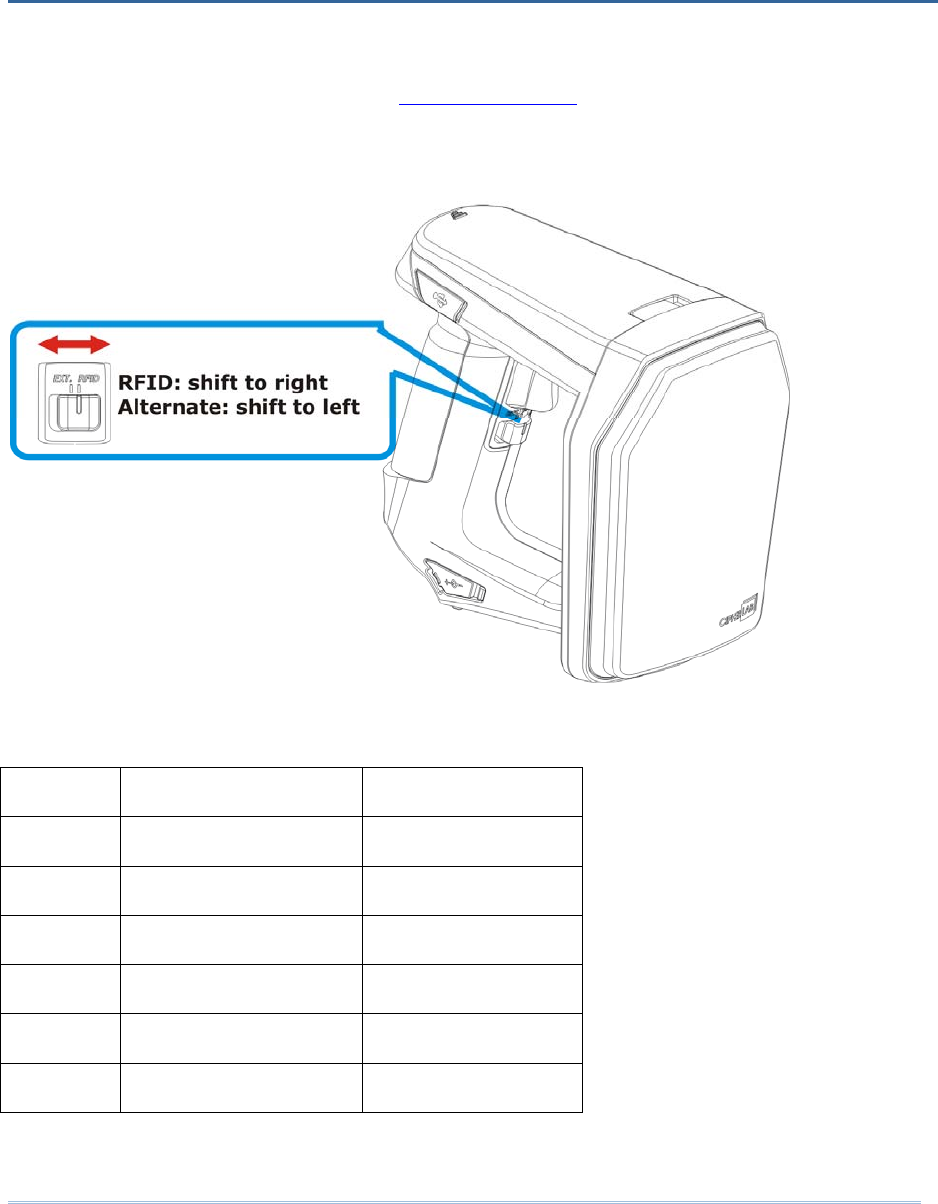
147
Shift the reader switch to the EXT. position to have 1800 RFID reader enter Alternate
mode. In Alternate mode, 1800 RFID reader won’t read tags with the trigger being
pressed. Function keys described in 1.3.1 RFID Mode are also not available. Instead,
defined key events are sent to the mobile computer as strings.
You can transmit the specified key actions to host via Bluetooth® in Alternate mode. The
reader supports up to 6 output strings and 8 key actions for users to select or edit.
Index Key Action String (10byte)
1 1 (Press Trigger) #@TRIG_ON\r
2 2 (Release Trigger) #@TRIG_OFF\r
3 0 (Disable) NULL
4 0 (Disable) NULL
5 0 (Disable) NULL
6 0 (Disable) NULL
Table 6.1: Default output string and key action combination table
Chapter 6
ALTERNATE MODE

148
1800 Series Handheld RFID Reader Reference Manual
Output String
Define the string first before defining the action to be executed.
Command:
#@dat_ostridx?\r
Purpose Get Output String index
Response OK,[m]\r (Default m= ‘1’)
[m]: String Buffer Parameter 1~6
ERR,[code]\r
#@dat_ostridx=[m]\r
Purpose Set Output String index
Response OK\r
ERR,[code]\r
Key Action
Command:
#@dat_ostrkey?\r
Purpose Get Key Action of Output String
Response OK,[m]\r
[m]: Key Action
[m] Action
‘0’ Disable
‘1’ Trigger key is pressed
‘2’ Trigger key is released
‘3’ F1 is pressed
‘4’ F1 is released
‘5’ F2 is pressed
‘6’ F2 is released
‘7’ F1+ Trigger key are pressed
‘8’ F2 + Trigger key are pressed
ERR,[code]\r

149
Chapter 6 Alternate
Mode
#@dat_ostrkey=[m]\r
Purpose Set Key Action of Output String, refer to Table 6.1
Response OK\r
ERR,[code]\r
Output String Data
Output strings have a maximum length of 10 characters and can be defined in Hexadecimal or in
ASCII characters. Strings longer than 10 characters will be truncated.
Command:
#@dat_ostrh?\r, #@dat_ostr?\r
Purpose Get Output String
Request #@dat_ostrh?\r Response data will be shown in Hexadecimal value
#@dat_ostr?\r Response data will be shown in character
Response OK,[m]\r
[m]: Data is stored in buffer.
ERR,[code]\r
#@dat_ostr=[m],[n]\r
Purpose Set Output String, refer to Table 6.1
[m]: specify the data format, ‘0’- in Hexadecimal, ‘1’- in character
[n]: Data to be stored in buffer
Response OK\r
ERR,[code]\r
#@dat_ostr=1,#@iOSKBD\r
Purpose This command is used to have the on-screen keyboard of iPad/iPhone showing up
when the Bluetooth® connection type is HID.
Response OK\r
ERR,[code]\r
Note: Specify ‘00’ (hexadecimal) to clear the input data.

150
1800 Series Handheld RFID Reader Reference Manual
Example:
Command
#@dat_ostridx=3 →set to string 3
Response (s)
OK
Command
#@dat_ostrkey=3 →set to use key action ‘3’ (press F1)
Response (s)
OK
Command
#@dat_ostr=1,F1_ON →define the output string 3 data using character format
Response (s)
OK
Command
#@dat_ostr?
Response (s)
OK, F1_ON →get the output string 3 data in character format
Command
#@dat_ostrh?
Response (s)
OK, 46315f4f4e →show the output string 3 data in hexadecimal format
Command
#@dat_ostridx=4 →set output string index to 4
#@dat_ostrkey=5 →set the action “F2 is pressed” to send the string
#@dat_ostr=1,#@iOSKBD →enter “#@iOSKBD” as the string to be sent
Response (s)
OK
→when the RFID reader acts as a Bluetooth HID keyboard
connecting to iPhone/iPad, users can press the F2 button to
bring up or hide the on-screen keyboard of iPhone/iPad.
151
SYSTEM
Model Designation 1861 1862
Operating System & CPU
Operating System CipherLab Proprietary Operation System
CPU ARM Cortex-M3
Memory
Memory Mode 4MB
Transmit Buffer 2KB
Clock
RTC Operating tolerance: +10sec./30 days
Calibrated by PC application via USB or Bluetooth®
COMMUNICATIONS
USB Micro USB 2.0 (full-speed); Virtual COM (CDC / SiliconLab driver)
Bluetooth®
version 2.1 +
EDR Class 2 connectivity
Bluetooth® version 4.0 dual mode
(2.1+EDR / BLE) Class 1
connectivity
Bluetooth®
Antenna: Internal
Bluetooth® Type: SPP Master/Slave, HID, 3610
READER
UHF RFID
Protocol EPC global UHF Gen2, ISO 18000-6c
Operating Frequency 865 –
868MHz ETSI
(Europe)
902 –
928MHz US, Canada,
South America , include
908.5 – 914MHz Korea
952 – 954MHz Japan
865 – 868MHz ETSI
(Europe)
902 – 928MHz US, Canada,
South America , include
908.5 – 914MHz Korea
Antenna Module Type Tuning for regions individually
Output Power 1861: Max. 24dbm
1862: Max. 30dbm
SPECIFICATIONS
152
1800 Series Handheld RFID Reader Reference Manual
Read Range
(depending on tags and
environments)
Up to 100cm 300 ~ 500cm
Write Range
(depending on tags and
environments)
Up to 50cm Up to 150cm
ELECTRICAL CHARACTERISTICS
Battery
Type Rechargeable Li-ion battery – 2500mAh
Charging Time 4hrs by adapter
Working Time 10 hours, 5 sec./scan, one
tag at 1m distance
8
hours, 5 sec./scan, one tag at 1m
distance
Consumption
Standby 150mW
PHYSICAL CHARACTERISTICS
Notifications
Status LED LED – Red / Green / Blue / Yellow / White
Beeper 85 db at 10cm, 4KHz
Vibrator 0.5G
Enclosures
Materials Polycarbonate
Dimensions 163.5 mm (L) 85.7 mm (W) 146.5 mm (H)
Weight (battery included) 520 g/18.3 oz.

153
Specifications
ENVIRONMENTAL CHARACTERISTICS
Temperature
Operating -10 °C to 60 °C
Storage -30 °C to 70 °C
Humidity
10% to 95%, non-condensing
Resistance
Impact Resistance 1.5 m
Tumble Test 500 times at 100 cm
Splash/Dust Resistance IP64
Electrostatic Discharge ± 15 kV air discharge, ± 8 kV contact discharge
PROGRAMMING SUPPORT
Development Environment & Tools
Integrated Development
Environment
Visual Studio 2008
Visual Studio 2005
Software Development Kit RFID Reader SDK
C#/.Net Porgramming for 9 Series
C Programming for 8 Series
.NET SDK for Windows and Windows Mobile development
Software & Utilities
Cipherlab software package 1800Configuration Utility for PC
CP series Configuration Utility
EZConfig Utility for PC (.NET environment)
EZEdit Utility for PC
8 Series Configuration Utility
9 Series Configuration Utility
ACCESSORIES
Accessory Options
Spare Rechargeable Li-ion Battery
External Battery Charger
USB Cable
Power Cable
Mobile Computer Mount

154
1800 Series Handheld RFID Reader Reference Manual

155
BEFORE UPGRADING
Ensure the RFID reader has a fully charged battery prior to attempting a firmware
upgrade.
In order to avoid the data loss during firmware upgrade. Please save or upload all the
data from the flash memory before beginning firmware upgrade.
Command:
Purpose Download Firmware
Request #@sys_dlfw=[m]\r
[m]: ‘0’ – Current interface
‘1’ – Bluetooth®
‘2’ – USB
Response OK\r
ERR,[code]\r
Note: When the ‘OK’ response is received, please end HyperTerminal and run the
ProgLoad.exe utility to begin firmware upgrade.
Appendix I
FIRMWARE UPGRADE
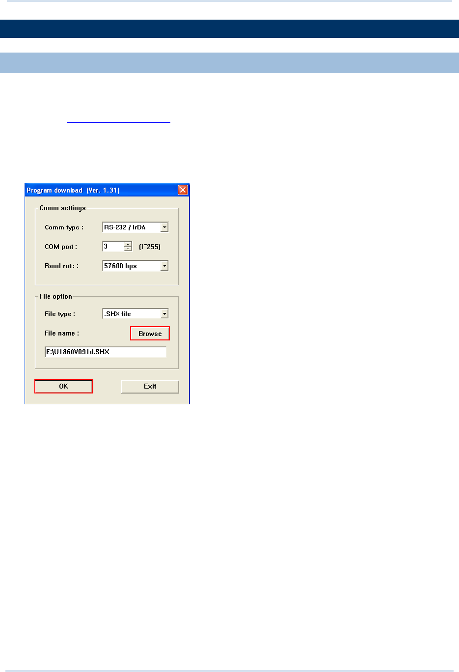
156
1800 Series Handheld RFID Reader Reference Manual
HOW TO UPGRADE FIRMWARE
USE USB VIRTUAL COM
1) Use the provided USB cable to connect RFID Reader to the USB port of host computer.
You will need to install USB cable driver first.
2) Refer to Using HyperTerminal for connecting with USB cable.
3) Issue “#@sys_dlfw=0” or “#@sys_dlfw=2”command.
4) End HyperTerminal.
5) Run the download utility “ProgLoad.exe” on the host computer.
For the communication settings, select
“RS-232/IrDA” and the correct COM port for
Direct USB Virtual COM interface.
Ignore the baud rate setting.
For the file option, click [Browse] to select
the target file e.g. U1860V*.SHX for
firmware update.
Click [OK].
6) After upgrading, RFID Reader will restart automatically.

157
Appendix I Firmware Upgrade
USE BLUETOOTH® DONGLE
Please refer to 3.1.3 Bluetooth® HID and SPP Slave for the connection with Bluetooth®
dongle, and go through steps 3 (run “#@sys_dlfw=0” or “#@sys_dlfw=1” command) to
6 described in the Use USB Virtual COM section.
USE 3610
Please refer to 3.2 Connecting via 3610 for connecting to 3610, and go through steps 3
(run “#@sys_dlfw=0” or “#@sys_dlfw=1” command) to 6 described in the Use USB
Virtual COM section.
Note: Please upgrade firmware to one RFID reader at a time, while using Bluetooth®
connection. For example, turn off each of the rest RFID readers when there is
more than one RFID reader connected to host computer.
USE <F2>+<TRIGGER>
1) Power Off RFID Reader.
2) Press and hold the <F2>+<Trigger> for 3 seconds to enter Firmware Upgrade mode.
3) Use USB cable to connect RFID Reader and host computer.
4) Run the download utility “ProgLoad.exe” on host computer to upgrade the firmware.
Note: <F2>+<Trigger> firmware upgrade only supports Windows CDC Virtual COM
driver. Please refer to 2.1 USB Interface to configure USB type.

158
1800 Series Handheld RFID Reader Reference Manual

159
0 1 2 3 4 5 6 7
0 DLE SP 0 @ P ` p
1 SOH DC1 ! 1 A Q a q
2 STX DC2 " 2 B R b r
3 ETX DC3 # 3 C S c s
4 EOT DC4 $ 4 D T d t
5 ENQ NAK % 5 E U e u
6 ACK SYN & 6 F V f v
7 BEL ETB ' 7 G W g w
8 BS CAN ( 8 H X h x
9 HT EM ) 9 I Y i y
A LF SUB * : J Z j z
B VT ESC + ; K [ k {
C FF FS , < L \ l |
D CR GS - = M ] m }
E SO RS . > N ^ n ~
F SI US / ? O _ o DEL
Appendix II
ASCII TABLE

160
1800 Series Handheld RFID Reader Reference Manual

161
00 10 20 30 40 50 60 70 80 90 A0 B0 C0 D0 E0 F0
00 00 10 20 30 40 50 60 70 80 90 A0 B0 C0 D0 E0 F0
01 01 11 21 31 41 51 61 71 81 91 A1 B1 C1 D1 E1 F1
02 02 12 22 32 42 52 62 72 82 92 A2 B2 C2 D2 E2 F2
03 03 13 23 33 43 53 63 73 83 93 A3 B3 C3 D3 E3 F3
04 04 14 24 34 44 54 64 74 84 94 A4 B4 C4 D4 E4 F4
05 05 15 25 35 45 55 65 75 85 95 A5 B5 C5 D5 E5 F5
06 06 16 26 36 46 56 66 76 86 96 A6 B6 C6 D6 E6 F6
07 07 17 27 37 47 57 67 77 87 97 A7 B7 C7 D7 E7 F7
08 08 18 28 38 48 58 68 78 88 98 A8 B8 C8 D8 E8 F8
09 09 19 29 39 49 59 69 79 89 99 A9 B9 C9 D9 E9 F9
0A 0A 1A 2A 3A 4A 5A 6A 7A 8A 9A AA BA CA DA EA FA
0B 0B 1B 2B 3B 4B 5B 6B 7B 8B 9B AB BB CB DB EB FB
0C 0C 1C 2C 3C 4C 5C 6C 7C 8C 9C AC BC CC DC EC FC
0D 0D 1D 2D 3D 4D 5D 6D 7D 8D 9D AD BD CD DD ED FD
0E 0E 1E 2E 3E 4E 5E 6E 7E 8E 9E AE BE CE DE EE FE
0F 0F 1F 2F 3F 4F 5F 6F 7F 8F 9F AF BF CF DF EF FF
Appendix III
SCAN CODE

162
1800 Series Handheld RFID Reader Reference Manual

163
value Meaning
0x00 OK
0x01 Host Mode operation finishes
0x02 Host Mode Inventory/Read/Write/Kill/Lock operation stops due to timeout or
excessive retry count
0x03 Reports the tag is locked in response to the host access command
0x04 End of Transmit in uploading Transmit buffer data or Memory mode data
0xDD Fail to configure the parameter of USB HID via 3610
0xDE Incorrect Bluetooth® type
(The parameter of Bluetooth® type is not consistent with connected device.)
0xDF Fail to set system time
(Real Time Clock cannot be configured.)
0xED Unsupported UHF command (UHF module firmware needs to be upgraded)
0xEE Conflict in Scan Mode and RFID Function
(Write Tag Memory function is not available in Continuous and Test Modes.)
0xEF RFID Fail
(Unable to configure RFID module upon Q value and Module Power Level
Command configurations.)
0xFA Invalid transmit buffer setting
0xFB The last operation is still running
0xFC Invalid mode (sending Host commands in Normal mode)
0xFD Invalid parameter in the Data field
0xFE Incorrect packet length
0xFF Invalid command or parameters
Appendix IV
STATUS CODE