CipherLab 5100125 Security Controller User Manual 5000 5100 Manual v1 by Herbie
CipherLab Co., Ltd. Security Controller 5000 5100 Manual v1 by Herbie
UserManual.wiki
>
CipherLab
>
5100125 User Manual
Users Manual
Navigation menu
Upload a User Manual
Namespaces
Wiki Guide
HTML
PDF
Info
Views
User Manual
Discussion / Help
Navigation
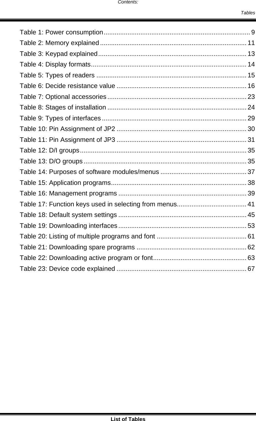
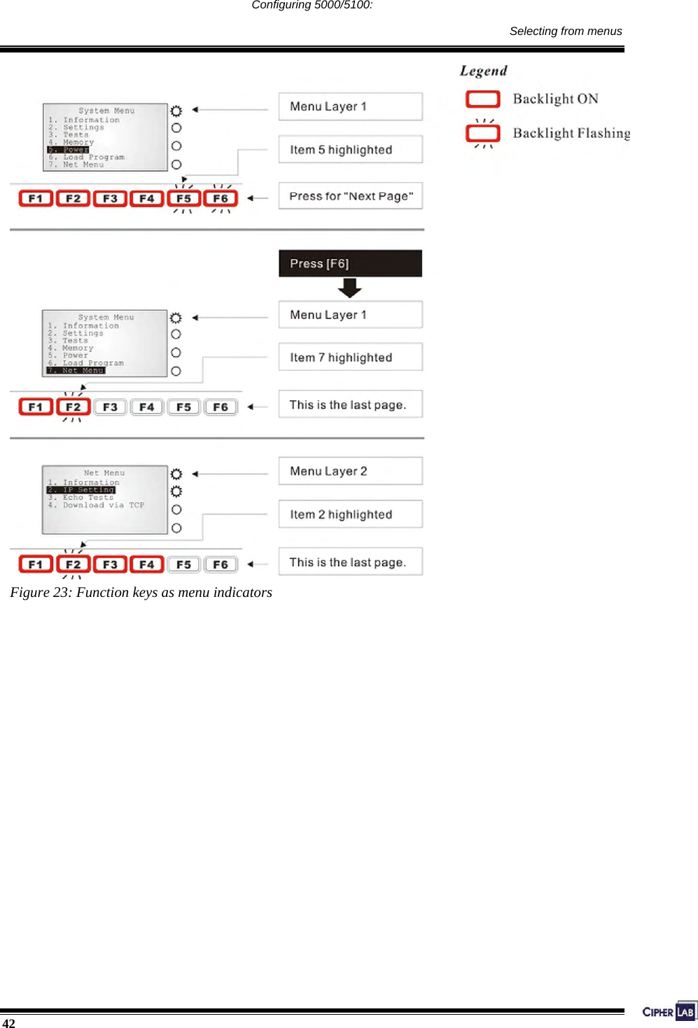
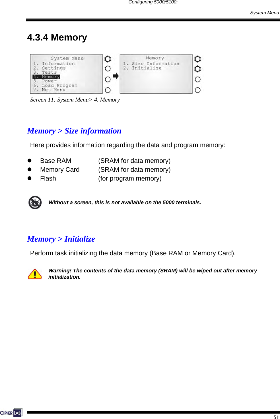
![41 Configuring 5000/5100: Selecting from menus 4.2 Selecting from menus The function keys can also be used in selecting item from menus on the screen. z To select item 1 to 5 on any menu, simply press [F1] to [F5]. z To select item 6 on any menu, press [F6] then [F1]. z To select item 7 on any menu, press [F6] then [F2]. F1 = 1 + [Enter] F2 = 2 + [Enter] F3 = 3 + [Enter] F4 = 4 + [Enter] F5 = 5 + [Enter] F6 = Next page F6 followed by F1 = 6 + [Enter] F6 followed by F2 = 7 + [Enter] Table 17: Function keys used in selecting from menus](https://usermanual.wiki/CipherLab/5100125/User-Guide-678244-Page-53.png)
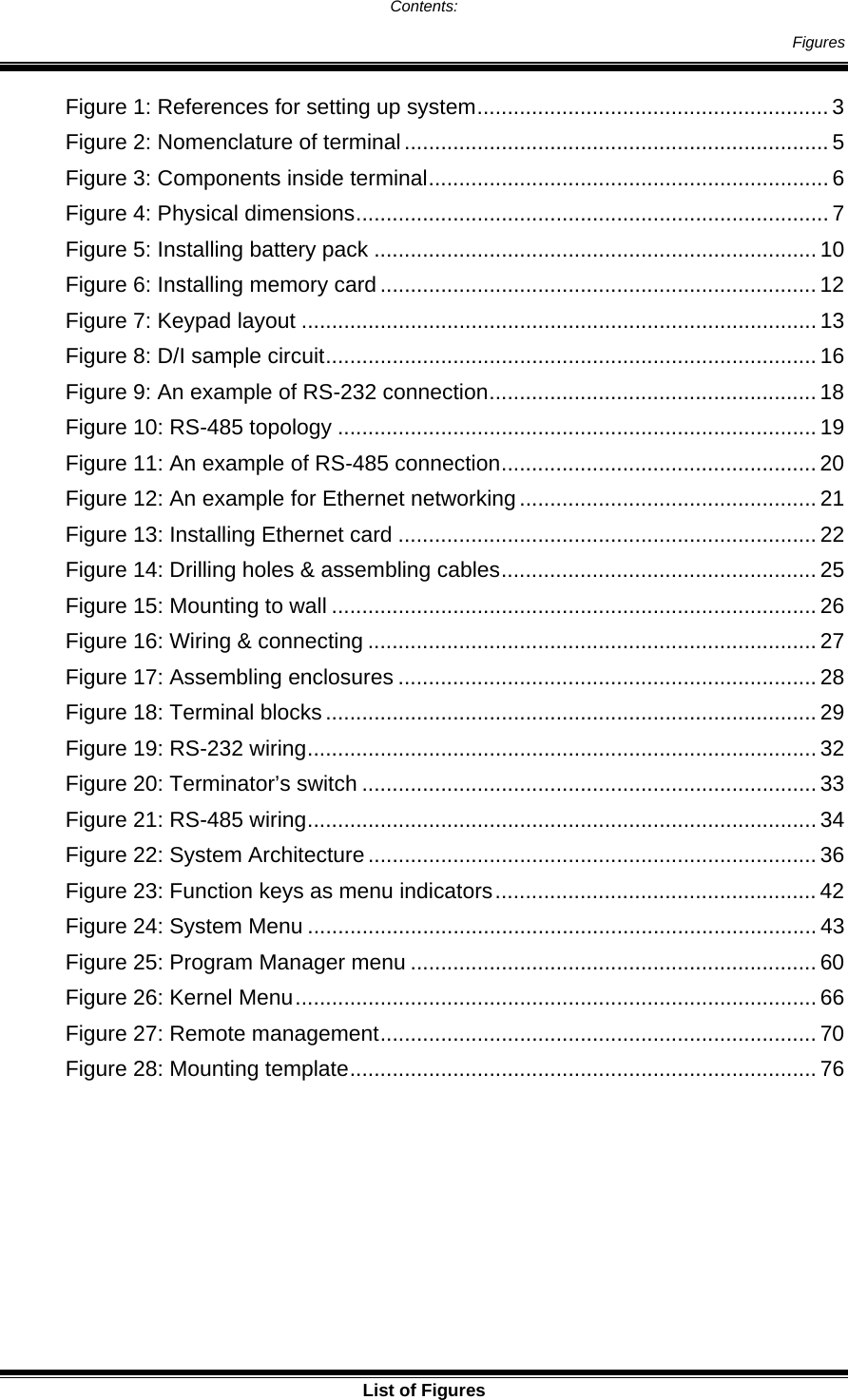
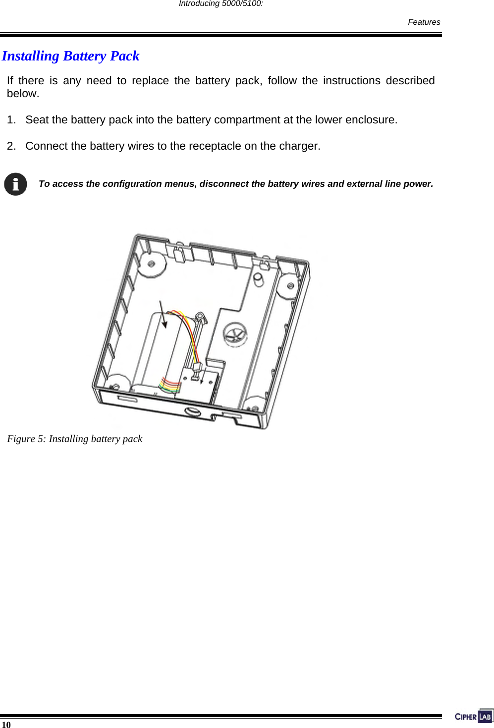
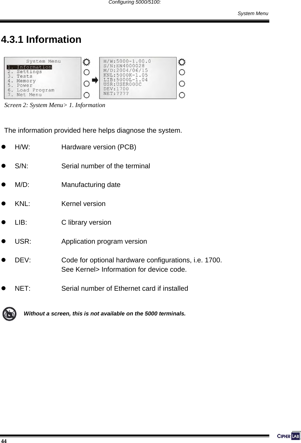
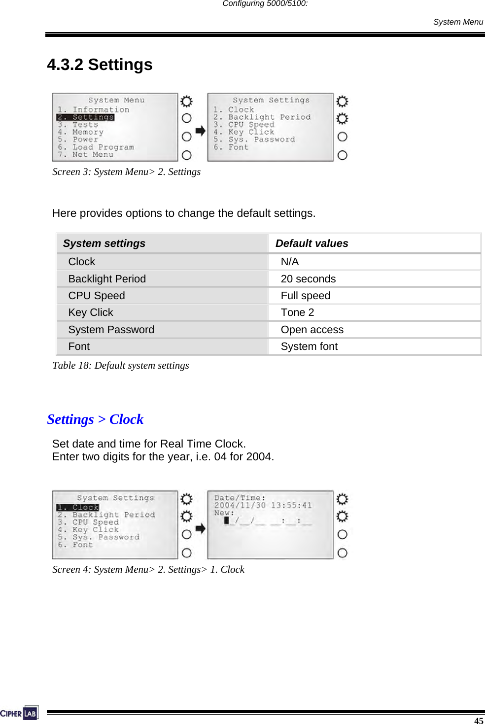
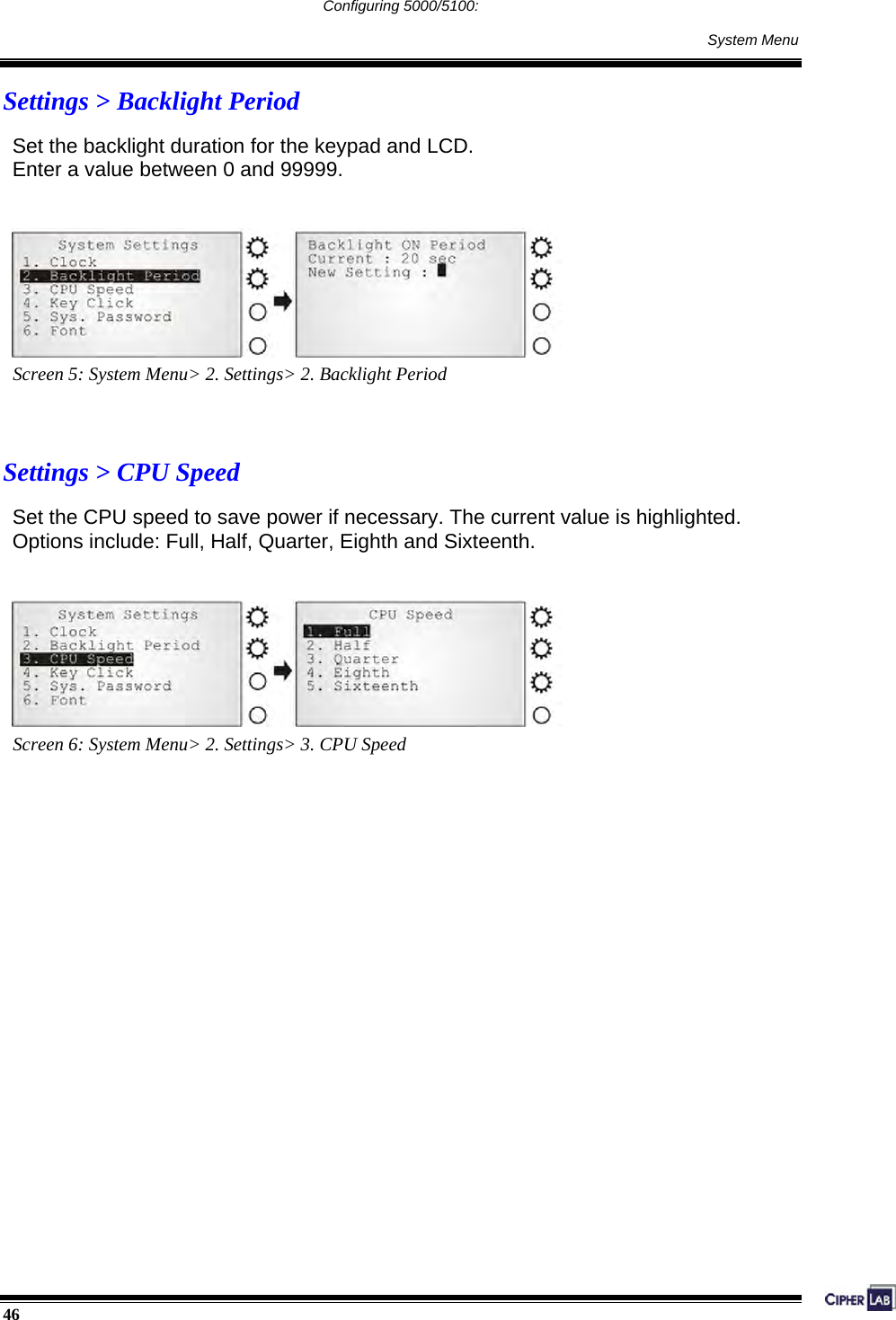
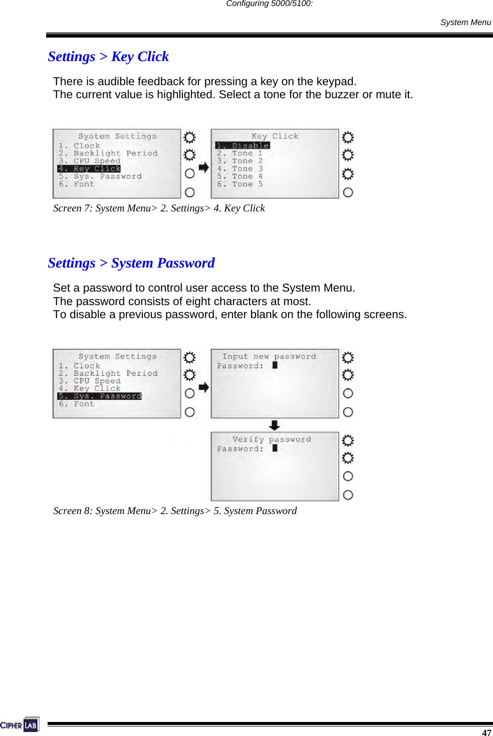
![43 Configuring 5000/5100: System Menu 4.3 System Menu The System Menu is generated by a powerful utility, which offers an interface for engineers (programmers or system integrator) to view system information, change the configuration parameters, manage files and run diagnostics. This menu is designed for engineering tests and maintenance ONLY. For this reason, the System Menu provides password protection to prevent unauthorized users from accidentally changing system settings. Warning! The System Menu is NOT for the use of any end users. The system password helps ensure system safety and integrity. How to access the System Menu? 1. Lift the upper enclosure by unscrewing the two screws on top of the terminal. 2. Disconnect BOTH the line power and main battery. 3. Re-connect the main battery and simultaneously press [5] + [7] + [9] from the keyboard. 4. The System Menu is displayed on the LCD screen as shown below. 5. Re-connect the line power when configuration is done. * Net Menu is available only when Ethernet card is present. Figure 24: System Menu](https://usermanual.wiki/CipherLab/5100125/User-Guide-678244-Page-55.png)
![48 Configuring 5000/5100: System Menu Settings > Font Current font information can be viewed here. z Default: System font z Custom font file, if there is one The font settings here can be changed if a multi-languages font file has been downloaded. (Press [2] / [8] to move down / up the menu of options.) Screen 9: System Menu> 2. Settings> 6. Font Without a screen, this is not available on the 5000 terminals.](https://usermanual.wiki/CipherLab/5100125/User-Guide-678244-Page-60.png)
![49 Configuring 5000/5100: System Menu 4.3.3 Tests Screen 10: System Menu> 3. Tests Here provides functional tests for key parts: Tests > Memory Test the data memory (SRAM), and the results will be shown on the screen. Press any key to exit. Without a screen, this is not available on the 5000 terminals. Warning! The contents of the data memory (SRAM) will be wiped out after test. Tests > Buzzer Test the buzzer with different frequency/duration combinations. Press [Enter] to start. Press any key to stop and exit the test.](https://usermanual.wiki/CipherLab/5100125/User-Guide-678244-Page-61.png)
![50 Configuring 5000/5100: System Menu Tests > LCD & LED Test the LCD display and LED indicator. Press [Enter] to start. Press any key to stop and exit the test. You may only be able to test the LED indicators on the 5000 terminals. Tests > Keyboard Test the rubber keys. Press any key and its corresponding character will be shown on the screen. Press [ESC] to stop and exit the test. Without a screen, this is not available on the 5000 terminals. Tests > RFID Test the reading performance of the RFID reader when a proximity card is present. Press [ESC] to stop and exit the test. Without a screen, this is not available on the 5000 terminals.](https://usermanual.wiki/CipherLab/5100125/User-Guide-678244-Page-62.png)
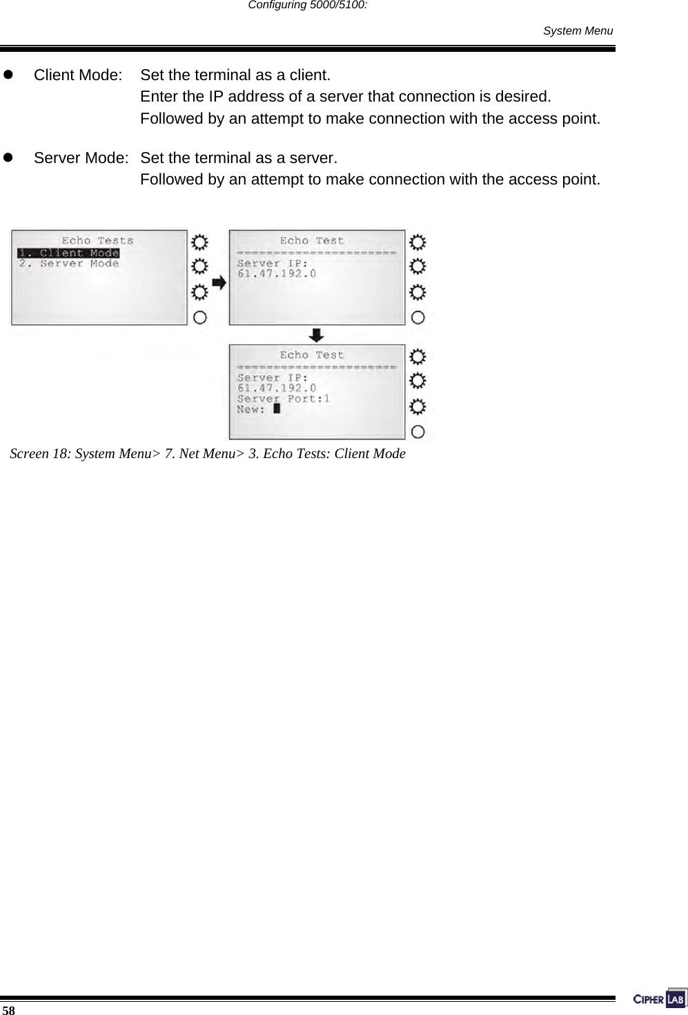
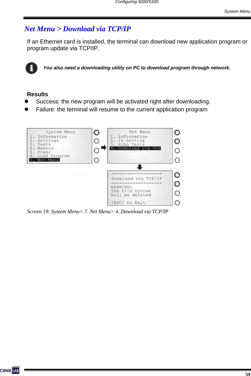
![57 Configuring 5000/5100: System Menu Net Menu > Echo Tests Echo tests are used for verify connectivity. Press [ESC] to stop and exit the test. You also need a test utility on PC to test the networking. Screen 17: System Menu> 7. Net Menu> 3. Echo Tests](https://usermanual.wiki/CipherLab/5100125/User-Guide-678244-Page-69.png)
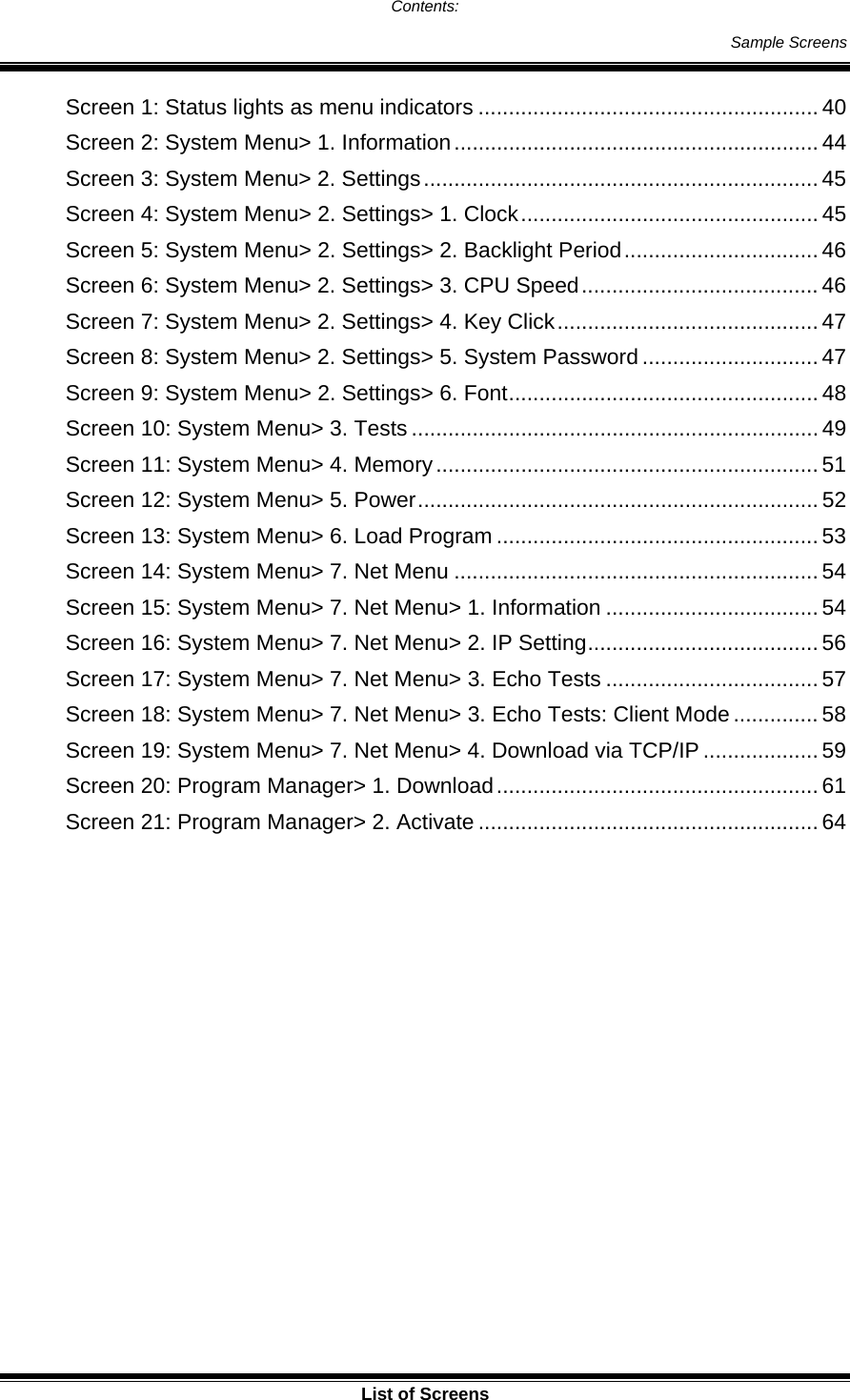
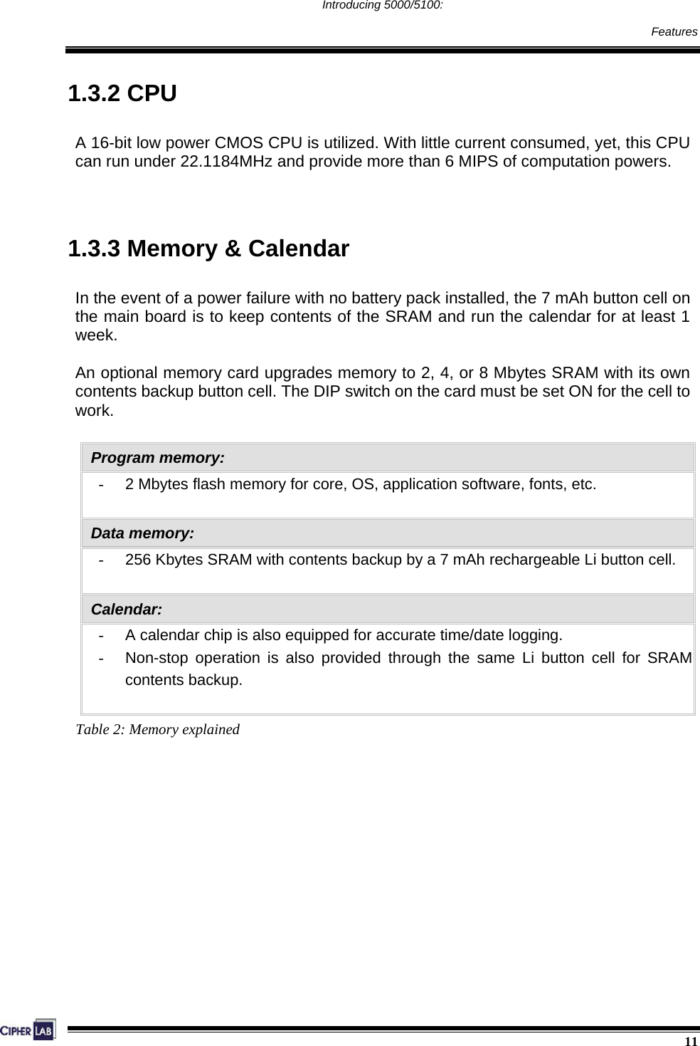
![60 Configuring 5000/5100: Program Manager 4.4 Program Manager The 5000/5100 terminals support multiple applications and languages. In the menu of Program Manager, it can download up to seven programs and one of them is made active. Warning! The Program Manager menu is NOT for the use of any end users. How to access the Program Manager? 1. Lift the upper enclosure by unscrewing the two screws on top of the terminal. 2. Disconnect BOTH the line power and main battery. 3. Re-connect the main battery and simultaneously press [5] + [8] from the keyboard. 4. The Program Manager menu is displayed on the LCD screen as shown below. 5. Re-connect the line power when configuration is done. Figure 25: Program Manager menu Program Manager Menu, which is generated by 51pm.shx, is unavailable by default. Please download 51pm.shx in the System Manu first.](https://usermanual.wiki/CipherLab/5100125/User-Guide-678244-Page-72.png)
![61 Configuring 5000/5100: Program Manager 4.4.1 Download Screen 20: Program Manager> 1. Download Multiple programs as well as custom font file can be downloaded through RS-232 interface. There is a full list of programs and font file that are currently stored in the terminal as follows. 01 ~ 06 File Name Volume Press [1 ~ 6] + [Enter] ACT File Name Volume [7] + [Enter] or [F6] + [F2] Table 20: Listing of multiple programs and font The terminal can store up to seven programs (including the one in active memory) and one font file (may not be shown in this list). z Spare application programs (max. 6): baud rate selectable z Active application program (1): default baud rate 115200, none, 8, 1 z Font file (1): default baud rate 115200, none, 8, 1 A slot number followed by “c”: the program is written by C language. A slot number followed by “f”: this is a font file. Only RS-232 interface is allowed.](https://usermanual.wiki/CipherLab/5100125/User-Guide-678244-Page-73.png)
![62 Configuring 5000/5100: Program Manager Spare application programs Empty slot: 1. Select an empty slot by pressing the corresponding number and then [Enter]. 2. Select baud rate for downloading. Set matching parameters at PC end. 3. Connect cable and wait connecting… 4. To abort the action, press [ESC]. Then press [ESC] again to return to the menu. Occupied slot: If no available slots, you’ll have to replace one program with the new one. 1. Select a program that you want to delete by pressing the corresponding number and then [Enter]. 2. The program information is displayed on the screen. Press [Alpha] to enter the capital mode. Then press [C]. 3. Select baud rate for downloading. Set matching parameters at PC end. 4. Connect cable and wait connecting… 5. To abort the action, press [ESC]. Then press [ESC] again to return to the menu. From the menu, you’ll find the program is deleted but no new program is present. If you simply want to delete a program, press [D] in step 2. Table 21: Downloading spare programs [C], [D]: press the keypad to produce C or D when in the capital mode A.](https://usermanual.wiki/CipherLab/5100125/User-Guide-678244-Page-74.png)
![63 Configuring 5000/5100: Program Manager Active application program or font file The active slot: 1. Select the active program (may be an empty slot) by pressing the corresponding number (that is 7) and then [Enter]. 2. Set matching parameters at PC end: 115200, none, 8, 1 3. Connect cable and wait connecting… 4. If the downloaded program is an application, it will replace the active program and come into effect immediately. 5. If it is a font file, then the current active program is still in use. Table 22: Downloading active program or font No font file will replace the active application program. The new font file may not be shown in the program list if all slots are taken by application programs, but you can view font information under System Menu> Settings> Font. >> Also see Section 4.3.2 Settings](https://usermanual.wiki/CipherLab/5100125/User-Guide-678244-Page-75.png)
![64 Configuring 5000/5100: Program Manager 4.4.2 Activate Screen 21: Program Manager> 2. Activate The list shows the entire spare programs stored in the terminal. From the list, you can select from 01 to 06 and activate one of them. z When an application program is activated, it will be copied to the active memory and replace the old one. The <New Program Start> screen instructs that “Press [ESC] to clear file”. It means the file system in the SRAM will be cleared out when pressing [ESC]. Then there will be no data (transactions, settings, etc.) stored in the terminal when the new program comes into effect. To keep the data, simply press any other key. z When a font file is activated, it will replace the system font. The active application program will remain intact.](https://usermanual.wiki/CipherLab/5100125/User-Guide-678244-Page-76.png)
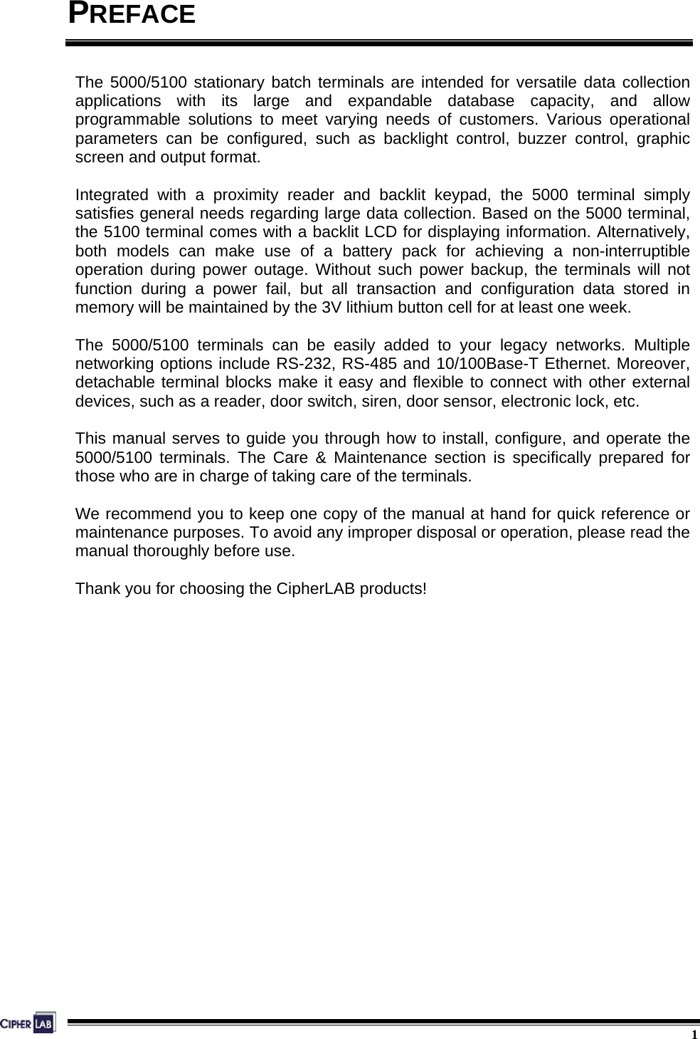
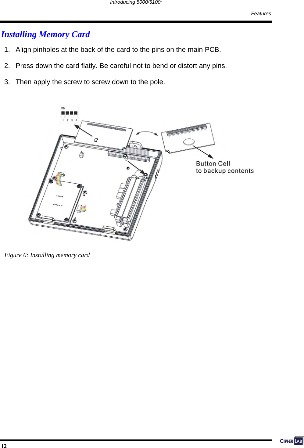
![66 Configuring 5000/5100: Kernel Menu 4.5 Kernel Menu The Kernel Menu resides in the innermost core of the system. It has the highest security and is always protected by the system. When the application program is corrupted and the System Menu fails, the Kernel Menu provides an access to fix the system. Warning! The Kernel Menu is NOT for the use of any end users. How to access the Kernel Menu? 1. Lift the upper enclosure by unscrewing the two screws on top of the terminal. 2. Disconnect BOTH the line power and main battery. 3. Re-connect the main battery and simultaneously press [1] + [5] + [7] from the keyboard. 4. The Kernel Menu is displayed on the LCD screen as shown below. 5. Re-connect the line power when configuration is done. Figure 26: Kernel Menu](https://usermanual.wiki/CipherLab/5100125/User-Guide-678244-Page-78.png)
![Net Menu Re-connect the main battery and simultaneously press [5] + [7] + [9] from the keyboard. Press [7] into Net Manu This submenu is for IEEE 802.11b wireless networking. Parameters must be configured correctly. Note: This menu is available only when the 802.11b module is installed. 802.11b Menu: Settings: Default Values DHCP Enable SubNet Mask 255.255.128.0 Local IP Address 0.0.0.0 Default Gateway 0.0.0.0 DNS Server 0.0.0.0 IP Setting Domain Name blank Local Name blank Domain Name blank SS ID blank System Scale Medium Power Saving Enable WLAN Setting Preamble Long Authentication Open System WEP Menu Disable Security EAP Menu Disable](https://usermanual.wiki/CipherLab/5100125/User-Guide-678244-Page-91.png)
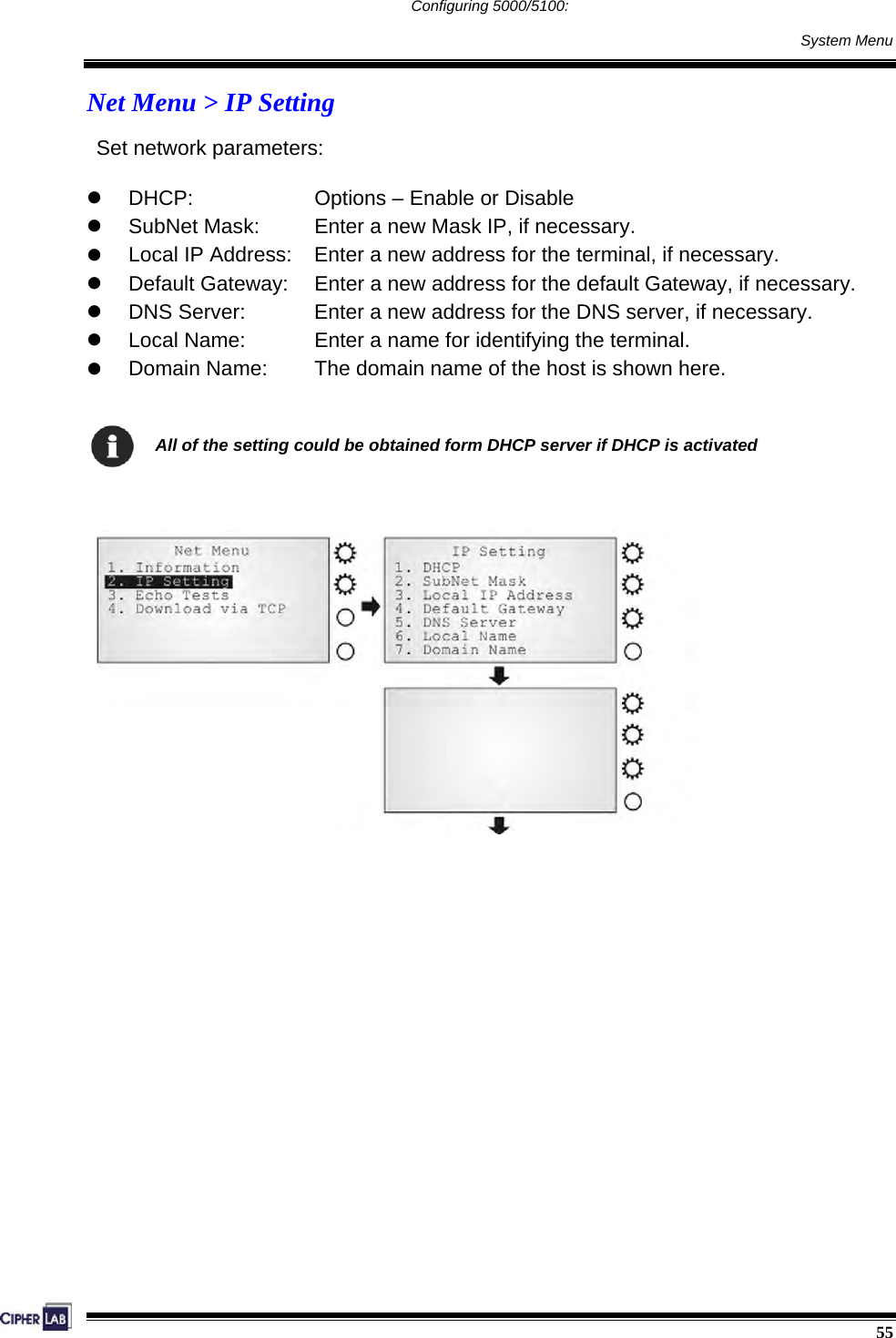
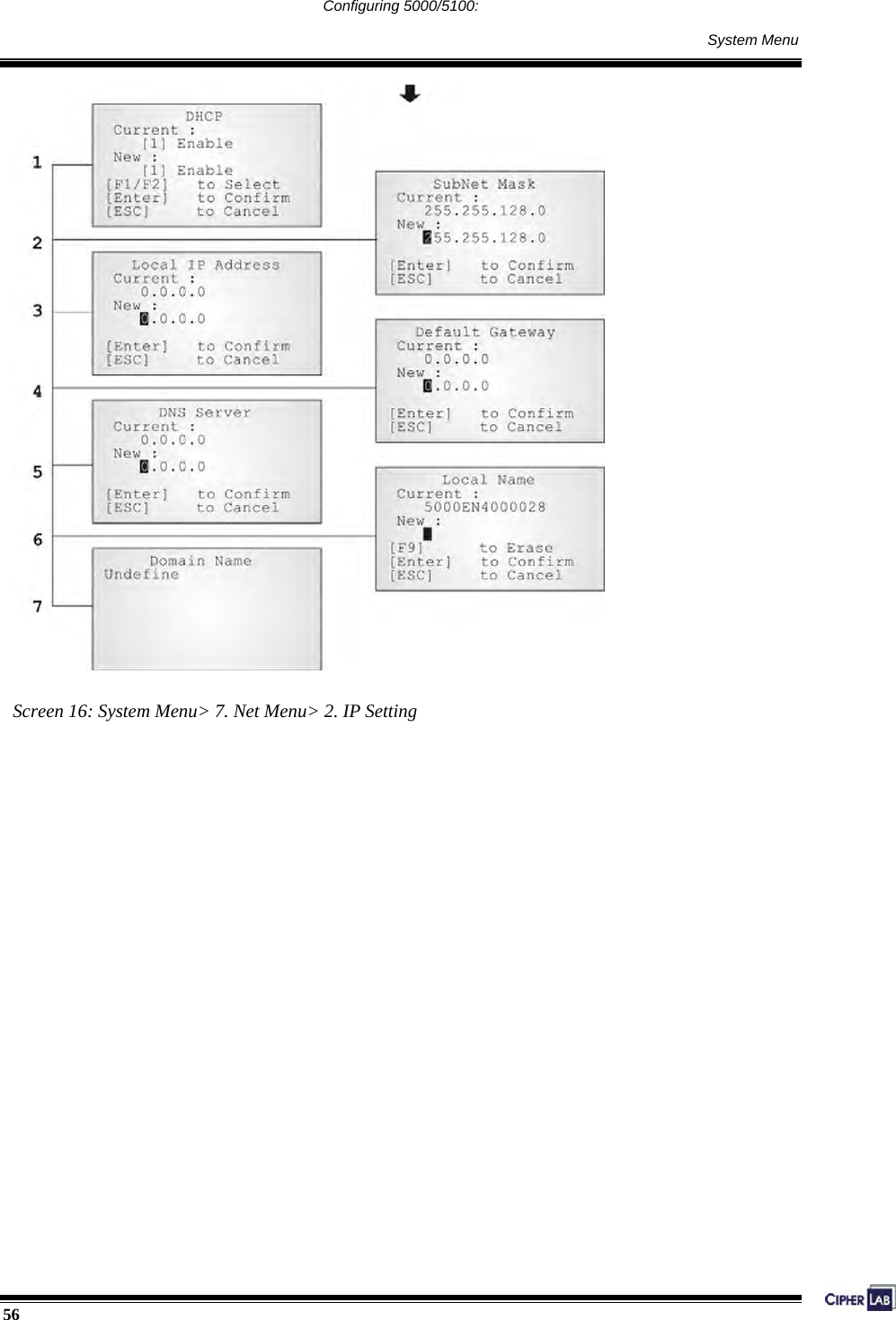
![¾ Net Menu > Information Information of network configuration can be viewed here. MAC: MAC ID of the 802.11b module DHCP: DHCP being enabled or disabled IP: IP address of the terminal Mask: Subnet Mask Gate: Default Gateway ¾ Net Menu > IP Setting Set general network parameters. DHCP: Options - Enable or Disable SubNet Mask: Enter a new Mask IP, if necessary. Local IP Address: Enter a new address for the terminal, if necessary. Default Gateway: Enter a new address for the default Gateway, if necessary. DNS Server: Enter a new address for the DNS server, if necessary. Domain Name: The domain name of the host is shown here. Note: All of the setting could be obtained form DHCP server if DHCP is activated. ¾ Net Menu > WLAN Setting 802.11b system can operate in two modes (1) Ad-hoc mode: peer-to-peer, and (2) Infrastructure mode: point to multi-point through access points. Set the following parameters. Local Name: Enter a name for identifying the terminal. Domain Name: The domain name of the host is shown here. SS ID: This refers to Service Set ID or Identifier. The terminal can ONLY communicate with access points that have the same SS ID System Scale: This refers to Access Point Density. Options - [1] Low [2] Medium [3] High](https://usermanual.wiki/CipherLab/5100125/User-Guide-678244-Page-92.png)
![The value you set must match that set for the access point. Power Saving: This refers to the low power consumption mode. Options - Enable or Disable The value you set must match that set for the access point. Preamble: Options - [1] Long [2] Short [3] Both The value you set must match that set for the access point. ¾ Net Menu > Security Set up or modify security parameters: Authentication [1] Open System: [0] Share Key: Default authentication type This requires implementing WEP key.](https://usermanual.wiki/CipherLab/5100125/User-Guide-678244-Page-93.png)