CipherLab 5100125 Security Controller User Manual 5000 5100 Manual v1 by Herbie
CipherLab Co., Ltd. Security Controller 5000 5100 Manual v1 by Herbie
Users Manual
5000/5100
Reference Manual
Version 1.02
Jun. 16, 06

STATEMENTS
Copyright
© CipherLab Co., Ltd. 2004 All rights reserved.
This document, as well as any software included, may not be reproduced, stored in
retrieval system or transmitted, in any form or by any means, without prior written
consent of the copyright owners.
Trademark
The logo is a registered trademark of CipherLab Co., Ltd.
Disclaimer of Liability
Efforts have been made to ensure the accuracy of the information presented in this
document. In the interest of improving internal design, operational function, and/or
reliability, CipherLab reserves the right to make changes to the products described in
this document without prior notice. CipherLab does not assume any liability that may
occur due to the use or application of the product(s) or circuit layout(s) described
herein.
Technical Support
For product consultancy and technical questions, please contact your local sales
representative. For more information, please visit our website.
http://www.cipherlab.com

ii
Statements: FCC Regulations & Technical Standards
FCC Regulations:
zThis device complies with part 15 of the FCC Rules. Operation is subject to the following two
conditions: (1) This device may not cause harmful interference, and (2) this device must accept any
interference received, including interference that may cause undesired operation.
zThis device has been tested and found to comply with the limits for a Class B digital device, pursuant to
Part 15 of the FCC Rules. These limits are designed to provide reasonable protection against harmful
interference in a residential installation. This equipment generates, uses and can radiated radio
frequency energy and, if not installed and used in accordance with the instructions, may cause harmful
interference to radio communications. However, there is no guarantee that interference will not occur in
a particular installation If this equipment does cause harmful interference to radio or television reception,
which can be determined by turning the equipment off and on, the user is encouraged to try to correct
the interference by one or more of the following measures:
-Reorient or relocate the receiving antenna.
-Increase the separation between the equipment and receiver.
-Connect the equipment into an outlet on a circuit different from that to which the receiver is connected.
-Consult the dealer or an experienced radio/TV technician for help.
Changes or modifications not expressly approved by the party responsible for compliance could void the
user‘s authority to operate the equipment.
CAUTION :
1. For AC power adapter
Pluggable equipment, the socket-outlet shall be installed near the equipment and shall be easily
accessible. Indicate power adaptor should be complied with L.P.S test.
2. For Battery Pack
RISK OF EXPLOSION IF BATTERY IS REPLACED BY AN INCORRECT TYPE.
DISPOSE OF USED BATTERIES ACCORDING TO THE INSTRUCTIONS
(※ Battery disposal For green-environment issue it's important that batteries should be recycled in a proper
way.)
3.Any changes or modifications not expressly approved by the party responsible for compliance could void
the user's authority to operate this equipment.
4.This transmitter must not be co-located or operating in conjunction with any other antenna or transmitter.
低功率電波輻射性電機管理辦法 ( For Taiwan )
第十二條 經型式認證合格之低功率射頻電機,非經許可,公司、商號或使用者不得擅自
變更頻率、加大功率或變更原設計之特性及功能。
第十四條 低功率射頻電機之使用不得影響飛航安全及干擾合法通信;經發現有干擾現象
時,應立即停用,並改善至吳干擾時方得繼續使用。
前項合法通信,指依電信法規定作業之無線電通信。
低功率射頻電機需忍受合法通信或工業、科學及醫療用電波輻射性電機設備之干擾。
IMPORTANT NOTE: FCC Radiation Exposure Statement:
This equipment complies with FCC radiation exposure limits set forth for an uncontrolled environment.

Statements
CONTENTS
REVISION HISTORY....................................................錯誤! 尚未定義書籤。
PREFACE ...................................................................................................1
CARE & MAINTENANCE ..............................................................................2
GETTING READY ........................................................................................3
1. INTRODUCING 5000/5100.......................................................................4
1.1 Product Highlights ............................................................................................. 4
1.2 Nomenclature...................................................................................................... 5
1.2.1 Inside Enclosures........................................................................................ 6
1.2.2 Dimensions.................................................................................................. 7
1.3 Features .............................................................................................................. 8
1.3.1 Power .......................................................................................................... 8
1.3.2 CPU........................................................................................................... 11
1.3.3 Memory & Calendar .................................................................................. 11
1.3.4 Keyboard................................................................................................... 13
1.3.5 LCD ........................................................................................................... 14
1.3.6 Status LEDs ..............................................................................................15
1.3.7 Buzzer ....................................................................................................... 15
1.3.8 Readers..................................................................................................... 15
1.3.9 Digital Inputs.............................................................................................. 16
1.3.10 Digital Outputs......................................................................................... 17
1.3.11 RS-232 .................................................................................................... 18
1.3.12 RS-485 .................................................................................................... 19
1.3.13 Ethernet................................................................................................... 21
1.3.14 Programming Support ............................................................................. 22
1.4 Unpacking the package .................................................................................... 23
1.5 Options .............................................................................................................. 23

Table of Contents
Contents:
Section 2 ~4.3
2. INSTALLING 5000/5100........................................................................24
2.1 Setting up the terminal ..................................................................................... 24
2.2 Wiring................................................................................................................ 29
2.2.1 Pin Assignments........................................................................................ 30
2.2.2 RS-232 ...................................................................................................... 32
2.2.3 RS-485 ...................................................................................................... 33
2.2.4 Digital Inputs/Outputs................................................................................ 35
3. SYSTEM ARCHITECTURE....................................................................... 36
3.1 Operation .......................................................................................................... 37
3.2 Download .......................................................................................................... 38
3.3 Management ..................................................................................................... 39
4. CONFIGURING 5000/5100 ....................................................................40
4.1 Identifying current menu ................................................................................. 40
4.2 Selecting from menus....................................................................................... 41
4.3 System Menu..................................................................................................... 43
4.3.1 Information ................................................................................................44
4.3.2 Settings ..................................................................................................... 45
4.3.3 Tests.......................................................................................................... 49
4.3.4 Memory .....................................................................................................51
4.3.5 Power ........................................................................................................ 52
4.3.6 Load Program............................................................................................ 53
4.3.7 NET Menu ................................................................................................. 54

Tables of Contents
Contents:
Section 4.4 ~
4.4 Program Manager ............................................................................................ 60
4.4.1 Download ..................................................................................................61
4.4.2 Activate...................................................................................................... 64
4.4.3 Version ...................................................................................................... 65
4.5 Kernel Menu ..................................................................................................... 66
4.5.1 Information ................................................................................................67
4.5.2 Load Program............................................................................................ 68
4.5.3 Kernel Update ...........................................................................................69
4.5.4 Test & Calibrate......................................................................................... 69
5. MANAGING 5000/5100.........................................................................70
5.1 For proprietary applications ............................................................................ 71
5.2 For custom applications................................................................................... 71
SPECIFICATIONS ......................................................................................72
TROUBLESHOOTING .................................................................................74
APPENDIX I – MOUNTING TEMPLATE .........................................................76

List of Tables
Contents:
Tables
Table 1: Power consumption................................................................................ 9
Table 2: Memory explained ................................................................................ 11
Table 3: Keypad explained................................................................................. 13
Table 4: Display formats..................................................................................... 14
Table 5: Types of readers ..................................................................................15
Table 6: Decide resistance value ....................................................................... 16
Table 7: Optional accessories............................................................................ 23
Table 8: Stages of installation ............................................................................ 24
Table 9: Types of interfaces............................................................................... 29
Table 10: Pin Assignment of JP2 ....................................................................... 30
Table 11: Pin Assignment of JP3 ....................................................................... 31
Table 12: D/I groups........................................................................................... 35
Table 13: D/O groups......................................................................................... 35
Table 14: Purposes of software modules/menus ............................................... 37
Table 15: Application programs.......................................................................... 38
Table 16: Management programs ...................................................................... 39
Table 17: Function keys used in selecting from menus...................................... 41
Table 18: Default system settings ...................................................................... 45
Table 19: Downloading interfaces...................................................................... 53
Table 20: Listing of multiple programs and font .................................................61
Table 21: Downloading spare programs ............................................................62
Table 22: Downloading active program or font................................................... 63
Table 23: Device code explained ....................................................................... 67

List of Figures
Contents:
Figures
Figure 1: References for setting up system.......................................................... 3
Figure 2: Nomenclature of terminal ...................................................................... 5
Figure 3: Components inside terminal.................................................................. 6
Figure 4: Physical dimensions.............................................................................. 7
Figure 5: Installing battery pack ......................................................................... 10
Figure 6: Installing memory card ........................................................................ 12
Figure 7: Keypad layout .....................................................................................13
Figure 8: D/I sample circuit................................................................................. 16
Figure 9: An example of RS-232 connection...................................................... 18
Figure 10: RS-485 topology ...............................................................................19
Figure 11: An example of RS-485 connection.................................................... 20
Figure 12: An example for Ethernet networking ................................................. 21
Figure 13: Installing Ethernet card ..................................................................... 22
Figure 14: Drilling holes & assembling cables.................................................... 25
Figure 15: Mounting to wall ................................................................................ 26
Figure 16: Wiring & connecting .......................................................................... 27
Figure 17: Assembling enclosures ..................................................................... 28
Figure 18: Terminal blocks................................................................................. 29
Figure 19: RS-232 wiring.................................................................................... 32
Figure 20: Terminator’s switch ........................................................................... 33
Figure 21: RS-485 wiring.................................................................................... 34
Figure 22: System Architecture .......................................................................... 36
Figure 23: Function keys as menu indicators..................................................... 42
Figure 24: System Menu .................................................................................... 43
Figure 25: Program Manager menu ................................................................... 60
Figure 26: Kernel Menu...................................................................................... 66
Figure 27: Remote management........................................................................ 70
Figure 28: Mounting template............................................................................. 76

List of Screens
Contents:
Sample Screens
Screen 1: Status lights as menu indicators ........................................................ 40
Screen 2: System Menu> 1. Information............................................................ 44
Screen 3: System Menu> 2. Settings................................................................. 45
Screen 4: System Menu> 2. Settings> 1. Clock................................................. 45
Screen 5: System Menu> 2. Settings> 2. Backlight Period................................ 46
Screen 6: System Menu> 2. Settings> 3. CPU Speed....................................... 46
Screen 7: System Menu> 2. Settings> 4. Key Click........................................... 47
Screen 8: System Menu> 2. Settings> 5. System Password ............................. 47
Screen 9: System Menu> 2. Settings> 6. Font................................................... 48
Screen 10: System Menu> 3. Tests ................................................................... 49
Screen 11: System Menu> 4. Memory............................................................... 51
Screen 12: System Menu> 5. Power.................................................................. 52
Screen 13: System Menu> 6. Load Program ..................................................... 53
Screen 14: System Menu> 7. Net Menu ............................................................ 54
Screen 15: System Menu> 7. Net Menu> 1. Information ................................... 54
Screen 16: System Menu> 7. Net Menu> 2. IP Setting...................................... 56
Screen 17: System Menu> 7. Net Menu> 3. Echo Tests ................................... 57
Screen 18: System Menu> 7. Net Menu> 3. Echo Tests: Client Mode .............. 58
Screen 19: System Menu> 7. Net Menu> 4. Download via TCP/IP ................... 59
Screen 20: Program Manager> 1. Download..................................................... 61
Screen 21: Program Manager> 2. Activate ........................................................ 64

1
PREFACE
The 5000/5100 stationary batch terminals are intended for versatile data collection
applications with its large and expandable database capacity, and allow
programmable solutions to meet varying needs of customers. Various operational
parameters can be configured, such as backlight control, buzzer control, graphic
screen and output format.
Integrated with a proximity reader and backlit keypad, the 5000 terminal simply
satisfies general needs regarding large data collection. Based on the 5000 terminal,
the 5100 terminal comes with a backlit LCD for displaying information. Alternatively,
both models can make use of a battery pack for achieving a non-interruptible
operation during power outage. Without such power backup, the terminals will not
function during a power fail, but all transaction and configuration data stored in
memory will be maintained by the 3V lithium button cell for at least one week.
The 5000/5100 terminals can be easily added to your legacy networks. Multiple
networking options include RS-232, RS-485 and 10/100Base-T Ethernet. Moreover,
detachable terminal blocks make it easy and flexible to connect with other external
devices, such as a reader, door switch, siren, door sensor, electronic lock, etc.
This manual serves to guide you through how to install, configure, and operate the
5000/5100 terminals. The Care & Maintenance section is specifically prepared for
those who are in charge of taking care of the terminals.
We recommend you to keep one copy of the manual at hand for quick reference or
maintenance purposes. To avoid any improper disposal or operation, please read the
manual thoroughly before use.
Thank you for choosing the CipherLAB products!

2
CARE & MAINTENANCE
This is specifically prepared for those who are in charge of taking care of the terminals,
such as a terminal operator or maintenance engineer.
Here are some tips on how to take care and maintain the terminals.
Taking care of the terminal
z Always keep electric equipments like the terminals away from any flammable
sources.
z Always make sure there is stable power supply for the terminal to operate
properly.
z This terminal is intended for indoor use. It may do damage to the terminals when
being exposed to extreme temperatures or soaked wet.
z When the body of the terminal gets dirty, use a clean and wet cloth to wipe off the
dust. DO NOT use/mix any bleach or cleaner. Always keep the LCD dry.
z For a liquid crystal display (LCD), DO NOT use any pointed or sharp objects to
move against the surface.
Maintaining the terminal
z If you want to put away the terminal for a period of time, download the collected
data to a host first, and then take out the battery pack. Store the terminal and
battery pack separately.
z When the terminal resumes its work, the rechargeable main and backup batteries
will take a certain time to become fully charged.
z If you shall find the terminal malfunctioning, refer to the Troubleshooting section
for self help first.
z If the problem persists, please write down the specific scenario and consult your
local sales representative.
z In no circumstances, users are allowed to repair components.
3
GETTING READY
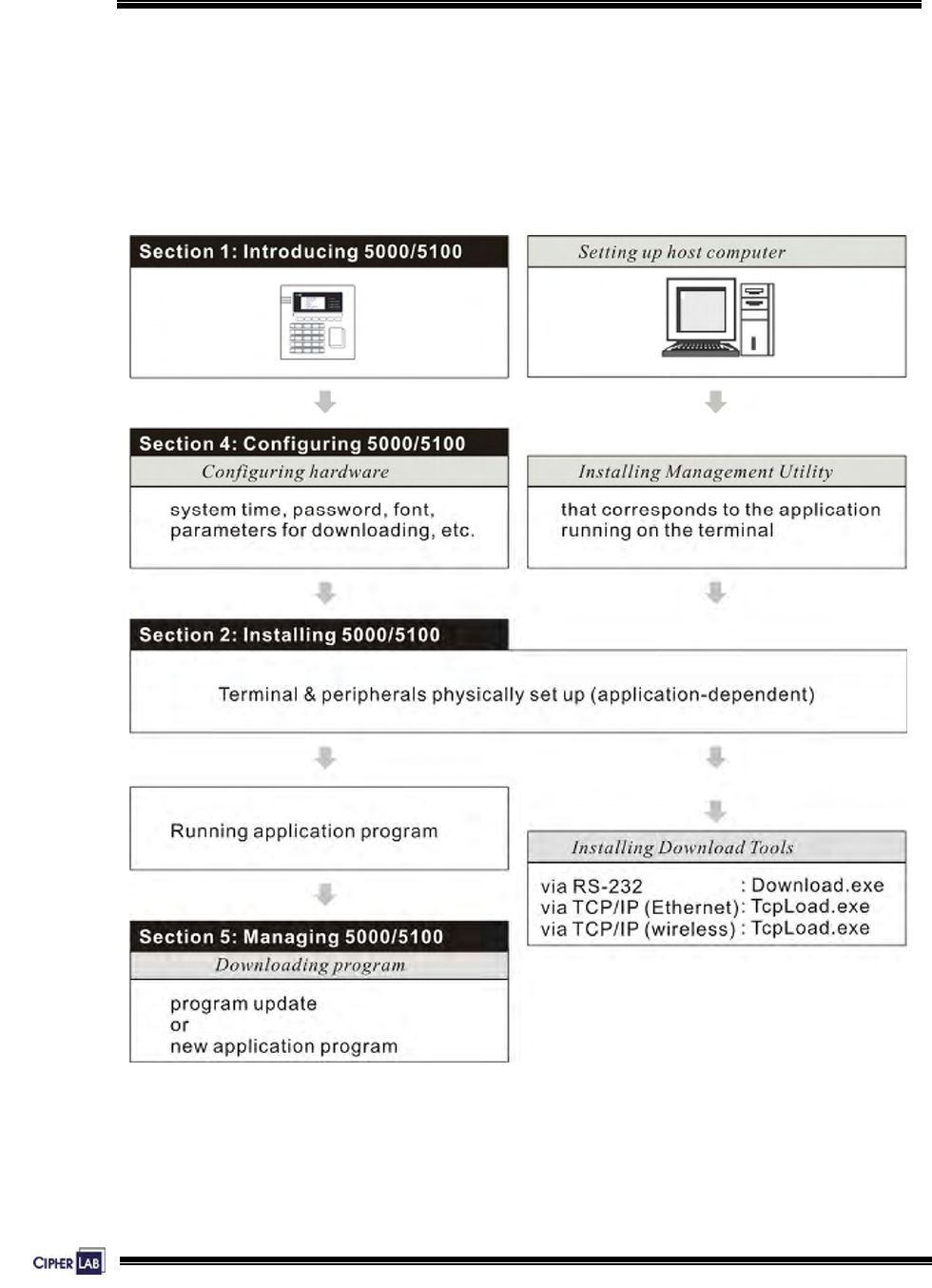
If you are using the terminal for the first time, the illustration below gives outline of the
system and section references.
Access to the configuration menus needs to disconnect the external and internal
power connection of the terminal first. Therefore, we suggest that you do all the
configuration and downloading jobs before setting up the system on site.
Figure 1: References for setting up system

4
1. INTRODUCING 5000/5100
This section mainly explains the hardware construction and features of the 5000/5100
terminals. The 5100 terminal looks similar to the 5000 terminal except for the screen.
1.1 Product Highlights
z 2, 4 or 8 MB for expandable data memory, powered by backup cell
z Graphic LCD supports double-byte languages
z Battery operated when AC power is interrupted (if the battery pack is installed)
z Tamper switch to activate the buzzer during removal of enclosures
z 4 Digital Input & 4 Digital Output for monitoring/controlling external devices
z Programmable signals to accommodate custom applications
z Programming support: OCX, BASIC and C
z OCX component supports TCP/IP, RS-232 and Modem communications
5
Introducing 5000/5100:
Nomenclature
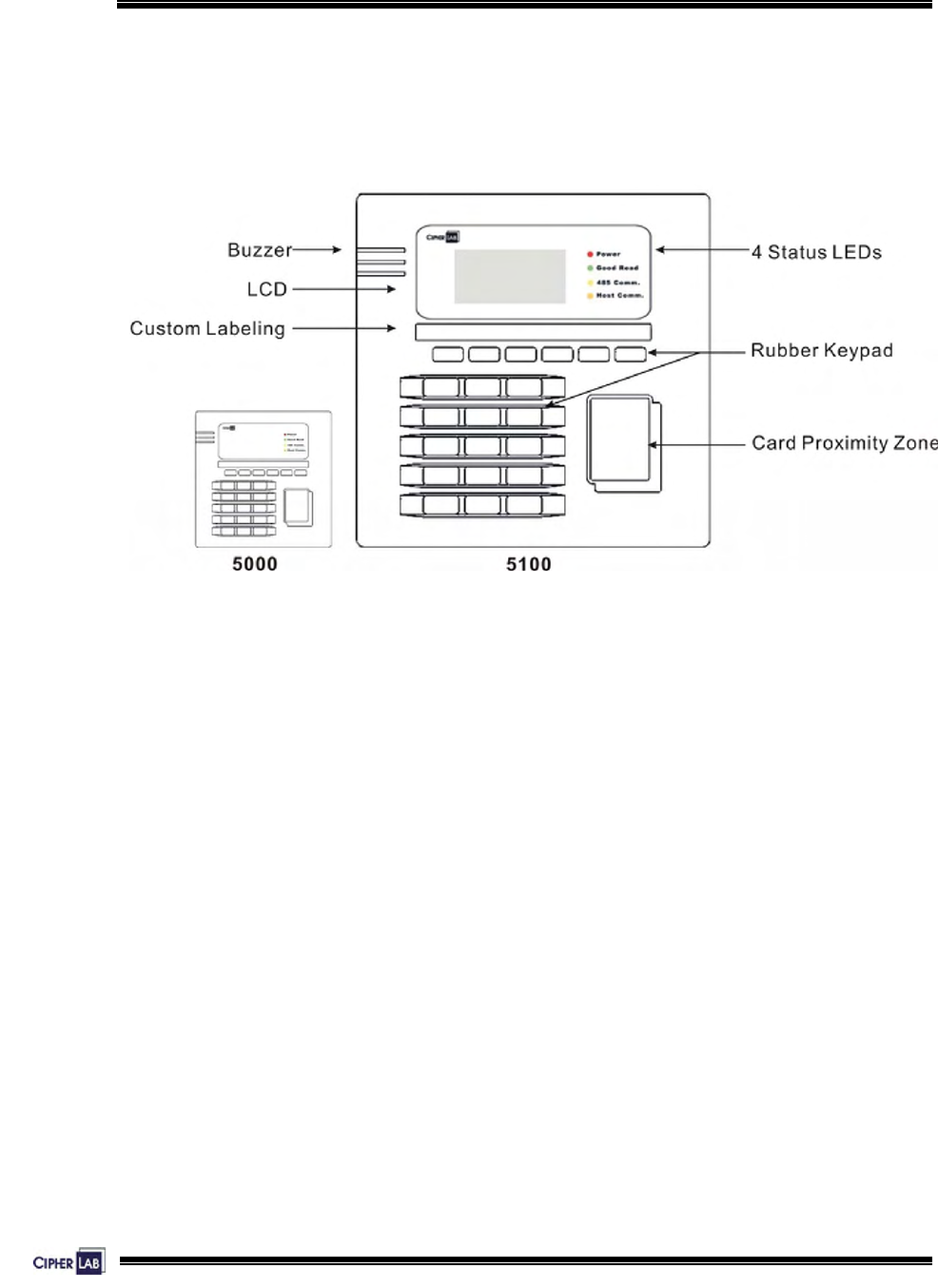
1.2 Nomenclature
The pictures below show the major components:
Figure 2: Nomenclature of terminal
6
Introducing 5000/5100:
Nomenclature
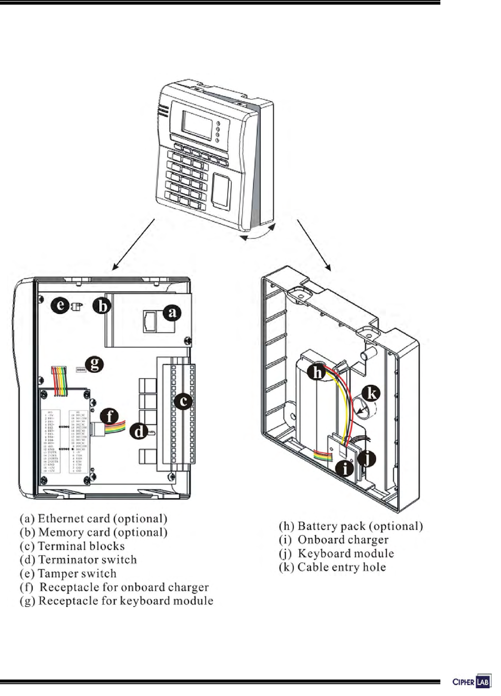
1.2.1 Inside Enclosures
Figure 3: Components inside terminal
7
Introducing 5000/5100:
Nomenclature
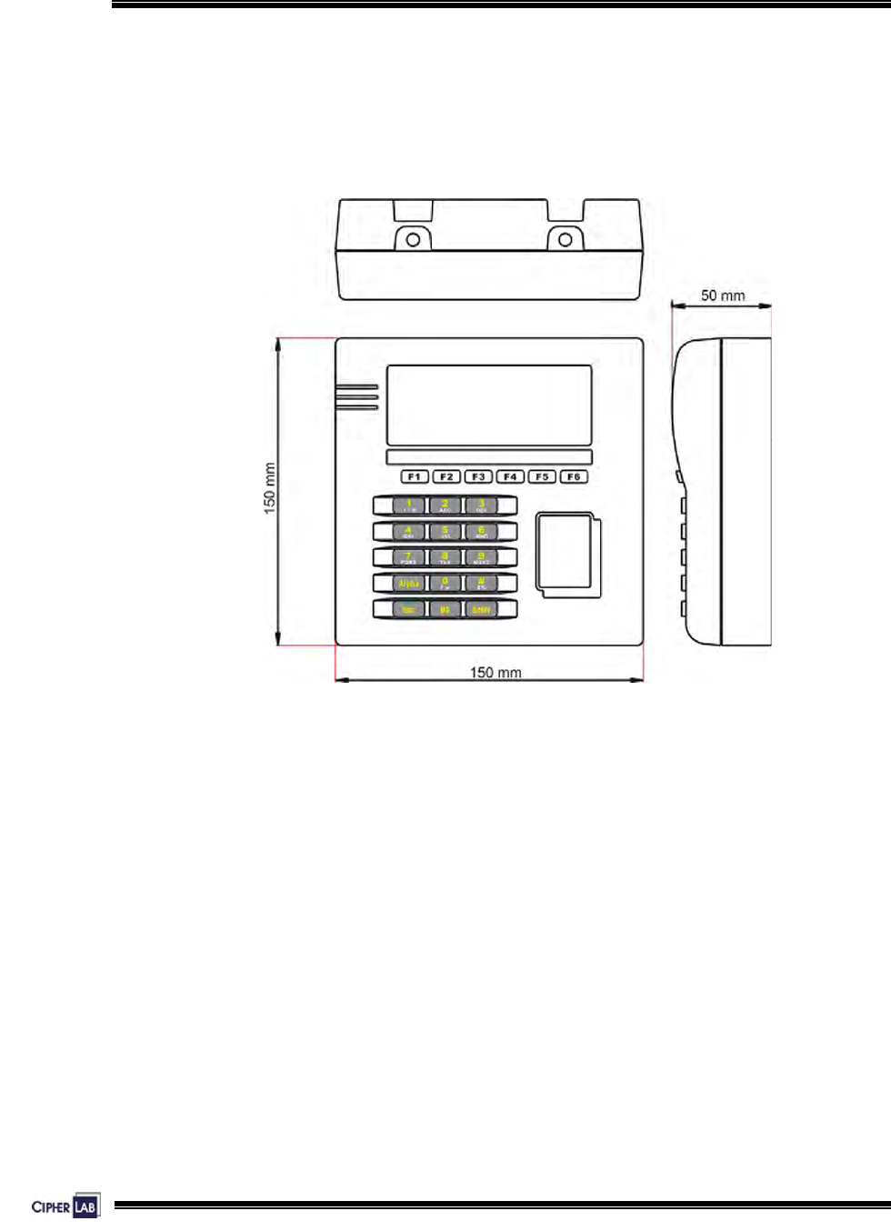
1.2.2 Dimensions
These drawings provide 3-sided views with dimensions, which are helpful in choosing
a suitable location for installation.
Figure 4: Physical dimensions

8
Introducing 5000/5100:
Features
1.3 Features
1.3.1 Power
Line Power & Main Battery
A 12 V/ 1000 mA wall adaptor is used to power the 5000/5100 terminals. Furthermore,
an optional 7.4 V/ 2000 mAh Li-ion battery pack provides more than six extra hours of
uninterrupted operations when the line power is down. Such power switching
mechanism is actuated by a power switch, which seamlessly switches between the
line power and the battery pack without any user’s intervention.
When the line power is resumed and the battery pack has been used up, an on-board
battery charging controller fully charges the battery pack within twenty hours. This
controller chip helps to assure fast and safe charge by monitoring/controlling the
battery voltage, temperature, charging current and so on. It also includes a
mechanism to provide protection from over charging.
When a power outage occurs, the main battery is to maintain operation for more than six
hours.
Backup Battery
In addition, one 3.0 V/7 mAh rechargeable Lithium button cell on the main board
retains data in SRAM and maintains the running of the real-time clock and calendar. It
takes at least twenty-four hours to fully charge the backup battery.
For a fully charged backup battery, it can last for at least one week.
9
Introducing 5000/5100:
Features
Power Consumption Status
The System Menu provides information on power consumption.
z Monitor voltage level: Line / Main / Backup >> Also see Section 4.3.5 Power
For the 5100 terminal, the smart battery icon will replace the plug icon on the screen
when it is battery-operated. Here is another way to tell a low or discharged main
battery from the screen.
z Examine the levels of the smart battery icon
Utilizing the low voltage/power technology, the terminal draws very little power. The
power consumption is estimated in different conditions as follows:
EM reader – backlight off:
backlight on:
backlight on, charging:
55
125
240
mA @ +12V
mA @ +12V
mA @ +12V
Mifare reader – backlight off:
backlight on:
backlight on, charging:
75
155
275
mA @ +12V
mA @ +12V
mA @ +12V
Table 1: Power consumption
It can be easily seen that there are still some rooms for the adaptor’s supply capability.
However, it is strongly recommended to use other supplies to power heavy loads such
as door locks, alarms and so on. Also, if possible, keep these heavy loads electrically
isolated from the terminal. Electronic equipments such as the terminal tend to be
upset by surges from surrounding “noisy” devices.
10
Introducing 5000/5100:
Features
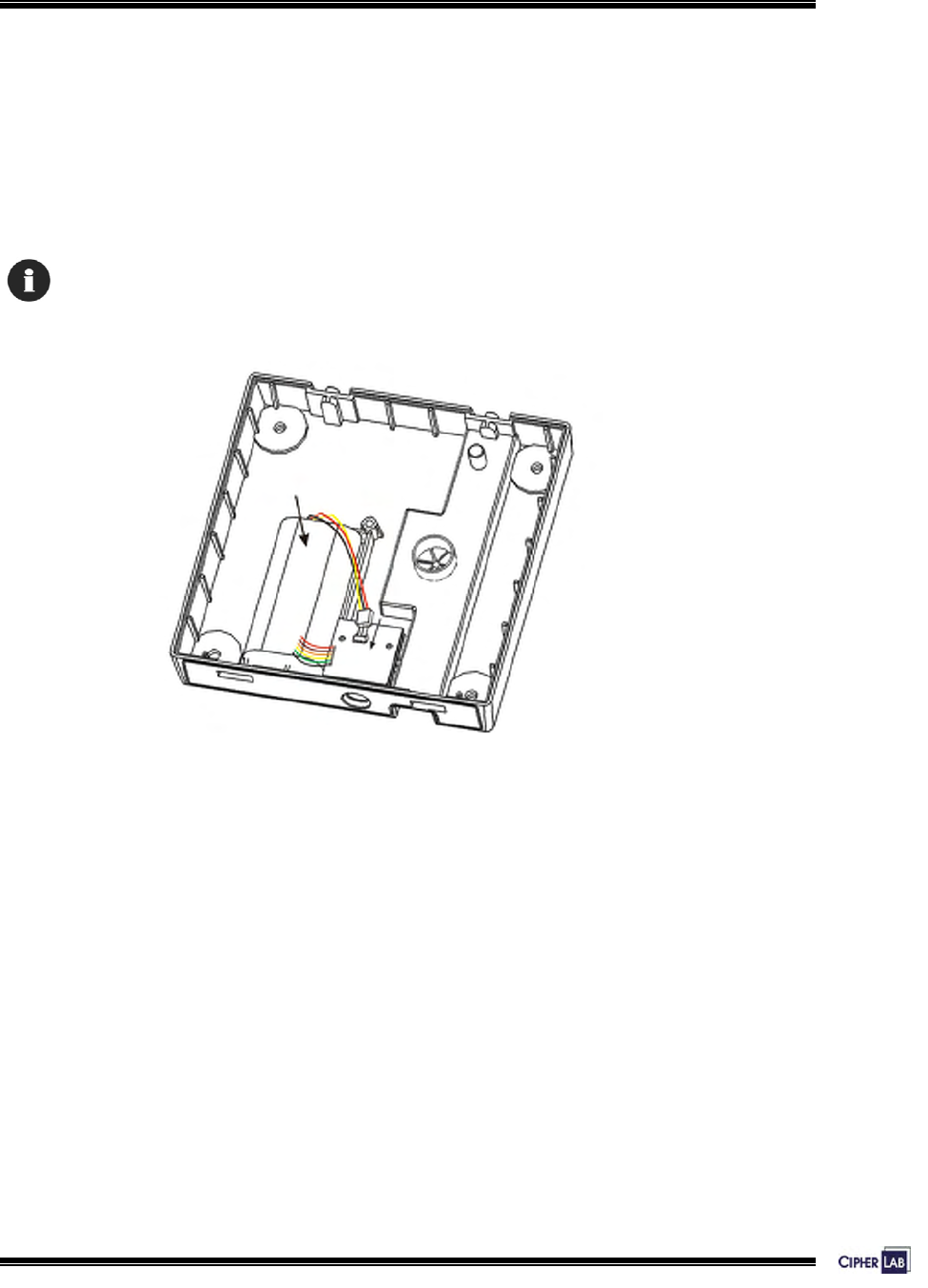
Installing Battery Pack
If there is any need to replace the battery pack, follow the instructions described
below.
1. Seat the battery pack into the battery compartment at the lower enclosure.
2. Connect the battery wires to the receptacle on the charger.
To access the configuration menus, disconnect the battery wires and external line power.
Figure 5: Installing battery pack

11
Introducing 5000/5100:
Features
1.3.2 CPU
A 16-bit low power CMOS CPU is utilized. With little current consumed, yet, this CPU
can run under 22.1184MHz and provide more than 6 MIPS of computation powers.
1.3.3 Memory & Calendar
In the event of a power failure with no battery pack installed, the 7 mAh button cell on
the main board is to keep contents of the SRAM and run the calendar for at least 1
week.
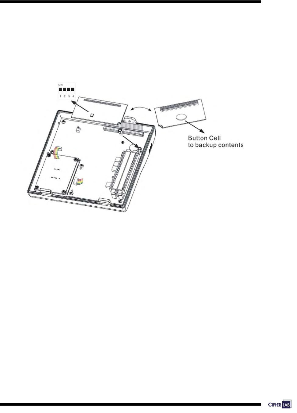
An optional memory card upgrades memory to 2, 4, or 8 Mbytes SRAM with its own
contents backup button cell. The DIP switch on the card must be set ON for the cell to
work.
Program memory:
- 2 Mbytes flash memory for core, OS, application software, fonts, etc.
Data memory:
- 256 Kbytes SRAM with contents backup by a 7 mAh rechargeable Li button cell.
Calendar:
- A calendar chip is also equipped for accurate time/date logging.
- Non-stop operation is also provided through the same Li button cell for SRAM
contents backup.
Table 2: Memory explained
12
Introducing 5000/5100:
Features
Installing Memory Card
1. Align pinholes at the back of the card to the pins on the main PCB.
2. Press down the card flatly. Be careful not to bend or distort any pins.
3. Then apply the screw to screw down to the pole.
Figure 6: Installing memory card
13
Introducing 5000/5100:
Features
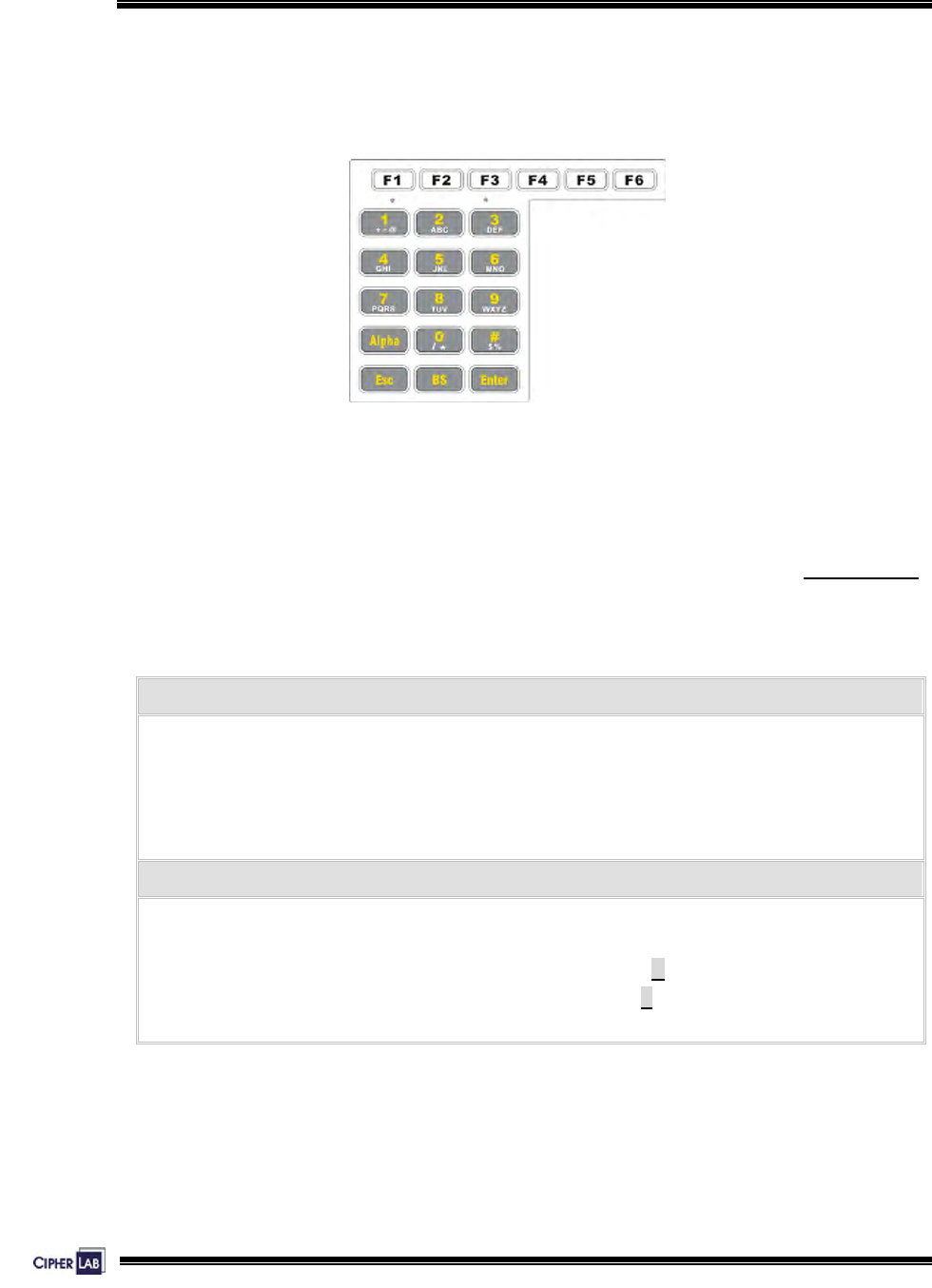
1.3.4 Keyboard
A 21-key keypad is for system setup, user entry and so on.
Figure 7: Keypad layout
Silicon rubber has been chosen for their durability and prompt feedback. The key click
can be configured through the System Menu.
>> Also see Section 4.3.2 Settings
These keys can be categorized into two groups:
Function keys (F1~F6):
- User-definable, each comes with a GREEN LED underneath.
- Can be used to show the current system status such as working shifts, etc.
- Also, in combination with the graphic LCD, user-friendly graphic selection menu
can be implemented.
Alphanumeric keys:
- The alphanumeric keypad layout is similar to phone keypad, and also with GREEN
LED backlight. Default input mode is numeric.
- Capital letters mode: press the Alpha key once and A appears on the screen.
- Small letters mode: press the Alpha key twice and a appears on the screen.
Table 3: Keypad explained
14
Introducing 5000/5100:
Features
Optional External Keyboard
The 5000/5100 terminals provide one keyboard port. You may connect an external
keyboard to this port.
1. Connect wires from the keyboard module to the receptacle on the main PCB.
2. Connect the external keyboard to the PS/2 port.
1.3.5 LCD
The 5100 terminal comes with a 128 by 64 pixels FSTN graphic LCD, which is able to
display message in formats as follows:
English fonts: (6×8 pixels) 21 by 8 lines
(8×16 pixels) 16 by 4 lines
Chinese fonts: (16×16 pixels) 8 by 4 lines
Other language fonts, company logo, etc. Programmable
Table 4: Display formats
The LED backlight helps ease reading under dim environments, and can be
configured through the System Menu. >> Also see Section 4.3.2 Settings
Also, other language fonts, company logo and so on can be shown to accommodate
varying application needs.

15
Introducing 5000/5100:
Features
1.3.6 Status LEDs
There are four indicators on the front panel for status feedback. They are
programmable for diagnostics and application dependant.
z Red LED – Power
z Green LED – Good Read
z Yellow LED – 485 Comm.
z Orange LED – Host Comm.
1.3.7 Buzzer
The buzzer is a low power transducer type, and its pitch and duration are software
programmable.
1.3.8 Readers
Two types of readers are supported:
125 KHz EM: From contact to 6 cm
13.56 MHz, Philips Mifare: From contact to 6 cm
Table 5: Types of readers
A second reader can be attached via the JP2 “external reader port”. Please note that
these are “CMOS level” (0~+5V) signals. A +5V output is also available on the JP2
and can be used to power this external reader.
16
Introducing 5000/5100:
Features
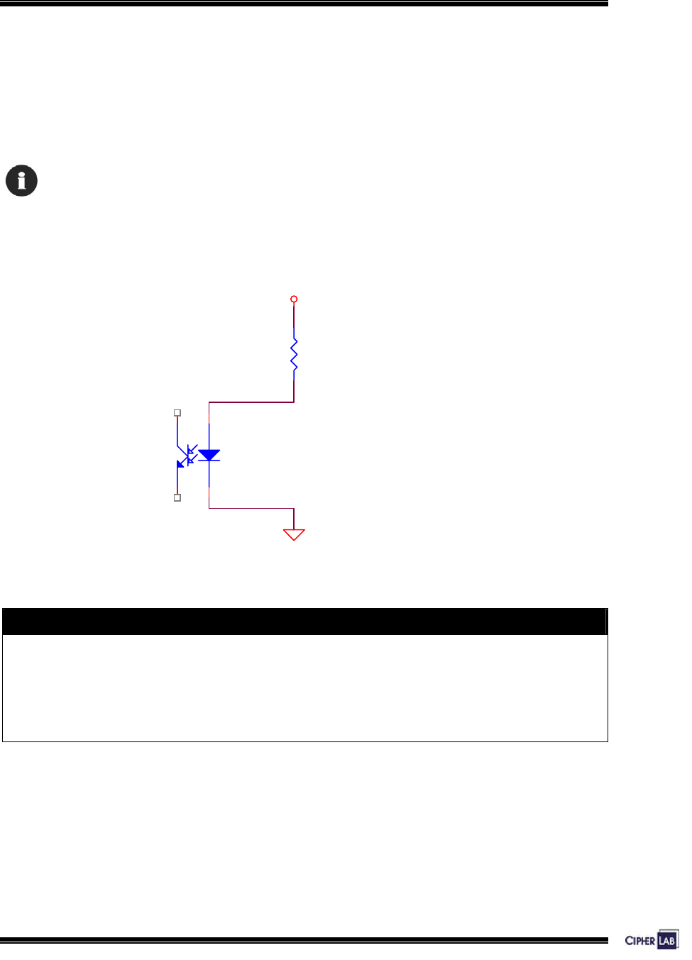
1.3.9 Digital Inputs
There are totally 4 groups of digital inputs. Each is electrically isolated from the
outside world by a photo-coupler. Current must flow through the internal LED to turn
on the output transistor.
A typical 1 mA turn-on current is recommended.
A sample circuit is depicted below.
1
43
2
R
DIN+
DIN-
Vext
external ground
external power
Figure 8: D/I sample circuit
How to decide the R value?
Premise: the LED forward voltage is about 1.15 V.
The recommended R is
Kohms when Vext = 5.0 V, and 10 Kohms when Vext = +12 V.
Table 6: Decide resistance value

17
Introducing 5000/5100:
Features
1.3.10 Digital Outputs
There are totally 4 groups of digital outputs. Each is a relay that is able to sustain 1 A
under 30 VDC or 0.3 A under 125 VAC. Both normal open (NO) and normal close (NC)
contacts are provided to accommodate application needs.
These relays are sufficient to provide direct control over normal house door electric
lock, alarm and so on. External high power relays might be needed for turnstile,
automatic doors and so on to satisfy “heavy loads”.
So, before connecting any devices to the terminals, please check their power ratings
thoroughly.
18
Introducing 5000/5100:
Features
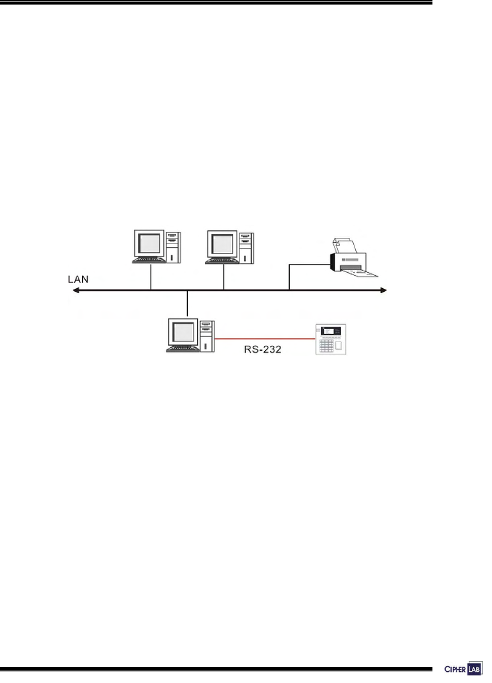
1.3.11 RS-232
A standard RS-232 port is available on the JP3. Unlike the “external reader port”,
these signals are true RS-232C compliant. With proper cabling, shielding, wiring and
so on, it is able to communicate to another device up to 50 feet (approx. 15 meters)
away.
This port is mainly used to communicate to the host computer, i.e. being a
stand-alone unit or master terminal under multi-station systems. The final use, of
course, is not limited.
The illustration below shows a typical topology of networking a standalone terminal to
a host through RS-232 interface.
Figure 9: An example of RS-232 connection
19
Introducing 5000/5100:
Features
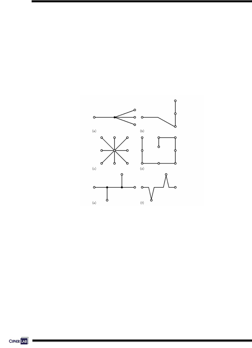
1.3.12 RS-485
A standard RS-485 port is also available on the JP3 to constitute multi-station
systems. Though it is simple and low cost, care must be taken to ensure proper
operations.
z The data rate is 125 kbps.
z Compatible to CipherLAB 510, 520 and so on.
z Maximum network run length is 1000 meters
z No fork, nor star connections. As depicted below, connections b, d & f are
acceptable but not others.
Figure 10: RS-485 topology
z Use AWG 22, shielded twist cables or Cat 5 UPT cables.
z Terminators help to absorb reflections and should be placed at both “physical”
ends. A slide switch turns on/off an on-board termination circuitry.
z For the RS-485 network to work properly, a unique station ID has to be assigned
to each terminal first.
20
Introducing 5000/5100:
Features
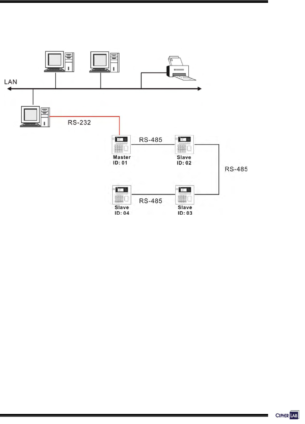
The illustration below shows a typical topology of networking multiple terminals
through RS-232 and RS-485 interfaces.
Figure 11: An example of RS-485 connection
21
Introducing 5000/5100:
Features
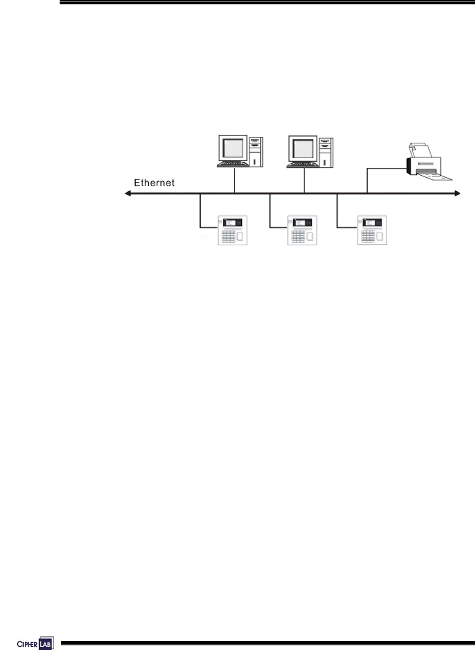
1.3.13 Ethernet
An optional 10/100 Base-T Ethernet card can be attached to merge the terminals onto
any existing legacy Ethernet networks. It comes with a standard RJ-45 connector and
is fully standard compliant. Just like the RS-485, the IP address must be set
accordingly.
Figure 12: An example for Ethernet networking
22
Introducing 5000/5100:
Features
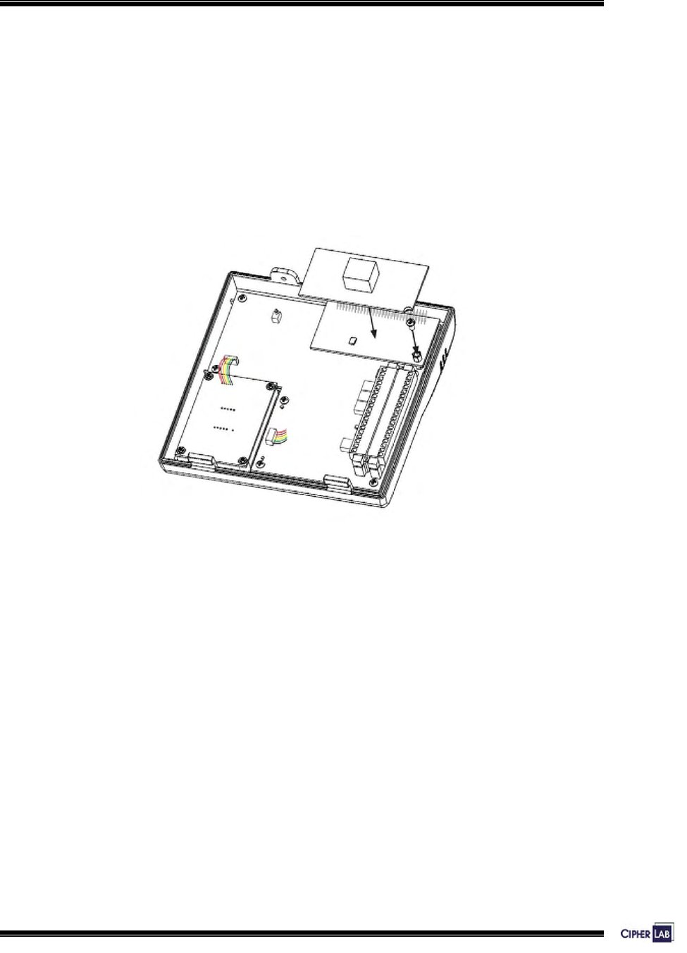
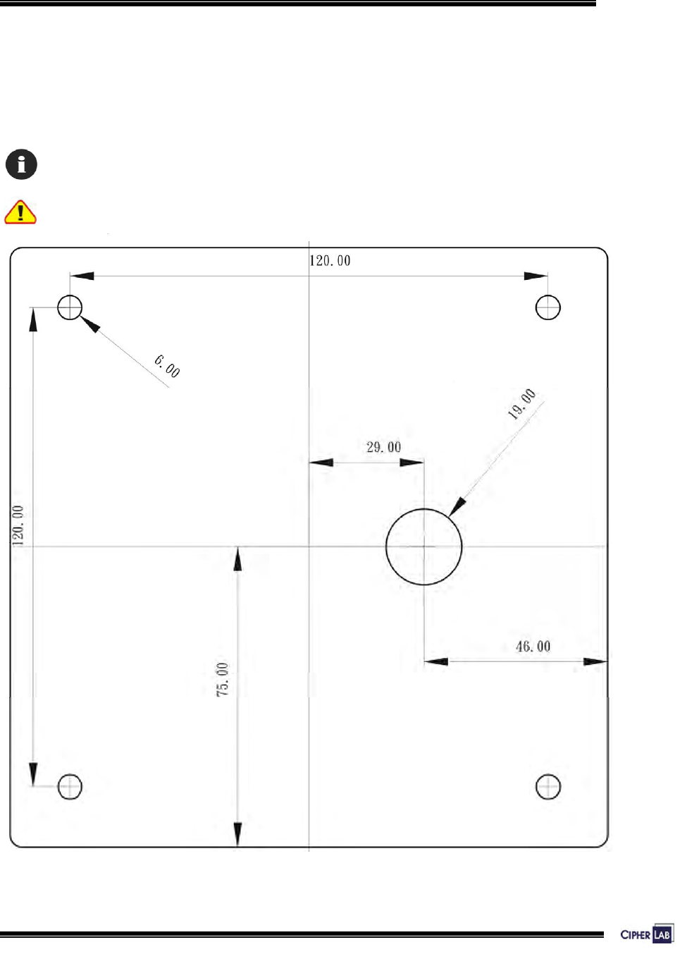
Installing Ethernet Card
You may have to install the Ethernet card to the terminal by yourself. If you have
installed a memory card, attach the Ethernet card on top of it then.
1. Align the pinholes at the back of the card to the pins on the main PCB.
2. Press down the card flatly. Be careful not to bend or distort any pins.
3. Then apply the screw to screw down to the pole.
Figure 13: Installing Ethernet card
1.3.14 Programming Support
For custom applications, development tools include BASIC and C compliers.
In addition, OCX support is also available for proprietary 5100*.SHX application
programs.
23
Introducing 5000/5100:
Unpacking & Options
1.4 Unpacking the package
The following items are included in the package. Save the box and packaging material
for future use when you need to store or ship the terminal.
z The 5000 or 5100 Terminal
z Power Adaptor
z Software CD & Reference Manual (for authorized distributors only)
1.5 Options
There are several optional accessories to enhance the total performance of the
terminals. Some of them may be ordered separately, and therefore, require you to
install them to the main PCB by yourself.
For installation details, please refer to relevant sections.
Memory card: 2, 4 or 8 MB SRAM for data memory
Reader: Built-in RFID reader, Mifare or EM type
Battery pack: Rechargeable Li battery for non-stop operation
Ethernet card: RJ-45 port for 10/100Base-T Ethernet networking
Table 7: Optional accessories
24
2. INSTALLING 5000/5100
2.1 Setting up the terminal
The whole installation can be simply classified into the following stages:
Site Survey:
Choose a location that is close to the target door and provides clearance for the cables
and access to an AC outlet.
Mounting:
- Drill holes on the wall.
- Mount the lower enclosure on the wall.
Attaching:
Attach optional accessories to the PCB.
Wiring & Connecting:
- Connect wires to terminal blocks.
- Connect connectors to receptacles.
- Connect to Ethernet networks.
Assembling:
Secure enclosures.
Power Supplying:
Connect to an appropriate wall outlet.
Table 8: Stages of installation
The site survey should take both location and topology into consideration. And the
actions specified for each stage should be taken with care to avoid any damages to
the terminals or peripherals.
To ensure proper wiring and safe operation, we strongly recommend that the terminals be
set up by an experienced electrician.
25
Installing 5000/5100:
Setting up the terminal
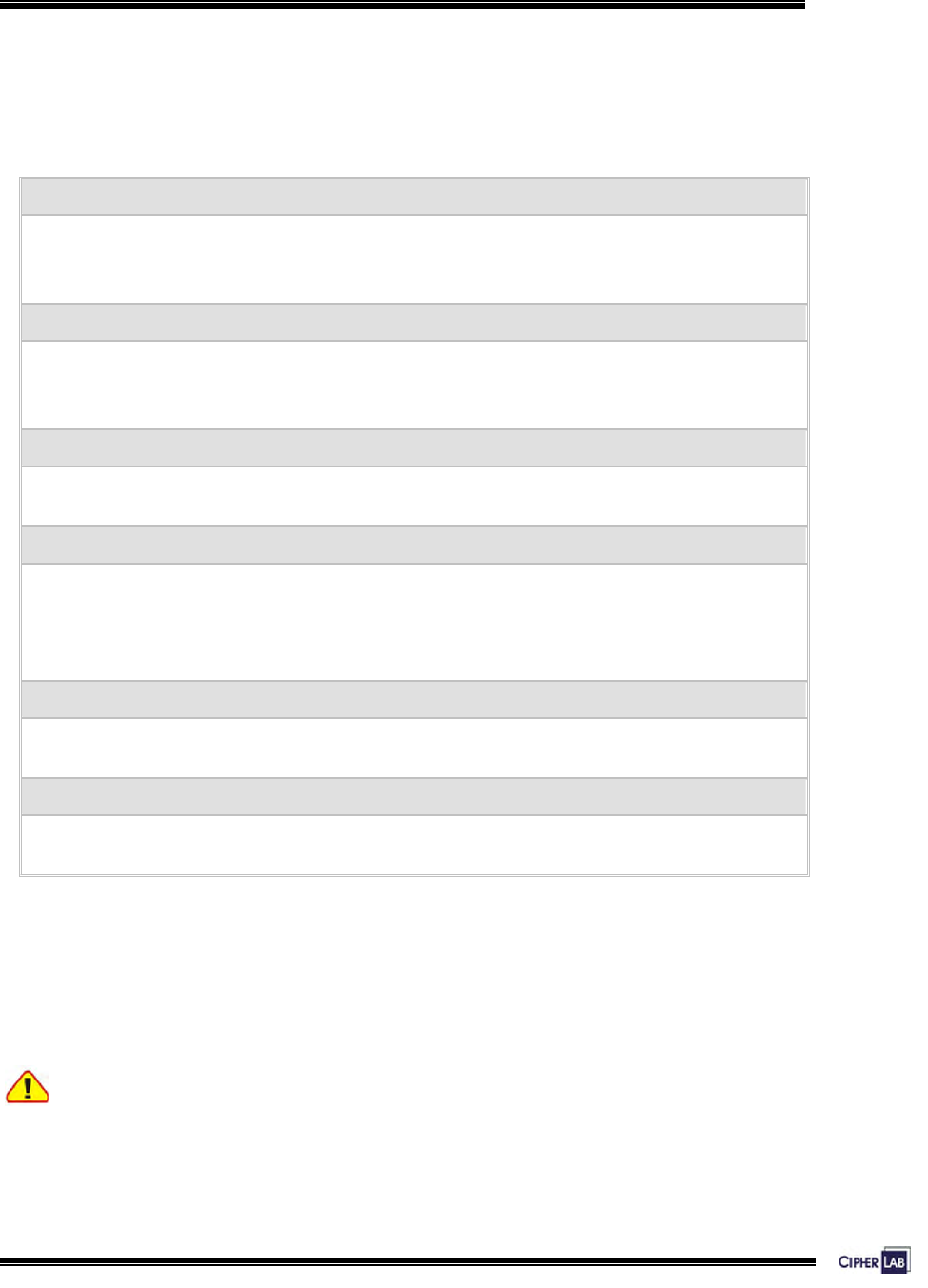
Figure 14: Drilling holes & assembling cables
Drilling Holes & Assembling Cables
1. Make use of the mounting template provided in the appendix, and drill four holes
in an appropriate location for installing the terminal:
z Each hole shall be 6 mm in diameter and 21 mm in depth.
z The four holes enclose a square of 120 mm x 120 mm.
2. Insert the four wall plugs (screw anchors for concrete surface) into the four holes.
Make sure each of them is completely inside a hole.
3. Pull cables through the cable entry hole . Apply the two-piece cable holder
to organize the in-coming cables, and secure the holder to the pole by screw.
26
Installing 5000/5100:
Setting up the terminal
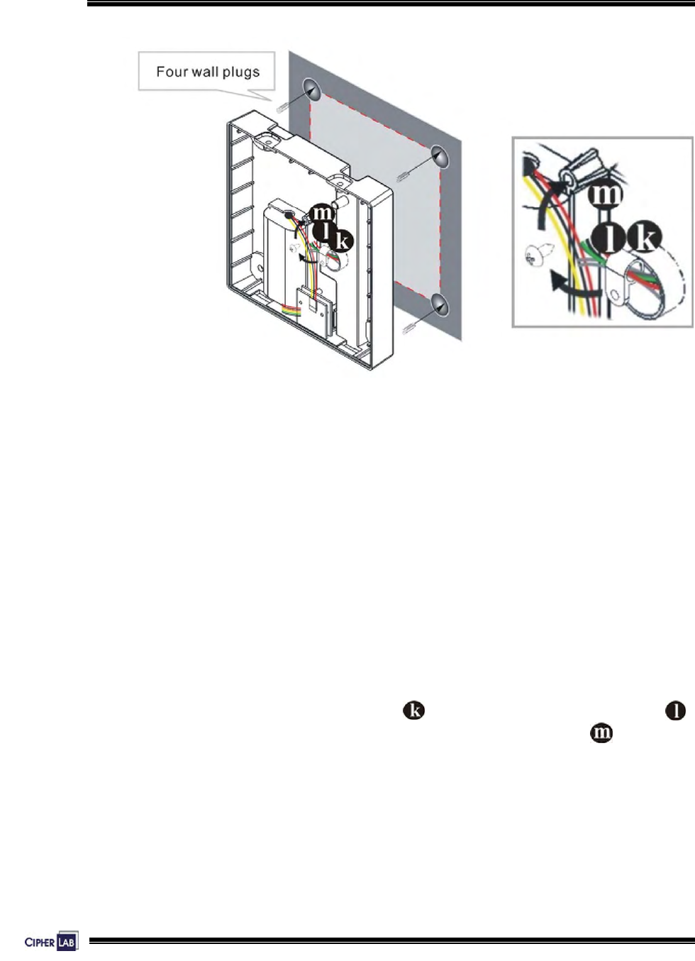
Figure 15: Mounting to wall
Mounting to the Wall
4. Make sure the cables are routing and arranged in the cable channel at the back.
Such design is to keep cables invisible and inaccessible from the outside.
5. Apply four 4x16 screws to mount the lower enclosure on the wall.
Attaching Optional Items
6. Attach the battery pack, memory card and Ethernet card, if there is any.
>> Also see Sections 1.3 Features & 1.5 Options
27
Installing 5000/5100:
Setting up the terminal
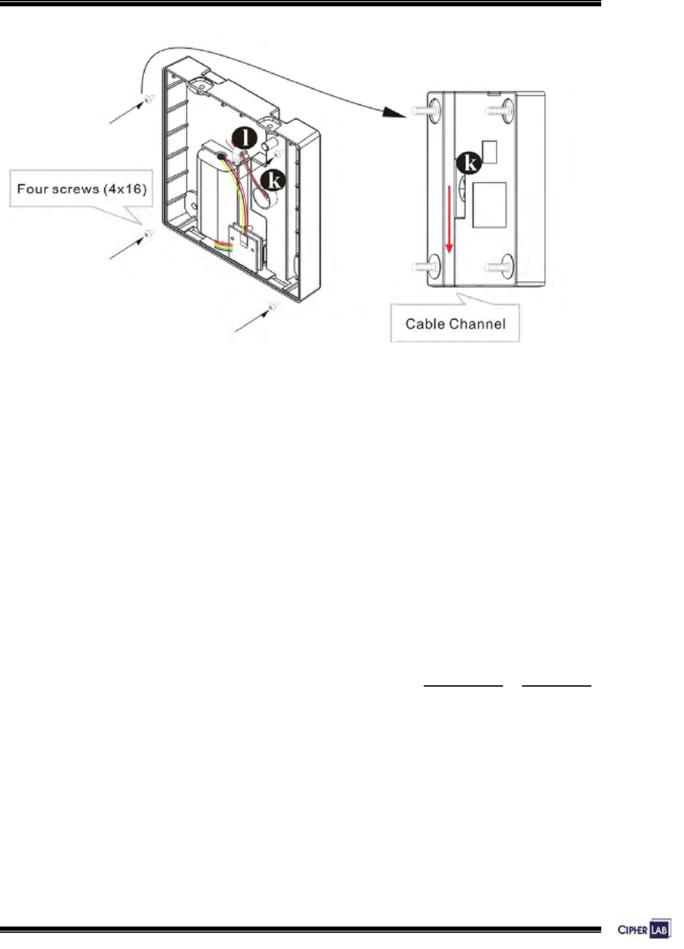
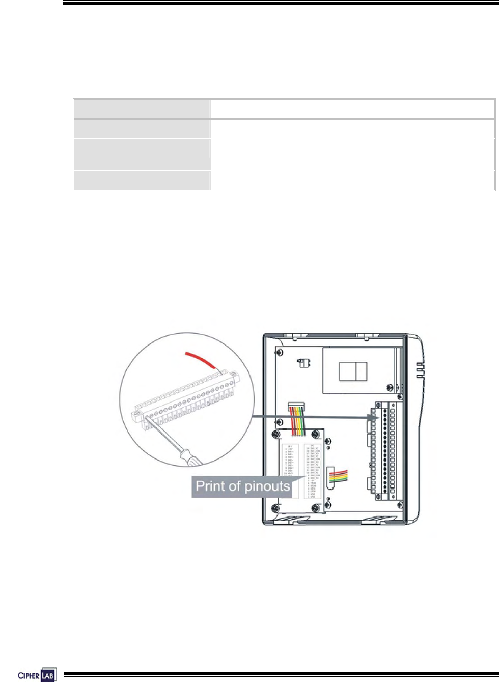
Figure 16: Wiring & connecting
Wiring & Connecting
7. Attach connectors of the keyboard module, reader module, charger or battery
pack to receptacles on the PCB.
8. Follow the wiring instructions to insert every wire to a corresponding slot of the
terminal blocks . Tighten screws to secure wires. Then plug the terminal block
in to the PC board socket.
z Connect line power.
z Connect digital inputs and outputs.
z Connect RS-232, if necessary
z Connect RS-485, if necessary
9. If the Ethernet card is installed, simply connect a standard networking cable
(two ends with RJ-45 connectors) to the Ethernet ports on the module and your
networking device.
Proceed to enable TCP/IP and set other networking parameters.
28
Installing 5000/5100:
Setting up the terminal
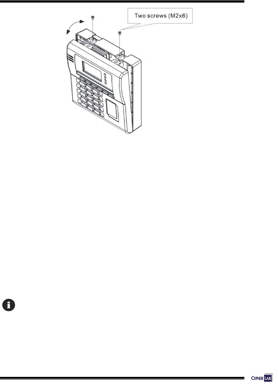
Figure 17: Assembling enclosures
Assembling Enclosures from Bottom to Top
10. Make sure there is no more need to do hardware configuration and/or
downloading application program.
At last, position the two tabs at the bottom of the upper enclosure into the notches
at the bottom of the lower enclosure. The two pieces of enclosures snap to fit.
11. Apply two M2x6 screws to secure the upper enclosure to the lower enclosure on
top.
Connecting to Power
12. Connect the power adaptor to an outlet.
When being installed for the first time, both the battery pack and the button cell for memory
backup take a certain time to be fully charged.
29
Installing 5000/5100:
Wiring
2.2 Wiring
This section gives instructions on how to wire the terminal to external devices, a host,
or another terminal.
RS-232 (JP3) Connect to a host computer
RS-485 (JP3) Connect to another terminal
Digital inputs (JP3) Connect to external devices like an actuator (button) to
open door
Digital outputs (JP2) Connect to external devices like door lock, siren, etc.
Table 9: Types of interfaces
To ease installation and maintenance, most of the wirings (except for the Ethernet)
are through JP2 and JP3. These connectors are detachable terminal blocks. That
means, soldering is not required and these terminal blocks can be separated from the
main PCB easily.
Figure 18: Terminal blocks

30
Installing 5000/5100:
Wiring
2.2.1 Pin Assignments
The pin assignments are listed and described below.
JP2:
Pin No. Name Category Description
1 GND Power Ground
2 GND Power Ground
3 CTS0 From External reader CMOS-level clear to send
4 RTS0 To External reader CMOS-level request to send
5 RXD0 From External reader CMOS-level receive data
6 TXD0 To External reader CMOS-level transmit data
7 +5V Power +5V/200mA to power external
devices
8 DO4_NO Digital output #4, normal open
9 DO4_COM Digital output #4, common
10 DO4_NC Digital output #4, normal close
11 DO3_NO Digital output #3, normal open
12 DO3_COM Digital output #3, common
13 DO3_NC Digital output #3, normal close
14 DO2_NO Digital output #2, normal open
15 DO2_COM Digital output #2, common
16 DO2_NC Digital output #2, normal close
17 DO1_NO Digital output #1, normal open
18 DO1_COM Digital output #1, common
19 DO1_NC Digital output #1, normal close
Table 10: Pin Assignment of JP2

31
Installing 5000/5100:
Wiring
JP3:
Pin No. Name Category Description
1 +5V Power Same as JP2 pin 7, i.e. total
current can be drawn from
these two pins is 200 mA
2 DIN1+ Digital input #1 positive side (anode)
3 DIN1- Digital input #1 negative side (cathode)
4 DIN2+ Digital input #2 positive side
5 DIN2- Digital input #2 negative side
6 DIN3+ Digital input #3 positive side
7 DIN3- Digital input #3 negative side
8 DIN4+ Digital input #4 positive side
9 DIN4- Digital input #4 negative side
10 485+ RS-485 Non-inverting
11 485- RS-485 Inverting
12 GND Power Ground
13 TXD1 RS-232 to external device Transmit data
14 RXD1 RS-232 from external device Receive data
15 RTS1 RS-232 to external device Request to send
16 CTS1 RS-232 from external device Clear to send
17 GND Power Ground
18 Vsys System power +12V (from adaptor) or main
battery
19 Vsys System power +12V (from adaptor) or main
battery
Table 11: Pin Assignment of JP3
32
Installing 5000/5100:
Wiring
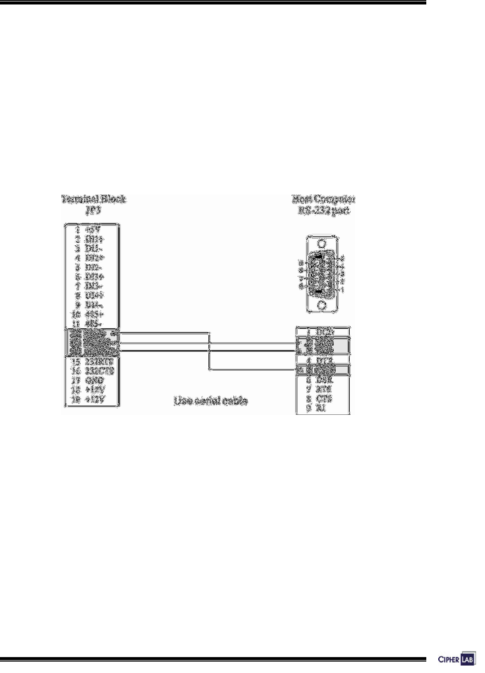
2.2.2 RS-232
Without using additional devices like optical isolators or signal boosters, the cable
length is limited to 50 feet (approx. 15 meters) to ensure communication quality
according to IEEE standard.
Instructions
Make use of a 9-pin female connector (DB-9) at PC end, and wire pins as follows:
Figure 19: RS-232 wiring
Wiring materials:
Use 22 ~ 24 AWG braided shielded cable.
33
Installing 5000/5100:
Wiring
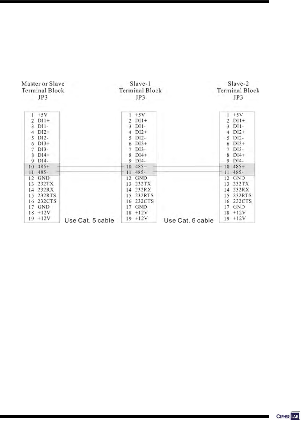
2.2.3 RS-485
Connections between every two terminals are set up through RS-485 interface. When
more than two of the terminals are connected (as a multi-station system), a host only
needs to connect to the first one terminal (master) and it can then communicate with
the rest terminals (slave).
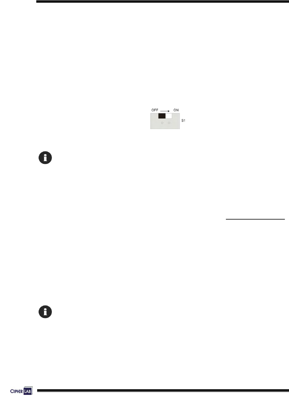
On the last slave device, a termination resistor is usually essential. There is one
terminator on the PCB of each terminal, and a DIP switch (s1) is beside JP3. When
the terminal serves as the last one slave device, please turn on the switch.
Figure 20: Terminator’s switch
Slide the DIP switch to the right position on the last salve device.
To establish such RS-485 connection, the following settings need to be done first on
the hardware of the terminals. For preloaded applications, set parameters from the
front panel by entering the Setup Menu.
>> Also see Section 3. System Architecture
z Line Connection:
Only the device connected to a host is named “Master”, the rest are all “Slave”.
z Station ID:
Assign a unique ID (01 ~ 99) to each terminal.
z Maximum station ID:
Set a value (01 ~ 99) as the maximum station ID of the polling list on the Master.
For RS-485 connection without any repeaters, up to 32 stations can be connected.
34
Installing 5000/5100:
Wiring
Instructions
When settings are completed, you may proceed with physical connection between
every two terminals.
To set up RS-485 connection, the communications cable must be wired as shown
below:
Figure 21: RS-485 wiring
Wiring materials:
Please use 22 AWG braided shielded cable or Cat 5 UTP (Unshielded Twisted Pair)
cable. The maximum cable length can be up to 1000 meters.
35
Installing 5000/5100:
Wiring
2.2.4 Digital Inputs/Outputs
DI/DO are four sets of separate signal on the terminals.
DI via JP3
D/I type: A photo-coupler that can be used to monitor external devices.
For example, a button can be used to activate and open a door.
DI wiring allows four groups of signals and is done through JP3.
DI Group No. Pin No. (+) Pin No. (–) Pin No. (+5V) Pin No. (GND)
DIN1 (Default) 2 3 1 17 or 12
DIN2 4 5 1 17 or 12
DIN3 6 7 1 17 or 12
DIN4 8 9 1 17 or 12
Table 12: D/I groups
DO via JP2
D/O type: A relay that can be used to control external devices.
For example, an alarm can be activated for alerting abnormal status.
Or, a door lock switch to lock the door for a certain condition.
DO wiring allows four groups of signals and is done through JP2.
DO Group No. Pin No.
(Normal Open)
Pin No. (Common) Pin No.
(Normal Close)
DO1 (Default) 17 18 19
DO2 14 15 16
DO3 11 12 13
DO4 8 9 10
Table 13: D/O groups
36
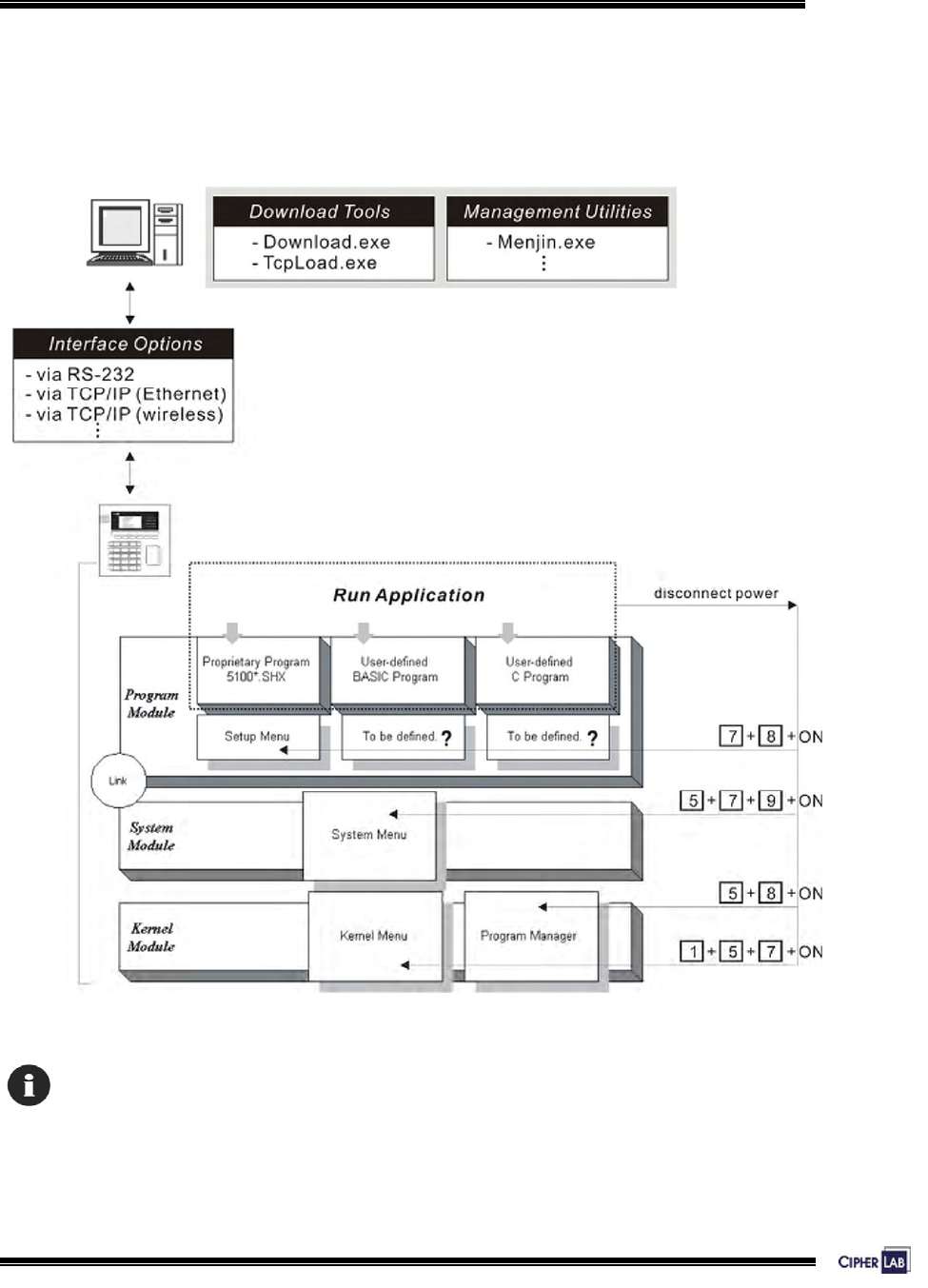
3. SYSTEM ARCHITECTURE
The whole system can be simplified as hardware and software at PC end and terminal
end. The software inside the terminal mainly consists of three modules: Kernel,
System, and Program. For system configurations and managing multiple programs,
each terminal comes with System Menu, Kernel Menu, and Program Manager.
Figure 22: System Architecture
Program Manager Menu, which is generated by 51pm.shx, is unavailable by default.
Please download 51pm.shx in the System Manu first.
37
System Architecture:
Operation
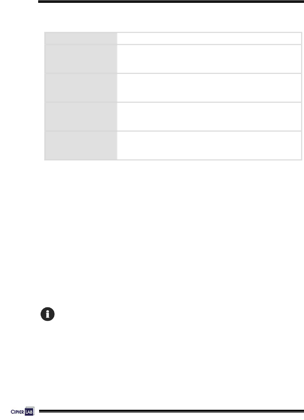
According to different purposes for which the modules serve, the software inside the
terminal also can be viewed in the following way:
Menus Purposes
Setup Menu
OR
User-defined menu
Setup Menu is generated by the proprietary 5100*.SHX
program. The menu functions and access keys depend on
the application program you download to the terminal.
System Menu
A portal to system configurations.
Kernel Menu
Generally, this is for manufacturing use only.
Program Manager
A portal to manage multiple programs.
Table 14: Purposes of software modules/menus
Because the 5000 terminal comes without the LCD screen, we suggest you keep the
manual at hand while configuring the terminals.
3.1 Operation
After being properly configured and physically set up together with peripherals, the
terminal is ready to work when a corresponding management utility is ready at PC
end.
Applications scope include Access Control system, Time & Attendance, Shop Floor
Control, etc. It depends on which application program is running.
Proper configuration is very important for a system that consists of a number of terminals.

38
System Architecture:
Download
3.2 Download
The terminal must be configured correctly for downloading either of the following:
z Program update
z New application program
z Font file (only RS-232 interface is allowed)
Proprietary Application Programs (5100*.SHX):
The following programs have been developed to meet varying application needs.
One of them is preloaded inside the terminal.
- Access Control: 5100AC-MS-V1.0.SHX
- Time & Attendance: 5100T&A-V1.0.SHX
- Shop Floor (Work-in-Process, WIP): 5100SF-V1.0.SHX
Corresponding to each of these programs, a Setup Menu is available on the terminal
for setting parameters.
Alternatives:
Aided by programming support, user-defined application programs can be developed
to satisfy specific needs as being part of a system.
Table 15: Application programs

39
System Architecture:
Management
3.3 Management
Install a management utility at PC end that corresponds to the current application.
Then, proceed to define the environments for the terminal to work.
Please see programming guide for details.
The terminal must be loaded with an appropriate application first.
Proprietary Management Software for 5100*.SHX:
The software is in correspondence to proprietary application programs.
- Several PC end utilities are available for remote management. For example,
Menjin.exe is for access control system.
- Aided by OCX support, customized management utilities can be developed.
- Command sets are mainly for managing the terminals. Yet, sending commands
from a host can do part of the configuration as well.
Alternatives:
The custom management software is specifically in correspondence to user-defined
application programs.
Table 16: Management programs
40
4. CONFIGURING 5000/5100
This section mainly describes the alternatives to configure the 5000/5100 terminals,
including hardware configuration and downloading application programs.
Although the 5000 terminal is not equipped with a screen, you may proceed with
configurations by following the LED indicators and relevant sample screens of menus
in this manual.
Without a screen, some menus are not operational on the 5000 terminal.
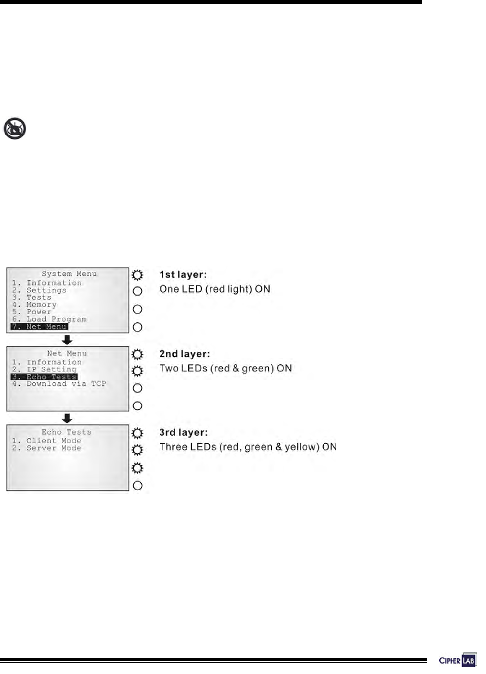
4.1 Identifying current menu
With or without a screen, the LEDs on the front panel will indicate the current layer of
menus when configuring settings.
Screen 1: Status lights as menu indicators
41
Configuring 5000/5100:
Selecting from menus
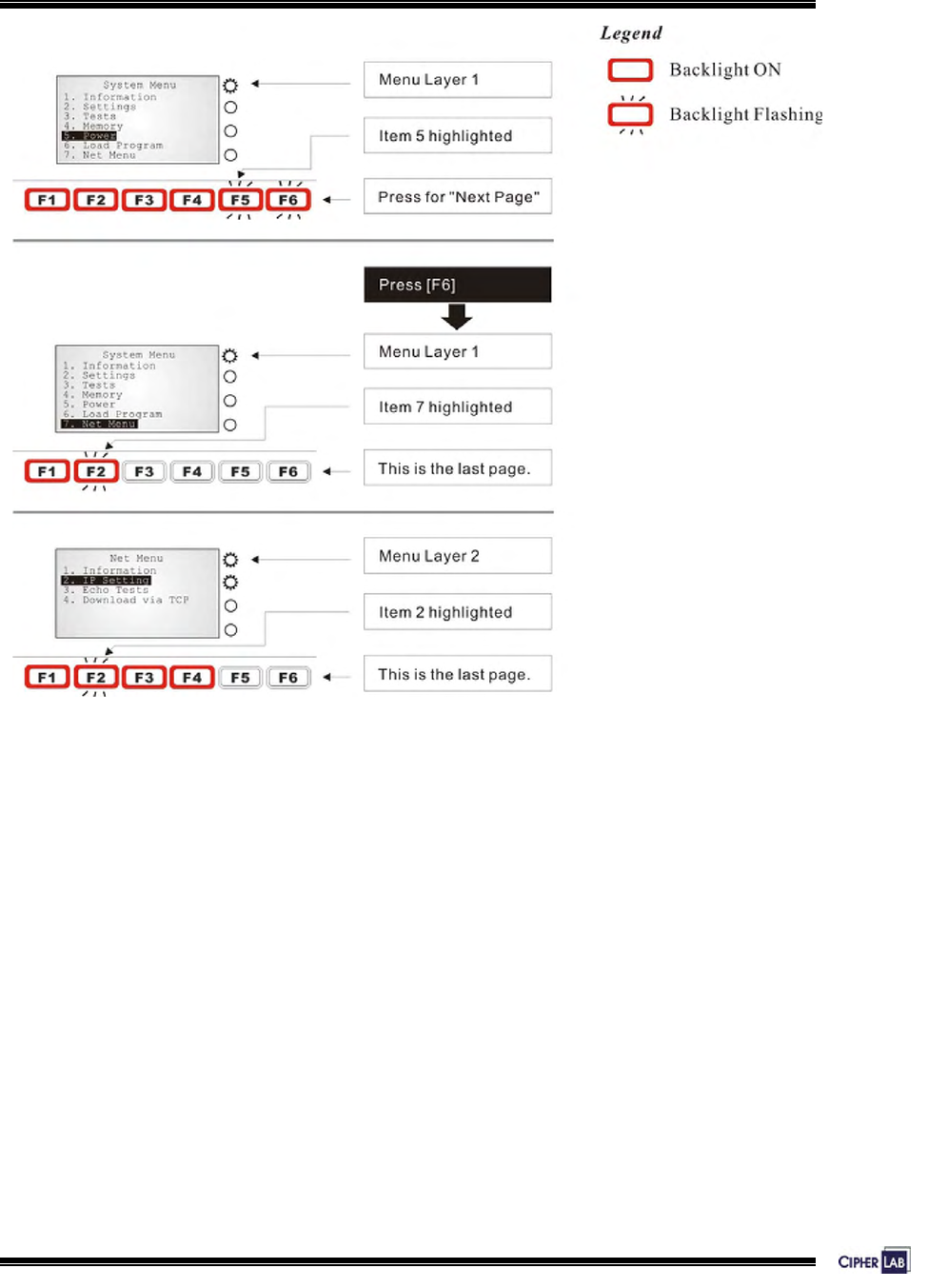
4.2 Selecting from menus
The function keys can also be used in selecting item from menus on the screen.
z To select item 1 to 5 on any menu, simply press [F1] to [F5].
z To select item 6 on any menu, press [F6] then [F1].
z To select item 7 on any menu, press [F6] then [F2].
F1 = 1 + [Enter]
F2 = 2 + [Enter]
F3 = 3 + [Enter]
F4 = 4 + [Enter]
F5 = 5 + [Enter]
F6 = Next page
F6 followed by F1 = 6 + [Enter]
F6 followed by F2 = 7 + [Enter]
Table 17: Function keys used in selecting from menus
42
Configuring 5000/5100:
Selecting from menus
Figure 23: Function keys as menu indicators
43
Configuring 5000/5100:
System Menu
4.3 System Menu
The System Menu is generated by a powerful utility, which offers an interface for
engineers (programmers or system integrator) to view system information, change the
configuration parameters, manage files and run diagnostics.
This menu is designed for engineering tests and maintenance ONLY. For this reason,
the System Menu provides password protection to prevent unauthorized users from
accidentally changing system settings.
Warning! The System Menu is NOT for the use of any end users.
The system password helps ensure system safety and integrity.
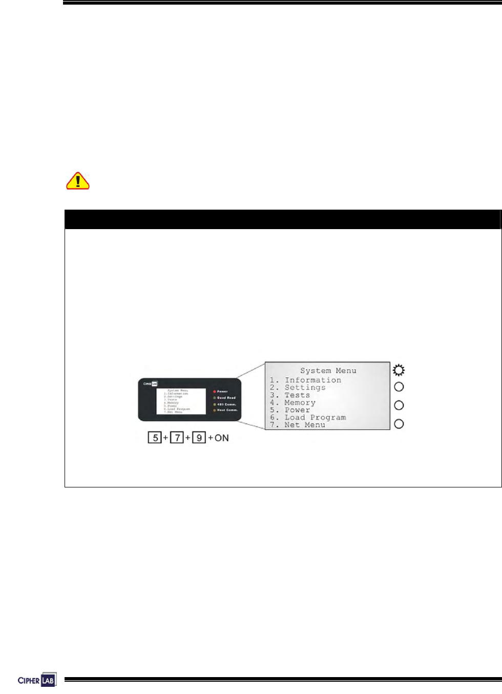
How to access the System Menu?
1. Lift the upper enclosure by unscrewing the two screws on top of the terminal.
2. Disconnect BOTH the line power and main battery.
3. Re-connect the main battery and simultaneously press [5] + [7] + [9] from the
keyboard.
4. The System Menu is displayed on the LCD screen as shown below.
5. Re-connect the line power when configuration is done.
* Net Menu is available only when Ethernet card is present.
Figure 24: System Menu
44
Configuring 5000/5100:
System Menu
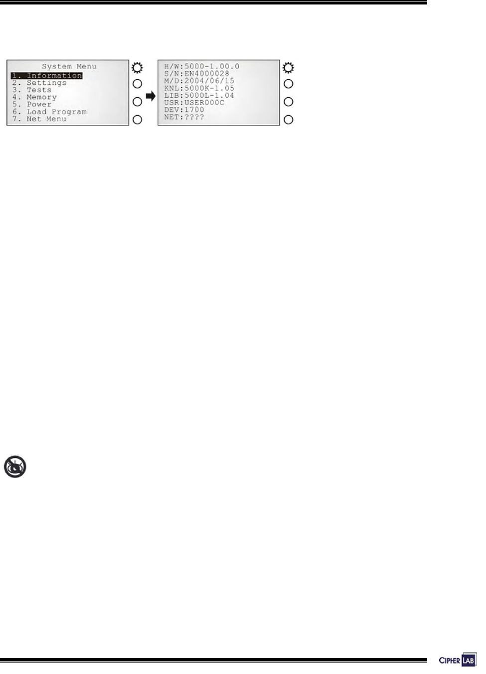
4.3.1 Information
Screen 2: System Menu> 1. Information
The information provided here helps diagnose the system.
z H/W: Hardware version (PCB)
z S/N: Serial number of the terminal
z M/D: Manufacturing date
z KNL: Kernel version
z LIB: C library version
z USR: Application program version
z DEV: Code for optional hardware configurations, i.e. 1700.
See Kernel> Information for device code.
z NET: Serial number of Ethernet card if installed
Without a screen, this is not available on the 5000 terminals.
45
Configuring 5000/5100:
System Menu
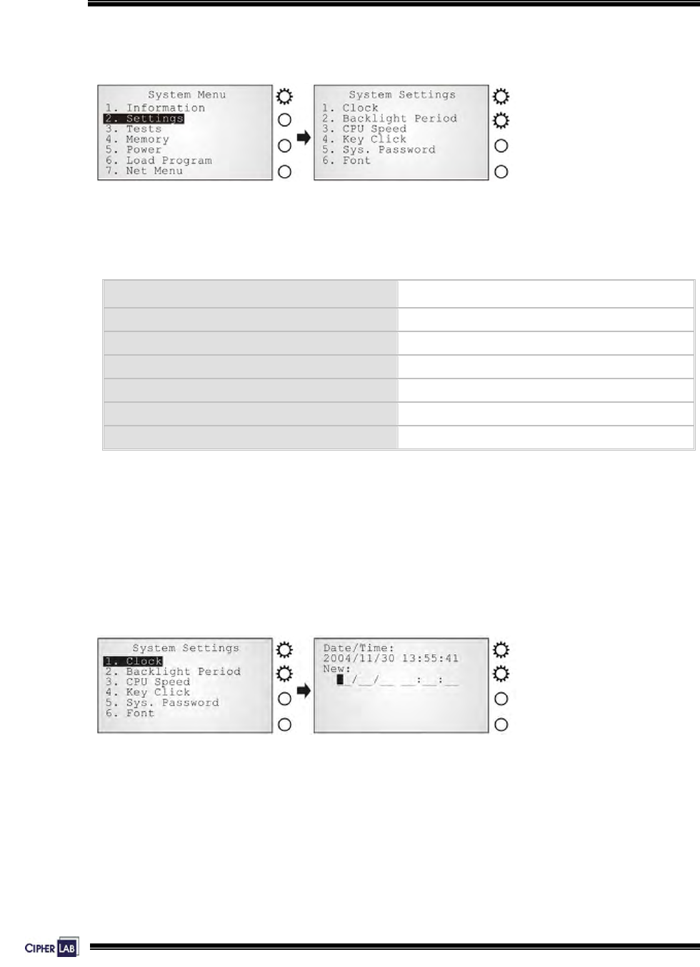
4.3.2 Settings
Screen 3: System Menu> 2. Settings
Here provides options to change the default settings.
System settings Default values
Clock N/A
Backlight Period 20 seconds
CPU Speed Full speed
Key Click Tone 2
System Password Open access
Font System font
Table 18: Default system settings
Settings > Clock
Set date and time for Real Time Clock.
Enter two digits for the year, i.e. 04 for 2004.
Screen 4: System Menu> 2. Settings> 1. Clock
46
Configuring 5000/5100:
System Menu
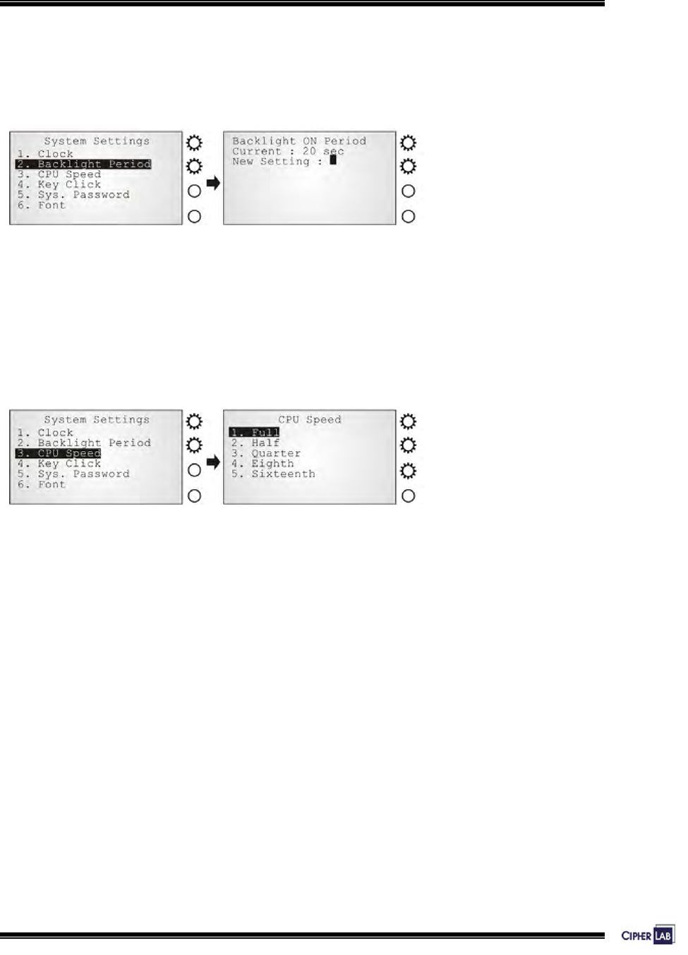
Settings > Backlight Period
Set the backlight duration for the keypad and LCD.
Enter a value between 0 and 99999.
Screen 5: System Menu> 2. Settings> 2. Backlight Period
Settings > CPU Speed
Set the CPU speed to save power if necessary. The current value is highlighted.
Options include: Full, Half, Quarter, Eighth and Sixteenth.
Screen 6: System Menu> 2. Settings> 3. CPU Speed
47
Configuring 5000/5100:
System Menu
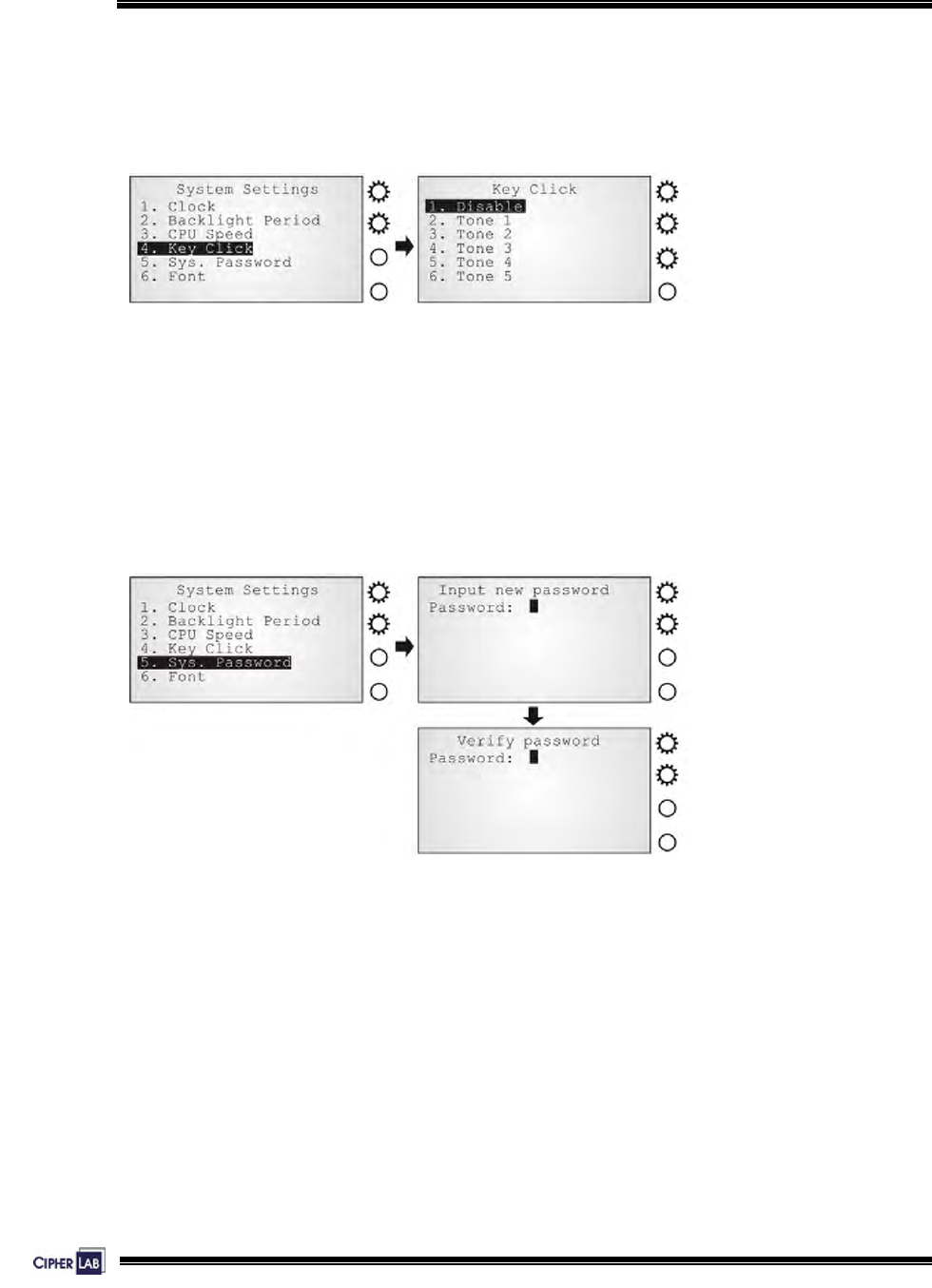
Settings > Key Click
There is audible feedback for pressing a key on the keypad.
The current value is highlighted. Select a tone for the buzzer or mute it.
Screen 7: System Menu> 2. Settings> 4. Key Click
Settings > System Password
Set a password to control user access to the System Menu.
The password consists of eight characters at most.
To disable a previous password, enter blank on the following screens.
Screen 8: System Menu> 2. Settings> 5. System Password
48
Configuring 5000/5100:
System Menu
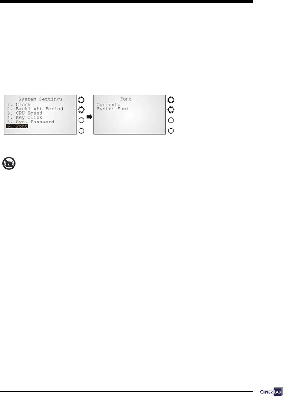
Settings > Font
Current font information can be viewed here.
z Default: System font
z Custom font file, if there is one
The font settings here can be changed if a multi-languages font file has been
downloaded. (Press [2] / [8] to move down / up the menu of options.)
Screen 9: System Menu> 2. Settings> 6. Font
Without a screen, this is not available on the 5000 terminals.
49
Configuring 5000/5100:
System Menu
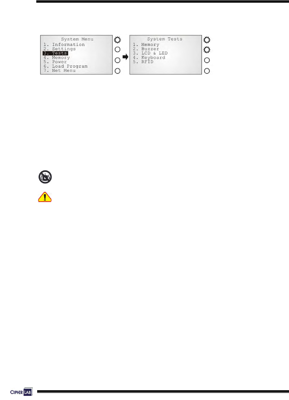
4.3.3 Tests
Screen 10: System Menu> 3. Tests
Here provides functional tests for key parts:
Tests > Memory
Test the data memory (SRAM), and the results will be shown on the screen.
Press any key to exit.
Without a screen, this is not available on the 5000 terminals.
Warning! The contents of the data memory (SRAM) will be wiped out after test.
Tests > Buzzer
Test the buzzer with different frequency/duration combinations.
Press [Enter] to start. Press any key to stop and exit the test.
50
Configuring 5000/5100:
System Menu
Tests > LCD & LED
Test the LCD display and LED indicator.
Press [Enter] to start. Press any key to stop and exit the test.
You may only be able to test the LED indicators on the 5000 terminals.
Tests > Keyboard
Test the rubber keys.
Press any key and its corresponding character will be shown on the screen.
Press [ESC] to stop and exit the test.
Without a screen, this is not available on the 5000 terminals.
Tests > RFID
Test the reading performance of the RFID reader when a proximity card is present.
Press [ESC] to stop and exit the test.
Without a screen, this is not available on the 5000 terminals.
51
Configuring 5000/5100:
System Menu
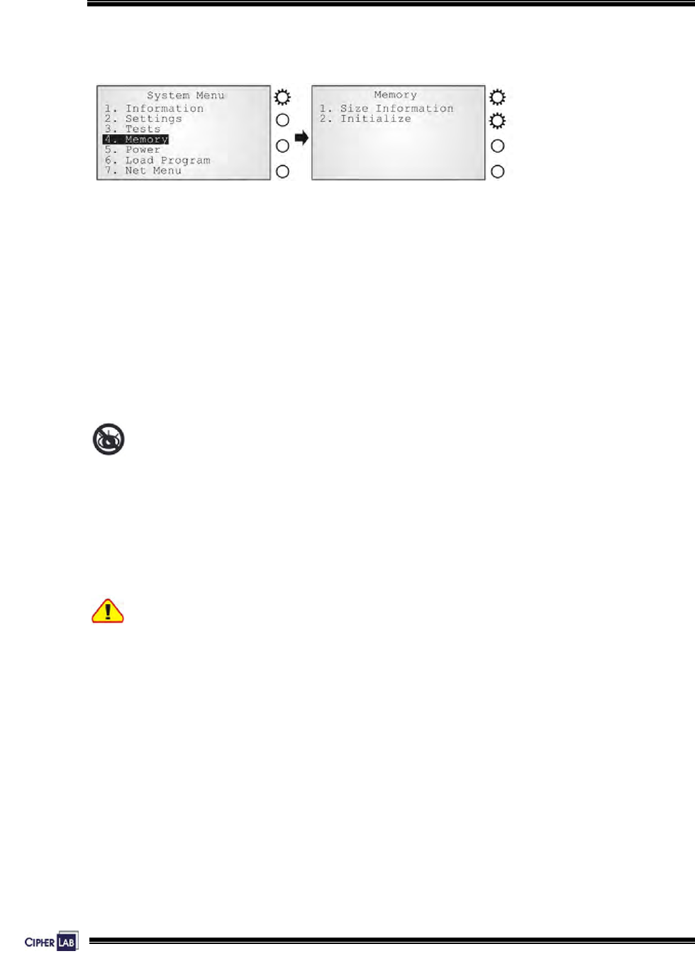
4.3.4 Memory
Screen 11: System Menu> 4. Memory
Memory > Size information
Here provides information regarding the data and program memory:
z Base RAM (SRAM for data memory)
z Memory Card (SRAM for data memory)
z Flash (for program memory)
Without a screen, this is not available on the 5000 terminals.
Memory > Initialize
Perform task initializing the data memory (Base RAM or Memory Card).
Warning! The contents of the data memory (SRAM) will be wiped out after memory
initialization.
52
Configuring 5000/5100:
System Menu
4.3.5 Power
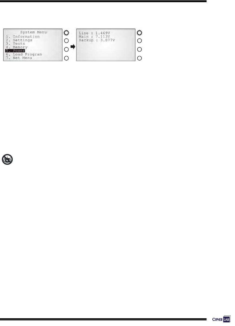
Screen 12: System Menu> 5. Power
Here shows current voltage consumption for Line / Main / Backup.
z Line: Line power (DC) status.
z Main: Main battery status.
The battery pack is a standby power source when line power is down.
z Backup: Backup battery status.
The button cell is used to retain data in SRAM and maintain RTC.
Without a screen, this is not available on the 5000 terminals.
53
Configuring 5000/5100:
System Menu
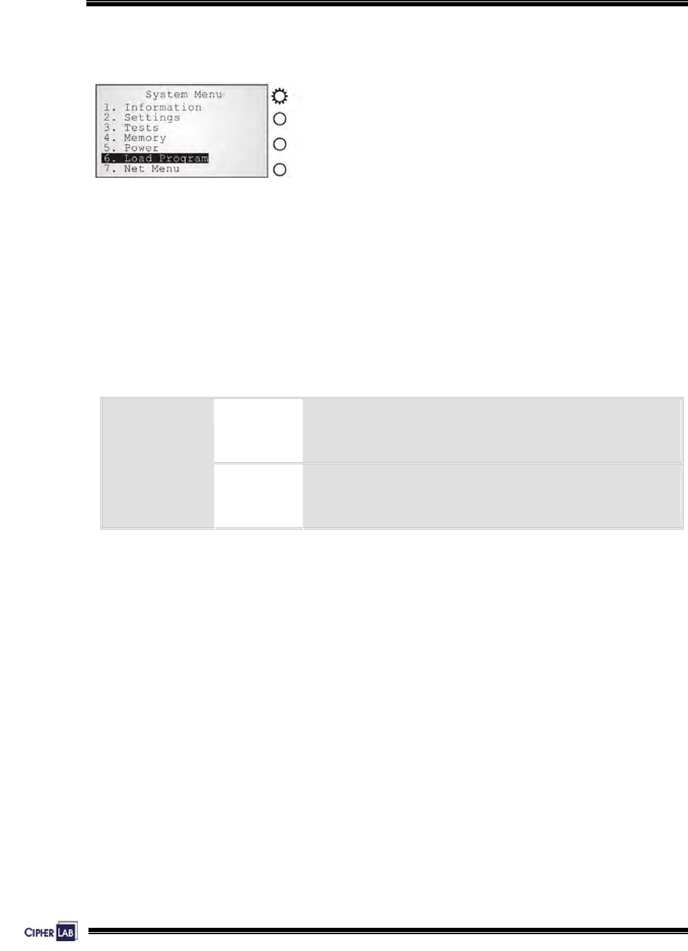
4.3.6 Load Program
Screen 13: System Menu> 6. Load Program
The terminal must be configured correctly for downloading either of the following:
z Program update
z New application program
z Font file (only RS-232 interface is allowed)
RS-232 Default parameters are 115200, none, 8, 1.
The communication parameters at PC end should be
set accordingly.
Interfaces:
Ethernet
See System Menu> Net Menu> Download via TCP/IP
Table 19: Downloading interfaces
Results
z Success: the new program or font file will be activated right after downloading.
z Failure: the terminal will resume to the current application program or font
54
Configuring 5000/5100:
System Menu
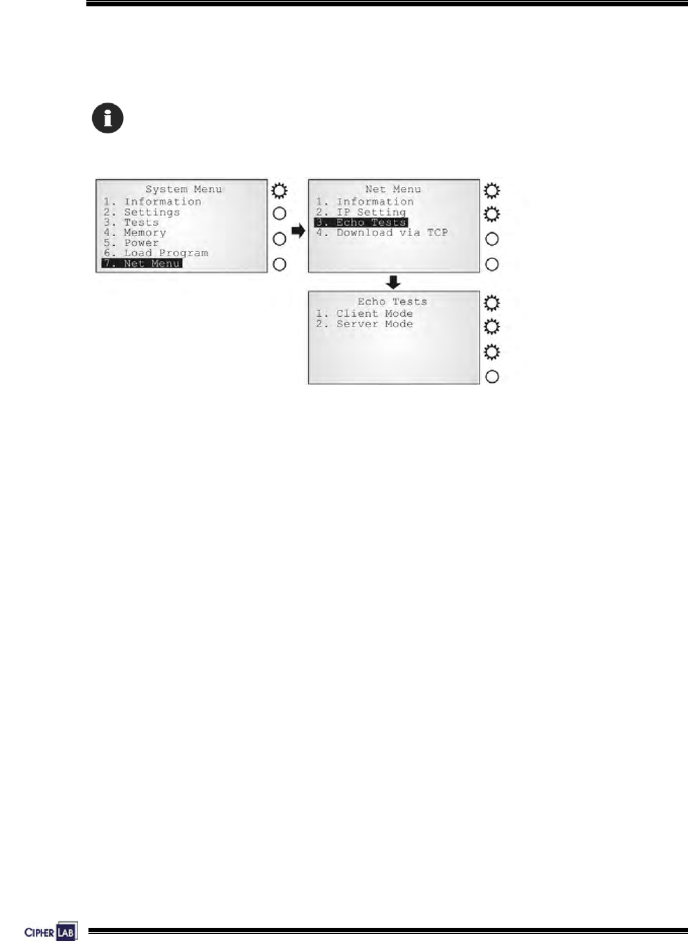
4.3.7 NET Menu
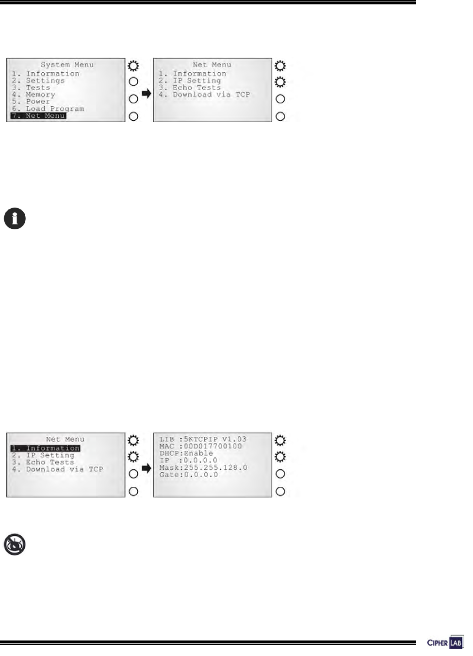
Screen 14: System Menu> 7. Net Menu
This submenu is for IEEE 802.3 10/100Base-T Ethernet networking, and is available
only when an Ethernet card is installed. Parameters must be configured correctly.
The menu can only be shown when the 5kTCPIP.LIB is linked.
Net Menu > Information
Information of network configuration can be viewed here.
z LIB: Version of 5KTCPIP.LIB
z MAC: MAC ID of the installed Ethernet (TCP/IP) module
z DHCP: DHCP being enabled or disabled
z IP: IP address of the terminal
z Mask: Subnet Mask
z Gate: Default Gateway
Screen 15: System Menu> 7. Net Menu> 1. Information
Without a screen, this is not available on the 5000 terminals.
55
Configuring 5000/5100:
System Menu
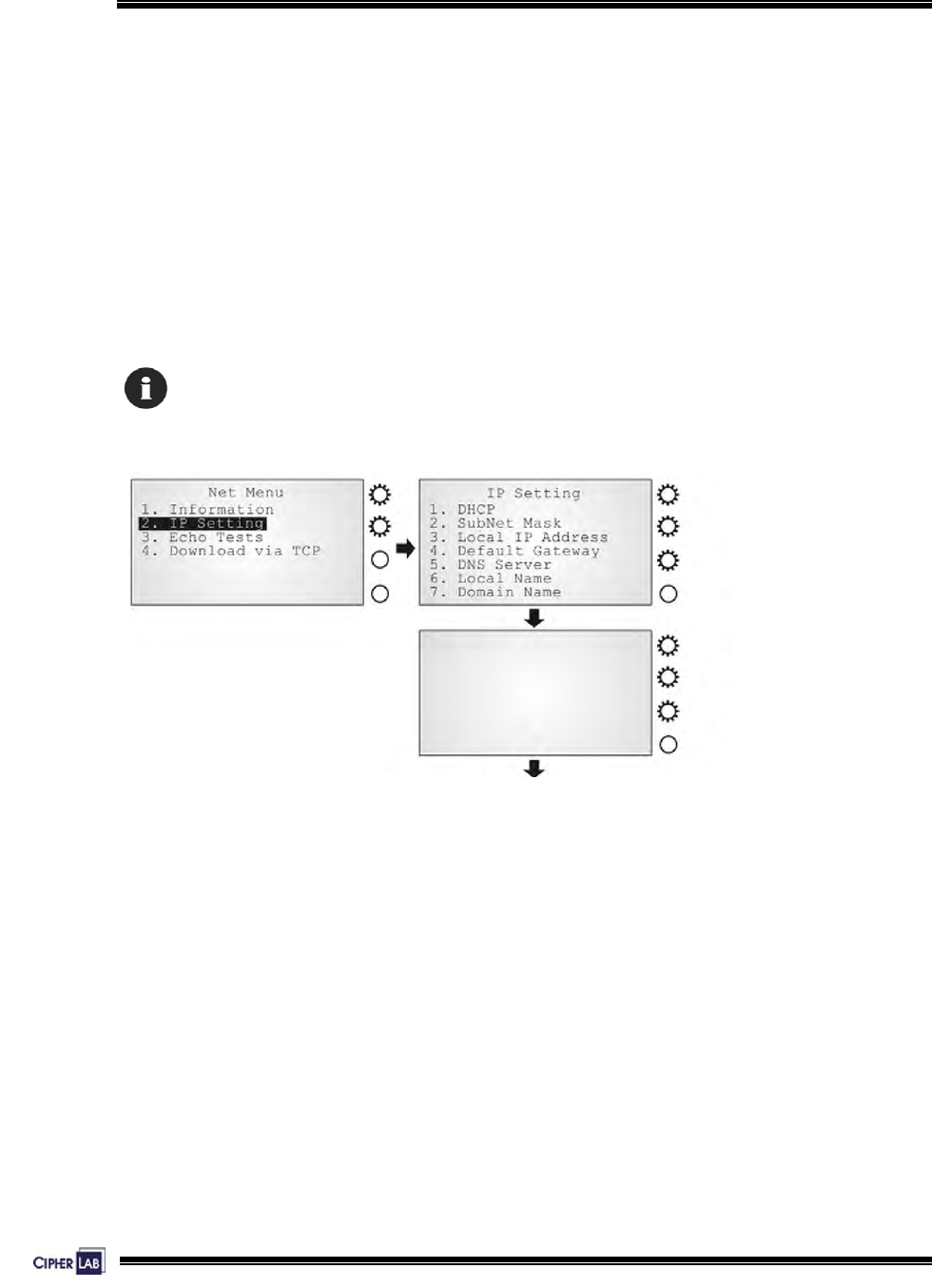
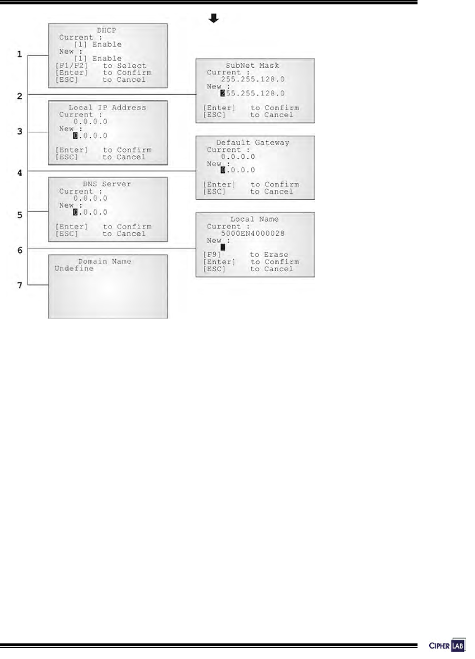
Net Menu > IP Setting
Set network parameters:
z DHCP: Options – Enable or Disable
z SubNet Mask: Enter a new Mask IP, if necessary.
z Local IP Address: Enter a new address for the terminal, if necessary.
z Default Gateway: Enter a new address for the default Gateway, if necessary.
z DNS Server: Enter a new address for the DNS server, if necessary.
z Local Name: Enter a name for identifying the terminal.
z Domain Name: The domain name of the host is shown here.
All of the setting could be obtained form DHCP server if DHCP is activated
56
Configuring 5000/5100:
System Menu
Screen 16: System Menu> 7. Net Menu> 2. IP Setting
57
Configuring 5000/5100:
System Menu
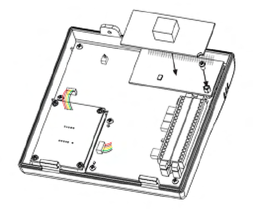
Net Menu > Echo Tests
Echo tests are used for verify connectivity. Press [ESC] to stop and exit the test.
You also need a test utility on PC to test the networking.
Screen 17: System Menu> 7. Net Menu> 3. Echo Tests
58
Configuring 5000/5100:
System Menu
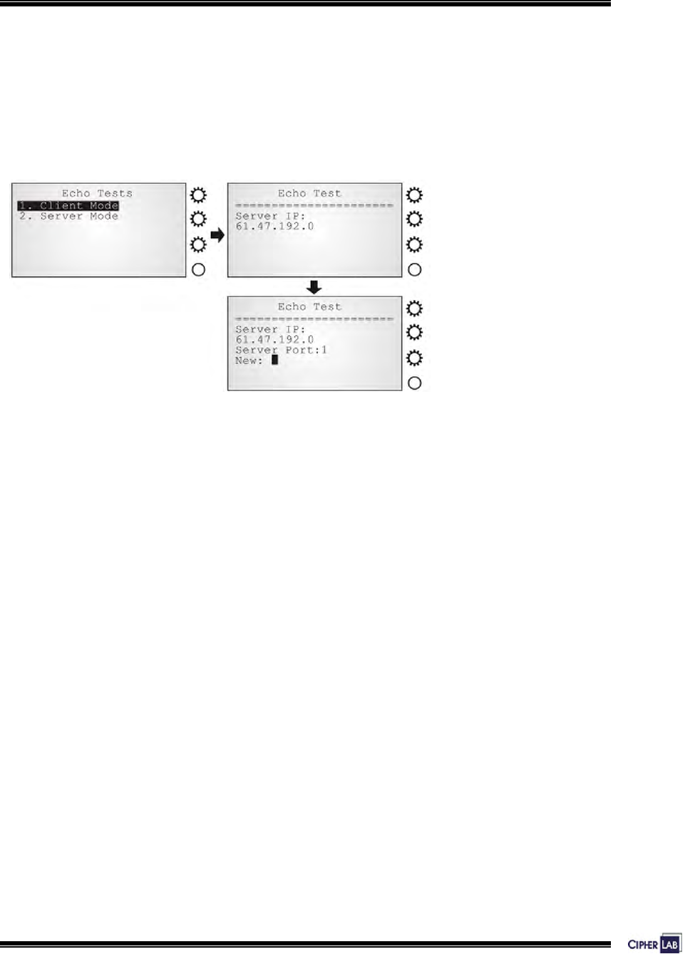
z Client Mode: Set the terminal as a client.
Enter the IP address of a server that connection is desired.
Followed by an attempt to make connection with the access point.
z Server Mode: Set the terminal as a server.
Followed by an attempt to make connection with the access point.
Screen 18: System Menu> 7. Net Menu> 3. Echo Tests: Client Mode
59
Configuring 5000/5100:
System Menu
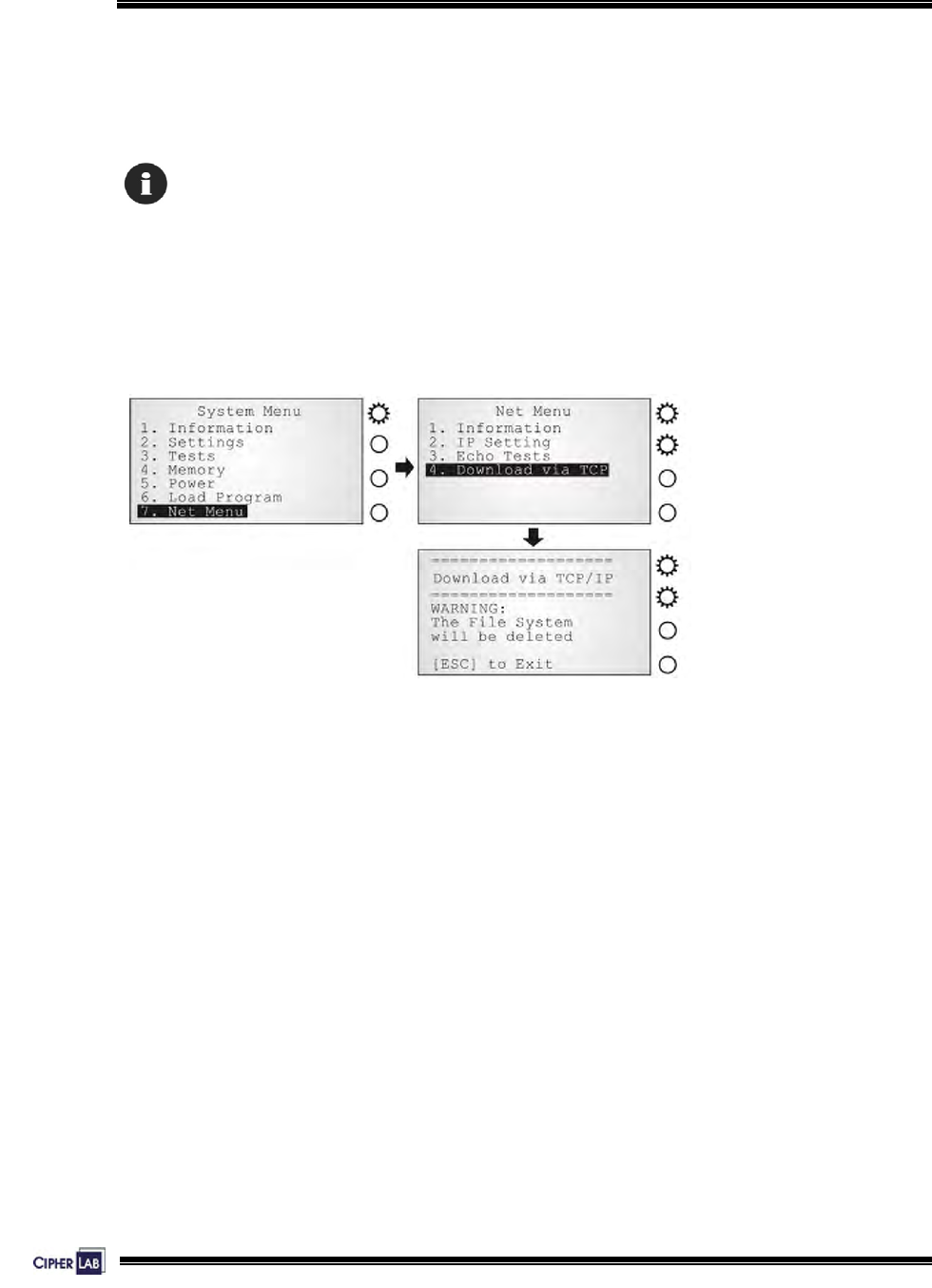
Net Menu > Download via TCP/IP
If an Ethernet card is installed, the terminal can download new application program or
program update via TCP/IP.
You also need a downloading utility on PC to download program through network.
Results
z Success: the new program will be activated right after downloading.
z Failure: the terminal will resume to the current application program
Screen 19: System Menu> 7. Net Menu> 4. Download via TCP/IP
60
Configuring 5000/5100:
Program Manager
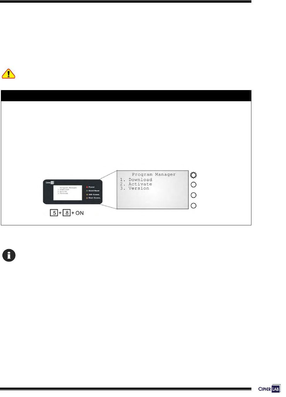
4.4 Program Manager
The 5000/5100 terminals support multiple applications and languages. In the menu of
Program Manager, it can download up to seven programs and one of them is made
active.
Warning! The Program Manager menu is NOT for the use of any end users.
How to access the Program Manager?
1. Lift the upper enclosure by unscrewing the two screws on top of the terminal.
2. Disconnect BOTH the line power and main battery.
3. Re-connect the main battery and simultaneously press [5] + [8] from the keyboard.
4. The Program Manager menu is displayed on the LCD screen as shown below.
5. Re-connect the line power when configuration is done.
Figure 25: Program Manager menu
Program Manager Menu, which is generated by 51pm.shx, is unavailable by default.
Please download 51pm.shx in the System Manu first.
61
Configuring 5000/5100:
Program Manager
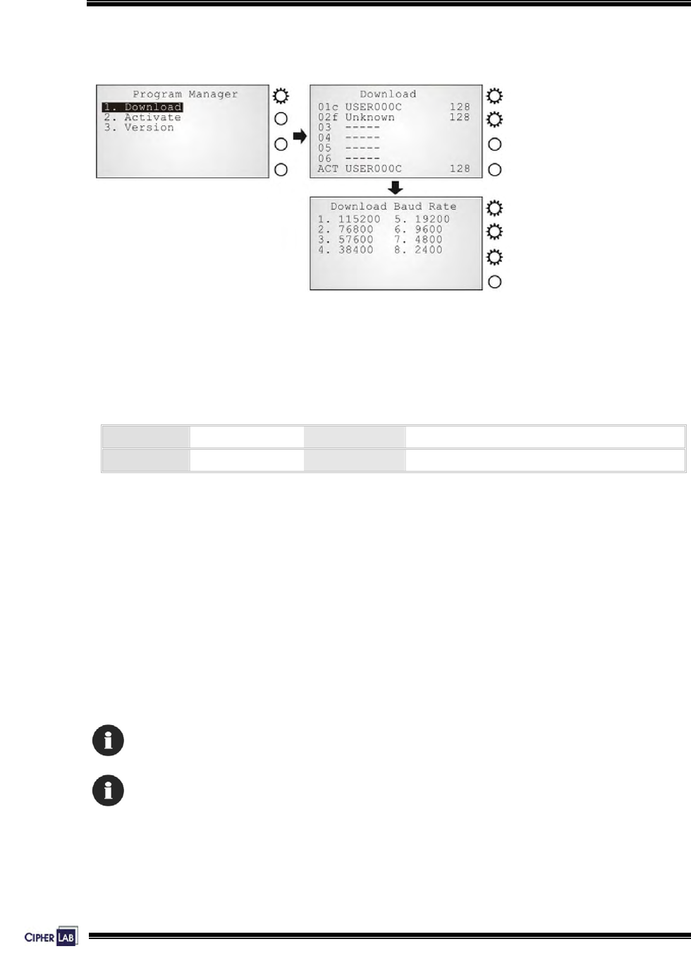
4.4.1 Download
Screen 20: Program Manager> 1. Download
Multiple programs as well as custom font file can be downloaded through RS-232
interface. There is a full list of programs and font file that are currently stored in the
terminal as follows.
01 ~ 06 File Name Volume Press [1 ~ 6] + [Enter]
ACT File Name Volume [7] + [Enter] or [F6] + [F2]
Table 20: Listing of multiple programs and font
The terminal can store up to seven programs (including the one in active memory)
and one font file (may not be shown in this list).
z Spare application programs (max. 6): baud rate selectable
z Active application program (1): default baud rate 115200, none, 8, 1
z Font file (1): default baud rate 115200, none, 8, 1
A slot number followed by “c”: the program is written by C language.
A slot number followed by “f”: this is a font file.
Only RS-232 interface is allowed.

62
Configuring 5000/5100:
Program Manager
Spare application programs
Empty slot:
1. Select an empty slot by pressing the corresponding number and then [Enter].
2. Select baud rate for downloading. Set matching parameters at PC end.
3. Connect cable and wait connecting…
4. To abort the action, press [ESC]. Then press [ESC] again to return to the menu.
Occupied slot:
If no available slots, you’ll have to replace one program with the new one.
1. Select a program that you want to delete by pressing the corresponding number
and then [Enter].
2. The program information is displayed on the screen. Press [Alpha] to enter the
capital mode. Then press [C].
3. Select baud rate for downloading. Set matching parameters at PC end.
4. Connect cable and wait connecting…
5. To abort the action, press [ESC]. Then press [ESC] again to return to the menu.
From the menu, you’ll find the program is deleted but no new program is present.
If you simply want to delete a program, press [D] in step 2.
Table 21: Downloading spare programs
[C], [D]: press the keypad to produce C or D when in the capital mode A.

63
Configuring 5000/5100:
Program Manager
Active application program or font file
The active slot:
1. Select the active program (may be an empty slot) by pressing the corresponding
number (that is 7) and then [Enter].
2. Set matching parameters at PC end: 115200, none, 8, 1
3. Connect cable and wait connecting…
4. If the downloaded program is an application, it will replace the active program and
come into effect immediately.
5. If it is a font file, then the current active program is still in use.
Table 22: Downloading active program or font
No font file will replace the active application program.
The new font file may not be shown in the program list if all slots are taken by
application programs, but you can view font information under System Menu>
Settings> Font.
>> Also see Section 4.3.2 Settings
64
Configuring 5000/5100:
Program Manager
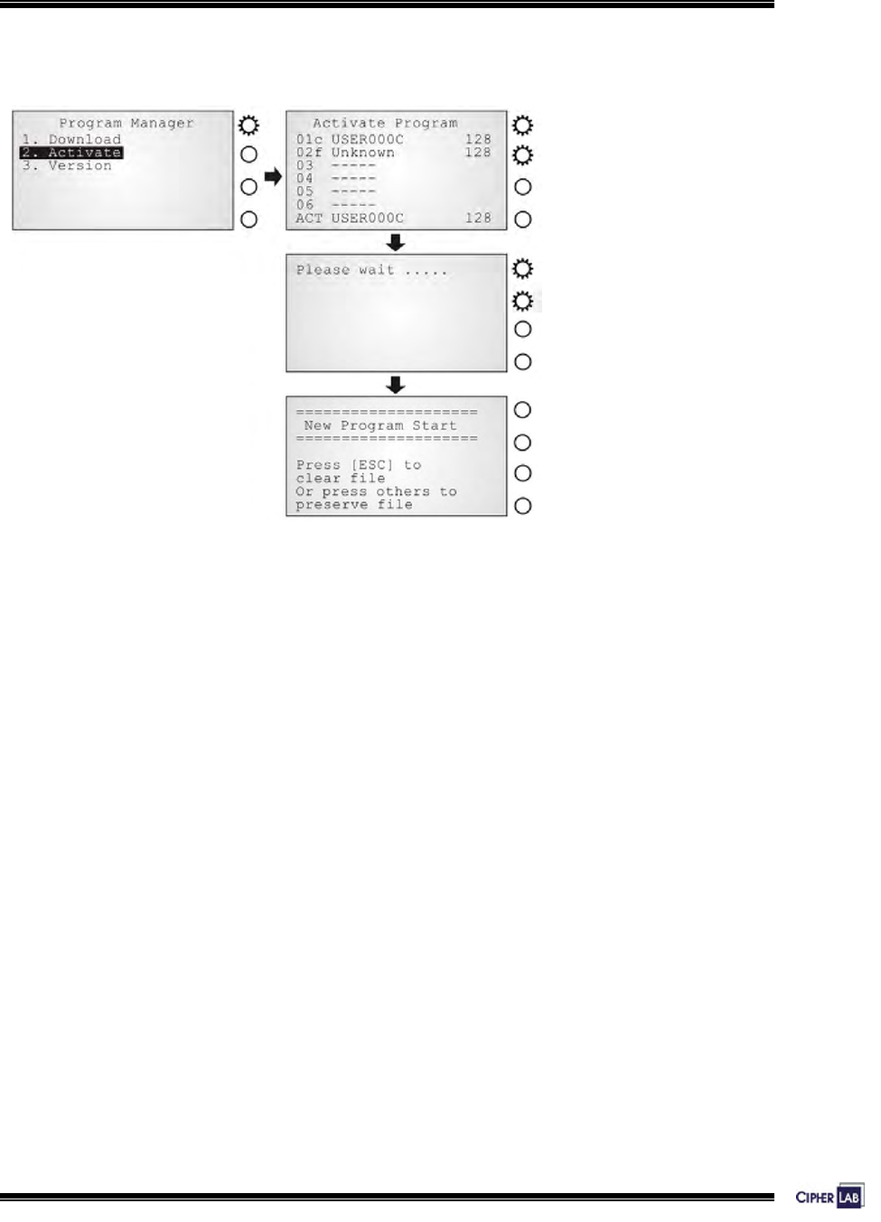
4.4.2 Activate
Screen 21: Program Manager> 2. Activate
The list shows the entire spare programs stored in the terminal. From the list, you can
select from 01 to 06 and activate one of them.
z When an application program is activated, it will be copied to the active memory
and replace the old one.
The <New Program Start> screen instructs that “Press [ESC] to clear file”. It
means the file system in the SRAM will be cleared out when pressing [ESC]. Then
there will be no data (transactions, settings, etc.) stored in the terminal when the
new program comes into effect. To keep the data, simply press any other key.
z When a font file is activated, it will replace the system font. The active application
program will remain intact.

65
Configuring 5000/5100:
Program Manager
4.4.3 Version
Here provides information about the version of Program Manager.
Without a screen, this is not available on the 5000 terminals.
66
Configuring 5000/5100:
Kernel Menu
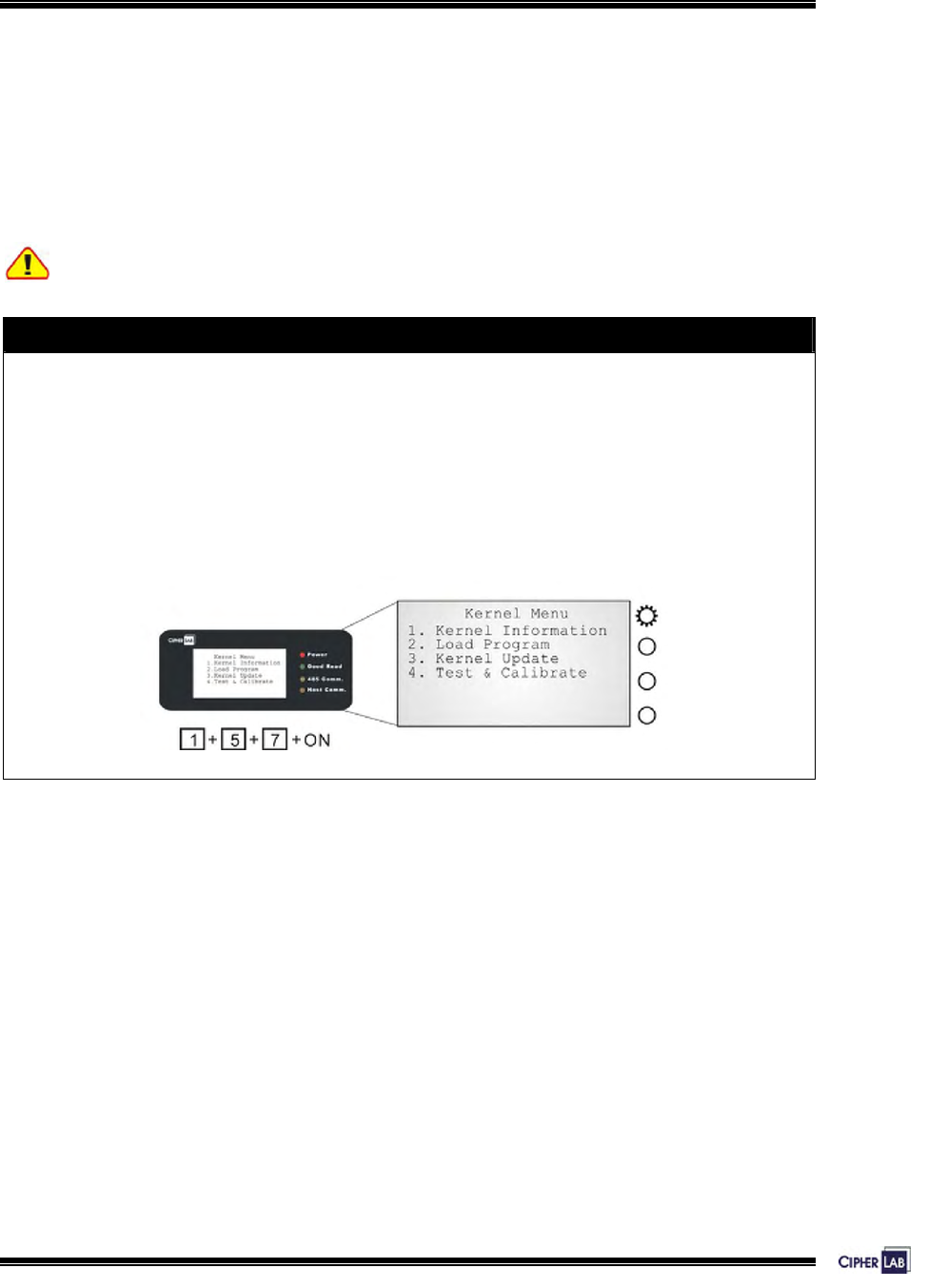
4.5 Kernel Menu
The Kernel Menu resides in the innermost core of the system. It has the highest
security and is always protected by the system. When the application program is
corrupted and the System Menu fails, the Kernel Menu provides an access to fix the
system.
Warning! The Kernel Menu is NOT for the use of any end users.
How to access the Kernel Menu?
1. Lift the upper enclosure by unscrewing the two screws on top of the terminal.
2. Disconnect BOTH the line power and main battery.
3. Re-connect the main battery and simultaneously press [1] + [5] + [7] from the
keyboard.
4. The Kernel Menu is displayed on the LCD screen as shown below.
5. Re-connect the line power when configuration is done.
Figure 26: Kernel Menu
67
Configuring 5000/5100:
Kernel Menu
4.5.1 Information
The information provided here helps diagnose the system.
z H/W: Hardware version
z S/N: A unique serial number for the device
z M/D: Manufacturing date
z KNL: Kernel version
z DEV: Code for optional hardware configurations, i.e. 1700
1 7 0 0
Type of Reader Module Type of LAN Module Reserved Reserved
0= none
1= EM
2= Mifare
0= none
7= Ethernet
Table 23: Device code explained
Without a screen, this is not available on the 5000 terminals.

68
Configuring 5000/5100:
Kernel Menu
4.5.2 Load Program
The terminal must be configured correctly for downloading either of the following:
z Program update
z New application program
z Font file
1. Connect RS-232 cable.
2. Set communication parameters at PC end: 115200, none, 8, 1.
3. Enter Kernel Menu> Load Program.
The system is ready to download the program to the active slot.
Only RS-232 interface is allowed.
Results
z Success: the new program or font file will be activated right after downloading.
z Failure: the terminal will resume to the current application program or font

69
Configuring 5000/5100:
Kernel Menu
4.5.3 Kernel Update
The Kernel might be changed for improving performance or other reasons, and an
update is necessary.
1. Connect cable.
2. Set communication parameters at PC end: 115200, none, 8, 1.
3. Enter Kernel Menu> Kernel Update.
The system is ready to update the Kernel firmware.
Only RS-232 interface is allowed.
4.5.4 Test & Calibrate
These tools are provided for manufacturing use. No user definition is allowed.
z Burn-In Test
z Calibrate RTC
Warning! This is NOT for the use of any end users.
70
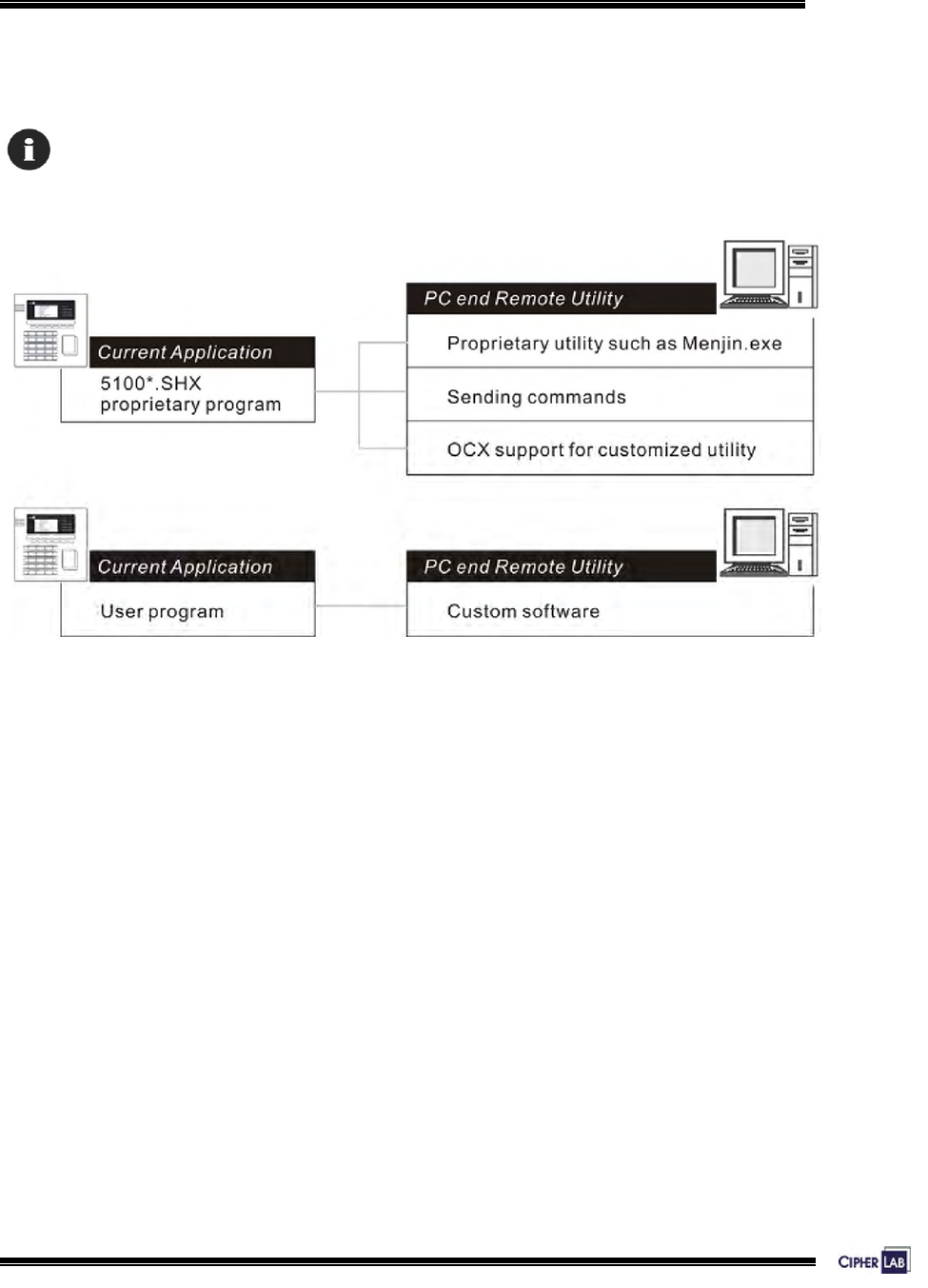
5. MANAGING 5000/5100
Depending on the application program downloaded to the terminals, managing the
5000/5100 terminals at PC end can be very flexible and simple.
For details, please see relevant documents such as Programming Guide.
Figure 27: Remote management

71
Managing 5000/5100
5.1 For proprietary applications
For any preloaded application program (5100*.SHX), we provide several ways for
managing the terminal from PC end.
Management Utilities
This is application dependant. For example, Menjin.exe is developed for Access
Control application.
Commands
Sending commands serves as an alternative to manage the terminals.
OCX Support
Customized utilities can be developed in an efficient way.
5.2 For custom applications
For user-defined application programs, management software is to be developed by
your own system programmers.
Programming Support
For development of custom application software, proprietary BASIC or C complier is
available through licensing agreement, as well as libraries.
72
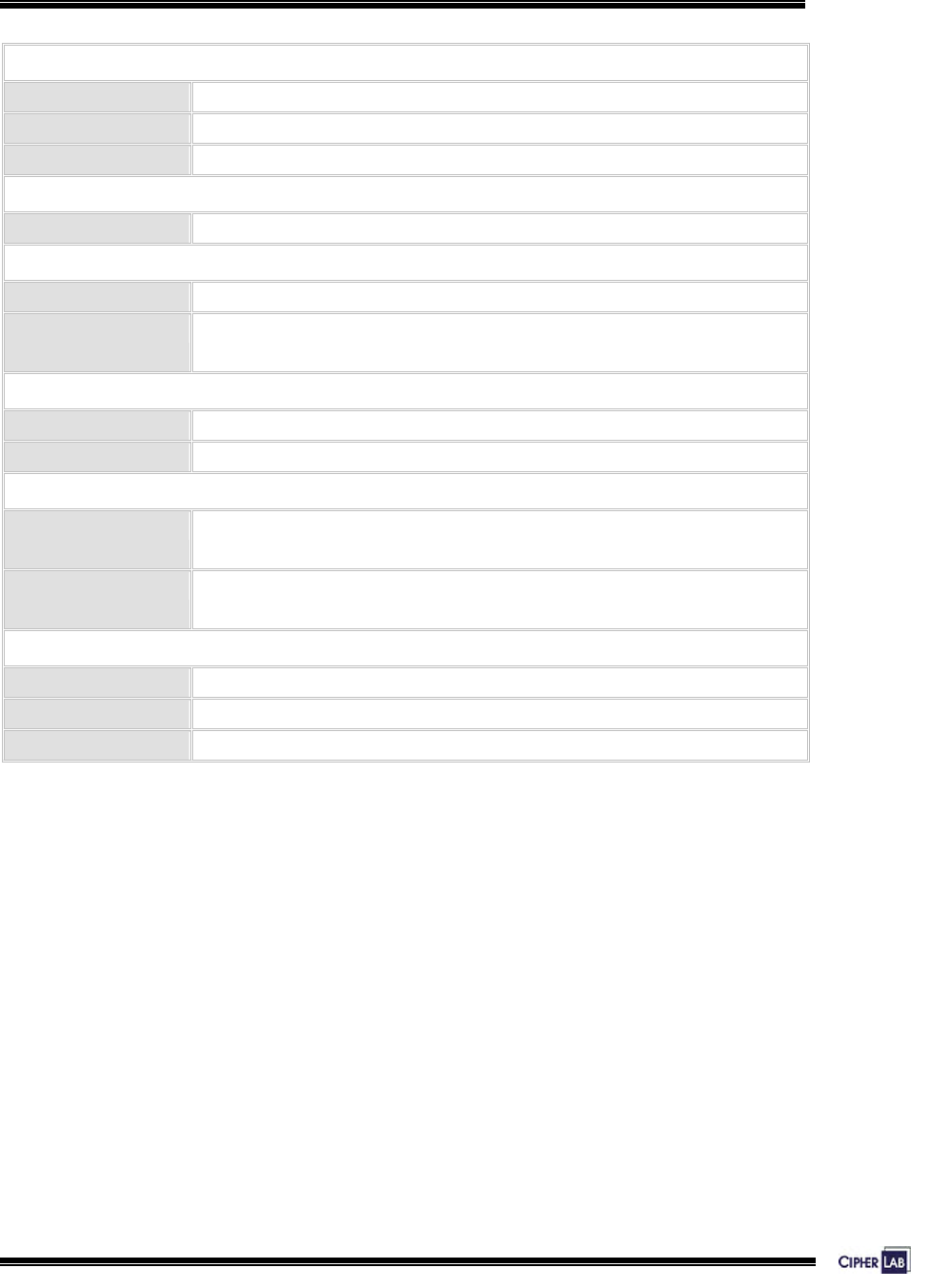
SPECIFICATIONS
Power
Line power: 12 V ± 5% DC at 1000 mA
Main battery: Rechargeable 7.4 V, 2000 mAh Li-ion battery pack (optional)
Backup battery: Rechargeable 3.0 V, 7 mAh Lithium button cell
CPU
16-bit CPU: Tunable clock, up to 22 MHz
Memory
Flash: 2 MB program memory
SRAM: Standard 256 KB on-board data memory
Memory card (optional)
Programming Support
Components: OCX
Compilers: BASIC and C
Environment
Humidity: Operating: 20% to 90% non-condensing
Storage: 10% to 95% non-condensing
Temperature: Operating: 0 to 45 °C
Storage: -20 to 60 °C
EMC certified
FCC Class B
CE Class B
C-Tick Class B

73
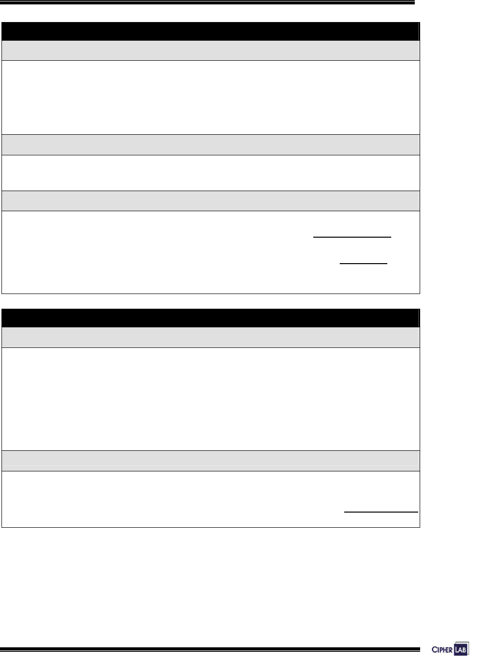
Specifications
Enclosure
Material & Color: ABS plastic
Black
Dimensions: 150 mm (L) x 150 mm (W) x 50 mm (H)
Weight: Approx. 1.6 Kg (including one battery pack)
Input Devices
Reader: Built-in RFID reader, Mifare or EM type (optional)
Also allow for one external TTL RS-232 reader
Keyboard: 21 keys rubber including 6 function keys, backlit, programmable
One external Mini Din connector provided by keyboard module
Display
Graphic LCD: 128 x 64 pixels, LED backlit, programmable –
4 lines by 8 characters for Chinese characters
Indicators
LED: 4 LEDs, programmable
Buzzer: Low power transducer type, 1 KHz to 4 KHz, programmable
Interfaces
RS-232: Master-to-Slave connection
RS-485: Peer-to-Peer connection
RJ-45 port: Ethernet networking (optional)
Digital Inputs/outputs
DI: 4 sets of DI signal
DO: 4 sets of DO signal
74
TROUBLESHOOTING
The terminal cannot accept valid cards…
Regarding power –
Check if the power adaptor is plugged into a wall outlet.
Check if the outlet is working.
If the problem persists, check if the wiring inside the terminal is correct and secured.
Regarding memory –
Check if memory buffer is full. Then clean buffer by downloading data to a computer.
Regarding the reader –
Check if the selected reader type in your application matches the default setting.
>> Also see Section 4.3.1 Information: DEV
Check if the reader is working.
>> Also see Section 4.3.3 Tests: RFID
If the problem persists, re-connect the power and perform test.
The terminal cannot transmit or receive data to and from a host…
For RS-232 connection –
Check if the RS-232 connection is secured and properly wired.
Check if parameters are correct.
Make sure the serial port parameters on the host are configured to match the default
serial parameters.
If the problem persists, check if the wiring inside the terminal is correct and secured.
For Ethernet networking –
Check if the Ethernet cable is secured at both ends.
Check if parameters are correct.
>> Also see Section 4.3.7 NET Menu
75
Troubleshooting
The keyboard input seems not working properly…
Test keyboard.
>> Also see Section 4.3.3 Tests: Keyboard
If the problem persists, re-connect the power and perform test.
The external devices controlled by DI/DO signals are not working properly…
Check if the device is properly wired to the terminal blocks.
If the problem persists, re-connect the power and perform test.
About abnormal response…
The LEDs or LCD seem not working properly –
Test components.
>> Also see Section 4.3.3 Tests: LCD & LED
If the problem persists, re-connect the power and perform test.
The buzzer seems not working properly –
Test audible indicators.
>> Also see Section 4.3.3 Tests: Buzzer
If the problem persists, re-connect the power and perform test.
The terminal seems not working properly –
First upload all data to a computer, and then test memory.
>> Also see Section 4.3.3 Tests: Memory
If the problem persists, re-connect the power and perform test.
76
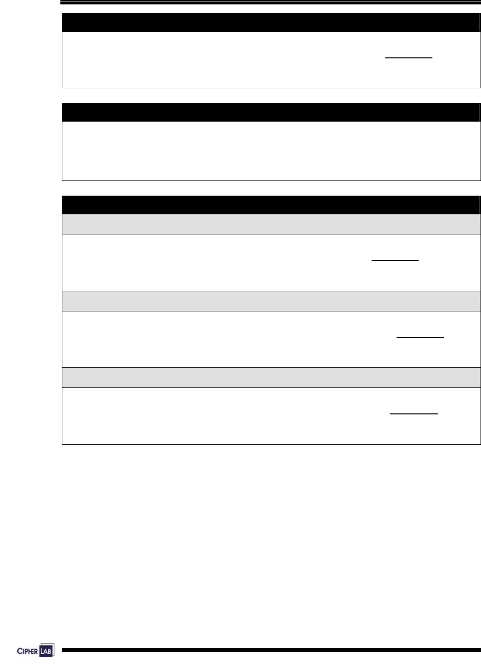
APPENDIX I – MOUNTING TEMPLATE
This mounting template is provided in actual size (1:1 scale).
1. Place this paper on the place you desire to mount the terminal.
2. Use paper tape to attach it on the surface.
3. Then use a power drill to drill holes on the four corners.
The size of these holes is 6mm in diameter and 21mm in depth.
Make sure that your printout doesn’t zoom in/out during printing.
Figure 28: Mounting template
Installing WLAN card
You may have to install the WLAN card to the terminal by yourself. If you have
installed a memory card, attach the WLAN card on top of it then.
Align the pinholes at the back of the card to the pins on the main PCB.
Press down the card flatly. Be careful not to bend or distort any pins.
Then apply the screw to screw down to the pole.
Figure 13: Installing WLAN card

IEEE 802.11b
When the 802.11b module is installed, the terminal can easily connect to legacy
networks through access points (APs). Roaming among different networks is possible.
IEEE 802.11b is an industrial standard for Wireless Local Area Networking (WLAN),
which enables wireless communications over a long distance.
The speed of connection between two wireless devices will vary with range and signal
quality. To maintain a reliable connection, the 802.11b system automatically fallback
from 11 Mbps to 5.5, 2 or 1 Mbps as range increases or signal quality decreases.
An 802.11b network can operate in the following two modes:
Infrastructure mode - Wireless devices can communicate with each other or can
communicate with wired networks through APs.
Ad-hoc mode - Wireless devices or stations can communicate directly to each other,
without the use of APs.
802.11b Specification
Frequency Range: 2.4 ~ 2.483 GHz
Modulation: DSSS with DBPSK (1 Mbps), DQPSK (2 Mbps), CCK
Protocols: IP/TCP/UDP
Maximum Output Power: 100 mW
Data rate: 11, 5.5, 2, 1 Mbps auto-fallback
Coverage: 250 meters line-of-sight
Connected devices: Peer-to-Peer (no access point)
Server-to-Client (access point required)
Standard: IEEE 802.11b, interoperable with Wi-Fi devices

Net Menu
Re-connect the main battery and simultaneously press [5] + [7] + [9] from the keyboard.
Press [7] into Net Manu
This submenu is for IEEE 802.11b wireless networking. Parameters must be
configured correctly.
Note: This menu is available only when the 802.11b module is installed.
802.11b Menu: Settings: Default Values
DHCP Enable
SubNet Mask 255.255.128.0
Local IP Address 0.0.0.0
Default Gateway 0.0.0.0
DNS Server 0.0.0.0
IP Setting
Domain Name blank
Local Name blank
Domain Name blank
SS ID blank
System Scale Medium
Power Saving Enable
WLAN Setting
Preamble Long
Authentication Open System
WEP Menu Disable
Security
EAP Menu Disable

¾ Net Menu > Information
Information of network configuration can be viewed here.
MAC: MAC ID of the 802.11b module
DHCP: DHCP being enabled or disabled
IP: IP address of the terminal
Mask: Subnet Mask
Gate: Default Gateway
¾ Net Menu > IP Setting
Set general network parameters.
DHCP: Options - Enable or Disable
SubNet Mask: Enter a new Mask IP, if necessary.
Local IP Address: Enter a new address for the terminal, if necessary.
Default Gateway: Enter a new address for the default Gateway, if
necessary.
DNS Server: Enter a new address for the DNS server, if necessary.
Domain Name: The domain name of the host is shown here.
Note: All of the setting could be obtained form DHCP server if DHCP is activated.
¾ Net Menu > WLAN Setting
802.11b system can operate in two modes (1) Ad-hoc mode: peer-to-peer, and (2)
Infrastructure mode: point to multi-point through access points.
Set the following parameters.
Local Name: Enter a name for identifying the terminal.
Domain Name: The domain name of the host is shown here.
SS ID: This refers to Service Set ID or Identifier.
The terminal can ONLY communicate with access
points that have the same SS ID
System Scale: This refers to Access Point Density.
Options - [1] Low [2] Medium [3] High

The value you set must match that set for the access
point.
Power Saving: This refers to the low power consumption mode.
Options - Enable or Disable
The value you set must match that set for the access
point.
Preamble: Options - [1] Long [2] Short [3] Both
The value you set must match that set for the access
point.
¾ Net Menu > Security
Set up or modify security parameters:
Authentication
[1] Open System:
[0] Share Key:
Default authentication type
This requires implementing WEP key.
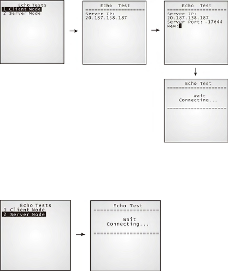
¾ Net Menu > Echo Tests
Echo tests are used for verifying connectivity to make sure the terminal is within
coverage.
Client Mode: Set the terminal as a client.
Enter the IP address of a server that connection is
desired.
It is followed by an attempt to make connection with
APs.
Server Mode: Set the terminal as a server.
It is followed by an attempt to make connection with
APs.