CipherLab 8260 Terminal User Manual manual
CipherLab Co., Ltd. Terminal manual
UserManual.wiki
>
CipherLab
>
8260 User Manual
manual
Navigation menu
Upload a User Manual
Namespaces
Wiki Guide
HTML
PDF
Info
Views
User Manual
Discussion / Help
Navigation
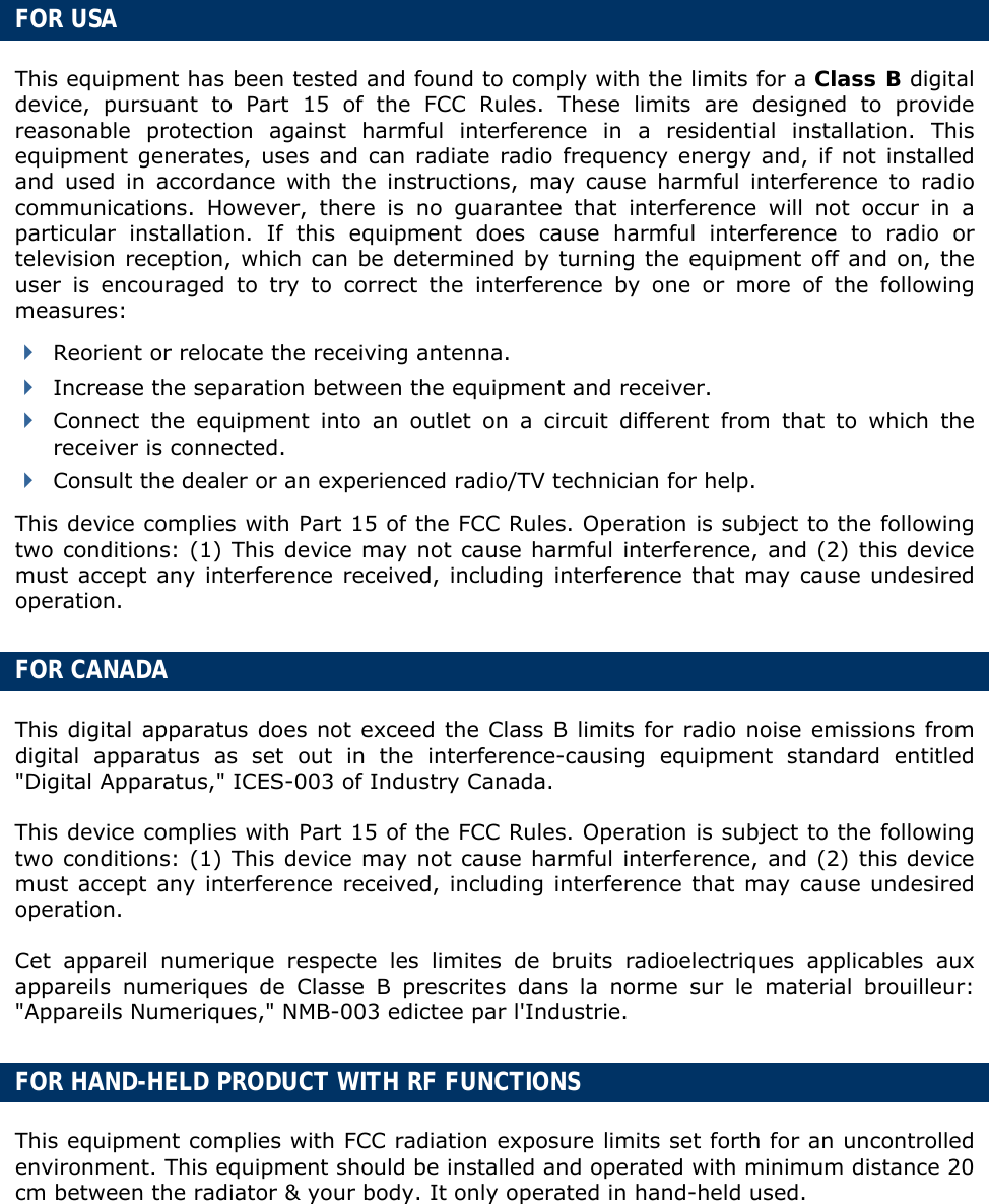
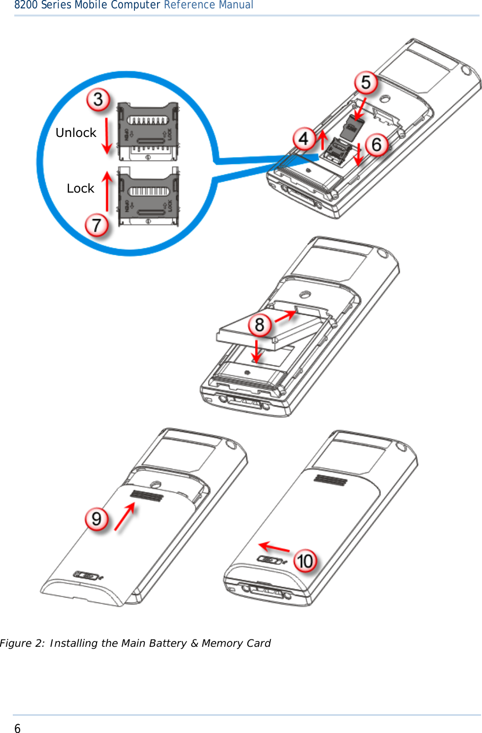
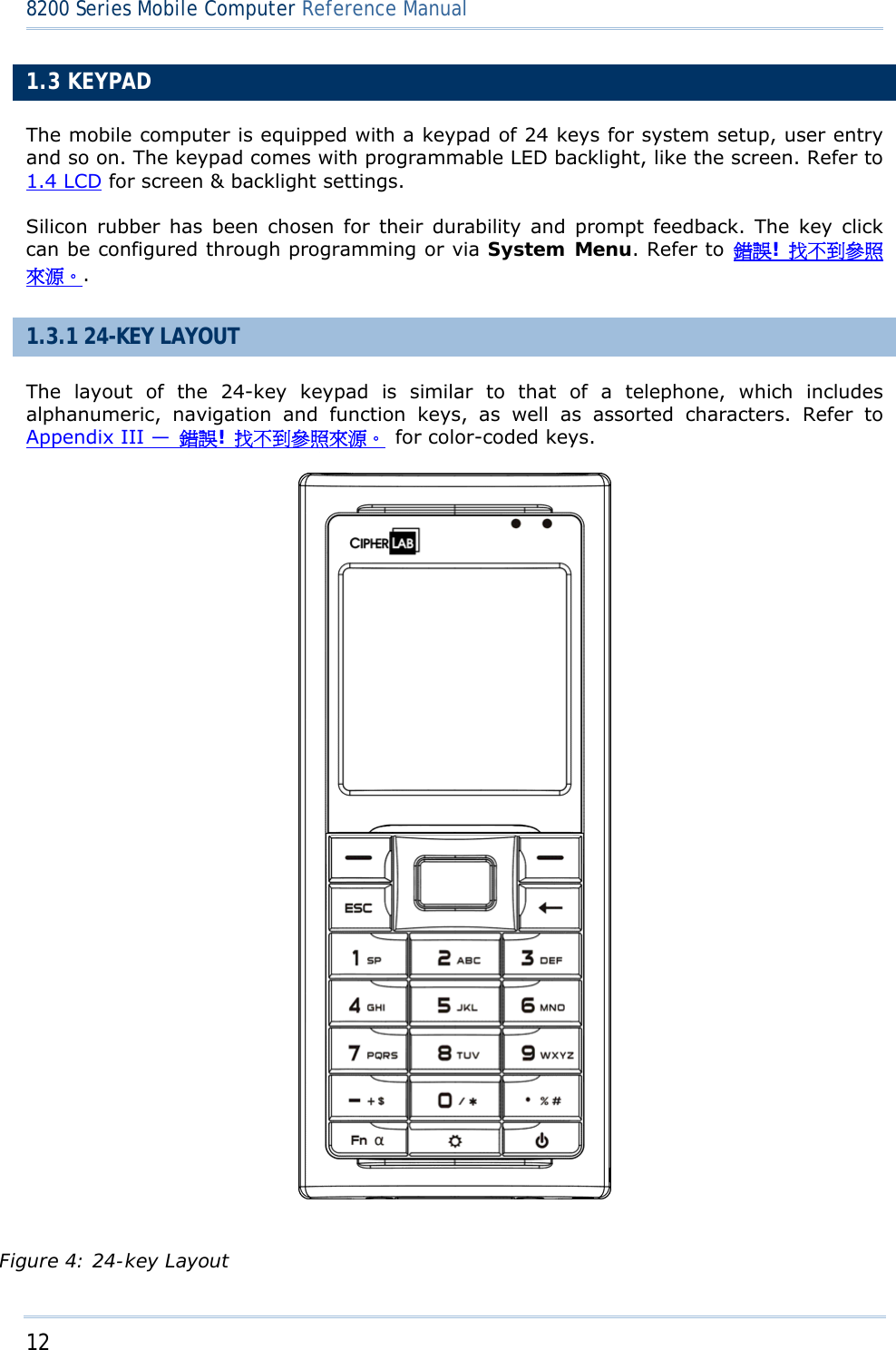
![3 錯誤! 使用 [常用] 索引標籤將 Heading 1 套用到您想要在此處顯示的文字。 FEATURES Ergonomic design — ruggedized yet streamlined, with wristband for secure hold Built tough to survive drop test and sealed against moisture/dust to IP 52 Up to 8 GB high capacity memory card (microSDHC) supported Flexible wireless solutions — Bluetooth or 802.11b/g FTP client support — 802.11b/g Graphic monochrome LCD supports double-byte characters and bitmap graphics Programmable feedback includes speaker, LED indicators and vibrator Quick link to any backend database through MIRROR Emulator programs for VT100/220 and IBM 5250 emulation Easy customization of data collection applications through FORGE Application Generator (AG) programs for preloaded AG Runtime, batch and WLAN versions available Programming support includes BASIC & C compilers Accessories include pistol grip. INSIDE THE PACKAGE The following items are included in the package. Save the box and packaging material for future use in case you need to store or ship the mobile computer. 8200 Series mobile computer Rechargeable Li-ion battery pack Wristband Standard USB cable Universal power adaptor Product CD Quick Start Guide](https://usermanual.wiki/CipherLab/8260/User-Guide-1487786-Page-11.png)
![5 錯誤! 使用 [常用] 索引標籤將 Heading 1 套用到您想要在此處顯示的文字。 Note: For a new battery, make sure it is fully charged before use. Always prepare a spare battery pack, especially when you are on the road.](https://usermanual.wiki/CipherLab/8260/User-Guide-1487786-Page-13.png)
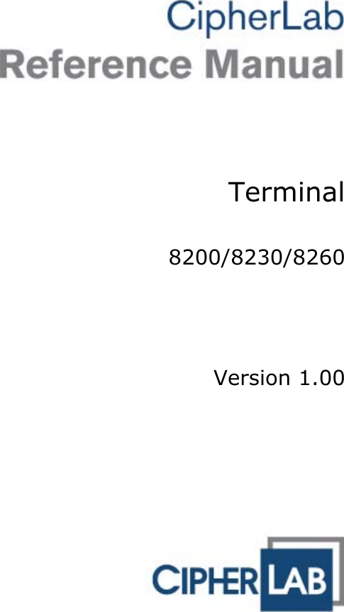
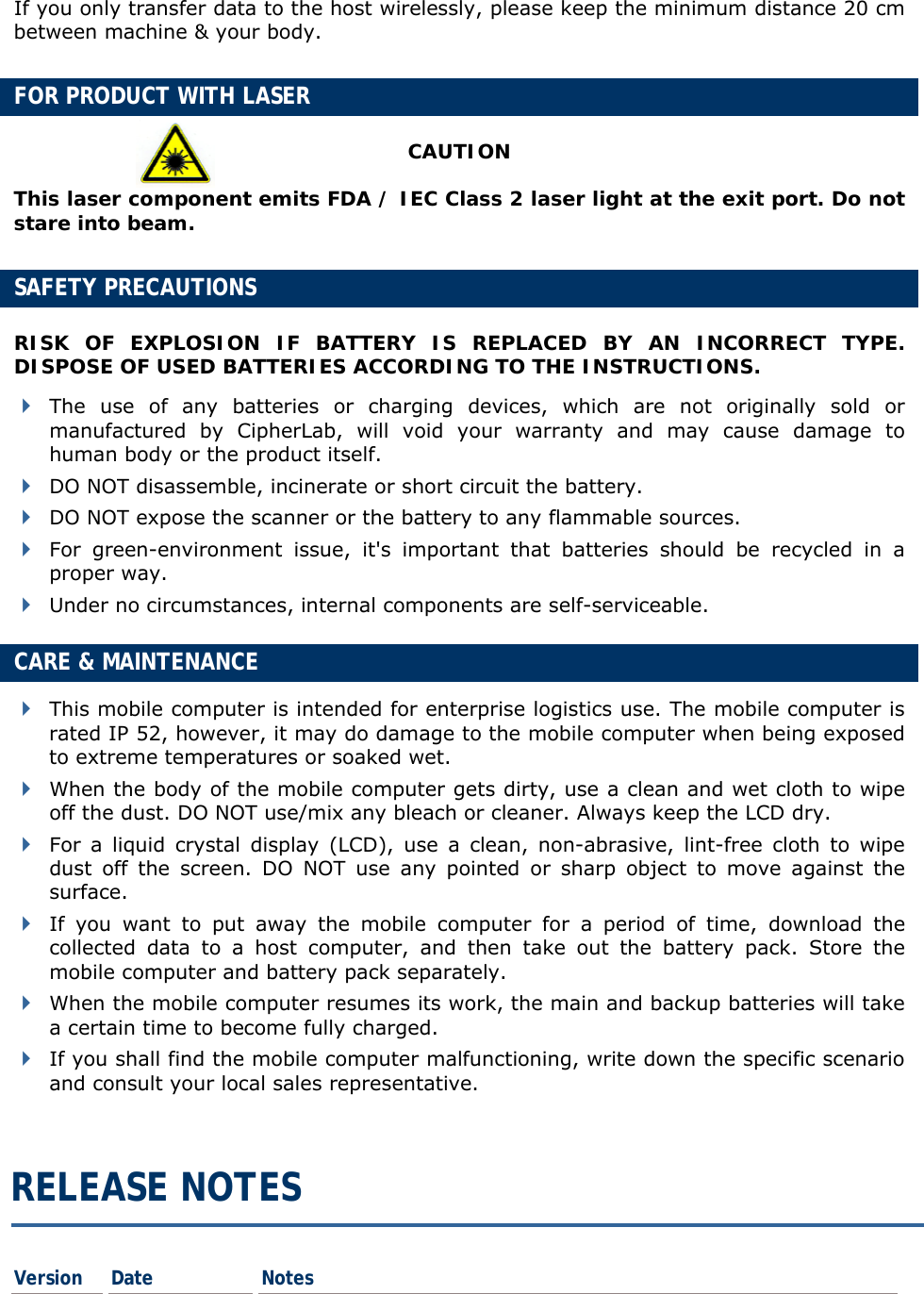
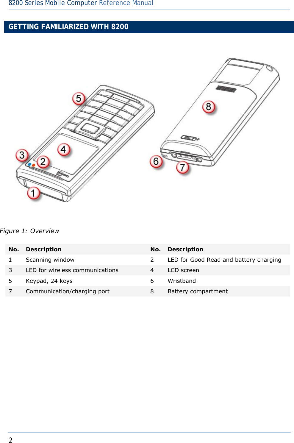
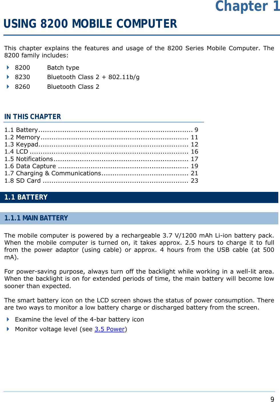
![7 錯誤! 使用 [常用] 索引標籤將 Heading 1 套用到您想要在此處顯示的文字。 INSTALLING PISTOL GRIP This contoured pistol grip enables intuitive trigger-and-scan operation, which is very helpful in scan intensive applications. When a pistol grip is necessary, install it to the mobile computer by following these steps: 1) Hold the mobile computer still and slide the release latch to the right to unlock the battery cover. 2) Slide off the battery cover. 3) Insert the pistol grip into place (is like replacing the battery cover). 4) Slide the release latch to the left to lock it firmly, and turn on the mobile computer to test the trigger. Figure 3: Installing the Pistol Grip](https://usermanual.wiki/CipherLab/8260/User-Guide-1487786-Page-15.png)
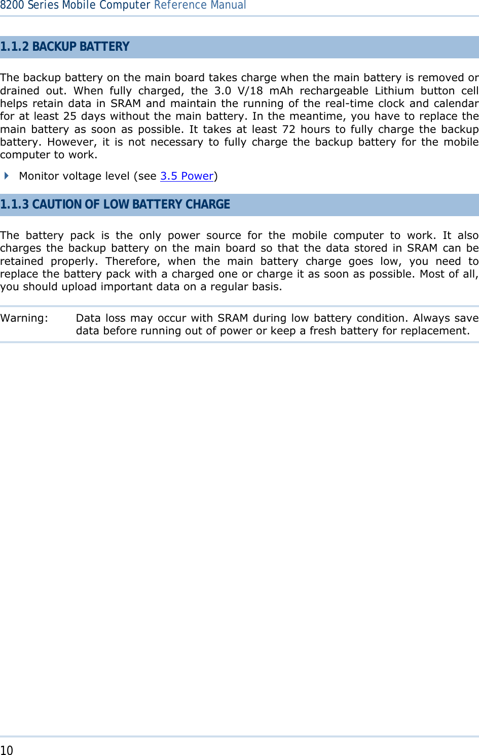
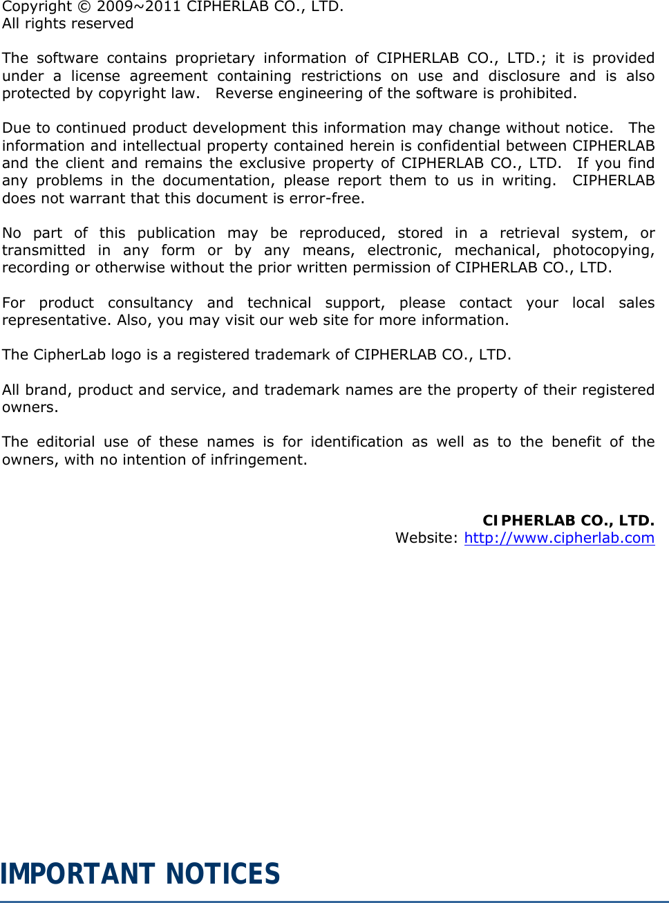
![11 Chapter 1 錯誤! 使用 [常用] 索引標籤將 Heading 1 套用到您想要在此處顯示的文字。1.2 MEMORY The collected data can be sent back to a host computer immediately over wireless networks, or stored in memory (SRAM) and upload later. The mobile computer is equipped with a calendar chip for accurate time/date logging. When the main battery is removed or drained, the backup battery on the main board is to retain the contents of SRAM and maintain the running of real-time clock and calendar for at least 25 days, on condition that the backup battery has already been fully charged. If you want to put away the mobile computer for a couple of days, you should be aware that data loss occurs when both the main and backup batteries discharge completely. Therefore, it is necessary to upload data and files before putting away the mobile computer! 1.2.1 READ-ONLY MEMORY (ROM) 8 megabytes flash memory for storing core, OS, application programs, font, etc. 1.2.2 RANDOM-ACCESS MEMORY (RAM) Options include 4 or 8 megabytes SRAM for storing data. Its contents will be retained by the backup battery. 1.2.3 SD CARD Secure Digital (SD) card is a flash memory data storage device. Up to 8 GB high capacity memory card (microSDHC) is supported. Refer to Inserting Battery & Memory Card for how to insert the microSD or microSDHC card. For more details, refer to 1.8 SD Card. Note: (1) When SD card is present, the card icon will appear on the screen and flash while being accessed. (2) For an SD card that has never been used on 8200, a message like “Found New SD Card” will be displayed allowing users to scan the card for memory check. If the action is canceled then, memory check can still be performed via System Menu — 錯誤! 找不到參照來源。.](https://usermanual.wiki/CipherLab/8260/User-Guide-1487786-Page-19.png)
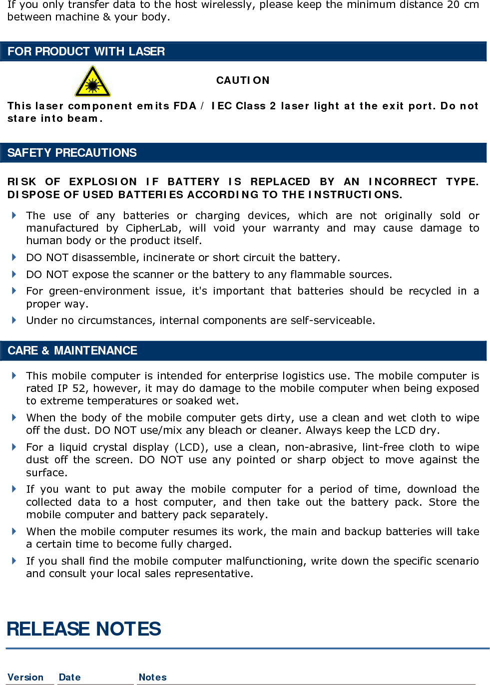
![13 Chapter 1 錯誤! 使用 [常用] 索引標籤將 Heading 1 套用到您想要在此處顯示的文字。This alphanumeric keypad is set to numeric mode by default. The [Fn α] key serves as a toggle among numeric, alpha (lower-case alphabetic), and ALPHA (upper-case alphabetic) input modes, as well as function mode. Note: It is not necessary to hold down the [Fn α] key. The associated icon will appear on the lower-left corner of the screen in a sequence as shown below. Status Icon Function/Alpha Key Input Mode (none) N/A Numbers A Press [Fn α] one time Upper-case alphabetic a Press [Fn α] two times Lower-case alphabetic F Press [Fn α] three times Function Mode When in alpha mode, it takes turns to show alphabets and number when you keep pressing the same key; each press must not exceed one second. For example, keep pressing the number key [2], it will take turns to show “A”, “B”, “C” or “2” for upper-case, and “a”, “b”, “c” or “2” for lower-case. When you first press the number key [2], it will produce the letter “A” or “a”. When you press the number key [2] twice (the time interval must not exceed one second), it will produce the letter “B” or “b”. When you press the number key [2] three times (the time interval between each press must not exceed one second), it will produce the letter “C” or “c”. When you press the number key [2] four times (the time interval between each press must not exceed one second), it will produce the number “2”. In order to get the desired character, you will need to press the same key, one to four times (the time interval between each press must not exceed one second). Only when you stop pressing the same key for longer than one second or you press another key, will the system send the real key code to the application program. When in function mode, the [Fn α] key works with a number key. Press the [Fn α] key three times, and its associated icon F will be displayed on the screen. Press the second key, say [5], to complete the key combination and access the function [F5]. Press [Fn α] again and the icon F will go off.](https://usermanual.wiki/CipherLab/8260/User-Guide-1487786-Page-21.png)
![14 8200 Series Mobile Computer Reference Manual Below briefly describes the functions of common keys on the mobile computer. SCAN The yellow key is used to work as the ENTER key by default. When the reader function is enabled, this yellow key is set to trigger the scan engine so that it can read a barcode. ENTER The two keys on each upper side of the SCAN key are user-friendly and convenient for either right-handed or left-handed operator. Normally, it is used for command execution or input confirmation. ESC (Escape) This key is on the left lower side of the SCAN key. Normally, it is used to stop and exit the current operation. Navigation Pad The 4-way navigation pad around the SCAN key is used to move the cursor left, up, down, or right. While pressing [ ], they can be used to adjust the luminosity and contrast of the screen backlight. Backspace This key is Backspace by default. If this key is being held down for more than one second, a clear code will be sent. Function/Alpha Key This key is a modifier key that requires pressing a second key to get the yellow-coded letter (A~Z) or symbol printed above the second key, or the function (F0~F9) of the second key. Icon Description A This icon appears when you press the [Fn α] key one time, indicating it is set to alphabetic mode for typing upper-case alphabetic letters. a This icon appears when you press the [Fn α] key two times, indicating it is set to alphabetic mode for typing lower-case alphabetic letters. F This icon appears when you press the [Fn α] key three times, indicating it is set to the function mode. Then, press another key ([0] ~ [9]) to get the desired function. To get the value of another key combination modified by the function key, keep pressing another key ([0] ~ [9]) to produce the result. To exit the function mode, press [Fn α] again and the icon will go off.](https://usermanual.wiki/CipherLab/8260/User-Guide-1487786-Page-22.png)
![15 Chapter 1 錯誤! 使用 [常用] 索引標籤將 Heading 1 套用到您想要在此處顯示的文字。Backlight Configuration Key This key is used to turn ON/OFF the backlight of the LCD and keypad. Also, while pressing [ ], the navigation keys can be used to adjust the luminosity and contrast of the screen backlight. Key Description [] + [Right] Press these keys at the same time to increase the contrast. [] + [Left] Press these keys at the same time to decrease the contrast. [] + [Up] Press these keys at the same time to increase the luminosity. [] + [Down] Press these keys at the same time to decrease the luminosity. Power Key In order to prevent an accidental press of the POWER key, you need to hold down this key for approximately 1.5 seconds to turn ON/OFF the mobile computer. Note: (1) Functionality of keys is application-dependent. The system will send the associated key code to the application program, and it is up to the application program to interpret the key code. (2) When a status icon appears on the screen, it indicates a certain mode is activated and it is not necessary to hold down the modifier key.](https://usermanual.wiki/CipherLab/8260/User-Guide-1487786-Page-23.png)
![16 8200 Series Mobile Computer Reference Manual 1.4 LCD The mobile computer comes with a FSTN graphic LCD, 160 by 160 pixels resolutions, which can be programmed to display text or graphics, such as specific font and company logo, to meet varying application needs. Options Font Size (pixels) Characters by lines English font Font size 6×8 (pixels) Font size 8×16 (pixels) 26 characters by 18 lines 20 characters by 9 lines Chinese font Font size 12×12 (pixels) Font size 16×16 (pixels) 13 characters by 12 lines 10 characters by 9 lines Other language fonts, company logo… Programmable Note: The bottom line (ICON_ZONE) is reserved to display status icons, such as the battery icon. 1.4.1 ADJUSTING THE BACKLIGHT The backlight of screen and keypad helps ease reading under dim environments. It can be turned on and adjusted decreasingly or increasingly by the following key combinations. Keep pressing the key combination until the luminosity or contrast is decreased or increased to a desired level. Alternatively, the luminosity and contrast can be configured through programming or via System Menu. Refer to 錯誤! 找不到參照來源。 and 錯誤! 找不到參照來源。. Note: Using backlight while on battery power will substantially reduce battery power. We suggest that you dim the backlight while working in a well-lit area or have it set to be automatically turned off when not in use. Key Combination Action [] Toggle ON/OFF the backlight [] + [Up] Turn ON the backlight and increase the luminosity of LCD [] + [Down] Turn ON the backlight and decrease the luminosity of LCD [] + [Right] Turn ON the backlight and increase the contrast of LCD [] + [Left] Turn ON the backlight and decrease the contrast of LCD Note: Hold down the first key, and keep pressing the second key for adjustment.](https://usermanual.wiki/CipherLab/8260/User-Guide-1487786-Page-24.png)
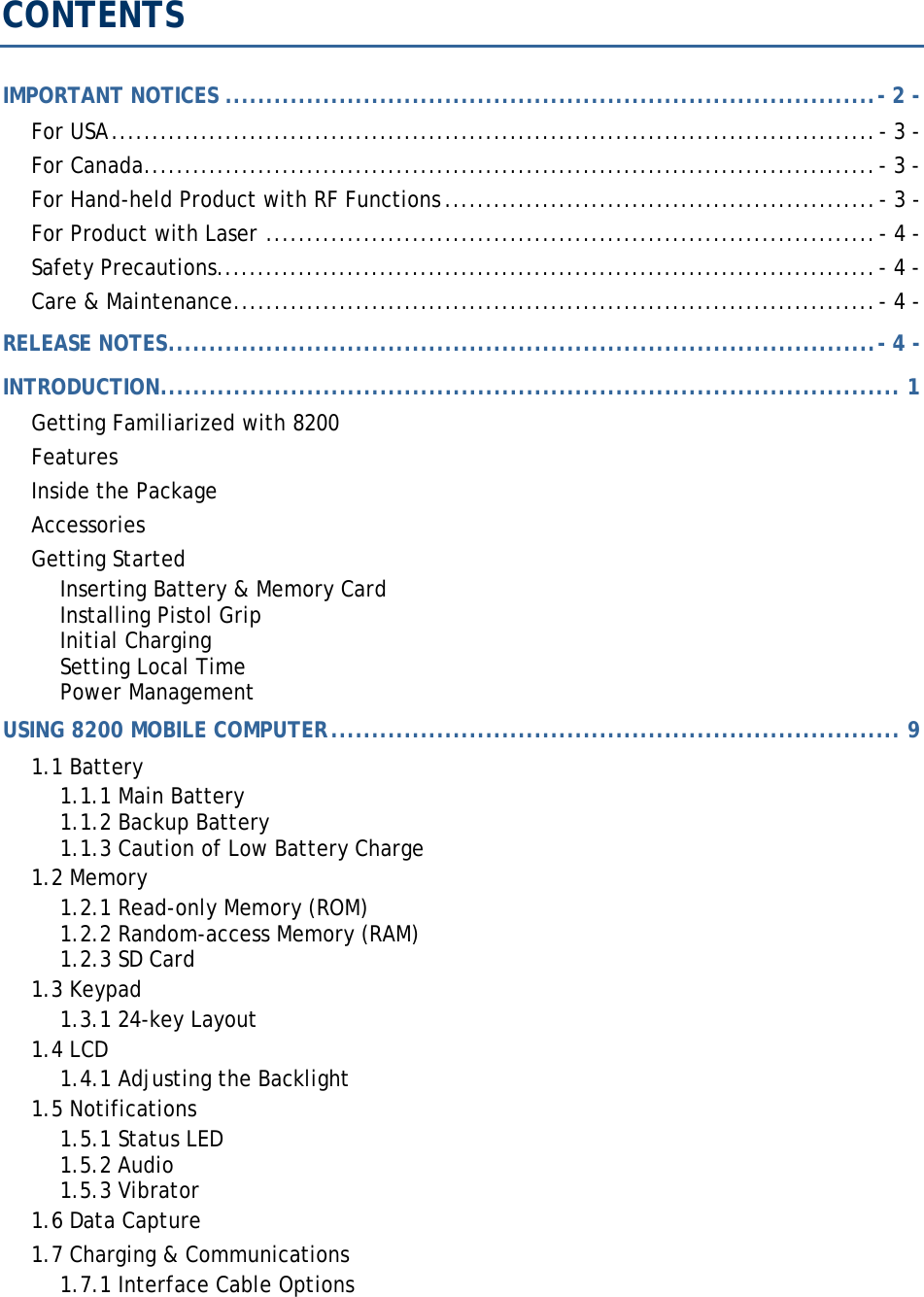
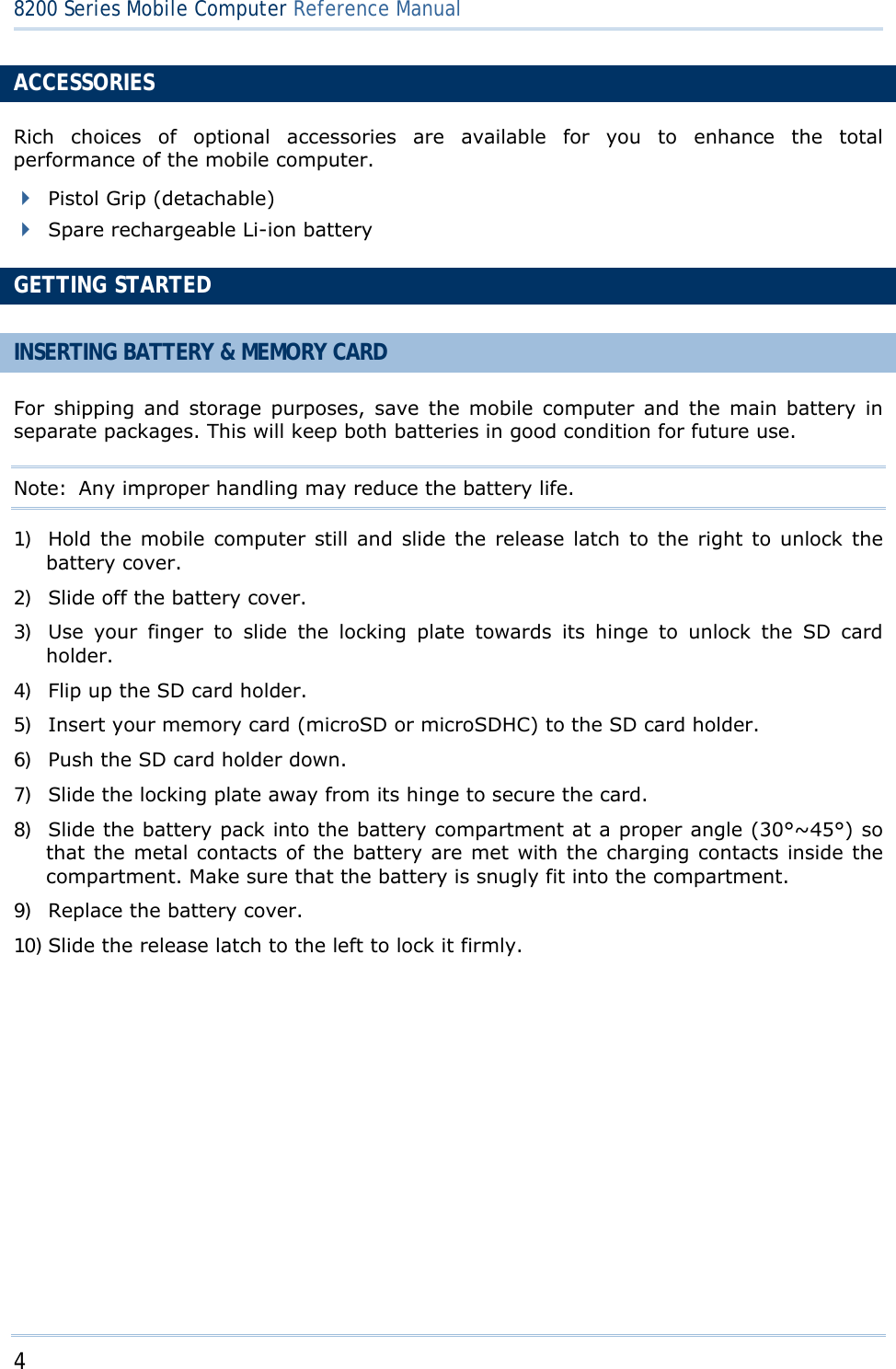
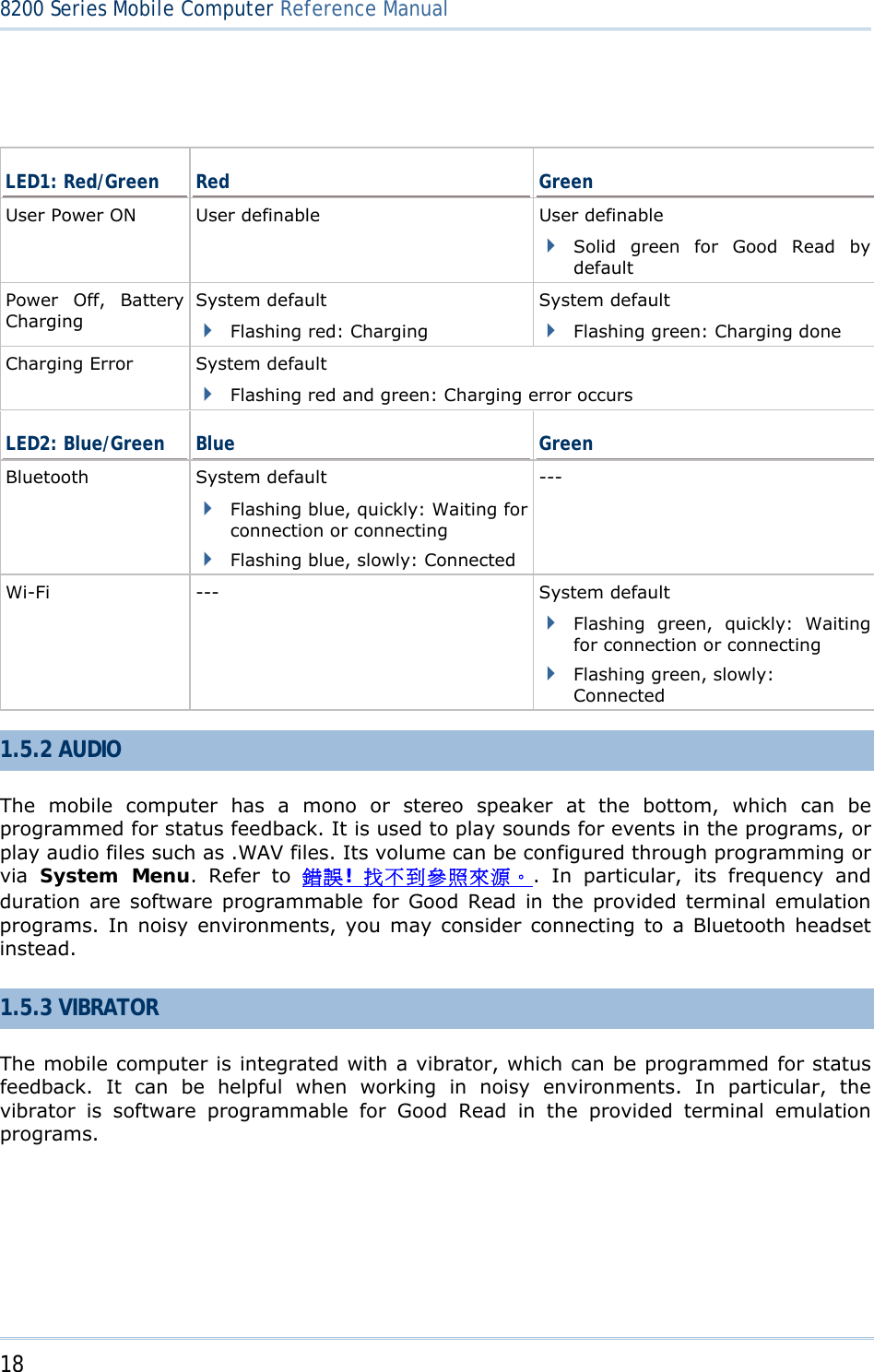
![17 Chapter 1 錯誤! 使用 [常用] 索引標籤將 Heading 1 套用到您想要在此處顯示的文字。1.5 NOTIFICATIONS 1.5.1 STATUS LED There are two dual-color LED indicators above the screen. Both can be programmed to provide information that helps diagnosing. For example, if you are using AG runtime, you will be informed of the scanning result immediately. LED1 is used for "Good Read" and will become solid green upon reading a barcode successfully. LED1 is used to provide information on the charging status and barcode decoding. LED2 is used to provide information on wireless communications. Figure 5: LED Indicators LED1 LED2](https://usermanual.wiki/CipherLab/8260/User-Guide-1487786-Page-25.png)
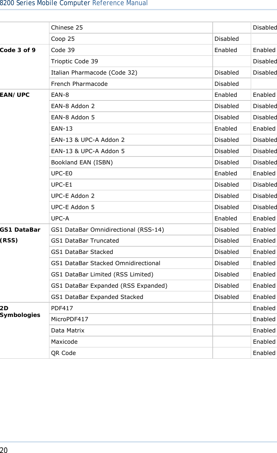
![19 Chapter 1 錯誤! 使用 [常用] 索引標籤將 Heading 1 套用到您想要在此處顯示的文字。1.6 DATA CAPTURE A wide variety of scan engines is available for delivering flexibility to meet different requirements. Depending on the scan engine integrated, the mobile computer is capable of scanning barcodes of a number of symbologies that are enabled by default while running the preloaded AG runtime. Refer to 3.3.1 Reader for functional test. If you need to scan barcodes that are encoded in a symbology, which is disabled by default in AG runtime, FORGE Application Generator (ForgeAG.exe) allows configuring symbology settings, as well as reader settings. First, enable the desired symbologies, and then, download the application settings to the mobile computer. Note: For details on configuring reader and symbology settings, please refer to the documentation of the software you use. Varying by the scan engine installed, the supported symbologies are listed below. 1D CCD scan engine 1D Laser scan engine 2D scan engine Note: In AG or CipherNet runtime, not all of the symbologies are enabled by default. Instead of running any of them, you can develop your own applications to control the scan engine for data collection. Symbologies Supported (Default Setting: Enable/Disable) CCD/Laser 2D Codabar Enabled Enabled Code 11 Enabled Code 93 Enabled Enabled Composite Code CC-A/B Disabled CC-C Disabled TCIF Linked Code 39 Enabled MSI Disabled Enabled Plessey Disabled Postal Codes Enabled Telepen Disabled Code 128 Code 128 Enabled Enabled GS1-128 (EAN-128) Enabled Enabled ISBT 128 Enabled Enabled Code 2 of 5 Industrial 25 (Discrete 25) Enabled Enabled Interleaved 25 Enabled Enabled Matrix 25 Disabled Disabled](https://usermanual.wiki/CipherLab/8260/User-Guide-1487786-Page-27.png)
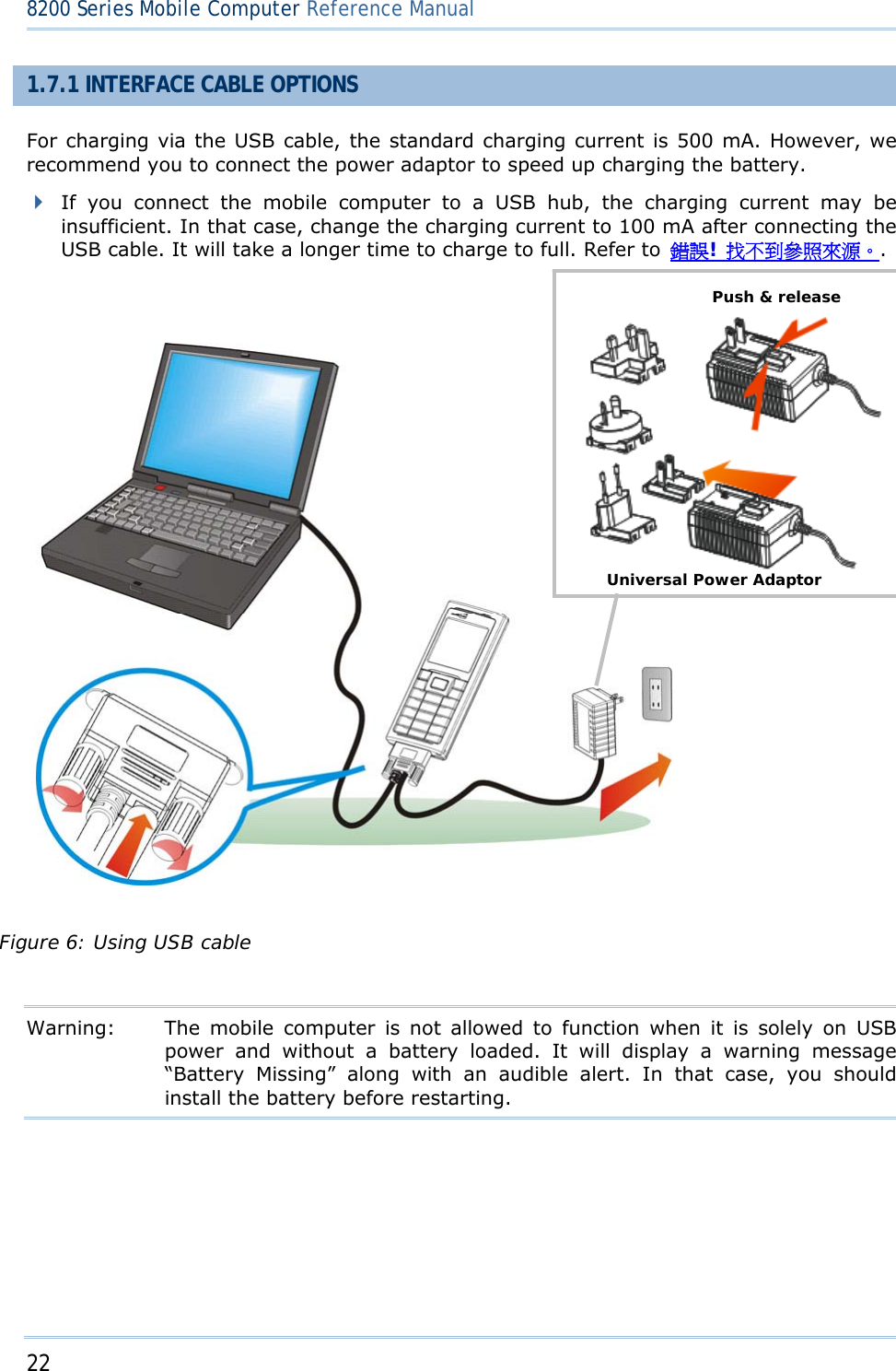
![21 Chapter 1 錯誤! 使用 [常用] 索引標籤將 Heading 1 套用到您想要在此處顯示的文字。1.7 CHARGING & COMMUNICATIONS Normally, the mobile computer ships with a USB cable for charging and communications. USB Interface Cable Task USB Cable Charging USB direct charging 500 mA: USB icon 100 mA: Highlighted USB icon 0 mA: Disable charging for 8200 5 V charging from the adaptor (Plug icon) Communications USB Virtual COM — If using FORGE Application Generator software, you may use a download utility to receive data on your computer; otherwise, run HyperTerminal.exe to receive data directly. USB HID — Run a text editor on your computer to receive data directly. USB Virtual COM_CDC — If using FORGE Application Generator software, you may use a download utility to receive data on your computer; otherwise, run HyperTerminal.exe to receive data directly. Note: (1) If you are using USB Virtual COM for the first time, you must install its driver from the CD-ROM. Driver version 5.3 or later is required. Please remove older versions! The virtual COM port will not be assigned until the USB port is in use. (2) If you are using USB Virtual COM_CDC for the first time, you must install its driver from the CD-ROM. USB CDC driver installer is available in the “Windows” folder, which will copy a vendor-supplied INF file to Windows. (3) For Standard USB cable, it will release COM port in the following conditions: (i) detach the cable from the mobile computer directly。](https://usermanual.wiki/CipherLab/8260/User-Guide-1487786-Page-29.png)
![23 Chapter 1 錯誤! 使用 [常用] 索引標籤將 Heading 1 套用到您想要在此處顯示的文字。 1.8 SD CARD SD card can be accessed directly by using the provided functions in user application. Yet, when 8200 is equipped with SD card and connected to your computer via the USB cable, it can be treated as a removable disk (USB mass storage device) as long as it is configured properly through programming or via System Menu | 8. Next Page | 1. SD Card Menu | 1. Run As USB Disk. Refer to 錯誤! 找不到參照來源。. Note: (1) DAT files created on SD card by previous BASIC runtime are not compatible in file format with new BASIC runtime, starting from version 1.10. (2) While running BASIC application, the size of DAT files on SD card can be calibrated. Go to System Menu | 8. Next Page | 1. SD Card Menu | 2. Access SD Card | 4. Check File Size to refresh the size of “A:\BASICRUN\TXACTn.DAT” (n=1~6). 1.8.1 FILE SYSTEM For 8200 Series, it supports FAT12/FAT16/FAT32 and allows formatting the card through C programming or via System Menu | 8. Next Page | 1. SD Card Menu | 2. Access SD Card. Based on the capacity of the card, it will automatically decide the FAT format: Card Capacity FAT Format Sectors per Cluster ≦ 32 MB FAT12 32 ≦ 1 GB FAT16 32 ≦ 2 GB FAT16 64 ≦ 8 GB FAT32 8 1.8.2 DIRECTORY Unlike the file system on SRAM, the file system on SD card supports hierarchical tree directory structure and allows creating sub-directories. Several directories are reserved for particular use. Reserved Directory Related Application or Function Remark \Program System Menu | Load Program Program Manager | Download Program Manager | Activate Kernel Menu | Kernel Update UPDATE_BASIC() Store programs to this folder so that you can download them to 8200: C program — *.SHX BASIC program — *.INI and *.SYN](https://usermanual.wiki/CipherLab/8260/User-Guide-1487786-Page-31.png)
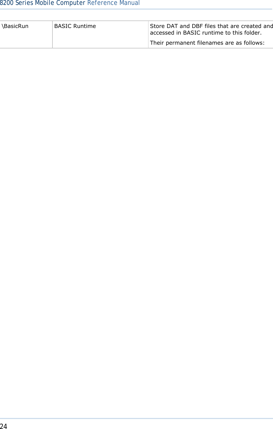
![25 Chapter 1 錯誤! 使用 [常用] 索引標籤將 Heading 1 套用到您想要在此處顯示的文字。 DAT Filename DAT file #1 TXACT1.DAT DAT file #2 TXACT2.DAT DAT file #3 TXACT3.DAT DAT file #4 TXACT4.DAT DAT file #5 TXACT5.DAT DAT file #6 TXACT6.DAT DBF Filename DBF file #1 Record file F1.DB0 System Default Index F1.DB1 Index file #1 F1.DB2 Index file #2 F1.DB3 Index file #3 F1.DB4 DBF file #2 Record file F2.DB0 System Default Index F2.DB1 Index file #1 F2.DB2 Index file #2 F2.DB3 Index file #3 F2.DB4 DBF file #3 Record file F3.DB0 System Default Index F3.DB1 Index file #1 F3.DB2 Index file #2 F3.DB3 Index file #3 F3.DB4 DBF file #4 Record file F4.DB0 System Default Index F4.DB1 Index file #1 F4.DB2 Index file #2 F4.DB3 Index file #3 F4.DB4 DBF file #5 Record file F5.DB0 System Default Index F5.DB1 Index file #1 F5.DB2 Index file #2 F5.DB3 Index file #3 F5.DB4](https://usermanual.wiki/CipherLab/8260/User-Guide-1487786-Page-33.png)
![26 8200 Series Mobile Computer Reference Manual \AG\DBF \AG\DAT \AG\EXPORT \AG\IMPORT Application Generator (a.k.a. AG) Store DAT, DBF, and Lookup files that are created and/or accessed in Application Generator to this folder. 1.8.3 FILE NAME A file name must follow 8.3 format (= short filenames) — at most 8 characters for filename, and at most three characters for filename extension. The following characters are unacceptable: “ * + , : ; < = > ? | [ ] On 8200 Series, it can only display a filename of 1 ~ 8 characters (the null character not included), and filename extension will be displayed if provided. If a file name specified is longer than eight characters, it will be truncated to eight characters. Long filenames, at most 255 characters, are allowed when using 8200 equipped with SD card as a mass storage device. For example, you may have a filename “123456789.txt” created from your computer. However, when the same file is directly accessed on 8200, the filename will be truncated to “123456~1.txt”. If a file name is specified other in ASCII characters, in order for 8200 to display it correctly, you may need to download a matching font file to 8200 first. The file name is not case-sensitive.](https://usermanual.wiki/CipherLab/8260/User-Guide-1487786-Page-34.png)
![27 This chapter mainly describes the software inside the mobile computer. It consists of three modules — Kernel, System, and Application; each has a function menu. When a menu is displayed, you may select an item by either of the following ways: Press the arrow keys [Up] and [Down] to move the highlight bar. Press the number key that corresponds to the item number. Follow the on-screen instructions to change a specific setting, or press [ESC] to return to a previous page or menu. On each screen, the bottom line displays status icons, such as: The 4-bar battery icon indicates the current power status. The status icon of input mode or function mode is controlled by the [Fn α] key. Chapter 2 LEARNING SOFTWARE ARCHITECTURE](https://usermanual.wiki/CipherLab/8260/User-Guide-1487786-Page-35.png)
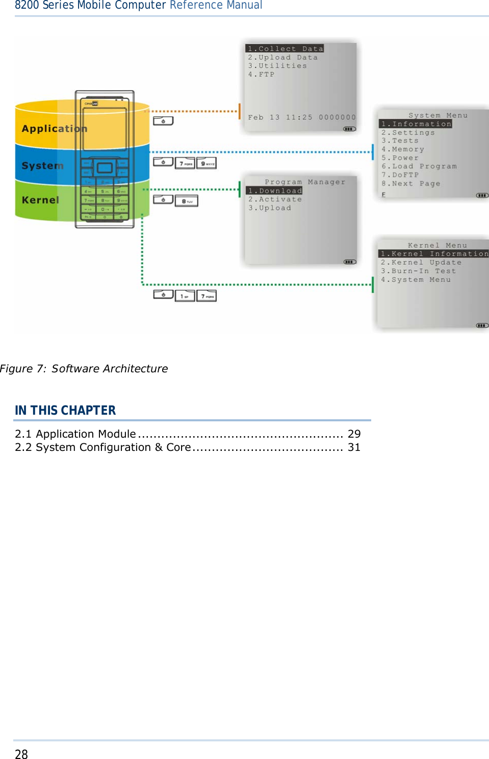
![29 Chapter 2 錯誤! 使用 [常用] 索引標籤將 Heading 1 套用到您想要在此處顯示的文字。2.1 APPLICATION MODULE The mobile computer ships with software package on the CD-ROM. It includes FORGE Application Generator (batch and WLAN versions), MIRROR Emulator (VT and 5250 versions), download utilities, etc. 2.1.1 FORGE APPLICATION GENERATOR (AG) For easy development of applications, the mobile computer is preloaded with AG runtime. When you turn on the mobile computer, it displays the Main Menu of AG application, as shown below. Batch AG WLAN AG Note: Batch AG supports automatically uploading data to a host computer when the upload interface is properly configured. Once the mobile computer is connected via the USB Virtual COM cable, there will be a moving hourglass icon displayed on the upper-right corner of the screen, indicating the mobile computer is ready for auto upload. Before using the mobile computer to collect data, you need to configure the application with the companion tool on your computer. This time-saving development tool helps create application templates on your computer. For details on the AG application, please refer to separate user manual. Application Generator AG Runtime Companion Tool on PC End Batch AG U8200.SHX ForgeAG.exe WLAN AG WU8200.SHX AG8200WLAN.exe Note: FORGE Application Generator (AG) software package includes (1) a companion tool for quickly developing your application — Batch or WLAN AG; (2) several download utilities to make it versatile in use.](https://usermanual.wiki/CipherLab/8260/User-Guide-1487786-Page-37.png)
![31 Chapter 2 錯誤! 使用 [常用] 索引標籤將 Heading 1 套用到您想要在此處顯示的文字。2.2 SYSTEM CONFIGURATION & CORE For managing system configurations and multiple programs, each mobile computer comes with System Menu, Program Manager, and Kernel Menu. Refer to the following chapters on how to configure the 8200 Series Mobile Computer, regarding system configurations and program download. 2.2.1 SYSTEM MENU System Menu is bundled with BASIC Runtime or user programs that are written in “C”. It is provided for system configuration, functionality testing, downloading font file and program. 2.2.2 KERNEL Kernel is the innermost core of the OS. It provides services for updating the kernel and bootloader, and repairing the system. 2.2.3 PROGRAM MANAGER Program Manager is part of the kernel. You may download as many as seven application programs.](https://usermanual.wiki/CipherLab/8260/User-Guide-1487786-Page-39.png)