CipherLab 8260 Terminal User Manual manual
CipherLab Co., Ltd. Terminal manual
manual
T
erminal
8200/8230/8260
Version 1.00

Copyright © 2009~2011 CIPHERLAB CO., LTD.
All rights reserved
The software contains proprietary information of CIPHERLAB CO., LTD.; it is provided
under a license agreement containing restrictions on use and disclosure and is also
protected by copyright law. Reverse engineering of the software is prohibited.
Due to continued product development this information may change without notice. The
information and intellectual property contained herein is confidential between CIPHERLAB
and the client and remains the exclusive property of CIPHERLAB CO., LTD. If you find
any problems in the documentation, please report them to us in writing. CIPHERLAB
does not warrant that this document is error-free.
No part of this publication may be reproduced, stored in a retrieval system, or
transmitted in any form or by any means, electronic, mechanical, photocopying,
recording or otherwise without the prior written permission of CIPHERLAB CO., LTD.
For product consultancy and technical support, please contact your local sales
representative. Also, you may visit our web site for more information.
The CipherLab logo is a registered trademark of CIPHERLAB CO., LTD.
All brand, product and service, and trademark names are the property of their registered
owners.
The editorial use of these names is for identification as well as to the benefit of the
owners, with no intention of infringement.
CIPHERLAB CO., LTD.
Website: http://www.cipherlab.com
IMPORTANT NOTICES

FOR USA
This equipment has been tested and found to comply with the limits for a Class B digital
device, pursuant to Part 15 of the FCC Rules. These limits are designed to provide
reasonable protection against harmful interference in a residential installation. This
equipment generates, uses and can radiate radio frequency energy and, if not installed
and used in accordance with the instructions, may cause harmful interference to radio
communications. However, there is no guarantee that interference will not occur in a
particular installation. If this equipment does cause harmful interference to radio or
television reception, which can be determined by turning the equipment off and on, the
user is encouraged to try to correct the interference by one or more of the following
measures:
Reorient or relocate the receiving antenna.
Increase the separation between the equipment and receiver.
Connect the equipment into an outlet on a circuit different from that to which the
receiver is connected.
Consult the dealer or an experienced radio/TV technician for help.
This device complies with Part 15 of the FCC Rules. Operation is subject to the following
two conditions: (1) This device may not cause harmful interference, and (2) this device
must accept any interference received, including interference that may cause undesired
operation.
FOR CANADA
This digital apparatus does not exceed the Class B limits for radio noise emissions from
digital apparatus as set out in the interference-causing equipment standard entitled
"Digital Apparatus," ICES-003 of Industry Canada.
This device complies with Part 15 of the FCC Rules. Operation is subject to the following
two conditions: (1) This device may not cause harmful interference, and (2) this device
must accept any interference received, including interference that may cause undesired
operation.
Cet appareil numerique respecte les limites de bruits radioelectriques applicables aux
appareils numeriques de Classe B prescrites dans la norme sur le material brouilleur:
"Appareils Numeriques," NMB-003 edictee par l'Industrie.
FOR HAND-HELD PRODUCT WITH RF FUNCTIONS
This equipment complies with FCC radiation exposure limits set forth for an uncontrolled
environment. This equipment should be installed and operated with minimum distance 20
cm between the radiator & your body. It only operated in hand-held used.

If you only transfer data to the host wirelessly, please keep the minimum distance 20 cm
between machine & your body.
FOR PRODUCT WITH LASER
CAUTION
This laser component emits FDA / IEC Class 2 laser light at the exit port. Do not
stare into beam.
SAFETY PRECAUTIONS
RISK OF EXPLOSION IF BATTERY IS REPLACED BY AN INCORRECT TYPE.
DISPOSE OF USED BATTERIES ACCORDING TO THE INSTRUCTIONS.
The use of any batteries or charging devices, which are not originally sold or
manufactured by CipherLab, will void your warranty and may cause damage to
human body or the product itself.
DO NOT disassemble, incinerate or short circuit the battery.
DO NOT expose the scanner or the battery to any flammable sources.
For green-environment issue, it's important that batteries should be recycled in a
proper way.
Under no circumstances, internal components are self-serviceable.
CARE & MAINTENANCE
This mobile computer is intended for enterprise logistics use. The mobile computer is
rated IP 52, however, it may do damage to the mobile computer when being exposed
to extreme temperatures or soaked wet.
When the body of the mobile computer gets dirty, use a clean and wet cloth to wipe
off the dust. DO NOT use/mix any bleach or cleaner. Always keep the LCD dry.
For a liquid crystal display (LCD), use a clean, non-abrasive, lint-free cloth to wipe
dust off the screen. DO NOT use any pointed or sharp object to move against the
surface.
If you want to put away the mobile computer for a period of time, download the
collected data to a host computer, and then take out the battery pack. Store the
mobile computer and battery pack separately.
When the mobile computer resumes its work, the main and backup batteries will take
a certain time to become fully charged.
If you shall find the mobile computer malfunctioning, write down the specific scenario
and consult your local sales representative.
Version Date Notes
RELEASE NOTES
1.00 Mar. 21, 2011 Initial release

CONTENTS
IMPORTANT NOTICES ................................................................................ - 2 -
For USA .............................................................................................. - 3 -
For Canada .......................................................................................... - 3 -
For Hand-held Product with RF Functions ..................................................... - 3 -
For Product with Laser ........................................................................... - 4 -
Safety Precautions................................................................................. - 4 -
Care & Maintenance ............................................................................... - 4 -
RELEASE NOTES ....................................................................................... - 4 -
INTRODUCTION ........................................................................................... 1
Getting Familiarized with 8200
Features
Inside the Package
Accessories
Getting Started
Inserting Battery & Memory Card
Installing Pistol Grip
Initial Charging
Setting Local Time
Power Management
USING 8200 MOBILE COMPUTER ...................................................................... 9
1.1 Battery
1.1.1 Main Battery
1.1.2 Backup Battery
1.1.3 Caution of Low Battery Charge
1.2 Memory
1.2.1 Read-only Memory (ROM)
1.2.2 Random-access Memory (RAM)
1.2.3 SD Card
1.3 Keypad
1.3.1 24-key Layout
1.4 LCD
1.4.1 Adjusting the Backlight
1.5 Notifications
1.5.1 Status LED
1.5.2 Audio
1.5.3 Vibrator
1.6 Data Capture
1.7 Charging & Communications
1.7.1 Interface Cable Options

8200 Series Mobile Compute
r
Reference Manual
1.8 SD Card
1.8.1 File System
1.8.2 Directory
1.8.3 File Name
LEARNING SOFTWARE ARCHITECTURE ............................................................. 27
2.1 Application Module
2.1.1 FORGE Application Generator (AG)
2.1.2 MIRROR Emulator (CipherNet)
2.1.3 User Program
2.2 System Configuration & Core
2.2.1 System Menu
2.2.2 Kernel
2.2.3 Program Manager
SPECIFICATIONS ......................................................................................... 32

1
Answering industrial demands for ruggedized, light-weight and versatile computers, the
8200 Series Mobile Computer is specifically designed for enterprise logistics use.
This line of product comes with built-in Bluetooth technology and allows for optional
module for 802.11b/g connectivity, enabling real time sharing of performance.
The 8200 Series Mobile Computer is bundled with powerful and rich features to ensure
success in timely processing of information, and thus, makes an ideal choice for
inventory control, shop floor management, warehousing and distribution operations.
Being programmable, this handy device can run custom applications or terminal
emulation applications.
This manual serves to guide you through how to install, configure, and operate the
mobile computer. We recommend you to keep one copy of the manual at hand for quick
reference or maintenance purposes. To avoid any improper disposal or operation, please
read the manual thoroughly before use.
Thank you for choosing CipherLab products!
INTRODUCTION
2
8200 Series Mobile Compute
r
Reference Manual
GETTING FAMILIARIZED WITH 8200
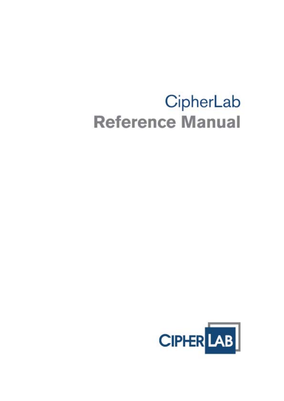
No. Description No.
Description
1 Scanning window 2 LED for Good Read and battery charging
3 LED for wireless communications 4 LCD screen
5 Keypad, 24 keys 6 Wristband
7 Communication/charging port 8 Battery compartment
Figure 1: Overview

3
錯誤! 使用 [常用] 索引標籤將
Heading 1 套用到您想要在此處顯示的文字。
FEATURES
Ergonomic design — ruggedized yet streamlined, with wristband for secure hold
Built tough to survive drop test and sealed against moisture/dust to IP 52
Up to 8 GB high capacity memory card (microSDHC) supported
Flexible wireless solutions — Bluetooth or 802.11b/g
FTP client support — 802.11b/g
Graphic monochrome LCD supports double-byte characters and bitmap graphics
Programmable feedback includes speaker, LED indicators and vibrator
Quick link to any backend database through MIRROR Emulator programs for
VT100/220 and IBM 5250 emulation
Easy customization of data collection applications through FORGE Application
Generator (AG) programs for preloaded AG Runtime, batch and WLAN versions
available
Programming support includes BASIC & C compilers
Accessories include pistol grip.
INSIDE THE PACKAGE
The following items are included in the package. Save the box and packaging material for
future use in case you need to store or ship the mobile computer.
8200 Series mobile computer
Rechargeable Li-ion battery pack
Wristband
Standard USB cable
Universal power adaptor
Product CD
Quick Start Guide

4
8200 Series Mobile Compute
r
Reference Manual
ACCESSORIES
Rich choices of optional accessories are available for you to enhance the total
performance of the mobile computer.
Pistol Grip (detachable)
Spare rechargeable Li-ion battery
GETTING STARTED
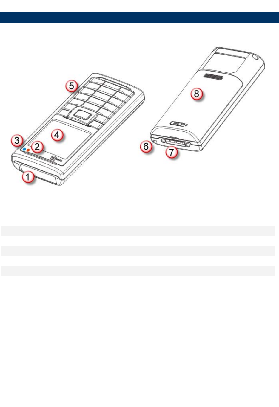
INSERTING BATTERY & MEMORY CARD
For shipping and storage purposes, save the mobile computer and the main battery in
separate packages. This will keep both batteries in good condition for future use.
Note: Any improper handling may reduce the battery life.
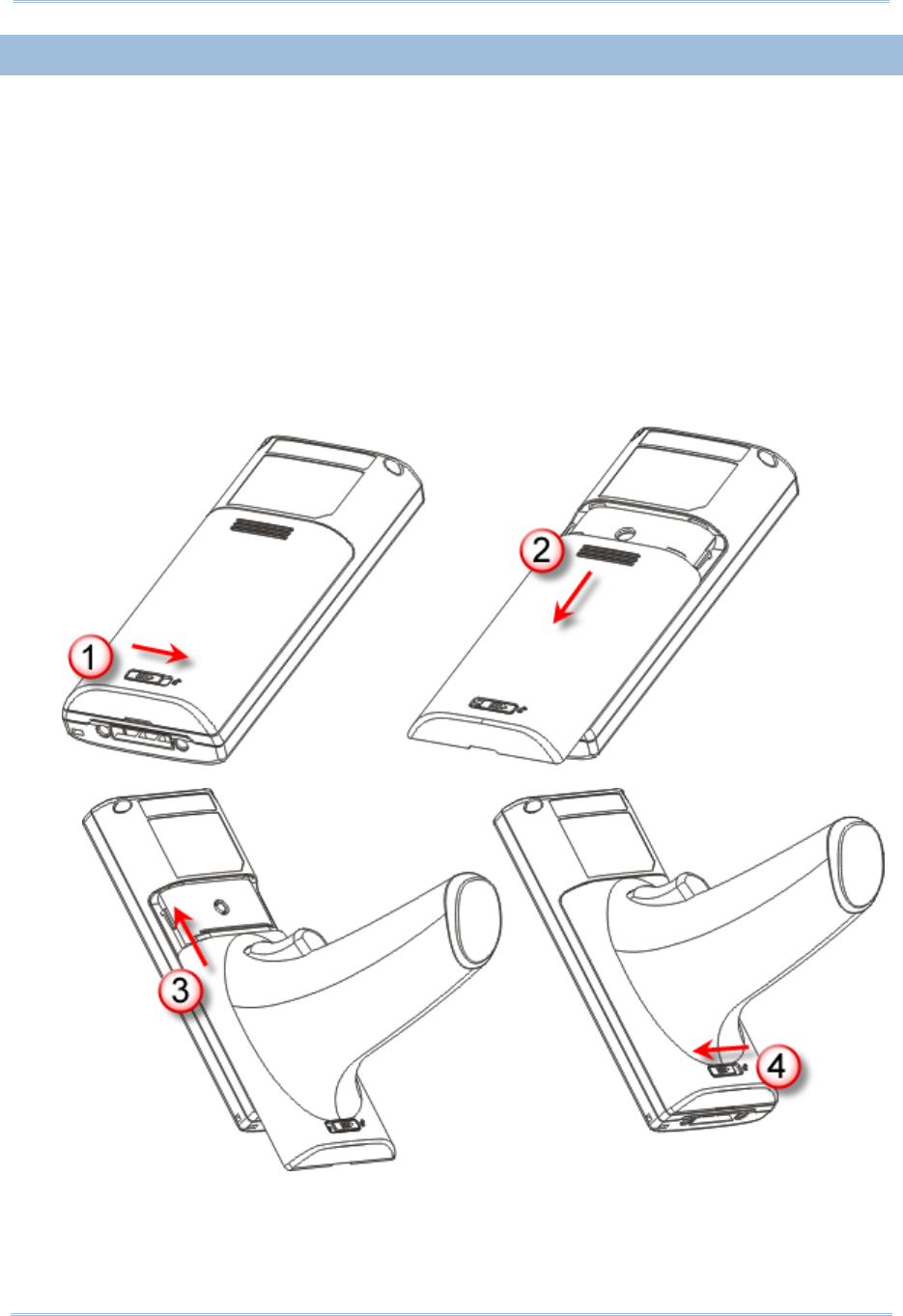
1) Hold the mobile computer still and slide the release latch to the right to unlock the
battery cover.
2) Slide off the battery cover.
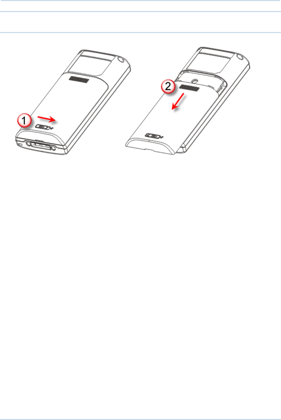
3) Use your finger to slide the locking plate towards its hinge to unlock the SD card
holder.
4) Flip up the SD card holder.
5) Insert your memory card (microSD or microSDHC) to the SD card holder.
6) Push the SD card holder down.
7) Slide the locking plate away from its hinge to secure the card.
8) Slide the battery pack into the battery compartment at a proper angle (30°~45°) so
that the metal contacts of the battery are met with the charging contacts inside the
compartment. Make sure that the battery is snugly fit into the compartment.
9) Replace the battery cover.
10) Slide the release latch to the left to lock it firmly.
5
錯誤! 使用 [常用] 索引標籤將
Heading 1 套用到您想要在此處顯示的文字。
Note: For a new battery, make sure it is fully charged before use. Always prepare a
spare battery pack, especially when you are on the road.
6
8200 Series Mobile Compute
r
Reference Manual
Figure 2: Installing the Main Battery & Memory Card
Unlock
Lock
7
錯誤! 使用 [常用] 索引標籤將
Heading 1 套用到您想要在此處顯示的文字。
INSTALLING PISTOL GRIP
This contoured pistol grip enables intuitive trigger-and-scan operation, which is very
helpful in scan intensive applications.
When a pistol grip is necessary, install it to the mobile computer by following these
steps:
1) Hold the mobile computer still and slide the release latch to the right to unlock the
battery cover.
2) Slide off the battery cover.
3) Insert the pistol grip into place (is like replacing the battery cover).
4) Slide the release latch to the left to lock it firmly, and turn on the mobile computer to
test the trigger.
Figure 3: Installing the Pistol Grip

8
8200 Series Mobile Compute
r
Reference Manual
INITIAL CHARGING
The main and backup batteries may not be charged to full for shipment. When you first
receive the package, you will need to charge the main battery to full before using the
mobile computer.
Note: Battery charging stops when the temperature drops below 0°C or exceeds 40°C. It
is recommended to charge the battery at room temperature (18°C to 25°C) for
optimal performance. For initial charging, it takes approximately 2.5 hours to
charge the battery to full (from the adaptor).
Because the internal backup battery is constantly charged from the main battery, the
initial charging requires inserting the battery pack to the mobile computer for charging.
This will have both the main and backup batteries charged at the same time. It takes at
least 72 hours to fully charge the backup battery. However, it is not necessary to fully
charge the backup battery for the mobile computer to work.
Note: In order to charge the backup battery to full, you must insert the main battery and
leave it for at least 72 hours, whether the mobile computer is in use or not.
SETTING LOCAL TIME
If you need to set your local time, go to System Menu | 2. Settings | 1. Clock. Refer
to 錯誤! 找不到參照來源。.
POWER MANAGEMENT
For any portable device, power management is a critical issue especially when you are on
the road. Below are some tips to help you save battery power.
Warning: Using backlight, wireless connectivity, and peripherals while on battery
power will substantially reduce battery power.
To speed up charging the mobile computer, turn off the mobile computer and use the
charging/communication cable.
Bring a second battery pack on the road.
Stop wireless connectivity, Bluetooth or 802.11b/g that is not in use.
Go to System Menu | 2. Settings | 2. Backlight, and configure backlight period,
luminosity, as well as the shade effect. Refer to 錯誤! 找不到參照來源。.
Go to System Menu | 2. Settings | 4. Auto Off, and configure the amount of idle
time that must pass before the system will shut down automatically. Refer to 錯誤! 找
不到參照來源。.

9
This chapter explains the features and usage of the 8200 Series Mobile Computer. The
8200 family includes:
8200 Batch type
8230 Bluetooth Class 2 + 802.11b/g
8260 Bluetooth Class 2
IN THIS CHAPTER
1.1 Battery ....................................................................... 9
1.2 Memory .................................................................... 11
1.3 Keypad ..................................................................... 12
1.4 LCD ......................................................................... 16
1.5 Notifications .............................................................. 17
1.6 Data Capture ............................................................ 19
1.7 Charging & Communications ........................................ 21
1.8 SD Card ................................................................... 23
1.1 BATTERY
1.1.1 MAIN BATTERY
The mobile computer is powered by a rechargeable 3.7 V/1200 mAh Li-ion battery pack.
When the mobile computer is turned on, it takes approx. 2.5 hours to charge it to full
from the power adaptor (using cable) or approx. 4 hours from the USB cable (at 500
mA).
For power-saving purpose, always turn off the backlight while working in a well-lit area.
When the backlight is on for extended periods of time, the main battery will become low
sooner than expected.
The smart battery icon on the LCD screen shows the status of power consumption. There
are two ways to monitor a low battery charge or discharged battery from the screen.
Examine the level of the 4-bar battery icon
Monitor voltage level (see 3.5 Power)
Chapter 1
USING 8200 MOBILE COMPUTER

10
8200 Series Mobile Compute
r
Reference Manual
1.1.2 BACKUP BATTERY
The backup battery on the main board takes charge when the main battery is removed or
drained out. When fully charged, the 3.0 V/18 mAh rechargeable Lithium button cell
helps retain data in SRAM and maintain the running of the real-time clock and calendar
for at least 25 days without the main battery. In the meantime, you have to replace the
main battery as soon as possible. It takes at least 72 hours to fully charge the backup
battery. However, it is not necessary to fully charge the backup battery for the mobile
computer to work.
Monitor voltage level (see 3.5 Power)
1.1.3 CAUTION OF LOW BATTERY CHARGE
The battery pack is the only power source for the mobile computer to work. It also
charges the backup battery on the main board so that the data stored in SRAM can be
retained properly. Therefore, when the main battery charge goes low, you need to
replace the battery pack with a charged one or charge it as soon as possible. Most of all,
you should upload important data on a regular basis.
Warning: Data loss may occur with SRAM during low battery condition. Always save
data before running out of power or keep a fresh battery for replacement.

11
Chapter 1 錯誤! 使用 [常用] 索引標籤將
Heading 1 套用到您想要在此處顯示的文字。
1.2 MEMORY
The collected data can be sent back to a host computer immediately over wireless
networks, or stored in memory (SRAM) and upload later. The mobile computer is
equipped with a calendar chip for accurate time/date logging. When the main battery is
removed or drained, the backup battery on the main board is to retain the contents of
SRAM and maintain the running of real-time clock and calendar for at least 25 days, on
condition that the backup battery has already been fully charged.
If you want to put away the mobile computer for a couple of days, you should be aware
that data loss occurs when both the main and backup batteries discharge completely.
Therefore, it is necessary to upload data and files before putting away the mobile
computer!
1.2.1 READ-ONLY MEMORY (ROM)
8 megabytes flash memory for storing core, OS, application programs, font, etc.
1.2.2 RANDOM-ACCESS MEMORY (RAM)
Options include 4 or 8 megabytes SRAM for storing data. Its contents will be retained by
the backup battery.
1.2.3 SD CARD
Secure Digital (SD) card is a flash memory data storage device. Up to 8 GB high capacity
memory card (microSDHC) is supported. Refer to Inserting Battery & Memory Card for
how to insert the microSD or microSDHC card. For more details, refer to 1.8 SD Card.
Note: (1) When SD card is present, the card icon will appear on the screen and flash
while being accessed.
(2) For an SD card that has never been used on 8200, a message like “Found New
SD Card” will be displayed allowing users to scan the card for memory check. If
the action is canceled then, memory check can still be performed via System
Menu — 錯誤! 找不到參照來源。.
12
8200 Series Mobile Compute
r
Reference Manual
1.3 KEYPAD
The mobile computer is equipped with a keypad of 24 keys for system setup, user entry
and so on. The keypad comes with programmable LED backlight, like the screen. Refer to
1.4 LCD for screen & backlight settings.
Silicon rubber has been chosen for their durability and prompt feedback. The key click
can be configured through programming or via System Menu. Refer to 錯誤! 找不到參照
來源。.
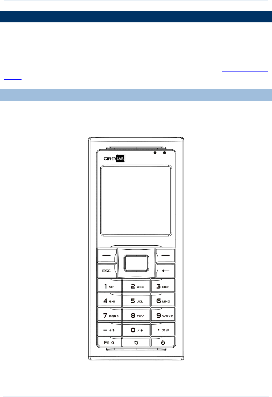
1.3.1 24-KEY LAYOUT
The layout of the 24-key keypad is similar to that of a telephone, which includes
alphanumeric, navigation and function keys, as well as assorted characters. Refer to
Appendix III — 錯誤! 找不到參照來源。 for color-coded keys.
Figure 4: 24-key Layout
13
Chapter 1 錯誤! 使用 [常用] 索引標籤將
Heading 1 套用到您想要在此處顯示的文字。
This alphanumeric keypad is set to numeric mode by default. The [Fn α] key serves as a
toggle among numeric, alpha (lower-case alphabetic), and ALPHA (upper-case alphabetic)
input modes, as well as function mode.
Note: It is not necessary to hold down the [Fn α] key.
The associated icon will appear on the lower-left corner of the screen in a sequence as
shown below.
Status Icon Function/Alpha Key Input Mode
(none) N/A Numbers
A Press [Fn α] one time Upper-case alphabetic
a Press [Fn α] two times Lower-case alphabetic
F Press [Fn α] three times Function Mode
When in alpha mode, it takes turns to show alphabets and number when you keep
pressing the same key; each press must not exceed one second. For example, keep
pressing the number key [2], it will take turns to show “A”, “B”, “C” or “2” for upper-case,
and “a”, “b”, “c” or “2” for lower-case.
When you first press the number key [2], it will produce the letter “A” or “a”.
When you press the number key [2] twice (the time interval must not exceed one
second), it will produce the letter “B” or “b”.
When you press the number key [2] three times (the time interval between each
press must not exceed one second), it will produce the letter “C” or “c”.
When you press the number key [2] four times (the time interval between each press
must not exceed one second), it will produce the number “2”.
In order to get the desired character, you will need to press the same key, one to four
times (the time interval between each press must not exceed one second). Only when
you stop pressing the same key for longer than one second or you press another key, will
the system send the real key code to the application program.
When in function mode, the [Fn α] key works with a number key. Press the [Fn α] key
three times, and its associated icon F will be displayed on the screen. Press the second
key, say [5], to complete the key combination and access the function [F5]. Press [Fn α]
again and the icon F will go off.
14
8200 Series Mobile Compute
r
Reference Manual
Below briefly describes the functions of common keys on the mobile computer.
SCAN
The yellow key is used to work as the ENTER key by default.
When the reader function is enabled, this yellow key is set to trigger the scan engine so that it
can read a barcode.
ENTER
The two keys on each upper side of the SCAN key are user-friendly and convenient for either
right-handed or left-handed operator. Normally, it is used for command execution or input
confirmation.
ESC (Escape)
This key is on the left lower side of the SCAN key. Normally, it is used to stop and exit the current
operation.
Navigation Pad
The 4-way navigation pad around the SCAN key is used to move the cursor left, up, down, or
right.
While pressing [ ], they can be used to adjust the luminosity and contrast of the screen
backlight.
Backspace
This key is Backspace by default. If this key is being held down for more than one second, a
clear code will be sent.
Function/Alpha Key
This key is a modifier key that requires pressing a second key to get the yellow-coded letter (A~Z)
or symbol printed above the second key, or the function (F0~F9) of the second key.
Icon Description
A This icon appears when you press the [Fn α] key one time, indicating it is set to
alphabetic mode for typing upper-case alphabetic letters.
a This icon appears when you press the [Fn α] key two times, indicating it is set to
alphabetic mode for typing lower-case alphabetic letters.
F This icon appears when you press the [Fn α] key three times, indicating it is set to the
function mode. Then, press another key ([0] ~ [9]) to get the desired function.
To get the value of another key combination modified by the function key, keep
pressing another key ([0] ~ [9]) to produce the result.
To exit the function mode, press [Fn α] again and the icon will go off.
15
Chapter 1 錯誤! 使用 [常用] 索引標籤將
Heading 1 套用到您想要在此處顯示的文字。
Backlight Configuration Key
This key is used to turn ON/OFF the backlight of the LCD and keypad. Also, while pressing [ ],
the navigation keys can be used to adjust the luminosity and contrast of the screen backlight.
Key Description
[] + [Right] Press these keys at the same time to increase the contrast.
[] + [Left] Press these keys at the same time to decrease the contrast.
[] + [Up] Press these keys at the same time to increase the luminosity.
[] + [Down] Press these keys at the same time to decrease the luminosity.
Power Key
In order to prevent an accidental press of the POWER key, you need to hold down this key for
approximately 1.5 seconds to turn ON/OFF the mobile computer.
Note: (1) Functionality of keys is application-dependent. The system will send the
associated key code to the application program, and it is up to the application
program to interpret the key code.
(2) When a status icon appears on the screen, it indicates a certain mode is
activated and it is not necessary to hold down the modifier key.
16
8200 Series Mobile Compute
r
Reference Manual
1.4 LCD
The mobile computer comes with a FSTN graphic LCD, 160 by 160 pixels resolutions,
which can be programmed to display text or graphics, such as specific font and company
logo, to meet varying application needs.
Options Font Size (pixels) Characters by lines
English font Font size 6×8 (pixels)
Font size 8×16 (pixels)
26 characters by 18 lines
20 characters by 9 lines
Chinese font Font size 12×12 (pixels)
Font size 16×16 (pixels)
13 characters by 12 lines
10 characters by 9 lines
Other language fonts, company logo… Programmable
Note: The bottom line (ICON_ZONE) is reserved to display status icons, such as the
battery icon.
1.4.1 ADJUSTING THE BACKLIGHT
The backlight of screen and keypad helps ease reading under dim environments. It can
be turned on and adjusted decreasingly or increasingly by the following key combinations.
Keep pressing the key combination until the luminosity or contrast is decreased or
increased to a desired level. Alternatively, the luminosity and contrast can be configured
through programming or via System Menu. Refer to 錯誤! 找不到參照來源。 and 錯誤! 找
不到參照來源。.
Note: Using backlight while on battery power will substantially reduce battery power. We
suggest that you dim the backlight while working in a well-lit area or have it set to
be automatically turned off when not in use.
Key Combination Action
[] Toggle ON/OFF the backlight
[] + [Up] Turn ON the backlight and increase the luminosity of LCD
[] + [Down] Turn ON the backlight and decrease the luminosity of LCD
[] + [Right] Turn ON the backlight and increase the contrast of LCD
[] + [Left] Turn ON the backlight and decrease the contrast of LCD
Note: Hold down the first key, and keep pressing the second key for adjustment.
17
Chapter 1 錯誤! 使用 [常用] 索引標籤將
Heading 1 套用到您想要在此處顯示的文字。
1.5 NOTIFICATIONS
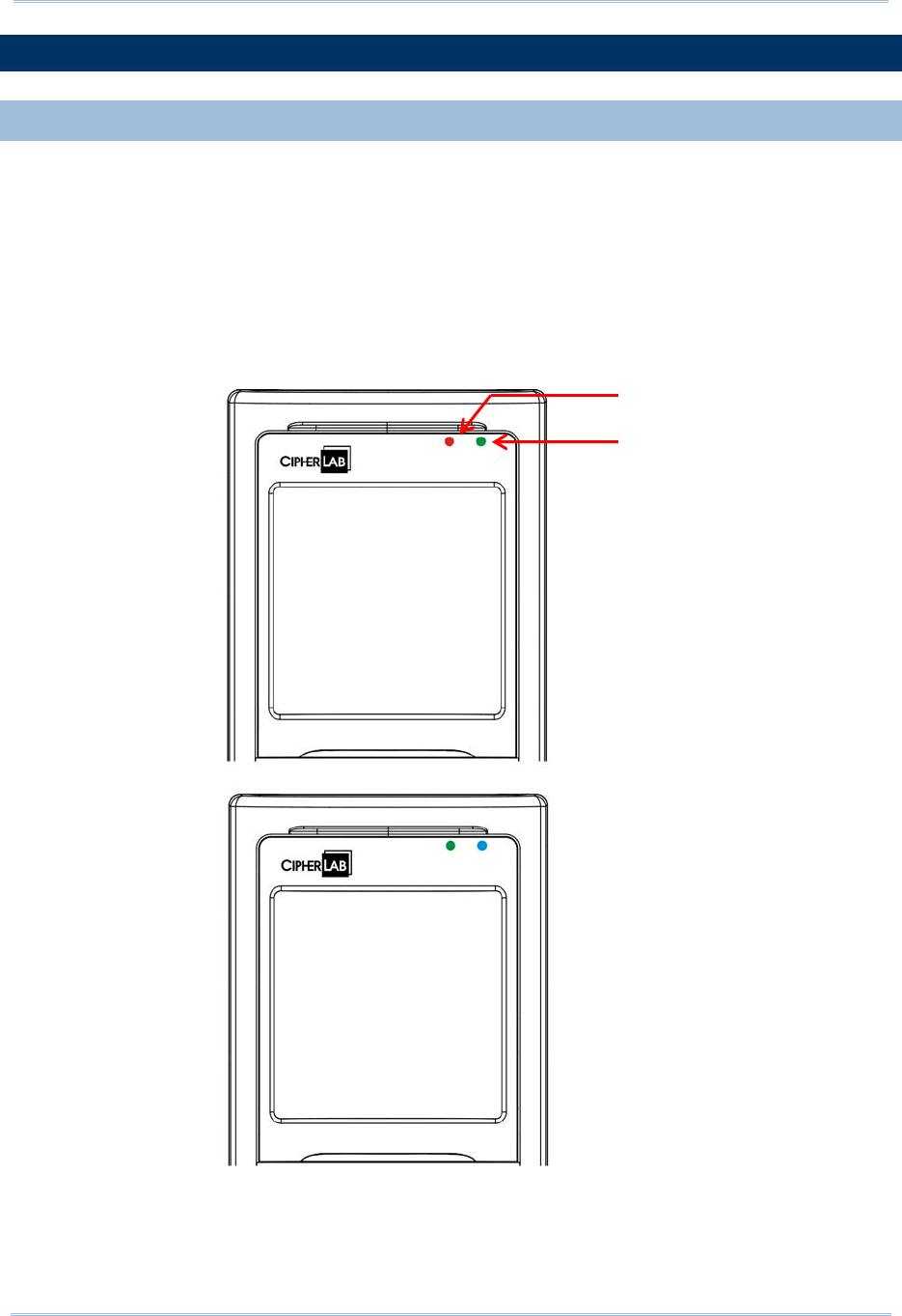
1.5.1 STATUS LED
There are two dual-color LED indicators above the screen. Both can be programmed to
provide information that helps diagnosing. For example, if you are using AG runtime, you
will be informed of the scanning result immediately. LED1 is used for "Good Read" and
will become solid green upon reading a barcode successfully.
LED1 is used to provide information on the charging status and barcode decoding.
LED2 is used to provide information on wireless communications.
Figure 5: LED Indicators
LED1
LED2

18
8200 Series Mobile Compute
r
Reference Manual
LED1: Red/Green Red Green
User Power ON User definable User definable
Solid green for Good Read by
default
Power Off, Battery
Charging
System default
Flashing red: Charging
System default
Flashing green: Charging done
Charging Error System default
Flashing red and green: Charging error occurs
LED2: Blue/Green Blue Green
Bluetooth System default
Flashing blue, quickly: Waiting for
connection or connecting
Flashing blue, slowly: Connected
---
Wi-Fi --- System default
Flashing green, quickly: Waiting
for connection or connecting
Flashing green, slowly:
Connected
1.5.2 AUDIO
The mobile computer has a mono or stereo speaker at the bottom, which can be
programmed for status feedback. It is used to play sounds for events in the programs, or
play audio files such as .WAV files. Its volume can be configured through programming or
via System Menu. Refer to 錯誤! 找不到參照來源。. In particular, its frequency and
duration are software programmable for Good Read in the provided terminal emulation
programs. In noisy environments, you may consider connecting to a Bluetooth headset
instead.
1.5.3 VIBRATOR
The mobile computer is integrated with a vibrator, which can be programmed for status
feedback. It can be helpful when working in noisy environments. In particular, the
vibrator is software programmable for Good Read in the provided terminal emulation
programs.
19
Chapter 1 錯誤! 使用 [常用] 索引標籤將
Heading 1 套用到您想要在此處顯示的文字。
1.6 DATA CAPTURE
A wide variety of scan engines is available for delivering flexibility to meet different
requirements. Depending on the scan engine integrated, the mobile computer is capable
of scanning barcodes of a number of symbologies that are enabled by default while
running the preloaded AG runtime. Refer to 3.3.1 Reader for functional test.
If you need to scan barcodes that are encoded in a symbology, which is disabled by
default in AG runtime, FORGE Application Generator (ForgeAG.exe) allows configuring
symbology settings, as well as reader settings. First, enable the desired symbologies, and
then, download the application settings to the mobile computer.
Note: For details on configuring reader and symbology settings, please refer to the
documentation of the software you use.
Varying by the scan engine installed, the supported symbologies are listed below.
1D CCD scan engine
1D Laser scan engine
2D scan engine
Note: In AG or CipherNet runtime, not all of the symbologies are enabled by default.
Instead of running any of them, you can develop your own applications to control
the scan engine for data collection.
Symbologies Supported (Default Setting: Enable/Disable) CCD/Laser 2D
Codabar Enabled Enabled
Code 11 Enabled
Code 93 Enabled Enabled
Composite
Code CC-A/B Disabled
CC-C Disabled
TCIF Linked Code 39 Enabled
MSI Disabled Enabled
Plessey Disabled
Postal Codes Enabled
Telepen Disabled
Code 128 Code 128 Enabled Enabled
GS1-128 (EAN-128) Enabled Enabled
ISBT 128 Enabled Enabled
Code 2 of 5 Industrial 25 (Discrete 25) Enabled Enabled
Interleaved 25 Enabled Enabled
Matrix 25 Disabled Disabled

20
8200 Series Mobile Compute
r
Reference Manual
Chinese 25 Disabled
Coop 25 Disabled
Code 3 of 9 Code 39 Enabled Enabled
Trioptic Code 39 Disabled
Italian Pharmacode (Code 32) Disabled Disabled
French Pharmacode Disabled
EAN/UPC EAN-8 Enabled Enabled
EAN-8 Addon 2 Disabled Disabled
EAN-8 Addon 5 Disabled Disabled
EAN-13 Enabled Enabled
EAN-13 & UPC-A Addon 2 Disabled Disabled
EAN-13 & UPC-A Addon 5 Disabled Disabled
Bookland EAN (ISBN) Disabled Disabled
UPC-E0 Enabled Enabled
UPC-E1 Disabled Disabled
UPC-E Addon 2 Disabled Disabled
UPC-E Addon 5 Disabled Disabled
UPC-A Enabled Enabled
GS1 DataBar
(RSS)
GS1 DataBar Omnidirectional (RSS-14) Disabled Enabled
GS1 DataBar Truncated Disabled Enabled
GS1 DataBar Stacked Disabled Enabled
GS1 DataBar Stacked Omnidirectional Disabled Enabled
GS1 DataBar Limited (RSS Limited) Disabled Enabled
GS1 DataBar Expanded (RSS Expanded) Disabled Enabled
GS1 DataBar Expanded Stacked Disabled Enabled
2D
Symbologies
PDF417 Enabled
MicroPDF417 Enabled
Data Matrix Enabled
Maxicode Enabled
QR Code Enabled

21
Chapter 1 錯誤! 使用 [常用] 索引標籤將
Heading 1 套用到您想要在此處顯示的文字。
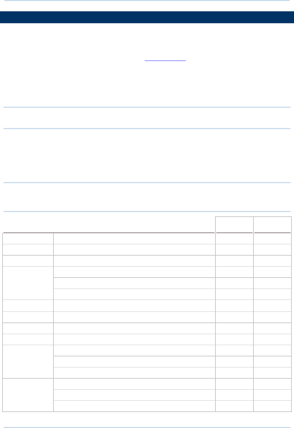
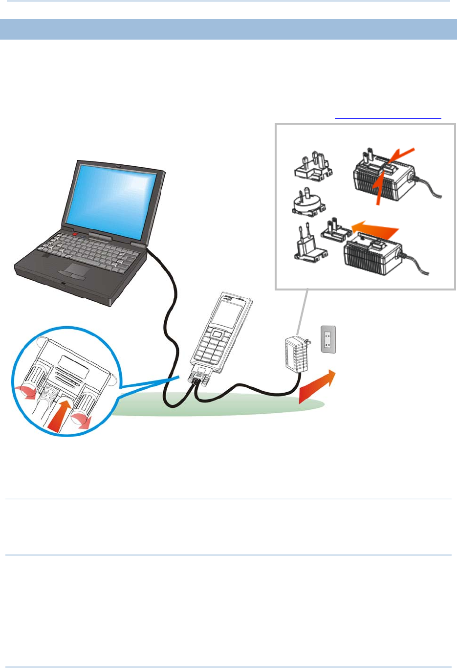
1.7 CHARGING & COMMUNICATIONS
Normally, the mobile computer ships with a USB cable for charging and communications.
USB Interface Cable
Task USB Cable
Charging USB direct charging
500 mA: USB icon
100 mA: Highlighted USB icon
0 mA: Disable charging for 8200
5 V charging from the adaptor (Plug icon)
Communications USB Virtual COM — If using FORGE Application Generator software, you
may use a download utility to receive data on your computer; otherwise,
run HyperTerminal.exe to receive data directly.
USB HID — Run a text editor on your computer to receive data directly.
USB Virtual COM_CDC — If using FORGE Application Generator software,
you may use a download utility to receive data on your computer;
otherwise, run HyperTerminal.exe to receive data directly.
Note: (1) If you are using USB Virtual COM for the first time, you must install its driver
from the CD-ROM. Driver version 5.3 or later is required. Please remove older
versions! The virtual COM port will not be assigned until the USB port is in use.
(2) If you are using USB Virtual COM_CDC for the first time, you must install its
driver from the CD-ROM. USB CDC driver installer is available in the “Windows”
folder, which will copy a vendor-supplied INF file to Windows.
(3) For Standard USB cable, it will release COM port in the following conditions: (i)
detach the cable from the mobile computer directly。
22
8200 Series Mobile Compute
r
Reference Manual
1.7.1 INTERFACE CABLE OPTIONS
For charging via the USB cable, the standard charging current is 500 mA. However, we
recommend you to connect the power adaptor to speed up charging the battery.
If you connect the mobile computer to a USB hub, the charging current may be
insufficient. In that case, change the charging current to 100 mA after connecting the
USB cable. It will take a longer time to charge to full. Refer to 錯誤! 找不到參照來源。.
Warning: The mobile computer is not allowed to function when it is solely on USB
power and without a battery loaded. It will display a warning message
“Battery Missing” along with an audible alert. In that case, you should
install the battery before restarting.
Figure 6: Using USB cable
Universal Power Adaptor
Push & release
23
Chapter 1 錯誤! 使用 [常用] 索引標籤將
Heading 1 套用到您想要在此處顯示的文字。
1.8 SD CARD
SD card can be accessed directly by using the provided functions in user application. Yet,
when 8200 is equipped with SD card and connected to your computer via the USB cable,
it can be treated as a removable disk (USB mass storage device) as long as it is
configured properly through programming or via System Menu | 8. Next Page | 1. SD
Card Menu | 1. Run As USB Disk. Refer to 錯誤! 找不到參照來源。.
Note: (1) DAT files created on SD card by previous BASIC runtime are not compatible in
file format with new BASIC runtime, starting from version 1.10.
(2) While running BASIC application, the size of DAT files on SD card can be
calibrated. Go to System Menu | 8. Next Page | 1. SD Card Menu | 2. Access
SD Card | 4. Check File Size to refresh the size of “A:\BASICRUN\TXACTn.DAT”
(n=1~6).
1.8.1 FILE SYSTEM
For 8200 Series, it supports FAT12/FAT16/FAT32 and allows formatting the card through
C programming or via System Menu | 8. Next Page | 1. SD Card Menu | 2. Access
SD Card. Based on the capacity of the card, it will automatically decide the FAT format:
Card Capacity FAT Format Sectors per Cluster
≦ 32 MB FAT12 32
≦ 1 GB FAT16 32
≦ 2 GB FAT16 64
≦ 8 GB FAT32 8
1.8.2 DIRECTORY
Unlike the file system on SRAM, the file system on SD card supports hierarchical tree
directory structure and allows creating sub-directories. Several directories are reserved
for particular use.
Reserved
Directory Related Application or Function
Remark
\Program System Menu | Load Program
Program Manager | Download
Program Manager | Activate
Kernel Menu | Kernel Update
UPDATE_BASIC()
Store programs to this folder so that you can
download them to 8200:
C program — *.SHX
BASIC program — *.INI and *.SYN

24
8200 Series Mobile Compute
r
Reference Manual
\BasicRun BASIC Runtime Store DAT and DBF files that are created and
accessed in BASIC runtime to this folder.
Their permanent filenames are as follows:
25
Chapter 1 錯誤! 使用 [常用] 索引標籤將
Heading 1 套用到您想要在此處顯示的文字。
DAT Filename
DAT file #1 TXACT1.DAT
DAT file #2 TXACT2.DAT
DAT file #3 TXACT3.DAT
DAT file #4 TXACT4.DAT
DAT file #5 TXACT5.DAT
DAT file #6 TXACT6.DAT
DBF Filename
DBF file #1 Record file F1.DB0
System Default
Index
F1.DB1
Index file #1 F1.DB2
Index file #2 F1.DB3
Index file #3 F1.DB4
DBF file #2 Record file F2.DB0
System Default
Index
F2.DB1
Index file #1 F2.DB2
Index file #2 F2.DB3
Index file #3 F2.DB4
DBF file #3 Record file F3.DB0
System Default
Index
F3.DB1
Index file #1 F3.DB2
Index file #2 F3.DB3
Index file #3 F3.DB4
DBF file #4 Record file F4.DB0
System Default
Index
F4.DB1
Index file #1 F4.DB2
Index file #2 F4.DB3
Index file #3 F4.DB4
DBF file #5 Record file F5.DB0
System Default
Index
F5.DB1
Index file #1 F5.DB2
Index file #2 F5.DB3
Index file #3 F5.DB4

26
8200 Series Mobile Compute
r
Reference Manual
\AG\DBF
\AG\DAT
\AG\EXPORT
\AG\IMPORT
Application Generator (a.k.a. AG)
Store DAT, DBF, and Lookup files that are
created and/or accessed in Application
Generator to this folder.
1.8.3 FILE NAME
A file name must follow 8.3 format (= short filenames) — at most 8 characters for
filename, and at most three characters for filename extension. The following characters
are unacceptable: “ * + , : ; < = > ? | [ ]
On 8200 Series, it can only display a filename of 1 ~ 8 characters (the null character
not included), and filename extension will be displayed if provided. If a file name
specified is longer than eight characters, it will be truncated to eight characters.
Long filenames, at most 255 characters, are allowed when using 8200 equipped with
SD card as a mass storage device. For example, you may have a filename
“123456789.txt” created from your computer. However, when the same file is directly
accessed on 8200, the filename will be truncated to “123456~1.txt”.
If a file name is specified other in ASCII characters, in order for 8200 to display it
correctly, you may need to download a matching font file to 8200 first.
The file name is not case-sensitive.
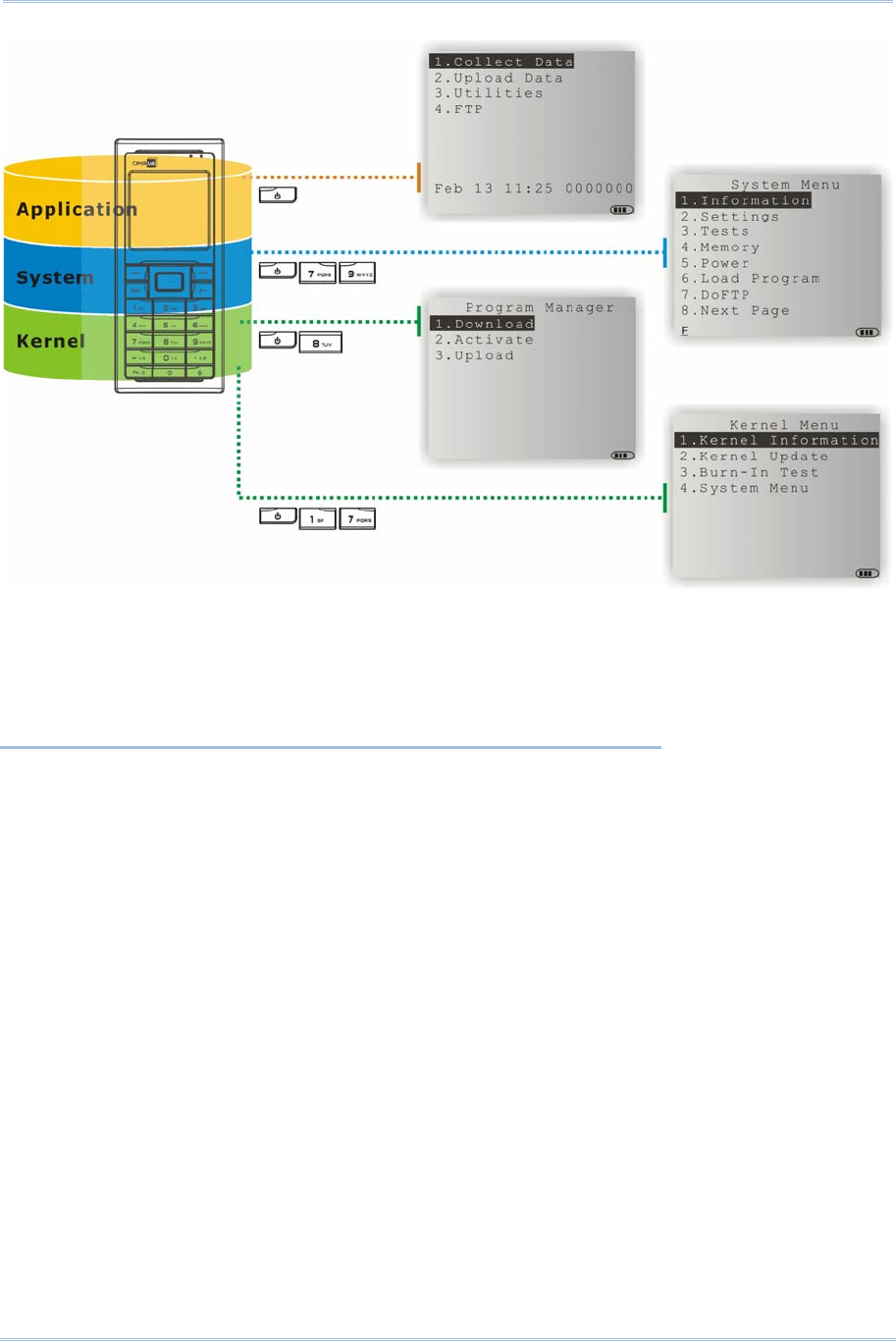
27
This chapter mainly describes the software inside the mobile computer. It consists of
three modules — Kernel, System, and Application; each has a function menu.
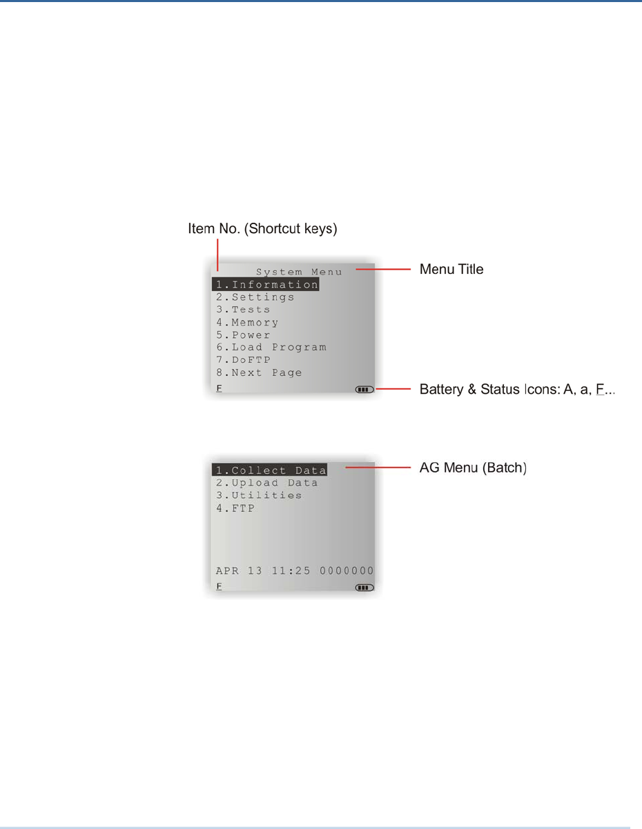
When a menu is displayed, you may select an item by either of the following ways:
Press the arrow keys [Up] and [Down] to move the highlight bar.
Press the number key that corresponds to the item number.
Follow the on-screen instructions to change a specific setting, or press [ESC] to
return to a previous page or menu.
On each screen, the bottom line displays status icons, such as:
The 4-bar battery icon indicates the current power status.
The status icon of input mode or function mode is controlled by the [Fn α] key.
Chapter 2
LEARNING SOFTWARE ARCHITECTURE
28
8200 Series Mobile Compute
r
Reference Manual
IN THIS CHAPTER
2.1 Application Module ..................................................... 29
2.2 System Configuration & Core ....................................... 31
Figure 7: Software Architecture
29
Chapter 2 錯誤! 使用 [常用] 索引標籤將
Heading 1 套用到您想要在此處顯示的文字。
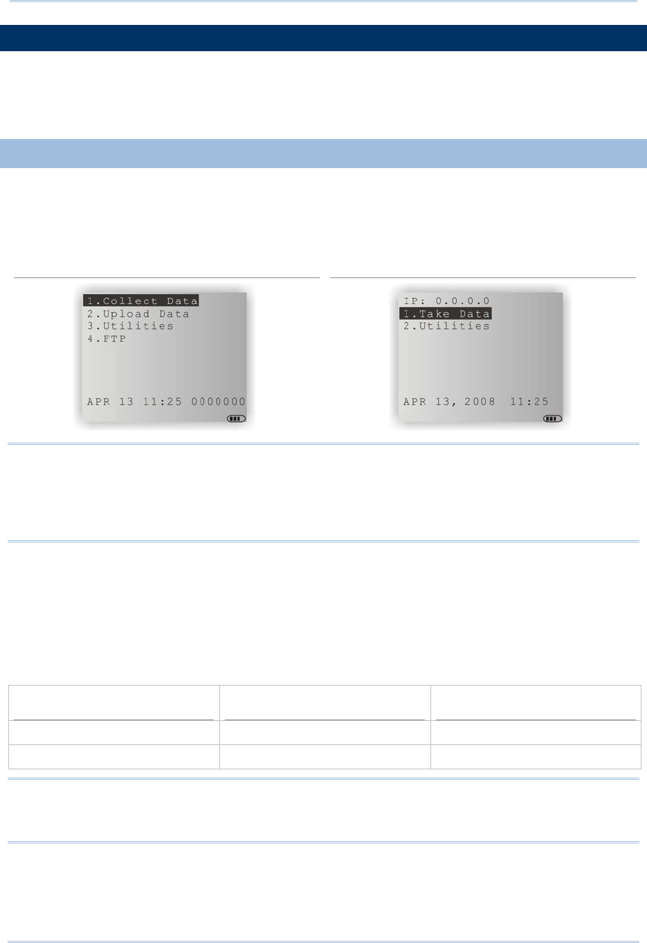
2.1 APPLICATION MODULE
The mobile computer ships with software package on the CD-ROM. It includes FORGE
Application Generator (batch and WLAN versions), MIRROR Emulator (VT and 5250
versions), download utilities, etc.
2.1.1 FORGE APPLICATION GENERATOR (AG)
For easy development of applications, the mobile computer is preloaded with AG runtime.
When you turn on the mobile computer, it displays the Main Menu of AG application, as
shown below.
Batch AG WLAN AG
Note: Batch AG supports automatically uploading data to a host computer when the
upload interface is properly configured. Once the mobile computer is connected via
the USB Virtual COM cable, there will be a moving hourglass icon displayed on the
upper-right corner of the screen, indicating the mobile computer is ready for auto
upload.
Before using the mobile computer to collect data, you need to configure the application
with the companion tool on your computer. This time-saving development tool helps
create application templates on your computer.
For details on the AG application, please refer to separate user manual.
Application Generator AG Runtime Companion Tool on PC End
Batch AG U8200.SHX ForgeAG.exe
WLAN AG WU8200.SHX AG8200WLAN.exe
Note: FORGE Application Generator (AG) software package includes
(1) a companion tool for quickly developing your application — Batch or WLAN AG;
(2) several download utilities to make it versatile in use.

30
8200 Series Mobile Compute
r
Reference Manual
2.1.2 MIRROR EMULATOR (CIPHERNET)
The mobile computer supports VT100/220 and IBM 5250 terminal emulation for
accessing a backend database. Instead of using FORGE Application Generator, you
may download the terminal emulation program, i.e. CipherNet Runtime, to the mobile
computer. Refer to 錯誤! 找不到參照來源。. Then, run individual companion tool on your
computer.
For details on the MIRROR Emulator application, please refer to separate user manuals.
Terminal Emulation CipherNet Runtime Companion Tool on PC End
VT100/220 82xx-VT.SHX CipherNet-VT.exe
IBM 5250 82xx-5250.SHX CipherNet-5250.exe
2.1.3 USER PROGRAM
You may need to develop your own application program. For developing custom
applications, CipherLab provides BASIC and C compilers through licensing. For detailed
information, please contact your sales representative.

31
Chapter 2 錯誤! 使用 [常用] 索引標籤將
Heading 1 套用到您想要在此處顯示的文字。
2.2 SYSTEM CONFIGURATION & CORE
For managing system configurations and multiple programs, each mobile computer
comes with System Menu, Program Manager, and Kernel Menu. Refer to the
following chapters on how to configure the 8200 Series Mobile Computer, regarding
system configurations and program download.
2.2.1 SYSTEM MENU
System Menu is bundled with BASIC Runtime or user programs that are written in “C”. It
is provided for system configuration, functionality testing, downloading font file and
program.
2.2.2 KERNEL
Kernel is the innermost core of the OS. It provides services for updating the kernel and
bootloader, and repairing the system.
2.2.3 PROGRAM MANAGER
Program Manager is part of the kernel. You may download as many as seven application
programs.

32
Model Designation 8200 8230 8260
Wireless
Communications Bluetooth Class 2 − √ √
802.11b/g − √ −
Readers Barcode Reader CCD (linear imager)
Standard Laser
2D Imager
Electrical
Characteristics Main Battery Rechargeable Li-ion battery – 3.7 V, 1200 mAh
Working Time Laser, one scan per 5 seconds, without backlight:
124 hours in batch mode
40 hours in Bluetooth mode (8260 in power
saving mode)
20 hours in Wi-Fi mode (1 broadcast packet per
second)
Backup Battery Rechargeable Lithium button cell – 3.0 V, 18 mAh
Data retention – at least 25 days
Power Adaptor Input: AC 100~240 V, 47/63 Hz
Output: DC 5 V, 3 A
Operating Temperature: 0 °C to 40 °C
Physical
Characteristics CPU 32-bit Toshiba CMOS type, 60 MHz
Memory Program memory – 8 MB flash
Data memory – onboard SRAM, options include 4
or 8 MB
Display Graphic LCD, 160 x 160 pixels, FSTN with LED
backlight programmable
Font size 6x8: 26 characters by 18 lines
Font size 8x16: 20 characters by 9 lines
Font size 12x12: 13 characters by 12 lines
Font size 16x16: 10 characters by 9 lines
Keypad 24 rubber keys, LED backlight programmable
Indicators Two dual-color LEDs – red/green and blue/green,
programmable
Vibrator 0.45G, programmable
Audio Integrated with one mono or stereo speaker
Bluetooth headset supported
Expansion Slot microSDHC, up to 8 GB
SPECIFICATIONS

33
8200 Series Mobile Compute
r
Reference Manual
Enclosure Material Rubber & ABS plastic
Dimensions CCD:
Laser/2D:
136 mm (L) 58 mm (W) 25 mm (H)
136 mm (L) 58 mm (W) 32 mm (H)
Weight Approx. 150 g (Laser, battery included)
Environmental
Characteristics Temperature Operating:
Storage:
Charging:
-10 °C to 60 °C
-20 °C to 70 °C
-10 °C to 40 °C
Humidity Operating:
Storage:
10% to 90% non-condensing
5% to 95% non-condensing
Impact Resistance 1.2 m, 5 drops per 6 sides
Tumble Test 1000 times at 1 meter
Splash / Dust
Resistance
IP 52
Electrostatic
Discharge
± 15 kV air discharge, ± 8 kV contact discharge
Programming Development Tools
C and BASIC
Software & Utilities
FORGE Application Generator (AG), AG utilities;
MIRROR Emulator (CipherNet) for VT100/220, IBM
5250 emulation;
Download utilities, testing tools, etc.
Accessories Pistol Grip
Spare rechargeable battery pack