CipherLab 9300 Terminal User Manual 9300 Mobile Computer
CipherLab Co., Ltd. Terminal 9300 Mobile Computer
UserManual.wiki
>
CipherLab
>
9300 User Manual
>
User Manual
Contents
1.
User Manual
2.
User Manual
User Manual
User Manual
Navigation menu
Upload a User Manual
Namespaces
Wiki Guide
HTML
PDF
Info
Views
User Manual
Discussion / Help
Navigation


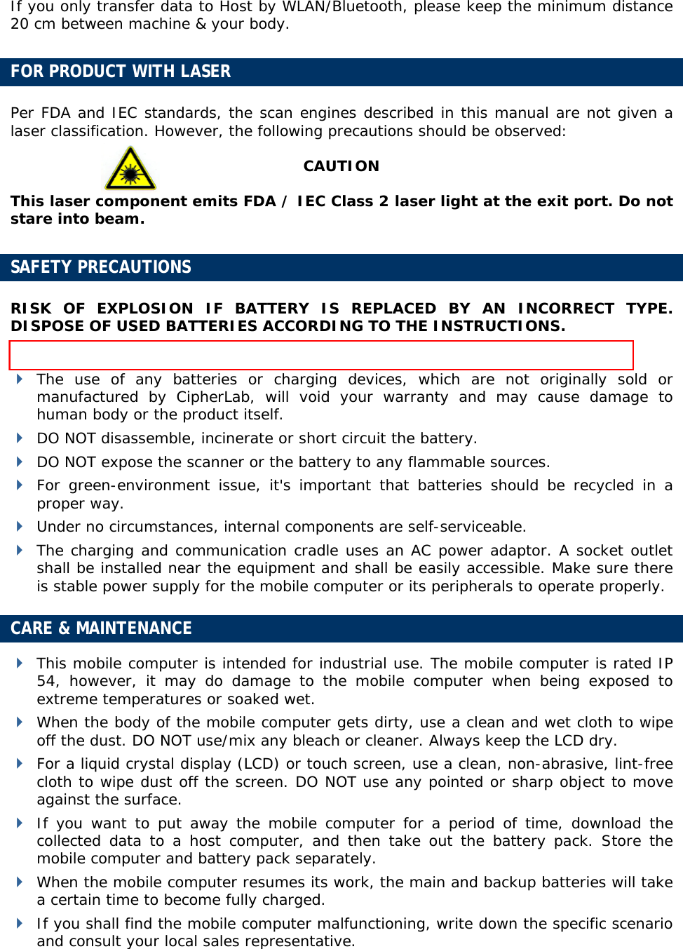


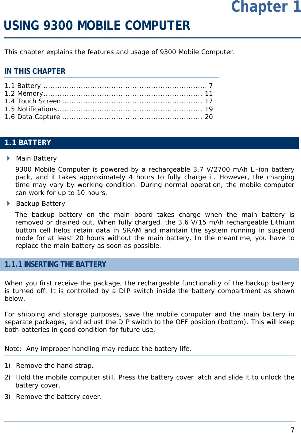
![9 Specifications 1.1.2 CHARGING THE BATTERY The main and backup batteries may not be charged to full for shipment. When you first receive the package, you will need to charge batteries to full before using the mobile computer. Note: To charge the batteries to full, it requires approximately 8 hours for the first time. After the initial charging, it takes only 4 hours to charge the batteries to full. Because the internal backup battery is constantly charged from the main battery, the initial charging requires inserting the battery pack to the mobile computer and then seating the mobile computer in the cradle for charging. This will have both the main and backup batteries charged at the same time. To charge the backup battery, make sure that you slide the DIP switch inside the battery compartment to the ON position. Note: For a new battery, make sure it is fully charged before use. Always prepare a spare battery pack, especially when you are on the road. 1.1.3 UNDERSTANDING THE BATTERY ICONS The battery pack is the only power source for the mobile computer to work. It also charges the backup battery on the main board so that the data stored in SRAM can be retained properly. Therefore, when the main battery charge goes low, you need to replace the battery pack with a charged one or charge it as soon as possible. Most of all, always save data before it is too late; you should backup important data on a regular basis. Double-tap a battery icon so that you can quickly access the [Power Properties] dialog box. Battery Status Icons Description Battery charge remaining in the main battery – The more bars, the more power in the main battery. Main battery is ready for charging. Main battery charge becomes low and needs charging. Main battery charge becomes very low and needs charging immediately. Warning: Data loss may occur with SRAM during low battery condition. Always save data before running out of power or keep a fresh battery for replacement.](https://usermanual.wiki/CipherLab/9300.User-Manual/User-Guide-1158379-Page-17.png)


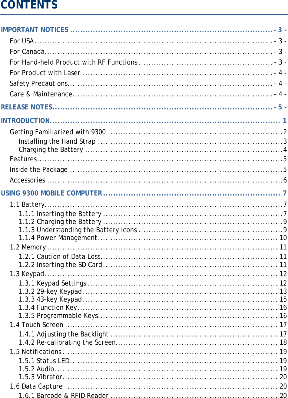
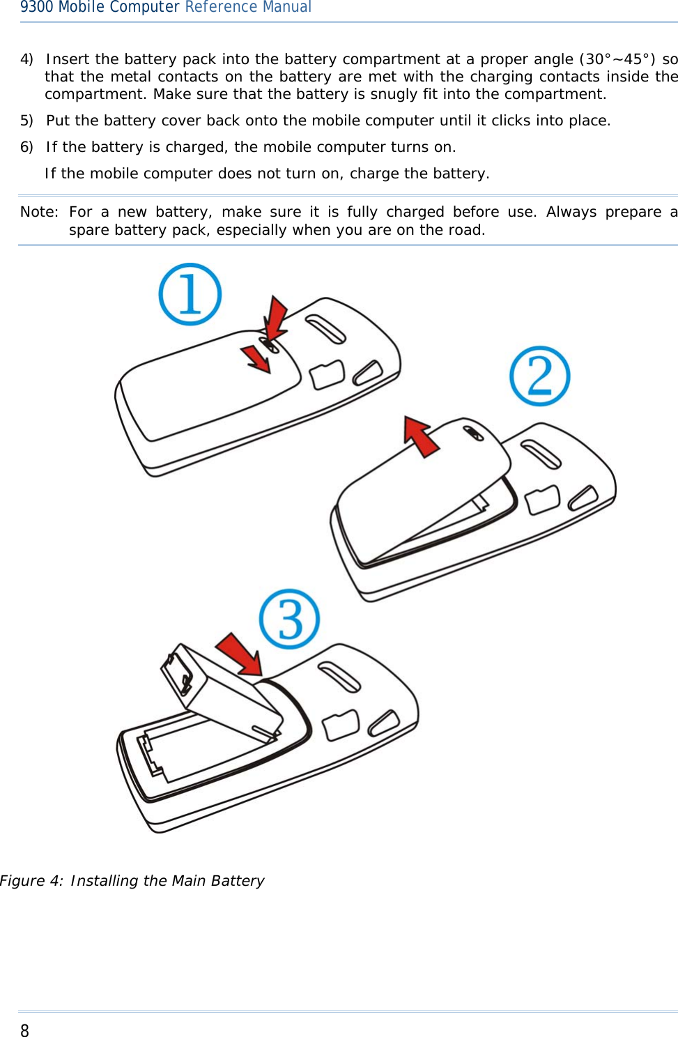
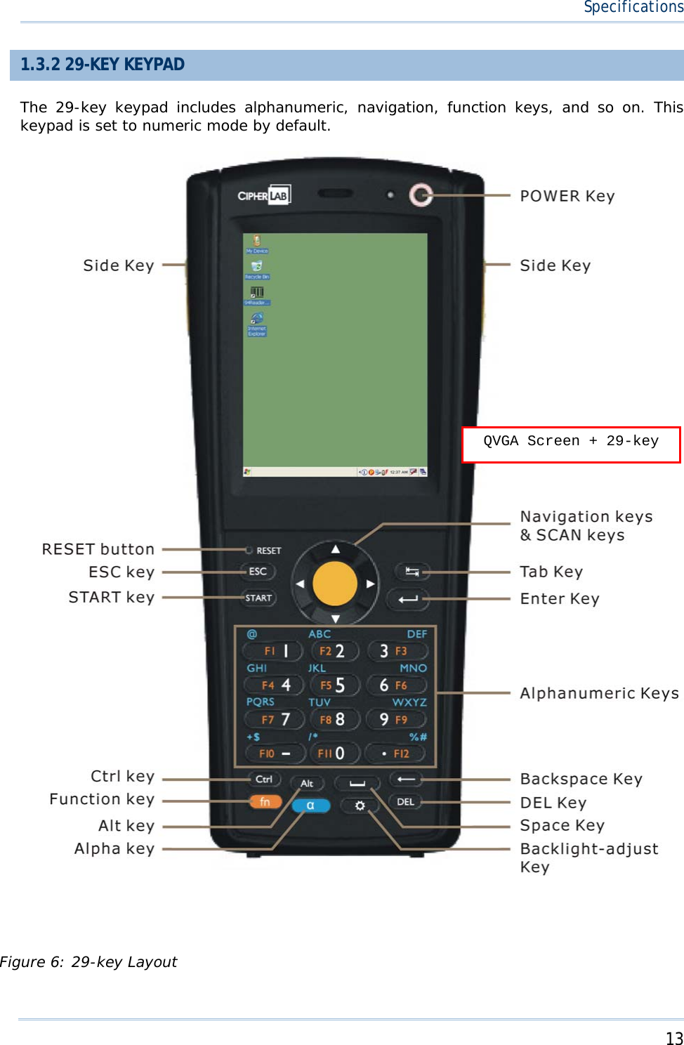
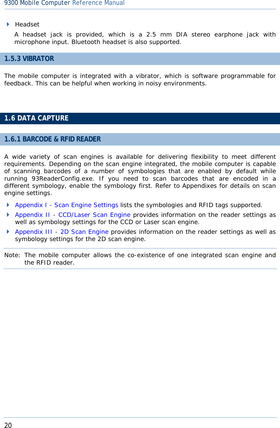
![12 9300 Mobile Computer Reference Manual 5) Replace the side plate and tighten the screws. Warning: Make sure the mobile computer is set to Suspend mode; otherwise, it may cause damage to the mobile computer. Figure 5: Inserting the SD Card REMOVING THE SD CARD If you wish to remove the SD card, simply push the card after removing the side plate. The SD card will be rejected automatically. 1.3 KEYPAD Silicon rubber has been chosen for their durability and prompt feedback. Note: Functionality of keys is application-dependent. 1.3.1 KEYPAD SETTINGS Press [FN] first, and then [0]. The LED backlight of keypad is turned off by default. It can be toggled ON/OFF by the key combination: [FN] + [0]. It is suggested to turn on the keypad backlight while working in a dark area; however, using backlight while on battery power will substantially reduce battery power. Go to Start > Settings > Control Panel and double-tap the Keyboard icon. The Character Repeat functionality is enabled by default. You may cancel the check box to disable it. When enabled, tap, hold, and drag the slider for a desired Repeat Delay and Repeat Rate.](https://usermanual.wiki/CipherLab/9300.User-Manual/User-Guide-1158379-Page-20.png)

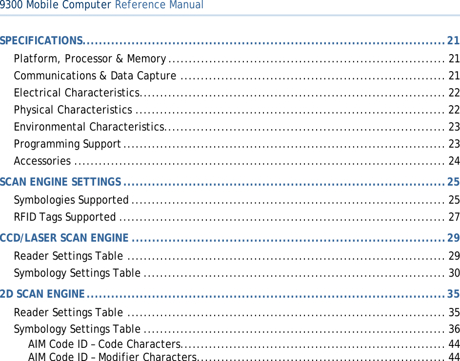
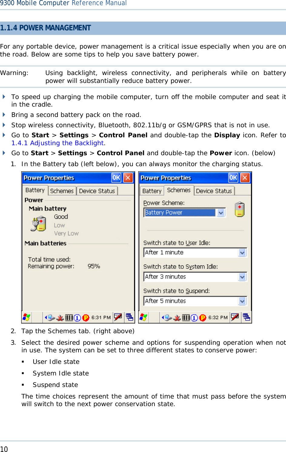
![14 9300 Mobile Computer Reference Manual ALPHA KEY This alphanumeric keypad is set to numeric mode by default. The Alpha key serves as a toggle among numeric, alpha (lower-case alphabetic), and ALPHA (upper-case alphabetic) input modes. Note: It is not necessary to hold down the [Alpha] key. The alpha icon will appear on the status bar in a sequence as shown below. Status Icon Alpha Key Input Mode N/A Numbers Press one time Small letters Press two times Capital letters Note: If you are using the software keypad via SIP, tap CAP (Caps Lock) to toggle between upper case and lower case alphabetic modes.](https://usermanual.wiki/CipherLab/9300.User-Manual/User-Guide-1158379-Page-22.png)
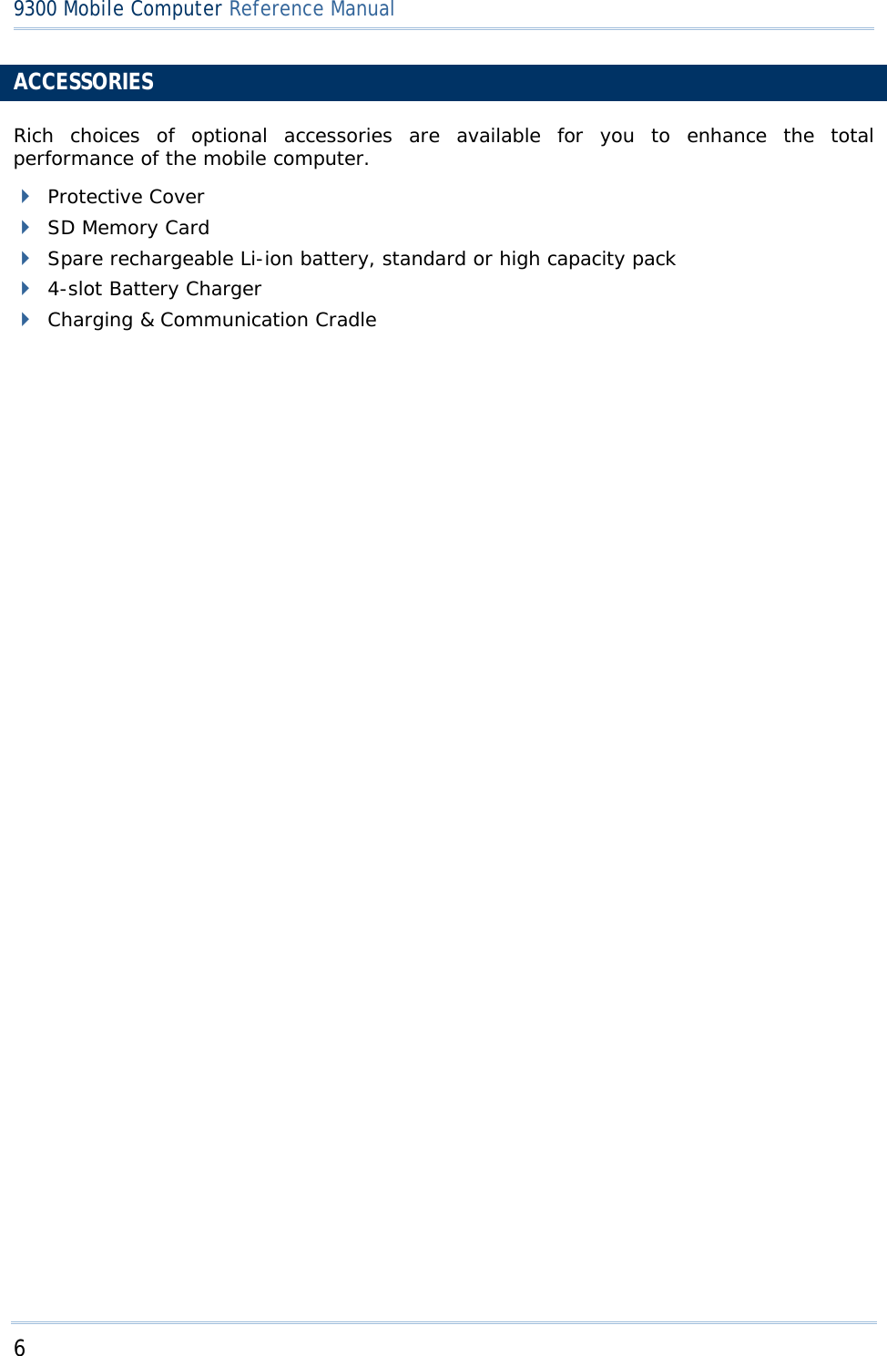
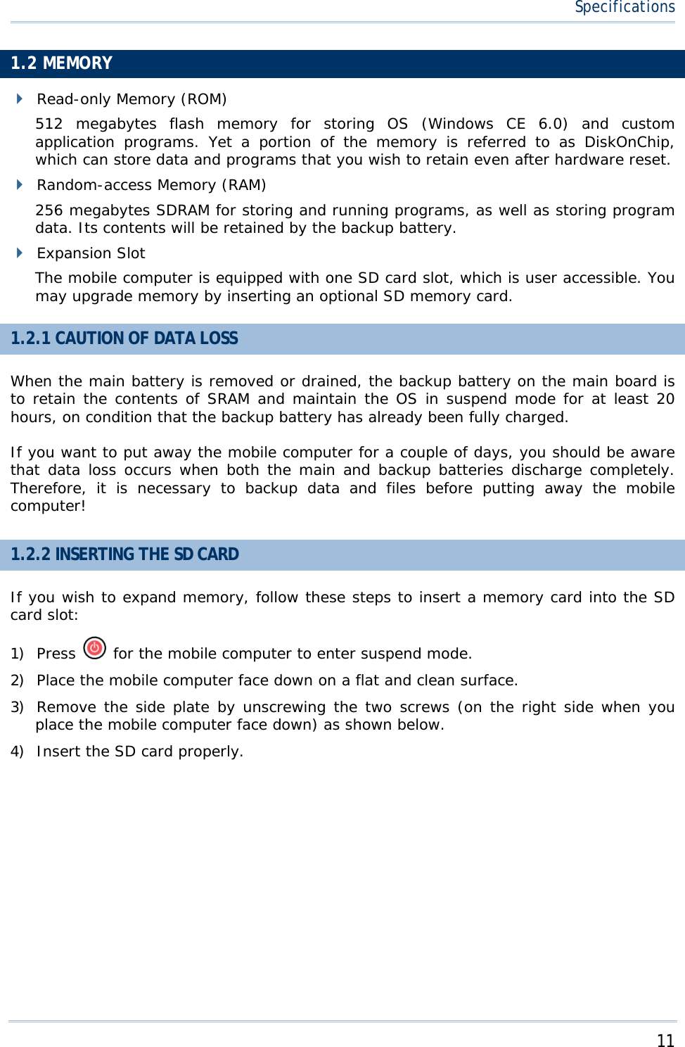
![16 9300 Mobile Computer Reference Manual 1.3.4 FUNCTION KEY The [FN] (function) key serves as a modifier key, and the functionality of each key combination is application-dependent. 1) To enable this modifier key, press [FN] on the keypad. A circular icon of the letter "F" will appear on the status bar. This modifier key is hold down as long as the icon is displayed. 2) Now press another key to get the value of key combination (say, press [1] to get the value of F1). The icon will go off now. 3) To get the value of another key combination modified by the [FN] key, repeat the above steps. 4) To abort the key modification, press [FN] again, and the icon will go off. Note: It is not necessary to hold down the [FN] key. Below is a list of the factory setting for a variety of key combinations. Key Combination Action [FN], Move text up one screenful (Page Up) [FN], Move text down one screenful (Page Down) [FN], Move to the beginning of screen or document (Home) [FN], Move to the end of screen or document (End) [FN], [0] Toggle ON/OFF the backlight of keypad only ([FN], [*@-] for 28-key) ([FN], [.$] for 59-key) Turn ON the backlight of LCD and decrease its luminosity ([FN], [.#$] for 28-key) ([FN], [- ;] for 59-key) Turn ON the backlight of LCD and increase its luminosity Note: Press the [FN] key first, and then press the second key for a specific function. 1.3.5 PROGRAMMABLE KEYS Depending on the keypad layout, a number of keys are user-definable, such as the programmable keys. They can be re-defined as another key or to serve as a shortcut key for launching a specific program. Refer to the Button Assignment Utility.](https://usermanual.wiki/CipherLab/9300.User-Manual/User-Guide-1158379-Page-24.png)
![17 Specifications Programmable Keys Other User-Definable Keys P1, P2 (28-key) SCAN key and four side triggers on each side of the touch screen P1, P2, P3 and P4 (59-key) Four side triggers on each side of the touch screen 1.4 TOUCH SCREEN The mobile computer comes with a 2.8" TFT graphic LCD, 320 by 240 pixels resolution (QVGA). The LED backlight of screen, which helps ease reading under dim environments, can be controlled manually and automatically. Warning: Using backlight while on battery power will substantially reduce battery power. It is suggested to dim the backlight while working in a well-lit area or automatically turn off the mobile computer when not in use. 1.4.1 ADJUSTING THE BACKLIGHT The LED backlight of the screen can be turned on and adjusted decreasingly or increasingly by the following key combinations. Keep pressing the key combination until the luminosity is decreased or increased to a desired level. Key Combination Action , ([Backlight], [DOWN] for 29-key) , ([[Backlight], [DOWN] for 43-key) Turn ON the backlight of LCD and decrease its luminosity , ([[Backlight], [UP] for 29-key) , ([[Backlight], [UP] for 43-key) Turn ON the backlight of LCD and increase its luminosity Note: Press the [FN] key first, and then press the second key for adjustment. Go to Start > Settings > Control Panel and double-tap the Display icon. 1. Tap the Backlight tab. (left below)](https://usermanual.wiki/CipherLab/9300.User-Manual/User-Guide-1158379-Page-25.png)
![18 9300 Mobile Computer Reference Manual 2. Select one or both of the check boxes to automatically turn off the LCD backlight when using batteries or external power. From the appropriate list, select the amount of time the device should be idle before the backlight is turned off. 3. Tap the [Advanced] button. 4. In the Settings tab (right above), you can select the luminosity of backlight when it is set to be automatically turned on by pressing any key or tapping the screen. Tap, hold, and drag the slider for AC and battery powered respectively. For more luminosity, move the slider to the right. 1.4.2 RE-CALIBRATING THE SCREEN This LCD is also a touch screen that can be calibrated through screen alignment. Go to Start > Settings > Control Panel and double-tap the Stylus icon. Tap the Calibration tab, and then tap the [Recalibrate] button.](https://usermanual.wiki/CipherLab/9300.User-Manual/User-Guide-1158379-Page-26.png)


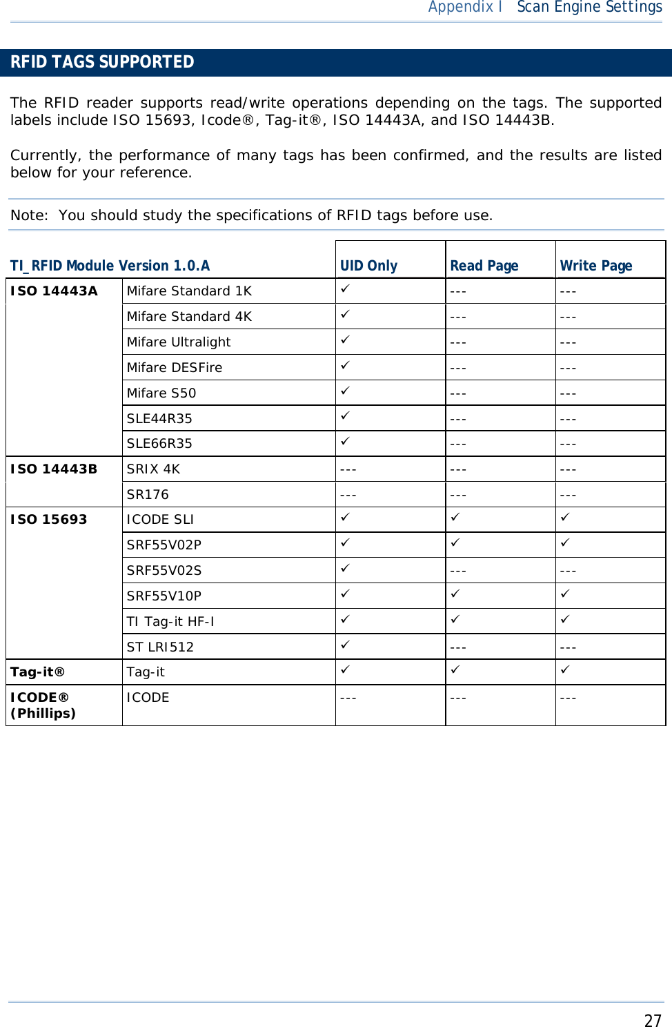
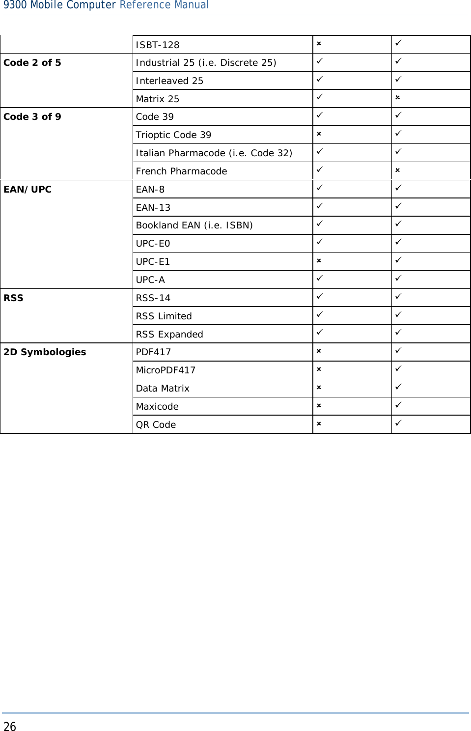
![25 Appendix I SCAN ENGINE SETTINGS The Reader Configuration Utility (93ReaderConfig.exe) allows configuring the following reader types, depending on the module equipped on your mobile computer: 1D CCD scan engine 1D Laser scan engine 2D scan engine RFID reader Options of different reader combination are allowed, such as 1D+RFID and 2D+RFID. For each combination, both readers can be initialized and ready for scanning at the same time (dual mode operation). For example, if you press the [SCAN] button while running the 93ReaderConfig utility on the mobile computer, it will read a barcode in position or an RFID tag in proximity depending on which one comes first. Note: (1) You cannot have 1D+2D scan engines installed on the mobile computer because they are both barcode readers! (2) You can run only one utility or application at a time to control the reader(s). For example, while running 93ReaderConfig.exe, you should not run Application Generator, STREAM Wireless Studio, MIRROR Browser, or any other application that uses ReaderDLL. SYMBOLOGIES SUPPORTED Varying by the scan engine installed, the supported symbologies or tag types are listed below. For details on configuring associated settings, please refer to each Appendix separately. CCD, Laser 2D Codabar 9 9 Code 11 8 9 Code 93 9 9 Composite Code 8 9 MSI 9 9 Plessey 9 8 Postal Codes 8 9 Telepen 9 8 Code 128 Code 128 9 9 EAN-128 9 9](https://usermanual.wiki/CipherLab/9300.User-Manual/User-Guide-1158379-Page-33.png)


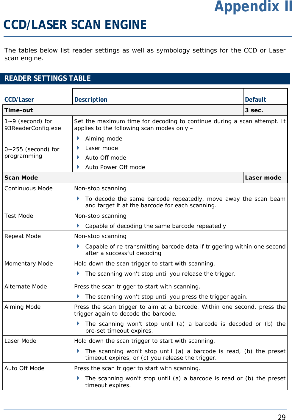
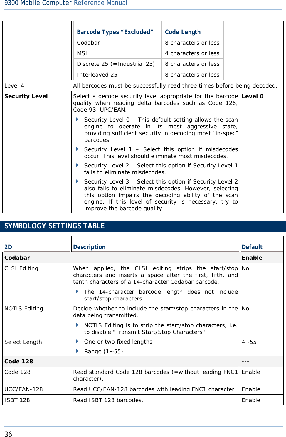
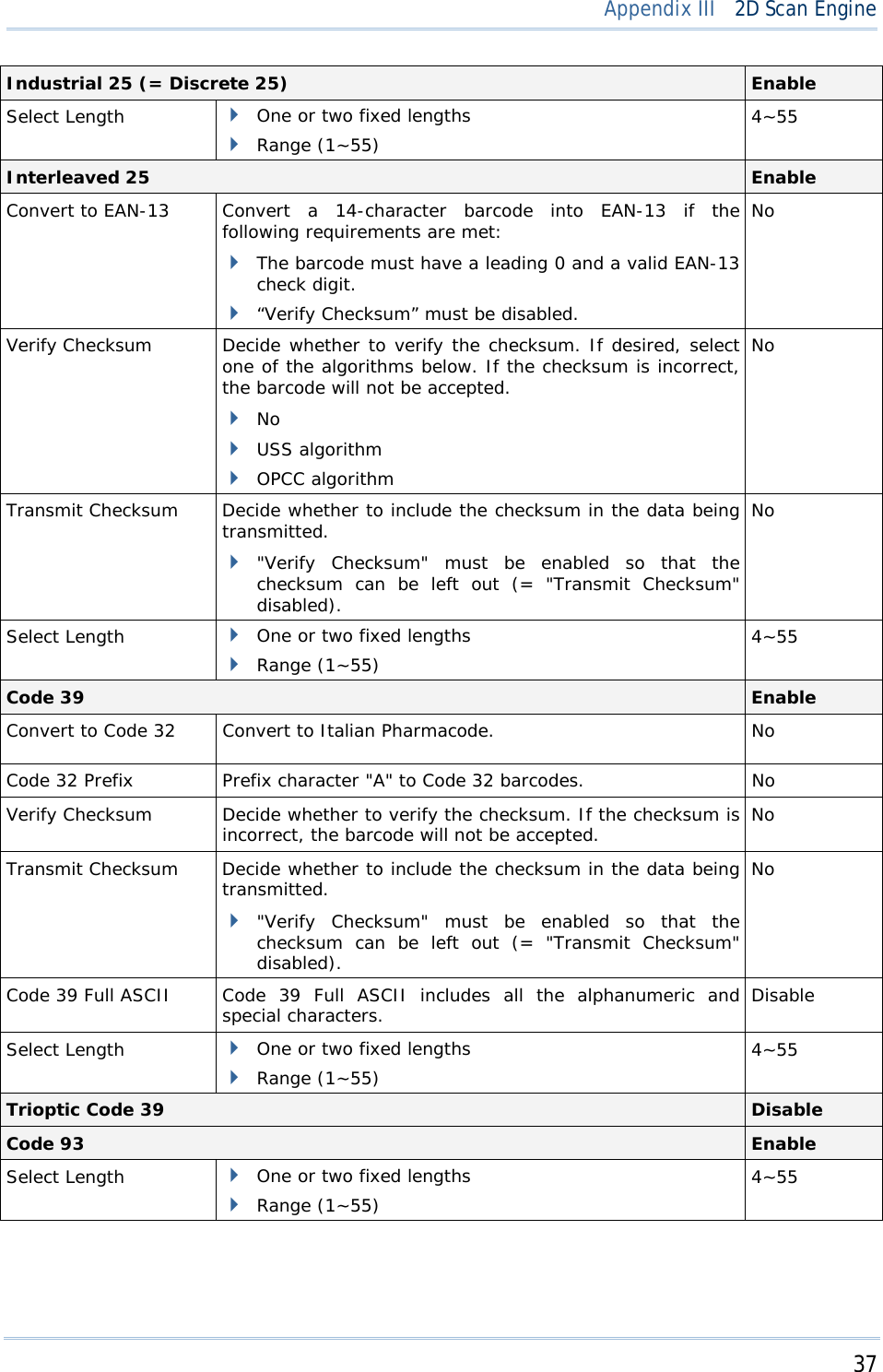
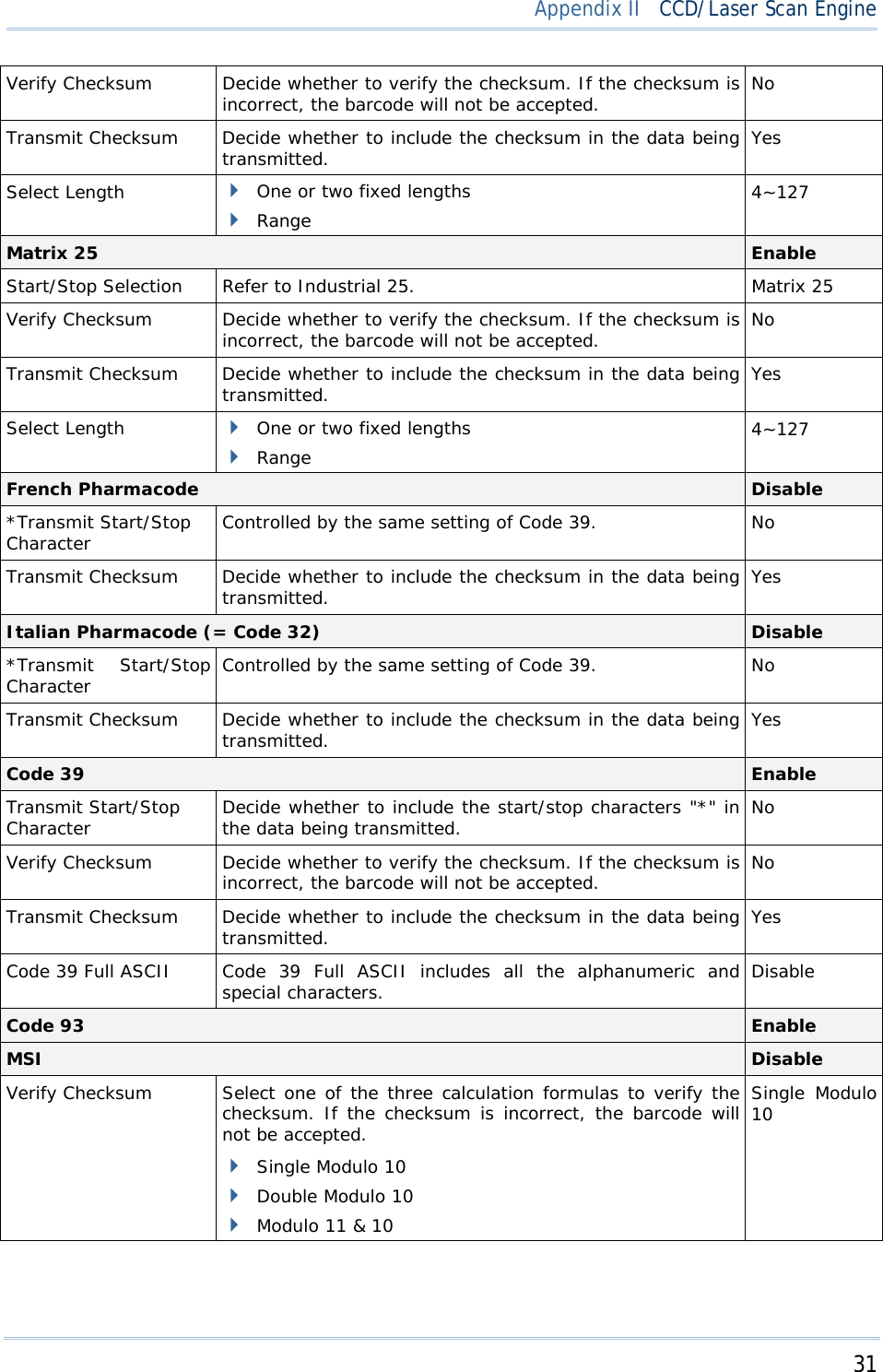
![30 9300 Mobile Computer Reference Manual Auto Power Off Mode Press the scan trigger to start with scanning. The scanning won't stop until the preset timeout expires, and, the preset timeout period re-counts after each successful decoding. Read Redundancy None None No redundancy means one successful decoding will make the reading valid and induce the "READER Event". One time, Two times, or Three times The higher the reading security is (that is, the more redundancy the user selects), the slower the reading speed gets. If "Three Times" is selected, it will take a total of four consecutive successful decodings of the same barcode to make the reading valid. SYMBOLOGY SETTINGS TABLE CCD/Laser Description Default Codabar Enable Select Start/Stop Characters If "Transmit Start/Stop Characters" is desired, select one set: abcd / abcd abcd / tn*e ABCD / ABCD ABCD / TN*E abcd / abcd Transmit Start/Stop Characters Decide whether to include the start/stop characters in the data being transmitted. No Code 128 Enable EAN-128 Enable Transmit Code ID Decide whether to include Code ID (“]C1”) will be included in the data being transmitted. No Industrial 25 (= Discrete 25) Enable Start/Stop Selection This decides the readability of all 2 of 5 symbology variants. For example, flight tickets actually use an Industrial 2 of 5 barcode but with Interleaved 2 of 5 start/stop pattern. In order to read this barcode, the start/stop pattern selection parameter of Industrial 2 of 5 should set to "Interleaved 25". Industrial 25 Verify Checksum Decide whether to verify the checksum. If the checksum is incorrect, the barcode will not be accepted. No Transmit Checksum Decide whether to include the checksum in the data being transmitted. Yes Select Length One or two fixed lengths Range 4~127 Interleaved 25 Enable Start/Stop Selection Refer to Industrial 25. Interleaved 25](https://usermanual.wiki/CipherLab/9300.User-Manual/User-Guide-1158379-Page-38.png)

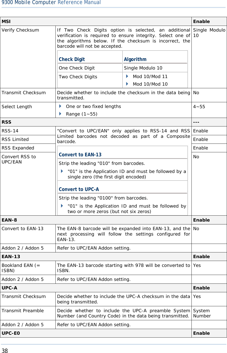
![32 9300 Mobile Computer Reference Manual Transmit Checksum Decide whether to include the checksum in the data being transmitted. Last digit not transmitted Both digits transmitted Both digits not transmitted Both digits transmitted Select Length One or two fixed lengths Range 4~127 Negative Barcode Disable Plessey Disable Convert to UK Plessey When applied, each occurrence of the character "A" in the barcode data will be replaced by the character "X". No Transmit Checksum Decide whether to include the checksum (2 digits) in the data being transmitted. Yes Telepen Disable Original Telepen (Numeric) The original Telepen includes numeric characters. Yes AIM Telepen (Full ASCII) AIM Telepen (Full ASCII) includes all the alphanumeric and special characters. No RSS-14 Disable Transmit Code ID Decide whether to include Code ID (“]e0”) will be included in the data being transmitted. Yes Transmit Application ID Decide whether to include the Application ID ("01") in the data being transmitted. Yes Transmit Checksum Decide whether to include the checksum in the data being transmitted. Yes RSS Limited Disable Transmit Code ID Refer to RSS-14. Yes Transmit Application ID Refer to RSS-14. Yes Transmit Checksum Refer to RSS-14. Yes RSS Expanded Disable Transmit Code ID Refer to RSS-14. Yes EAN-8 Enable Convert to EAN-13 The EAN-8 barcode will be expanded into EAN-13, and the next processing will follow the settings configured for EAN-13. No Transmit Checksum Decide whether to include the checksum in the data being transmitted. Yes Addon 2 / Addon 5 Decide whether to decode EAN-8 with supplementals. No EAN-13 / UPC-A Enable ISBN Conversion The EAN-13 barcode starting with 978 and 979 will be converted to ISBN. No](https://usermanual.wiki/CipherLab/9300.User-Manual/User-Guide-1158379-Page-40.png)
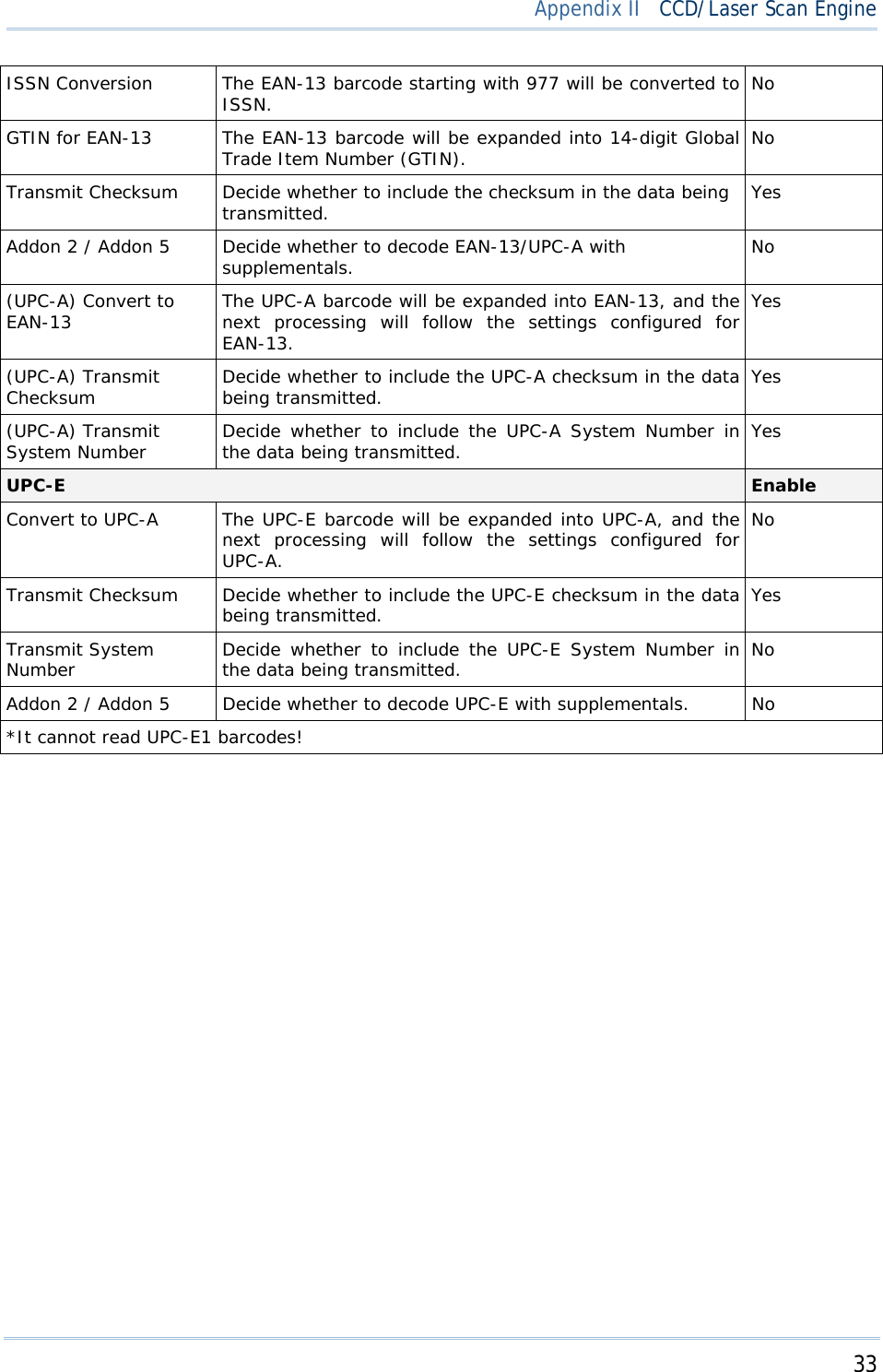

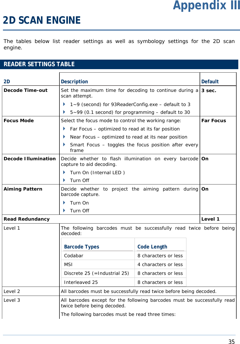


![41 Appendix III 2D Scan Engine When applied, the MicroPDF417 barcodes are transmitted with one of these prefixes: The first codeword of MicroPDF417 is 903-907, 912, 914, 915: The original Code ID "]L3" will be changed to "]C1". The first codeword of MicroPDF417 is 908 or 909: The original Code ID "]L4" will be changed to "]C2". The first codeword of MicroPDF417 is 910 or 911: The original Code ID "]L5" will be changed to "]C0". Data Matrix Enable Maxicode Enable QR Code Enable 2D Symbologies - Macro PDF --- Macro PDF is a special feature for concatenating multiple PDF barcodes into one file, known as Macro PDF417 or Macro MicroPDF417. Transmit/Decode Mode Decide how to handle Macro PDF decoding. Buffer All Symbols / Transmit Macro PDF When Complete Transmit all decoded data from an entire Macro PDF sequence only when the entire sequence is scanned and decoded. If the decoded data exceeds the limit of 50 symbols, no transmission because the entire sequence was not scanned! Transmit Any Symbol in Set / No Particular Order Transmit data from each Macro PDF symbol as decoded, regardless of the sequence. Passthrough All Symbols Transmit and decode all Macro PDF symbols and perform no processing. In this mode, the host is responsible for detecting and parsing the Macro PDF sequences. Passthrough All Symbols ESC Characters When enabled, it uses the backslash "\" as an Escape character for systems that can process transmissions containing special data sequences. It will format special data according to the Global Label Identifier (GLI) protocol, which only affects the data portion of a Macro PDF symbol transmission. The Control Header, if enabled, is always sent with GLI formatting. None](https://usermanual.wiki/CipherLab/9300.User-Manual/User-Guide-1158379-Page-49.png)

![43 Appendix III 2D Scan Engine Optimized for JPEG Quality Decide whether JPEG images are optimized for quality. Cancel the check box so that JPEG images are optimized for size. Enable Select JPEG Quality Set a value from 5 to 100, where “100” represents the highest quality image. 65 Select JPEG Size Set a value from 5 to 150, which represents the file size in multiples of 1024 bytes (1K). For example, setting this value to 8 permits the file size to be as large as 8192 bytes. 40 Bits per Pixel Select the number of significant bits per pixel (BPP) to use when capturing an image. 1 bit per pixel (for black and white images) 4 BPP (to assign 1 of 16 levels of grey to each pixel) 8 BPP (to assign 1 of 256 levels of grey to each pixel) 8 Note: (1) For JPEG files, these BPP settings are ignored for it always uses 8 bits per pixel! (2) When the image capture feature is enabled, press the [SCAN] button and it will capture an image instead of reading a barcode. Miscellaneous Options --- Transmit Code ID Decide whether to include AIM Code ID in the beginning of data. Each AIM Code ID contains the three-character string “]cm” – ] = Flag Character (ASCII 93) c = Code Character (see below) m = Modifier Character (see below) Disable](https://usermanual.wiki/CipherLab/9300.User-Manual/User-Guide-1158379-Page-51.png)
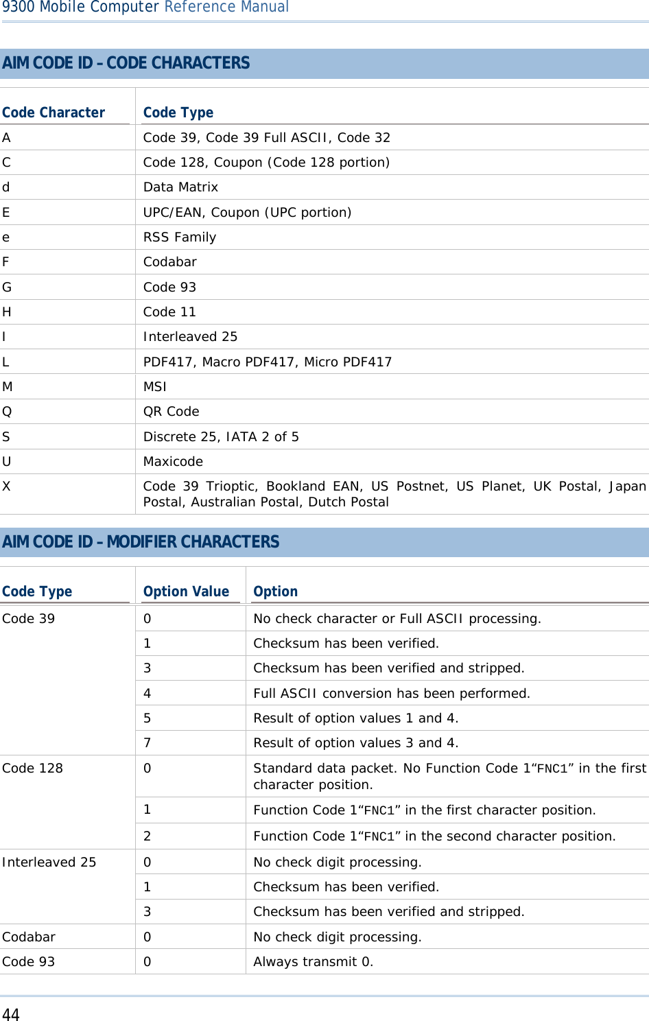
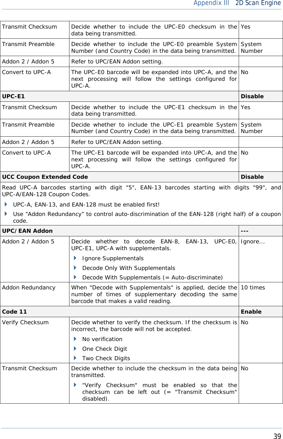
![45 Appendix III 2D Scan Engine 0 Modulo 10 check digit verified and transmitted. MSI 1 Modulo 10 check digit verified but not transmitted. Discrete 25 0 Always transmit 0. 0 Standard data packet in full EAN country code format, which is 13 digits for UPC-A and UPC-E (not including supplemental data). 3 Standard data packet with two-digit or five-digit supplemental data. 4 EAN-8 data packet. UPC/EAN A UPC-A with Addon 2 barcode, 012345678905-10, is transmitted to the host as a 18-character string, ]E3001234567890510. Bookland EAN 0 Always transmit 0. Trioptic Code 39 0 Always transmit 0. 0 Single check digit (has been verified.) 1 Two check digits (has been verified.) Code 11 3 Checksum has been verified but not transmitted. 0 Always transmit 0. RSS Family RSS-14 and RSS Limited will be transmitted with an Application Identifier “01”. For example, an RSS-14 barcode, 100123456788902, is transmitted as ]e001100123456788902. Note: In UCC/EAN-128 emulation mode, RSS is transmitted using Code 128 rules (i.e. “]C1”). Native mode transmission 0 Standard data packet 1 Data packet containing the data following an encoded symbol separator character. 2 Data packet containing the data following an escape mechanism character. The data packet does not support the ECI protocol. 3 Data packet containing the data following an escape mechanism character. The data packet supports the ECI protocol. UCC/EAN-128 emulation EAN.UCC Composites (RSS, UCC/EAN-128, 2D portion of UPC composite) 1 Data packet is a UCC/EAN-128 barcode (i.e. data is preceded with “]JC1”). Note: UPC portion of composite is transmitted using UPC rules. PDF417, Micro PDF417 0 Scan engine is set to conform to protocol defined in 1994 PDF417 symbology specifications. When this option is transmitted, the receiver cannot reliably determine whether ECIs have been invoked or whether data byte 92DEC has been doubled in](https://usermanual.wiki/CipherLab/9300.User-Manual/User-Guide-1158379-Page-53.png)
![46 9300 Mobile Computer Reference Manual transmission. 1 Scan engine is set to follow the ECI protocol (Extended Channel Interpretation). All data characters 92DEC are doubled. 2 Scan engine is set for Basic Channel operation (no escape character transmission protocol). Data characters 92DEC are not doubled. When decoders are set to this mode, unbuffered Macro symbols and symbols requiring the decoder to convey ECI escape sequences cannot be transmitted. 3 The barcode contains a UCC/EAN-128 symbol, and the first codeword is 903-907, 912, 914, 915. 4 The barcode contains a UCC/EAN-128 symbol, and the first codeword is in the range 908-909. 5 The barcode contains a UCC/EAN-128 symbol, and the first codeword is in the range 910-911. A PDF417 barcode, ABCD, with no transmission protocol enabled, is transmitted as ]L2ABCD. 0 ECC 000-140, not supported. 1 ECC 200. 2 ECC 200, FNC1 in first or fifth position. 3 ECC 200, FNC1 in second or sixth position. 4 ECC 200, ECI protocol implemented. 5 ECC 200, FNC1 in first or fifth position, ECI protocol implemented. Data Matrix 6 ECC 200, FNC1 in second or sixth position, ECI protocol implemented. 0 Mode 4 or 5 1 Mode 2 or 3 2 Mode 4 or 5, ECI protocol implemented. Maxicode 3 Mode 2 or 3, ECI protocol implemented in secondary message. 0 Model 1 1 Model 2, ECI protocol not implemented. 2 Model 2, ECI protocol implemented. 3 Model 2, ECI protocol not implemented, FNC1 implied in first position. 4 Model 2, ECI protocol implemented, FNC1 implied in first position. 5 Model 2, ECI protocol not implemented, FNC1 implied in second position. QR Code 6 Model 2, ECI protocol implemented, FNC1 implied in second position](https://usermanual.wiki/CipherLab/9300.User-Manual/User-Guide-1158379-Page-54.png)


![9 Specifications 1.1.2 CHARGING THE BATTERY The main and backup batteries may not be charged to full for shipment. When you first receive the package, you will need to charge batteries to full before using the mobile computer. Note: To charge the batteries to full, it requires approximately 8 hours for the first time. After the initial charging, it takes only 4 hours to charge the batteries to full. Because the internal backup battery is constantly charged from the main battery, the initial charging requires inserting the battery pack to the mobile computer and then seating the mobile computer in the cradle for charging. This will have both the main and backup batteries charged at the same time. To charge the backup battery, make sure that you slide the DIP switch inside the battery compartment to the ON position. Note: For a new battery, make sure it is fully charged before use. Always prepare a spare battery pack, especially when you are on the road. 1.1.3 UNDERSTANDING THE BATTERY ICONS The battery pack is the only power source for the mobile computer to work. It also charges the backup battery on the main board so that the data stored in SRAM can be retained properly. Therefore, when the main battery charge goes low, you need to replace the battery pack with a charged one or charge it as soon as possible. Most of all, always save data before it is too late; you should backup important data on a regular basis. Double-tap a battery icon so that you can quickly access the [Power Properties] dialog box. Battery Status Icons Description Battery charge remaining in the main battery – The more bars, the more power in the main battery. Main battery is ready for charging. Main battery charge becomes low and needs charging. Main battery charge becomes very low and needs charging immediately. Warning: Data loss may occur with SRAM during low battery condition. Always save data before running out of power or keep a fresh battery for replacement.](https://usermanual.wiki/CipherLab/9300.User-Manual/User-Guide-1158411-Page-17.png)
![12 9300 Mobile Computer Reference Manual 5) Replace the side plate and tighten the screws. Warning: Make sure the mobile computer is set to Suspend mode; otherwise, it may cause damage to the mobile computer. Figure 5: Inserting the SD Card REMOVING THE SD CARD If you wish to remove the SD card, simply push the card after removing the side plate. The SD card will be rejected automatically. 1.3 KEYPAD Silicon rubber has been chosen for their durability and prompt feedback. Note: Functionality of keys is application-dependent. 1.3.1 KEYPAD SETTINGS Press [FN] first, and then [0]. The LED backlight of keypad is turned off by default. It can be toggled ON/OFF by the key combination: [FN] + [0]. It is suggested to turn on the keypad backlight while working in a dark area; however, using backlight while on battery power will substantially reduce battery power. Go to Start > Settings > Control Panel and double-tap the Keyboard icon. The Character Repeat functionality is enabled by default. You may cancel the check box to disable it. When enabled, tap, hold, and drag the slider for a desired Repeat Delay and Repeat Rate.](https://usermanual.wiki/CipherLab/9300.User-Manual/User-Guide-1158411-Page-20.png)
![14 9300 Mobile Computer Reference Manual ALPHA KEY This alphanumeric keypad is set to numeric mode by default. The Alpha key serves as a toggle among numeric, alpha (lower-case alphabetic), and ALPHA (upper-case alphabetic) input modes. Note: It is not necessary to hold down the [Alpha] key. The alpha icon will appear on the status bar in a sequence as shown below. Status Icon Alpha Key Input Mode N/A Numbers Press one time Small letters Press two times Capital letters Note: If you are using the software keypad via SIP, tap CAP (Caps Lock) to toggle between upper case and lower case alphabetic modes.](https://usermanual.wiki/CipherLab/9300.User-Manual/User-Guide-1158411-Page-22.png)

![16 9300 Mobile Computer Reference Manual 1.3.4 FUNCTION KEY The [FN] (function) key serves as a modifier key, and the functionality of each key combination is application-dependent. 1) To enable this modifier key, press [FN] on the keypad. A circular icon of the letter "F" will appear on the status bar. This modifier key is hold down as long as the icon is displayed. 2) Now press another key to get the value of key combination (say, press [1] to get the value of F1). The icon will go off now. 3) To get the value of another key combination modified by the [FN] key, repeat the above steps. 4) To abort the key modification, press [FN] again, and the icon will go off. Note: It is not necessary to hold down the [FN] key. Below is a list of the factory setting for a variety of key combinations. Key Combination Action [FN], Move text up one screenful (Page Up) [FN], Move text down one screenful (Page Down) [FN], Move to the beginning of screen or document (Home) [FN], Move to the end of screen or document (End) [FN], [0] Toggle ON/OFF the backlight of keypad only ([FN], [*@-] for 28-key) ([FN], [.$] for 59-key) Turn ON the backlight of LCD and decrease its luminosity ([FN], [.#$] for 28-key) ([FN], [- ;] for 59-key) Turn ON the backlight of LCD and increase its luminosity Note: Press the [FN] key first, and then press the second key for a specific function. 1.3.5 PROGRAMMABLE KEYS Depending on the keypad layout, a number of keys are user-definable, such as the programmable keys. They can be re-defined as another key or to serve as a shortcut key for launching a specific program. Refer to the Button Assignment Utility.](https://usermanual.wiki/CipherLab/9300.User-Manual/User-Guide-1158411-Page-24.png)
![17 Specifications Programmable Keys Other User-Definable Keys P1, P2 (28-key) SCAN key and four side triggers on each side of the touch screen P1, P2, P3 and P4 (59-key) Four side triggers on each side of the touch screen 1.4 TOUCH SCREEN The mobile computer comes with a 2.8" TFT graphic LCD, 320 by 240 pixels resolution (QVGA). The LED backlight of screen, which helps ease reading under dim environments, can be controlled manually and automatically. Warning: Using backlight while on battery power will substantially reduce battery power. It is suggested to dim the backlight while working in a well-lit area or automatically turn off the mobile computer when not in use. 1.4.1 ADJUSTING THE BACKLIGHT The LED backlight of the screen can be turned on and adjusted decreasingly or increasingly by the following key combinations. Keep pressing the key combination until the luminosity is decreased or increased to a desired level. Key Combination Action , ([Backlight], [DOWN] for 29-key) , ([[Backlight], [DOWN] for 43-key) Turn ON the backlight of LCD and decrease its luminosity , ([[Backlight], [UP] for 29-key) , ([[Backlight], [UP] for 43-key) Turn ON the backlight of LCD and increase its luminosity Note: Press the [FN] key first, and then press the second key for adjustment. Go to Start > Settings > Control Panel and double-tap the Display icon. 1. Tap the Backlight tab. (left below)](https://usermanual.wiki/CipherLab/9300.User-Manual/User-Guide-1158411-Page-25.png)
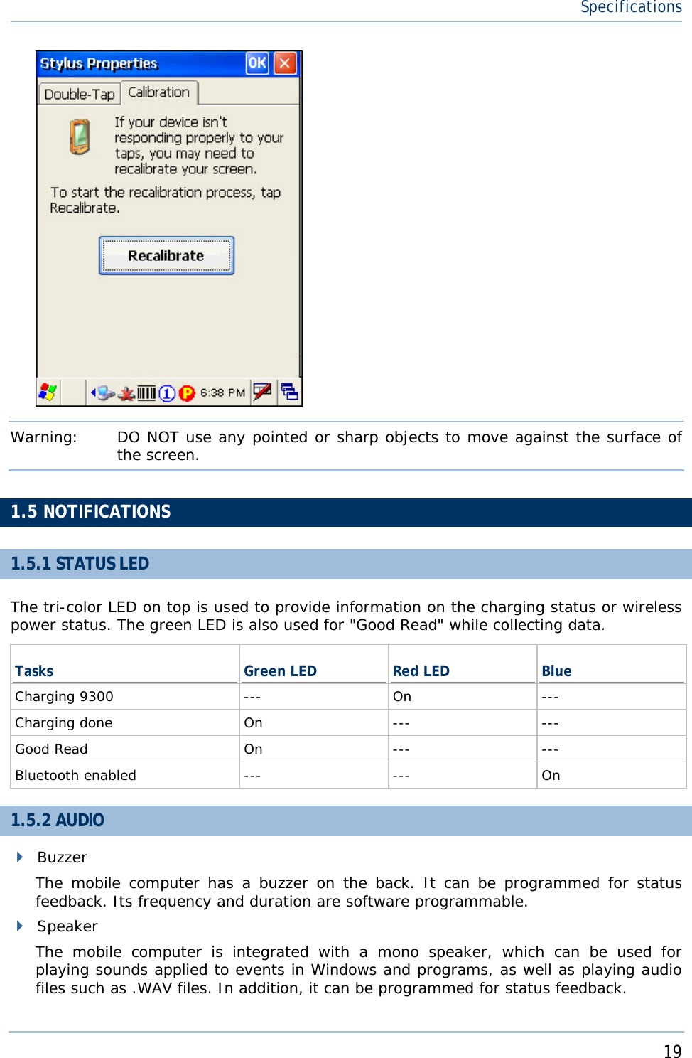
![18 9300 Mobile Computer Reference Manual 2. Select one or both of the check boxes to automatically turn off the LCD backlight when using batteries or external power. From the appropriate list, select the amount of time the device should be idle before the backlight is turned off. 3. Tap the [Advanced] button. 4. In the Settings tab (right above), you can select the luminosity of backlight when it is set to be automatically turned on by pressing any key or tapping the screen. Tap, hold, and drag the slider for AC and battery powered respectively. For more luminosity, move the slider to the right. 1.4.2 RE-CALIBRATING THE SCREEN This LCD is also a touch screen that can be calibrated through screen alignment. Go to Start > Settings > Control Panel and double-tap the Stylus icon. Tap the Calibration tab, and then tap the [Recalibrate] button.](https://usermanual.wiki/CipherLab/9300.User-Manual/User-Guide-1158411-Page-26.png)


![25 Appendix I SCAN ENGINE SETTINGS The Reader Configuration Utility (93ReaderConfig.exe) allows configuring the following reader types, depending on the module equipped on your mobile computer: 1D CCD scan engine 1D Laser scan engine 2D scan engine RFID reader Options of different reader combination are allowed, such as 1D+RFID and 2D+RFID. For each combination, both readers can be initialized and ready for scanning at the same time (dual mode operation). For example, if you press the [SCAN] button while running the 93ReaderConfig utility on the mobile computer, it will read a barcode in position or an RFID tag in proximity depending on which one comes first. Note: (1) You cannot have 1D+2D scan engines installed on the mobile computer because they are both barcode readers! (2) You can run only one utility or application at a time to control the reader(s). For example, while running 93ReaderConfig.exe, you should not run Application Generator, STREAM Wireless Studio, MIRROR Browser, or any other application that uses ReaderDLL. SYMBOLOGIES SUPPORTED Varying by the scan engine installed, the supported symbologies or tag types are listed below. For details on configuring associated settings, please refer to each Appendix separately. CCD, Laser 2D Codabar 9 9 Code 11 8 9 Code 93 9 9 Composite Code 8 9 MSI 9 9 Plessey 9 8 Postal Codes 8 9 Telepen 9 8 Code 128 Code 128 9 9 EAN-128 9 9](https://usermanual.wiki/CipherLab/9300.User-Manual/User-Guide-1158411-Page-33.png)


![30 9300 Mobile Computer Reference Manual Auto Power Off Mode Press the scan trigger to start with scanning. The scanning won't stop until the preset timeout expires, and, the preset timeout period re-counts after each successful decoding. Read Redundancy None None No redundancy means one successful decoding will make the reading valid and induce the "READER Event". One time, Two times, or Three times The higher the reading security is (that is, the more redundancy the user selects), the slower the reading speed gets. If "Three Times" is selected, it will take a total of four consecutive successful decodings of the same barcode to make the reading valid. SYMBOLOGY SETTINGS TABLE CCD/Laser Description Default Codabar Enable Select Start/Stop Characters If "Transmit Start/Stop Characters" is desired, select one set: abcd / abcd abcd / tn*e ABCD / ABCD ABCD / TN*E abcd / abcd Transmit Start/Stop Characters Decide whether to include the start/stop characters in the data being transmitted. No Code 128 Enable EAN-128 Enable Transmit Code ID Decide whether to include Code ID (“]C1”) will be included in the data being transmitted. No Industrial 25 (= Discrete 25) Enable Start/Stop Selection This decides the readability of all 2 of 5 symbology variants. For example, flight tickets actually use an Industrial 2 of 5 barcode but with Interleaved 2 of 5 start/stop pattern. In order to read this barcode, the start/stop pattern selection parameter of Industrial 2 of 5 should set to "Interleaved 25". Industrial 25 Verify Checksum Decide whether to verify the checksum. If the checksum is incorrect, the barcode will not be accepted. No Transmit Checksum Decide whether to include the checksum in the data being transmitted. Yes Select Length One or two fixed lengths Range 4~127 Interleaved 25 Enable Start/Stop Selection Refer to Industrial 25. Interleaved 25](https://usermanual.wiki/CipherLab/9300.User-Manual/User-Guide-1158411-Page-38.png)
![32 9300 Mobile Computer Reference Manual Transmit Checksum Decide whether to include the checksum in the data being transmitted. Last digit not transmitted Both digits transmitted Both digits not transmitted Both digits transmitted Select Length One or two fixed lengths Range 4~127 Negative Barcode Disable Plessey Disable Convert to UK Plessey When applied, each occurrence of the character "A" in the barcode data will be replaced by the character "X". No Transmit Checksum Decide whether to include the checksum (2 digits) in the data being transmitted. Yes Telepen Disable Original Telepen (Numeric) The original Telepen includes numeric characters. Yes AIM Telepen (Full ASCII) AIM Telepen (Full ASCII) includes all the alphanumeric and special characters. No RSS-14 Disable Transmit Code ID Decide whether to include Code ID (“]e0”) will be included in the data being transmitted. Yes Transmit Application ID Decide whether to include the Application ID ("01") in the data being transmitted. Yes Transmit Checksum Decide whether to include the checksum in the data being transmitted. Yes RSS Limited Disable Transmit Code ID Refer to RSS-14. Yes Transmit Application ID Refer to RSS-14. Yes Transmit Checksum Refer to RSS-14. Yes RSS Expanded Disable Transmit Code ID Refer to RSS-14. Yes EAN-8 Enable Convert to EAN-13 The EAN-8 barcode will be expanded into EAN-13, and the next processing will follow the settings configured for EAN-13. No Transmit Checksum Decide whether to include the checksum in the data being transmitted. Yes Addon 2 / Addon 5 Decide whether to decode EAN-8 with supplementals. No EAN-13 / UPC-A Enable ISBN Conversion The EAN-13 barcode starting with 978 and 979 will be converted to ISBN. No](https://usermanual.wiki/CipherLab/9300.User-Manual/User-Guide-1158411-Page-40.png)


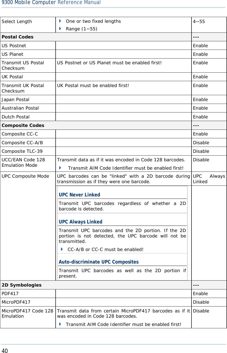
![41 Appendix III 2D Scan Engine When applied, the MicroPDF417 barcodes are transmitted with one of these prefixes: The first codeword of MicroPDF417 is 903-907, 912, 914, 915: The original Code ID "]L3" will be changed to "]C1". The first codeword of MicroPDF417 is 908 or 909: The original Code ID "]L4" will be changed to "]C2". The first codeword of MicroPDF417 is 910 or 911: The original Code ID "]L5" will be changed to "]C0". Data Matrix Enable Maxicode Enable QR Code Enable 2D Symbologies - Macro PDF --- Macro PDF is a special feature for concatenating multiple PDF barcodes into one file, known as Macro PDF417 or Macro MicroPDF417. Transmit/Decode Mode Decide how to handle Macro PDF decoding. Buffer All Symbols / Transmit Macro PDF When Complete Transmit all decoded data from an entire Macro PDF sequence only when the entire sequence is scanned and decoded. If the decoded data exceeds the limit of 50 symbols, no transmission because the entire sequence was not scanned! Transmit Any Symbol in Set / No Particular Order Transmit data from each Macro PDF symbol as decoded, regardless of the sequence. Passthrough All Symbols Transmit and decode all Macro PDF symbols and perform no processing. In this mode, the host is responsible for detecting and parsing the Macro PDF sequences. Passthrough All Symbols ESC Characters When enabled, it uses the backslash "\" as an Escape character for systems that can process transmissions containing special data sequences. It will format special data according to the Global Label Identifier (GLI) protocol, which only affects the data portion of a Macro PDF symbol transmission. The Control Header, if enabled, is always sent with GLI formatting. None](https://usermanual.wiki/CipherLab/9300.User-Manual/User-Guide-1158411-Page-49.png)
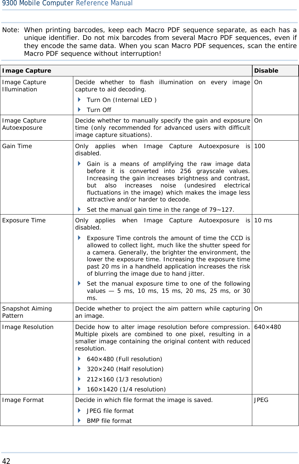
![43 Appendix III 2D Scan Engine Optimized for JPEG Quality Decide whether JPEG images are optimized for quality. Cancel the check box so that JPEG images are optimized for size. Enable Select JPEG Quality Set a value from 5 to 100, where “100” represents the highest quality image. 65 Select JPEG Size Set a value from 5 to 150, which represents the file size in multiples of 1024 bytes (1K). For example, setting this value to 8 permits the file size to be as large as 8192 bytes. 40 Bits per Pixel Select the number of significant bits per pixel (BPP) to use when capturing an image. 1 bit per pixel (for black and white images) 4 BPP (to assign 1 of 16 levels of grey to each pixel) 8 BPP (to assign 1 of 256 levels of grey to each pixel) 8 Note: (1) For JPEG files, these BPP settings are ignored for it always uses 8 bits per pixel! (2) When the image capture feature is enabled, press the [SCAN] button and it will capture an image instead of reading a barcode. Miscellaneous Options --- Transmit Code ID Decide whether to include AIM Code ID in the beginning of data. Each AIM Code ID contains the three-character string “]cm” – ] = Flag Character (ASCII 93) c = Code Character (see below) m = Modifier Character (see below) Disable](https://usermanual.wiki/CipherLab/9300.User-Manual/User-Guide-1158411-Page-51.png)

![45 Appendix III 2D Scan Engine 0 Modulo 10 check digit verified and transmitted. MSI 1 Modulo 10 check digit verified but not transmitted. Discrete 25 0 Always transmit 0. 0 Standard data packet in full EAN country code format, which is 13 digits for UPC-A and UPC-E (not including supplemental data). 3 Standard data packet with two-digit or five-digit supplemental data. 4 EAN-8 data packet. UPC/EAN A UPC-A with Addon 2 barcode, 012345678905-10, is transmitted to the host as a 18-character string, ]E3001234567890510. Bookland EAN 0 Always transmit 0. Trioptic Code 39 0 Always transmit 0. 0 Single check digit (has been verified.) 1 Two check digits (has been verified.) Code 11 3 Checksum has been verified but not transmitted. 0 Always transmit 0. RSS Family RSS-14 and RSS Limited will be transmitted with an Application Identifier “01”. For example, an RSS-14 barcode, 100123456788902, is transmitted as ]e001100123456788902. Note: In UCC/EAN-128 emulation mode, RSS is transmitted using Code 128 rules (i.e. “]C1”). Native mode transmission 0 Standard data packet 1 Data packet containing the data following an encoded symbol separator character. 2 Data packet containing the data following an escape mechanism character. The data packet does not support the ECI protocol. 3 Data packet containing the data following an escape mechanism character. The data packet supports the ECI protocol. UCC/EAN-128 emulation EAN.UCC Composites (RSS, UCC/EAN-128, 2D portion of UPC composite) 1 Data packet is a UCC/EAN-128 barcode (i.e. data is preceded with “]JC1”). Note: UPC portion of composite is transmitted using UPC rules. PDF417, Micro PDF417 0 Scan engine is set to conform to protocol defined in 1994 PDF417 symbology specifications. When this option is transmitted, the receiver cannot reliably determine whether ECIs have been invoked or whether data byte 92DEC has been doubled in](https://usermanual.wiki/CipherLab/9300.User-Manual/User-Guide-1158411-Page-53.png)
![46 9300 Mobile Computer Reference Manual transmission. 1 Scan engine is set to follow the ECI protocol (Extended Channel Interpretation). All data characters 92DEC are doubled. 2 Scan engine is set for Basic Channel operation (no escape character transmission protocol). Data characters 92DEC are not doubled. When decoders are set to this mode, unbuffered Macro symbols and symbols requiring the decoder to convey ECI escape sequences cannot be transmitted. 3 The barcode contains a UCC/EAN-128 symbol, and the first codeword is 903-907, 912, 914, 915. 4 The barcode contains a UCC/EAN-128 symbol, and the first codeword is in the range 908-909. 5 The barcode contains a UCC/EAN-128 symbol, and the first codeword is in the range 910-911. A PDF417 barcode, ABCD, with no transmission protocol enabled, is transmitted as ]L2ABCD. 0 ECC 000-140, not supported. 1 ECC 200. 2 ECC 200, FNC1 in first or fifth position. 3 ECC 200, FNC1 in second or sixth position. 4 ECC 200, ECI protocol implemented. 5 ECC 200, FNC1 in first or fifth position, ECI protocol implemented. Data Matrix 6 ECC 200, FNC1 in second or sixth position, ECI protocol implemented. 0 Mode 4 or 5 1 Mode 2 or 3 2 Mode 4 or 5, ECI protocol implemented. Maxicode 3 Mode 2 or 3, ECI protocol implemented in secondary message. 0 Model 1 1 Model 2, ECI protocol not implemented. 2 Model 2, ECI protocol implemented. 3 Model 2, ECI protocol not implemented, FNC1 implied in first position. 4 Model 2, ECI protocol implemented, FNC1 implied in first position. 5 Model 2, ECI protocol not implemented, FNC1 implied in second position. QR Code 6 Model 2, ECI protocol implemented, FNC1 implied in second position](https://usermanual.wiki/CipherLab/9300.User-Manual/User-Guide-1158411-Page-54.png)