CipherLab 9300 Terminal User Manual 9300 Mobile Computer
CipherLab Co., Ltd. Terminal 9300 Mobile Computer
Contents
- 1. User Manual
- 2. User Manual
User Manual
Windows CE Mobile Compute
r
9300
Version 0.09

Copyright © 2009 CIPHERLAB CO., LTD.
All rights reserved
The software contains proprietary information of CIPHERLAB CO., LTD.; it is provided
under a license agreement containing restrictions on use and disclosure and is also
protected by copyright law. Reverse engineering of the software is prohibited.
Due to continued product development this information may change without notice. The
information and intellectual property contained herein is confidential between CIPHERLAB
and the client and remains the exclusive property of CIPHERLAB CO., LTD. If you find
any problems in the documentation, please report them to us in writing. CIPHERLAB
does not warrant that this document is error-free.
No part of this publication may be reproduced, stored in a retrieval system, or
transmitted in any form or by any means, electronic, mechanical, photocopying,
recording or otherwise without the prior written permission of CIPHERLAB CO., LTD.
For product consultancy and technical support, please contact your local sales
representative. Also, you may visit our web site for more information.
The CipherLab logo is a registered trademark of CIPHERLAB CO., LTD.
Microsoft, Windows, and the Windows logo are registered trademarks of Microsoft
Corporation in the United States and/or other countries.
Bluetooth is a trademark of Bluetooth SIG, Inc., U.S.A.
Other product names mentioned in this manual may be trademarks or registered
trademarks of their respective companies and are hereby acknowledged.
The editorial use of these names is for identification as well as to the benefit of the
owners, with no intention of infringement.
CIPHERLAB CO., LTD.
Website: http://www.cipherlab.com

IMPORTANT NOTICES
FOR USA
This equipment has been tested and found to comply with the limits for a Class B digital
device, pursuant to Part 15 of the FCC Rules. These limits are designed to provide
reasonable protection against harmful interference in a residential installation. This
equipment generates, uses and can radiate radio frequency energy and, if not installed
and used in accordance with the instructions, may cause harmful interference to radio
communications. However, there is no guarantee that interference will not occur in a
particular installation. If this equipment does cause harmful interference to radio or
television reception, which can be determined by turning the equipment off and on, the
user is encouraged to try to correct the interference by one or more of the following
measures:
Reorient or relocate the receiving antenna.
Increase the separation between the equipment and receiver.
Connect the equipment into an outlet on a circuit different from that to which the
receiver is connected.
Consult the dealer or an experienced radio/TV technician for help.
This device complies with Part 15 of the FCC Rules. Operation is subject to the following
two conditions: (1) This device may not cause harmful interference, and (2) this device
must accept any interference received, including interference that may cause undesired
operation.
FOR CANADA
This digital apparatus does not exceed the Class B limits for radio noise emissions from
digital apparatus as set out in the interference-causing equipment standard entitled
"Digital Apparatus," ICES-003 of Industry Canada.
This device complies with Part 15 of the FCC Rules. Operation is subject to the following
two conditions: (1) This device may not cause harmful interference, and (2) this device
must accept any interference received, including interference that may cause undesired
operation.
Cet appareil numerique respecte les limites de bruits radioelectriques applicables aux
appareils numeriques de Classe B prescrites dans la norme sur le material brouilleur:
"Appareils Numeriques," NMB-003 edictee par l'Industrie.
FOR HAND-HELD PRODUCT WITH RF FUNCTIONS
This equipment complies with FCC radiation exposure limits set forth for an uncontrolled
environment. This equipment should be installed and operated with minimum distance 20
cm between the radiator & your body. It only operated in hand-held used.

If you only transfer data to Host by WLAN/Bluetooth, please keep the minimum distance
20 cm between machine & your body.
FOR PRODUCT WITH LASER
Per FDA and IEC standards, the scan engines described in this manual are not given a
laser classification. However, the following precautions should be observed:
CAUTION
This laser component emits FDA / IEC Class 2 laser light at the exit port. Do not
stare into beam.
SAFETY PRECAUTIONS
RISK OF EXPLOSION IF BATTERY IS REPLACED BY AN INCORRECT TYPE.
DISPOSE OF USED BATTERIES ACCORDING TO THE INSTRUCTIONS.
The maximum level of Specific Absorption Rate (SAR) measured is 0.211 W/kg.
The use of any batteries or charging devices, which are not originally sold or
manufactured by CipherLab, will void your warranty and may cause damage to
human body or the product itself.
DO NOT disassemble, incinerate or short circuit the battery.
DO NOT expose the scanner or the battery to any flammable sources.
For green-environment issue, it's important that batteries should be recycled in a
proper way.
Under no circumstances, internal components are self-serviceable.
The charging and communication cradle uses an AC power adaptor. A socket outlet
shall be installed near the equipment and shall be easily accessible. Make sure there
is stable power supply for the mobile computer or its peripherals to operate properly.
CARE & MAINTENANCE
This mobile computer is intended for industrial use. The mobile computer is rated IP
54, however, it may do damage to the mobile computer when being exposed to
extreme temperatures or soaked wet.
When the body of the mobile computer gets dirty, use a clean and wet cloth to wipe
off the dust. DO NOT use/mix any bleach or cleaner. Always keep the LCD dry.
For a liquid crystal display (LCD) or touch screen, use a clean, non-abrasive, lint-free
cloth to wipe dust off the screen. DO NOT use any pointed or sharp object to move
against the surface.
If you want to put away the mobile computer for a period of time, download the
collected data to a host computer, and then take out the battery pack. Store the
mobile computer and battery pack separately.
When the mobile computer resumes its work, the main and backup batteries will take
a certain time to become fully charged.
If you shall find the mobile computer malfunctioning, write down the specific scenario
and consult your local sales representative.

RELEASE NOTES
Version Date Notes
1.00 Initial release
0.09 Jun. 16, 2009 First draft
FCC Caution: Any changes or modifications not expressly approved by the party
responsible for compliance could void the user's authority to operate this equipment.
This device and its antenna(s) must not be co-located or operating in conjunction with any
other antenna or transmitter.

CONTENTS
IMPORTANT NOTICES ................................................................................- 3 -
For USA..............................................................................................- 3 -
For Canada..........................................................................................- 3 -
For Hand-held Product with RF Functions.....................................................- 3 -
For Product with Laser ...........................................................................- 4 -
Safety Precautions.................................................................................- 4 -
Care & Maintenance...............................................................................- 4 -
RELEASE NOTES.......................................................................................- 5 -
INTRODUCTION........................................................................................... 1
Getting Familiarized with 9300 .....................................................................2
Installing the Hand Strap .........................................................................3
Charging the Battery ..............................................................................4
Features.................................................................................................5
Inside the Package ....................................................................................5
Accessories .............................................................................................6
USING 9300 MOBILE COMPUTER...................................................................... 7
1.1 Battery..............................................................................................7
1.1.1 Inserting the Battery .......................................................................7
1.1.2 Charging the Battery .......................................................................9
1.1.3 Understanding the Battery Icons .........................................................9
1.1.4 Power Management....................................................................... 10
1.2 Memory........................................................................................... 11
1.2.1 Caution of Data Loss...................................................................... 11
1.2.2 Inserting the SD Card..................................................................... 11
1.3 Keypad............................................................................................ 12
1.3.1 Keypad Settings ........................................................................... 12
1.3.2 29-key Keypad............................................................................. 13
1.3.3 43-key Keypad............................................................................. 15
1.3.4 Function Key............................................................................... 16
1.3.5 Programmable Keys....................................................................... 16
1.4 Touch Screen .................................................................................... 17
1.4.1 Adjusting the Backlight .................................................................. 17
1.4.2 Re-calibrating the Screen................................................................ 18
1.5 Notifications ..................................................................................... 19
1.5.1 Status LED.................................................................................. 19
1.5.2 Audio........................................................................................ 19
1.5.3 Vibrator..................................................................................... 20
1.6 Data Capture .................................................................................... 20
1.6.1 Barcode & RFID Reader .................................................................. 20

9300 Mobile Compute
r
Reference Manual
SPECIFICATIONS.........................................................................................21
Platform, Processor & Memory.................................................................... 21
Communications & Data Capture ................................................................. 21
Electrical Characteristics........................................................................... 22
Physical Characteristics ............................................................................ 22
Environmental Characteristics..................................................................... 23
Programming Support............................................................................... 23
Accessories ........................................................................................... 24
SCAN ENGINE SETTINGS ...............................................................................25
Symbologies Supported ............................................................................. 25
RFID Tags Supported ................................................................................ 27
CCD/LASER SCAN ENGINE .............................................................................29
Reader Settings Table .............................................................................. 29
Symbology Settings Table .......................................................................... 30
2D SCAN ENGINE........................................................................................35
Reader Settings Table .............................................................................. 35
Symbology Settings Table .......................................................................... 36
AIM Code ID – Code Characters................................................................. 44
AIM Code ID – Modifier Characters............................................................. 44

1
INTRODUCTION
9300 Mobile Computer, running Windows CE 6.0 in palm size, is our first product line of
rugged PDA-style Mobile Computer. Light-weight, streamlined and ergonomic, it adds
even more powerful and handy tools to delivering the flexibility in customization.
Specifically designed to work as an industrial PDA, 9300 Mobile Computer provides rich
options of data collection, voice and data communications, long-lasting working hours,
and so on. Its large color transflective TFT display guarantees ease in reading in all
lighting conditions. Integrated with Bluetooth and 802.11b/g technologies, you may
choose to add the GSM/GPRS module to gain greater speeds and optimal mobility.
This manual serves to guide you through how to install, configure, and operate the
mobile computer. The Care & Maintenance section is specifically prepared for those who
are in charge of taking care of the mobile computer.
We recommend you to keep one copy of the manual at hand for quick reference or
maintenance purposes. To avoid any improper disposal or operation, please read the
manual thoroughly before use.
Thank you for choosing CipherLab products!

2
9300 Mobile Compute
r
Reference Manual
GETTING FAMILIARIZED WITH 9300
Figure 1: Overview

3
Introduction
INSTALLING THE HAND STRAP
The hand strap is ideal for one-handed operation, which requires safe and convenient
hold of the mobile computer.
Warning: Always make sure the hand strap is well hooked and screwed to the back
of the mobile computer before use.
When the hand strap is desired, install it to the mobile computer by following these
steps:
1) Place the mobile computer face down on a flat and clean surface.
2) Screw one end of the hand strap to the back of the mobile computer.
3) Insert and hook the other end of the hand strap to the bottom of the mobile
computer.
4) Make sure the hand strap is securely attached to the mobile computer.
5) Adjust the length of the hand strap to suit your handbreadth.
Figure 2: Installing the Hand Strap

4
9300 Mobile Compute
r
Reference Manual
CHARGING THE BATTERY
You can use a cradle or charger to charge the Mobile Computer and/or its battery. Below
are the 4-Slot Battery Charger and 4-Slot Charging Cradle for 9300. The 4-Slot Battery
Charger can be mounted on table or wall. Drill two holes (centers spaced 105 millimeters
apart), secure the two supplied screws, and mount the charger by sliding over screws.
Warning: It is recommended that the charging devices be operated at room
temperature (18°C to 25°C) for optimal performance. The charging devices
will not charge the battery when the temperature exceeds 40°C.
1) Seat batteries with contacts facing to back in the 4-Slo Battery Charger (top), or seat
the mobile computers in the 4-Slot Charging Cradle (bottom).
2) Connect the power supply cord to the power receptacle on the charger or cradle.
3) Connect the other end of the power cord to a suitable power outlet.
4) Press the power switch on, and the charger’s LED or the Power LED on the cradle will
be blue.
5) For the 4-Slot Battery Charger, the LED will be red while charging, and will be green
when fully charged.
For the 4-Slot Charging Cradle, the LED on each of the mobile computers will be red
while charging, and will be green when fully charged.
Figure 3: 4-Slot Battery Charger

5
Introduction
FEATURES
Ergonomic design - ruggedized yet streamlined, with hand strap for secure hold.
Built tough to survive drop test and sealed against moisture/dust to industrial
standard IP 64.
Microsoft Windows CE 6.0 operating system, 624 MHz Marvell PXA310 processor
512 MB non-volatile NAND flash memory to store OS and software programs
(part of the free space is used as a storage card called DiskOnChip)
256 MB on-board DDR SDRAM to store and run programs, as well as store program
data
One SD expansion slot for memory card
Dual mode support - One scan engine (integrated barcode scanner/imager) plus one
RFID reader
Ambidextrous side triggers
Total wireless solution - connectivity includes Bluetooth, 802.11b/g and
GSM/EDGE/GPRS.
A 2.8" color transflective TFT display delivers excellent visibility in all lighting
conditions.
Programmable feedback includes buzzer, speaker and vibrator.
Built-in power tools include Reader Configuration Utility, Backup Utility, etc.
Terminal Emulation client for VT100/220 and IBM 5250 enables a quick link to any
backend database.
Application Generator (AG*.exe for desktop PC) enables easy customization of data
collection applications.
Programming support includes Reader DLL and System APIs.
Accessories and peripherals include pistol grip, international AC charging cradle, etc.
INSIDE THE PACKAGE
The following items are included in the package. Save the box and packaging material for
future use in case you need to store or ship the mobile computer.
9300 Mobile Computer
Rechargeable Li-ion battery pack
Stylus
Hand Strap
Software & Manual CD
Note: For battery charging, you will need to purchase a charging cradle separately.

6
9300 Mobile Compute
r
Reference Manual
ACCESSORIES
Rich choices of optional accessories are available for you to enhance the total
performance of the mobile computer.
Protective Cover
SD Memory Card
Spare rechargeable Li-ion battery, standard or high capacity pack
4-slot Battery Charger
Charging & Communication Cradle

Chapter 1
USING 9300 MOBILE COMPUTER
This chapter explains the features and usage of 9300 Mobile Computer.
IN THIS CHAPTER
1.1 Battery....................................................................... 7
1.2 Memory.................................................................... 11
1.4 Touch Screen............................................................ 17
1.5 Notifications.............................................................. 19
1.6 Data Capture ............................................................ 20
1.1 BATTERY
Main Battery
9300 Mobile Computer is powered by a rechargeable 3.7 V/2700 mAh Li-ion battery
pack, and it takes approximately 4 hours to fully charge it. However, the charging
time may vary by working condition. During normal operation, the mobile computer
can work for up to 10 hours.
Backup Battery
The backup battery on the main board takes charge when the main battery is
removed or drained out. When fully charged, the 3.6 V/15 mAh rechargeable Lithium
button cell helps retain data in SRAM and maintain the system running in suspend
mode for at least 20 hours without the main battery. In the meantime, you have to
replace the main battery as soon as possible.
1.1.1 INSERTING THE BATTERY
When you first receive the package, the rechargeable functionality of the backup battery
is turned off. It is controlled by a DIP switch inside the battery compartment as shown
below.
For shipping and storage purposes, save the mobile computer and the main battery in
separate packages, and adjust the DIP switch to the OFF position (bottom). This will keep
both batteries in good condition for future use.
Note: Any improper handling may reduce the battery life.
1) Remove the hand strap.
2) Hold the mobile computer still. Press the battery cover latch and slide it to unlock the
battery cover.
3) Remove the battery cover.
7

8
9300 Mobile Compute
r
Reference Manual
4) Insert the battery pack into the battery compartment at a proper angle (30°~45°) so
that the metal contacts on the battery are met with the charging contacts inside the
compartment. Make sure that the battery is snugly fit into the compartment.
5) Put the battery cover back onto the mobile computer until it clicks into place.
6) If the battery is charged, the mobile computer turns on.
If the mobile computer does not turn on, charge the battery.
Note: For a new battery, make sure it is fully charged before use. Always prepare a
spare battery pack, especially when you are on the road.
Figure 4: Installing the Main Battery

9
Specifications
1.1.2 CHARGING THE BATTERY
The main and backup batteries may not be charged to full for shipment. When you first
receive the package, you will need to charge batteries to full before using the mobile
computer.
Note: To charge the batteries to full, it requires approximately 8 hours for the first time.
After the initial charging, it takes only 4 hours to charge the batteries to full.
Because the internal backup battery is constantly charged from the main battery, the
initial charging requires inserting the battery pack to the mobile computer and then
seating the mobile computer in the cradle for charging. This will have both the main and
backup batteries charged at the same time. To charge the backup battery, make sure
that you slide the DIP switch inside the battery compartment to the ON position.
Note: For a new battery, make sure it is fully charged before use. Always prepare a
spare battery pack, especially when you are on the road.
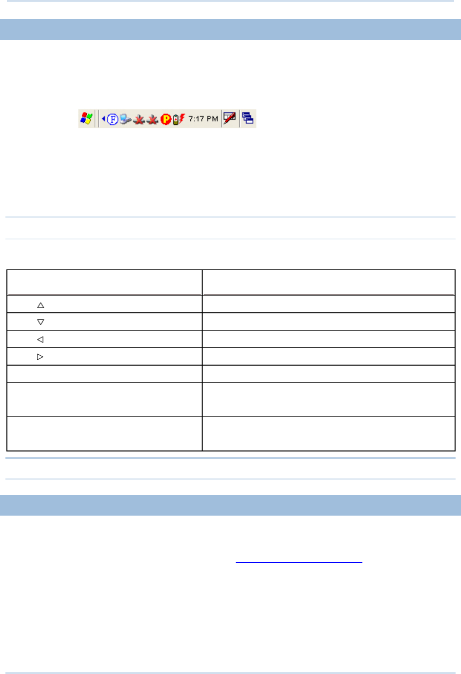
1.1.3 UNDERSTANDING THE BATTERY ICONS
The battery pack is the only power source for the mobile computer to work. It also
charges the backup battery on the main board so that the data stored in SRAM can be
retained properly. Therefore, when the main battery charge goes low, you need to
replace the battery pack with a charged one or charge it as soon as possible. Most of all,
always save data before it is too late; you should backup important data on a regular
basis.
Double-tap a battery icon so that you can quickly access the [Power Properties] dialog
box.
Battery Status Icons Description
Battery charge remaining in the main battery –
The more bars, the more
power in the main battery.
Main battery is ready for charging.
Main battery charge becomes low and needs charging.
Main battery charge becomes very low and needs charging immediately.
Warning: Data loss may occur with SRAM during low battery condition. Always save
data before running out of power or keep a fresh battery for replacement.

10
9300 Mobile Compute
r
Reference Manual
1.1.4 POWER MANAGEMENT
For any portable device, power management is a critical issue especially when you are on
the road. Below are some tips to help you save battery power.
Warning: Using backlight, wireless connectivity, and peripherals while on battery
power will substantially reduce battery power.
To speed up charging the mobile computer, turn off the mobile computer and seat it
in the cradle.
Bring a second battery pack on the road.
Stop wireless connectivity, Bluetooth, 802.11b/g or GSM/GPRS that is not in use.
Go to Start > Settings > Control Panel and double-tap the Display icon. Refer to
1.4.1 Adjusting the Backlight.
Go to Start > Settings > Control Panel and double-tap the Power icon. (below)
1. In the Battery tab (left below), you can always monitor the charging status.
2. Tap the Schemes tab. (right above)
3. Select the desired power scheme and options for suspending operation when not
in use. The system can be set to three different states to conserve power:
User Idle state
System Idle state
Suspend state
The time choices represent the amount of time that must pass before the system
will switch to the next power conservation state.

11
Specifications
1.2 MEMORY
Read-only Memory (ROM)
512 megabytes flash memory for storing OS (Windows CE 6.0) and custom
application programs. Yet a portion of the memory is referred to as DiskOnChip,
which can store data and programs that you wish to retain even after hardware reset.
Random-access Memory (RAM)
256 megabytes SDRAM for storing and running programs, as well as storing program
data. Its contents will be retained by the backup battery.
Expansion Slot
The mobile computer is equipped with one SD card slot, which is user accessible. You
may upgrade memory by inserting an optional SD memory card.
1.2.1 CAUTION OF DATA LOSS
When the main battery is removed or drained, the backup battery on the main board is
to retain the contents of SRAM and maintain the OS in suspend mode for at least 20
hours, on condition that the backup battery has already been fully charged.
If you want to put away the mobile computer for a couple of days, you should be aware
that data loss occurs when both the main and backup batteries discharge completely.
Therefore, it is necessary to backup data and files before putting away the mobile
computer!
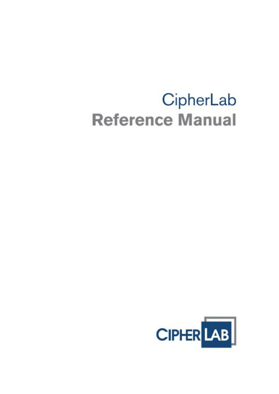
1.2.2 INSERTING THE SD CARD
If you wish to expand memory, follow these steps to insert a memory card into the SD
card slot:
1) Press for the mobile computer to enter suspend mode.
2) Place the mobile computer face down on a flat and clean surface.
3) Remove the side plate by unscrewing the two screws (on the right side when you
place the mobile computer face down) as shown below.
4) Insert the SD card properly.
12
9300 Mobile Compute
r
Reference Manual
5) Replace the side plate and tighten the screws.
Warning: Make sure the mobile computer is set to Suspend mode; otherwise, it may
cause damage to the mobile computer.
Figure 5: Inserting the SD Card
REMOVING THE SD CARD
If you wish to remove the SD card, simply push the card after removing the side plate.
The SD card will be rejected automatically.
1.3 KEYPAD
Silicon rubber has been chosen for their durability and prompt feedback.
Note: Functionality of keys is application-dependent.
1.3.1 KEYPAD SETTINGS
Press [FN] first, and then [0].
The LED backlight of keypad is turned off by default. It can be toggled ON/OFF by the
key combination: [FN] + [0]. It is suggested to turn on the keypad backlight while
working in a dark area; however, using backlight while on battery power will
substantially reduce battery power.
Go to Start > Settings > Control Panel and double-tap the Keyboard icon.
The Character Repeat functionality is enabled by default. You may cancel the check
box to disable it. When enabled, tap, hold, and drag the slider for a desired Repeat
Delay and Repeat Rate.

13
Specifications
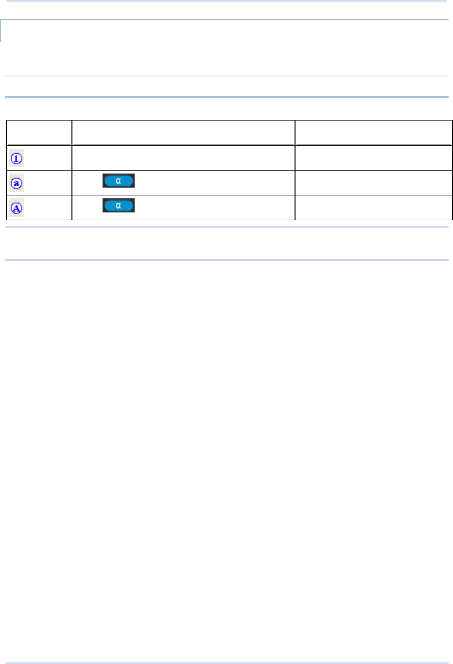
1.3.2 29-KEY KEYPAD
The 29-key keypad includes alphanumeric, navigation, function keys, and so on. This
keypad is set to numeric mode by default.
Q
V
G
A
Screen + 29-key
Figure 6: 29-key Layout
14
9300 Mobile Compute
r
Reference Manual
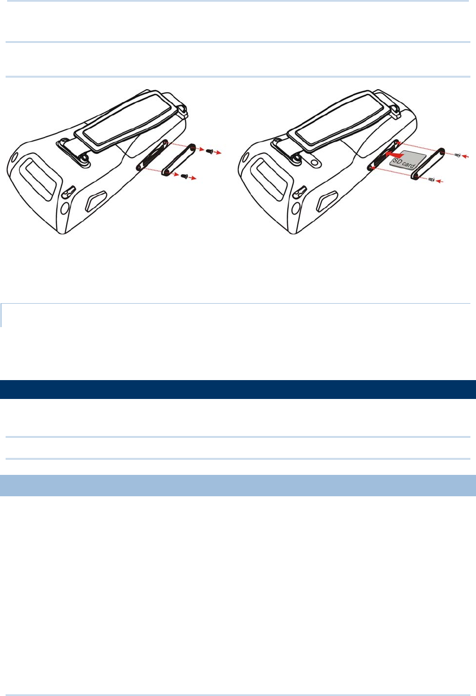
ALPHA KEY
This alphanumeric keypad is set to numeric mode by default. The Alpha key serves as a toggle
among numeric, alpha (lower-case alphabetic), and ALPHA (upper-case alphabetic) input modes.
Note: It is not necessary to hold down the [Alpha] key.
The alpha icon will appear on the status bar in a sequence as shown below.
Status Icon Alpha Key Input Mode
N/A Numbers
Press one time Small letters
Press two times Capital letters
Note: If you are using the software keypad via SIP, tap CAP (Caps Lock) to toggle
between upper case and lower case alphabetic modes.
15
Specifications
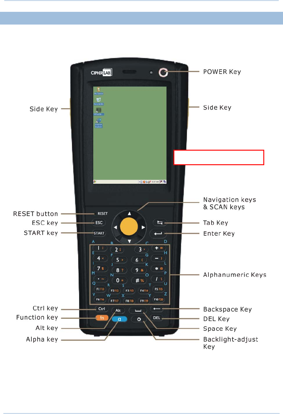
1.3.3 43-KEY KEYPAD
The 43-key keypad includes numeric, alphabetic, function and other modifier keys, as
well as keys for navigation and assorted characters.
Q
VGA Screen + 43-key
Figure 7: 43-key Layout
16
9300 Mobile Compute
r
Reference Manual
1.3.4 FUNCTION KEY
The [FN] (function) key serves as a modifier key, and the functionality of each key
combination is application-dependent.
1) To enable this modifier key, press [FN] on the keypad. A circular icon of the letter "F"
will appear on the status bar. This modifier key is hold down as long as the icon is
displayed.
2) Now press another key to get the value of key combination (say, press [1] to get the
value of F1). The icon will go off now.
3) To get the value of another key combination modified by the [FN] key, repeat the
above steps.
4) To abort the key modification, press [FN] again, and the icon will go off.
Note: It is not necessary to hold down the [FN] key.
Below is a list of the factory setting for a variety of key combinations.
Key Combination Action
[FN], Move text up one screenful (Page Up)
[FN], Move text down one screenful (Page Down)
[FN], Move to the beginning of screen or document (Home)
[FN], Move to the end of screen or document (End)
[FN], [0] Toggle ON/OFF the backlight of keypad only
([FN], [*@-] for 28-key)
([FN], [.$] for 59-key)
T
urn ON the backlight of LCD and decrease its
luminosity
([FN], [.#$] for 28-key)
([FN], [- ;] for 59-key)
Turn ON the backlight of LCD and increase its
luminosity
Note: Press the [FN] key first, and then press the second key for a specific function.
1.3.5 PROGRAMMABLE KEYS
Depending on the keypad layout, a number of keys are user-definable, such as the
programmable keys. They can be re-defined as another key or to serve as a shortcut key
for launching a specific program. Refer to the Button Assignment Utility.

17
Specifications
Programmable Keys Other User-Definable Keys
P1, P2 (28-key) SCAN key and four side triggers on each side of the touch screen
P1, P2, P3 and P4 (59-key) Four side triggers on each side of the touch screen
1.4 TOUCH SCREEN
The mobile computer comes with a 2.8" TFT graphic LCD, 320 by 240 pixels resolution
(QVGA). The LED backlight of screen, which helps ease reading under dim environments,
can be controlled manually and automatically.
Warning: Using backlight while on battery power will substantially reduce battery
power. It is suggested to dim the backlight while working in a well-lit area
or automatically turn off the mobile computer when not in use.
1.4.1 ADJUSTING THE BACKLIGHT
The LED backlight of the screen can be turned on and adjusted decreasingly or
increasingly by the following key combinations. Keep pressing the key combination until
the luminosity is decreased or increased to a desired level.
Key Combination Action
, ([Backlight], [DOWN] for 29-key)
, ([[Backlight], [DOWN] for 43-key)
T
urn ON the backlight of LCD and decrease its
luminosity
, ([[Backlight], [UP] for 29-key)
, ([[Backlight], [UP] for 43-key)
T
urn ON the backlight of LCD and increase its
luminosity
Note: Press the [FN] key first, and then press the second key for adjustment.
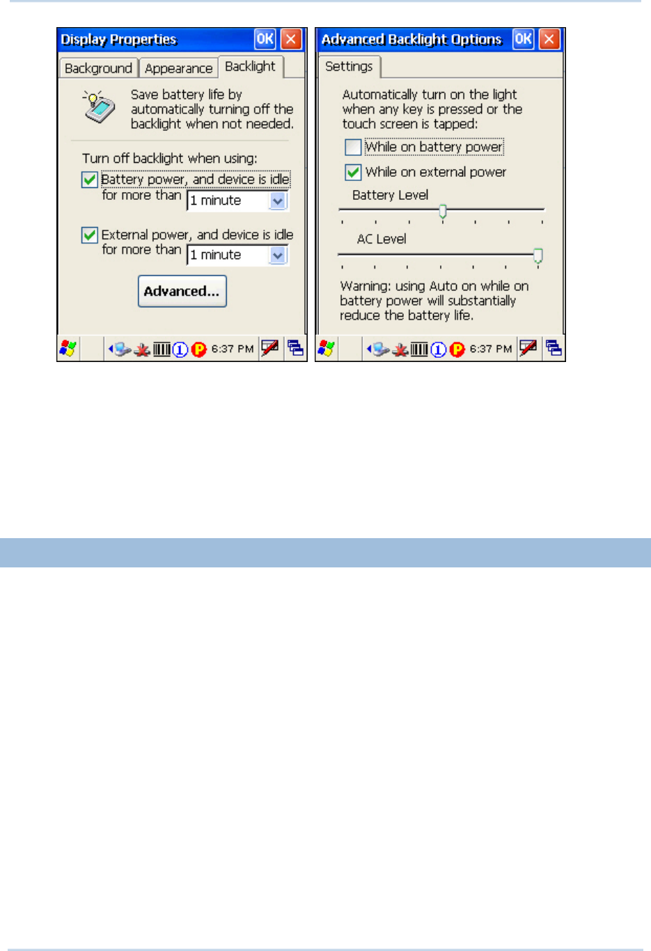
Go to Start > Settings > Control Panel and double-tap the Display icon.
1. Tap the Backlight tab. (left below)
18
9300 Mobile Compute
r
Reference Manual
2. Select one or both of the check boxes to automatically turn off the LCD backlight
when using batteries or external power. From the appropriate list, select the
amount of time the device should be idle before the backlight is turned off.
3. Tap the [Advanced] button.
4. In the Settings tab (right above), you can select the luminosity of backlight when
it is set to be automatically turned on by pressing any key or tapping the screen.
Tap, hold, and drag the slider for AC and battery powered respectively. For more
luminosity, move the slider to the right.
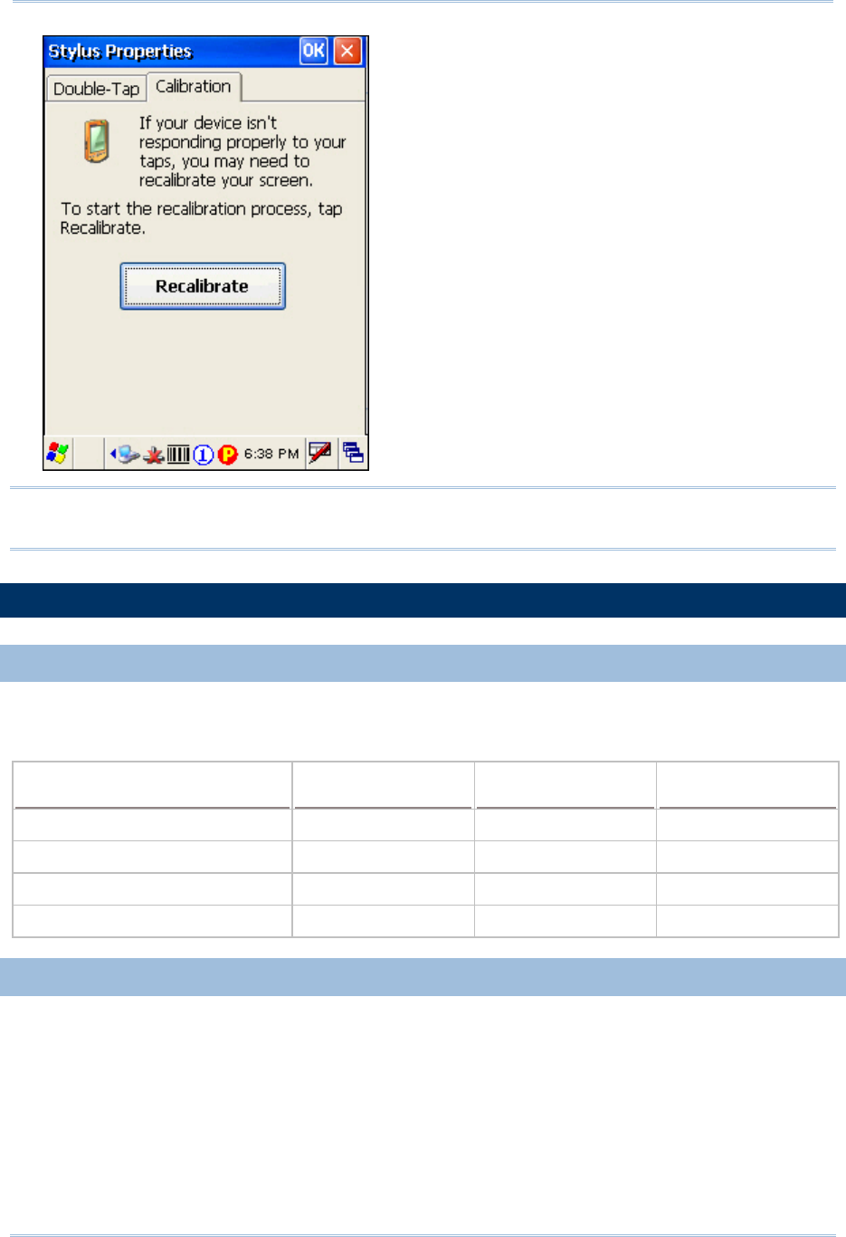
1.4.2 RE-CALIBRATING THE SCREEN
This LCD is also a touch screen that can be calibrated through screen alignment.
Go to Start > Settings > Control Panel and double-tap the Stylus icon.
Tap the Calibration tab, and then tap the [Recalibrate] button.
19
Specifications
Warning: DO NOT use any pointed or sharp objects to move against the surface of
the screen.
1.5 NOTIFICATIONS
1.5.1 STATUS LED
The tri-color LED on top is used to provide information on the charging status or wireless
power status. The green LED is also used for "Good Read" while collecting data.
Tasks Green LED Red LED Blue
Charging 9300 --- On ---
Charging done On --- ---
Good Read On --- ---
Bluetooth enabled --- --- On
1.5.2 AUDIO
Buzzer
The mobile computer has a buzzer on the back. It can be programmed for status
feedback. Its frequency and duration are software programmable.
Speaker
The mobile computer is integrated with a mono speaker, which can be used for
playing sounds applied to events in Windows and programs, as well as playing audio
files such as .WAV files. In addition, it can be programmed for status feedback.

20
9300 Mobile Compute
r
Reference Manual
Headset
A headset jack is provided, which is a 2.5 mm DIA stereo earphone jack with
microphone input. Bluetooth headset is also supported.
1.5.3 VIBRATOR
The mobile computer is integrated with a vibrator, which is software programmable for
feedback. This can be helpful when working in noisy environments.
1.6 DATA CAPTURE
1.6.1 BARCODE & RFID READER
A wide variety of scan engines is available for delivering flexibility to meet different
requirements. Depending on the scan engine integrated, the mobile computer is capable
of scanning barcodes of a number of symbologies that are enabled by default while
running 93ReaderConfig.exe. If you need to scan barcodes that are encoded in a
different symbology, enable the symbology first. Refer to Appendixes for details on scan
engine settings.
Appendix I - Scan Engine Settings lists the symbologies and RFID tags supported.
Appendix II - CCD/Laser Scan Engine provides information on the reader settings as
well as symbology settings for the CCD or Laser scan engine.
Appendix III - 2D Scan Engine provides information on the reader settings as well as
symbology settings for the 2D scan engine.
Note: The mobile computer allows the co-existence of one integrated scan engine and
the RFID reader.

21
Specifications
SPECIFICATIONS
PLATFORM, PROCESSOR & MEMORY
Operating System
Microsoft Windows CE 6.0
CPU
Marvell PXA310 at 624 MHz
Memory
ROM 512 MB non-volatile NAND flash memory
RAM 256 MB on-board DDR SDRAM memory
Expansion Slot One SD card slot for inserting memory card, optional
COMMUNICATIONS & DATA CAPTURE
Communications
USB 1.1 Specification
Host port (type-A) / Device port (type-B)
USB via Cradle
USB Client 2.0
WPAN Built-in module for Bluetooth Class 2 connectivity
WLAN Built-in module for 802.11b/g networking
RS232 Support baud rate 9600, 19200, 38400, 57600, 115200, 230k, 640k, and
921k.
Data & Image Capture
Barcode Reader Ordering options include
1D SE 955 Standard Laser
2D Imager

22
9300 Mobile Compute
r
Reference Manual
ELECTRICAL CHARACTERISTICS
Batteries
Main Battery Pack Rechargeable Li-ion battery – 3.7 V, 2700 mAh
Backup Battery Rechargeable Lithium battery – 3.6 V, 15 mAh
Data retention for at least 20 hours
Power Adapter
Input AC 100~240 V, 50/60 Hz
Output DC 5 V, 3 A (Charging & Comm. Cradle)
Working Time (Laser, one scan per 5 seconds)
Batch Mode with backlight 10 hours
Wi-Fi Mode with backlight 8 hours
PHYSICAL CHARACTERISTICS
Color Touch Screen Display
Display 2.8” Transflective TFT-LCD, 65536 colors
Resolution QVGA (320 × 240 pixels)
Keypad
Layout 29 keys for alphanumeric layout
Ordering Option – 43-key layout
Backlight White LED backlight for display and keypad
Notifications
Status LED Two dual color LED – Red / Green and Green / Blue
Audio Integrated with one mono speaker and buzzer
Headset jack –
2.5 mm DIA stereo earphone jack with
microphone input
Bluetooth headset supported
Vibrator 0.45G
Enclosures
Materials Plastic and metal
Dimensions 170 mm (L) 70 mm (W) 40 mm (H)
Weight Approx. 350 g (configuration-dependent)

23
Specifications
ENVIRONMENTAL CHARACTERISTICS
Temperature
Operating -10 °C to 50 °C
Storage -20 °C to 60 °C
Humidity
Operating 10% to 90%, non-condensing
Storage 5% to 95%, non-condensing
Resistance
Impact Resistance 1.5 m, 5 drops per 6 sides
Tumble Test 100 cm, 1000 drops
Splash/Dust Resistance IP 54
Electrostatic Discharge ± 15 kV air discharge, ± 8 kV direct discharge
Regulations
EMC Regulations FCC, IC, CE, C-Tick, MIC, BSMI, NCC, TELEC, SRMC
PROGRAMMING SUPPORT
Development Environment & Tools
Integrated Development
Environment Visual Studio 2005
Visual Studio .NET 2003
eMbedded Visual C++ 4.0 SP4
9300 SDK or Windows CE 6.0 Standard SDK Software Development Kit
System API (static and DLL) for system configuration
ReaderDLL for reader configuration
Software & Utilities
Reader Configuration Utility
Terminal Emulation for VT100/220 or IBM 5250
Application Generator
STREAM Wireless Studio
Web Browser
Third-party software –
Wavelink Avalanche Enabler & Telnet Client
MCL Collection - MCL Client

24
9300 Mobile Compute
r
Reference Manual
ACCESSORIES
Accessory Options
SD Memory Card
Protective Cover
Spare rechargeable battery pack, standard or high capacity pack
4-Slot Battery Charger
Charging & Communication Cradle

25
Appendix I
SCAN ENGINE SETTINGS
The Reader Configuration Utility (93ReaderConfig.exe) allows configuring the
following reader types, depending on the module equipped on your mobile computer:
1D CCD scan engine
1D Laser scan engine
2D scan engine
RFID reader
Options of different reader combination are allowed, such as 1D+RFID and 2D+RFID. For
each combination, both readers can be initialized and ready for scanning at the same
time (dual mode operation). For example, if you press the [SCAN] button while running
the 93ReaderConfig utility on the mobile computer, it will read a barcode in position or an
RFID tag in proximity depending on which one comes first.
Note: (1) You cannot have 1D+2D scan engines installed on the mobile computer
because they are both barcode readers!
(2) You can run only one utility or application at a time to control the reader(s).
For example, while running 93ReaderConfig.exe, you should not run Application
Generator, STREAM Wireless Studio, MIRROR Browser, or any other application
that uses ReaderDLL.
SYMBOLOGIES SUPPORTED
Varying by the scan engine installed, the supported symbologies or tag types are listed
below. For details on configuring associated settings, please refer to each Appendix
separately.
CCD, Laser 2D
Codabar 9 9
Code 11 8 9
Code 93 9 9
Composite Code 8 9
MSI 9 9
Plessey 9 8
Postal Codes 8 9
Telepen 9 8
Code 128 Code 128 9 9
EAN-128 9 9

26
9300 Mobile Compute
r
Reference Manual
ISBT-128 8 9
Code 2 of 5 Industrial 25 (i.e. Discrete 25) 9 9
Interleaved 25 9 9
Matrix 25 9 8
Code 3 of 9 Code 39 9 9
Trioptic Code 39 8 9
Italian Pharmacode (i.e. Code 32) 9 9
French Pharmacode 9 8
EAN/UPC EAN-8 9 9
EAN-13 9 9
Bookland EAN (i.e. ISBN) 9 9
UPC-E0 9 9
UPC-E1 8 9
UPC-A 9 9
RSS RSS-14 9 9
RSS Limited 9 9
RSS Expanded 9 9
2D Symbologies PDF417 8 9
MicroPDF417 8 9
Data Matrix 8 9
Maxicode 8 9
QR Code 8 9

27
Appendix I
Scan Engine Settings
RFID TAGS SUPPORTED
The RFID reader supports read/write operations depending on the tags. The supported
labels include ISO 15693, Icode®, Tag-it®, ISO 14443A, and ISO 14443B.
Currently, the performance of many tags has been confirmed, and the results are listed
below for your reference.
Note: You should study the specifications of RFID tags before use.
TI_RFID Module Version 1.0.A UID Only Read Page Write Page
ISO 14443A Mifare Standard 1K 9 --- ---
Mifare Standard 4K 9 --- ---
Mifare Ultralight 9 --- ---
Mifare DESFire 9 --- ---
Mifare S50 9 --- ---
SLE44R35 9 --- ---
SLE66R35 9 --- ---
ISO 14443B SRIX 4K --- --- ---
SR176 --- --- ---
ISO 15693 ICODE SLI 9 9 9
SRF55V02P 9 9 9
SRF55V02S 9 --- ---
SRF55V10P 9 9 9
TI Tag-it HF-I 9 9 9
ST LRI512 9 --- ---
Tag-it® Tag-it 9 9 9
ICODE®
(Phillips) ICODE --- --- ---

28
9300 Mobile Compute
r
Reference Manual

29
Appendix II
CCD/LASER SCAN ENGINE
The tables below list reader settings as well as symbology settings for the CCD or Laser
scan engine.
READER SETTINGS TABLE
CCD/Laser Description Default
Time-out 3 sec.
1~9 (second) for
93ReaderConfig.exe
0~255 (second) for
programming
Set the maximum time for decoding to continue during a scan attempt. It
applies to the following scan modes only –
Aiming mode
Laser mode
Auto Off mode
Auto Power Off mode
Scan Mode Laser mode
Continuous Mode Non-stop scanning
To decode
the same barcode repeatedly, move away the scan beam
and target it at the barcode for each scanning.
Test Mode Non-stop scanning
Capable of decoding the same barcode repeatedly
Repeat Mode Non-stop scanning
Capable of re-transmitting barcode data if triggering within one second
after a successful decoding
Momentary Mode Hold down the scan trigger to start with scanning.
The scanning won't stop until you release the trigger.
Alternate Mode Press the scan trigger to start with scanning.
The scanning won't stop until you press the trigger again.
Aiming Mode Press the scan trigger to aim at a barcode. Within one second, press the
trigger again to decode the barcode.
The scanning won't stop until (a) a barcode is decoded or (b) the
pre-set timeout expires.
Laser Mode Hold down the scan trigger to start with scanning.
The scanning won't stop until (a) a barcode is read, (b) the preset
timeout expires, or (c) you release the trigger.
Auto Off Mode Press the scan trigger to start with scanning.
The scanning won't stop until (a) a barcode is read or (b) the preset
timeout expires.

30
9300 Mobile Compute
r
Reference Manual
Auto Power Off Mode Press the scan trigger to start with scanning.
The scanning won't stop until the preset timeout expires, and, the
preset timeout period re-counts after each successful decoding.
Read Redundancy None
None No redundancy means one successful decoding will make the reading valid
and induce the "READER Event".
One time, Two times,
or Three times The higher the reading security is (that is, the more redundancy the user
selects), the slower the reading speed gets.
If "Three Times" is selected, it will take a total of four consecutive
successful decodings of the same barcode to make the reading valid.
SYMBOLOGY SETTINGS TABLE
CCD/Laser Description Default
Codabar Enable
Select Start/Stop
Characters If "Transmit Start/Stop Characters" is desired, select one
set:
abcd / abcd
abcd / tn*e
ABCD / ABCD
ABCD / TN*E
abcd / abcd
Transmit Start/Stop
Characters Decide whether to include the start
/
stop characters in the
data being transmitted. No
Code 128 Enable
EAN-128 Enable
Transmit Code ID Decide whether to include Code ID (“]C1”) will be included
in the data being transmitted. No
Industrial 25 (= Discrete 25) Enable
Start/Stop Selection This decides the readability of all 2 of 5 symbology
variants. For example, flight tickets actually use an
Industrial 2 of 5 barcode but with Interleaved 2 of 5
start/stop pattern. In order to read this barcode, the
start/stop pattern selection parameter of
Industrial 2 of 5
should set to "Interleaved 25".
Industrial 25
Verify Checksum Decide whether to verify the checksum. If the checksum is
incorrect, the barcode will not be accepted. No
Transmit Checksum Decide whether to include the checksum in the data being
transmitted. Yes
Select Length One or two fixed lengths
Range 4~127
Interleaved 25 Enable
Start/Stop Selection Refer to Industrial 25. Interleaved
25

31
Appendix II
CCD/Laser Scan Engine
Verify Checksum Decide whether to verify the checksum. If the checksum is
incorrect, the barcode will not be accepted. No
Transmit Checksum Decide whether to include the checksum in the data being
transmitted. Yes
Select Length One or two fixed lengths
Range 4~127
Matrix 25 Enable
Start/Stop Selection Refer to Industrial 25. Matrix 25
Verify Checksum Decide whether to verify the checksum. If the checksum is
incorrect, the barcode will not be accepted. No
Transmit Checksum Decide whether to include the checksum in the data being
transmitted. Yes
Select Length One or two fixed lengths
Range 4~127
French Pharmacode Disable
*Transmit Start/Stop
Character Controlled by the same setting of Code 39. No
Transmit Checksum Decide whether to include the checksum in the data being
transmitted. Yes
Italian Pharmacode (= Code 32) Disable
*Transmit Start/Stop
Character Controlled by the same setting of Code 39. No
Transmit Checksum Decide whether to include the checksum in the data being
transmitted. Yes
Code 39 Enable
Transmit Start/Stop
Character Decide whether to include the start/stop characters "*" in
the data being transmitted. No
Verify Checksum Decide whether to verify the checksum. If the checksum is
incorrect, the barcode will not be accepted. No
Transmit Checksum Decide whether to include the checksum in the data being
transmitted. Yes
Code 39 Full ASCII Code 39 Full ASCII includes all the alphanumeric and
special characters. Disable
Code 93 Enable
MSI Disable
Verify Checksum Select one of the three calculation formulas to verify the
checksum. If the checksum is incorrect, the barcode will
not be accepted.
Single Modulo 10
Double Modulo 10
Modulo 11 & 10
Single Modulo
10

32
9300 Mobile Compute
r
Reference Manual
Transmit Checksum Decide whether to include the checksum in the data being
transmitted.
Last digit not transmitted
Both digits transmitted
Both digits not transmitted
Both digits
transmitted
Select Length One or two fixed lengths
Range 4~127
Negative Barcode Disable
Plessey Disable
Convert to UK Plessey When applied, each occurrence of the character "A" in the
barcode data will be replaced by the character "X". No
Transmit Checksum Decide whether to include the checksum (2 digits) in the
data being transmitted. Yes
Telepen Disable
Original Telepen
(Numeric) The original Telepen includes numeric characters. Yes
AIM Telepen (Full
ASCII) AIM Telepen (Full ASCII) includes all the alphanumeric and
special characters. No
RSS-14 Disable
Transmit Code ID Decide whether to include Code ID (“]e0”) will be included
in the data being transmitted. Yes
Transmit Application
ID Decide whether to include the Application ID
("01") in the
data being transmitted. Yes
Transmit Checksum Decide whether to include the checksum in the data being
transmitted. Yes
RSS Limited Disable
Transmit Code ID Refer to RSS-14. Yes
Transmit Application
ID Refer to RSS-14. Yes
Transmit Checksum Refer to RSS-14. Yes
RSS Expanded Disable
Transmit Code ID Refer to RSS-14. Yes
EAN-8 Enable
Convert to EAN-13 The EAN-8 barcode will be expanded into EAN-13, and the
next processing will follow the settings configured for
EAN-13.
No
Transmit Checksum Decide whether to include the checksum in the data being
transmitted. Yes
Addon 2 / Addon 5 Decide whether to decode EAN-8 with supplementals. No
EAN-13 / UPC-A Enable
ISBN Conversion The EAN-13 barcode starting with 978 and 979 will be
converted to ISBN. No

33
Appendix II
CCD/Laser Scan Engine
ISSN Conversion The EAN-13 barcode starting with 977 will be converted to
ISSN. No
GTIN for EAN-13 The EAN-13 barcode will be expanded into 14-digit Global
Trade Item Number (GTIN). No
Transmit Checksum Decide whether to include the checksum in the data being
transmitted. Yes
Addon 2 / Addon 5 Decide whether to decode EAN-13/UPC-A with
supplementals. No
(UPC-A) Convert to
EAN-13 The UPC-A barcode will be expanded into EAN-13, and the
next processing will follow the settings configured for
EAN-13.
Yes
(UPC-A) Transmit
Checksum Decide whether to include the UPC-A checksum in the data
being transmitted. Yes
(UPC-A) Transmit
System Number Decide whether to include the UPC-A System Number in
the data being transmitted. Yes
UPC-E Enable
Convert to UPC-A The UPC-E barcode will be expanded into UPC-A, and the
next processing will follow the settings configured for
UPC-A.
No
Transmit Checksum Decide whether to include the UPC-E checksum in the data
being transmitted. Yes
Transmit System
Number Decide whether to include the UPC-E System Number in
the data being transmitted. No
Addon 2 / Addon 5 Decide whether to decode UPC-E with supplementals. No
*It cannot read UPC-E1 barcodes!

34
9300 Mobile Compute
r
Reference Manual

35
Appendix III
2D SCAN ENGINE
The tables below list reader settings as well as symbology settings for the 2D scan
engine.
READER SETTINGS TABLE
2D Description Default
Decode Time-out Set the maximum time for decoding to continue during a
scan attempt.
1~9 (second) for 93ReaderConfig.exe – default to 3
5~99 (0.1 second) for programming – default to 30
3 sec.
Focus Mode Select the focus mode to control the working range:
Far Focus – optimized to read at its far position
Near Focus – optimized to read at its near position
Smart Focus –
toggles the focus position after every
frame
Far Focus
Decode Illumination Decide whether to flash illumination on every barcode
capture to aid decoding.
Turn On (Internal LED )
Turn Off
On
Aiming Pattern Decide whether to project the aiming
pattern during
barcode capture.
Turn On
Turn Off
On
Read Redundancy Level 1
Level 1
T
he following barcodes must be successfully read twice before being
decoded:
Barcode Types Code Length
Codabar 8 characters or less
MSI 4 characters or less
Discrete 25 (=Industrial 25) 8 characters or less
Interleaved 25 8 characters or less
Level 2 All barcodes must be successfully read twice before being decoded.
Level 3 All barcodes except for the following barcodes must be successfully read
twice before being decoded.
The following barcodes must be read three times:

36
9300 Mobile Compute
r
Reference Manual
Barcode Types “Excluded” Code Length
Codabar 8 characters or less
MSI 4 characters or less
Discrete 25 (=Industrial 25) 8 characters or less
Interleaved 25 8 characters or less
Level 4 All barcodes must be successfully read three times before being decoded.
Security Level Select a decode security level appropriate for the barcode
quality when reading delta barcodes such as Code 128,
Code 93, UPC/EAN.
Security Level 0 –
This default setting allows the scan
engine to operate in its most aggressive state,
providing sufficient security in decoding most “in-spec”
barcodes.
Security Level 1 –
Select this option if misdecodes
occur. This level should eliminate most misdecodes.
Security Level 2 –
Select this option if Security Level 1
fails to eliminate misdecodes.
Security Level 3 –
Select this option if Security Level 2
also fails to eliminate misdecodes. However, selecting
this option impairs the decoding ability of the scan
engine. If this level of security is necessary, try to
improve the barcode quality.
Level 0
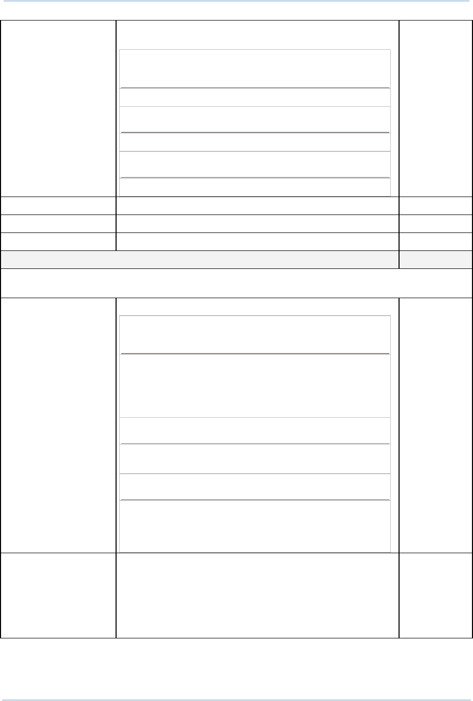
SYMBOLOGY SETTINGS TABLE
2D Description Default
Codabar Enable
CLSI Editing When applied, the CLSI editing strips the start/stop
characters and inserts a space after the first, fifth, and
tenth characters of a 14-character Codabar barcode.
The 14-character barcode length does not include
start/stop characters.
No
NOTIS Editing Decide whether to include the start/stop characters in the
data being transmitted.
NOTIS Editing is to strip the start/stop characters, i.e.
to disable "Transmit Start/Stop Characters".
No
Select Length One or two fixed lengths
Range (1~55) 4~55
Code 128 ---
Code 128 Read standard Code 128 barcodes (=without leading FNC1
character). Enable
UCC/EAN-128 Read UCC/EAN-128 barcodes with leading FNC1 character. Enable
ISBT 128 Read ISBT 128 barcodes. Enable

37
Appendix III 2D Scan Engine
Industrial 25 (= Discrete 25) Enable
Select Length One or two fixed lengths
Range (1~55) 4~55
Interleaved 25 Enable
Convert to EAN-13 Convert a 14-character barcode into EAN-13 if the
following requirements are met:
The barcode must have a leading 0 and a valid EAN-13
check digit.
“Verify Checksum” must be disabled.
No
Verify Checksum Decide whether to verify the checksum. If desired, select
one of the algorithms below. If the checksum is incorrect,
the barcode will not be accepted.
No
USS algorithm
OPCC algorithm
No
Transmit Checksum Decide whether to include the checksum in the data being
transmitted.
"Verify Checksum" must be enabled so that the
checksum can be left out (= "Transmit Checksum"
disabled).
No
Select Length One or two fixed lengths
Range (1~55) 4~55
Code 39 Enable
Convert to Code 32 Convert to Italian Pharmacode. No
Code 32 Prefix Prefix character "A" to Code 32 barcodes. No
Verify Checksum Decide whether to verify the checksum. If the checksum is
incorrect, the barcode will not be accepted. No
Transmit Checksum Decide whether to include the checksum in the data being
transmitted.
"Verify Checksum" must be enabled so that the
checksum can be left out (= "Transmit Checksum"
disabled).
No
Code 39 Full ASCII Code 39 Full ASCII includes all the alphanumeric and
special characters. Disable
Select Length One or two fixed lengths
Range (1~55) 4~55
Trioptic Code 39 Disable
Code 93 Enable
Select Length One or two fixed lengths
Range (1~55) 4~55

38
9300 Mobile Compute
r
Reference Manual
MSI Enable
Verify Checksum If Two Check Digits option is selected, an additional
verification is required to ensure integrity. Select one of
the algorithms below. If the checksum is incorrect, the
barcode will not be accepted.
Check Digit Algorithm
One Check Digit Single Modulo 10
Two Check Digits Mod 10/Mod 11
Mod 10/Mod 10
Single Modulo
10
Transmit Checksum Decide whether to include the checksum in the data being
transmitted. No
Select Length One or two fixed lengths
Range (1~55) 4~55
RSS ---
RSS-14 Enable
RSS Limited Enable
RSS Expanded Enable
Convert RSS to
UPC/EAN
"Convert to UPC/EAN" only applies to RSS-14 and RSS
Limited barcodes not decoded as part of a Composite
barcode.
Convert to EAN-13
Strip the leading "010" from barcodes.
"01" is the Application ID and must be followed by a
single zero (the first digit encoded)
Convert to UPC-A
Strip the leading "0100" from barcodes.
"01" is the Application ID and must
be followed by
two or more zeros (but not six zeros)
No
EAN-8 Enable
Convert to EAN-13 The EAN-8 barcode will be expanded into EAN-13, and the
next processing will follow the settings configured for
EAN-13.
No
Addon 2 / Addon 5 Refer to UPC/EAN Addon setting.
EAN-13 Enable
Bookland EAN (=
ISBN) The EAN-13 barcode starting with 978 will be converted to
ISBN. Yes
Addon 2 / Addon 5 Refer to UPC/EAN Addon setting.
UPC-A Enable
Transmit Checksum Decide whether to include the UPC-A checksum in the data
being transmitted. Yes
Transmit Preamble Decide whether to include the UPC-A preamble System
Number (and Country Code) in the data being transmitted. System
Number
Addon 2 / Addon 5 Refer to UPC/EAN Addon setting.
UPC-E0 Enable

39
Appendix III 2D Scan Engine
Transmit Checksum Decide whether to include the UPC-E0 checksum in the
data being transmitted. Yes
Transmit Preamble Decide whether to include the UPC-E0 preamble System
Number (and Country Code) in the data being transmitted. System
Number
Addon 2 / Addon 5 Refer to UPC/EAN Addon setting.
Convert to UPC-A The UPC-E0 barcode will be expanded into UPC-A, and the
next processing will follow the settings configured for
UPC-A.
No
UPC-E1 Disable
Transmit Checksum Decide whether to include the UPC-E1 checksum in the
data being transmitted. Yes
Transmit Preamble Decide whether to include the UPC-E1 preamble System
Number (and Country Code) in the data being transmitted. System
Number
Addon 2 / Addon 5 Refer to UPC/EAN Addon setting.
Convert to UPC-A The UPC-E1 barcode will be expanded into UPC-A, and the
next processing will follow the settings configured for
UPC-A.
No
UCC Coupon Extended Code Disable
Read UPC-A barcodes starting with digit "5", EAN-13 barcodes starting with digits "99", and
UPC-A/EAN-128 Coupon Codes.
UPC-A, EAN-13, and EAN-128 must be enabled first!
Use “Addon Redundancy” to control auto-discrimination of the EAN-128 (right half) of a coupon
code.
UPC/EAN Addon ---
Addon 2 / Addon 5 Decide whether to decode EAN-8, EAN-13, UPC-E0,
UPC-E1, UPC-A with supplementals.
Ignore Supplementals
Decode Only With Supplementals
Decode With Supplementals (= Auto-discriminate)
Ignore...
Addon Redundancy When "Decode with Supplementals" is applied, decide the
number of times of supplementary decoding the same
barcode that makes a valid reading.
10 times
Code 11 Enable
Verify Checksum Decide whether to verify the checksum. If the checksum is
incorrect, the barcode will not be accepted.
No verification
One Check Digit
Two Check Digits
No
Transmit Checksum Decide whether to include the checksum in the data being
transmitted.
"Verify Checksum" must be enabled so that the
checksum can be left out (= "Transmit Checksum"
disabled).
No

40
9300 Mobile Compute
r
Reference Manual
Select Length One or two fixed lengths
Range (1~55) 4~55
Postal Codes ---
US Postnet Enable
US Planet Enable
Transmit US Postal
Checksum US Postnet or US Planet must be enabled first! Enable
UK Postal Enable
Transmit UK Postal
Checksum UK Postal must be enabled first! Enable
Japan Postal Enable
Australian Postal Enable
Dutch Postal Enable
Composite Codes ---
Composite CC-C Enable
Composite CC-A/B Disable
Composite TLC-39 Disable
UCC/EAN Code 128
Emulation Mode Transmit data as if it was encoded in Code 128 barcodes.
Transmit AIM Code Identifier must be enabled first!
Disable
UPC barcodes can be "linked" with a 2D barcode during
transmission as if they were one barcode. UPC Always
Linked
UPC Composite Mode
UPC Never Linked
Transmit UPC barcodes regardless of whether a 2D
barcode is detected.
UPC Always Linked
Transmit UPC barcodes and the 2D portion. If the 2D
portion is not detected, the UPC barcode will not be
transmitted.
CC-A/B or CC-C must be enabled!
Auto-discriminate UPC Composites
Transmit UPC barcodes as well as the 2D portion if
present.
2D Symbologies ---
PDF417 Enable
MicroPDF417 Disable
MicroPDF417 Code 128
Emulation
T
ransmit data from certain MicroPDF417 barcodes as if it
was encoded in Code 128 barcodes.
Transmit AIM Code Identifier must be enabled first!
Disable
41
Appendix III 2D Scan Engine
When applied, the MicroPDF417 barcodes are transmitted
with one of these prefixes:
The first codeword of MicroPDF417 is 903-907, 912,
914, 915:
The original Code ID "]L3" will be changed to "]C1".
The first codeword of MicroPDF417 is 908 or 909:
The original Code ID "]L4" will be changed to "]C2".
The first codeword of MicroPDF417 is 910 or 911:
The original Code ID "]L5" will be changed to "]C0".
Data Matrix Enable
Maxicode Enable
QR Code Enable
2D Symbologies - Macro PDF ---
Macro PDF is a special feature for concatenating multiple PDF barcodes into one file, known as
Macro PDF417 or Macro MicroPDF417.
Transmit/Decode Mode
Decide how to handle Macro PDF decoding.
Buffer All Symbols / Transmit Macro PDF When
Complete
Transmit all decoded data from an entire Macro PDF
sequence only when the entire sequence is scanned and
decoded. If the decoded data exceeds the limit of 50
symbols, no transmission because the entire sequence
was not scanned!
Transmit Any Symbol in Set / No Particular Order
Transmit data from each Macro PDF symbol as decoded,
regardless of the sequence.
Passthrough All Symbols
Transmit and decode all Macro PDF symbols and
perform no processing. In this mode, the host is
responsible for detecting and parsing the Macro PDF
sequences.
Passthrough
All Symbols
ESC Characters When enabled, it uses the backslash "\" as an Escape
character for systems that can process transmissions
containing special data sequences. It will format special
data according to the Global Label Identifier (GLI)
protocol, which only affects the data portion of a Macro
PDF symbol transmission. The Control Header, if enabled,
is always sent with GLI formatting.
None

42
9300 Mobile Compute
r
Reference Manual
Note: When printing barcodes, keep each Macro PDF sequence separate, as each has a
unique identifier. Do not mix barcodes from several Macro PDF sequences, even if
they encode the same data. When you scan Macro PDF sequences, scan the entire
Macro PDF sequence without interruption!
Image Capture Disable
Image Capture
Illumination Decide whether to flash illumination on every image
capture to aid decoding.
Turn On (Internal LED )
Turn Off
On
Image Capture
Autoexposure Decide whether to manually specify the gain and exposure
time (only recommended for advanced users with difficult
image capture situations).
On
Gain Time Only applies when Image Capture Autoexposure is
disabled.
Gain is a means of amplifying the raw image data
before it is converted into 256 grayscale values.
Increasing the gain increases brightness and contrast,
but also increases noise (undesired electrical
fluctuations in the image) which makes the image less
attractive and/or harder to decode.
Set the manual gain time in the range of 79~127.
100
Exposure Time Only applies when Image Capture Autoexposure is
disabled.
Exposure Time controls the amount of time the CCD is
allowed to collect light, much like the shutter speed for
a camera.
Generally, the brighter the environment, the
lower the exposure time. Increasing the exposure time
past 20 ms in a handheld application increases the risk
of blurring the image due to hand jitter.
Set the manual exposure time to one of the following
values — 5 ms, 10 ms, 15 ms, 20 ms, 25 ms, or 30
ms.
10 ms
Snapshot Aiming
Pattern Decide whether to project the aim pattern while capturing
an image. On
Image Resolution Decide how to alter image resolution before compression.
Multiple pixels are combined to one pixel, resulting in a
smaller image containing the original content with reduced
resolution.
640×480 (Full resolution)
320×240 (Half resolution)
212×160 (1/3 resolution)
160×1420 (1/4 resolution)
640×480
Image Format Decide in which file format the image is saved.
JPEG file format
BMP file format
JPEG

43
Appendix III 2D Scan Engine
Optimized for JPEG
Quality Decide whether JPEG images are optimized for quality.
Cancel the check box so that JPEG images are
optimized for size.
Enable
Select JPEG Quality Set a value from 5 to 100, where “100” represents the
highest quality image. 65
Select JPEG Size Set a value from 5 to 150, which represents the file size in
multiples of 1024 bytes (1K). For example, setting this
value to 8 permits the file size to be as large as 8192
bytes.
40
Bits per Pixel Select the number of significant bits per pixel (BPP) to use
when capturing an image.
1 bit per pixel (for black and white images)
4 BPP (to assign 1 of 16 levels of grey to each pixel)
8 BPP (to assign 1 of 256 levels of grey to each pixel)
8
Note: (1) For JPEG files, these BPP settings are ignored for it always uses 8 bits per pixel!
(2) When the image capture feature is enabled, press the [SCAN] button and it will
capture an image instead of reading a barcode.
Miscellaneous Options ---
Transmit Code ID Decide whether to include AIM Code ID in the beginning of
data. Each AIM Code ID contains the three-character string
“]cm” –
] = Flag Character (ASCII 93)
c = Code Character (see below)
m = Modifier Character (see below)
Disable

44
9300 Mobile Compute
r
Reference Manual
AIM CODE ID – CODE CHARACTERS
Code Character Code Type
A Code 39, Code 39 Full ASCII, Code 32
C Code 128, Coupon (Code 128 portion)
d Data Matrix
E UPC/EAN, Coupon (UPC portion)
e RSS Family
F Codabar
G Code 93
H Code 11
I Interleaved 25
L PDF417, Macro PDF417, Micro PDF417
M MSI
Q QR Code
S Discrete 25, IATA 2 of 5
U Maxicode
X Code 39 Trioptic, Bookland EAN, US Postnet, US Planet, UK Postal, Japan
Postal, Australian Postal, Dutch Postal
AIM CODE ID – MODIFIER CHARACTERS
Code Type Option Value Option
0 No check character or Full ASCII processing.
1 Checksum has been verified.
3 Checksum has been verified and stripped.
4 Full ASCII conversion has been performed.
5 Result of option values 1 and 4.
Code 39
7 Result of option values 3 and 4.
0 Standard data packet. No Function Code 1“FNC1” in the first
character position.
1 Function Code 1“FNC1” in the first character position.
Code 128
2 Function Code 1“FNC1” in the second character position.
0 No check digit processing.
1 Checksum has been verified.
Interleaved 25
3 Checksum has been verified and stripped.
Codabar 0 No check digit processing.
Code 93 0 Always transmit 0.

45
Appendix III 2D Scan Engine
0 Modulo 10 check digit verified and transmitted. MSI
1 Modulo 10 check digit verified but not transmitted.
Discrete 25 0 Always transmit 0.
0 Standard data packet in full EAN country code format, which
is 13 digits for UPC-A and UPC-E (not including
supplemental data).
3 Standard data packet with two-digit or five-digit
supplemental data.
4 EAN-8 data packet.
UPC/EAN
A UPC-A with Addon 2 barcode, 012345678905-10, is transmitted to the host
as a 18-character string, ]E3001234567890510.
Bookland EAN 0 Always transmit 0.
Trioptic Code 39 0 Always transmit 0.
0 Single check digit (has been verified.)
1 Two check digits (has been verified.)
Code 11
3 Checksum has been verified but not transmitted.
0 Always transmit 0. RSS Family
RSS-14 and RSS Limited will be transmitted with an Application Identifier
“01”. For example, an RSS-14 barcode, 100123456788902, is transmitted
as ]e001100123456788902.
Note: In UCC/EAN-128 emulation mode, RSS is transmitted using Code 128 rules (i.e.
“]C1”).
Native mode transmission
0 Standard data packet
1 Data packet containing the data following an encoded
symbol separator character.
2 Data packet containing the data following an escape
mechanism character. The data packet does not support the
ECI protocol.
3 Data packet containing the data following an escape
mechanism character. The data packet supports the ECI
protocol.
UCC/EAN-128 emulation
EAN.UCC
Composites (RSS,
UCC/EAN-128, 2D
portion of UPC
composite)
1 Data packet is a UCC/EAN-128 barcode (i.e. data is
preceded with “]JC1”).
Note: UPC portion of composite is transmitted using UPC rules.
PDF417,
Micro PDF417
0 Scan engine is set to conform to protocol defined in 1994
PDF417 symbology specifications.
When this option is transmitted, the receiver cannot
reliably determine whether ECIs have been invoked or
whether data byte 92DEC has been doubled in

46
9300 Mobile Compute
r
Reference Manual
transmission.
1 Scan engine is set to follow the ECI protocol (Extended
Channel Interpretation). All data characters 92DEC are
doubled.
2 Scan engine is set for Basic Channel operation (no escape
character transmission protocol). Data characters 92DEC
are not doubled.
When decoders are set to this mode, unbuffered Macro
symbols and symbols requiring the decoder to convey
ECI escape sequences cannot be transmitted.
3 The barcode contains a UCC/EAN-128 symbol, and the first
codeword is 903-907, 912, 914, 915.
4 The barcode contains a UCC/EAN-128 symbol, and the first
codeword is in the range 908-909.
5 The barcode contains a UCC/EAN-128 symbol, and the first
codeword is in the range 910-911.
A PDF417 barcode, ABCD, with no transmission protocol enabled, is
transmitted as ]L2ABCD.
0 ECC 000-140, not supported.
1 ECC 200.
2 ECC 200, FNC1 in first or fifth position.
3 ECC 200, FNC1 in second or sixth position.
4 ECC 200, ECI protocol implemented.
5 ECC 200, FNC1 in first or fifth position, ECI protocol
implemented.
Data Matrix
6 ECC 200, FNC1 in second or sixth position, ECI protocol
implemented.
0 Mode 4 or 5
1 Mode 2 or 3
2 Mode 4 or 5, ECI protocol implemented.
Maxicode
3 Mode 2 or 3, ECI protocol implemented in secondary
message.
0 Model 1
1 Model 2, ECI protocol not implemented.
2 Model 2, ECI protocol implemented.
3 Model 2, ECI protocol not implemented, FNC1 implied in
first position.
4 Model 2, ECI protocol implemented, FNC1 implied in first
position.
5 Model 2, ECI protocol not implemented, FNC1 implied in
second position.
QR Code
6 Model 2, ECI protocol implemented, FNC1 implied in second
position

47
Appendix III 2D Scan Engine
User Manual

Windows CE Mobile Compute
r
9300
Version 0.09

Copyright © 2009 CIPHERLAB CO., LTD.
All rights reserved
The software contains proprietary information of CIPHERLAB CO., LTD.; it is provided
under a license agreement containing restrictions on use and disclosure and is also
protected by copyright law. Reverse engineering of the software is prohibited.
Due to continued product development this information may change without notice. The
information and intellectual property contained herein is confidential between CIPHERLAB
and the client and remains the exclusive property of CIPHERLAB CO., LTD. If you find
any problems in the documentation, please report them to us in writing. CIPHERLAB
does not warrant that this document is error-free.
No part of this publication may be reproduced, stored in a retrieval system, or
transmitted in any form or by any means, electronic, mechanical, photocopying,
recording or otherwise without the prior written permission of CIPHERLAB CO., LTD.
For product consultancy and technical support, please contact your local sales
representative. Also, you may visit our web site for more information.
The CipherLab logo is a registered trademark of CIPHERLAB CO., LTD.
Microsoft, Windows, and the Windows logo are registered trademarks of Microsoft
Corporation in the United States and/or other countries.
Bluetooth is a trademark of Bluetooth SIG, Inc., U.S.A.
Other product names mentioned in this manual may be trademarks or registered
trademarks of their respective companies and are hereby acknowledged.
The editorial use of these names is for identification as well as to the benefit of the
owners, with no intention of infringement.
CIPHERLAB CO., LTD.
Website: http://www.cipherlab.com

IMPORTANT NOTICES
FOR USA
This equipment has been tested and found to comply with the limits for a Class B digital
device, pursuant to Part 15 of the FCC Rules. These limits are designed to provide
reasonable protection against harmful interference in a residential installation. This
equipment generates, uses and can radiate radio frequency energy and, if not installed
and used in accordance with the instructions, may cause harmful interference to radio
communications. However, there is no guarantee that interference will not occur in a
particular installation. If this equipment does cause harmful interference to radio or
television reception, which can be determined by turning the equipment off and on, the
user is encouraged to try to correct the interference by one or more of the following
measures:
Reorient or relocate the receiving antenna.
Increase the separation between the equipment and receiver.
Connect the equipment into an outlet on a circuit different from that to which the
receiver is connected.
Consult the dealer or an experienced radio/TV technician for help.
This device complies with Part 15 of the FCC Rules. Operation is subject to the following
two conditions: (1) This device may not cause harmful interference, and (2) this device
must accept any interference received, including interference that may cause undesired
operation.
FOR CANADA
This digital apparatus does not exceed the Class B limits for radio noise emissions from
digital apparatus as set out in the interference-causing equipment standard entitled
"Digital Apparatus," ICES-003 of Industry Canada.
This device complies with Part 15 of the FCC Rules. Operation is subject to the following
two conditions: (1) This device may not cause harmful interference, and (2) this device
must accept any interference received, including interference that may cause undesired
operation.
Cet appareil numerique respecte les limites de bruits radioelectriques applicables aux
appareils numeriques de Classe B prescrites dans la norme sur le material brouilleur:
"Appareils Numeriques," NMB-003 edictee par l'Industrie.
FOR HAND-HELD PRODUCT WITH RF FUNCTIONS
This equipment complies with FCC radiation exposure limits set forth for an uncontrolled
environment. This equipment should be installed and operated with minimum distance 20
cm between the radiator & your body. It only operated in hand-held used.

If you only transfer data to Host by WLAN/Bluetooth, please keep the minimum distance
20 cm between machine & your body.
FOR PRODUCT WITH LASER
Per FDA and IEC standards, the scan engines described in this manual are not given a
laser classification. However, the following precautions should be observed:
CAUTION
This laser component emits FDA / IEC Class 2 laser light at the exit port. Do not
stare into beam.
SAFETY PRECAUTIONS
RISK OF EXPLOSION IF BATTERY IS REPLACED BY AN INCORRECT TYPE.
DISPOSE OF USED BATTERIES ACCORDING TO THE INSTRUCTIONS.
The maximum level of Specific Absorption Rate (SAR) measured is 0.211 W/kg.
The use of any batteries or charging devices, which are not originally sold or
manufactured by CipherLab, will void your warranty and may cause damage to
human body or the product itself.
DO NOT disassemble, incinerate or short circuit the battery.
DO NOT expose the scanner or the battery to any flammable sources.
For green-environment issue, it's important that batteries should be recycled in a
proper way.
Under no circumstances, internal components are self-serviceable.
The charging and communication cradle uses an AC power adaptor. A socket outlet
shall be installed near the equipment and shall be easily accessible. Make sure there
is stable power supply for the mobile computer or its peripherals to operate properly.
CARE & MAINTENANCE
This mobile computer is intended for industrial use. The mobile computer is rated IP
54, however, it may do damage to the mobile computer when being exposed to
extreme temperatures or soaked wet.
When the body of the mobile computer gets dirty, use a clean and wet cloth to wipe
off the dust. DO NOT use/mix any bleach or cleaner. Always keep the LCD dry.
For a liquid crystal display (LCD) or touch screen, use a clean, non-abrasive, lint-free
cloth to wipe dust off the screen. DO NOT use any pointed or sharp object to move
against the surface.
If you want to put away the mobile computer for a period of time, download the
collected data to a host computer, and then take out the battery pack. Store the
mobile computer and battery pack separately.
When the mobile computer resumes its work, the main and backup batteries will take
a certain time to become fully charged.
If you shall find the mobile computer malfunctioning, write down the specific scenario
and consult your local sales representative.

RELEASE NOTES
Version Date Notes
1.00 Initial release
0.09 Jun. 16, 2009 First draft
FCC Caution: Any changes or modifications not expressly approved by the party
responsible for compliance could void the user's authority to operate this equipment.
This device and its antenna(s) must not be co-located or operating in conjunction with any
other antenna or transmitter.

CONTENTS
IMPORTANT NOTICES ................................................................................- 3 -
For USA..............................................................................................- 3 -
For Canada..........................................................................................- 3 -
For Hand-held Product with RF Functions.....................................................- 3 -
For Product with Laser ...........................................................................- 4 -
Safety Precautions.................................................................................- 4 -
Care & Maintenance...............................................................................- 4 -
RELEASE NOTES.......................................................................................- 5 -
INTRODUCTION........................................................................................... 1
Getting Familiarized with 9300 .....................................................................2
Installing the Hand Strap .........................................................................3
Charging the Battery ..............................................................................4
Features.................................................................................................5
Inside the Package ....................................................................................5
Accessories .............................................................................................6
USING 9300 MOBILE COMPUTER...................................................................... 7
1.1 Battery..............................................................................................7
1.1.1 Inserting the Battery .......................................................................7
1.1.2 Charging the Battery .......................................................................9
1.1.3 Understanding the Battery Icons .........................................................9
1.1.4 Power Management....................................................................... 10
1.2 Memory........................................................................................... 11
1.2.1 Caution of Data Loss...................................................................... 11
1.2.2 Inserting the SD Card..................................................................... 11
1.3 Keypad............................................................................................ 12
1.3.1 Keypad Settings ........................................................................... 12
1.3.2 29-key Keypad............................................................................. 13
1.3.3 43-key Keypad............................................................................. 15
1.3.4 Function Key............................................................................... 16
1.3.5 Programmable Keys....................................................................... 16
1.4 Touch Screen .................................................................................... 17
1.4.1 Adjusting the Backlight .................................................................. 17
1.4.2 Re-calibrating the Screen................................................................ 18
1.5 Notifications ..................................................................................... 19
1.5.1 Status LED.................................................................................. 19
1.5.2 Audio........................................................................................ 19
1.5.3 Vibrator..................................................................................... 20
1.6 Data Capture .................................................................................... 20
1.6.1 Barcode & RFID Reader .................................................................. 20

9300 Mobile Compute
r
Reference Manual
SPECIFICATIONS.........................................................................................21
Platform, Processor & Memory.................................................................... 21
Communications & Data Capture ................................................................. 21
Electrical Characteristics........................................................................... 22
Physical Characteristics ............................................................................ 22
Environmental Characteristics..................................................................... 23
Programming Support............................................................................... 23
Accessories ........................................................................................... 24
SCAN ENGINE SETTINGS ...............................................................................25
Symbologies Supported ............................................................................. 25
RFID Tags Supported ................................................................................ 27
CCD/LASER SCAN ENGINE .............................................................................29
Reader Settings Table .............................................................................. 29
Symbology Settings Table .......................................................................... 30
2D SCAN ENGINE........................................................................................35
Reader Settings Table .............................................................................. 35
Symbology Settings Table .......................................................................... 36
AIM Code ID – Code Characters................................................................. 44
AIM Code ID – Modifier Characters............................................................. 44

1
INTRODUCTION
9300 Mobile Computer, running Windows CE 6.0 in palm size, is our first product line of
rugged PDA-style Mobile Computer. Light-weight, streamlined and ergonomic, it adds
even more powerful and handy tools to delivering the flexibility in customization.
Specifically designed to work as an industrial PDA, 9300 Mobile Computer provides rich
options of data collection, voice and data communications, long-lasting working hours,
and so on. Its large color transflective TFT display guarantees ease in reading in all
lighting conditions. Integrated with Bluetooth and 802.11b/g technologies, you may
choose to add the GSM/GPRS module to gain greater speeds and optimal mobility.
This manual serves to guide you through how to install, configure, and operate the
mobile computer. The Care & Maintenance section is specifically prepared for those who
are in charge of taking care of the mobile computer.
We recommend you to keep one copy of the manual at hand for quick reference or
maintenance purposes. To avoid any improper disposal or operation, please read the
manual thoroughly before use.
Thank you for choosing CipherLab products!
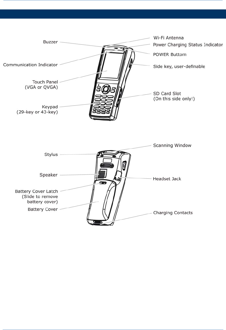
2
9300 Mobile Compute
r
Reference Manual
GETTING FAMILIARIZED WITH 9300
Figure 1: Overview
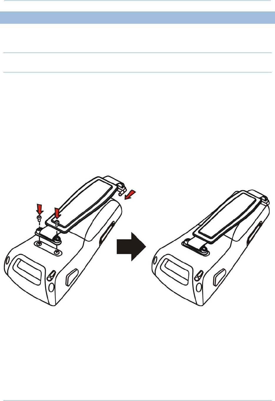
3
Introduction
INSTALLING THE HAND STRAP
The hand strap is ideal for one-handed operation, which requires safe and convenient
hold of the mobile computer.
Warning: Always make sure the hand strap is well hooked and screwed to the back
of the mobile computer before use.
When the hand strap is desired, install it to the mobile computer by following these
steps:
1) Place the mobile computer face down on a flat and clean surface.
2) Screw one end of the hand strap to the back of the mobile computer.
3) Insert and hook the other end of the hand strap to the bottom of the mobile
computer.
4) Make sure the hand strap is securely attached to the mobile computer.
5) Adjust the length of the hand strap to suit your handbreadth.
Figure 2: Installing the Hand Strap
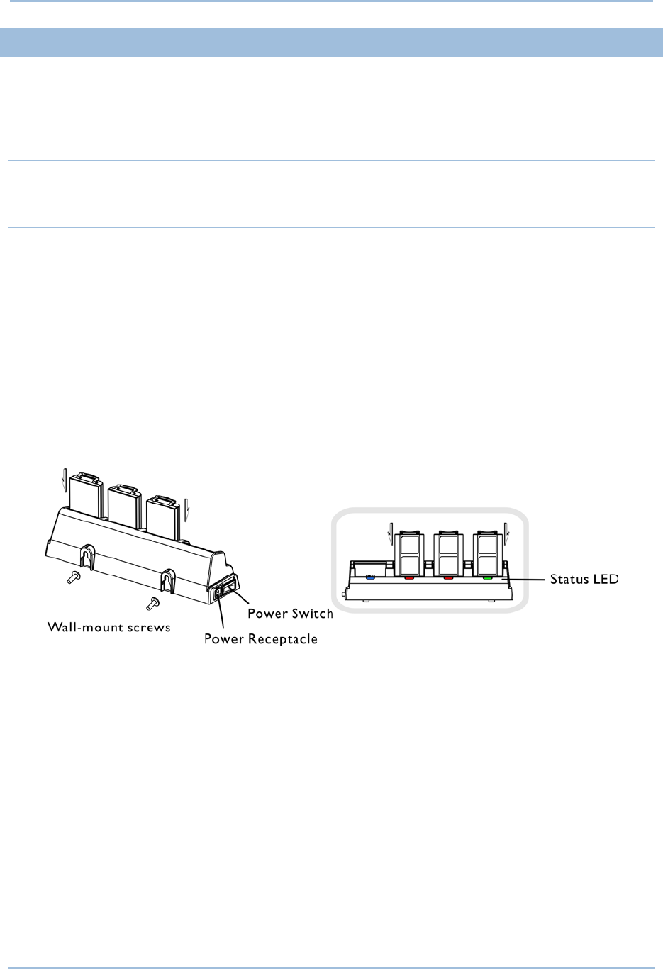
4
9300 Mobile Compute
r
Reference Manual
CHARGING THE BATTERY
You can use a cradle or charger to charge the Mobile Computer and/or its battery. Below
are the 4-Slot Battery Charger and 4-Slot Charging Cradle for 9300. The 4-Slot Battery
Charger can be mounted on table or wall. Drill two holes (centers spaced 105 millimeters
apart), secure the two supplied screws, and mount the charger by sliding over screws.
Warning: It is recommended that the charging devices be operated at room
temperature (18°C to 25°C) for optimal performance. The charging devices
will not charge the battery when the temperature exceeds 40°C.
1) Seat batteries with contacts facing to back in the 4-Slo Battery Charger (top), or seat
the mobile computers in the 4-Slot Charging Cradle (bottom).
2) Connect the power supply cord to the power receptacle on the charger or cradle.
3) Connect the other end of the power cord to a suitable power outlet.
4) Press the power switch on, and the charger’s LED or the Power LED on the cradle will
be blue.
5) For the 4-Slot Battery Charger, the LED will be red while charging, and will be green
when fully charged.
For the 4-Slot Charging Cradle, the LED on each of the mobile computers will be red
while charging, and will be green when fully charged.
Figure 3: 4-Slot Battery Charger

5
Introduction
FEATURES
Ergonomic design - ruggedized yet streamlined, with hand strap for secure hold.
Built tough to survive drop test and sealed against moisture/dust to industrial
standard IP 64.
Microsoft Windows CE 6.0 operating system, 624 MHz Marvell PXA310 processor
512 MB non-volatile NAND flash memory to store OS and software programs
(part of the free space is used as a storage card called DiskOnChip)
256 MB on-board DDR SDRAM to store and run programs, as well as store program
data
One SD expansion slot for memory card
Dual mode support - One scan engine (integrated barcode scanner/imager) plus one
RFID reader
Ambidextrous side triggers
Total wireless solution - connectivity includes Bluetooth, 802.11b/g and
GSM/EDGE/GPRS.
A 2.8" color transflective TFT display delivers excellent visibility in all lighting
conditions.
Programmable feedback includes buzzer, speaker and vibrator.
Built-in power tools include Reader Configuration Utility, Backup Utility, etc.
Terminal Emulation client for VT100/220 and IBM 5250 enables a quick link to any
backend database.
Application Generator (AG*.exe for desktop PC) enables easy customization of data
collection applications.
Programming support includes Reader DLL and System APIs.
Accessories and peripherals include pistol grip, international AC charging cradle, etc.
INSIDE THE PACKAGE
The following items are included in the package. Save the box and packaging material for
future use in case you need to store or ship the mobile computer.
9300 Mobile Computer
Rechargeable Li-ion battery pack
Stylus
Hand Strap
Software & Manual CD
Note: For battery charging, you will need to purchase a charging cradle separately.

6
9300 Mobile Compute
r
Reference Manual
ACCESSORIES
Rich choices of optional accessories are available for you to enhance the total
performance of the mobile computer.
Protective Cover
SD Memory Card
Spare rechargeable Li-ion battery, standard or high capacity pack
4-slot Battery Charger
Charging & Communication Cradle

Chapter 1
USING 9300 MOBILE COMPUTER
This chapter explains the features and usage of 9300 Mobile Computer.
IN THIS CHAPTER
1.1 Battery....................................................................... 7
1.2 Memory.................................................................... 11
1.4 Touch Screen............................................................ 17
1.5 Notifications.............................................................. 19
1.6 Data Capture ............................................................ 20
1.1 BATTERY
Main Battery
9300 Mobile Computer is powered by a rechargeable 3.7 V/2700 mAh Li-ion battery
pack, and it takes approximately 4 hours to fully charge it. However, the charging
time may vary by working condition. During normal operation, the mobile computer
can work for up to 10 hours.
Backup Battery
The backup battery on the main board takes charge when the main battery is
removed or drained out. When fully charged, the 3.6 V/15 mAh rechargeable Lithium
button cell helps retain data in SRAM and maintain the system running in suspend
mode for at least 20 hours without the main battery. In the meantime, you have to
replace the main battery as soon as possible.
1.1.1 INSERTING THE BATTERY
When you first receive the package, the rechargeable functionality of the backup battery
is turned off. It is controlled by a DIP switch inside the battery compartment as shown
below.
For shipping and storage purposes, save the mobile computer and the main battery in
separate packages, and adjust the DIP switch to the OFF position (bottom). This will keep
both batteries in good condition for future use.
Note: Any improper handling may reduce the battery life.
1) Remove the hand strap.
2) Hold the mobile computer still. Press the battery cover latch and slide it to unlock the
battery cover.
3) Remove the battery cover.
7
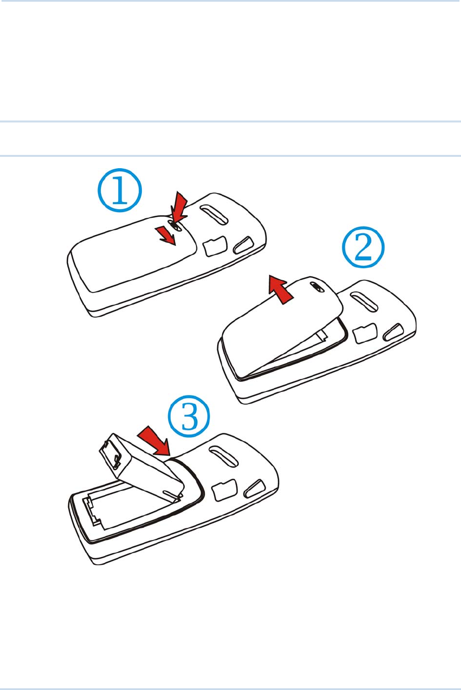
8
9300 Mobile Compute
r
Reference Manual
4) Insert the battery pack into the battery compartment at a proper angle (30°~45°) so
that the metal contacts on the battery are met with the charging contacts inside the
compartment. Make sure that the battery is snugly fit into the compartment.
5) Put the battery cover back onto the mobile computer until it clicks into place.
6) If the battery is charged, the mobile computer turns on.
If the mobile computer does not turn on, charge the battery.
Note: For a new battery, make sure it is fully charged before use. Always prepare a
spare battery pack, especially when you are on the road.
Figure 4: Installing the Main Battery

9
Specifications
1.1.2 CHARGING THE BATTERY
The main and backup batteries may not be charged to full for shipment. When you first
receive the package, you will need to charge batteries to full before using the mobile
computer.
Note: To charge the batteries to full, it requires approximately 8 hours for the first time.
After the initial charging, it takes only 4 hours to charge the batteries to full.
Because the internal backup battery is constantly charged from the main battery, the
initial charging requires inserting the battery pack to the mobile computer and then
seating the mobile computer in the cradle for charging. This will have both the main and
backup batteries charged at the same time. To charge the backup battery, make sure
that you slide the DIP switch inside the battery compartment to the ON position.
Note: For a new battery, make sure it is fully charged before use. Always prepare a
spare battery pack, especially when you are on the road.
1.1.3 UNDERSTANDING THE BATTERY ICONS
The battery pack is the only power source for the mobile computer to work. It also
charges the backup battery on the main board so that the data stored in SRAM can be
retained properly. Therefore, when the main battery charge goes low, you need to
replace the battery pack with a charged one or charge it as soon as possible. Most of all,
always save data before it is too late; you should backup important data on a regular
basis.
Double-tap a battery icon so that you can quickly access the [Power Properties] dialog
box.
Battery Status Icons Description
Battery charge remaining in the main battery –
The more bars, the more
power in the main battery.
Main battery is ready for charging.
Main battery charge becomes low and needs charging.
Main battery charge becomes very low and needs charging immediately.
Warning: Data loss may occur with SRAM during low battery condition. Always save
data before running out of power or keep a fresh battery for replacement.
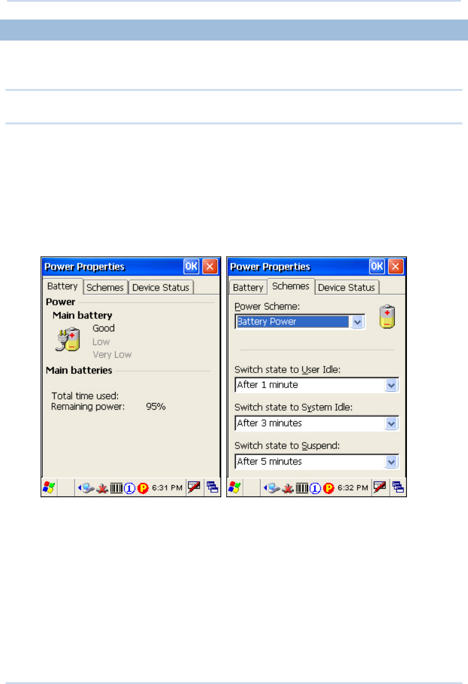
10
9300 Mobile Compute
r
Reference Manual
1.1.4 POWER MANAGEMENT
For any portable device, power management is a critical issue especially when you are on
the road. Below are some tips to help you save battery power.
Warning: Using backlight, wireless connectivity, and peripherals while on battery
power will substantially reduce battery power.
To speed up charging the mobile computer, turn off the mobile computer and seat it
in the cradle.
Bring a second battery pack on the road.
Stop wireless connectivity, Bluetooth, 802.11b/g or GSM/GPRS that is not in use.
Go to Start > Settings > Control Panel and double-tap the Display icon. Refer to
1.4.1 Adjusting the Backlight.
Go to Start > Settings > Control Panel and double-tap the Power icon. (below)
1. In the Battery tab (left below), you can always monitor the charging status.
2. Tap the Schemes tab. (right above)
3. Select the desired power scheme and options for suspending operation when not
in use. The system can be set to three different states to conserve power:
User Idle state
System Idle state
Suspend state
The time choices represent the amount of time that must pass before the system
will switch to the next power conservation state.

11
Specifications
1.2 MEMORY
Read-only Memory (ROM)
512 megabytes flash memory for storing OS (Windows CE 6.0) and custom
application programs. Yet a portion of the memory is referred to as DiskOnChip,
which can store data and programs that you wish to retain even after hardware reset.
Random-access Memory (RAM)
256 megabytes SDRAM for storing and running programs, as well as storing program
data. Its contents will be retained by the backup battery.
Expansion Slot
The mobile computer is equipped with one SD card slot, which is user accessible. You
may upgrade memory by inserting an optional SD memory card.
1.2.1 CAUTION OF DATA LOSS
When the main battery is removed or drained, the backup battery on the main board is
to retain the contents of SRAM and maintain the OS in suspend mode for at least 20
hours, on condition that the backup battery has already been fully charged.
If you want to put away the mobile computer for a couple of days, you should be aware
that data loss occurs when both the main and backup batteries discharge completely.
Therefore, it is necessary to backup data and files before putting away the mobile
computer!
1.2.2 INSERTING THE SD CARD
If you wish to expand memory, follow these steps to insert a memory card into the SD
card slot:
1) Press for the mobile computer to enter suspend mode.
2) Place the mobile computer face down on a flat and clean surface.
3) Remove the side plate by unscrewing the two screws (on the right side when you
place the mobile computer face down) as shown below.
4) Insert the SD card properly.

12
9300 Mobile Compute
r
Reference Manual
5) Replace the side plate and tighten the screws.
Warning: Make sure the mobile computer is set to Suspend mode; otherwise, it may
cause damage to the mobile computer.
Figure 5: Inserting the SD Card
REMOVING THE SD CARD
If you wish to remove the SD card, simply push the card after removing the side plate.
The SD card will be rejected automatically.
1.3 KEYPAD
Silicon rubber has been chosen for their durability and prompt feedback.
Note: Functionality of keys is application-dependent.
1.3.1 KEYPAD SETTINGS
Press [FN] first, and then [0].
The LED backlight of keypad is turned off by default. It can be toggled ON/OFF by the
key combination: [FN] + [0]. It is suggested to turn on the keypad backlight while
working in a dark area; however, using backlight while on battery power will
substantially reduce battery power.
Go to Start > Settings > Control Panel and double-tap the Keyboard icon.
The Character Repeat functionality is enabled by default. You may cancel the check
box to disable it. When enabled, tap, hold, and drag the slider for a desired Repeat
Delay and Repeat Rate.
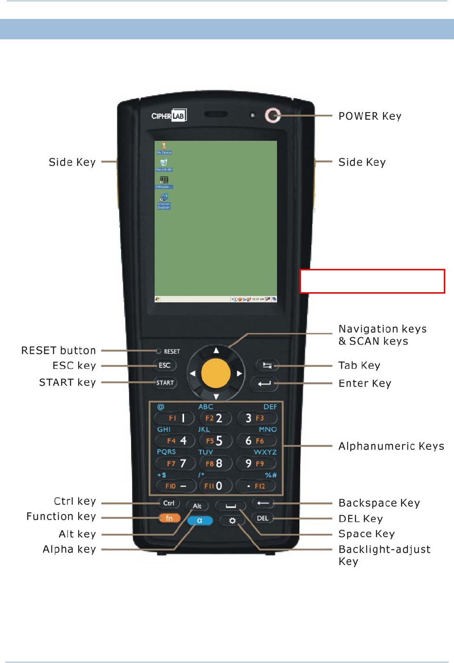
13
Specifications
1.3.2 29-KEY KEYPAD
The 29-key keypad includes alphanumeric, navigation, function keys, and so on. This
keypad is set to numeric mode by default.
Q
V
G
A
Screen + 29-key
Figure 6: 29-key Layout

14
9300 Mobile Compute
r
Reference Manual
ALPHA KEY
This alphanumeric keypad is set to numeric mode by default. The Alpha key serves as a toggle
among numeric, alpha (lower-case alphabetic), and ALPHA (upper-case alphabetic) input modes.
Note: It is not necessary to hold down the [Alpha] key.
The alpha icon will appear on the status bar in a sequence as shown below.
Status Icon Alpha Key Input Mode
N/A Numbers
Press one time Small letters
Press two times Capital letters
Note: If you are using the software keypad via SIP, tap CAP (Caps Lock) to toggle
between upper case and lower case alphabetic modes.

15
Specifications
1.3.3 43-KEY KEYPAD
The 43-key keypad includes numeric, alphabetic, function and other modifier keys, as
well as keys for navigation and assorted characters.
Q
VGA Screen + 43-key
Figure 7: 43-key Layout

16
9300 Mobile Compute
r
Reference Manual
1.3.4 FUNCTION KEY
The [FN] (function) key serves as a modifier key, and the functionality of each key
combination is application-dependent.
1) To enable this modifier key, press [FN] on the keypad. A circular icon of the letter "F"
will appear on the status bar. This modifier key is hold down as long as the icon is
displayed.
2) Now press another key to get the value of key combination (say, press [1] to get the
value of F1). The icon will go off now.
3) To get the value of another key combination modified by the [FN] key, repeat the
above steps.
4) To abort the key modification, press [FN] again, and the icon will go off.
Note: It is not necessary to hold down the [FN] key.
Below is a list of the factory setting for a variety of key combinations.
Key Combination Action
[FN], Move text up one screenful (Page Up)
[FN], Move text down one screenful (Page Down)
[FN], Move to the beginning of screen or document (Home)
[FN], Move to the end of screen or document (End)
[FN], [0] Toggle ON/OFF the backlight of keypad only
([FN], [*@-] for 28-key)
([FN], [.$] for 59-key)
T
urn ON the backlight of LCD and decrease its
luminosity
([FN], [.#$] for 28-key)
([FN], [- ;] for 59-key)
Turn ON the backlight of LCD and increase its
luminosity
Note: Press the [FN] key first, and then press the second key for a specific function.
1.3.5 PROGRAMMABLE KEYS
Depending on the keypad layout, a number of keys are user-definable, such as the
programmable keys. They can be re-defined as another key or to serve as a shortcut key
for launching a specific program. Refer to the Button Assignment Utility.
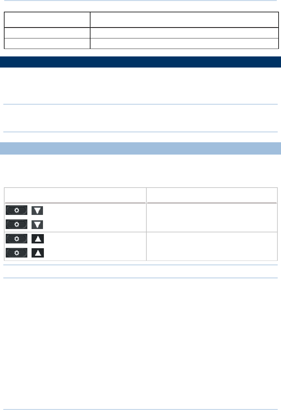
17
Specifications
Programmable Keys Other User-Definable Keys
P1, P2 (28-key) SCAN key and four side triggers on each side of the touch screen
P1, P2, P3 and P4 (59-key) Four side triggers on each side of the touch screen
1.4 TOUCH SCREEN
The mobile computer comes with a 2.8" TFT graphic LCD, 320 by 240 pixels resolution
(QVGA). The LED backlight of screen, which helps ease reading under dim environments,
can be controlled manually and automatically.
Warning: Using backlight while on battery power will substantially reduce battery
power. It is suggested to dim the backlight while working in a well-lit area
or automatically turn off the mobile computer when not in use.
1.4.1 ADJUSTING THE BACKLIGHT
The LED backlight of the screen can be turned on and adjusted decreasingly or
increasingly by the following key combinations. Keep pressing the key combination until
the luminosity is decreased or increased to a desired level.
Key Combination Action
, ([Backlight], [DOWN] for 29-key)
, ([[Backlight], [DOWN] for 43-key)
T
urn ON the backlight of LCD and decrease its
luminosity
, ([[Backlight], [UP] for 29-key)
, ([[Backlight], [UP] for 43-key)
T
urn ON the backlight of LCD and increase its
luminosity
Note: Press the [FN] key first, and then press the second key for adjustment.
Go to Start > Settings > Control Panel and double-tap the Display icon.
1. Tap the Backlight tab. (left below)

18
9300 Mobile Compute
r
Reference Manual
2. Select one or both of the check boxes to automatically turn off the LCD backlight
when using batteries or external power. From the appropriate list, select the
amount of time the device should be idle before the backlight is turned off.
3. Tap the [Advanced] button.
4. In the Settings tab (right above), you can select the luminosity of backlight when
it is set to be automatically turned on by pressing any key or tapping the screen.
Tap, hold, and drag the slider for AC and battery powered respectively. For more
luminosity, move the slider to the right.
1.4.2 RE-CALIBRATING THE SCREEN
This LCD is also a touch screen that can be calibrated through screen alignment.
Go to Start > Settings > Control Panel and double-tap the Stylus icon.
Tap the Calibration tab, and then tap the [Recalibrate] button.

19
Specifications
Warning: DO NOT use any pointed or sharp objects to move against the surface of
the screen.
1.5 NOTIFICATIONS
1.5.1 STATUS LED
The tri-color LED on top is used to provide information on the charging status or wireless
power status. The green LED is also used for "Good Read" while collecting data.
Tasks Green LED Red LED Blue
Charging 9300 --- On ---
Charging done On --- ---
Good Read On --- ---
Bluetooth enabled --- --- On
1.5.2 AUDIO
Buzzer
The mobile computer has a buzzer on the back. It can be programmed for status
feedback. Its frequency and duration are software programmable.
Speaker
The mobile computer is integrated with a mono speaker, which can be used for
playing sounds applied to events in Windows and programs, as well as playing audio
files such as .WAV files. In addition, it can be programmed for status feedback.

20
9300 Mobile Compute
r
Reference Manual
Headset
A headset jack is provided, which is a 2.5 mm DIA stereo earphone jack with
microphone input. Bluetooth headset is also supported.
1.5.3 VIBRATOR
The mobile computer is integrated with a vibrator, which is software programmable for
feedback. This can be helpful when working in noisy environments.
1.6 DATA CAPTURE
1.6.1 BARCODE & RFID READER
A wide variety of scan engines is available for delivering flexibility to meet different
requirements. Depending on the scan engine integrated, the mobile computer is capable
of scanning barcodes of a number of symbologies that are enabled by default while
running 93ReaderConfig.exe. If you need to scan barcodes that are encoded in a
different symbology, enable the symbology first. Refer to Appendixes for details on scan
engine settings.
Appendix I - Scan Engine Settings lists the symbologies and RFID tags supported.
Appendix II - CCD/Laser Scan Engine provides information on the reader settings as
well as symbology settings for the CCD or Laser scan engine.
Appendix III - 2D Scan Engine provides information on the reader settings as well as
symbology settings for the 2D scan engine.
Note: The mobile computer allows the co-existence of one integrated scan engine and
the RFID reader.

21
Specifications
SPECIFICATIONS
PLATFORM, PROCESSOR & MEMORY
Operating System
Microsoft Windows CE 6.0
CPU
Marvell PXA310 at 624 MHz
Memory
ROM 512 MB non-volatile NAND flash memory
RAM 256 MB on-board DDR SDRAM memory
Expansion Slot One SD card slot for inserting memory card, optional
COMMUNICATIONS & DATA CAPTURE
Communications
USB 1.1 Specification
Host port (type-A) / Device port (type-B)
USB via Cradle
USB Client 2.0
WPAN Built-in module for Bluetooth Class 2 connectivity
WLAN Built-in module for 802.11b/g networking
RS232 Support baud rate 9600, 19200, 38400, 57600, 115200, 230k, 640k, and
921k.
Data & Image Capture
Barcode Reader Ordering options include
1D SE 955 Standard Laser
2D Imager

22
9300 Mobile Compute
r
Reference Manual
ELECTRICAL CHARACTERISTICS
Batteries
Main Battery Pack Rechargeable Li-ion battery – 3.7 V, 2700 mAh
Backup Battery Rechargeable Lithium battery – 3.6 V, 15 mAh
Data retention for at least 20 hours
Power Adapter
Input AC 100~240 V, 50/60 Hz
Output DC 5 V, 3 A (Charging & Comm. Cradle)
Working Time (Laser, one scan per 5 seconds)
Batch Mode with backlight 10 hours
Wi-Fi Mode with backlight 8 hours
PHYSICAL CHARACTERISTICS
Color Touch Screen Display
Display 2.8” Transflective TFT-LCD, 65536 colors
Resolution QVGA (320 × 240 pixels)
Keypad
Layout 29 keys for alphanumeric layout
Ordering Option – 43-key layout
Backlight White LED backlight for display and keypad
Notifications
Status LED Two dual color LED – Red / Green and Green / Blue
Audio Integrated with one mono speaker and buzzer
Headset jack –
2.5 mm DIA stereo earphone jack with
microphone input
Bluetooth headset supported
Vibrator 0.45G
Enclosures
Materials Plastic and metal
Dimensions 170 mm (L) 70 mm (W) 40 mm (H)
Weight Approx. 350 g (configuration-dependent)

23
Specifications
ENVIRONMENTAL CHARACTERISTICS
Temperature
Operating -10 °C to 50 °C
Storage -20 °C to 60 °C
Humidity
Operating 10% to 90%, non-condensing
Storage 5% to 95%, non-condensing
Resistance
Impact Resistance 1.5 m, 5 drops per 6 sides
Tumble Test 100 cm, 1000 drops
Splash/Dust Resistance IP 54
Electrostatic Discharge ± 15 kV air discharge, ± 8 kV direct discharge
Regulations
EMC Regulations FCC, IC, CE, C-Tick, MIC, BSMI, NCC, TELEC, SRMC
PROGRAMMING SUPPORT
Development Environment & Tools
Integrated Development
Environment Visual Studio 2005
Visual Studio .NET 2003
eMbedded Visual C++ 4.0 SP4
9300 SDK or Windows CE 6.0 Standard SDK Software Development Kit
System API (static and DLL) for system configuration
ReaderDLL for reader configuration
Software & Utilities
Reader Configuration Utility
Terminal Emulation for VT100/220 or IBM 5250
Application Generator
STREAM Wireless Studio
Web Browser
Third-party software –
Wavelink Avalanche Enabler & Telnet Client
MCL Collection - MCL Client

24
9300 Mobile Compute
r
Reference Manual
ACCESSORIES
Accessory Options
SD Memory Card
Protective Cover
Spare rechargeable battery pack, standard or high capacity pack
4-Slot Battery Charger
Charging & Communication Cradle

25
Appendix I
SCAN ENGINE SETTINGS
The Reader Configuration Utility (93ReaderConfig.exe) allows configuring the
following reader types, depending on the module equipped on your mobile computer:
1D CCD scan engine
1D Laser scan engine
2D scan engine
RFID reader
Options of different reader combination are allowed, such as 1D+RFID and 2D+RFID. For
each combination, both readers can be initialized and ready for scanning at the same
time (dual mode operation). For example, if you press the [SCAN] button while running
the 93ReaderConfig utility on the mobile computer, it will read a barcode in position or an
RFID tag in proximity depending on which one comes first.
Note: (1) You cannot have 1D+2D scan engines installed on the mobile computer
because they are both barcode readers!
(2) You can run only one utility or application at a time to control the reader(s).
For example, while running 93ReaderConfig.exe, you should not run Application
Generator, STREAM Wireless Studio, MIRROR Browser, or any other application
that uses ReaderDLL.
SYMBOLOGIES SUPPORTED
Varying by the scan engine installed, the supported symbologies or tag types are listed
below. For details on configuring associated settings, please refer to each Appendix
separately.
CCD, Laser 2D
Codabar 9 9
Code 11 8 9
Code 93 9 9
Composite Code 8 9
MSI 9 9
Plessey 9 8
Postal Codes 8 9
Telepen 9 8
Code 128 Code 128 9 9
EAN-128 9 9

26
9300 Mobile Compute
r
Reference Manual
ISBT-128 8 9
Code 2 of 5 Industrial 25 (i.e. Discrete 25) 9 9
Interleaved 25 9 9
Matrix 25 9 8
Code 3 of 9 Code 39 9 9
Trioptic Code 39 8 9
Italian Pharmacode (i.e. Code 32) 9 9
French Pharmacode 9 8
EAN/UPC EAN-8 9 9
EAN-13 9 9
Bookland EAN (i.e. ISBN) 9 9
UPC-E0 9 9
UPC-E1 8 9
UPC-A 9 9
RSS RSS-14 9 9
RSS Limited 9 9
RSS Expanded 9 9
2D Symbologies PDF417 8 9
MicroPDF417 8 9
Data Matrix 8 9
Maxicode 8 9
QR Code 8 9

27
Appendix I
Scan Engine Settings
RFID TAGS SUPPORTED
The RFID reader supports read/write operations depending on the tags. The supported
labels include ISO 15693, Icode®, Tag-it®, ISO 14443A, and ISO 14443B.
Currently, the performance of many tags has been confirmed, and the results are listed
below for your reference.
Note: You should study the specifications of RFID tags before use.
TI_RFID Module Version 1.0.A UID Only Read Page Write Page
ISO 14443A Mifare Standard 1K 9 --- ---
Mifare Standard 4K 9 --- ---
Mifare Ultralight 9 --- ---
Mifare DESFire 9 --- ---
Mifare S50 9 --- ---
SLE44R35 9 --- ---
SLE66R35 9 --- ---
ISO 14443B SRIX 4K --- --- ---
SR176 --- --- ---
ISO 15693 ICODE SLI 9 9 9
SRF55V02P 9 9 9
SRF55V02S 9 --- ---
SRF55V10P 9 9 9
TI Tag-it HF-I 9 9 9
ST LRI512 9 --- ---
Tag-it® Tag-it 9 9 9
ICODE®
(Phillips) ICODE --- --- ---

28
9300 Mobile Compute
r
Reference Manual

29
Appendix II
CCD/LASER SCAN ENGINE
The tables below list reader settings as well as symbology settings for the CCD or Laser
scan engine.
READER SETTINGS TABLE
CCD/Laser Description Default
Time-out 3 sec.
1~9 (second) for
93ReaderConfig.exe
0~255 (second) for
programming
Set the maximum time for decoding to continue during a scan attempt. It
applies to the following scan modes only –
Aiming mode
Laser mode
Auto Off mode
Auto Power Off mode
Scan Mode Laser mode
Continuous Mode Non-stop scanning
To decode
the same barcode repeatedly, move away the scan beam
and target it at the barcode for each scanning.
Test Mode Non-stop scanning
Capable of decoding the same barcode repeatedly
Repeat Mode Non-stop scanning
Capable of re-transmitting barcode data if triggering within one second
after a successful decoding
Momentary Mode Hold down the scan trigger to start with scanning.
The scanning won't stop until you release the trigger.
Alternate Mode Press the scan trigger to start with scanning.
The scanning won't stop until you press the trigger again.
Aiming Mode Press the scan trigger to aim at a barcode. Within one second, press the
trigger again to decode the barcode.
The scanning won't stop until (a) a barcode is decoded or (b) the
pre-set timeout expires.
Laser Mode Hold down the scan trigger to start with scanning.
The scanning won't stop until (a) a barcode is read, (b) the preset
timeout expires, or (c) you release the trigger.
Auto Off Mode Press the scan trigger to start with scanning.
The scanning won't stop until (a) a barcode is read or (b) the preset
timeout expires.

30
9300 Mobile Compute
r
Reference Manual
Auto Power Off Mode Press the scan trigger to start with scanning.
The scanning won't stop until the preset timeout expires, and, the
preset timeout period re-counts after each successful decoding.
Read Redundancy None
None No redundancy means one successful decoding will make the reading valid
and induce the "READER Event".
One time, Two times,
or Three times The higher the reading security is (that is, the more redundancy the user
selects), the slower the reading speed gets.
If "Three Times" is selected, it will take a total of four consecutive
successful decodings of the same barcode to make the reading valid.
SYMBOLOGY SETTINGS TABLE
CCD/Laser Description Default
Codabar Enable
Select Start/Stop
Characters If "Transmit Start/Stop Characters" is desired, select one
set:
abcd / abcd
abcd / tn*e
ABCD / ABCD
ABCD / TN*E
abcd / abcd
Transmit Start/Stop
Characters Decide whether to include the start
/
stop characters in the
data being transmitted. No
Code 128 Enable
EAN-128 Enable
Transmit Code ID Decide whether to include Code ID (“]C1”) will be included
in the data being transmitted. No
Industrial 25 (= Discrete 25) Enable
Start/Stop Selection This decides the readability of all 2 of 5 symbology
variants. For example, flight tickets actually use an
Industrial 2 of 5 barcode but with Interleaved 2 of 5
start/stop pattern. In order to read this barcode, the
start/stop pattern selection parameter of
Industrial 2 of 5
should set to "Interleaved 25".
Industrial 25
Verify Checksum Decide whether to verify the checksum. If the checksum is
incorrect, the barcode will not be accepted. No
Transmit Checksum Decide whether to include the checksum in the data being
transmitted. Yes
Select Length One or two fixed lengths
Range 4~127
Interleaved 25 Enable
Start/Stop Selection Refer to Industrial 25. Interleaved
25

31
Appendix II
CCD/Laser Scan Engine
Verify Checksum Decide whether to verify the checksum. If the checksum is
incorrect, the barcode will not be accepted. No
Transmit Checksum Decide whether to include the checksum in the data being
transmitted. Yes
Select Length One or two fixed lengths
Range 4~127
Matrix 25 Enable
Start/Stop Selection Refer to Industrial 25. Matrix 25
Verify Checksum Decide whether to verify the checksum. If the checksum is
incorrect, the barcode will not be accepted. No
Transmit Checksum Decide whether to include the checksum in the data being
transmitted. Yes
Select Length One or two fixed lengths
Range 4~127
French Pharmacode Disable
*Transmit Start/Stop
Character Controlled by the same setting of Code 39. No
Transmit Checksum Decide whether to include the checksum in the data being
transmitted. Yes
Italian Pharmacode (= Code 32) Disable
*Transmit Start/Stop
Character Controlled by the same setting of Code 39. No
Transmit Checksum Decide whether to include the checksum in the data being
transmitted. Yes
Code 39 Enable
Transmit Start/Stop
Character Decide whether to include the start/stop characters "*" in
the data being transmitted. No
Verify Checksum Decide whether to verify the checksum. If the checksum is
incorrect, the barcode will not be accepted. No
Transmit Checksum Decide whether to include the checksum in the data being
transmitted. Yes
Code 39 Full ASCII Code 39 Full ASCII includes all the alphanumeric and
special characters. Disable
Code 93 Enable
MSI Disable
Verify Checksum Select one of the three calculation formulas to verify the
checksum. If the checksum is incorrect, the barcode will
not be accepted.
Single Modulo 10
Double Modulo 10
Modulo 11 & 10
Single Modulo
10

32
9300 Mobile Compute
r
Reference Manual
Transmit Checksum Decide whether to include the checksum in the data being
transmitted.
Last digit not transmitted
Both digits transmitted
Both digits not transmitted
Both digits
transmitted
Select Length One or two fixed lengths
Range 4~127
Negative Barcode Disable
Plessey Disable
Convert to UK Plessey When applied, each occurrence of the character "A" in the
barcode data will be replaced by the character "X". No
Transmit Checksum Decide whether to include the checksum (2 digits) in the
data being transmitted. Yes
Telepen Disable
Original Telepen
(Numeric) The original Telepen includes numeric characters. Yes
AIM Telepen (Full
ASCII) AIM Telepen (Full ASCII) includes all the alphanumeric and
special characters. No
RSS-14 Disable
Transmit Code ID Decide whether to include Code ID (“]e0”) will be included
in the data being transmitted. Yes
Transmit Application
ID Decide whether to include the Application ID
("01") in the
data being transmitted. Yes
Transmit Checksum Decide whether to include the checksum in the data being
transmitted. Yes
RSS Limited Disable
Transmit Code ID Refer to RSS-14. Yes
Transmit Application
ID Refer to RSS-14. Yes
Transmit Checksum Refer to RSS-14. Yes
RSS Expanded Disable
Transmit Code ID Refer to RSS-14. Yes
EAN-8 Enable
Convert to EAN-13 The EAN-8 barcode will be expanded into EAN-13, and the
next processing will follow the settings configured for
EAN-13.
No
Transmit Checksum Decide whether to include the checksum in the data being
transmitted. Yes
Addon 2 / Addon 5 Decide whether to decode EAN-8 with supplementals. No
EAN-13 / UPC-A Enable
ISBN Conversion The EAN-13 barcode starting with 978 and 979 will be
converted to ISBN. No

33
Appendix II
CCD/Laser Scan Engine
ISSN Conversion The EAN-13 barcode starting with 977 will be converted to
ISSN. No
GTIN for EAN-13 The EAN-13 barcode will be expanded into 14-digit Global
Trade Item Number (GTIN). No
Transmit Checksum Decide whether to include the checksum in the data being
transmitted. Yes
Addon 2 / Addon 5 Decide whether to decode EAN-13/UPC-A with
supplementals. No
(UPC-A) Convert to
EAN-13 The UPC-A barcode will be expanded into EAN-13, and the
next processing will follow the settings configured for
EAN-13.
Yes
(UPC-A) Transmit
Checksum Decide whether to include the UPC-A checksum in the data
being transmitted. Yes
(UPC-A) Transmit
System Number Decide whether to include the UPC-A System Number in
the data being transmitted. Yes
UPC-E Enable
Convert to UPC-A The UPC-E barcode will be expanded into UPC-A, and the
next processing will follow the settings configured for
UPC-A.
No
Transmit Checksum Decide whether to include the UPC-E checksum in the data
being transmitted. Yes
Transmit System
Number Decide whether to include the UPC-E System Number in
the data being transmitted. No
Addon 2 / Addon 5 Decide whether to decode UPC-E with supplementals. No
*It cannot read UPC-E1 barcodes!

34
9300 Mobile Compute
r
Reference Manual

35
Appendix III
2D SCAN ENGINE
The tables below list reader settings as well as symbology settings for the 2D scan
engine.
READER SETTINGS TABLE
2D Description Default
Decode Time-out Set the maximum time for decoding to continue during a
scan attempt.
1~9 (second) for 93ReaderConfig.exe – default to 3
5~99 (0.1 second) for programming – default to 30
3 sec.
Focus Mode Select the focus mode to control the working range:
Far Focus – optimized to read at its far position
Near Focus – optimized to read at its near position
Smart Focus –
toggles the focus position after every
frame
Far Focus
Decode Illumination Decide whether to flash illumination on every barcode
capture to aid decoding.
Turn On (Internal LED )
Turn Off
On
Aiming Pattern Decide whether to project the aiming
pattern during
barcode capture.
Turn On
Turn Off
On
Read Redundancy Level 1
Level 1
T
he following barcodes must be successfully read twice before being
decoded:
Barcode Types Code Length
Codabar 8 characters or less
MSI 4 characters or less
Discrete 25 (=Industrial 25) 8 characters or less
Interleaved 25 8 characters or less
Level 2 All barcodes must be successfully read twice before being decoded.
Level 3 All barcodes except for the following barcodes must be successfully read
twice before being decoded.
The following barcodes must be read three times:

36
9300 Mobile Compute
r
Reference Manual
Barcode Types “Excluded” Code Length
Codabar 8 characters or less
MSI 4 characters or less
Discrete 25 (=Industrial 25) 8 characters or less
Interleaved 25 8 characters or less
Level 4 All barcodes must be successfully read three times before being decoded.
Security Level Select a decode security level appropriate for the barcode
quality when reading delta barcodes such as Code 128,
Code 93, UPC/EAN.
Security Level 0 –
This default setting allows the scan
engine to operate in its most aggressive state,
providing sufficient security in decoding most “in-spec”
barcodes.
Security Level 1 –
Select this option if misdecodes
occur. This level should eliminate most misdecodes.
Security Level 2 –
Select this option if Security Level 1
fails to eliminate misdecodes.
Security Level 3 –
Select this option if Security Level 2
also fails to eliminate misdecodes. However, selecting
this option impairs the decoding ability of the scan
engine. If this level of security is necessary, try to
improve the barcode quality.
Level 0
SYMBOLOGY SETTINGS TABLE
2D Description Default
Codabar Enable
CLSI Editing When applied, the CLSI editing strips the start/stop
characters and inserts a space after the first, fifth, and
tenth characters of a 14-character Codabar barcode.
The 14-character barcode length does not include
start/stop characters.
No
NOTIS Editing Decide whether to include the start/stop characters in the
data being transmitted.
NOTIS Editing is to strip the start/stop characters, i.e.
to disable "Transmit Start/Stop Characters".
No
Select Length One or two fixed lengths
Range (1~55) 4~55
Code 128 ---
Code 128 Read standard Code 128 barcodes (=without leading FNC1
character). Enable
UCC/EAN-128 Read UCC/EAN-128 barcodes with leading FNC1 character. Enable
ISBT 128 Read ISBT 128 barcodes. Enable

37
Appendix III 2D Scan Engine
Industrial 25 (= Discrete 25) Enable
Select Length One or two fixed lengths
Range (1~55) 4~55
Interleaved 25 Enable
Convert to EAN-13 Convert a 14-character barcode into EAN-13 if the
following requirements are met:
The barcode must have a leading 0 and a valid EAN-13
check digit.
“Verify Checksum” must be disabled.
No
Verify Checksum Decide whether to verify the checksum. If desired, select
one of the algorithms below. If the checksum is incorrect,
the barcode will not be accepted.
No
USS algorithm
OPCC algorithm
No
Transmit Checksum Decide whether to include the checksum in the data being
transmitted.
"Verify Checksum" must be enabled so that the
checksum can be left out (= "Transmit Checksum"
disabled).
No
Select Length One or two fixed lengths
Range (1~55) 4~55
Code 39 Enable
Convert to Code 32 Convert to Italian Pharmacode. No
Code 32 Prefix Prefix character "A" to Code 32 barcodes. No
Verify Checksum Decide whether to verify the checksum. If the checksum is
incorrect, the barcode will not be accepted. No
Transmit Checksum Decide whether to include the checksum in the data being
transmitted.
"Verify Checksum" must be enabled so that the
checksum can be left out (= "Transmit Checksum"
disabled).
No
Code 39 Full ASCII Code 39 Full ASCII includes all the alphanumeric and
special characters. Disable
Select Length One or two fixed lengths
Range (1~55) 4~55
Trioptic Code 39 Disable
Code 93 Enable
Select Length One or two fixed lengths
Range (1~55) 4~55

38
9300 Mobile Compute
r
Reference Manual
MSI Enable
Verify Checksum If Two Check Digits option is selected, an additional
verification is required to ensure integrity. Select one of
the algorithms below. If the checksum is incorrect, the
barcode will not be accepted.
Check Digit Algorithm
One Check Digit Single Modulo 10
Two Check Digits Mod 10/Mod 11
Mod 10/Mod 10
Single Modulo
10
Transmit Checksum Decide whether to include the checksum in the data being
transmitted. No
Select Length One or two fixed lengths
Range (1~55) 4~55
RSS ---
RSS-14 Enable
RSS Limited Enable
RSS Expanded Enable
Convert RSS to
UPC/EAN
"Convert to UPC/EAN" only applies to RSS-14 and RSS
Limited barcodes not decoded as part of a Composite
barcode.
Convert to EAN-13
Strip the leading "010" from barcodes.
"01" is the Application ID and must be followed by a
single zero (the first digit encoded)
Convert to UPC-A
Strip the leading "0100" from barcodes.
"01" is the Application ID and must
be followed by
two or more zeros (but not six zeros)
No
EAN-8 Enable
Convert to EAN-13 The EAN-8 barcode will be expanded into EAN-13, and the
next processing will follow the settings configured for
EAN-13.
No
Addon 2 / Addon 5 Refer to UPC/EAN Addon setting.
EAN-13 Enable
Bookland EAN (=
ISBN) The EAN-13 barcode starting with 978 will be converted to
ISBN. Yes
Addon 2 / Addon 5 Refer to UPC/EAN Addon setting.
UPC-A Enable
Transmit Checksum Decide whether to include the UPC-A checksum in the data
being transmitted. Yes
Transmit Preamble Decide whether to include the UPC-A preamble System
Number (and Country Code) in the data being transmitted. System
Number
Addon 2 / Addon 5 Refer to UPC/EAN Addon setting.
UPC-E0 Enable

39
Appendix III 2D Scan Engine
Transmit Checksum Decide whether to include the UPC-E0 checksum in the
data being transmitted. Yes
Transmit Preamble Decide whether to include the UPC-E0 preamble System
Number (and Country Code) in the data being transmitted. System
Number
Addon 2 / Addon 5 Refer to UPC/EAN Addon setting.
Convert to UPC-A The UPC-E0 barcode will be expanded into UPC-A, and the
next processing will follow the settings configured for
UPC-A.
No
UPC-E1 Disable
Transmit Checksum Decide whether to include the UPC-E1 checksum in the
data being transmitted. Yes
Transmit Preamble Decide whether to include the UPC-E1 preamble System
Number (and Country Code) in the data being transmitted. System
Number
Addon 2 / Addon 5 Refer to UPC/EAN Addon setting.
Convert to UPC-A The UPC-E1 barcode will be expanded into UPC-A, and the
next processing will follow the settings configured for
UPC-A.
No
UCC Coupon Extended Code Disable
Read UPC-A barcodes starting with digit "5", EAN-13 barcodes starting with digits "99", and
UPC-A/EAN-128 Coupon Codes.
UPC-A, EAN-13, and EAN-128 must be enabled first!
Use “Addon Redundancy” to control auto-discrimination of the EAN-128 (right half) of a coupon
code.
UPC/EAN Addon ---
Addon 2 / Addon 5 Decide whether to decode EAN-8, EAN-13, UPC-E0,
UPC-E1, UPC-A with supplementals.
Ignore Supplementals
Decode Only With Supplementals
Decode With Supplementals (= Auto-discriminate)
Ignore...
Addon Redundancy When "Decode with Supplementals" is applied, decide the
number of times of supplementary decoding the same
barcode that makes a valid reading.
10 times
Code 11 Enable
Verify Checksum Decide whether to verify the checksum. If the checksum is
incorrect, the barcode will not be accepted.
No verification
One Check Digit
Two Check Digits
No
Transmit Checksum Decide whether to include the checksum in the data being
transmitted.
"Verify Checksum" must be enabled so that the
checksum can be left out (= "Transmit Checksum"
disabled).
No

40
9300 Mobile Compute
r
Reference Manual
Select Length One or two fixed lengths
Range (1~55) 4~55
Postal Codes ---
US Postnet Enable
US Planet Enable
Transmit US Postal
Checksum US Postnet or US Planet must be enabled first! Enable
UK Postal Enable
Transmit UK Postal
Checksum UK Postal must be enabled first! Enable
Japan Postal Enable
Australian Postal Enable
Dutch Postal Enable
Composite Codes ---
Composite CC-C Enable
Composite CC-A/B Disable
Composite TLC-39 Disable
UCC/EAN Code 128
Emulation Mode Transmit data as if it was encoded in Code 128 barcodes.
Transmit AIM Code Identifier must be enabled first!
Disable
UPC barcodes can be "linked" with a 2D barcode during
transmission as if they were one barcode. UPC Always
Linked
UPC Composite Mode
UPC Never Linked
Transmit UPC barcodes regardless of whether a 2D
barcode is detected.
UPC Always Linked
Transmit UPC barcodes and the 2D portion. If the 2D
portion is not detected, the UPC barcode will not be
transmitted.
CC-A/B or CC-C must be enabled!
Auto-discriminate UPC Composites
Transmit UPC barcodes as well as the 2D portion if
present.
2D Symbologies ---
PDF417 Enable
MicroPDF417 Disable
MicroPDF417 Code 128
Emulation
T
ransmit data from certain MicroPDF417 barcodes as if it
was encoded in Code 128 barcodes.
Transmit AIM Code Identifier must be enabled first!
Disable

41
Appendix III 2D Scan Engine
When applied, the MicroPDF417 barcodes are transmitted
with one of these prefixes:
The first codeword of MicroPDF417 is 903-907, 912,
914, 915:
The original Code ID "]L3" will be changed to "]C1".
The first codeword of MicroPDF417 is 908 or 909:
The original Code ID "]L4" will be changed to "]C2".
The first codeword of MicroPDF417 is 910 or 911:
The original Code ID "]L5" will be changed to "]C0".
Data Matrix Enable
Maxicode Enable
QR Code Enable
2D Symbologies - Macro PDF ---
Macro PDF is a special feature for concatenating multiple PDF barcodes into one file, known as
Macro PDF417 or Macro MicroPDF417.
Transmit/Decode Mode
Decide how to handle Macro PDF decoding.
Buffer All Symbols / Transmit Macro PDF When
Complete
Transmit all decoded data from an entire Macro PDF
sequence only when the entire sequence is scanned and
decoded. If the decoded data exceeds the limit of 50
symbols, no transmission because the entire sequence
was not scanned!
Transmit Any Symbol in Set / No Particular Order
Transmit data from each Macro PDF symbol as decoded,
regardless of the sequence.
Passthrough All Symbols
Transmit and decode all Macro PDF symbols and
perform no processing. In this mode, the host is
responsible for detecting and parsing the Macro PDF
sequences.
Passthrough
All Symbols
ESC Characters When enabled, it uses the backslash "\" as an Escape
character for systems that can process transmissions
containing special data sequences. It will format special
data according to the Global Label Identifier (GLI)
protocol, which only affects the data portion of a Macro
PDF symbol transmission. The Control Header, if enabled,
is always sent with GLI formatting.
None

42
9300 Mobile Compute
r
Reference Manual
Note: When printing barcodes, keep each Macro PDF sequence separate, as each has a
unique identifier. Do not mix barcodes from several Macro PDF sequences, even if
they encode the same data. When you scan Macro PDF sequences, scan the entire
Macro PDF sequence without interruption!
Image Capture Disable
Image Capture
Illumination Decide whether to flash illumination on every image
capture to aid decoding.
Turn On (Internal LED )
Turn Off
On
Image Capture
Autoexposure Decide whether to manually specify the gain and exposure
time (only recommended for advanced users with difficult
image capture situations).
On
Gain Time Only applies when Image Capture Autoexposure is
disabled.
Gain is a means of amplifying the raw image data
before it is converted into 256 grayscale values.
Increasing the gain increases brightness and contrast,
but also increases noise (undesired electrical
fluctuations in the image) which makes the image less
attractive and/or harder to decode.
Set the manual gain time in the range of 79~127.
100
Exposure Time Only applies when Image Capture Autoexposure is
disabled.
Exposure Time controls the amount of time the CCD is
allowed to collect light, much like the shutter speed for
a camera.
Generally, the brighter the environment, the
lower the exposure time. Increasing the exposure time
past 20 ms in a handheld application increases the risk
of blurring the image due to hand jitter.
Set the manual exposure time to one of the following
values — 5 ms, 10 ms, 15 ms, 20 ms, 25 ms, or 30
ms.
10 ms
Snapshot Aiming
Pattern Decide whether to project the aim pattern while capturing
an image. On
Image Resolution Decide how to alter image resolution before compression.
Multiple pixels are combined to one pixel, resulting in a
smaller image containing the original content with reduced
resolution.
640×480 (Full resolution)
320×240 (Half resolution)
212×160 (1/3 resolution)
160×1420 (1/4 resolution)
640×480
Image Format Decide in which file format the image is saved.
JPEG file format
BMP file format
JPEG

43
Appendix III 2D Scan Engine
Optimized for JPEG
Quality Decide whether JPEG images are optimized for quality.
Cancel the check box so that JPEG images are
optimized for size.
Enable
Select JPEG Quality Set a value from 5 to 100, where “100” represents the
highest quality image. 65
Select JPEG Size Set a value from 5 to 150, which represents the file size in
multiples of 1024 bytes (1K). For example, setting this
value to 8 permits the file size to be as large as 8192
bytes.
40
Bits per Pixel Select the number of significant bits per pixel (BPP) to use
when capturing an image.
1 bit per pixel (for black and white images)
4 BPP (to assign 1 of 16 levels of grey to each pixel)
8 BPP (to assign 1 of 256 levels of grey to each pixel)
8
Note: (1) For JPEG files, these BPP settings are ignored for it always uses 8 bits per pixel!
(2) When the image capture feature is enabled, press the [SCAN] button and it will
capture an image instead of reading a barcode.
Miscellaneous Options ---
Transmit Code ID Decide whether to include AIM Code ID in the beginning of
data. Each AIM Code ID contains the three-character string
“]cm” –
] = Flag Character (ASCII 93)
c = Code Character (see below)
m = Modifier Character (see below)
Disable

44
9300 Mobile Compute
r
Reference Manual
AIM CODE ID – CODE CHARACTERS
Code Character Code Type
A Code 39, Code 39 Full ASCII, Code 32
C Code 128, Coupon (Code 128 portion)
d Data Matrix
E UPC/EAN, Coupon (UPC portion)
e RSS Family
F Codabar
G Code 93
H Code 11
I Interleaved 25
L PDF417, Macro PDF417, Micro PDF417
M MSI
Q QR Code
S Discrete 25, IATA 2 of 5
U Maxicode
X Code 39 Trioptic, Bookland EAN, US Postnet, US Planet, UK Postal, Japan
Postal, Australian Postal, Dutch Postal
AIM CODE ID – MODIFIER CHARACTERS
Code Type Option Value Option
0 No check character or Full ASCII processing.
1 Checksum has been verified.
3 Checksum has been verified and stripped.
4 Full ASCII conversion has been performed.
5 Result of option values 1 and 4.
Code 39
7 Result of option values 3 and 4.
0 Standard data packet. No Function Code 1“FNC1” in the first
character position.
1 Function Code 1“FNC1” in the first character position.
Code 128
2 Function Code 1“FNC1” in the second character position.
0 No check digit processing.
1 Checksum has been verified.
Interleaved 25
3 Checksum has been verified and stripped.
Codabar 0 No check digit processing.
Code 93 0 Always transmit 0.

45
Appendix III 2D Scan Engine
0 Modulo 10 check digit verified and transmitted. MSI
1 Modulo 10 check digit verified but not transmitted.
Discrete 25 0 Always transmit 0.
0 Standard data packet in full EAN country code format, which
is 13 digits for UPC-A and UPC-E (not including
supplemental data).
3 Standard data packet with two-digit or five-digit
supplemental data.
4 EAN-8 data packet.
UPC/EAN
A UPC-A with Addon 2 barcode, 012345678905-10, is transmitted to the host
as a 18-character string, ]E3001234567890510.
Bookland EAN 0 Always transmit 0.
Trioptic Code 39 0 Always transmit 0.
0 Single check digit (has been verified.)
1 Two check digits (has been verified.)
Code 11
3 Checksum has been verified but not transmitted.
0 Always transmit 0. RSS Family
RSS-14 and RSS Limited will be transmitted with an Application Identifier
“01”. For example, an RSS-14 barcode, 100123456788902, is transmitted
as ]e001100123456788902.
Note: In UCC/EAN-128 emulation mode, RSS is transmitted using Code 128 rules (i.e.
“]C1”).
Native mode transmission
0 Standard data packet
1 Data packet containing the data following an encoded
symbol separator character.
2 Data packet containing the data following an escape
mechanism character. The data packet does not support the
ECI protocol.
3 Data packet containing the data following an escape
mechanism character. The data packet supports the ECI
protocol.
UCC/EAN-128 emulation
EAN.UCC
Composites (RSS,
UCC/EAN-128, 2D
portion of UPC
composite)
1 Data packet is a UCC/EAN-128 barcode (i.e. data is
preceded with “]JC1”).
Note: UPC portion of composite is transmitted using UPC rules.
PDF417,
Micro PDF417
0 Scan engine is set to conform to protocol defined in 1994
PDF417 symbology specifications.
When this option is transmitted, the receiver cannot
reliably determine whether ECIs have been invoked or
whether data byte 92DEC has been doubled in

46
9300 Mobile Compute
r
Reference Manual
transmission.
1 Scan engine is set to follow the ECI protocol (Extended
Channel Interpretation). All data characters 92DEC are
doubled.
2 Scan engine is set for Basic Channel operation (no escape
character transmission protocol). Data characters 92DEC
are not doubled.
When decoders are set to this mode, unbuffered Macro
symbols and symbols requiring the decoder to convey
ECI escape sequences cannot be transmitted.
3 The barcode contains a UCC/EAN-128 symbol, and the first
codeword is 903-907, 912, 914, 915.
4 The barcode contains a UCC/EAN-128 symbol, and the first
codeword is in the range 908-909.
5 The barcode contains a UCC/EAN-128 symbol, and the first
codeword is in the range 910-911.
A PDF417 barcode, ABCD, with no transmission protocol enabled, is
transmitted as ]L2ABCD.
0 ECC 000-140, not supported.
1 ECC 200.
2 ECC 200, FNC1 in first or fifth position.
3 ECC 200, FNC1 in second or sixth position.
4 ECC 200, ECI protocol implemented.
5 ECC 200, FNC1 in first or fifth position, ECI protocol
implemented.
Data Matrix
6 ECC 200, FNC1 in second or sixth position, ECI protocol
implemented.
0 Mode 4 or 5
1 Mode 2 or 3
2 Mode 4 or 5, ECI protocol implemented.
Maxicode
3 Mode 2 or 3, ECI protocol implemented in secondary
message.
0 Model 1
1 Model 2, ECI protocol not implemented.
2 Model 2, ECI protocol implemented.
3 Model 2, ECI protocol not implemented, FNC1 implied in
first position.
4 Model 2, ECI protocol implemented, FNC1 implied in first
position.
5 Model 2, ECI protocol not implemented, FNC1 implied in
second position.
QR Code
6 Model 2, ECI protocol implemented, FNC1 implied in second
position

47
Appendix III 2D Scan Engine