CipherLab 9500CE1 Terminal User Manual
CipherLab Co., Ltd. Terminal
UserManual.wiki
>
CipherLab
>
9500CE1 User Manual
User manual
Navigation menu
Upload a User Manual
Namespaces
Wiki Guide
HTML
PDF
Info
Views
User Manual
Discussion / Help
Navigation

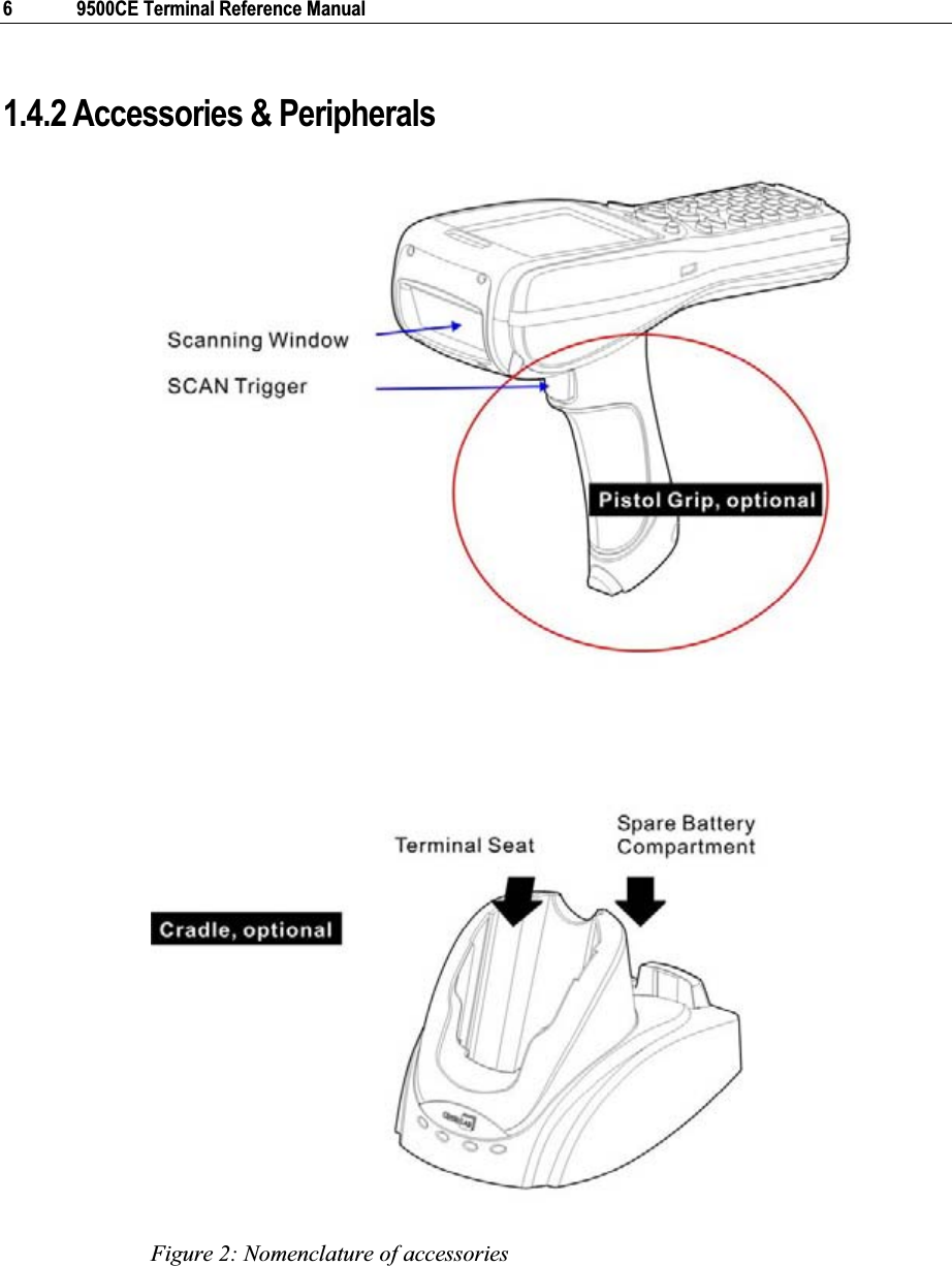
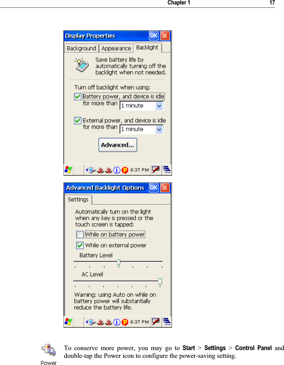
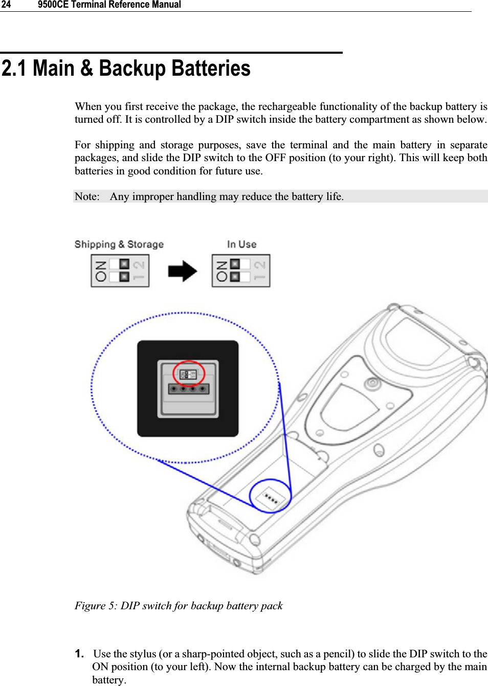
![VFor any portable device, power management is a critical issue especially when you are on the road. Below are some tips to help you save battery power. To speed up charging the terminal, turn off the terminal and seat it in the cradle. Bring a second battery pack on the road. Stop wireless connectivity, Bluetooth, 802.11b/g that is not in use. The power to the wireless modules, 802.11b/g, is controlled by PwrMg.exe (the Wireless Power Manager), which can be found on the taskbar ( ).To save power, go to Start > Settings > Control Panel for related settings: Double-tap the Display icon 1. Tap the Backlight tab. 2. Select one or both of the check boxes to automatically turn off the LCD backlight when using batteries or external power. From the appropriate list, select the amount of time the device should be idle before the backlight is turned off. 3. Then, tap the [Advanced] button to view more backlight options. 4. In the Settings tab, you can dim the LCD backlight when in a well-lit working area for AC and battery powered respectively. Double-tap the Power icon 1. Tap the Schemes tab. 2. Select the desired power scheme and options for suspending operation when not in use. Power Management](https://usermanual.wiki/CipherLab/9500CE1/User-Guide-921373-Page-5.png)
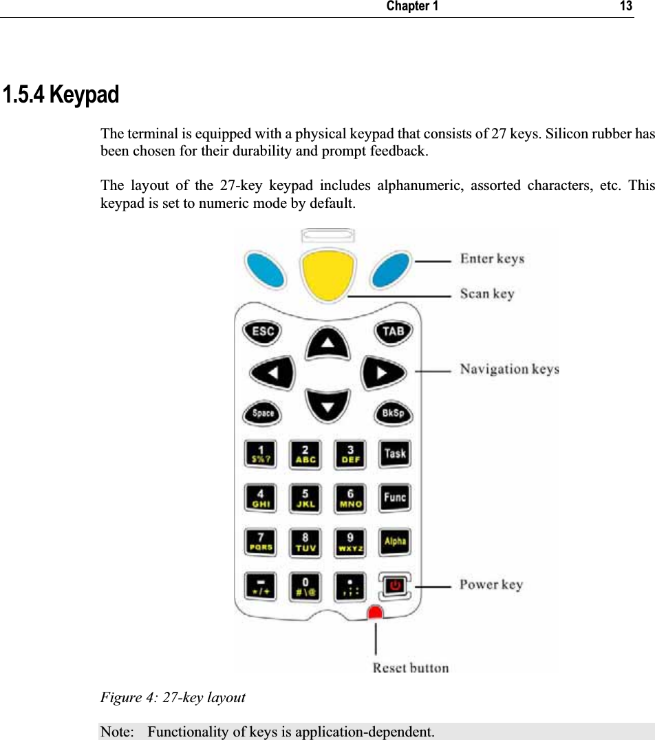
![14 9500CE Terminal Reference Manual Keypad Settings first, and then The LED backlight of keypad is turned off by default. It can be toggled ON/OFF by the key combination: [Func] + [0]. Start > Settings > Control Panel and double-tap the Keyboard icon The Character Repeat functionality is enabled by default. You may cancel the check box to disable it. When enabled, tap, hold, and drag the slider for a desired Repeat Delay and Repeat Rate. Warning: Using backlight while on battery power will substantially reduce battery life. It is suggested to turn on the keypad backlight while working in a dark area.Task KeyThe [Task] key on the keypad is set to trigger Windows Explorer.To launch Windows Explorer, press on the keypad. Alpha KeyThis alphanumeric keypad is set to numeric mode by default. The Alpha key serves as a toggle among numeric, alpha (lower-case alphabetic), and ALPHA (upper-case alphabetic) modes. Note: It is not necessary to hold down the [Alpha] key. The alpha icon will appear on the status bar in a sequence as shown below. Status Icon Alpha Key Input Mode N/A Numbers Press one time Small letters Press two times Capital letters Note: If you are using the software keypad via SIP, tap CAP (Caps Lock) to toggle between upper case and lower case alphabetic modes.](https://usermanual.wiki/CipherLab/9500CE1/User-Guide-921373-Page-22.png)
![Chapter 1 15 Func KeyThe [Func] (function) key serves as a modifier key. 1. To enable this modifier key, press on the keypad. A circular icon of the letter "F" will appear on the status bar. This modifier key is hold down as long as the icon is displayed. 2. Now press another key to get the value of key combination (say, press [1] to get the value of F1). The icon will go off now. 3. To get the value of another key combination modified by the [Func] key, repeat the above steps. 4. To abort the key modification, press again, and the icon will go off. Note: It is not necessary to hold down the [Func] key. The functionality of each key combination is application-dependent. Below is a list of the factory setting for a variety of key combinations. Press first, and then press one of the following keys for a specific function: Key Combination Action PgUp (red-coded): move text up one screenful PgDn (red-coded): move text down one screenful Home (red-coded): move to the beginning of screen or document End (red-coded): move to the end of screen or document Toggle ON/OFF the backlight of keypad only Turn ON the backlight of LCD and decrease its luminosity Turn ON the backlight of LCD and increase its luminosity](https://usermanual.wiki/CipherLab/9500CE1/User-Guide-921373-Page-23.png)
![16 9500CE Terminal Reference Manual 1.5.5 LCD The terminal comes with a 3.5” TFT graphic LCD, 240 by 320 pixels resolutions. The LED backlight of screen, which helps ease reading under dim environments, can be controlled manually and automatically. Warning: Using backlight while on battery power will substantially reduce battery life. It is suggested to dim the backlight while working in a well-lit area or automatically turn off the terminal when not in use. LCD Settings first, and then The LED backlight of the screen can be turned on and adjusted decreasingly by the key combination: [Func] + [–]. It is not necessary to hold down the [Func] key; keep pressing the [–] key until the luminosity is decreased to a desired level. first, and then The LED backlight of the screen can be turned on and adjusted increasingly by the key combination: [Func] + [•].It is not necessary to hold down the [Func] key; keep pressing the [•] key until the luminosity is increased to a desired level. Display PropertiesStart > Settings > Control Panel and double-tap the Display icon 1. Tap the Backlight tab. (Left below) 2. Select one or both of the check boxes to automatically turn off the LCD backlight when using batteries or external power. From the appropriate list, select the amount of time the device should be idle before the backlight is turned off. 3. Then, tap the [Advanced] button. (Right below) 4. In the Settings tab, you can select the luminosity of backlight when it is set to be automatically turned on by pressing any key or tapping the screen. Tap, hold, and drag the slider for AC and battery powered respectively. For more luminosity, move the slider to the right.](https://usermanual.wiki/CipherLab/9500CE1/User-Guide-921373-Page-24.png)
![18 9500CE Terminal Reference Manual Stylus PropertiesThis LCD is also a touch screen that can be calibrated through screen alignment. Warning: DO NOT use any pointed or sharp objects to move against the surface of the screen. Start > Settings > Control Panel and double-tap the Stylus icon 1. Tap the Calibration tab. 2. Tap the [Recalibrate] button.](https://usermanual.wiki/CipherLab/9500CE1/User-Guide-921373-Page-26.png)
![Chapter 1 19 1.5.6 Status LED The tri-color LED on top of the [Scan] button is used to provide information on status of battery charging or Bluetooth connection. Tasks Green LED Red LED Green & Red Blue Low battery --- Flashing --- --- Terminal charging --- On --- --- Charging done On --- --- --- Charging error --- --- Flashing --- Bluetooth connection enabled --- --- --- On 1.5.7 Speaker The speaker, a low power transducer type, can be used for playing sounds applied to events in Windows and programs, as well as playing audio files such as .WAV files. In addition, it can be programmed for status feedback. 1.5.8 Vibrator The terminal is integrated with a vibrator, which is software programmable for feedback. This can be helpful when working in noisy environments.](https://usermanual.wiki/CipherLab/9500CE1/User-Guide-921373-Page-27.png)
![31This chapter mainly describes the basic skills to work with the 9500CE Terminal terminal. The add-on utilities for applications regarding data collection, processing, and transmission, are introduced in the following chapters. The 9500CE Terminal terminal is specifically designed for real-time data collection in the Windows CE 5.0 environment. It won't take long for any Windows user to get familiarized with it. Keep these two basic skills in mind and explore this Windows CE device at ease. Double-tap an item to select it. Tap and hold an item to see a menu that enables tasks, such as cut, copy, rename, delete, etc. Tap and drag to select multiple items. To close an active window, a dialog box, or a running application, tap or when it is available on the toolbar. If the Close button is not displayed, press [ESC] on the physical keypad to exit. To save current settings and exit, tap when it is available on the toolbar. CHAPTER 3Windows CE Basics](https://usermanual.wiki/CipherLab/9500CE1/User-Guide-921373-Page-39.png)
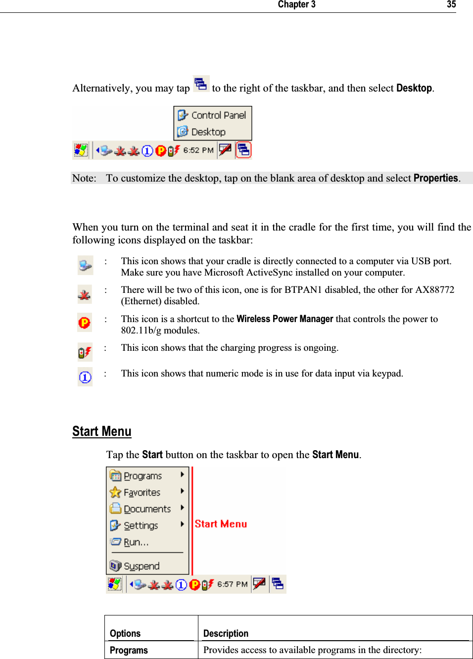
![34 9500CE Terminal Reference Manual 3.1.2 Turn On/Off Like your PDA, Pocket PC and most handheld devices, the 9500CE Terminal terminal functions when it is turned on. This is because the Windows CE operating system eliminates the booting process and runs continuously. Turn On (= Resume from Suspend) To turn on the terminal, simply press the [Power] key. Turn Off (= Suspend) To turn off the terminal, press the [Power] key again, or select Suspend from the Start Menu.The system is now ready for use but not in use. This is referred to as Suspend mode or Standby mode. It means the system is in power-saving status and waiting for user interference. Warning: To save battery power, it is suggested that the terminal is set to be automatically turned off when not in use. Refer to the Power Managementsection for more information about saving power. 3.1.3 Desktop Window The desktop appears when the terminal is turned on (left below). Tap and hold on the blank area to manage or configure the desktop (right below).](https://usermanual.wiki/CipherLab/9500CE1/User-Guide-921373-Page-42.png)
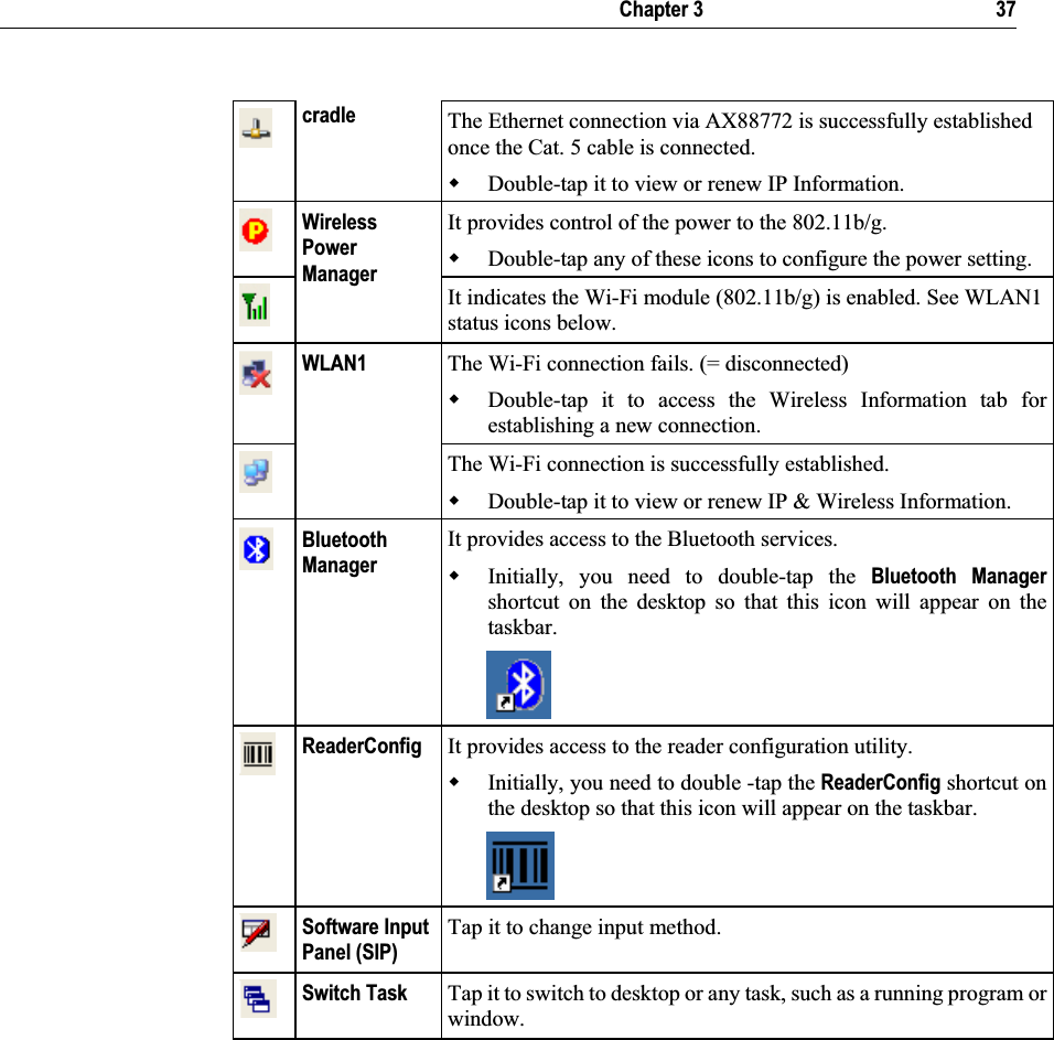
![36 9500CE Terminal Reference Manual \Windows\Programs Favorites Provides access to your favorites in the directory: \Windows\Favorites Documents Provides access to recent opened documents in the directory: \Windows\Recent Settings Provides access to Control Panel Network and Dial-up Connections Taskbar and Start Menu Run… Runs a program or application. Suspend Enters the Suspend mode. Note: To configure the Start menu and taskbar, go to Start > Settings and select Taskbar and Start Menu.TaskbarThe taskbar is at the bottom of the screen for displaying the Start button, up to 6 status icons for various connections or programs, SIP button, Switch Task button, etc.Note: To configure different connections, go to Start > Settings and select Network and Dial-up Connections.Icons Description Connected via USBThe USB connection for ActiveSync operation is successfully established. Double-tap it to view status. Tap [Disconnect] if necessary. The Bluetooth PAN connection fails. (= disconnected) BTPAN1 The Bluetooth PAN connection is successfully established through the Bluetooth Manager utility. Double-tap it to view or renew IP Information. Ethernet via The Ethernet connection via AX88772 fails. (= disconnected)](https://usermanual.wiki/CipherLab/9500CE1/User-Guide-921373-Page-44.png)
![Chapter 3 39 3.2 System Reset Reset the 9500CE Terminal terminal when it stops responding to input. Soft reset: Simply press the [Reset] button. Hard reset: Press the [Reset] button and the [Power] key at the same time. Warning: Never perform a hard reset unless a soft reset cannot solve your problems. 3.2.1 Soft Reset A soft reset, also known as a warm boot, will restart the terminal and keep all the saved files. To perform a soft reset, use the stylus to press the [Reset] button. During operation, the removal of battery pack will start a soft reset too. Warning: Data loss may occur when files are not properly closed before a soft reset. 3.2.2 Hard Reset A hard reset, also known as a cold boot, will restart the terminal too. However, it performs a full restore of the terminal to its factory settings and initializes SDRAM. To perform a hard reset, press the [Power] key and [Reset] button at the same time. Data and program files stored in SDRAM will be erased after a hard reset. But you can restore data that is previously synchronized with your computer by performing an ActiveSync operation. Warning: Only the files stored in the Flash File System are retained during a hard reset.](https://usermanual.wiki/CipherLab/9500CE1/User-Guide-921373-Page-47.png)
![40 9500CE Terminal Reference Manual 3.3 Firmware Update Firmware update should be performed with great caution because everything on the terminal will be erased. Backup user-installed applications and files to your computer first. The firmware update utility is available on the CD-ROM. To re-install or upgrade the operating system (image file) on your terminal, run the installer “AP.exe” from the CD-ROM. It will create a shortcut of the program “DLDR.exe” on the desktop of your computer. 1. Install Microsoft ActiveSync on your computer. Refer to section 3.4 for initial ActiveSync operation. Then, disable the ActiveSync operation as shown below. 2. Run the installer “AP.exe” from the CD-ROM. 3. Perform a hardware reset on the 9500CE Terminal terminal. 4. For the terminal to enter the “Download” mode, press [Space] + [8] + [Power] simultaneously in three seconds. 5. Seat the terminal in the cradle. 6. Run the Image Download program (DLDR.exe) on your computer.](https://usermanual.wiki/CipherLab/9500CE1/User-Guide-921373-Page-48.png)
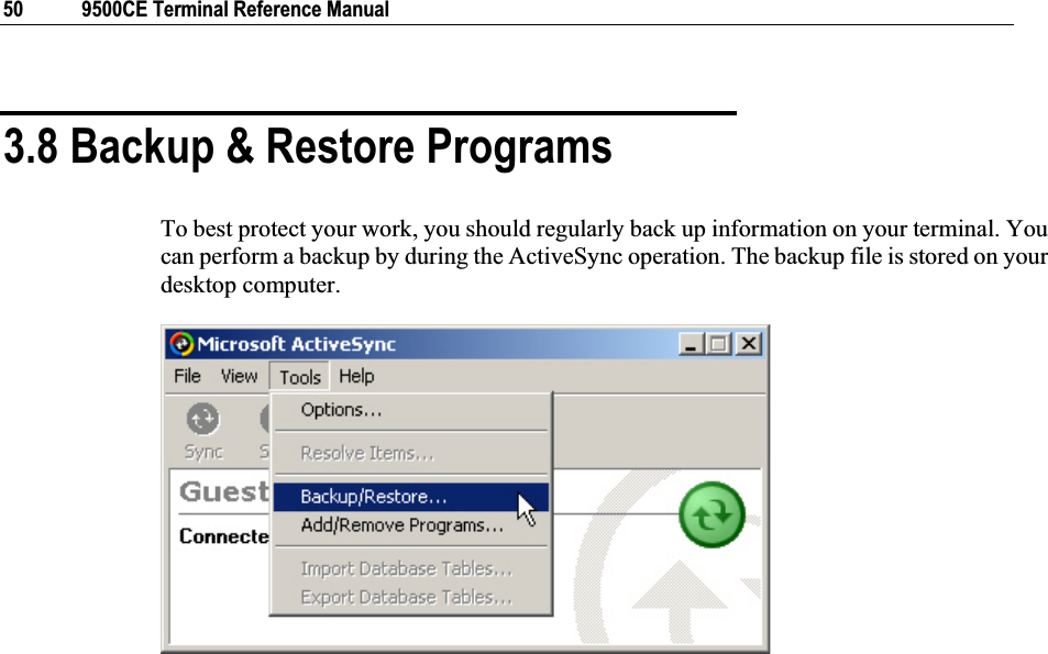
![Chapter 3 41 7. Press [Enter] on the terminal to start image update. It will take approximately 5 minutes to update the image. A message will be displayed on the terminal to indicate the firmware update is completed successfully. 8. Perform a hardware reset on the terminal again. Warning: Do not press any key on the terminal while updating OS image. Once firmware update is completed, you cannot reload any older image. 3.4 ActiveSync with a Computer ActiveSync is used to synchronize information between the terminal and PC, to install programs on the terminal, and to backup and restore the terminal. The Microsoft ActiveSync program has to be installed on your desktop computer first. To download the up-to-date version of the program, you may need to go to Microsoft's official web site for Windows Mobile devices as shown below. http://www.microsoft.com/windowsmobile/default.mspxAfter downloading and installation, run the program. For detailed information on the program, you may click the Help menu, and then select the Microsoft ActiveSync Help. Note: We recommend that you have ActiveSync 3.7.1 installed on your computer because ActiveSync 4.x does not officially support Windows CE 5.0 devices. 1. Follow these instructions for initial ActiveSync operation: Connect the USB cable from the cradle’s USB Client port ( ) to your computer. Connect the power cable from the cradle to a nearby power outlet. Turn on the 9500CE Terminal terminal and seat it in the cradle. 2. Your computer will automatically detect the USB device. Click [OK] when the connection is established. 3. Select which partnership to set up. If you want to synchronize data between 9500CE Terminal and your computer, select Standard Partnership; otherwise, select Guest Partnership. 4. Wait a few seconds for 9500CE Terminal to get connected (and synchronized if a Standard Partnership is selected).](https://usermanual.wiki/CipherLab/9500CE1/User-Guide-921373-Page-49.png)
![42 9500CE Terminal Reference Manual 3.5 Quick Launch a Program Tap the Start button to view the Start Menu. To quick launch a program, tap it from the Programs folder. Note: Alternatively, you may tap Start and select Run to run a specific program or open a document. To add a new program or subfolder to the Programs folder, you can either use Windows Explorer or ActiveSync.Windows Explorer: to move the program by [Copy] and [Paste Shortcut]. ActiveSync on the desktop computer: to create a shortcut to the program, and place the shortcut in the Programs folder. Warning: To avoid making any changes to the program configurations by accident, we recommend you to use [Copy] and [Paste Shortcut] rather than [Cut] and [Paste]. 3.5.1 Add a Program If you wish to quick launch a new program, add it to the Programs folder: MyDevice\Windows\ProgramsUsing Windows Explorer1. Go to Start > Programs, and select Windows Explorer. Alternatively, you can press the [Task] key on the keypad to launch Windows Explorer.2. Navigate through file folders to find the program you desire.](https://usermanual.wiki/CipherLab/9500CE1/User-Guide-921373-Page-50.png)
![Chapter 3 43 3. Tap and hold the program, and then tap [Copy] on the pop-up menu. 4. Navigate to the Programs folder (My Device\Windows\Programs). 5. Tap and hold anywhere blank on the screen. Then tap [Paste Shortcut] on the pop-up menu. The new program will be added to the Programs folder. 6. Go to Start > Programs and the new program will appear now.](https://usermanual.wiki/CipherLab/9500CE1/User-Guide-921373-Page-51.png)
![44 9500CE Terminal Reference Manual Using ActiveSync on PC1. When connected, open the Microsoft ActiveSync window on your desktop computer. 2. Click the Explorer button from the toolbar. 3. Navigate through file folders to find the program you desire. 4. Right-click the program, and then select [Create Shortcut] on the pop-up menu. 5. Right-click the shortcut, and then select [Cut] on the pop-up menu. 6. Navigate to the Programs folder (My Device\Windows\Programs). 7. Right-click anywhere blank on the window. Then select [Paste] on the pop-up menu. The new program will be added to the Programs folder. 8. On the terminal, go to Start > Programs and the new program will appear now. Note: [Create Shortcut], [Cut], and [Paste]: The same result can be performed by [Copy] and [Paste Shortcut].](https://usermanual.wiki/CipherLab/9500CE1/User-Guide-921373-Page-52.png)
![Chapter 3 45 3.5.2 Add a Subfolder Using Windows Explorer1. Go to Start > Programs, and select Windows Explorer. Alternatively, you can press the [Task] key on the keypad to launch Windows Explorer.2. Navigate through file folders to find where you wish to create a new folder. 3. Right-click anywhere blank on the window, and select [New Folder] from the pop-up menu. A subfolder will be created. Using ActiveSync on PC1. When connected, open the Microsoft ActiveSync window on your desktop computer. 2. Click the Explorer button from the toolbar. 3. Navigate to the target folder where you wish to create a new folder. 4. Right-click anywhere blank on the window, and select [New Folder] from the pop-up menu. A subfolder will be created.](https://usermanual.wiki/CipherLab/9500CE1/User-Guide-921373-Page-53.png)
![46 9500CE Terminal Reference Manual 3.5.3 Exit a Program In general, the system manages memory automatically, and there is no need to exit a program in order to open another or to conserve memory. However, random access memory (SDRAM) may be used up when running too many programs. As a result, it will slow down the operation or cause program errors. In that case, you should stop one or more running programs to free memory. In order to use memory in a more efficient way, you are recommended to exit a program when it is not desired any longer. Warning: Always remember to save data or settings before you exit a program. To close an active window, a dialog box, or a running application, tap or when it is available on the toolbar. If the Close button is not displayed, press [ESC] on the physical keypad to exit. Note: Some programs, such as the Bluetooth Manager, may create an associated icon on the taskbar. You may tap the icon and select [Exit] from the pop-up menu. To save current settings and exit, tap when it is available on the toolbar. 3.5.4 Switch between Programs Tap to the right of the taskbar, and then select a running program.](https://usermanual.wiki/CipherLab/9500CE1/User-Guide-921373-Page-54.png)
![Chapter 3 47 3.6 Install a New Program 3.6.1 Add/Remove Programs To install a program that is designed to be used on a mobile device running Windows CE, you may click [Add/Remove Programs] from the Tools Menu. 3.6.2 Copy & Paste Alternatively, you may install a new program manually. 1. When connected, open the Microsoft ActiveSync window on your desktop computer. 2. Click the Explorer button from the toolbar. 3. Navigate to the target folder, e.g. the Programs folder, depending on where you wish to access the program. 4. Navigate through file folders on your computer to find the new program. 5. Right-click the program and select [copy] on the pop-up menu. 6. Back to the target folder in step 3. Right-click anywhere blank and select [Paste] on the pop-up menu. 7. On the terminal, go to Start > Programs and the new program will appear.](https://usermanual.wiki/CipherLab/9500CE1/User-Guide-921373-Page-55.png)
![48 9500CE Terminal Reference Manual 3.7 Uninstall a Program If a user program is no longer desired, you may remove it from the system. 3.7.1 ActiveSync: Add/Remove Programs To uninstall a program that is designed to be used on a mobile device running Windows CE, you may click [Add/Remove Programs] from the Tools Menu. 3.7.2 Control Panel > Remove Programs Alternatively, you may uninstall a new program manually. 1. Go to Start > Settings > Control Panel, and double-tap the Remove Programs icon.2. Tap the name of the program that you want to delete. 3. Tap [Remove]. 4. Tap [Yes] to uninstall the program.](https://usermanual.wiki/CipherLab/9500CE1/User-Guide-921373-Page-56.png)
![Chapter 3 49 Note: If the program does not appear in the list of installed programs, you may use Windows Explorer to locate it. Tap and hold the program, and select [Delete].](https://usermanual.wiki/CipherLab/9500CE1/User-Guide-921373-Page-57.png)
![52 9500CE Terminal Reference Manual Items Description In the [Accessibility] dialog box, you may use these options to customize the way an external keyboard, display, or mouse functions. Many of these features are useful to people without disabilities Keyboard tab: Select StickyKeys to enable simultaneous keystrokes while pressing one key at a time; select ToggleKeys to emit sounds when certain locking keys are pressed. Sound tab: Select SoundSentry to provide visual warnings for system sounds. Display tab: Select High Contrast to improve screen contrast with alternative colors. Mouse tab: Select MouseKeys to enable the keyboard to perform mouse functions General tab: Select Automatic Reset if you wish to turn off accessibility features after a specific period of time; select Notification if you wish to hear a sound when turning a feature on or off. In the [Certificates] dialog box, you may view or modify digital certificates that some application use to establish trust for secure connections. In the [Date/Time] dialog box, you may change date, time, and time zone settings. In the [Display Properties] dialog box, Background tab: Select an image for the background. Appearance tab: Select a desired color scheme for windows, dialog boxes, and items. Backlight tab: Specify for how long the terminal is idle and then the backlight will be automatically turned off while on battery power and external power (in the charging cradle) respectively. Tap the [Advanced] button to move the slider and adjust the brightness of the LCD backlight when it is set to be automatically turned on once a key is pressed or you tap the touch screen. In the [Input Panel Properties] dialog box, you may configure how the Soft Input Panel (SIP) works. In the [Internet Options] dialog box, you may configure how the terminal connects to the Internet. Connect an external keyboard to the cradle via the USB Host port. In the [Keyboard Properties] dialog box, you may configure settings for character repeat.](https://usermanual.wiki/CipherLab/9500CE1/User-Guide-921373-Page-60.png)
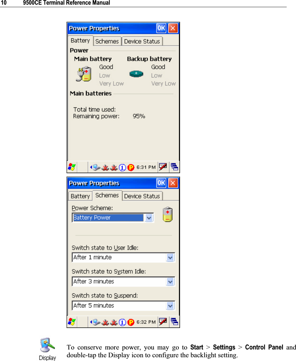
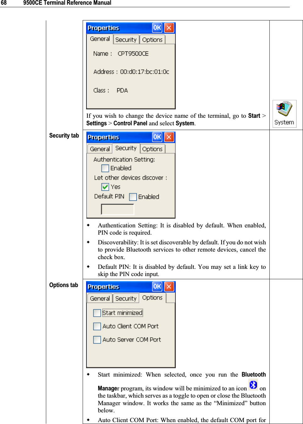
![Chapter 4 53 Connect a mouse to the cradle via the USB Host port. In the [Mouse Properties] dialog box, you may configure and test your double-click settings. In the [Network and Dial-up Connections] window, you may configure settings for the terminal connects to a network directly or through a modem. Alternatively, you may tap Start > Settings > Network and Dial-up Connections.USB Connection (via USB client port on the cradle) AX88772 (via Ethernet port on the cradle) WLAN (via 802.11b/g) BTPAN (via Bluetooth) In the [Owner Properties] dialog box, Identification/Notes tab: Enter your contact information or notes. Network ID tab: Enter the user name, password, and domain name used to log on to the remote network. In the [Password Properties] dialog box, you may apply password protection to limit access to the terminal. In the [PC Connection Properties] dialog box, you may disable the direct connection between the terminal and a computer. By default, the terminal is enabled to directly connect to a computer via the cradle’s USB port. Alternatively, you may tap Start > Settings > Network and Dial-up Connections and select USB Connection. In the [Power Properties] dialog box, Battery tab: You may view the current status of main and backup batteries. Schemes tab: You may configure the power scheme and switching. Device Status tab: You may view the devices that are consuming power. In the [Regional and Language Settings] dialog box, Region tab: You may customize the appearance and formatting to your geographic region. Language tab: By default, it is set to English (United States). Input tab: By default, it is set to English (United States)-US. In the [Remove Programs] dialog box, you may remove any program that is installed earlier. In the [Stylus Properties] dialog box, Double-Tap tab: You may configure and test your double-tap settings. Calibration tab: You may need to re-calibrate the touch screen if it is not responding properly to your taps.](https://usermanual.wiki/CipherLab/9500CE1/User-Guide-921373-Page-61.png)
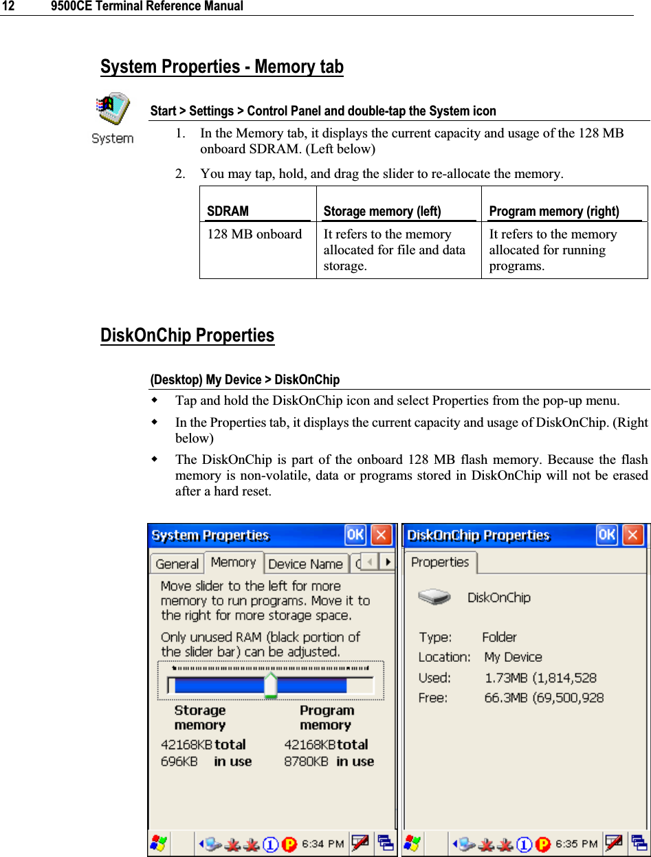
![54 9500CE Terminal Reference Manual In the [System Properties] dialog box, General tab: You may view the system information. Memory tab: You may move the slider and adjust the SDRAM allocation. Device Name tab: You may enter a name and description for identifying the terminal. Copyrights tab: You may view the important statements on copyrights. In the [Volume & Sounds Properties] dialog box, Volume tab: You may move the slider and adjust the volume and select to play sounds for Events, Applications or Notifications. Sounds tab: You may configure sounds for different Windows events. 4.2 Connections There are two ways to access the connections settings: Go to Start > Settings > Control Panel and double-tap the Network and Dial-up Connections icon. Go to Start > Settings > Network and Dial-up Connections.](https://usermanual.wiki/CipherLab/9500CE1/User-Guide-921373-Page-62.png)
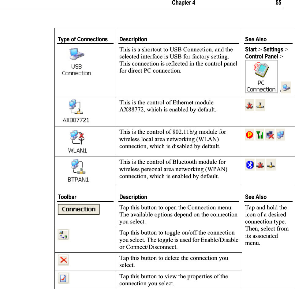
![56 9500CE Terminal Reference Manual 4.2.1 USB Connection Tap and hold on “USB Connection”. Most options can be found in the Connection menu on the toolbar as well. When you select [Set as Default], the USB Connection will become the default connection used for browsing the Internet. Note: Please ignore [Properties] as the associated settings will not take effect. Connect / DisconnectThe USB connection is specifically for performing the ActiveSync operation. Generally, it will automatically establish the connection and start the ActiveSync operation when you seat the terminal in the cradle. To stop the ActiveSync operation, simply remove the terminal. If you want to stop the ActiveSync operation without removing the terminal from the cradle, tap and hold on “USB Connection”, and select [Status]. Then, tap [Disconnect] in the dialog box. When connected, the status icon will appear on the taskbar. When disconnected, this icon will disappear.](https://usermanual.wiki/CipherLab/9500CE1/User-Guide-921373-Page-64.png)
![Chapter 4 57 4.2.3 AX88772 (Ethernet) Tap and hold on “AX887721”. Enable / DisableIcons Description By default, the Ethernet module is enabled. When a Cat. 5 cable is connected, the status icon will become .Tap and hold on “AX887721”, and select [Disable]. The status icon will disappear. PropertiesBy default, DHCP is enabled, and therefore, there is no need to configure the IP settings. If you want to assign a static IP address to the terminal, tap and hold on “AX887721”, and then select [Properties]. Note: Only change these settings according to your network administrator’s instructions.](https://usermanual.wiki/CipherLab/9500CE1/User-Guide-921373-Page-65.png)
![Chapter 4 59 2. Select an access point or Wi-Fi enabled device, and tap the [Connect] button. For initial connection, the Wireless Properties dialog box will appear first. Tap [OK] after configuration.](https://usermanual.wiki/CipherLab/9500CE1/User-Guide-921373-Page-67.png)
![60 9500CE Terminal Reference Manual 3. Wait a few seconds for the terminal to connect to the selected network. 4. If you need to change the network settings, double-tap the selected network. The Wireless Properties dialog box appears as shown in step 2. Tap [OK] after configuration. For more network settings, tap the [Advanced] button on the Wireless Information tab.](https://usermanual.wiki/CipherLab/9500CE1/User-Guide-921373-Page-68.png)
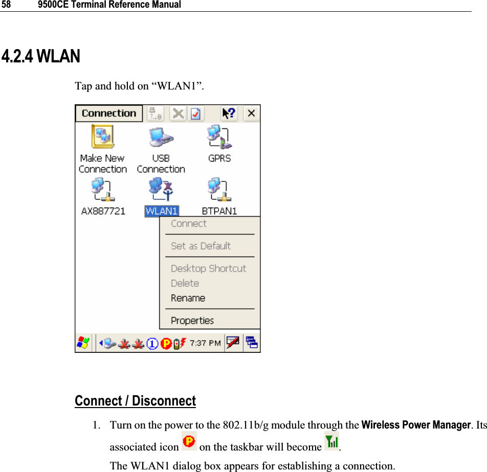
![Chapter 4 61 Icons Description By default, the 802.11b/g module is disabled. No status icon. Enable the 802.11b/g module through the Wireless Power Manager. The icon on the taskbar will become , and the status icon will appear.When successfully connecting to an access point or other Wi-Fi enabled device, the status icon will become .PropertiesBy default, DHCP is enabled, and therefore, there is no need to configure the IP settings. If you want to assign a static IP address to the terminal, tap and hold on “WLAN1”, and then select [Properties]. Note: Only change these settings according to your network administrator’s instructions.](https://usermanual.wiki/CipherLab/9500CE1/User-Guide-921373-Page-69.png)
![62 9500CE Terminal Reference Manual 4.2.5 BTPAN Tap and hold on “BTPAN1”. Enable / DisableIcons Description By default, the Ethernet module is enabled. When the Bluetooth PAN service is connected through the Bluetooth Manager, the status icon will become .Tap and hold on “BTPAN1”, and select [Disable]. The status icon will disappear. PropertiesBy default, DHCP is enabled, and therefore, there is no need to configure the IP settings. If you want to assign a static IP address to the terminal, tap and hold on “BTPAN1”, and then select [Properties]. Note: Only change these settings according to your network administrator’s instructions.](https://usermanual.wiki/CipherLab/9500CE1/User-Guide-921373-Page-70.png)
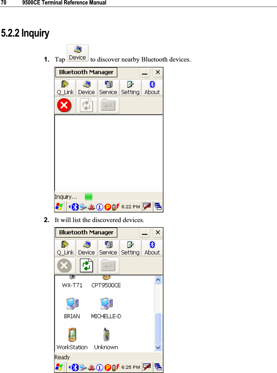
![66 9500CE Terminal Reference Manual Note: To start Bluetooth PAN service, go to Start > Settings > Network and Dial-up Connections.ToolbarButtons Description See Also Tap this button to view shortcuts to preferred Bluetooth services, which may be provided on different Bluetooth devices. Then tap a desired Bluetooth service to establish a quick link. You will have to make a connection and created a shortcut to a specific Bluetooth service first. Tap this button to view the Bluetooth devices discovered during this session.If you tap the button for the first time, it will start the inquiry process to discover nearby Bluetooth devices. Tap this button to view the Bluetooth services provided. By default, these services are all available, and therefore, displayed along with a plug icon “ ”. To view properties of a service, tap and hold it. Then select [Properties]. To disable a service, tap and hold it. Then select [Stop]. Serial Port PropertiesIf “Auto Server COM Port” is enabled – If “Auto Server COM Port” is disabled, you can select a COM port by following these steps:](https://usermanual.wiki/CipherLab/9500CE1/User-Guide-921373-Page-74.png)
![Chapter 5 ʳʳʳʳʳʳʳʳʳʳʳʳʳʳʳʳʳʳʳʳʳʳʳʳʳʳʳʳʳʳʳʳʳʳʳ 69 remote Serial Port service will be assigned automatically. When disabled, you can select a COM port by selecting [Connect]: Auto Server COM Port: When enabled, the default COM port for local Serial Port service will be assigned automatically. Tap this button to minimize the Bluetooth Manager window. Tap this button to exit the Bluetooth Manager. Tap this button to stop inquiring. Tap this button to refresh the deice list. When using the File Transfer service on a remote device, you can tap this button to move up one level if a subfolder exists. Tap this button to view the Bluetooth profiles supported: SPP for Serial Port Profile OPP for Object Push Profile FTP for File Transfer Profile DUN for Dial-Up Networking Profile (supports Client only) Note that the terminal also supports the following profiles: PAN Service Profile Human Interface Device (HID) Profile](https://usermanual.wiki/CipherLab/9500CE1/User-Guide-921373-Page-77.png)
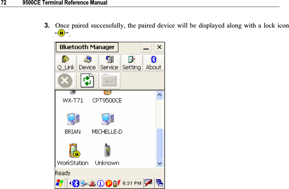
![Chapter 5 71 5.2.3 Pair When authentication is enabled on the target device, you will have to pair with it before starting a connection. 1. From the device list, tap and hold on the desired device and tap [Pair]. 2. Enter the PIN code that is specified on the remote device.](https://usermanual.wiki/CipherLab/9500CE1/User-Guide-921373-Page-79.png)
![Chapter 5 73 5.2.4 Connect 1. From the device list above, double-tap a device to find out the available Bluetooth services. 2. Tap and hold a desired Bluetooth service, e.g. Serial Port Service, to establish a connection. The connected service will be displayed along with a plug icon “ ”.Tap [Connect] and then select a COM port when “Auto Client COM Port” is disabled in .](https://usermanual.wiki/CipherLab/9500CE1/User-Guide-921373-Page-81.png)
![74 9500CE Terminal Reference Manual 3. If you wish to add a service to the Q_Link list for establishing a quick connection in the future, tap and hold it, and then select [Create Shortcut]. Steps to access the Object Push service:1. Tap and hold the Object Push service. 2. Select [Push file] to send a file or PIM item, e.g. a business card. 3. Choose the file you wish to send.](https://usermanual.wiki/CipherLab/9500CE1/User-Guide-921373-Page-82.png)
![Chapter 5 75 4. The terminal will start transferring the file. Steps to access the File Transfer service:1. Tap and hold the File Transfer service. 2. Select [Connect] (and assign COM port if necessary). 3. Tap and hold on anywhere blank. Then, select [Add file].](https://usermanual.wiki/CipherLab/9500CE1/User-Guide-921373-Page-83.png)
![76 9500CE Terminal Reference Manual 4. Choose the file you wish to upload to the remote device. 5. The terminal will start transferring the file. 6. To download a file from the remote device, tap and hold on a desired file. Then, select [Get file].](https://usermanual.wiki/CipherLab/9500CE1/User-Guide-921373-Page-84.png)
![Chapter 5 77 5.2.5 Stop Bluetooth Services Tap on the toolbar of the Bluetooth window to stop all Bluetooth connections. When the Bluetooth window is minimized, tap and hold on the taskbar, and then select [Exit]. Note: You may need to stop using the Bluetooth services, in order to conserve battery power, or in situations where the use of radio is prohibited, such as on airplanes, in hospitals, etc. To stop Bluetooth PAN service, go to Start > Settings > Network and Dial-up Connections.](https://usermanual.wiki/CipherLab/9500CE1/User-Guide-921373-Page-85.png)
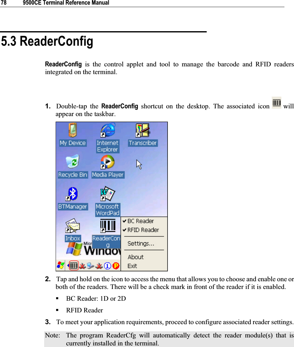
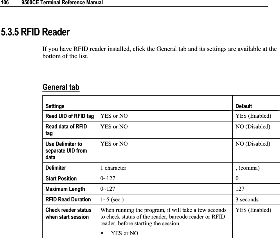
![Chapter 5 79 5.3.1 Configure Reader Settings Tap and hold on , and then select BC Reader or RFID Reader. If it is ticked, the reader is enabled. Otherwise, it is disabled. The default reader is BC Reader for reading barcodes. If the RFID Reader is installed, the option will be available. If you need to change the factory settings, select [Settings]. The reader configurations depend on the barcode reader installed. To identify the barcode reader, check inside the “Active Device” setting. Active Device Description 1D Reader The scan engine is CCD or Laser. 1D Long Range Laser The scan engine is Long Range Laser or Extra Long Range Laser. 2D Reader The scan engine can read linear and 2D barcodes. RFID The reader can read RFID tags. Note: (1) For barcode settings, click the 1D or 2D tab that is next to the General tab. (2) For RFID settings, click the General tab and roll to the bottom of the list. (3) If you wish to reload the default settings, delete the ReaderCfg.ini file in DiskOnChip.](https://usermanual.wiki/CipherLab/9500CE1/User-Guide-921373-Page-87.png)
![Chapter 5 ʳʳʳʳʳʳʳʳʳʳʳʳʳʳʳʳʳʳʳʳʳʳʳʳʳʳʳʳʳʳʳʳʳʳʳʳʳʳ 81 Note: For the use of a different program rather than ReaderCfg, a dynamic-link library (DLL) file is provided. Auto ENTER This function can spare you the trouble of pressing the [Enter] key on the terminal to confirm each scan. It will automatically add an ENTER character in front or to the end of one scan. No Scan + ENTER (time-saving) ENTER + Scan (efficient for continuous scanning) Scan + ENTER Auto ENTER Character *Auto ENTER must be enabled. None Carriage Return Tab SpaceComma Semicolon Carriage Return Prefix Code 0~10 characters NULL Suffix Code 0~10 characters NULL Include Cody Type YES or NO NO (Disabled) Include Cody Length YES or NO NO (Disabled) Scan Mode Refer to Appendix I Comparison of Scan Modes.Auto Off Continuous Auto Power Off Alternate Momentary Repeat LaserTestAiming Laser mode Barcode Decode Timeout 1~255 (sec.) 3 seconds Barcode Read Redundancy Select a desired level of reading (decoding) security. Comprise some speed for getting more security when necessary. For example, if “None” is selected, it only requires one successful decoding to make the reading valid. If “Three times” is selected, it needs to successfully decode three more times to make the reading valid. None None](https://usermanual.wiki/CipherLab/9500CE1/User-Guide-921373-Page-89.png)
![Chapter 5 87 and 979 will be converted to ISBN. Convert to ISSN When enabled, the EAN-13 reading that starts with 977 will be converted to ISSN. OFF (Disabled) Transmit Checksum The checksum character is included in the data being transmitted. ON (Enabled) Transmit Addon 2 When enabled, EAN-13 Addon 2 can be decoded too. OFF (Disabled) Transmit Addon 5 When enabled, EAN-13 Addon 5 can be decoded too. OFF (Disabled) UPC-A Supported on CCD / Laser Default *Share the setting of EAN-13. Enabled Convert to EAN-13 The UPC-A reading will be expanded into EAN-13. It will then be processed according to the settings of EAN-13. ON (Enabled) Transmit System Number The system number is included in the data being transmitted. ON (Enabled) Transmit Checksum The checksum character is included in the data being transmitted. ON (Enabled) Transmit Addon 2 Share the setting of EAN-13 OFF (Disabled) Transmit Addon 5 Share the setting of EAN-13 OFF (Disabled) Telepen Supported on CCD / Laser Default Enabled or Disabled Disabled Telepen Type Telepen Numeric is supported by default. Select AIM (Full ASCII) so that Telepen Full ASCII is supported. All the alphanumeric and special characters are included. Original (Numeric) RSS-14 Supported on CCD / Laser Default Enabled or Disabled Disabled Transmit Checksum The checksum character is included in the data being transmitted. ON (Enabled) Transmit Application IDThe Application ID is included in the data being transmitted. ON (Enabled) Transmit Code ID The Code ID (default to “]e0”) is included in the data being transmitted. ON (Enabled)](https://usermanual.wiki/CipherLab/9500CE1/User-Guide-921373-Page-95.png)
![88 9500CE Terminal Reference Manual RSS Limited Supported on CCD / Laser Default Enabled or Disabled Disabled Transmit Checksum The checksum character is included in the data being transmitted. ON (Enabled) Transmit Application IDThe Application ID is included in the data being transmitted. ON (Enabled) Transmit Code ID The Code ID (default to “]e0”) is included in the data being transmitted. ON (Enabled) RSS Expanded Supported on CCD / Laser Default Enabled or Disabled Disabled Transmit Code ID The Code ID (default to “]e0”) is included in the data being transmitted. ON (Enabled) Code 93 Supported on CCD / Laser Default Enabled or Disabled Enabled Code 128 Supported on CCD / Laser Default Enabled or Disabled Enabled EAN-128 Supported on CCD / Laser Default Share the setting of Code 128 Enabled Transmit Code ID When enabled, the Code ID (default to “]C1”) is included in the data being transmitted. OFF (Disabled)](https://usermanual.wiki/CipherLab/9500CE1/User-Guide-921373-Page-96.png)
![90 9500CE Terminal Reference Manual Note: For the use of a different program rather than ReaderCfg, a dynamic-link library (DLL) file is provided. Auto ENTER This function can spare you the trouble of pressing the [Enter] key on the terminal to confirm each scan. It will automatically add an ENTER character in front or to the end of one scan. No Scan + ENTER (time-saving) ENTER + Scan (efficient for continuous scanning) Scan + ENTER Auto ENTER Character *Auto ENTER must be enabled. None Carriage Return Tab SpaceComma Semicolon Carriage Return Prefix Code 0~10 characters NULL Suffix Code 0~10 characters NULL Include Cody Type YES or NO NO (Disabled) Include Cody Length YES or NO NO (Disabled) Barcode Decode Timeout 1~99 (0.1 sec.) 3.0 seconds Timeout When Decode Same Barcode0~99 (0.1 sec.) 1.0 seconds AIM Duration 0~99 (0.1 sec.) 0.0 seconds RFID Settings will be displayed if the RFID reader is installed!Check reader status when start session When running the program, it will take a few seconds to check status of the reader, barcode reader or RFID reader, before starting the session. YES or NO YES (Enabled)](https://usermanual.wiki/CipherLab/9500CE1/User-Guide-921373-Page-98.png)
![Chapter 5 97 Note: For the use of a different program rather than ReaderCfg, a dynamic-link library (DLL) file is provided. Auto ENTER This function can spare you the trouble of pressing the [Enter] key on the terminal to confirm each scan. It will automatically add an ENTER character in front or to the end of one scan. No Scan + ENTER (time-saving) ENTER + Scan (efficient for continuous scanning) Scan + ENTER Auto ENTER Character*Auto ENTER must be enabled. None Carriage Return Tab SpaceComma Semicolon Carriage Return Prefix Code 0~10 characters NULL Suffix Code 0~10 characters NULL Include Cody Type YES or NO NO (Disabled) Include Cody Length YES or NO NO (Disabled) Barcode Decode Timeout 5~99 (0.1 sec.) 9.9 seconds Timeout When Decode Same Barcode0~99 (0.1 sec.) 0.6 seconds Decoding Autoexposure ON or OFF ON Decoding Illumination ON or OFF ON Decoding Aiming Pattern ON or OFF ON RFID Settings will be displayed if the RFID reader is installed!Check reader status when start session When running the program, it will take a few seconds to check status of the reader, barcode reader or RFID reader, before starting the session. YES or NO YES (Enabled)](https://usermanual.wiki/CipherLab/9500CE1/User-Guide-921373-Page-105.png)
![104 9500CE Terminal Reference Manual TLC-39 Enable UPC Composite Mode UPC barcodes can be “linked” with a 2D barcode during transmission as if they were one barcode. There are three options for these composite barcodes: UPC Never Linked (to transmit UPC barcodes only, regardless of whether a 2D barcode is detected) UPC Always Linked (to transmit UPC barcodes and the 2D portion; if 2D is not present, it will not transmit UPC barcodes, i.e. CC-A/B or CC-C must be enabled!) Autodiscriminate UPC Composites (to transmit UPC barcodes, as well as the 2D portion if present) UPC Always Linked Enable UCC/EAN Code 128 Emulation YES or NO NO (Disabled) 2D Symbologies Supported on 2D Reader Default Enable PDF417 YES or NO YES (Enabled) Enable MicroPDF417 YES or NO NO (Disabled) Enable Code 128 Emulation YES or NO *MicroPDF417 must be enabled! If Code 128 Emulation is enabled, these MicroPDF417 barcodes are transmitted with one of the following prefixes: ]C1 if the first codeword is 903-907, 912, 914, 915 ]C2 if the first codeword is 908 or 909 ]C0 if the first codeword is 910 or 911 If disabled, they are transmitted with one of the following prefixes: ]L3 if the first codeword is 903-907, 912, 914, 915 ]L4 if the first codeword is 908 or 909 ]L5 if the first codeword is 910 or 911 NO (Disabled) Enable Data Matrix YES or NO YES (Enabled) Enable MaxiCode YES or NO YES (Enabled) Enable QR Code YES or NO YES (Enabled) Macro PDF Supported on 2D Reader Default Transmit / Decode ModeThere are three options for handling Macro PDF decoding: Passthrough All Symbols](https://usermanual.wiki/CipherLab/9500CE1/User-Guide-921373-Page-112.png)
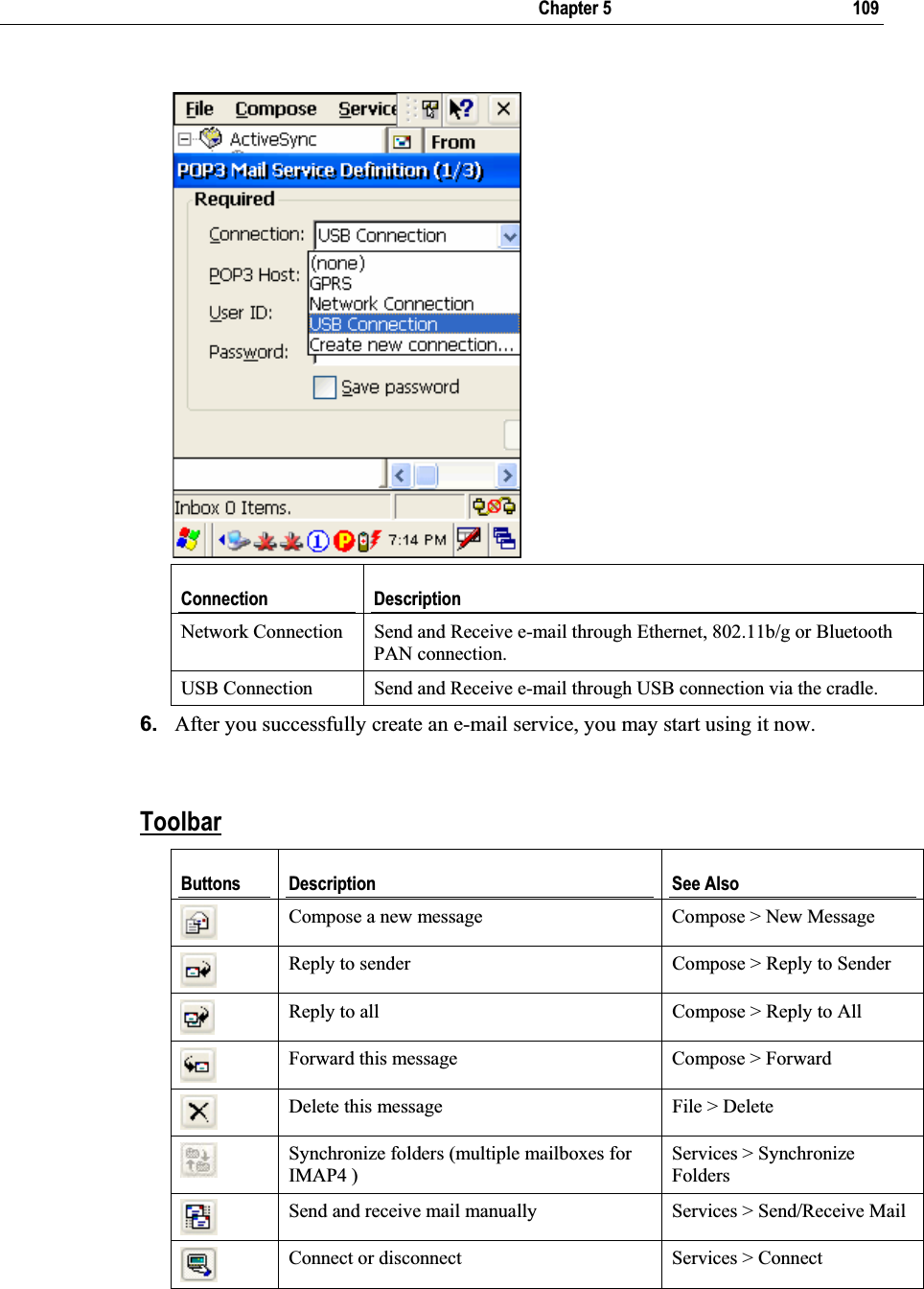
![108 9500CE Terminal Reference Manual 3. Tap and drag the dialog box to show the right edge. Tap [Add] to create an e-mail service. 4. In the Service Name dialog box, select POP3 Mail or IMAP4 Mail for the service type. Change the name of e-mail service if necessary. Tap [OK]. 5. Proceed with the POP3 or IMAP4 Mail Service Definition (from 1/3 to 3/3).](https://usermanual.wiki/CipherLab/9500CE1/User-Guide-921373-Page-116.png)
![110 9500CE Terminal Reference Manual When connected, it will send and receive mail automatically. 5.4.2 Synchronize Inbox When you seat the terminal in the cradle and connect it to your computer for the first time, ActiveSync 3.7.1 will guide you through setting up a partnership between the terminal and your computer. Refer to ActiveSync with a Computer.Select the check box of Inbox as shown below, and click [Settings] to configure it. Note: ActiveSync 4.x does not support Inbox Synchronization. We recommend that you have ActiveSync 3.7.1 installed on your computer.](https://usermanual.wiki/CipherLab/9500CE1/User-Guide-921373-Page-118.png)