CipherLab 9500CE1 Terminal User Manual
CipherLab Co., Ltd. Terminal
User manual

Printed on 19 March, 2008
Reference Manual
9500CE Terminal
Terminal
Version 1.03
II
Copyright © 2006 CIPHERLAB CO., LTD.
All rights reserved
The software contains proprietary information of CIPHERLAB CO., LTD.; it is provided under a license
agreement containing restrictions on use and disclosure and is also protected by copyright law. Reverse
engineering of the software is prohibited.
Due to continued product development this information may change without notice. The information and
intellectual property contained herein is confidential between CIPHERLAB and the client and remains the
exclusive property of CIPHERLAB CO., LTD. If you find any problems in the documentation, please
report them to us in writing. CIPHERLAB does not warrant that this document is error-free.
No part of this publication may be reproduced, stored in a retrieval system, or transmitted in any form or by
any means, electronic, mechanical, photocopying, recording or otherwise without the prior written
permission of CIPHERLAB CO., LTD.
For product consultancy and technical support, please contact your local sales representative. Also, you may
visit our web site for more information.
The CipherLab logo is a registered trademark of CIPHERLAB CO., LTD.
Microsoft, Windows, and the Windows logo are registered trademarks of Microsoft Corporation in the
United States and/or other countries.
Bluetooth is a trademark of Bluetooth SIG, Inc., U.S.A.
Other product names mentioned in this manual may be trademarks or registered trademarks of their
respective companies and are hereby acknowledged.
The editorial use of these names is for identification as well as to the benefit of the owners, with no intention
of infringement.
CIPHERLAB CO., LTD.
Website: http://www.cipherlab.com
Copyright Notice

III
This equipment has been tested and found to comply with the limits for a Class B digital device, pursuant to
Part 15 of the FCC Rules. These limits are designed to provide reasonable protection against harmful
interference in a residential installation. This equipment generates, uses and can radiate radio frequency
energy and, if not installed and used in accordance with the instructions, may cause harmful interference to
radio communications. However, there is no guarantee that interference will not occur in a particular
installation. If this equipment does cause harmful interference to radio or television reception, which can be
determined by turning the equipment off and on, the user is encouraged to try to correct the interference by
one or more of the following measures:
Reorient or relocate the receiving antenna.
Increase the separation between the equipment and receiver.
Connect the equipment into an outlet on a circuit different from that to which the receiver is connected.
Consult the dealer or an experienced radio/TV technician for help.
RISK OF EXPLOSION IF BATTERY IS REPLACED BY AN INCORRECT TYPE
DISPOSE OF USED BATTERIES ACCORDING TO THE INSTRUCTIONS
The use of any batteries or charging devices, which are not originally sold or manufactured by
CipherLab, will void your warranty and may cause damage to human body or the product itself.
The charging and communication cradle uses an AC power adaptor. A socket outlet shall be installed
near the equipment and shall be easily accessible. The power adaptor should comply with L.P.S test.
Make sure there is stable power supply for the terminal or its peripherals to operate properly.
DO NOT disassemble, incinerate or short circuit the battery pack.
DO NOT expose the terminal or the battery pack to any flammable sources.
Under no circumstances, internal components are self-serviceable.
Per FDA and IEC standards, the scan engines described in this manual are not given a laser
classification. However, the following precautions should be observed:
CAUTION
This laser component emits FDA/IEC Class 2 laser light at the exit port. Do not stare into beam.
FCC Regulations
Important Safety Precautions
This equipment complies with FCC radiation exposure limits set forth for an uncontrolled environment.
This equipment should be installed and operated with minimum distance 20cm between the radiator &your body.
It only operated in hand-held used. If you only transfer data to Host by WLAN, please keep the minimum
distance 20cm between machine & your body.
This device complies with part 15 of the FCC Rules. Operation is subject to the following two conditions:
(1) This device may not cause harmful interference, and (2) this device must accept any
interference received, including interference that may cause undesired operation.
This transmitter must not be co-located or operating in conjunction with anyother antenna or transmitter.

IV
This terminal is intended for industrial use. The terminal is rated IP 64, however, it may do damage to
the terminal when being exposed to extreme temperatures or soaked wet.
When the body of the terminal gets dirty, use a clean and wet cloth to wipe off the dust. DO NOT
use/mix any bleach or cleaner. Always keep the LCD dry.
For a liquid crystal display (LCD) or touch screen, use a clean, non-abrasive, lint-free cloth to wipe dust
off the screen. DO NOT use any pointed or sharp object to move against the surface.
Battery disposal – For green-environment issue, it is important that batteries should be recycled in a
proper way.
If you want to put away the terminal for a period of time, download the collected data to a host computer,
and then take out the battery pack. Store the terminal and battery pack separately.
When the terminal resumes its work, the main and backup batteries will take a certain time to become
fully charged.
If you shall find the terminal malfunctioning, write down the specific scenario and consult your local
sales representative.
Care & Maintenance
Industry Canada - Class B
This digital apparatus does not exceed the Class B limits for radio noise emissions from digital apparatus as
set out in the interference-causing equipment standard entitled "Digital Apparatus," ICES-003 of Industry
Canada.
Cet appareil numerique respecte les limites de bruits radioelectriques applicables aux appareils numeriques de
Classe B prescrites dans la norme sur le material brouilleur: "Appareils Numeriques," NMB-003 edictee par
l'Industrie.
(1) this device may not cause interference,and (2) this device must accept any interference, including
interference that may cause undesired operation of the device."

V
For any portable device, power management is a critical issue especially when you are on the road. Below
are some tips to help you save battery power.
To speed up charging the terminal, turn off the terminal and seat it in the cradle.
Bring a second battery pack on the road.
Stop wireless connectivity, Bluetooth, 802.11b/g that is not in use.
The power to the wireless modules, 802.11b/g, is controlled by PwrMg.exe (the Wireless Power
Manager), which can be found on the taskbar ( ).
To save power, go to Start > Settings > Control Panel for related settings:
Double-tap the Display icon
1. Tap the Backlight tab.
2. Select one or both of the check boxes to automatically turn off the LCD backlight when using batteries
or external power. From the appropriate list, select the amount of time the device should be idle before
the backlight is turned off.
3. Then, tap the [Advanced] button to view more backlight options.
4. In the Settings tab, you can dim the LCD backlight when in a well-lit working area for AC and battery
powered respectively.
Double-tap the Power icon
1. Tap the Schemes tab.
2. Select the desired power scheme and options for suspending operation when not in use.
Power Management

i
Contents
Copyright Notice II
FCC Regulations III
Important Safety Precautions III
Care & Maintenance IV
Power Management V
Preface 1
Revision History .......................................................................................................
ᙑᎄ
!
ࡸآࡳᆠ᧘Ζ
CHAPTER 1 - Introduction 3
1.1 Unpacking the package...........................................................................................................................3
1.2 Options....................................................................................................................................................3
1.3 Product Highlights ..................................................................................................................................4
1.4 Nomenclature..........................................................................................................................................5
1.4.1 9500CE Terminal .....................................................................................................................5
1.4.2 Accessories & Peripherals ........................................................................................................6
1.4.3 Dimensions ...............................................................................................................................7
1.5 Features...................................................................................................................................................8
1.5.1 Battery ......................................................................................................................................8
1.5.2 CPU ........................................................................................................................................11
1.5.3 Memory & Calendar...............................................................................................................11
1.5.4 Keypad....................................................................................................................................13
1.5.5 LCD........................................................................................................................................16
1.5.6 Status LED..............................................................................................................................19
1.5.7 Speaker ...................................................................................................................................19
1.5.8 Vibrator ..................................................................................................................................19
1.5.9 Reader.....................................................................................................................................20
1.5.10 Wireless Support...................................................................................................................22
1.5.11 Resistance.............................................................................................................................22

ii Contents
CHAPTER 2 - Installation 23
2.1 Main & Backup Batteries .....................................................................................................................24
2.2 Hand Strap ............................................................................................................................................26
2.3 Pistol Grip.............................................................................................................................................27
2.4 Cradle....................................................................................................................................................28
2.4.1 Status Indicators .....................................................................................................................28
2.4.2 Communication Ports .............................................................................................................29
CHAPTER 3 - Windows CE Basics 31
3.1 General..................................................................................................................................................32
3.1.1 Device Configuration .............................................................................................................33
3.1.2 Turn On/Off............................................................................................................................34
3.1.3 Desktop Window ....................................................................................................................34
3.1.4 Input Methods.........................................................................................................................38
3.2 System Reset.........................................................................................................................................39
3.2.1 Soft Reset................................................................................................................................39
3.2.2 Hard Reset ..............................................................................................................................39
3.3 Firmware Update ..................................................................................................................................40
3.4 ActiveSync with a Computer................................................................................................................41
3.5 Quick Launch a Program ......................................................................................................................42
3.5.1 Add a Program........................................................................................................................42
3.5.2 Add a Subfolder......................................................................................................................45
3.5.3 Exit a Program........................................................................................................................46
3.5.4 Switch between Programs.......................................................................................................46
3.6 Install a New Program ..........................................................................................................................47
3.6.1 Add/Remove Programs...........................................................................................................47
3.6.2 Copy & Paste..........................................................................................................................47
3.7 Uninstall a Program ..............................................................................................................................48
3.7.1 ActiveSync: Add/Remove Programs......................................................................................48
3.7.2 Control Panel > Remove Programs ........................................................................................48
3.8 Backup & Restore Programs.................................................................................................................50
CHAPTER 4 - Configuration 51
4.1 General Settings....................................................................................................................................51
4.2 Connections ..........................................................................................................................................54
4.2.1 USB Connection.....................................................................................................................56
4.2.2 AX88772 (Ethernet) ...............................................................................................................57
4.2.3 WLAN....................................................................................................................................58
4.2.4 BTPAN...................................................................................................................................62
CHAPTER 5 - Applications 63
5.1 Wireless Power Manager ......................................................................................................................64
5.2 Bluetooth Manager ...............................................................................................................................65
5.2.1 Start Bluetooth Services .........................................................................................................65
5.2.2 Inquiry ....................................................................................................................................70
5.2.3 Pair..........................................................................................................................................71
5.2.4 Connect...................................................................................................................................73
5.2.5 Stop Bluetooth Services..........................................................................................................77

Contents iii
5.3 ReaderConfig........................................................................................................................................78
5.3.1 Configure Reader Settings......................................................................................................79
5.3.2 1D Reader - CCD / Laser........................................................................................................80
5.3.3 1D Reader - (Extra) Long Range Laser ..................................................................................89
5.3.4 2D Reader...............................................................................................................................96
5.3.5 RFID Reader.........................................................................................................................106
5.4 Inbox...................................................................................................................................................107
5.4.1 Create an E-mail Box ...........................................................................................................107
5.4.2 Synchronize Inbox................................................................................................................110
Specifications 111
APPENDIX I - Comparison of Scan Modes 113

iv Contents
Table of Figures
Figure 1: Nomenclature (front & back) .....................................................................................5
Figure 2: Nomenclature of accessories.......................................................................................6
Figure 3: Dimensions ...................................................................................................................7
Figure 4: 27-key layout ..............................................................................................................13
Figure 5: DIP switch for backup battery pack ........................................................................24
Figure 6: Installing battery pack ..............................................................................................25
Figure 7: Installing hand strap .................................................................................................26
Figure 8: Installing pistol grip ..................................................................................................27
Figure 9: Cradle LEDs ..............................................................................................................28

1
Delivered in the same form factor of the 9500PPC Series running Windows Mobile 2003SE,
the 9500CE Terminal Series is the newest member to the Mobile Computer family. As
suggested by its model designation, it is designed to run Windows CE 5.0, and therefore,
allows more flexibility in customization of applications.
CipherLab has integrated powerful utilities for data collection, processing, and transmission.
Its large color transflective TFT display guarantees ease in reading in all lighting conditions.
Built-in with Bluetooth and 802.11b/g technologies, delivers a total wireless solution.
The 9500CE Terminal Series is robust in construction to meet industry grade requirements,
and has been found durable and resistant to shock, water, and dust. It is specifically
designed for all-day, everyday use as well as for data-intensive applications in harsh
environments.
This manual serves to guide you through how to install, configure, and operate the terminal.
The Care & Maintenance section is specifically prepared for those who are in charge of
taking care of the terminal.
We recommend you to keep one copy of the manual at hand for quick reference or
maintenance purposes. To avoid any improper disposal or operation, please read the manual
thoroughly before use.
Thank you for choosing CipherLab products!
Preface

3
This chapter explains the hardware parts and features of the 9500CE Terminal terminal.
1.1 Unpacking the package
The following items are included in the package. Save the box and packaging material for
future use in case you need to store or ship the terminal.
9500CE Terminal
Rechargeable Li-ion battery pack
Stylus
Hand strap
Software CD (this Reference Manual is included)
Note: For battery charging, you will need to purchase a charging cradle separately.
1.2 Options
There are a number of optional accessories to enhance the total performance of the terminal.
Refer to related sections for details on installation.
Accessories Features...
Reader One scan engine:
1D - CCD, Laser, Long Range Laser, Extra Long Range Laser
And/or the RFID reader
Rechargeable Battery Pack Rechargeable Li battery for non-stop operation
Pistol Grip, Detachable Facilitating scanning with one hand
Charging & Communication
Cradle
Charging of the terminal and one spare battery at the same time
while transmitting/receiving data.
CHAPTER 1
Introduction

4 9500CE Terminal Reference Manual
1.3 Product Highlights
Microsoft Windows CE 5.0 software for operating system
520 MHz Intel PXA270 processor
A color transflective TFT display delivers excellent visibility in all lighting conditions
128 MB non-volatile NAND flash memory to store OS and software programs
(part of the free space is used as a storage card called DiskOnChip)
128 MB SDRAM to store and run programs, as well as store program data
Ergonomic design, ruggedized yet streamlined, with hand strap for secure hold
Built tough to survive harsh environments - splash, dust & drop resistant
Dual mode support - One scan engine (integrated barcode scanner/imager) plus one
RFID reader
Wireless connectivity includes Bluetooth and 802.11b/g
Programmable feedback includes speaker and vibrator
Accessories and peripherals include pistol grip, international AC charging cradle, etc.
Chapter 1 5
1.4 Nomenclature
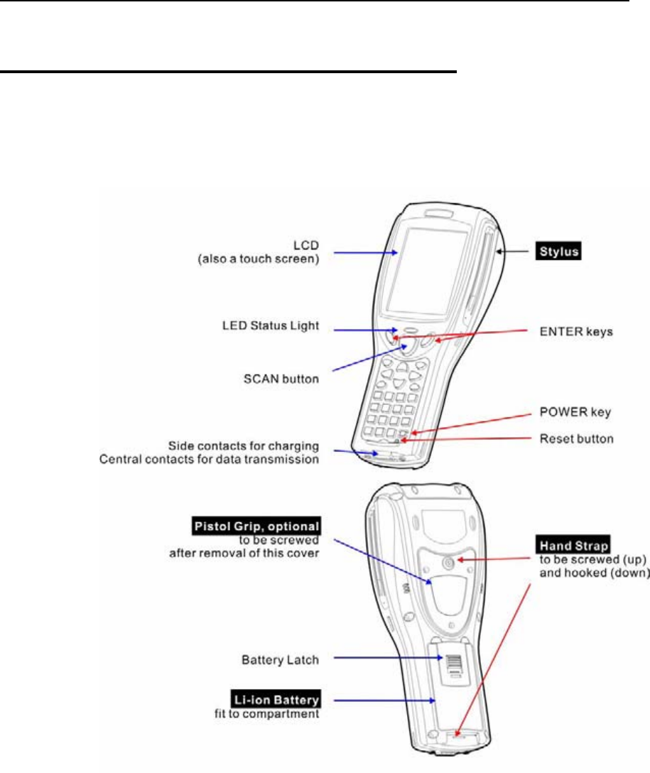
1.4.1 9500CE Terminal
Figure 1: Nomenclature (front & back)
6 9500CE Terminal Reference Manual
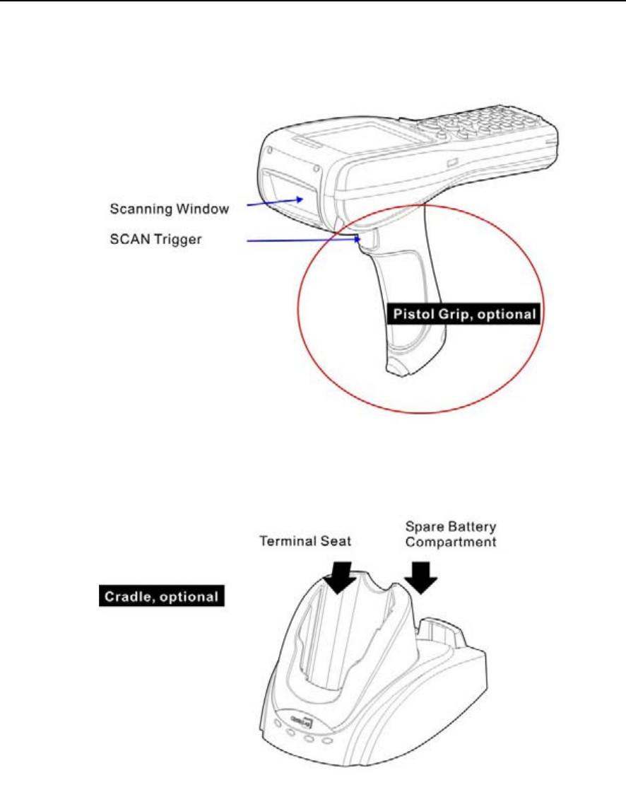
1.4.2 Accessories & Peripherals
Figure 2: Nomenclature of accessories
Chapter 1 7
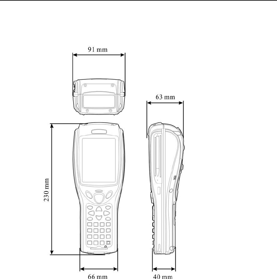
1.4.3 Dimensions
Figure 3: Dimensions

8 9500CE Terminal Reference Manual
1.5 Features
1.5.1 Battery
Main Battery
This rechargeable 3.7 V/4000 mAh Li-ion battery pack serves as the main power.
Normally, it takes approximately four hours to fully charge the battery. The
charging time may vary by working condition.
During normal operation, the terminal can work for up to 16 hours.
Warning: Using backlight, wireless connectivity, and peripherals while on battery
power will substantially reduce battery life.
Backup Battery
The backup battery takes charge when the main battery is removed or drained out.
If fully charged, it will help retain data in SDRAM and maintain the system running
in suspend mode for at least 30 minutes without the main battery. In the meantime,
you have to replace the main battery as soon as possible.
Battery Charge
Initial Charging
The main and backup batteries may not be charged to full for shipment. When you
first receive the package, you will need to charge batteries to full before using the
terminal.
Note: To charge the batteries for the first time, it requires approximately 8 hours.
After the initial charging, it takes only 4 hours to charge the batteries to full.
Because the internal backup battery is constantly charged from the main battery, the
initial charging requires installing the battery pack to the terminal and then seating
the terminal in the cradle for charging. This will have both the main and backup
batteries charged at the same time.
Note: To charge the backup battery, make sure that you slide the DIP switch inside the
battery compartment to the ON position.
Chapter 1 9
Caution of Low Battery Charge
The battery pack is the only power source for the terminal to work. It also charges
the backup battery so that the data stored in SDRAM can be retained properly.
Therefore, when the main battery charge goes low, replace the battery pack with a
charged one or seat it in the cradle for charging as soon as possible. Always save
data before it is too late.
Warning: Data loss may occur with SDRAM during low battery condition. Always
save data before running out of power or keep a fresh battery for
replacement.
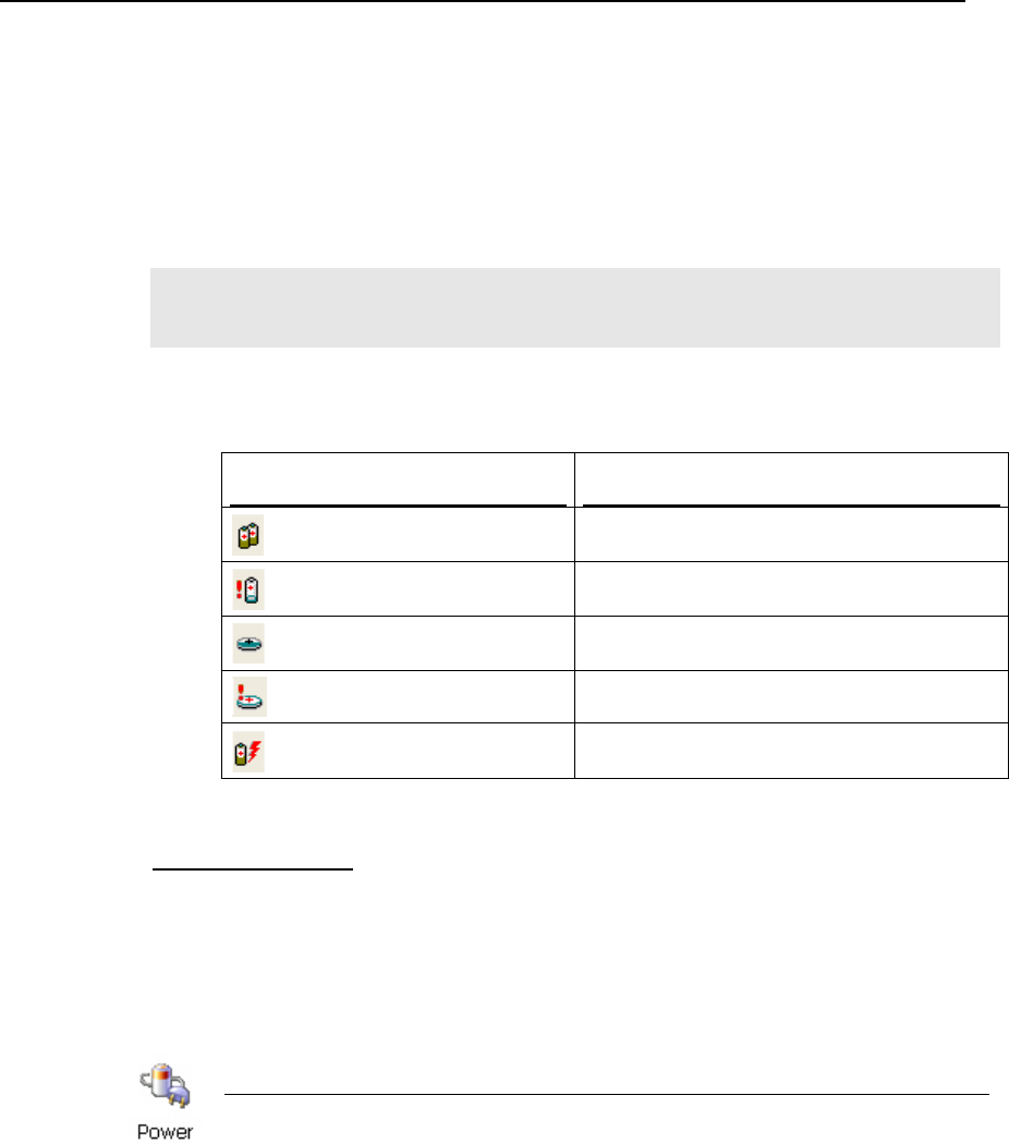
Battery Status Icons
Status Icons Description
Main battery is low.
Main battery is very low.
Backup battery is low.
Backup battery is very low.
Main battery is charging.
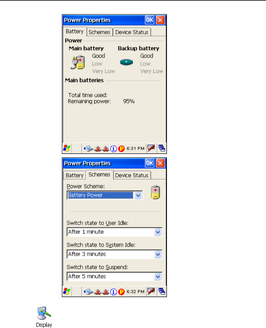
Power Properties
The system can be set to three different states to conserve power:
User Idle state
System Idle state
Suspend state
Start > Settings > Control Panel and double-tap the Power icon
1. In the Battery tab, you can always monitor the charging status.
2. Tap the Schemes tab.
3. Select the desired power scheme and options for suspending operation when not
in use. The time choices represent the amount of time that must pass before the
system will switch to the next power conservation state.
10 9500CE Terminal Reference Manual
To conserve more power, you may go to Start > Settings > Control Panel and
double-tap the Display icon to configure the backlight setting.

Chapter 1 11
1.5.2 CPU
Built to run Windows CE 5.0, the 9500CE Terminal terminal is equipped with an Intel
X-Scale 520 MHz RISC microprocessor.
1.5.3 Memory & Calendar
Read-only Memory (ROM)
A total of 128 megabytes flash memory.
Mostly, it is for storing OS (Windows CE 5.0) and custom application programs.
Yet a small portion of the memory is referred to as DiskOnChip, which can store data and
programs that you wish to retain even after a hard reset.
Random-access Memory (RAM)
A total of 128 megabytes SDRAM.
It is used for storing and running programs, as well as storing program data.
Its contents will be retained by the backup battery.
Calendar
Equipped with a calendar chip for accurate time/date logging.
Non-stop operation is provided through the backup battery.
Caution of Data Loss
When the main battery is removed or drained out, the backup battery is to retain the
contents of SDRAM and maintain the OS in suspend mode for at least 30 minutes,
on condition that the backup battery has already been fully charged.
If the terminal is to be put away for a couple of days, you should be aware that data
loss occurs when both the main and backup batteries discharge completely. It is
necessary to backup data and files before putting away the terminal.
12 9500CE Terminal Reference Manual
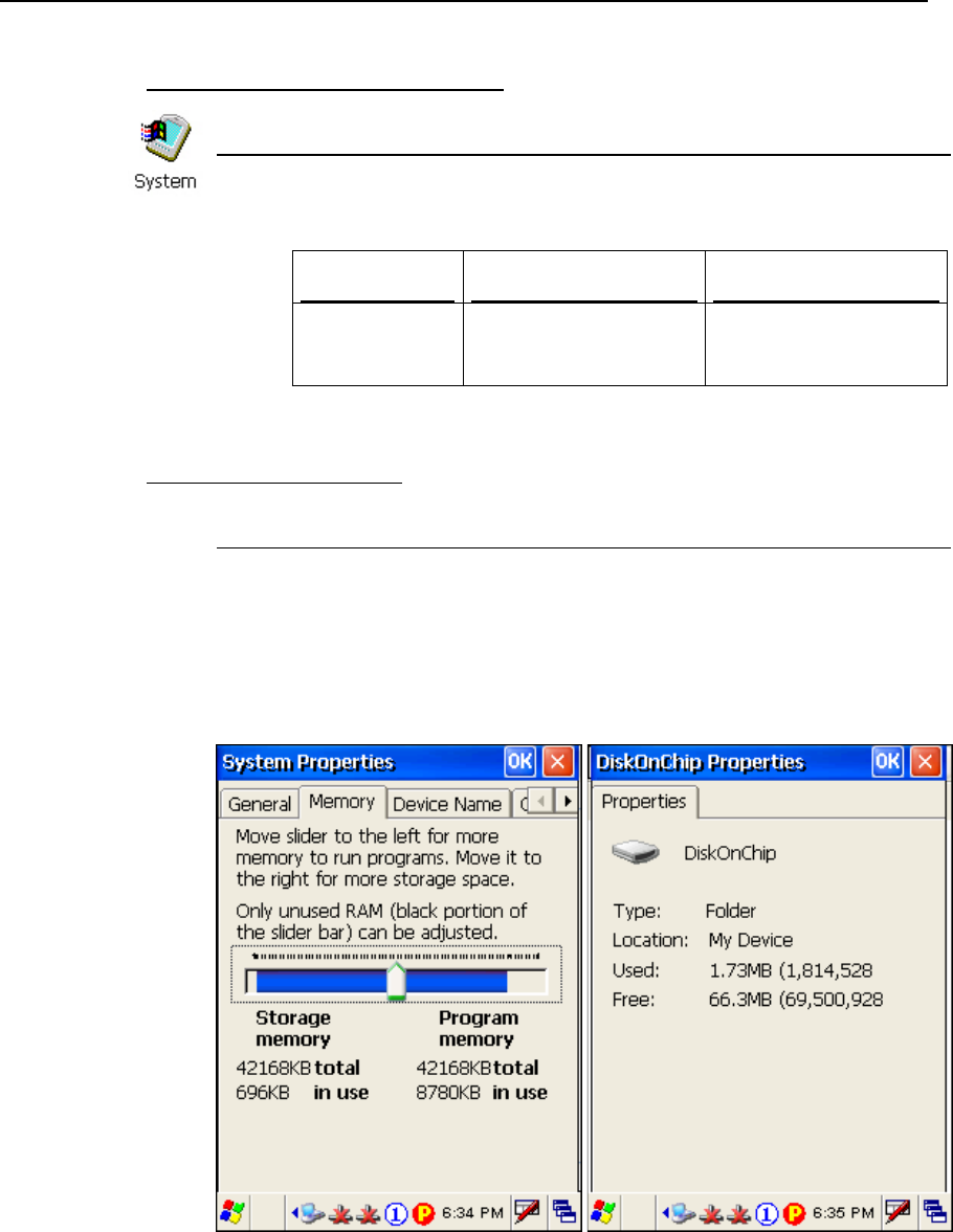
System Properties - Memory tab
Start > Settings > Control Panel and double-tap the System icon
1. In the Memory tab, it displays the current capacity and usage of the 128 MB
onboard SDRAM. (Left below)
2. You may tap, hold, and drag the slider to re-allocate the memory.
SDRAM Storage memory (left) Program memory (right)
128 MB onboard It refers to the memory
allocated for file and data
storage.
It refers to the memory
allocated for running
programs.
DiskOnChip Properties
(Desktop) My Device > DiskOnChip
Tap and hold the DiskOnChip icon and select Properties from the pop-up menu.
In the Properties tab, it displays the current capacity and usage of DiskOnChip. (Right
below)
The DiskOnChip is part of the onboard 128 MB flash memory. Because the flash
memory is non-volatile, data or programs stored in DiskOnChip will not be erased
after a hard reset.
Chapter 1 13
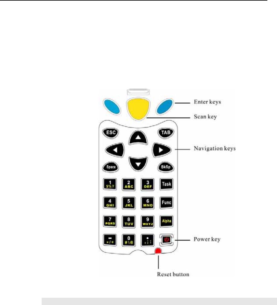
1.5.4 Keypad
The terminal is equipped with a physical keypad that consists of 27 keys. Silicon rubber has
been chosen for their durability and prompt feedback.
The layout of the 27-key keypad includes alphanumeric, assorted characters, etc. This
keypad is set to numeric mode by default.
Figure 4: 27-key layout
Note: Functionality of keys is application-dependent.
14 9500CE Terminal Reference Manual
Keypad Settings
first, and then
The LED backlight of keypad is turned off by default. It can be toggled ON/OFF by
the key combination: [Func] + [0].
Start > Settings > Control Panel and double-tap the Keyboard icon
The Character Repeat functionality is enabled by default. You may cancel the check
box to disable it. When enabled, tap, hold, and drag the slider for a desired Repeat
Delay and Repeat Rate.
Warning: Using backlight while on battery power will substantially reduce battery
life. It is suggested to turn on the keypad backlight while working in a dark
area.
Task Key
The [Task] key on the keypad is set to trigger Windows Explorer.
To launch Windows Explorer, press on the keypad.
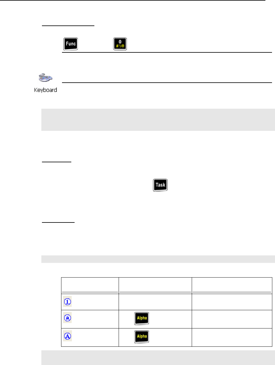
Alpha Key
This alphanumeric keypad is set to numeric mode by default. The Alpha key serves
as a toggle among numeric, alpha (lower-case alphabetic), and ALPHA (upper-case
alphabetic) modes.
Note: It is not necessary to hold down the [Alpha] key.
The alpha icon will appear on the status bar in a sequence as shown below.
Status Icon Alpha Key Input Mode
N/A Numbers
Press one time
Small letters
Press two times
Capital letters
Note: If you are using the software keypad via SIP, tap CAP (Caps Lock) to toggle
between upper case and lower case alphabetic modes.
Chapter 1 15
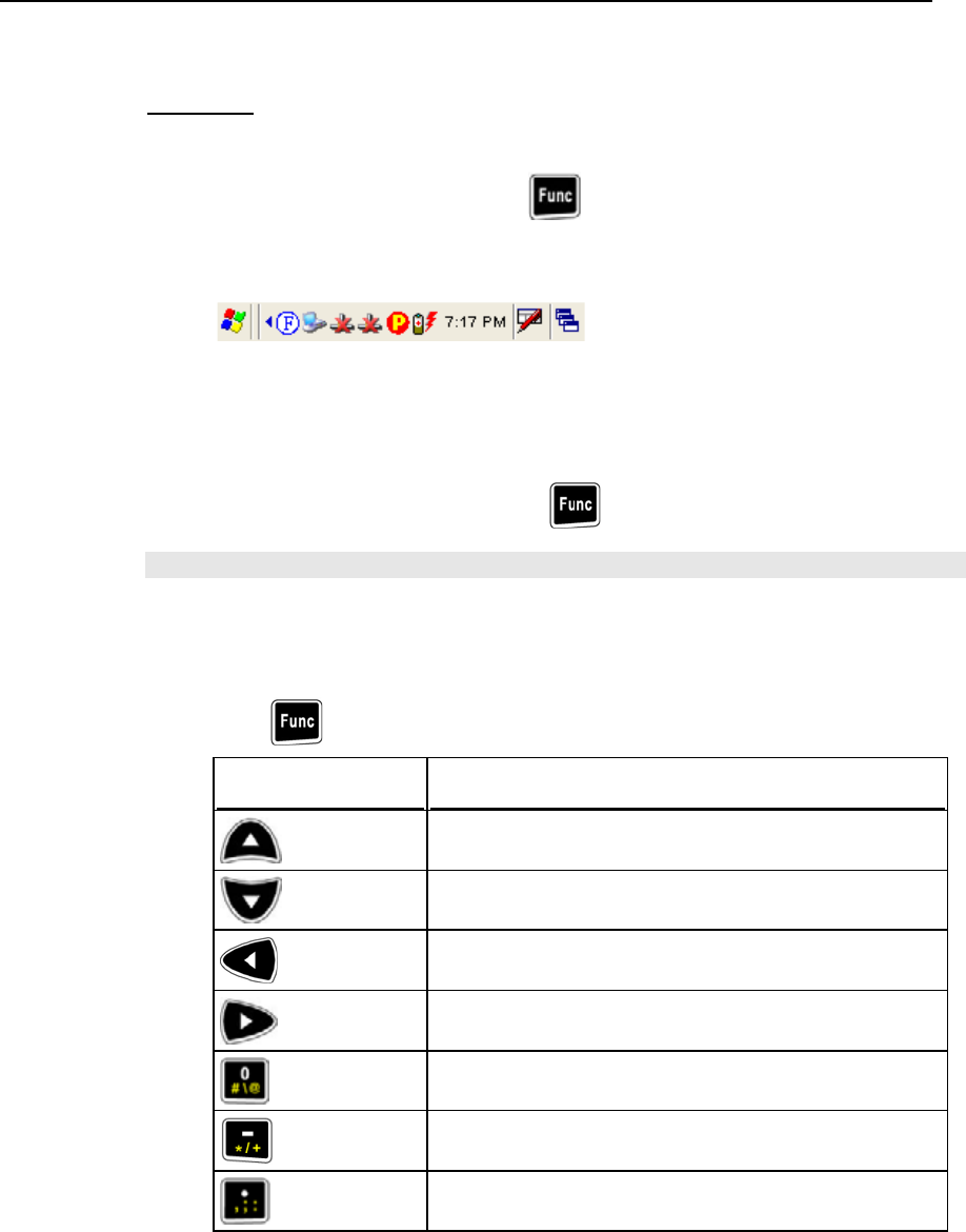
Func Key
The [Func] (function) key serves as a modifier key.
1. To enable this modifier key, press on the keypad.
A circular icon of the letter "F" will appear on the status bar. This modifier key is
hold down as long as the icon is displayed.
2. Now press another key to get the value of key combination (say, press [1] to get the
value of F1). The icon will go off now.
3. To get the value of another key combination modified by the [Func] key, repeat the
above steps.
4. To abort the key modification, press again, and the icon will go off.
Note: It is not necessary to hold down the [Func] key.
The functionality of each key combination is application-dependent. Below is a list
of the factory setting for a variety of key combinations.
Press first, and then press one of the following keys for a specific function:
Key Combination Action
PgUp (red-coded): move text up one screenful
PgDn (red-coded): move text down one screenful
Home (red-coded): move to the beginning of screen or
document
End (red-coded): move to the end of screen or document
Toggle ON/OFF the backlight of keypad only
Turn ON the backlight of LCD and decrease its luminosity
Turn ON the backlight of LCD and increase its luminosity
16 9500CE Terminal Reference Manual
1.5.5 LCD
The terminal comes with a 3.5” TFT graphic LCD, 240 by 320 pixels resolutions. The LED
backlight of screen, which helps ease reading under dim environments, can be controlled
manually and automatically.
Warning: Using backlight while on battery power will substantially reduce battery
life. It is suggested to dim the backlight while working in a well-lit area or
automatically turn off the terminal when not in use.
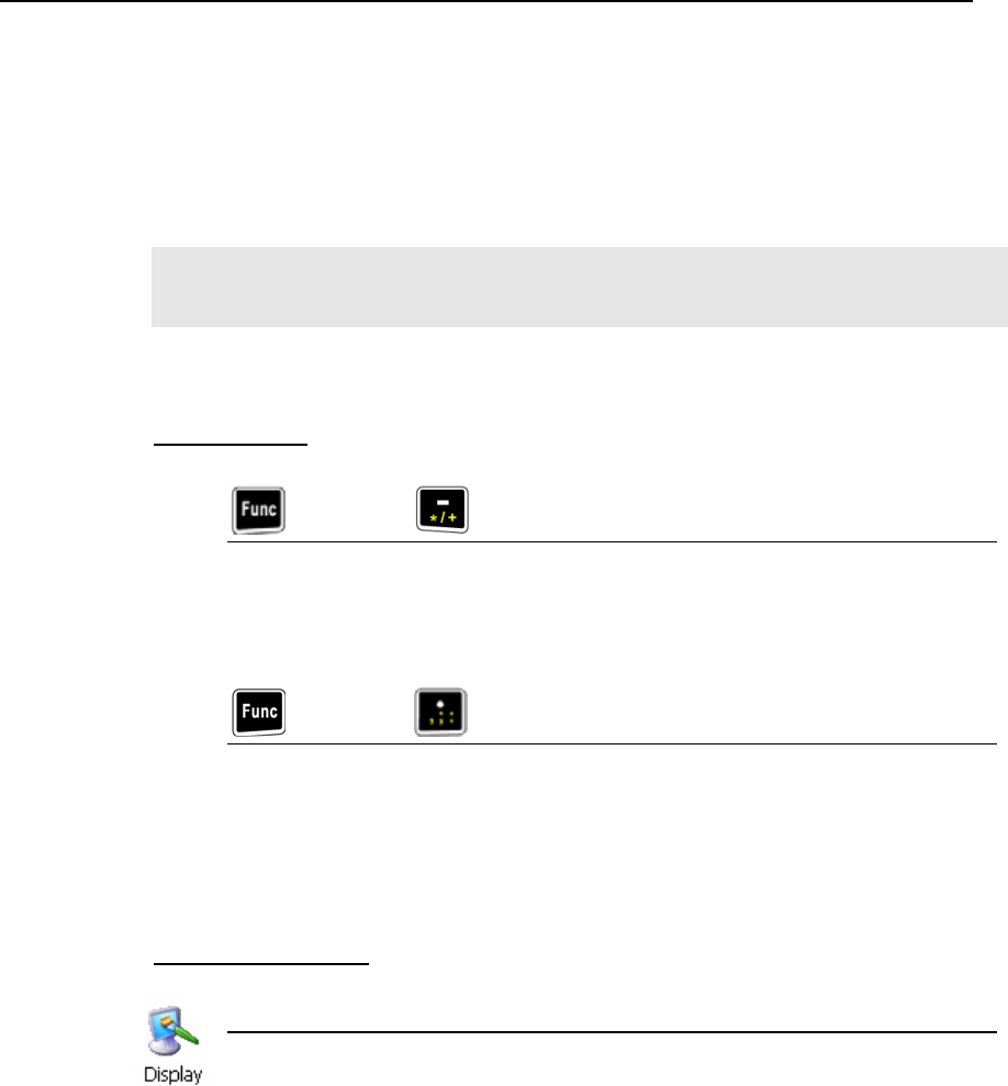
LCD Settings
first, and then
The LED backlight of the screen can be turned on and adjusted decreasingly by the
key combination: [Func] + [–].
It is not necessary to hold down the [Func] key; keep pressing the [–] key until the
luminosity is decreased to a desired level.
first, and then
The LED backlight of the screen can be turned on and adjusted increasingly by the
key combination: [Func] + [•].
It is not necessary to hold down the [Func] key; keep pressing the [•] key until the
luminosity is increased to a desired level.
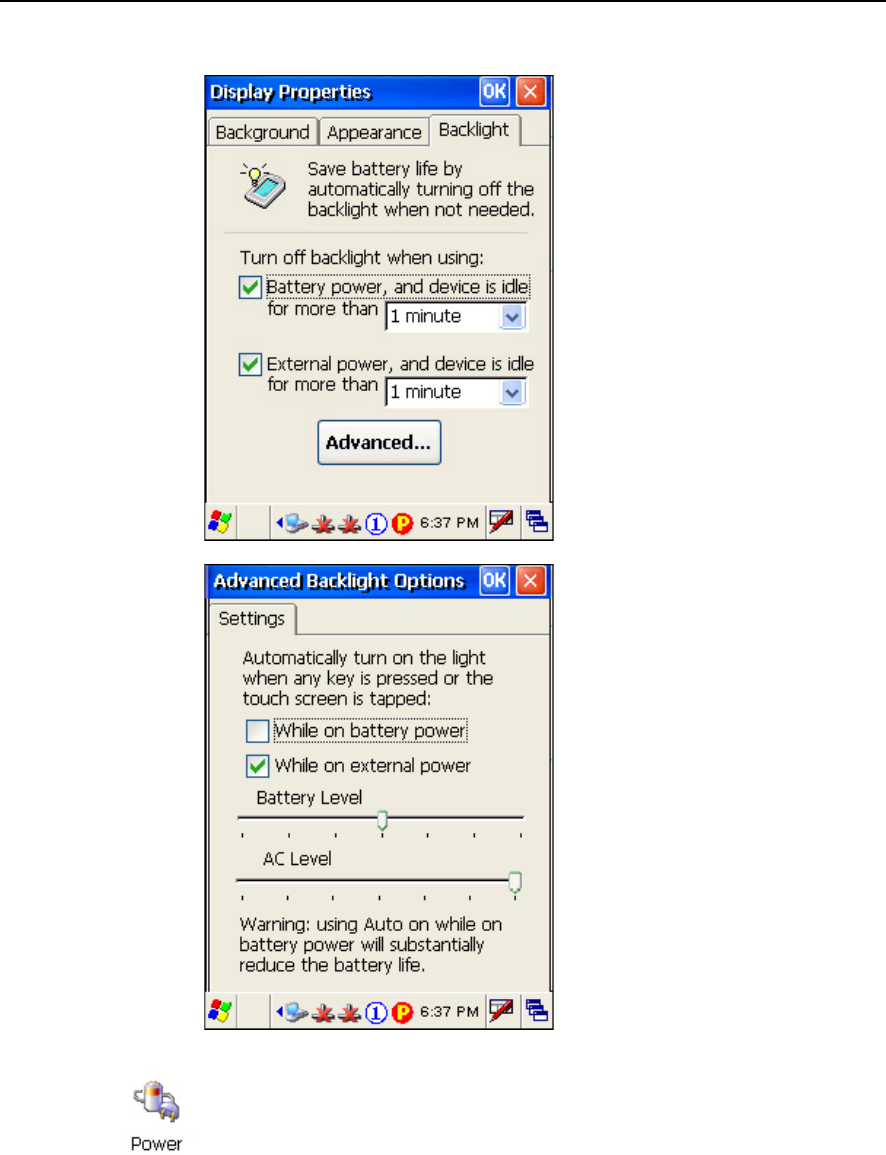
Display Properties
Start > Settings > Control Panel and double-tap the Display icon
1. Tap the Backlight tab. (Left below)
2. Select one or both of the check boxes to automatically turn off the LCD backlight
when using batteries or external power. From the appropriate list, select the
amount of time the device should be idle before the backlight is turned off.
3. Then, tap the [Advanced] button. (Right below)
4. In the Settings tab, you can select the luminosity of backlight when it is set to be
automatically turned on by pressing any key or tapping the screen. Tap, hold, and
drag the slider for AC and battery powered respectively. For more luminosity,
move the slider to the right.
Chapter 1 17
To conserve more power, you may go to Start > Settings > Control Panel and
double-tap the Power icon to configure the power-saving setting.
18 9500CE Terminal Reference Manual
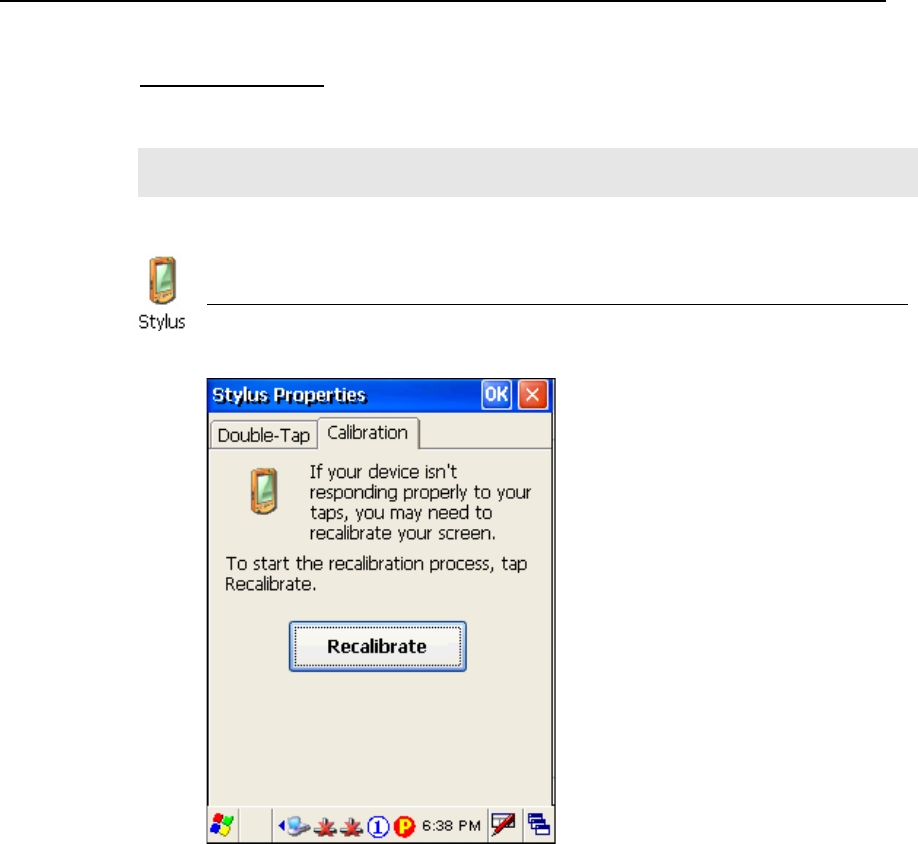
Stylus Properties
This LCD is also a touch screen that can be calibrated through screen alignment.
Warning: DO NOT use any pointed or sharp objects to move against the surface of
the screen.
Start > Settings > Control Panel and double-tap the Stylus icon
1. Tap the Calibration tab.
2. Tap the [Recalibrate] button.

Chapter 1 19
1.5.6 Status LED
The tri-color LED on top of the [Scan] button is used to provide information on status of
battery charging or Bluetooth connection.
Tasks Green LED Red LED Green & Red Blue
Low battery --- Flashing --- ---
Terminal charging --- On --- ---
Charging done On --- --- ---
Charging error --- --- Flashing ---
Bluetooth connection enabled --- --- --- On
1.5.7 Speaker
The speaker, a low power transducer type, can be used for playing sounds applied to events
in Windows and programs, as well as playing audio files such as .WAV files. In addition, it
can be programmed for status feedback.
1.5.8 Vibrator
The terminal is integrated with a vibrator, which is software programmable for feedback.
This can be helpful when working in noisy environments.

20 9500CE Terminal Reference Manual
1.5.9 Reader
A wide variety of scan engines is available for delivering flexibility to meet different
requirements.
Types of Reader Scan Engine
1D Barcode Reader CCD (Long Range Imager)
Laser scan engine
Long Range Laser scan engine
Extra Long Range Laser scan engine (with aiming beam)
2D Barcode Reader 2D scan engine
RFID Tags supported include:
Standard Labels
ISO 14443A Mifare Standard 1K
Mifare Standard 4K
Mifare Ultralight
Mifare DESFire
Mifare S50
SLE44R35
SLE66R35
ISO 14443B SRIX 4K
ISO 15693 ICODE SLI
SRF55V02P
SRF55V02S
SRF55V10P
TI Tag-it HF-I
ICODE® (Phillips) ICODE
Dual Mode Support
The terminal allows the co-existence of one integrated scan engine and the RFID
reader.

Chapter 1 21
Symbologies Enabled
Depending on the scan engine integrated (check the “Active Device” setting in
ReaderConfig), the terminal is capable of scanning barcodes of a number of
symbologies as shown below. If you need to scan barcodes that are encoded in a
different symbology, use the ReaderConfig tool to enable the symbology first.
Active Device Symbologies Enabled
1D Reader The scan engine can be CCD or Laser.
Code 39
Industrial 25
Interleaved 25
Codabar
UPC / EAN
Code 93
Code 128
1D Long
Range Laser
The scan engine can be Long Range Laser or Extra Long Range Laser.
Code 39
Interleaved 25
UPC / EAN
Code 128
RSS-14
2D Reader The scan engine can read linear and 2D barcodes.
Code 39
Interleaved 25
UPC / EAN
Code 128
RSS-14
Postal Codes
PDF417
Data Matrix
MaxiCode
QR Code

22 9500CE Terminal Reference Manual
1.5.10 Wireless Support
The 9500CE Terminal terminal supports state-of-the-art wireless technologies, Bluetooth
and 802.11b/g, so that it is able to send/receive data in real time in an efficient way.
1.5.11 Resistance
Shock
The terminal is designed for harsh industrial environments, and is proved to survive
drop test by the following criteria:
Surface type: concrete
Distance to surface: 1.5 meters
Drop times: multiple
Splash & Dust
The terminal is sealed against moisture and dust to industry standard IP 64.
6 = Totally protected against dust
4 = Protection against water sprayed from all directions. That is, limited ingress is
permitted.
Warning: If additional memory card or peripheral is not factory-installed, the Ingress
Protection rating of enclosures may not be the same as claimed.

23
The terminal is designed for portable use, and it almost requires no installation except
installing the battery pack and necessary auxiliary parts.
Here are some tips and suggestions that ensure safe and comfortable experience with the
terminal.
Warning: Read Important Safety Precautions before installation.
Battery Pack
- Prepare at least one spare battery pack, especially when on the road.
- Be cautious of low battery conditions.
- Turn off the backlight in a bright work area to save battery power.
- Always use proprietary CipherLab batteries for safety concern.
Hand Strap
- The hand strap is ideal for one-handed operation, which requires safe and convenient
hold of the portable terminal.
- Always make sure the hand strap is well hooked and screwed to the back of the
terminal.
Pistol Grip
- This contoured pistol grip enables intuitive trigger-and-scan operation, which is very
helpful in scan intensive applications.
Cradle
- Capable of charging and communications at the same time.
- One terminal seat for terminal with battery pack installed.
- One spare battery compartment for a spare battery pack.
Communications
- Wired, making use of ActiveSync via the USB cradle or directly connecting to
Ethernet networks.
- Wireless, making use of wireless technologies, embedded Bluetooth or 802.11b/g.
CHAPTER 2
Installation
24 9500CE Terminal Reference Manual
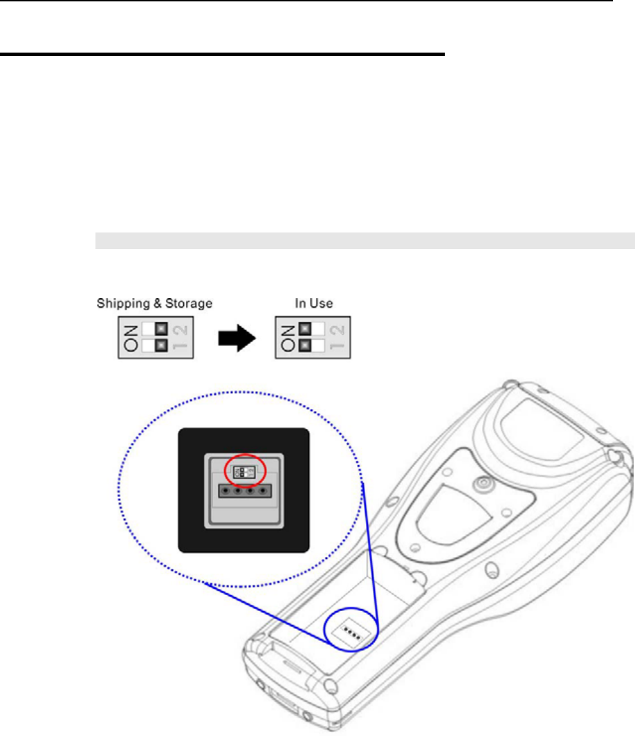
2.1 Main & Backup Batteries
When you first receive the package, the rechargeable functionality of the backup battery is
turned off. It is controlled by a DIP switch inside the battery compartment as shown below.
For shipping and storage purposes, save the terminal and the main battery in separate
packages, and slide the DIP switch to the OFF position (to your right). This will keep both
batteries in good condition for future use.
Note: Any improper handling may reduce the battery life.
Figure 5: DIP switch for backup battery pack
1. Use the stylus (or a sharp-pointed object, such as a pencil) to slide the DIP switch to the
ON position (to your left). Now the internal backup battery can be charged by the main
battery.
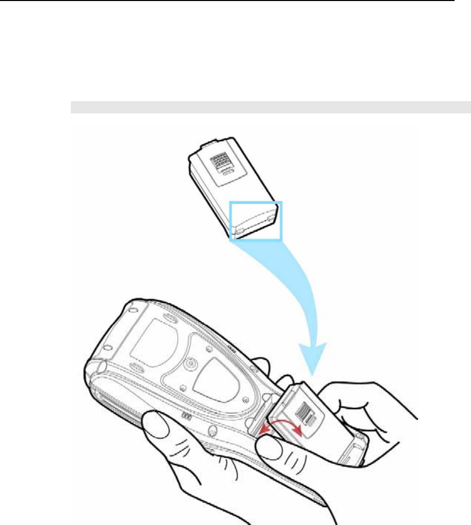
Chapter 2 ʳʳʳʳʳʳʳʳʳʳʳʳʳʳʳʳʳʳʳʳʳʳʳʳʳʳʳʳʳʳʳʳʳʳʳʳ 25
2. Slide the battery pack into the battery compartment at a proper angle (30°~45°) so that
the tabs on the bottom of the battery are hooked in the grooves of the compartment.
Make sure that the battery is snugly fit into the compartment.
3. Hold the terminal still and slide the battery latch to lock the battery in the compartment.
Note: For a new battery, make sure it is fully charged before use.
Figure 6: Installing battery pack
26 9500CE Terminal Reference Manual
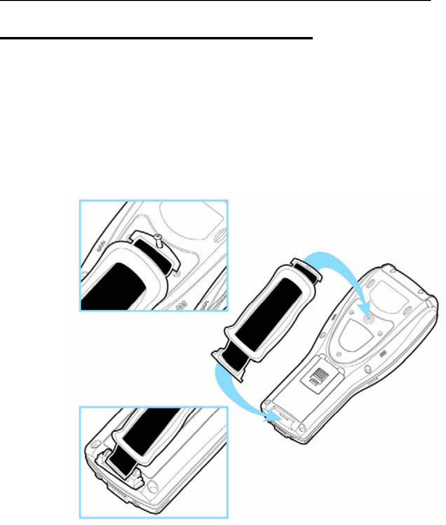
2.2 Hand Strap
When a hand strap is necessary, install it to the terminal by following the steps:
1. Place the terminal face down on a flat and clean surface.
2. Screw one end of the hand strap to the shield-like cover on the back of the terminal.
3. Insert and hook the other end of the hand strap to the bottom of the terminal.
4. Make sure the hand strap is securely attached to the terminal.
5. Adjust the length of the hand strap to suit your handbreadth.
Figure 7: Installing hand strap
Chapter 2 27
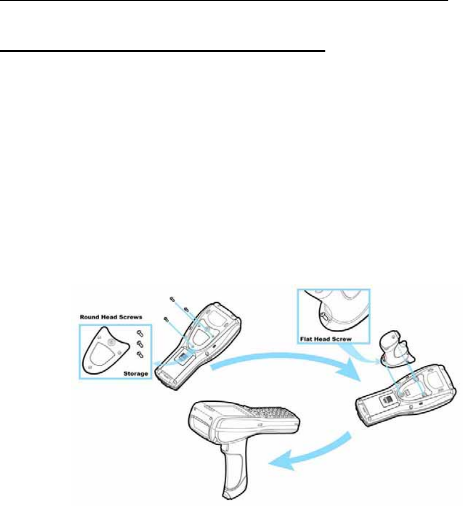
2.3 Pistol Grip
When a pistol grip is necessary, install it to the terminal by following the steps:
1. Place the terminal face down on a flat and clean surface.
2. Remove the shield-like cover on the back of the terminal by unscrewing.
If there is a hand strap installed, remove it first. Keep the cover and screws for future use
when the pistol grip is not desired.
3. Connect the power connector from the pistol grip to the receptacle on the terminal.
4. Screw the pistol grip to the shield-like cover.
5. Make sure all screws are tightened up but not over-tightened to damage the threads.
6. Turn on the terminal and test the trigger.
Figure 8: Installing pistol grip
28 9500CE Terminal Reference Manual
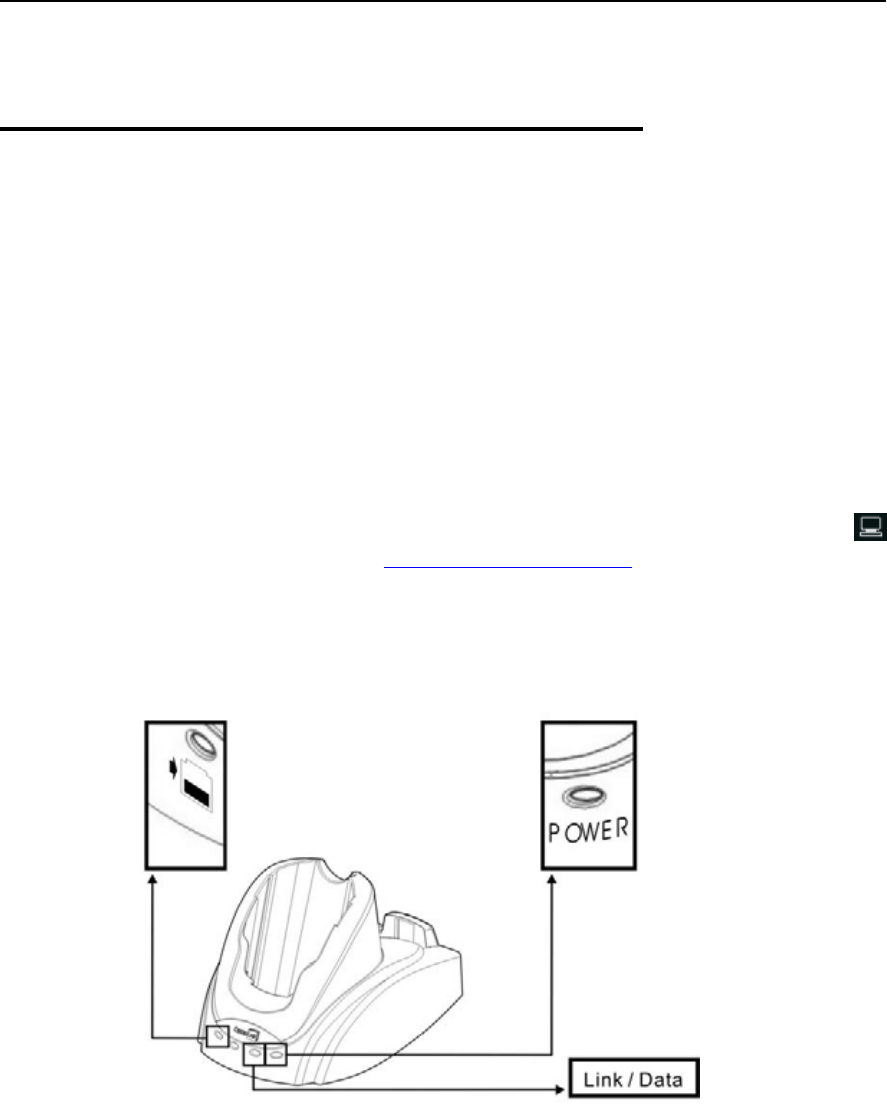
2.4 Cradle
The cradle is designed for charging and communications at the same time.
1. Place the cradle on a flat and clean surface.
2. Connect the line of the power adaptor to the power jack on the back of the cradle.
3. Connect the power adaptor to a suitable power outlet.
4. The cradle is ready for charging the terminal (loaded with main battery) and one spare
battery pack.
Seat the terminal and/or the spare battery pack then.
5. If data communications are desired at the same time, a USB connection must be
established as well. Make sure that you have Microsoft ActiveSync installed on your
computer before you connect the USB cable from the cradle’s USB Client port ( ) to
your computer. Refer to ActiveSync with a Computer.
2.4.1 Status Indicators
Figure 9: Cradle LEDs
Chapter 2 29
Front Panel LEDs Tasks Indication of connection status
Solid red Charging
Solid green Charging done
Flashing (red/green) Error occurs
:
Spare battery
charging status
Off Battery not ready
Solid green Ethernet connected
Link / Data: Network status
over Ethernet Flashing Transmitting / Receiving data
Solid green Power on
POWER: Cradle power
Off Power off
Warning: Charging error may occur due to a power failure or defected battery
contacts.
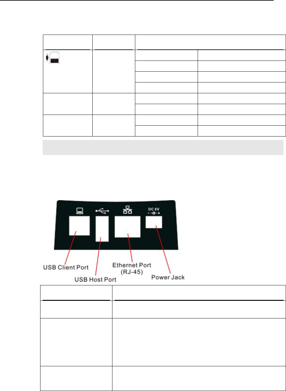
2.4.2 Communication Ports
Ports (from left to right) Purpose
USB Client port This port is provided for connecting to your computer for the use of
ActiveSync application.
USB Host port This port is provided for connecting a USB device:
Keyboard
Mouse
Card reader
Storage device, such as a memory stick
Ethernet port This port is provided for connecting to a legacy network. When
connected, the third LED (next to POWER) will become solid green.
During data transmission, the LED will be flashing.

31
This chapter mainly describes the basic skills to work with the 9500CE Terminal terminal.
The add-on utilities for applications regarding data collection, processing, and transmission,
are introduced in the following chapters.
The 9500CE Terminal terminal is specifically designed for real-time data collection in the
Windows CE 5.0 environment. It won't take long for any Windows user to get familiarized
with it. Keep these two basic skills in mind and explore this Windows CE device at ease.
Double-tap an item to select it.
Tap and hold an item to see a menu that enables tasks, such as cut, copy, rename, delete,
etc.
Tap and drag to select multiple items.
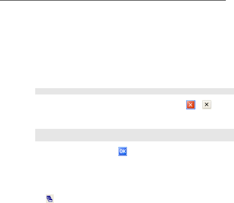
To close an active window, a dialog box, or a running application, tap or when it is
available on the toolbar. If the Close button is not displayed, press [ESC] on the physical
keypad to exit.
To save current settings and exit, tap when it is available on the toolbar.
CHAPTER 3
Windows CE Basics

32 9500CE Terminal Reference Manual
3.1 General
When the 9500CE Terminal terminal is fully charged, you may remove it from the cradle.
Then turn on the terminal and wait for the Windows CE desktop to come up.
If you are using the terminal for the first time, there are a couple of things to do after the
desktop comes up.
To select your time zone and set the local time: Start > Settings > Control Panel, and
double-tap the Date/Time icon.
To align the touch screen: Start > Settings > Control Panel, and double-tap the Stylus
icon.
To obtain essential system information, go to Start > Settings > Control Panel, and
double-tap the System icon. Select the Device Name tab to change the identification for
the terminal.

Chapter 3 ʳʳʳʳʳʳʳʳʳʳʳʳʳʳʳʳʳʳʳʳʳʳʳʳʳʳʳʳʳʳʳʳʳʳʳʳʳʳʳʳʳʳʳʳʳ33
3.1.1 Device Configuration
The device configuration of 9500CE Terminal is displayed in 5 digits: xxxx-x
Take the screenshot of System Properties above for example. Its device configuration is
“5410-0”, which means the 27-key terminal has equipped with the following parts:
A scan engine that employs extra long range laser
An integrated Bluetooth module and an optional Wi-Fi module
An RFID reader
Device Code Modular Component Types
1st digit Reader module 0= none
1= CCD scan engine
2= Laser scan engine
3= 2D scan engine
4= Long Range Laser scan engine
5= Extra Long Range Laser scan engine
2nd digit Wireless module 4= Bluetooth + 802.11b/g
5= Bluetooth only
3rd digit RFID module 0= none
1= RFID reader
4th digit Reserved ---
5th digit Keypad module 0= 27-key
34 9500CE Terminal Reference Manual
3.1.2 Turn On/Off
Like your PDA, Pocket PC and most handheld devices, the 9500CE Terminal terminal
functions when it is turned on. This is because the Windows CE operating system
eliminates the booting process and runs continuously.
Turn On (= Resume from Suspend)
To turn on the terminal, simply press the [Power] key.
Turn Off (= Suspend)
To turn off the terminal, press the [Power] key again, or select Suspend from the Start Menu.
The system is now ready for use but not in use. This is referred to as Suspend mode or Standby
mode. It means the system is in power-saving status and waiting for user interference.
Warning: To save battery power, it is suggested that the terminal is set to be
automatically turned off when not in use. Refer to the Power Management
section for more information about saving power.
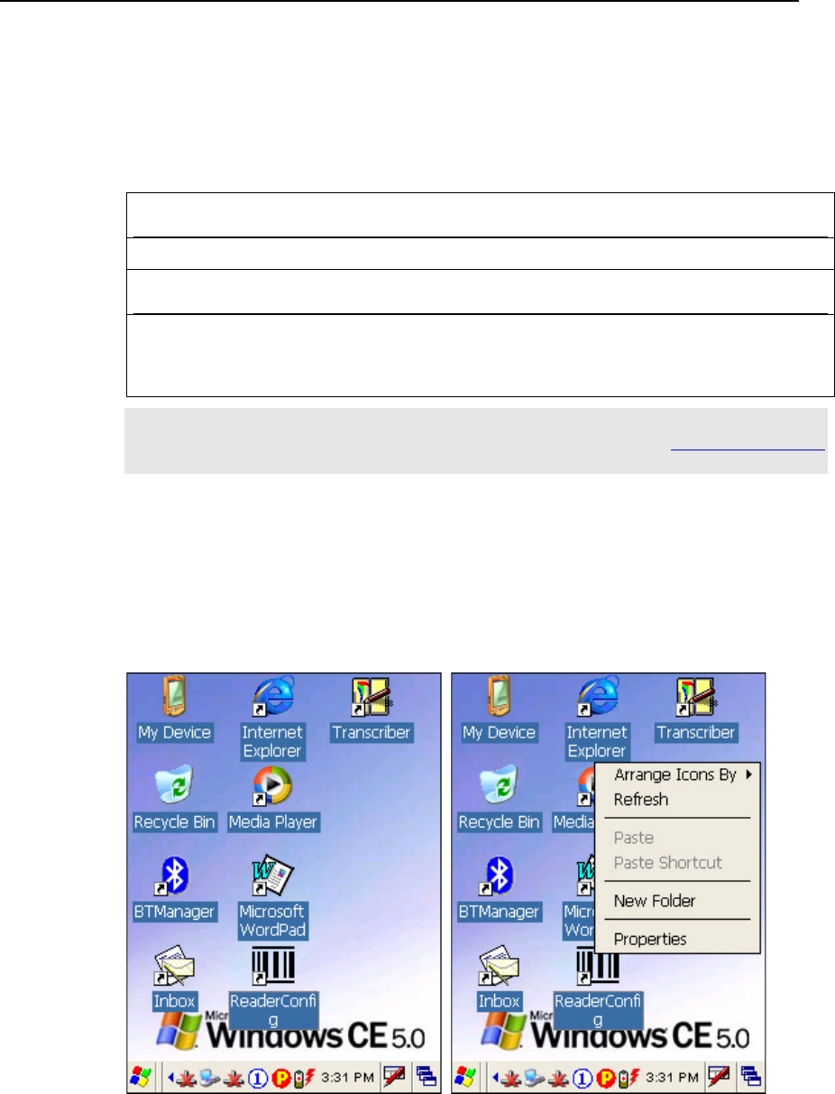
3.1.3 Desktop Window
The desktop appears when the terminal is turned on (left below). Tap and hold on the blank
area to manage or configure the desktop (right below).
Chapter 3 35
Alternatively, you may tap to the right of the taskbar, and then select Desktop.
Note: To customize the desktop, tap on the blank area of desktop and select Properties.
When you turn on the terminal and seat it in the cradle for the first time, you will find the
following icons displayed on the taskbar:
: This icon shows that your cradle is directly connected to a computer via USB port.
Make sure you have Microsoft ActiveSync installed on your computer.
: There will be two of this icon, one is for BTPAN1 disabled, the other for AX88772
(Ethernet) disabled.
:This icon is a shortcut to the Wireless Power Manager that controls the power to
802.11b/g modules.
: This icon shows that the charging progress is ongoing.
: This icon shows that numeric mode is in use for data input via keypad.
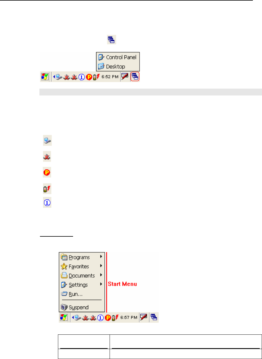
Start Menu
Tap the Start button on the taskbar to open the Start Menu.
Options Description
Programs Provides access to available programs in the directory:
36 9500CE Terminal Reference Manual
\Windows\Programs
Favorites Provides access to your favorites in the directory:
\Windows\Favorites
Documents Provides access to recent opened documents in the directory:
\Windows\Recent
Settings Provides access to
Control Panel
Network and Dial-up Connections
Taskbar and Start Menu
Run… Runs a program or application.
Suspend Enters the Suspend mode.
Note: To configure the Start menu and taskbar, go to Start > Settings and select Taskbar
and Start Menu.
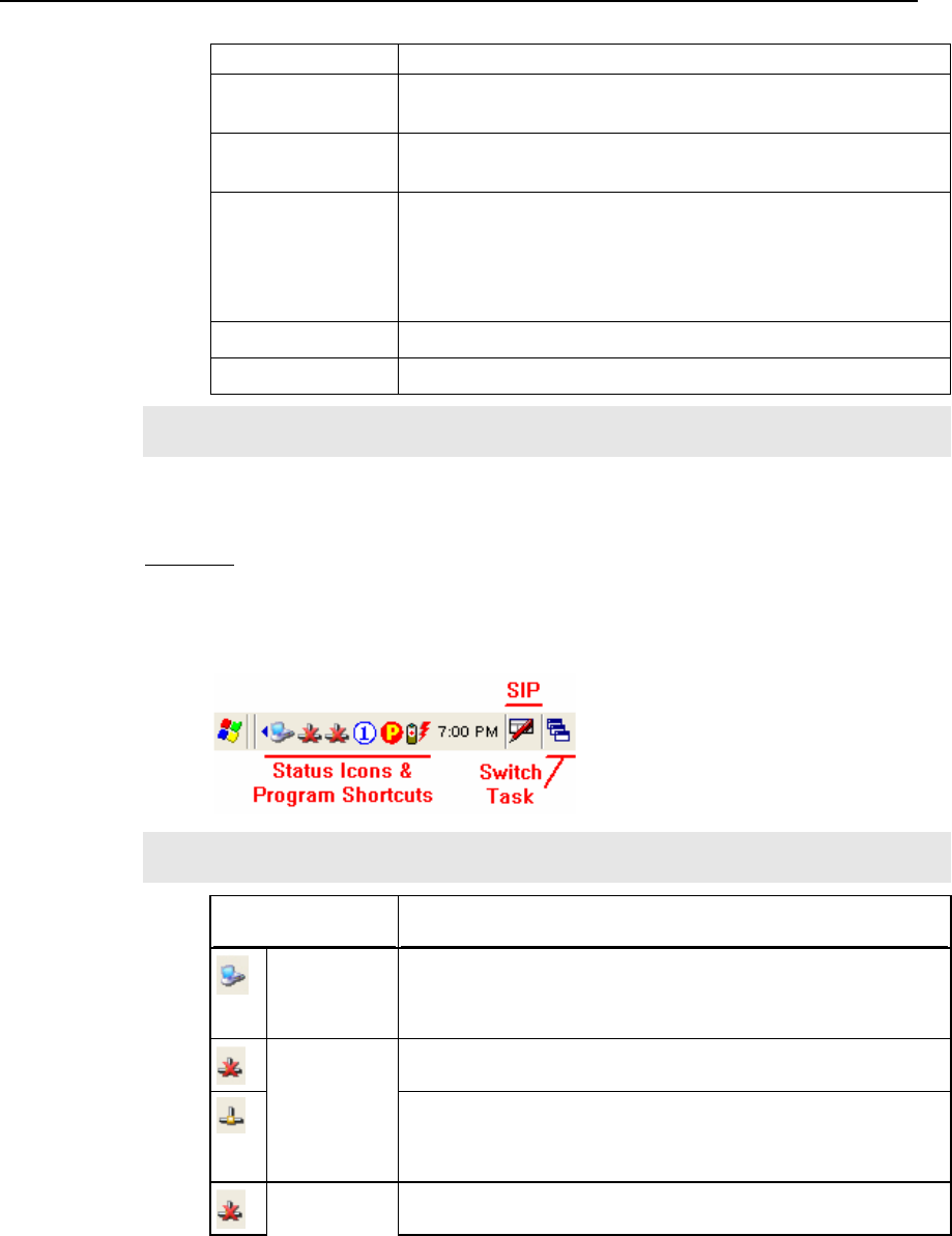
Taskbar
The taskbar is at the bottom of the screen for displaying the Start button, up to 6
status icons for various connections or programs, SIP button, Switch Task button,
etc.
Note: To configure different connections, go to Start > Settings and select Network and
Dial-up Connections.
Icons Description
Connected via
USB
The USB connection for ActiveSync operation is successfully
established.
Double-tap it to view status. Tap [Disconnect] if necessary.
The Bluetooth PAN connection fails. (= disconnected)
BTPAN1
The Bluetooth PAN connection is successfully established through
the Bluetooth Manager utility.
Double-tap it to view or renew IP Information.
Ethernet via The Ethernet connection via AX88772 fails. (= disconnected)
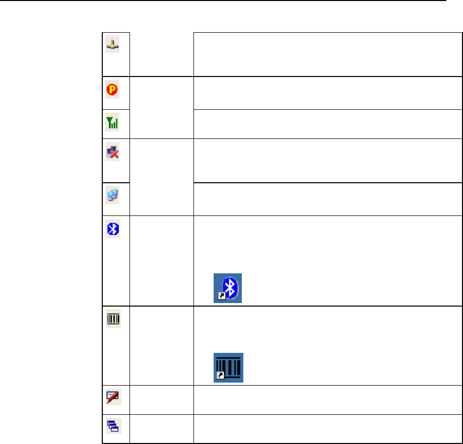
Chapter 3 37
cradle The Ethernet connection via AX88772 is successfully established
once the Cat. 5 cable is connected.
Double-tap it to view or renew IP Information.
It provides control of the power to the 802.11b/g.
Double-tap any of these icons to configure the power setting.
Wireless
Power
Manager
It indicates the Wi-Fi module (802.11b/g) is enabled. See WLAN1
status icons below.
The Wi-Fi connection fails. (= disconnected)
Double-tap it to access the Wireless Information tab for
establishing a new connection.
WLAN1
The Wi-Fi connection is successfully established.
Double-tap it to view or renew IP & Wireless Information.
Bluetooth
Manager
It provides access to the Bluetooth services.
Initially, you need to double-tap the Bluetooth Manager
shortcut on the desktop so that this icon will appear on the
taskbar.
ReaderConfig It provides access to the reader configuration utility.
Initially, you need to double -tap the ReaderConfig shortcut on
the desktop so that this icon will appear on the taskbar.
Software Input
Panel (SIP)
Tap it to change input method.
Switch Task Tap it to switch to desktop or any task, such as a running program or
window.
38 9500CE Terminal Reference Manual
3.1.4 Input Methods
Data entry can be performed by the following methods:
Type with the 27-key physical keypad
Scan barcode or RFID tag in applications, e.g. WordPad, CipherLab’s Application
Generator, etc.
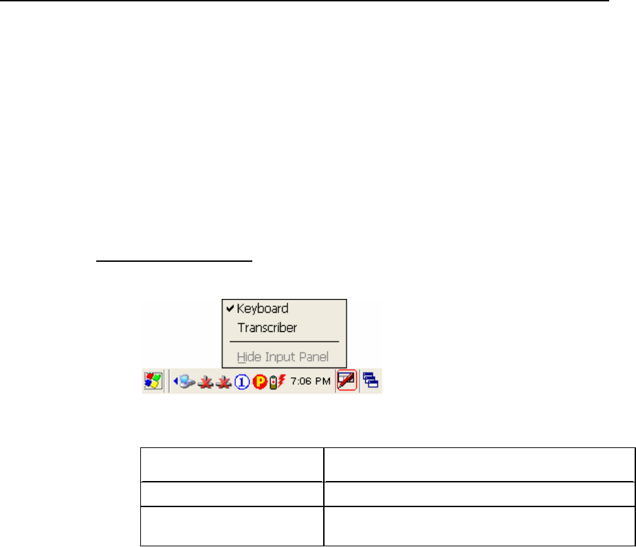
Tap or write using SIP (Soft Input Panel)
Soft Input Panel (SIP)
Tap the SIP button on the taskbar to select a SIP mode or hide the input panel.
In each mode, the characters appear as typed text on the screen.
SIP Options Action
Keyboard To type using the virtual keyboard.
Transcriber To write freely on the screen in applications, such as
WordPad, Inbox, etc.
Chapter 3 39
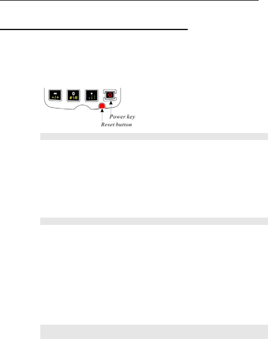
3.2 System Reset
Reset the 9500CE Terminal terminal when it stops responding to input.
Soft reset: Simply press the [Reset] button.
Hard reset: Press the [Reset] button and the [Power] key at the same time.
Warning: Never perform a hard reset unless a soft reset cannot solve your problems.
3.2.1 Soft Reset
A soft reset, also known as a warm boot, will restart the terminal and keep all the saved files.
To perform a soft reset, use the stylus to press the [Reset] button.
During operation, the removal of battery pack will start a soft reset too.
Warning: Data loss may occur when files are not properly closed before a soft reset.
3.2.2 Hard Reset
A hard reset, also known as a cold boot, will restart the terminal too. However, it performs a
full restore of the terminal to its factory settings and initializes SDRAM. To perform a hard
reset, press the [Power] key and [Reset] button at the same time.
Data and program files stored in SDRAM will be erased after a hard reset. But you can
restore data that is previously synchronized with your computer by performing an
ActiveSync operation.
Warning: Only the files stored in the Flash File System are retained during a hard
reset.
40 9500CE Terminal Reference Manual
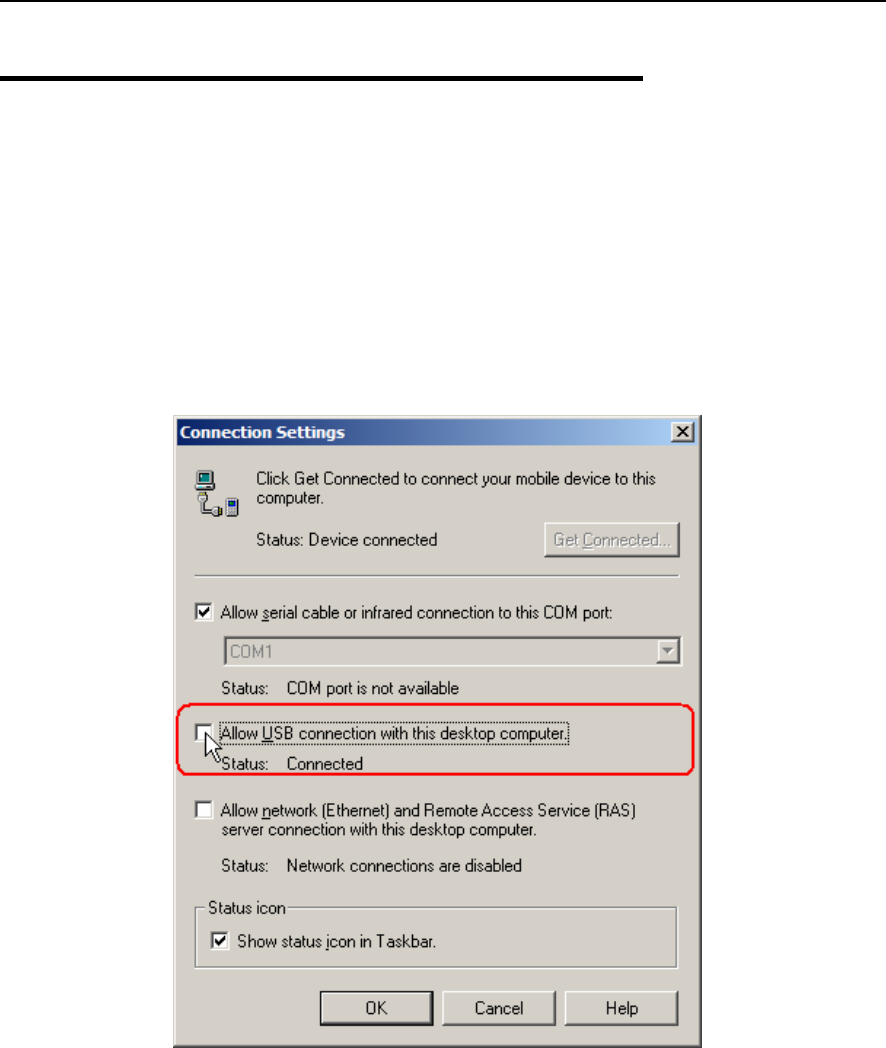
3.3 Firmware Update
Firmware update should be performed with great caution because everything on the
terminal will be erased. Backup user-installed applications and files to your computer first.
The firmware update utility is available on the CD-ROM. To re-install or upgrade the
operating system (image file) on your terminal, run the installer “AP.exe” from the
CD-ROM. It will create a shortcut of the program “DLDR.exe” on the desktop of your
computer.
1. Install Microsoft ActiveSync on your computer. Refer to section 3.4 for initial
ActiveSync operation. Then, disable the ActiveSync operation as shown below.
2. Run the installer “AP.exe” from the CD-ROM.
3. Perform a hardware reset on the 9500CE Terminal terminal.
4. For the terminal to enter the “Download” mode, press [Space] + [8] + [Power]
simultaneously in three seconds.
5. Seat the terminal in the cradle.
6. Run the Image Download program (DLDR.exe) on your computer.

Chapter 3 41
7. Press [Enter] on the terminal to start image update.
It will take approximately 5 minutes to update the image. A message will be displayed
on the terminal to indicate the firmware update is completed successfully.
8. Perform a hardware reset on the terminal again.
Warning: Do not press any key on the terminal while updating OS image.
Once firmware update is completed, you cannot reload any older image.
3.4 ActiveSync with a Computer
ActiveSync is used to synchronize information between the terminal and PC, to install
programs on the terminal, and to backup and restore the terminal.
The Microsoft ActiveSync program has to be installed on your desktop computer first.
To download the up-to-date version of the program, you may need to go to Microsoft's
official web site for Windows Mobile devices as shown below.
http://www.microsoft.com/windowsmobile/default.mspx
After downloading and installation, run the program.
For detailed information on the program, you may click the Help menu, and then select
the Microsoft ActiveSync Help.
Note: We recommend that you have ActiveSync 3.7.1 installed on your computer because
ActiveSync 4.x does not officially support Windows CE 5.0 devices.
1. Follow these instructions for initial ActiveSync operation:
Connect the USB cable from the cradle’s USB Client port ( ) to your computer.
Connect the power cable from the cradle to a nearby power outlet.
Turn on the 9500CE Terminal terminal and seat it in the cradle.
2. Your computer will automatically detect the USB device. Click [OK] when the
connection is established.
3. Select which partnership to set up.
If you want to synchronize data between 9500CE Terminal and your computer, select
Standard Partnership; otherwise, select Guest Partnership.
4. Wait a few seconds for 9500CE Terminal to get connected (and synchronized if a
Standard Partnership is selected).
42 9500CE Terminal Reference Manual
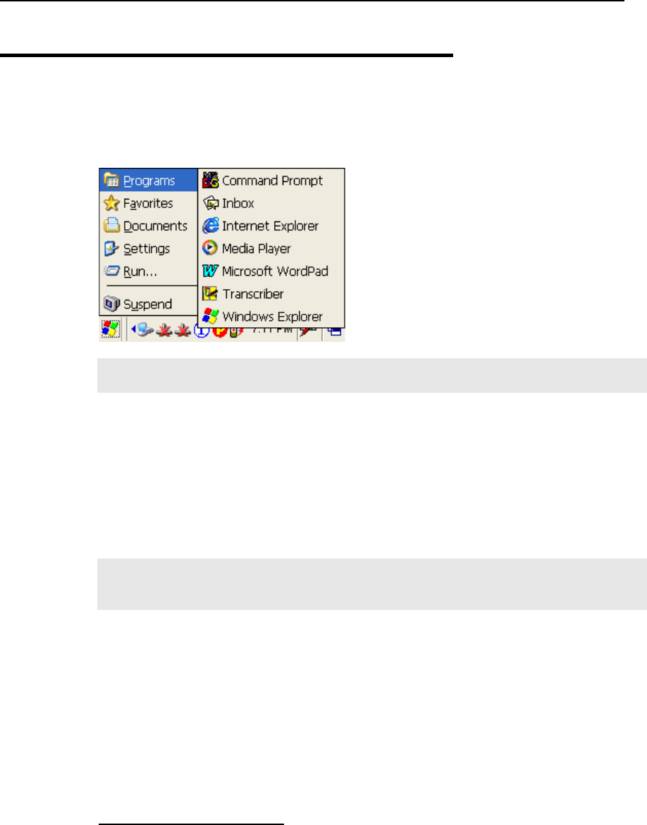
3.5 Quick Launch a Program
Tap the Start button to view the Start Menu. To quick launch a program, tap it from the
Programs folder.
Note: Alternatively, you may tap Start and select Run to run a specific program or open a
document.
To add a new program or subfolder to the Programs folder, you can either use Windows
Explorer or ActiveSync.
Windows Explorer: to move the program by [Copy] and [Paste Shortcut].
ActiveSync on the desktop computer: to create a shortcut to the program, and place the
shortcut in the Programs folder.
Warning: To avoid making any changes to the program configurations by accident,
we recommend you to use [Copy] and [Paste Shortcut] rather than [Cut]
and [Paste].
3.5.1 Add a Program
If you wish to quick launch a new program, add it to the Programs folder: My
Device\Windows\Programs
Using Windows Explorer
1. Go to Start > Programs, and select Windows Explorer. Alternatively, you can press
the [Task] key on the keypad to launch Windows Explorer.
2. Navigate through file folders to find the program you desire.
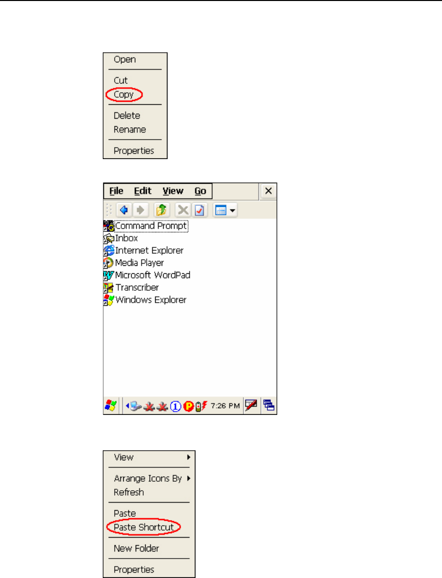
Chapter 3 43
3. Tap and hold the program, and then tap [Copy] on the pop-up menu.
4. Navigate to the Programs folder (My Device\Windows\Programs).
5. Tap and hold anywhere blank on the screen. Then tap [Paste Shortcut] on the pop-up
menu. The new program will be added to the Programs folder.
6. Go to Start > Programs and the new program will appear now.
44 9500CE Terminal Reference Manual
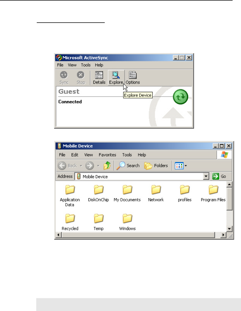
Using ActiveSync on PC
1. When connected, open the Microsoft ActiveSync window on your desktop
computer.
2. Click the Explorer button from the toolbar.
3. Navigate through file folders to find the program you desire.
4. Right-click the program, and then select [Create Shortcut] on the pop-up menu.
5. Right-click the shortcut, and then select [Cut] on the pop-up menu.
6. Navigate to the Programs folder (My Device\Windows\Programs).
7. Right-click anywhere blank on the window. Then select [Paste] on the pop-up menu.
The new program will be added to the Programs folder.
8. On the terminal, go to Start > Programs and the new program will appear now.
Note: [Create Shortcut], [Cut], and [Paste]: The same result can be performed by [Copy]
and [Paste Shortcut].

Chapter 3 45
3.5.2 Add a Subfolder
Using Windows Explorer
1. Go to Start > Programs, and select Windows Explorer. Alternatively, you can press
the [Task] key on the keypad to launch Windows Explorer.
2. Navigate through file folders to find where you wish to create a new folder.
3. Right-click anywhere blank on the window, and select [New Folder] from the
pop-up menu. A subfolder will be created.
Using ActiveSync on PC
1. When connected, open the Microsoft ActiveSync window on your desktop
computer.
2. Click the Explorer button from the toolbar.
3. Navigate to the target folder where you wish to create a new folder.
4. Right-click anywhere blank on the window, and select [New Folder] from the
pop-up menu. A subfolder will be created.
46 9500CE Terminal Reference Manual
3.5.3 Exit a Program
In general, the system manages memory automatically, and there is no need to exit a
program in order to open another or to conserve memory. However, random access memory
(SDRAM) may be used up when running too many programs. As a result, it will slow down
the operation or cause program errors. In that case, you should stop one or more running
programs to free memory.
In order to use memory in a more efficient way, you are recommended to exit a program
when it is not desired any longer.
Warning: Always remember to save data or settings before you exit a program.
To close an active window, a dialog box, or a running application, tap or when it is
available on the toolbar. If the Close button is not displayed, press [ESC] on the physical
keypad to exit.
Note: Some programs, such as the Bluetooth Manager, may create an associated icon on
the taskbar. You may tap the icon and select [Exit] from the pop-up menu.
To save current settings and exit, tap when it is available on the toolbar.
3.5.4 Switch between Programs
Tap to the right of the taskbar, and then select a running program.
Chapter 3 47
3.6 Install a New Program
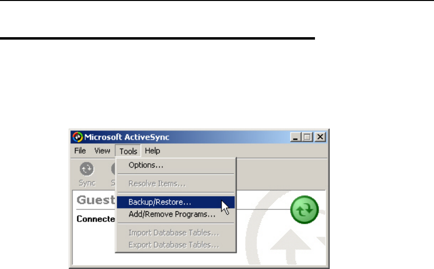
3.6.1 Add/Remove Programs
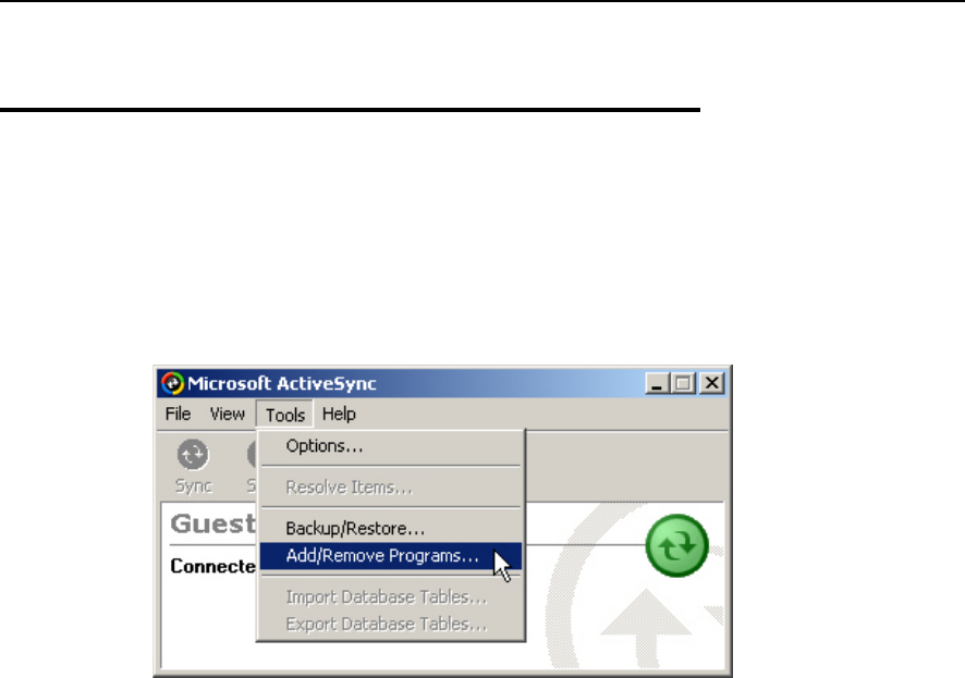
To install a program that is designed to be used on a mobile device running Windows CE,
you may click [Add/Remove Programs] from the Tools Menu.
3.6.2 Copy & Paste
Alternatively, you may install a new program manually.
1. When connected, open the Microsoft ActiveSync window on your desktop computer.
2. Click the Explorer button from the toolbar.
3. Navigate to the target folder, e.g. the Programs folder, depending on where you wish to
access the program.
4. Navigate through file folders on your computer to find the new program.
5. Right-click the program and select [copy] on the pop-up menu.
6. Back to the target folder in step 3. Right-click anywhere blank and select [Paste] on the
pop-up menu.
7. On the terminal, go to Start > Programs and the new program will appear.
48 9500CE Terminal Reference Manual
3.7 Uninstall a Program
If a user program is no longer desired, you may remove it from the system.
3.7.1 ActiveSync: Add/Remove Programs
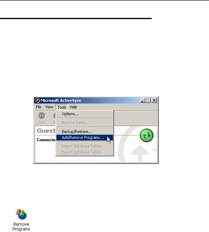
To uninstall a program that is designed to be used on a mobile device running Windows CE,
you may click [Add/Remove Programs] from the Tools Menu.
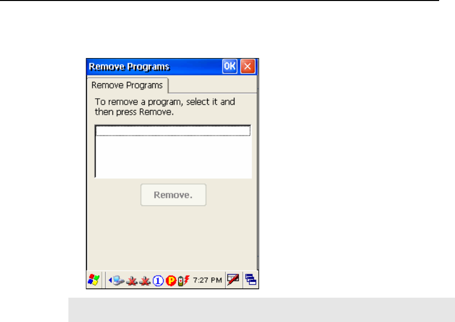
3.7.2 Control Panel > Remove Programs
Alternatively, you may uninstall a new program manually.
1. Go to Start > Settings > Control Panel, and double-tap the Remove Programs icon.
2. Tap the name of the program that you want to delete.
3. Tap [Remove].
4. Tap [Yes] to uninstall the program.
Chapter 3 49
Note: If the program does not appear in the list of installed programs, you may use
Windows Explorer to locate it. Tap and hold the program, and select [Delete].
50 9500CE Terminal Reference Manual
3.8 Backup & Restore Programs
To best protect your work, you should regularly back up information on your terminal. You
can perform a backup by during the ActiveSync operation. The backup file is stored on your
desktop computer.
51
In this chapter, a brief on the system settings is provided for your reference.
Note: User settings are stored in SDRAM and will be overwritten by the system defaults
after a hard reset.
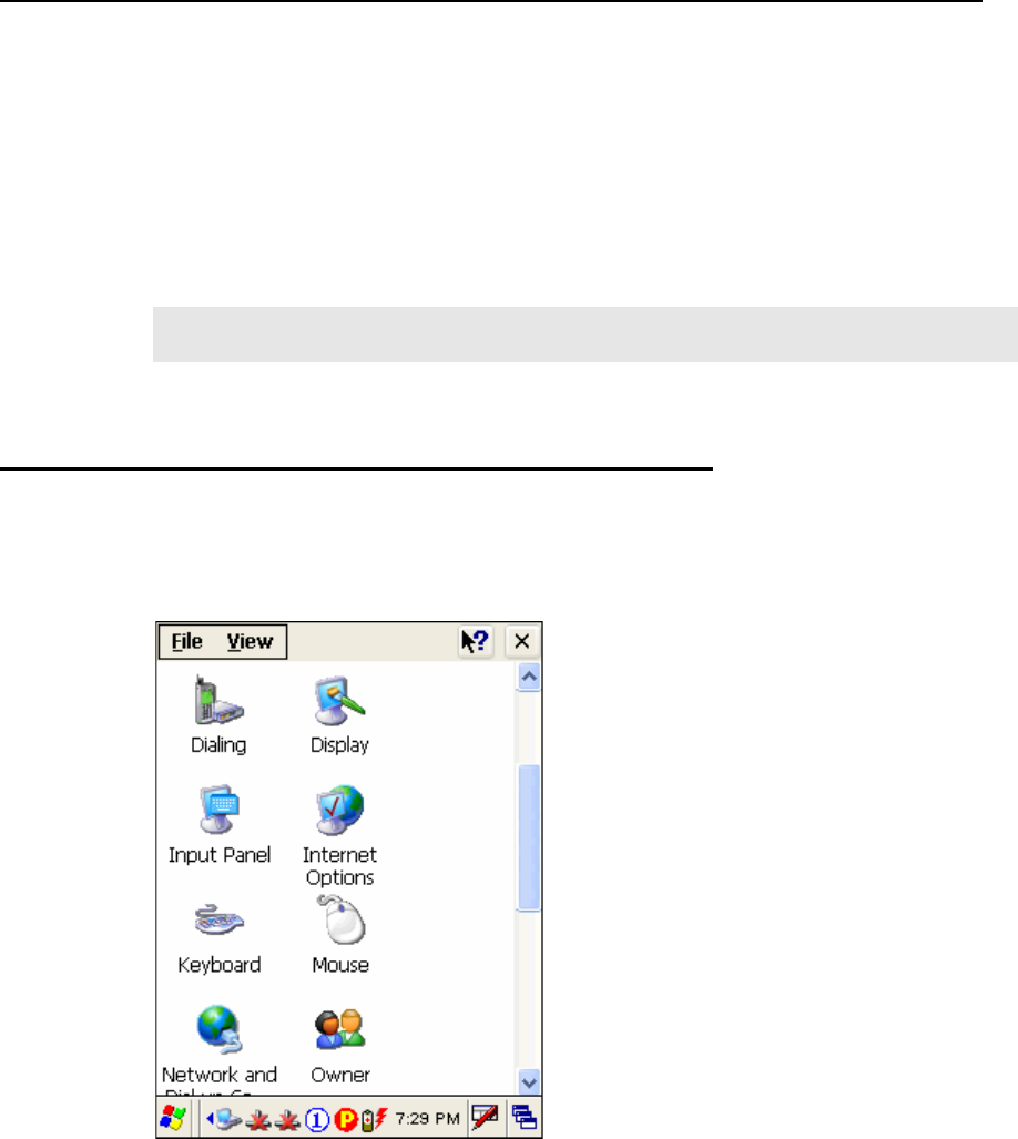
4.1 General Settings
Go to Start > Settings > Control Panel.
CHAPTER 4
Configuration
52 9500CE Terminal Reference Manual
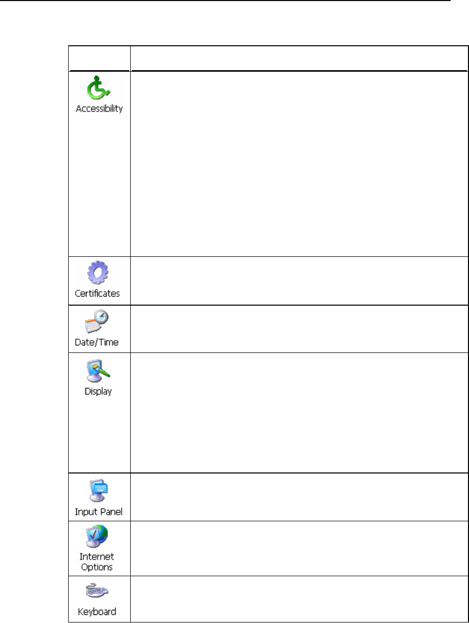
Items Description
In the [Accessibility] dialog box, you may use these options to customize the way an
external keyboard, display, or mouse functions. Many of these features are useful to
people without disabilities
Keyboard tab: Select StickyKeys to enable simultaneous keystrokes while
pressing one key at a time; select ToggleKeys to emit sounds when certain
locking keys are pressed.
Sound tab: Select SoundSentry to provide visual warnings for system sounds.
Display tab: Select High Contrast to improve screen contrast with alternative
colors.
Mouse tab: Select MouseKeys to enable the keyboard to perform mouse
functions
General tab: Select Automatic Reset if you wish to turn off accessibility features
after a specific period of time; select Notification if you wish to hear a sound
when turning a feature on or off.
In the [Certificates] dialog box, you may view or modify digital certificates that some
application use to establish trust for secure connections.
In the [Date/Time] dialog box, you may change date, time, and time zone settings.
In the [Display Properties] dialog box,
Background tab: Select an image for the background.
Appearance tab: Select a desired color scheme for windows, dialog boxes, and
items.
Backlight tab: Specify for how long the terminal is idle and then the backlight
will be automatically turned off while on battery power and external power (in
the charging cradle) respectively. Tap the [Advanced] button to move the slider
and adjust the brightness of the LCD backlight when it is set to be automatically
turned on once a key is pressed or you tap the touch screen.
In the [Input Panel Properties] dialog box, you may configure how the Soft Input
Panel (SIP) works.
In the [Internet Options] dialog box, you may configure how the terminal connects to
the Internet.
Connect an external keyboard to the cradle via the USB Host port.
In the [Keyboard Properties] dialog box, you may configure settings for character
repeat.
Chapter 4 53
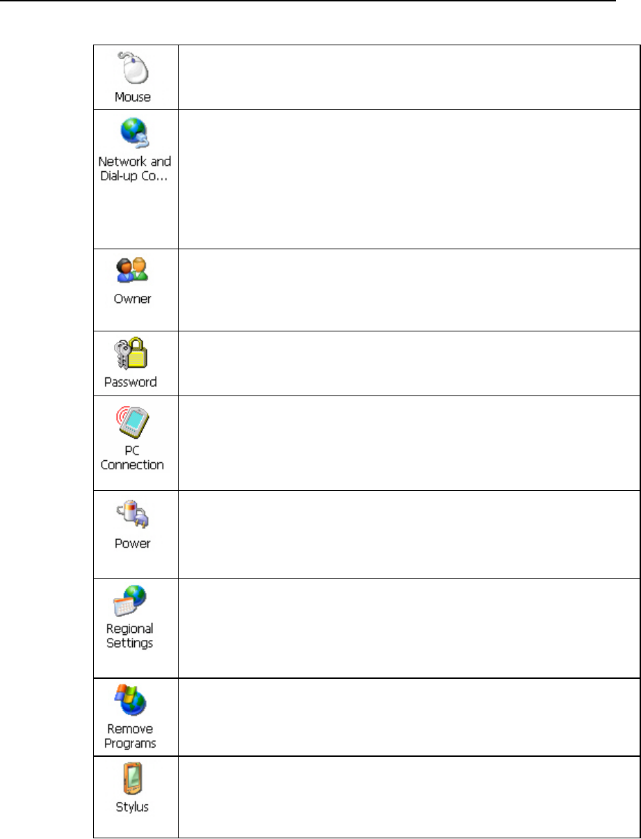
Connect a mouse to the cradle via the USB Host port.
In the [Mouse Properties] dialog box, you may configure and test your double-click
settings.
In the [Network and Dial-up Connections] window, you may configure settings for
the terminal connects to a network directly or through a modem. Alternatively, you
may tap Start > Settings > Network and Dial-up Connections.
USB Connection (via USB client port on the cradle)
AX88772 (via Ethernet port on the cradle)
WLAN (via 802.11b/g)
BTPAN (via Bluetooth)
In the [Owner Properties] dialog box,
Identification/Notes tab: Enter your contact information or notes.
Network ID tab: Enter the user name, password, and domain name used to log on
to the remote network.
In the [Password Properties] dialog box, you may apply password protection to limit
access to the terminal.
In the [PC Connection Properties] dialog box, you may disable the direct connection
between the terminal and a computer.
By default, the terminal is enabled to directly connect to a computer via the cradle’s
USB port. Alternatively, you may tap Start > Settings > Network and Dial-up
Connections and select USB Connection.
In the [Power Properties] dialog box,
Battery tab: You may view the current status of main and backup batteries.
Schemes tab: You may configure the power scheme and switching.
Device Status tab: You may view the devices that are consuming power.
In the [Regional and Language Settings] dialog box,
Region tab: You may customize the appearance and formatting to your
geographic region.
Language tab: By default, it is set to English (United States).
Input tab: By default, it is set to English (United States)-US.
In the [Remove Programs] dialog box, you may remove any program that is installed
earlier.
In the [Stylus Properties] dialog box,
Double-Tap tab: You may configure and test your double-tap settings.
Calibration tab: You may need to re-calibrate the touch screen if it is not
responding properly to your taps.
54 9500CE Terminal Reference Manual
In the [System Properties] dialog box,
General tab: You may view the system information.
Memory tab: You may move the slider and adjust the SDRAM allocation.
Device Name tab: You may enter a name and description for identifying the
terminal.
Copyrights tab: You may view the important statements on copyrights.
In the [Volume & Sounds Properties] dialog box,
Volume tab: You may move the slider and adjust the volume and select to play
sounds for Events, Applications or Notifications.
Sounds tab: You may configure sounds for different Windows events.
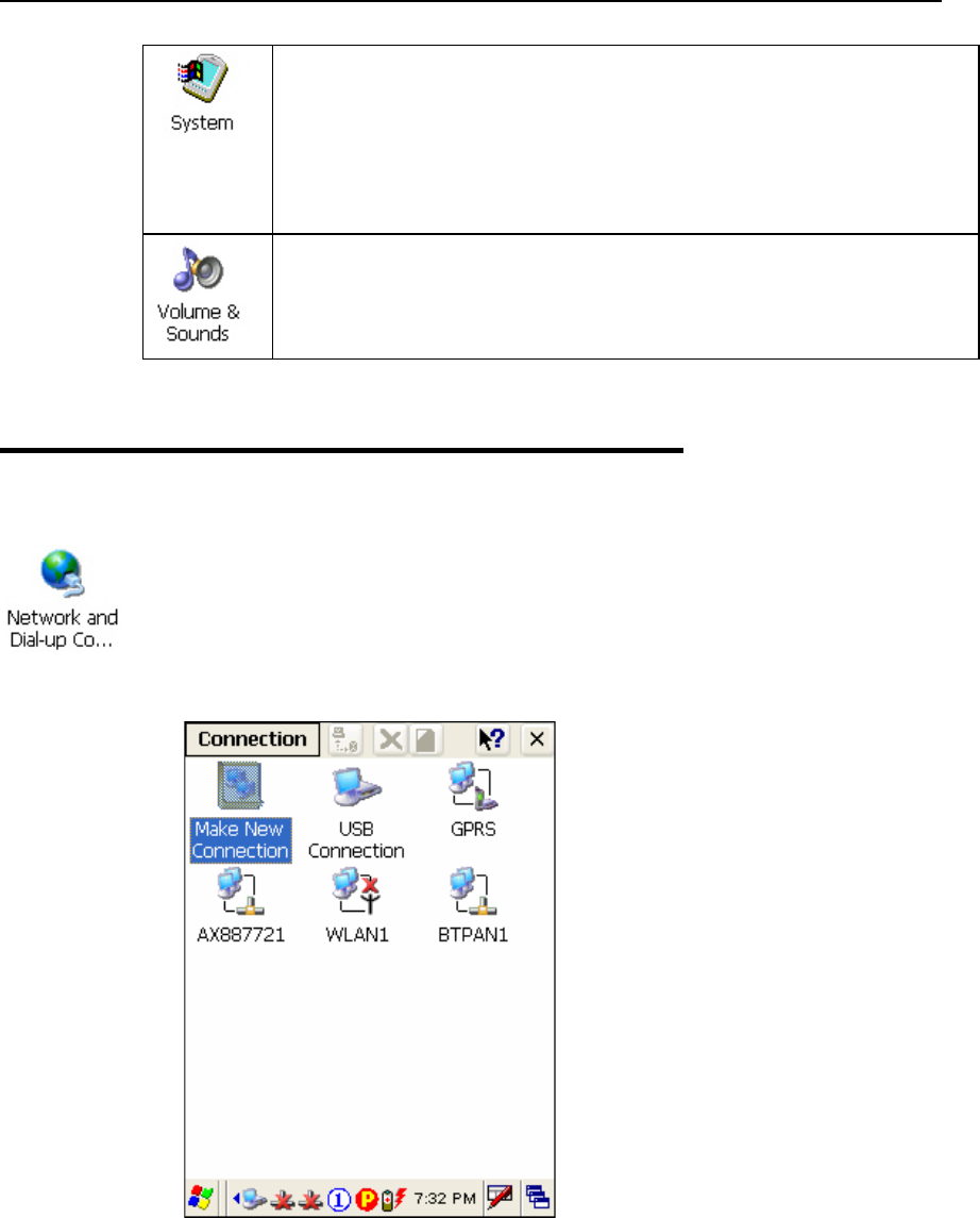
4.2 Connections
There are two ways to access the connections settings:
Go to Start > Settings > Control Panel and double-tap the Network and Dial-up
Connections icon.
Go to Start > Settings > Network and Dial-up Connections.
Chapter 4 ʳʳʳʳʳʳʳʳʳʳʳʳʳʳʳʳʳʳʳʳʳʳʳʳʳʳʳʳʳʳʳʳʳʳʳ 55
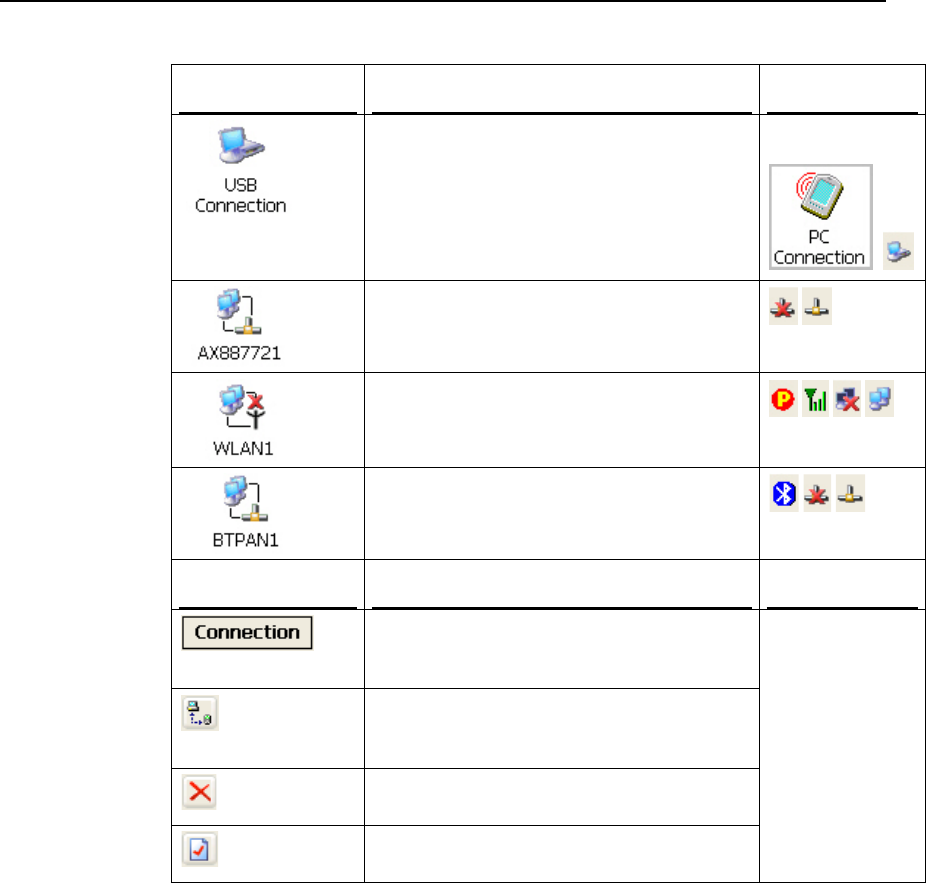
Type of Connections Description See Also
This is a shortcut to USB Connection, and the
selected interface is USB for factory setting.
This connection is reflected in the control panel
for direct PC connection.
Start > Settings >
Control Panel >
/
This is the control of Ethernet module
AX88772, which is enabled by default.
This is the control of 802.11b/g module for
wireless local area networking (WLAN)
connection, which is disabled by default.
This is the control of Bluetooth module for
wireless personal area networking (WPAN)
connection, which is enabled by default.
Toolbar Description See Also
Tap this button to open the Connection menu.
The available options depend on the connection
you select.
Tap this button to toggle on/off the connection
you select. The toggle is used for Enable/Disable
or Connect/Disconnect.
Tap this button to delete the connection you
select.
Tap this button to view the properties of the
connection you select.
Tap and hold the
icon of a desired
connection type.
Then, select from
its associated
menu.
56 9500CE Terminal Reference Manual
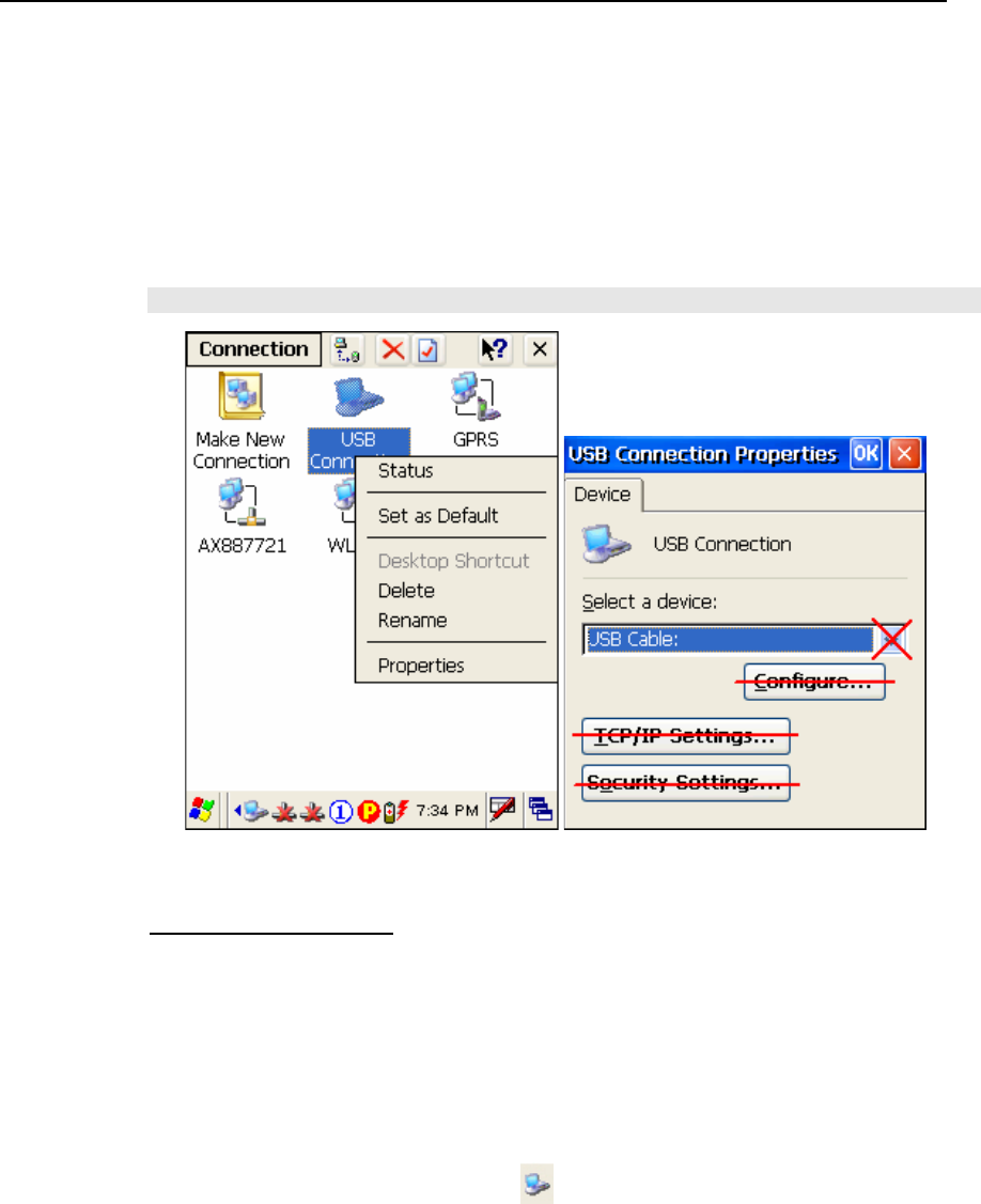
4.2.1 USB Connection
Tap and hold on “USB Connection”.
Most options can be found in the Connection menu on the toolbar as well.
When you select [Set as Default], the USB Connection will become the default
connection used for browsing the Internet.
Note: Please ignore [Properties] as the associated settings will not take effect.
Connect / Disconnect
The USB connection is specifically for performing the ActiveSync operation.
Generally, it will automatically establish the connection and start the ActiveSync
operation when you seat the terminal in the cradle. To stop the ActiveSync
operation, simply remove the terminal.
If you want to stop the ActiveSync operation without removing the terminal from
the cradle, tap and hold on “USB Connection”, and select [Status]. Then, tap
[Disconnect] in the dialog box.
When connected, the status icon will appear on the taskbar.
When disconnected, this icon will disappear.
Chapter 4 57
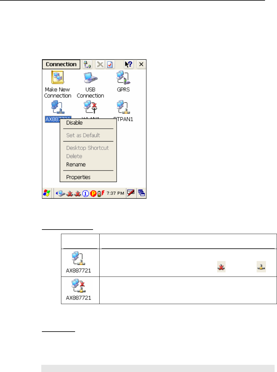
4.2.3 AX88772 (Ethernet)
Tap and hold on “AX887721”.
Enable / Disable
Icons Description
By default, the Ethernet module is enabled.
When a Cat. 5 cable is connected, the status icon will become .
Tap and hold on “AX887721”, and select [Disable]. The status icon will
disappear.
Properties
By default, DHCP is enabled, and therefore, there is no need to configure the IP
settings. If you want to assign a static IP address to the terminal, tap and hold on
“AX887721”, and then select [Properties].
Note: Only change these settings according to your network administrator’s instructions.
58 9500CE Terminal Reference Manual
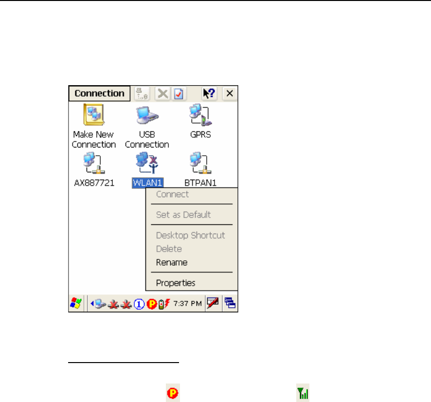
4.2.4 WLAN
Tap and hold on “WLAN1”.
Connect / Disconnect
1. Turn on the power to the 802.11b/g module through the Wireless Power Manager. Its
associated icon on the taskbar will become .
The WLAN1 dialog box appears for establishing a connection.
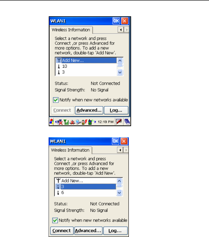
Chapter 4 59
2. Select an access point or Wi-Fi enabled device, and tap the [Connect] button.
For initial connection, the Wireless Properties dialog box will appear first. Tap [OK]
after configuration.
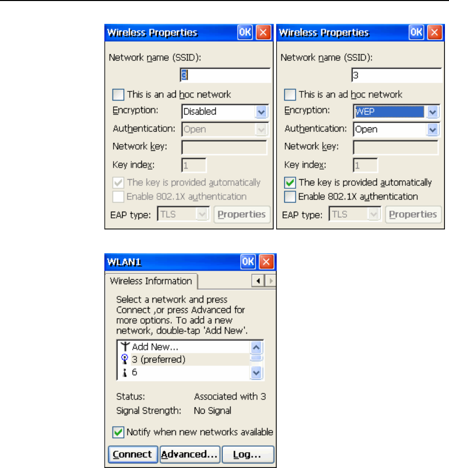
60 9500CE Terminal Reference Manual
3. Wait a few seconds for the terminal to connect to the selected network.
4. If you need to change the network settings, double-tap the selected network. The
Wireless Properties dialog box appears as shown in step 2. Tap [OK] after
configuration.
For more network settings, tap the [Advanced] button on the Wireless Information
tab.
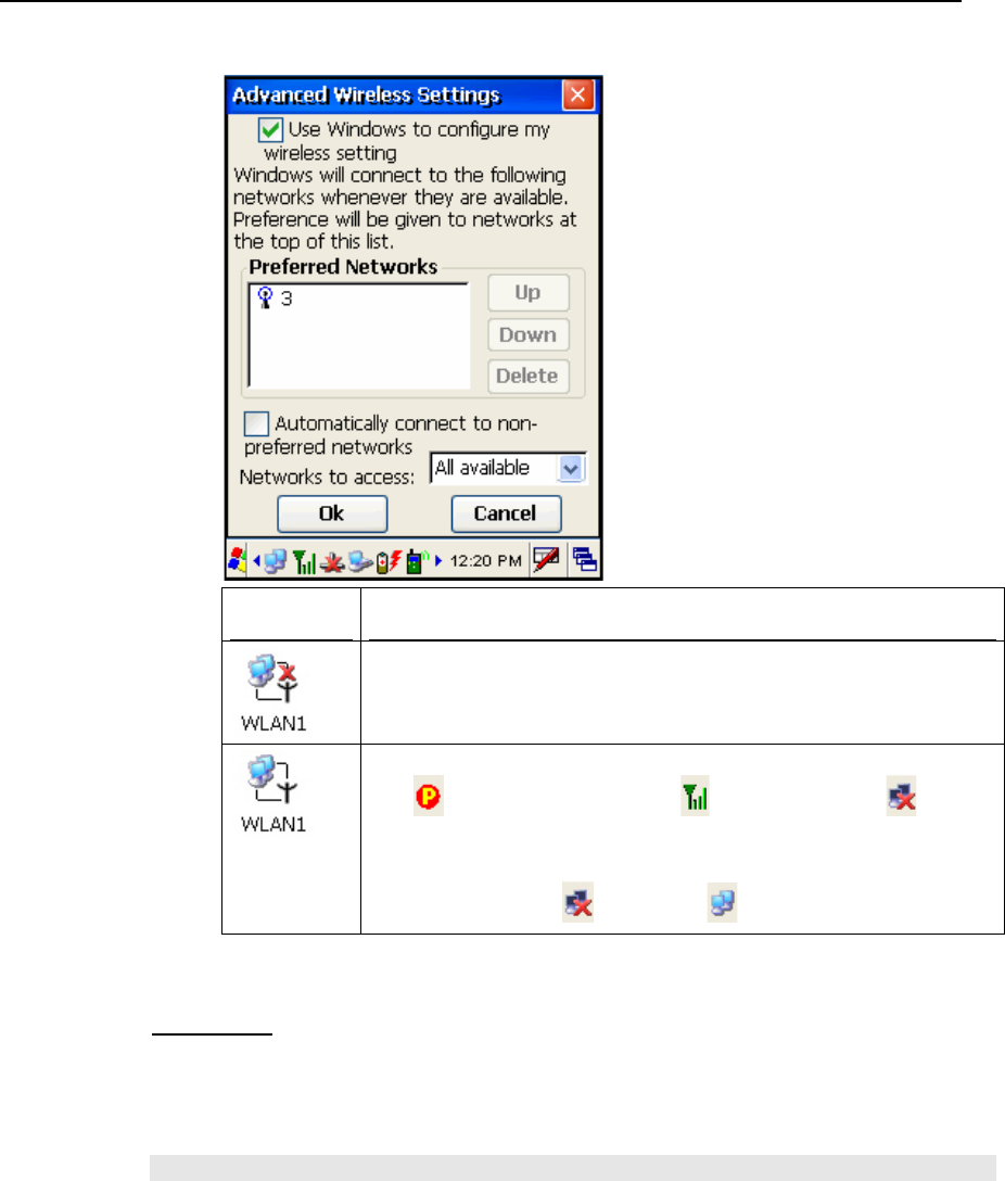
Chapter 4 61
Icons Description
By default, the 802.11b/g module is disabled. No status icon.
Enable the 802.11b/g module through the Wireless Power Manager. The
icon on the taskbar will become , and the status icon will
appear.
When successfully connecting to an access point or other Wi-Fi enabled
device, the status icon will become .
Properties
By default, DHCP is enabled, and therefore, there is no need to configure the IP
settings. If you want to assign a static IP address to the terminal, tap and hold on
“WLAN1”, and then select [Properties].
Note: Only change these settings according to your network administrator’s instructions.
62 9500CE Terminal Reference Manual
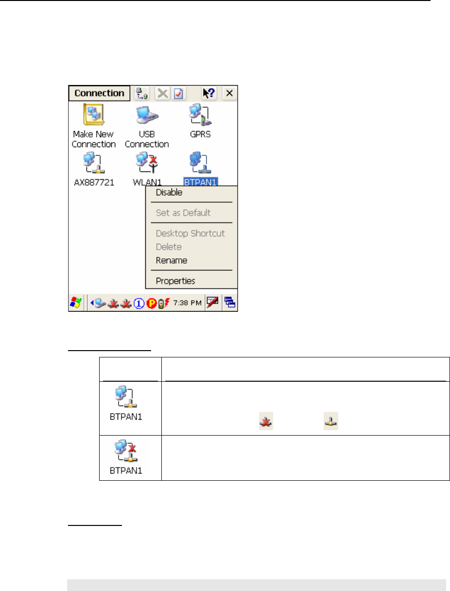
4.2.5 BTPAN
Tap and hold on “BTPAN1”.
Enable / Disable
Icons Description
By default, the Ethernet module is enabled.
When the Bluetooth PAN service is connected through the Bluetooth
Manager, the status icon will become .
Tap and hold on “BTPAN1”, and select [Disable]. The status icon will
disappear.
Properties
By default, DHCP is enabled, and therefore, there is no need to configure the IP
settings. If you want to assign a static IP address to the terminal, tap and hold on
“BTPAN1”, and then select [Properties].
Note: Only change these settings according to your network administrator’s instructions.

63
The 9500CE Terminal terminal provides several utilities and key applications which are
made accessible from the desktop or the taskbar.
Wireless Power Manager lets you determine whether the power is supplied to the
WLAN module, along with its associated driver installed.
Bluetooth Manager lets you configure the Bluetooth settings and use the Bluetooth
services provided on the remote devices.
ReaderCfg lets you manage the barcode or RFID reader.
Inbox lets you send and receive e-mail by connecting to a POP3 or IMAP4 server.
CHAPTER 5
Applications
64 9500CE Terminal Reference Manual
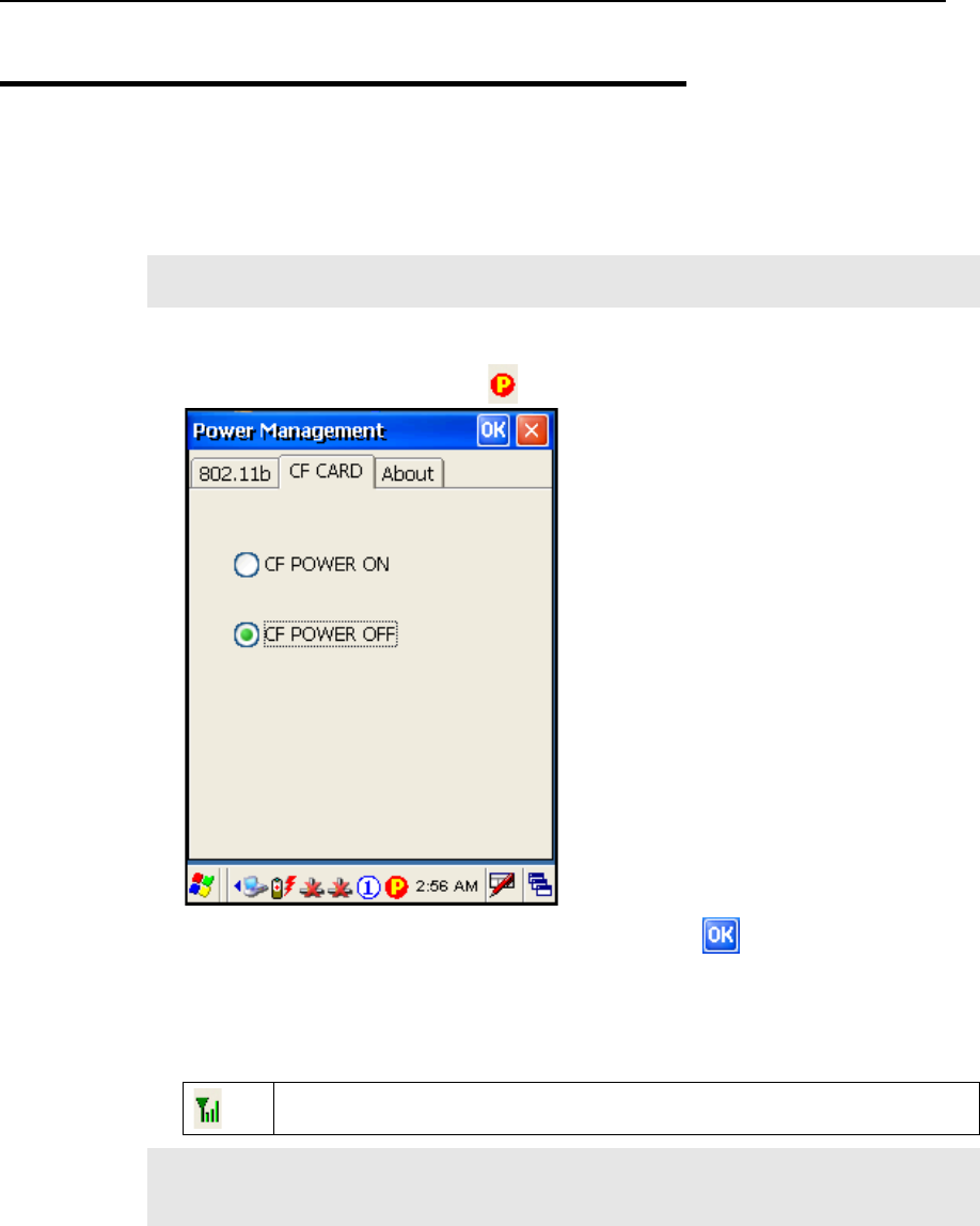
5.1 Wireless Power Manager
Wireless Power Manager is a control panel applet, which allows you to choose and enable
802.11b/g.
Note: Meanwhile, you may enable Bluetooth connectivity through the Bluetooth
Manager.
1. Double-tap the associated icon on the taskbar to run Wireless Power Manager.
2. Select the wireless connectivity you desire, and then tap .
It takes several seconds to turn on the power to the wireless module and install the
driver. When 802.11b/g are enabled on battery power, the main battery charge will drop
down substantially.
Double-tap any of the following icons to access power management.
The icon indicates that 802.11b/g Power is turned on.
Note: You may need to turn off the wireless power or simply stop the wireless signals at
times, in order to conserve battery power, or in situations where the use of radio is
prohibited, such as on airplanes, in hospitals, etc.
Chapter 5 65
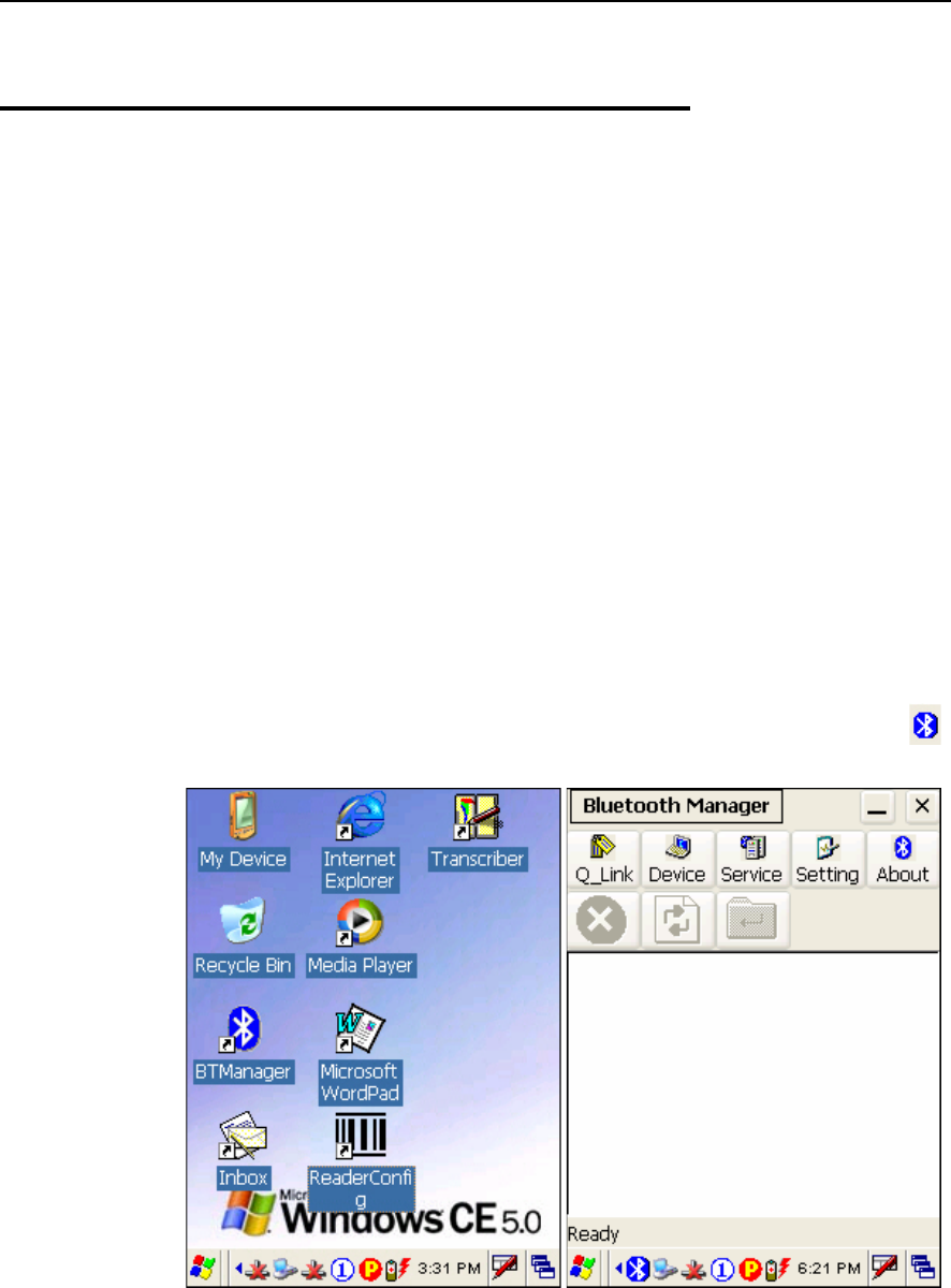
5.2 Bluetooth Manager
Bluetooth Manager is a utility that helps you access and manage the available Bluetooth
services efficiently.
The supported Bluetooth profiles are:
Serial Port Profile (SPP)
Object Push Profile (OPP)
File Transfer Profile (FTP)
Dial-Up Networking Profile (DUN)
PAN Service Profile (PAN)
Human Interface Device Profile (HID)
5.2.1 Start Bluetooth Services
1. Double-tap the Bluetooth Manager shortcut on the desktop (left below).
2. It takes several seconds to enable the Bluetooth services. The associated icon will
appear on the taskbar. (right below)
66 9500CE Terminal Reference Manual
Note: To start Bluetooth PAN service, go to Start > Settings > Network and Dial-up
Connections.
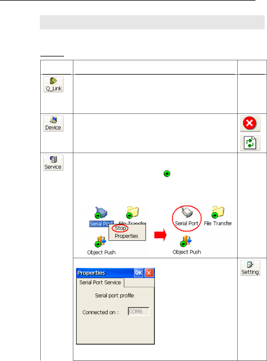
Toolbar
Buttons Description See Also
Tap this button to view shortcuts to preferred Bluetooth services, which
may be provided on different Bluetooth devices. Then tap a desired
Bluetooth service to establish a quick link.
You will have to make a connection and created a shortcut to a specific
Bluetooth service first.
Tap this button to view the Bluetooth devices discovered during this
session.
If you tap the button for the first time, it will start the inquiry
process to discover nearby Bluetooth devices.
Tap this button to view the Bluetooth services provided.
By default, these services are all available, and therefore,
displayed along with a plug icon “ ”.
To view properties of a service, tap and hold it. Then select
[Properties].
To disable a service, tap and hold it. Then select [Stop].
Serial Port
Properties
If “Auto Server COM Port” is enabled –
If “Auto Server COM Port” is disabled, you can select a COM port by
following these steps:
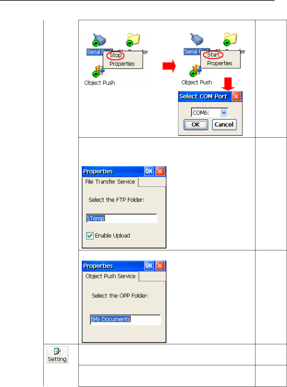
Chapter 5 67
File
Transfer
Properties
You can change the FTP folder.
By default, uploading files to the terminal is allowed. You can
cancel the check box to prohibit uploading.
Object Push
Properties
You can change the Bluetooth exchange folder.
Tap this button to view the Bluetooth properties.
General tab It displays device name, MAC address, as well as the device type.
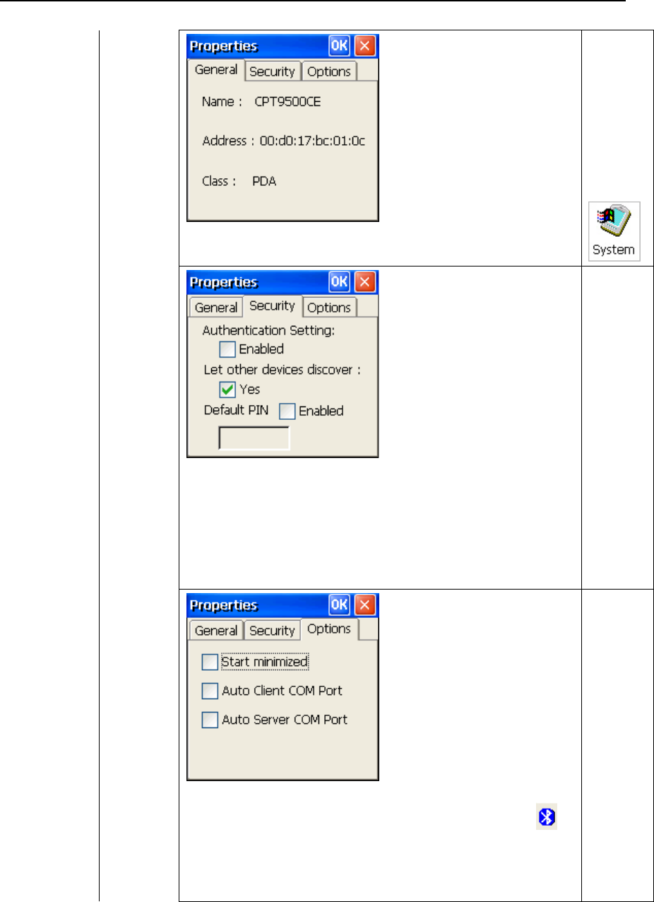
68 9500CE Terminal Reference Manual
If you wish to change the device name of the terminal, go to Start >
Settings > Control Panel and select System.
Security tab
Authentication Setting: It is disabled by default. When enabled,
PIN code is required.
Discoverability: It is set discoverable by default. If you do not wish
to provide Bluetooth services to other remote devices, cancel the
check box.
Default PIN: It is disabled by default. You may set a link key to
skip the PIN code input.
Options tab
Start minimized: When selected, once you run the Bluetooth
Manager program, its window will be minimized to an icon on
the taskbar, which serves as a toggle to open or close the Bluetooth
Manager window. It works the same as the “Minimized” button
below.
Auto Client COM Port: When enabled, the default COM port for
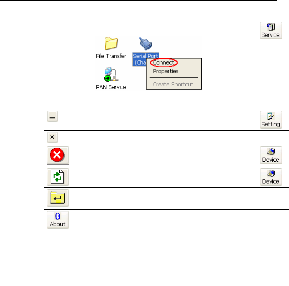
Chapter 5 ʳʳʳʳʳʳʳʳʳʳʳʳʳʳʳʳʳʳʳʳʳʳʳʳʳʳʳʳʳʳʳʳʳʳʳ 69
remote Serial Port service will be assigned automatically. When
disabled, you can select a COM port by selecting [Connect]:
Auto Server COM Port: When enabled, the default COM port for
local Serial Port service will be assigned automatically.
Tap this button to minimize the Bluetooth Manager window.
Tap this button to exit the Bluetooth Manager.
Tap this button to stop inquiring.
Tap this button to refresh the deice list.
When using the File Transfer service on a remote device, you can tap
this button to move up one level if a subfolder exists.
Tap this button to view the Bluetooth profiles supported:
SPP for Serial Port Profile
OPP for Object Push Profile
FTP for File Transfer Profile
DUN for Dial-Up Networking Profile (supports Client only)
Note that the terminal also supports the following profiles:
PAN Service Profile
Human Interface Device (HID) Profile
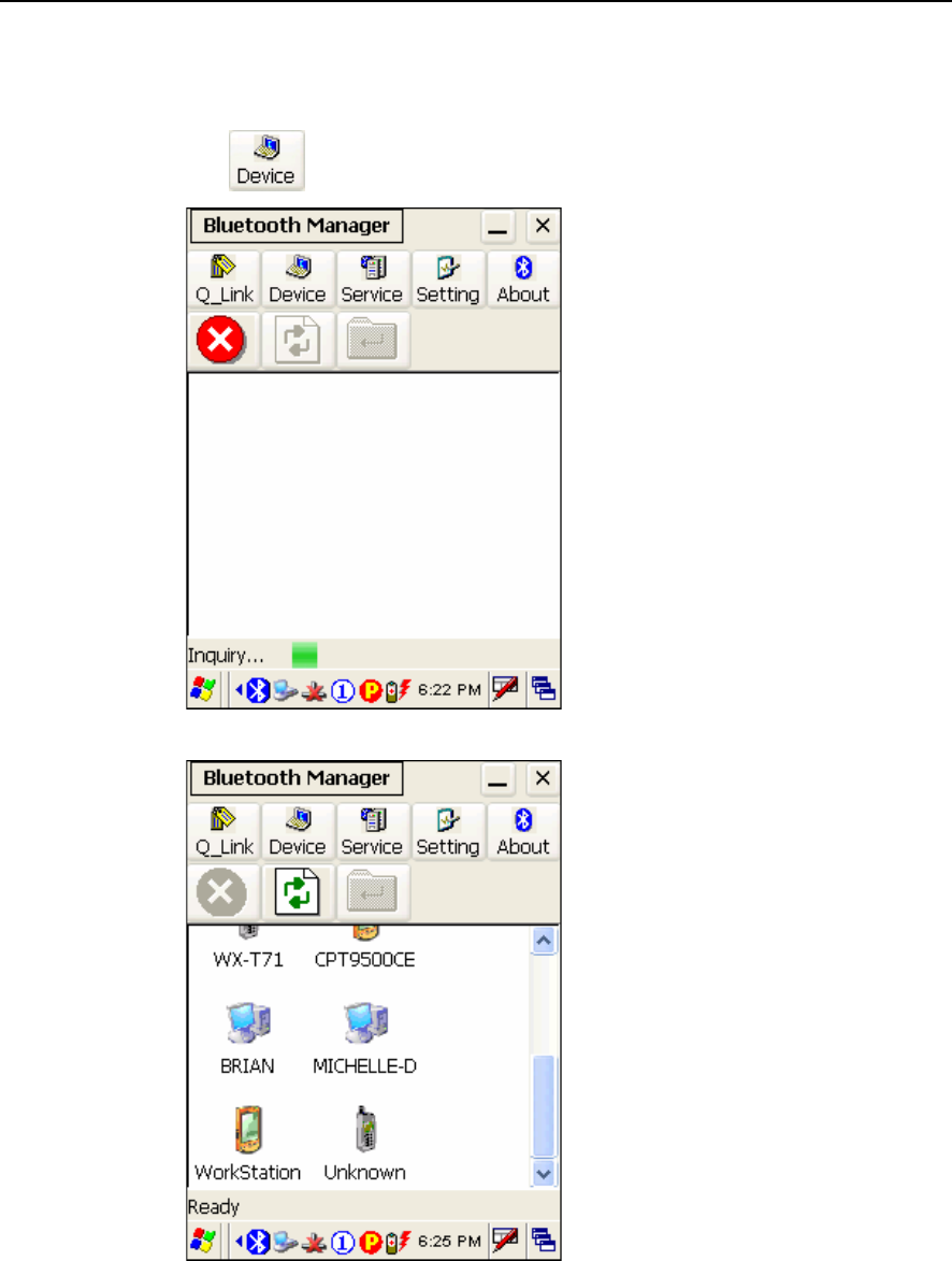
70 9500CE Terminal Reference Manual
5.2.2 Inquiry
1. Tap to discover nearby Bluetooth devices.
2. It will list the discovered devices.
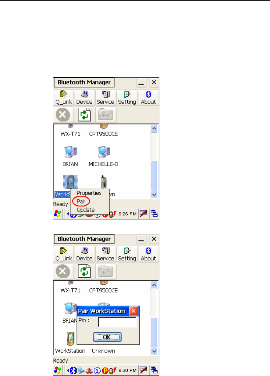
Chapter 5 71
5.2.3 Pair
When authentication is enabled on the target device, you will have to pair with it before
starting a connection.
1. From the device list, tap and hold on the desired device and tap [Pair].
2. Enter the PIN code that is specified on the remote device.
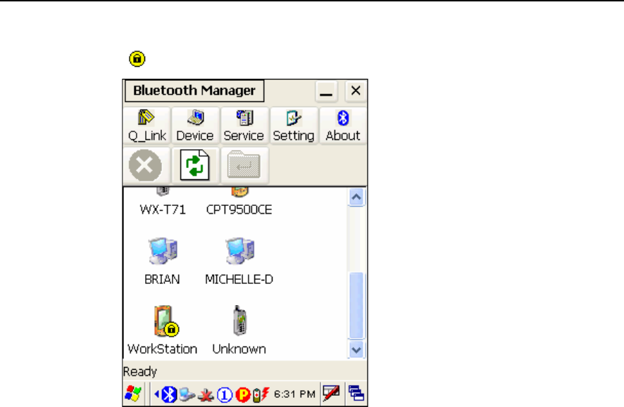
72 9500CE Terminal Reference Manual
3. Once paired successfully, the paired device will be displayed along with a lock icon
“”.
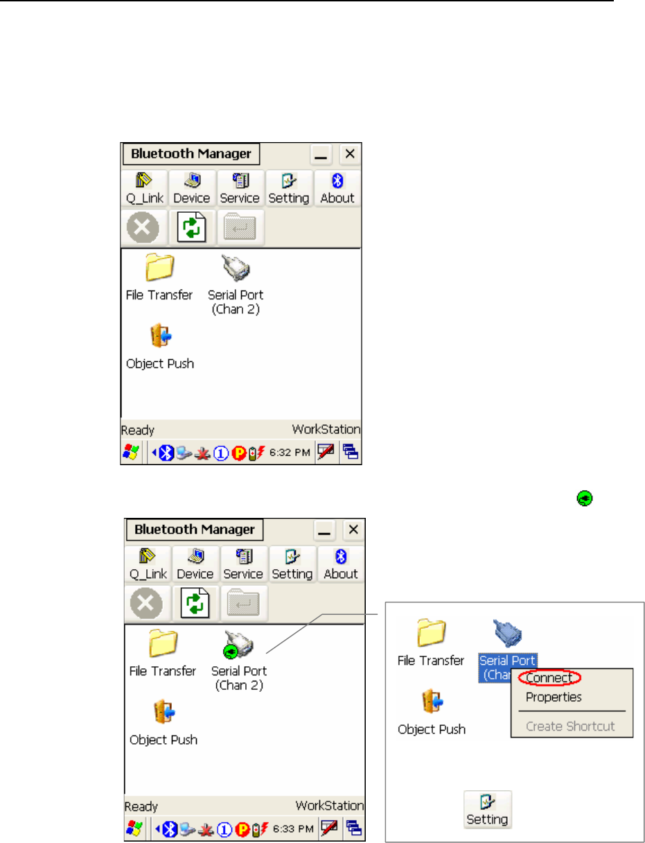
Chapter 5 73
5.2.4 Connect
1. From the device list above, double-tap a device to find out the available Bluetooth
services.
2. Tap and hold a desired Bluetooth service, e.g. Serial Port Service, to establish a
connection. The connected service will be displayed along with a plug icon “ ”.
Tap [Connect] and then select a COM
port when “Auto Client COM Port” is
disabled in .
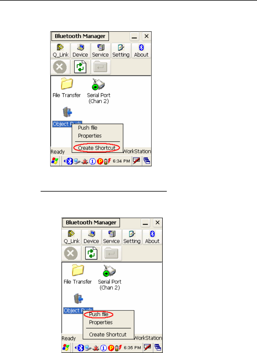
74 9500CE Terminal Reference Manual
3. If you wish to add a service to the Q_Link list for establishing a quick connection in the
future, tap and hold it, and then select [Create Shortcut].
Steps to access the Object Push service:
1. Tap and hold the Object Push service.
2. Select [Push file] to send a file or PIM item, e.g. a business card.
3. Choose the file you wish to send.
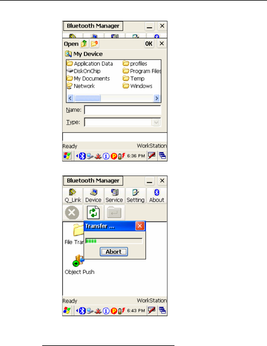
Chapter 5 75
4. The terminal will start transferring the file.
Steps to access the File Transfer service:
1. Tap and hold the File Transfer service.
2. Select [Connect] (and assign COM port if necessary).
3. Tap and hold on anywhere blank. Then, select [Add file].
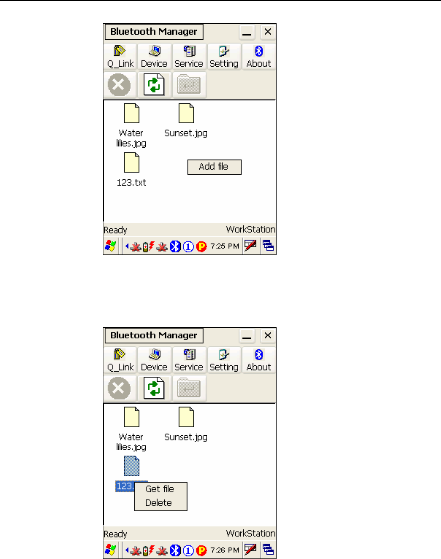
76 9500CE Terminal Reference Manual
4. Choose the file you wish to upload to the remote device.
5. The terminal will start transferring the file.
6. To download a file from the remote device, tap and hold on a desired file. Then,
select [Get file].
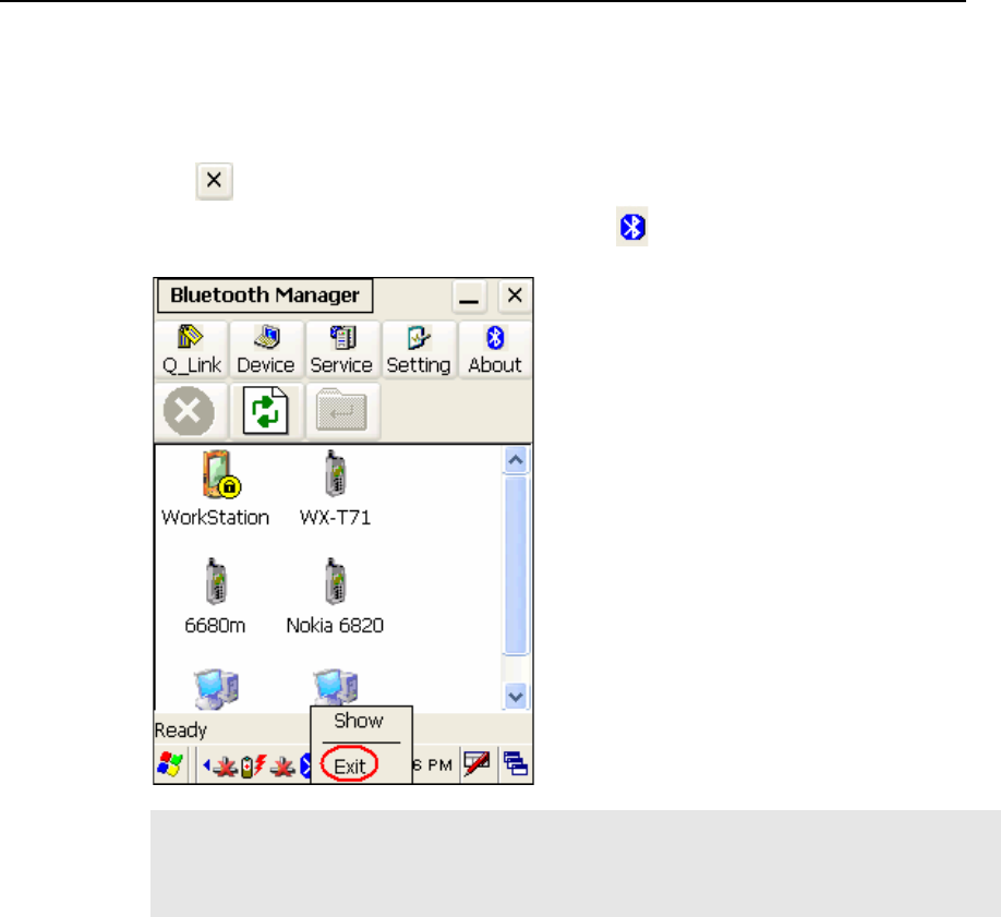
Chapter 5 77
5.2.5 Stop Bluetooth Services
Tap on the toolbar of the Bluetooth window to stop all Bluetooth connections. When
the Bluetooth window is minimized, tap and hold on the taskbar, and then select [Exit].
Note: You may need to stop using the Bluetooth services, in order to conserve battery
power, or in situations where the use of radio is prohibited, such as on airplanes, in
hospitals, etc. To stop Bluetooth PAN service, go to Start > Settings > Network and
Dial-up Connections.
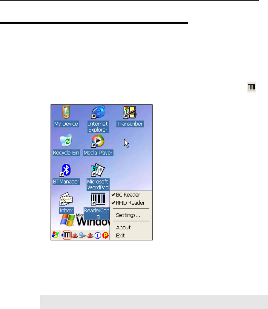
78 9500CE Terminal Reference Manual
5.3 ReaderConfig
ReaderConfig is the control applet and tool to manage the barcode and RFID readers
integrated on the terminal.
1. Double-tap the ReaderConfig shortcut on the desktop. The associated icon will
appear on the taskbar.
2. Tap and hold on the icon to access the menu that allows you to choose and enable one or
both of the readers. There will be a check mark in front of the reader if it is enabled.
BC Reader: 1D or 2D
RFID Reader
3. To meet your application requirements, proceed to configure associated reader settings.
Note: The program ReaderCfg will automatically detect the reader module(s) that is
currently installed in the terminal.
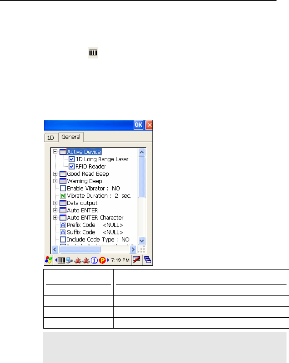
Chapter 5 79
5.3.1 Configure Reader Settings
Tap and hold on , and then select BC Reader or RFID Reader. If it is ticked, the reader is
enabled. Otherwise, it is disabled.
The default reader is BC Reader for reading barcodes. If the RFID Reader is installed, the
option will be available. If you need to change the factory settings, select [Settings].
The reader configurations depend on the barcode reader installed. To identify the barcode
reader, check inside the “Active Device” setting.
Active Device Description
1D Reader The scan engine is CCD or Laser.
1D Long Range Laser The scan engine is Long Range Laser or Extra Long Range Laser.
2D Reader The scan engine can read linear and 2D barcodes.
RFID The reader can read RFID tags.
Note: (1) For barcode settings, click the 1D or 2D tab that is next to the General tab.
(2) For RFID settings, click the General tab and roll to the bottom of the list.
(3) If you wish to reload the default settings, delete the ReaderCfg.ini file in
DiskOnChip.

80 9500CE Terminal Reference Manual
5.3.2 1D Reader - CCD / Laser
General tab
Settings Default
Active Device The scan engine can be identified and toggled. Only
one scan engine can be disabled at a time.
1D Reader
RFID
Barcode Reader
is always enabled
if exists.
Good Read Beep Mute, or Sound 1~9 Sound 2
Warning Beep Mute, or Sound 1~9 Sound 9
Enable Vibrator YES or NO NO (Disabled)
Vibrator Duration 1~30 (sec.) *Vibrator must be enabled. 2 seconds
Data Output There are three options for data output after decoding:
Keyboard Emulation
- Data is emulated as typed text and sent to the
active Window.
- Simply run your application or Pocket PC
built-in program, such as Pocket Excel, to
start with data collection.
Windows Message
- Data is encapsulated in a Windows message
(WM_COPYDATA).
- Retrieve the WM_COPYDATA message in
your application.
- The decoded data is passed to your application
through the lParam parameter.
Windows Event
- Whenever the reader reads a barcode, a
Windows event object named “DecodeEvent”
will be signaled and the data will be stored in
the Windows message queue.
- Need to create an event object named
“DecodeEvent” in your application so that the
ReaderCfg utility can signal your application
using this event object.
- Call Windows API (ReadMsgQueue) in your
application to retrieve the decoded data.
*Sample programs are provided for Windows Message
& Event programming. For details, please contact
CipherLab technical support team.
Keyboard
Emulation

Chapter 5 ʳʳʳʳʳʳʳʳʳʳʳʳʳʳʳʳʳʳʳʳʳʳʳʳʳʳʳʳʳʳʳʳʳʳʳʳʳʳ 81
Note: For the use of a different program rather than ReaderCfg, a dynamic-link library
(DLL) file is provided.
Auto ENTER This function can spare you the trouble of pressing the
[Enter] key on the terminal to confirm each scan. It will
automatically add an ENTER character in front or to
the end of one scan.
No
Scan + ENTER (time-saving)
ENTER + Scan (efficient for continuous scanning)
Scan + ENTER
Auto ENTER
Character
*Auto ENTER must be enabled.
None
Carriage Return
Tab
Space
Comma
Semicolon
Carriage Return
Prefix Code 0~10 characters NULL
Suffix Code 0~10 characters NULL
Include Cody Type YES or NO NO (Disabled)
Include Cody Length YES or NO NO (Disabled)
Scan Mode Refer to Appendix I Comparison of Scan Modes.
Auto Off
Continuous
Auto Power Off
Alternate
Momentary
Repeat
Laser
Test
Aiming
Laser mode
Barcode Decode
Timeout
1~255 (sec.) 3 seconds
Barcode Read
Redundancy
Select a desired level of reading (decoding) security.
Comprise some speed for getting more security when
necessary. For example, if “None” is selected, it only
requires one successful decoding to make the reading
valid. If “Three times” is selected, it needs to
successfully decode three more times to make the
reading valid.
None
None

82 9500CE Terminal Reference Manual
One time
Two times
Three times
Negative Barcode Normally, barcodes are printed with the color of the
bars darker than that of the spaces. For negative
barcodes, they are printed oppositely just like negative
films. That is, the spaces of the negative barcodes are
printed with the color darker than that of the bars.
YES or NO
NO (Disabled)
RFID Settings will be displayed if the RFID reader is installed!
Check reader status
when start session
When running the program, it will take a few seconds
to check status of the reader, barcode reader or RFID
reader, before starting the session.
YES or NO
YES (Enabled)

Chapter 5 83
1D tab: CCD / Laser
Code 39 Supported on CCD / Laser Default
Enabled or Disabled Enabled
Transmit Start / Stop When enabled, the start / stop characters will be
included in the data being transmitted.
OFF (Disabled)
Verify Checksum When enabled, the checksum verification will be
performed in decoding.
If the checksum is incorrect, data will be rejected.
OFF (Disabled)
Transmit Checksum The checksum character is included in the data being
transmitted.
ON (Enabled)
Code 39 Full ASCII When enabled, Code 39 Full ASCII will be supported
instead. All the alphanumeric and special characters are
included.
OFF (Disabled)
Italian Pharmacode Supported on CCD / Laser Default
Enabled or Disabled Disabled
Transmit Start / Stop *Share the setting of Code 39.
Transmit Checksum The checksum character is included in the data being
transmitted.
ON (Enabled)
French Pharmacode Supported on CCD / Laser Default
Enabled or Disabled Disabled
Transmit Start / Stop *Share the setting of Code 39.
Transmit Checksum The checksum character is included in the data being
transmitted.
ON (Enabled)
Industrial 25 Supported on CCD / Laser Default
Enabled or Disabled Enabled
Start / Stop
Character
The start / stop character of the selected barcode is
included in the data being transmitted.
Industrial 25
Interleaved 25
Matrix 25
Industrial 25
Verify Checksum When enabled, the checksum verification will be
performed in decoding.
OFF (Disabled)

84 9500CE Terminal Reference Manual
If the checksum is incorrect, data will be rejected.
Transmit Checksum The checksum character is included in the data being
transmitted.
ON (Enabled)
Length Qualification The weak structure of some barcodes may cause a
“short scan” error. This setting is used to prevent such
an error by qualifying the allowable barcode length to
ensure the correct barcode is read.
Fixed Length (up to 2 lengths can be specified)
Max / Min Length
By default, the terminal will only accepts those
barcodes with lengths that fall between the maximum
and minimum lengths; otherwise, data will be rejected.
Max / Min
Length
Maximum Length 0~127 characters 127
Minimum Length 0~127 characters 1
Interleaved 25 Supported on CCD / Laser Default
Enabled or Disabled Enabled
Start / Stop
Character
The start / stop character of the selected barcode is
included in the data being transmitted.
Industrial 25
Interleaved 25
Matrix 25
Interleaved 25
Verify Checksum When enabled, the checksum verification will be
performed in decoding.
If the checksum is incorrect, data will be rejected.
OFF (Disabled)
Transmit Checksum The checksum character is included in the data being
transmitted.
ON (Enabled)
Length Qualification Refer to Industrial 25 above.
Fixed Length
Max / Min Length
Max / Min
Length
Maximum Length 0~127 characters 126
Minimum Length 0~127 characters 1
Matrix 25 Supported on CCD / Laser Default
Enabled or Disabled Disabled
Start / Stop
Character
The start / stop character of the selected barcode is
included in the data being transmitted.
Industrial 25
Interleaved 25
Matrix 25

Chapter 5 85
Matrix 25
Verify Checksum When enabled, the checksum verification will be
performed in decoding.
If the checksum is incorrect, data will be rejected.
OFF (Disabled)
Transmit Checksum The checksum character is included in the data being
transmitted.
ON (Enabled)
Length Qualification Refer to Industrial 25 above.
Fixed Length
Max / Min Length
Max / Min
Length
Maximum Length 0~127 characters 127
Minimum Length 0~127 characters 1
Codabar Supported on CCD / Laser Default
Enabled or Disabled Enabled
Start / Stop
Character
When enabled, the selected start / stop characters will
be included in the data being transmitted.
None
abcd / abcd
abcd / tn*e
ABCD / ABCD
ABCD / TN*E
None
MSI Supported on CCD / Laser Default
Enabled or Disabled Disabled
Verify Checksum Using the selected calculation method, the checksum
verification is performed in decoding.
If the checksum is incorrect, data will be rejected.
Single Modulo 10
Double Modulo 10
Modulo 11 & 10
Single Modulo
10
Transmit Checksum Based on the selected conditions, the checksum
characters are included in the data being transmitted.
Last digit not transmitted
Transmitted
Last 2 digits not transmitted
Transmitted
Length Qualification Refer to Industrial 25 above.
Fixed Length
Max / Min
Length

86 9500CE Terminal Reference Manual
Max / Min Length
Maximum Length 0~127 characters 127
Minimum Length 0~127 characters 0
Plessey Supported on CCD / Laser Default
Enabled or Disabled Disabled
Convert to UK
Plessey
When enabled, each occurrence of the character “A”
will be converted to “X”.
OFF (Disabled)
Transmit Checksum The checksum characters (2 digits) are included in the
data being transmitted.
ON (Enabled)
UPC-E Supported on CCD / Laser Default
Enabled or Disabled Enabled
Convert to UPC-A When enabled, the UPC-E reading will be expanded
into UPC-A. It will then be processed according to the
settings of UPC-A.
OFF (Disabled)
Transmit System
Number
When enabled, the system number will be included in
the data being transmitted.
OFF (Disabled)
Transmit Checksum The checksum character is included in the data being
transmitted.
ON (Enabled)
Transmit Addon 2 When enabled, UPC-E Addon 2 can be decoded too. OFF (Disabled)
Transmit Addon 5 When enabled, UPC-E Addon 5 can be decoded too. OFF (Disabled)
EAN-8 Supported on CCD / Laser Default
Enabled or Disabled Enabled
Convert to EAN-13 When enabled, the EAN-8 reading will be expanded
into EAN-13. It will then be processed according to the
settings of EAN-13.
OFF (Disabled)
Transmit Checksum The checksum character is included in the data being
transmitted.
ON (Enabled)
Transmit Addon 2 When enabled, EAN-8 Addon 2 can be decoded too. OFF (Disabled)
Transmit Addon 5 When enabled, EAN-8 Addon 5 can be decoded too. OFF (Disabled)
EAN-13 Supported on CCD / Laser Default
Enabled or Disabled Enabled
Convert to ISBN When enabled, the EAN-13 reading that starts with 978 OFF (Disabled)

Chapter 5 87
and 979 will be converted to ISBN.
Convert to ISSN When enabled, the EAN-13 reading that starts with 977
will be converted to ISSN.
OFF (Disabled)
Transmit Checksum The checksum character is included in the data being
transmitted.
ON (Enabled)
Transmit Addon 2 When enabled, EAN-13 Addon 2 can be decoded too. OFF (Disabled)
Transmit Addon 5 When enabled, EAN-13 Addon 5 can be decoded too. OFF (Disabled)
UPC-A Supported on CCD / Laser Default
*Share the setting of EAN-13. Enabled
Convert to EAN-13 The UPC-A reading will be expanded into EAN-13. It
will then be processed according to the settings of
EAN-13.
ON (Enabled)
Transmit System
Number
The system number is included in the data being
transmitted.
ON (Enabled)
Transmit Checksum The checksum character is included in the data being
transmitted.
ON (Enabled)
Transmit Addon 2 Share the setting of EAN-13 OFF (Disabled)
Transmit Addon 5 Share the setting of EAN-13 OFF (Disabled)
Telepen Supported on CCD / Laser Default
Enabled or Disabled Disabled
Telepen Type Telepen Numeric is supported by default.
Select AIM (Full ASCII) so that Telepen Full
ASCII is supported. All the alphanumeric and
special characters are included.
Original
(Numeric)
RSS-14 Supported on CCD / Laser Default
Enabled or Disabled Disabled
Transmit Checksum The checksum character is included in the data being
transmitted.
ON (Enabled)
Transmit Application
ID
The Application ID is included in the data being
transmitted.
ON (Enabled)
Transmit Code ID The Code ID (default to “]e0”) is included in the data
being transmitted.
ON (Enabled)

88 9500CE Terminal Reference Manual
RSS Limited Supported on CCD / Laser Default
Enabled or Disabled Disabled
Transmit Checksum The checksum character is included in the data being
transmitted.
ON (Enabled)
Transmit Application
ID
The Application ID is included in the data being
transmitted.
ON (Enabled)
Transmit Code ID The Code ID (default to “]e0”) is included in the data
being transmitted.
ON (Enabled)
RSS Expanded Supported on CCD / Laser Default
Enabled or Disabled Disabled
Transmit Code ID The Code ID (default to “]e0”) is included in the data
being transmitted.
ON (Enabled)
Code 93 Supported on CCD / Laser Default
Enabled or Disabled Enabled
Code 128 Supported on CCD / Laser Default
Enabled or Disabled Enabled
EAN-128 Supported on CCD / Laser Default
Share the setting of Code 128 Enabled
Transmit Code ID When enabled, the Code ID (default to “]C1”) is
included in the data being transmitted.
OFF (Disabled)

Chapter 5 89
5.3.3 1D Reader - (Extra) Long Range Laser
General tab
Settings Default
Active Device The scan engine can be identified and toggled. Only
one scan engine can be disabled at a time.
1D (Extra) Long Range Laser
RFID
Barcode Reader
is always enabled
if exists.
Good Read Beep Mute, or Sound 1~9 Sound 2
Warning Beep Mute, or Sound 1~9 Sound 9
Enable Vibrator YES or NO NO (Disabled)
Vibrator Duration 1~30 (sec.) *Vibrator must be enabled. 2 seconds
Data Output There are three options for data output after decoding:
Keyboard Emulation
- Data is emulated as typed text and sent to the
active Window.
- Simply run your application or Pocket PC
built-in program, such as Pocket Excel, to
start with data collection.
Windows Message
- Data is encapsulated in a Windows message
(WM_COPYDATA).
- Retrieve the WM_COPYDATA message in
your application.
- The decoded data is passed to your application
through the lParam parameter.
Windows Event
- Whenever the reader reads a barcode, a
Windows event object named “DecodeEvent”
will be signaled and the data will be stored in
the Windows message queue.
- Need to create an event object named
“DecodeEvent” in your application so that the
ReaderCfg utility can signal your application
using this event object.
- Call Windows API (ReadMsgQueue) in your
application to retrieve the decoded data.
*Sample programs are provided for Windows Message
& Event programming. For details, please contact
CipherLab technical support team.
Keyboard
Emulation

90 9500CE Terminal Reference Manual
Note: For the use of a different program rather than ReaderCfg, a dynamic-link library
(DLL) file is provided.
Auto ENTER This function can spare you the trouble of pressing the
[Enter] key on the terminal to confirm each scan. It will
automatically add an ENTER character in front or to
the end of one scan.
No
Scan + ENTER (time-saving)
ENTER + Scan (efficient for continuous scanning)
Scan + ENTER
Auto ENTER
Character
*Auto ENTER must be enabled.
None
Carriage Return
Tab
Space
Comma
Semicolon
Carriage Return
Prefix Code 0~10 characters NULL
Suffix Code 0~10 characters NULL
Include Cody Type YES or NO NO (Disabled)
Include Cody Length YES or NO NO (Disabled)
Barcode Decode
Timeout
1~99 (0.1 sec.) 3.0 seconds
Timeout When
Decode Same
Barcode
0~99 (0.1 sec.) 1.0 seconds
AIM Duration 0~99 (0.1 sec.) 0.0 seconds
RFID Settings will be displayed if the RFID reader is installed!
Check reader status
when start session
When running the program, it will take a few seconds
to check status of the reader, barcode reader or RFID
reader, before starting the session.
YES or NO
YES (Enabled)

Chapter 5 91
1D tab: (Extra) Long Range Laser
UPC / EAN Supported on (Extra) Long Range Laser Default
Enable UPC-A YES or NO YES (Enabled)
Enable UPC-E0 YES or NO YES (Enabled)
Enable UPC-E1 YES or NO NO (Disabled)
Enable EAN-8 YES or NO YES (Enabled)
Enable EAN-13 YES or NO YES (Enabled)
Enable Bookland
EAN
YES or NO
*EAN-13 must be enabled!
NO (Disabled)
Decode
Supplementary
Digits (Addon 2 & 5)
When enabled, Addon 2 and Addon 5 of UPC /EAN
families can be decoded too.
Ignore Supplementals
Only with Supplementals (Decode barcodes with
Addons only.)
Enable Supplementals (Decode barcodes with or
without Addons.)
Ignore
Supplementals
(Disabled)
Supplementary
Redundancy
With “Enable Supplementals” is selected, it will
autodiscriminate barcodes with or without
supplementals.
Select a desired level of reading (decoding) security.
Comprise some speed for getting more security when
necessary. By default, it requires ten more successful
decoding to make the reading of supplementals
(Addons) valid.
1~255 (decode times)
10 times
Transmit UPC-A
Check Digit
YES or NO YES (Enabled)
Transmit UPC-E0
Check Digit
YES or NO YES (Enabled)
Transmit UPC-E1
Check Digit
YES or NO YES (Enabled)
UPC-A Preamble By default, the selected UPC-A preamble is included in
the data being transmitted.
No Preamble
System Character
System Character & Country Code
System
Character
UPC-E0 Preamble By default, the selected UPC-E0 preamble is included
in the data being transmitted.
System
Character
UPC-E1 Preamble By default, the selected UPC-E1 preamble is included
in the data being transmitted.
System
Character

92 9500CE Terminal Reference Manual
Convert UPC-E0 to
UPC-A
When enabled, the UPC-E0 reading will be expanded
into UPC-A. It will then be processed according to the
settings of UPC-A.
NO (Disabled)
Convert UPC-E1 to
UPC-A
When enabled, the UPC-E1 reading will be expanded
into UPC-A. It will then be processed according to the
settings of UPC-A.
NO (Disabled)
Convert EAN-8 to
EAN-13
When enabled, the EAN-8 reading will be expanded
into EAN-13. It will then be processed according to the
settings of EAN-13.
NO (Disabled)
UCC Coupon
Extended Code
When enabled, it will decode UPC-A barcodes starting
with digit “5”, EAN-13 barcodes starting with digit
“99”, and UPC-A/EAN-128 coupon codes.
*UPC-A, EAN-13, and EAN-128 must be enabled!
**Use “Supplemental Redundancy” to control
auto-discrimination of the EAN-128 (right half) of a
coupon code.
NO (Disabled)
Code 128 Supported on (Extra) Long Range Laser Default
Enable Code 128 YES or NO YES (Enabled)
Enable EAN-128 YES or NO YES (Enabled)
Enable ISBT 128 YES or NO YES (Enabled)
Code 39 Supported on (Extra) Long Range Laser Default
Enable Code 39 YES or NO YES (Enabled)
Enable Trioptic Code
39
YES or NO NO (Disabled)
Convert Code 39 to
Code 32
Code 32 is a variant of Code 39 used by the Italian
pharmaceutical industry.
When enabled, it will decode Code 32 barcodes as
well.
*Code 39 must be enabled!
NO (Disabled)
Code 32 Prefix When enabled, the prefix character “A” will be added
to all Code 32 barcodes.
*“Convert Code 39 to Code 32” must be enabled!
NO (Disabled)
Select Discrete
Length
The length of a barcode refers to the number of
characters (i.e. human readable characters), including
check digit(s) it contains.
Any Length
One Discrete Length
Two Discrete Lengths
Any Length

Chapter 5 93
Length within Range
For example, if “Length within Range” is selected, the
terminal will only accepts those barcodes with lengths
that fall between the maximum and minimum lengths;
otherwise, data will be rejected.
*If “Code 39 Full ASCII” is enabled, “Length within
Range” or “Any Length” is the preferred option.
Verify Check Digit When enabled, the checksum verification will be
performed in decoding.
If the checksum is incorrect, data will be rejected.
*Only barcodes that include a Modulo 43 check digit
are decoded. Enable this feature if the barcode contains
a Modulo 43 check digit.
NO (Disabled)
Transmit Check Digit When enabled, the check digit will be included in the
data being transmitted.
*By default, this feature (Not Transmit Check Digit)
only works when “Verify Check Digit” is enabled first!
NO (Disabled)
Code 39 Full ASCII When enabled, Code 39 Full ASCII will be supported
instead. All the alphanumeric and special characters are
included.
NO (Disabled)
Code 93 Supported on (Extra) Long Range Laser Default
Enable Code 93 YES or NO NO (Disabled)
Select Discrete
Length
Refer to Code 39 above. Any Length
Interleaved 25 Supported on (Extra) Long Range Laser Default
Enable Interleaved
25
YES or NO YES (Enabled)
Select Discrete
Length
The length of a barcode refers to the number of
characters (i.e. human readable characters), including
check digit(s) it contains.
The weak structure of some barcodes may cause a
“short scan” error. To prevent this, select specific
lengths: one or two discrete lengths
Any Length
One Discrete Length
Two Discrete Lengths
Length within Range
For example, if “Length within Range” is selected, the
Any Length

94 9500CE Terminal Reference Manual
terminal will only accepts those barcodes with lengths
that fall between the maximum and minimum lengths;
otherwise, data will be rejected.
Verify Check Digit When enabled, the checksum verification will be
performed in decoding, based on the selected
algorithm.
If the checksum is incorrect, data will be rejected.
Disable
USS Check Digit
(USS = Uniform Symbology Specification)
OPCC Check Digit
(OPCC = Optical Product Code Council)
Disable
Transmit Check Digit When enabled, the check digit will be included in the
data being transmitted.
NO (Disabled)
Convert Interleaved
25 to EAN-13
When enabled, the Interleaved 25 reading will be
expanded into EAN-13. It will then be processed
according to the settings of EAN-13.
*The barcode must have a leading zero and a valid
EAN-13 check digit.
**“Verify Check Digit” must be disabled!
NO (Disabled)
Industrial 25 Supported on (Extra) Long Range Laser Default
Enable Industrial 25 YES or NO NO (Disabled)
Select Discrete
Length
Refer to Interleaved 25 above. Any Length
Codabar Supported on (Extra) Long Range Laser Default
Enable Codabar YES or NO NO (Disabled)
Select Discrete
Length
Refer to Code 39 above. Any Length
CLSI Editing When enabled, it will strip start / stop characters and
insert a space after the first, fifth, and tenth characters
of a 14-character barcode.
*This applies to 14-character barcodes only; barcode
length does not include start and stop characters. If
NOTIS is enabled, CLSI will override it.
NO (Disabled)
NOTIS Editing When enabled, it will strip start / stop characters from a
decoded barcode.
NO (Disabled)

Chapter 5 ʳʳʳʳʳʳʳʳʳʳʳʳʳʳʳʳʳʳʳʳʳʳʳʳʳʳʳʳʳʳʳʳʳʳʳ 95
MSI Supported on (Extra) Long Range Laser Default
Enable MSI YES or NO NO (Disabled)
Select Discrete
Length
Refer to Interleaved 25 above. Any Length
Check Digit Select check digit(s) to transmit and verify:
One MSI Check Digit
Two MSI Check Digits
One MSI Check
Digit
Transmit Check Digit When enabled, the check digit(s) will be included in the
data being transmitted.
NO (Disabled)
Check Digit
Algorithm
With MSI barcodes, one check digit is mandatory and
always verified (using Single Modulo 10). The second
check digit is optional.
If two check digits are included, select a calculation
method for the checksum verification to be performed
in decoding.
If the checksum is incorrect, data will be rejected.
MOD 10 / MOD 11
MOD 10 / MOD 10
MOD 10 / MOD
11
RSS-14 Supported on (Extra) Long Range Laser Default
Enable RSS-14 YES or NO YES (Enabled)
Enable RSS Limited YES or NO YES (Enabled)
Enable RSS
Expanded
YES or NO YES (Enabled)
Convert RSS to
UPC/EAN
This only applies to RSS-14 and RSS Limited barcodes
not decoded as part of a Composite barcode.
(1) When enabled, the leading “010” will be
stripped from these barcodes and a “0” will be
encoded as the first digit; this will convert
RSS barcodes to EAN-13.
(2) For barcodes beginning with two or more
zeros but not six zeros, this option will strip
the leading “0010” and report the barcode as
UPC-A. The UPC-A Preamble setting that
transmits the system character and country
code applies to such converted codes.
*Neither the system character nor the check
digit can be stripped.
NO (Disabled)

96 9500CE Terminal Reference Manual
5.3.4 2D Reader
General tab
Settings Default
Active Device The scan engine can be identified and toggled. Only
one scan engine can be disabled at a time.
2D Reader
RFID
Barcode Reader
is always enabled
if exists.
Good Read Beep Mute, or Sound 1~9 Sound 2
Warning Beep Mute, or Sound 1~9 Sound 9
Enable Vibrator YES or NO NO (Disabled)
Vibrator Duration 1~30 (sec.) *Vibrator must be enabled. 2 seconds
Data Output There are three options for data output after decoding:
Keyboard Emulation
- Data is emulated as typed text and sent to the
active Window.
- Simply run your application or Pocket PC
built-in program, such as Pocket Excel, to
start with data collection.
Windows Message
- Data is encapsulated in a Windows message
(WM_COPYDATA).
- Retrieve the WM_COPYDATA message in
your application.
- The decoded data is passed to your application
through the lParam parameter.
Windows Event
- Whenever the reader reads a barcode, a
Windows event object named “DecodeEvent”
will be signaled and the data will be stored in
the Windows message queue.
- Need to create an event object named
“DecodeEvent” in your application so that the
ReaderCfg utility can signal your application
using this event object.
- Call Windows API (ReadMsgQueue) in your
application to retrieve the decoded data.
*Sample programs are provided for Windows Message
& Event programming. For details, please contact
CipherLab technical support team.
Keyboard
Emulation

Chapter 5 97
Note: For the use of a different program rather than ReaderCfg, a dynamic-link library
(DLL) file is provided.
Auto ENTER This function can spare you the trouble of pressing the
[Enter] key on the terminal to confirm each scan. It will
automatically add an ENTER character in front or to
the end of one scan.
No
Scan + ENTER (time-saving)
ENTER + Scan (efficient for continuous scanning)
Scan + ENTER
Auto ENTER
Character
*Auto ENTER must be enabled.
None
Carriage Return
Tab
Space
Comma
Semicolon
Carriage Return
Prefix Code 0~10 characters NULL
Suffix Code 0~10 characters NULL
Include Cody Type YES or NO NO (Disabled)
Include Cody Length YES or NO NO (Disabled)
Barcode Decode
Timeout
5~99 (0.1 sec.) 9.9 seconds
Timeout When
Decode Same
Barcode
0~99 (0.1 sec.) 0.6 seconds
Decoding
Autoexposure
ON or OFF ON
Decoding
Illumination
ON or OFF ON
Decoding Aiming
Pattern
ON or OFF ON
RFID Settings will be displayed if the RFID reader is installed!
Check reader status
when start session
When running the program, it will take a few seconds
to check status of the reader, barcode reader or RFID
reader, before starting the session.
YES or NO
YES (Enabled)

98 9500CE Terminal Reference Manual
2D tab
UPC / EAN Supported on 2D Reader Default
Enable UPC-A YES or NO YES (Enabled)
Enable UPC-E0 YES or NO YES (Enabled)
Enable UPC-E1 YES or NO NO (Disabled)
Enable EAN-8 YES or NO YES (Enabled)
Enable EAN-13 YES or NO YES (Enabled)
Enable Bookland
EAN
YES or NO
*EAN-13 must be enabled!
NO (Disabled)
Decode
Supplementary
Digits (Addon 2 & 5)
When enabled, Addon 2 and Addon 5 of UPC /EAN
families can be decoded too.
Ignore Supplementals
Only with Supplementals (Decode barcodes with
Addons only.)
Enable Supplementals (Decode barcodes with or
without Addons.)
Ignore
Supplementals
(Disabled)
Supplementary
Redundancy
With “Enable Supplementals” is selected, it will
autodiscriminate barcodes with or without
supplementals.
Select a desired level of reading (decoding) security.
Comprise some speed for getting more security when
necessary. By default, it requires ten more successful
decoding to make the reading of supplementals
(Addons) valid.
1~255 (decode times)
10 times
Transmit UPC-A
Check Digit
YES or NO YES (Enabled)
Transmit UPC-E0
Check Digit
YES or NO YES (Enabled)
Transmit UPC-E1
Check Digit
YES or NO YES (Enabled)
UPC-A Preamble By default, the selected UPC-A preamble is included in
the data being transmitted.
No Preamble
System Character
System Character & Country Code
System
Character
UPC-E0 Preamble By default, the selected UPC-E0 preamble is included
in the data being transmitted.
System
Character
UPC-E1 Preamble By default, the selected UPC-E1 preamble is included
in the data being transmitted.
System
Character
Convert UPC-E0 to When enabled, the UPC-E0 reading will be expanded NO (Disabled)

Chapter 5 99
UPC-A into UPC-A. It will then be processed according to the
settings of UPC-A.
Convert UPC-E1 to
UPC-A
When enabled, the UPC-E1 reading will be expanded
into UPC-A. It will then be processed according to the
settings of UPC-A.
NO (Disabled)
Convert EAN-8 to
EAN-13
When enabled, the EAN-8 reading will be expanded
into EAN-13. It will then be processed according to the
settings of EAN-13.
NO (Disabled)
UCC Coupon
Extended Code
When enabled, it will decode UPC-A barcodes starting
with digit “5”, EAN-13 barcodes starting with digit
“99”, and UPC-A/EAN-128 coupon codes.
*UPC-A, EAN-13, and EAN-128 must be enabled!
**Use “Supplemental Redundancy” to control
auto-discrimination of the EAN-128 (right half) of a
coupon code.
NO (Disabled)
Linear UPC / EAN
Decode
This applies to barcodes that contain two adjacent
blocks, such as UPC-A, EAN-8, and EAN-13.
When enabled, a barcode is transmitted only when both
the left and right blocks are successfully decoded
within one scan line.
*Enable this option when barcodes are in proximity to
each other.
NO (Disabled)
Code 128 Supported on 2D Reader Default
Enable Code 128 YES or NO YES (Enabled)
Enable EAN-128 YES or NO YES (Enabled)
Enable ISBT 128 YES or NO YES (Enabled)
Code 39 Supported on 2D Reader Default
Enable Code 39 YES or NO YES (Enabled)
Enable Trioptic Code
39
YES or NO NO (Disabled)
Convert Code 39 to
Code 32
Code 32 is a variant of Code 39 used by the Italian
pharmaceutical industry.
When enabled, it will decode Code 32 barcodes as
well.
*Code 39 must be enabled!
NO (Disabled)
Code 32 Prefix When enabled, the prefix character “A” will be added
to all Code 32 barcodes.
NO (Disabled)

100 9500CE Terminal Reference Manual
*“Convert Code 39 to Code 32” must be enabled!
Select Discrete
Length
The length of a barcode refers to the number of
characters (i.e. human readable characters), including
check digit(s) it contains.
Any Length
One Discrete Length
Two Discrete Lengths
Length within Range
For example, if “Length within Range” is selected, the
terminal will only accepts those barcodes with lengths
that fall between the maximum and minimum lengths;
otherwise, data will be rejected.
*If “Code 39 Full ASCII” is enabled, “Length within
Range” or “Any Length” is the preferred option.
Any Length
Verify Check Digit When enabled, the checksum verification will be
performed in decoding.
If the checksum is incorrect, data will be rejected.
*Only barcodes that include a Modulo 43 check digit
are decoded. Enable this feature if the barcode contains
a Modulo 43 check digit.
NO (Disabled)
Transmit Check Digit When enabled, the check digit will be included in the
data being transmitted.
*By default, this feature (Not Transmit Check Digit)
only works when “Verify Check Digit” is enabled first!
NO (Disabled)
Code 39 Full ASCII When enabled, Code 39 Full ASCII will be supported
instead. All the alphanumeric and special characters are
included.
NO (Disabled)
Code 93 Supported on 2D Reader Default
Enable Code 93 YES or NO NO (Disabled)
Select Discrete
Length
Refer to Code 39 above. Any Length
Code 11 Supported on 2D Reader Default
Enable Code 11 YES or NO NO (Disabled)
Select Discrete
Length
Refer to Code 39 above. Any Length
Verify Check Digit When enabled, the checksum verification will be
performed in decoding.
If the checksum is incorrect, data will be rejected.
Disable

Chapter 5 101
Disable
One Check Digit
Two Check Digits
Transmit Check Digit When enabled, the check digit will be included in the
data being transmitted.
*By default, this feature (Not Transmit Check Digit)
only works when “Verify Check Digit” is enabled first!
NO (Disabled)
Interleaved 25 Supported on 2D Reader Default
Enable Interleaved
25
YES or NO YES (Enabled)
Select Discrete
Length
The length of a barcode refers to the number of
characters (i.e. human readable characters), including
check digit(s) it contains.
The weak structure of some barcodes may cause a
“short scan” error. To prevent this, select specific
lengths: one or two discrete lengths
Any Length
One Discrete Length
Two Discrete Lengths
Length within Range
For example, if “Length within Range” is selected, the
terminal will only accepts those barcodes with lengths
that fall between the maximum and minimum lengths;
otherwise, data will be rejected.
Any Length
Verify Check Digit When enabled, the checksum verification will be
performed in decoding, based on the selected
algorithm.
If the checksum is incorrect, data will be rejected.
Disable
USS Check Digit
(USS = Uniform Symbology Specification)
OPCC Check Digit
(OPCC = Optical Product Code Council)
Disable
Transmit Check Digit When enabled, the check digit will be included in the
data being transmitted.
NO (Disabled)
Convert Interleaved
25 to EAN-13
When enabled, the Interleaved 25 reading will be
expanded into EAN-13. It will then be processed
according to the settings of EAN-13.
*The barcode must have a leading zero and a valid
EAN-13 check digit.
NO (Disabled)

102 9500CE Terminal Reference Manual
**“Verify Check Digit” must be disabled!
Industrial 25 Supported on 2D Reader Default
Enable Industrial 25 YES or NO NO (Disabled)
Select Discrete
Length
Refer to Interleaved 25 above. Any Length
Codabar Supported on 2D Reader Default
Enable Codabar YES or NO NO (Disabled)
Select Discrete
Length
Refer to Code 39 above. Any Length
CLSI Editing When enabled, it will strip start / stop characters and
insert a space after the first, fifth, and tenth characters
of a 14-character barcode.
*This applies to 14-character barcodes only; barcode
length does not include start and stop characters. If
NOTIS is enabled, CLSI will override it.
NO (Disabled)
NOTIS Editing When enabled, it will strip start / stop characters from a
decoded barcode.
NO (Disabled)
MSI Supported on 2D Reader Default
Enable MSI YES or NO NO (Disabled)
Select Discrete
Length
Refer to Interleaved 25 above. Any Length
Check Digit Select check digit(s) to transmit and verify:
One MSI Check Digit
Two MSI Check Digits
One MSI Check
Digit
Transmit Check Digit When enabled, the check digit(s) will be included in the
data being transmitted.
NO (Disabled)
Check Digit
Algorithm
With MSI barcodes, one check digit is mandatory and
always verified (using Single Modulo 10). The second
check digit is optional.
If two check digits are included, select a calculation
method for the checksum verification to be performed
in decoding.
If the checksum is incorrect, data will be rejected.
MOD 10 / MOD 11
MOD 10 / MOD 10
MOD 10 / MOD
11

Chapter 5 103
Postal Codes Supported on 2D Reader Default
Enable US Postnet YES or NO YES (Enabled)
Enable US Planet YES or NO YES (Enabled)
Transmit US Check
Digit
YES or NO YES (Enabled)
Enable UK Postal YES or NO YES (Enabled)
Transmit UK Check
Digit
YES or NO YES (Enabled)
Enable Japan Postal YES or NO YES (Enabled)
Enable Australian
Postal
YES or NO YES (Enabled)
Enable Dutch Postal YES or NO YES (Enabled)
RSS-14 Supported on 2D Reader Default
Enable RSS-14 YES or NO YES (Enabled)
Enable RSS Limited YES or NO YES (Enabled)
Enable RSS
Expanded
YES or NO YES (Enabled)
Convert RSS to
UPC/EAN
This only applies to RSS-14 and RSS Limited barcodes
not decoded as part of a Composite barcode.
(1) When enabled, the leading “010” will be
stripped from these barcodes and a “0” will be
encoded as the first digit; this will convert
RSS barcodes to EAN-13.
(2) For barcodes beginning with two or more
zeros but not six zeros, this option will strip
the leading “0010” and report the barcode as
UPC-A. The UPC-A Preamble setting that
transmits the system character and country
code applies to such converted codes.
*Neither the system character nor the check
digit can be stripped.
NO (Disabled)
Composite Codes Supported on 2D Reader Default
Enable Composite
CC-C
YES or NO NO (Disabled)
Enable Composite
CC-A/B
YES or NO NO (Disabled)
Enable Composite YES or NO NO (Disabled)

104 9500CE Terminal Reference Manual
TLC-39
Enable UPC
Composite Mode
UPC barcodes can be “linked” with a 2D barcode
during transmission as if they were one barcode. There
are three options for these composite barcodes:
UPC Never Linked
(to transmit UPC barcodes only, regardless of
whether a 2D barcode is detected)
UPC Always Linked
(to transmit UPC barcodes and the 2D portion; if
2D is not present, it will not transmit UPC
barcodes, i.e. CC-A/B or CC-C must be enabled!)
Autodiscriminate UPC Composites
(to transmit UPC barcodes, as well as the 2D
portion if present)
UPC Always
Linked
Enable UCC/EAN
Code 128 Emulation
YES or NO NO (Disabled)
2D Symbologies Supported on 2D Reader Default
Enable PDF417 YES or NO YES (Enabled)
Enable MicroPDF417 YES or NO NO (Disabled)
Enable Code 128
Emulation
YES or NO
*MicroPDF417 must be enabled!
If Code 128 Emulation is enabled, these MicroPDF417
barcodes are transmitted with one of the following
prefixes:
]C1 if the first codeword is 903-907, 912, 914, 915
]C2 if the first codeword is 908 or 909
]C0 if the first codeword is 910 or 911
If disabled, they are transmitted with one of the
following prefixes:
]L3 if the first codeword is 903-907, 912, 914, 915
]L4 if the first codeword is 908 or 909
]L5 if the first codeword is 910 or 911
NO (Disabled)
Enable Data Matrix YES or NO YES (Enabled)
Enable MaxiCode YES or NO YES (Enabled)
Enable QR Code YES or NO YES (Enabled)
Macro PDF Supported on 2D Reader Default
Transmit / Decode
Mode
There are three options for handling Macro PDF
decoding:
Passthrough All
Symbols

Chapter 5 105
Buffer All Symbols / Transmit Macro PDF When
Complete
(to transmit all decoded data from an entire Macro
PDF sequence only when the entire sequence is
scanned and decoded; if the decoded data exceeds
the limit of 50 symbols, no transmission because
the entire sequence was not scanned!)
Transmit Any Symbol in Set / No Particular Order
(to transmit data from each Macro PDF symbol as
decoded, regardless of the sequence; when
selecting this mode, enable Transmit Control
Header below!)
Passthrough All Symbols
(to transmit and decode all Macro PDF symbols
and perform no processing; in this mode, the host
is responsible for detecting and parsing the Macro
PDF sequences)
Transmit Control
Header
When enabled, it activates transmission of the control
header, which contains the segment index and the file
ID.
For example, the field may be \92800000\725\120\343.
The five digits after the \928 are the segment index (or
block index), and \725\120\343 is the file ID.
Enable this when selecting “Transmit Any Symbol
in Set / No Particular Order” above.
Disable this when selecting “Buffer All Symbols /
Transmit Macro PDF When Complete”.
This has no effect when selecting “Passthrough All
Symbols”.
NO (Disabled)
Escape Characters When enabled, it uses the backslash “\” as an Escape
character for systems that can process transmissions
containing special data sequences.
None
GLI Protocol
(to format special data according to the Global
Label Identifier protocol; this only affects the data
portion of a Macro PDF symbol transmission; the
Control Header, if enabled, is always sent with
GLI formatting)
None (Disabled)

106 9500CE Terminal Reference Manual
5.3.5 RFID Reader
If you have RFID reader installed, click the General tab and its settings are available at the
bottom of the list.
General tab
Settings Default
Read UID of RFID tag YES or NO YES (Enabled)
Read data of RFID
tag
YES or NO NO (Disabled)
Use Delimiter to
separate UID from
data
YES or NO NO (Disabled)
Delimiter 1 character , (comma)
Start Position 0~127 0
Maximum Length 0~127 127
RFID Read Duration 1~5 (sec.) 3 seconds
Check reader status
when start session
When running the program, it will take a few seconds
to check status of the reader, barcode reader or RFID
reader, before starting the session.
YES or NO
YES (Enabled)
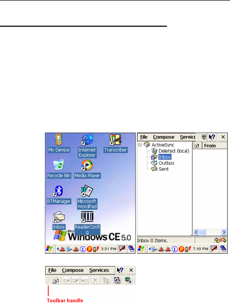
Chapter 5 107
5.4 Inbox
You can send and receive e-mail by connecting to a POP3 or IMAP4 server. Inbox provides
an e-mail service for each method you use.
In addition, you can synchronize the e-mail messages in Inbox with either Microsoft
Outlook or Microsoft Exchange Server on your computer through the default ActiveSync
mail service.
5.4.1 Create an E-mail Box
1. Double-tap the Inbox shortcut on the desktop.
Tap and drag the toolbar handle to move it under the menu bar.
2. Select Services > Options from the menu bar.
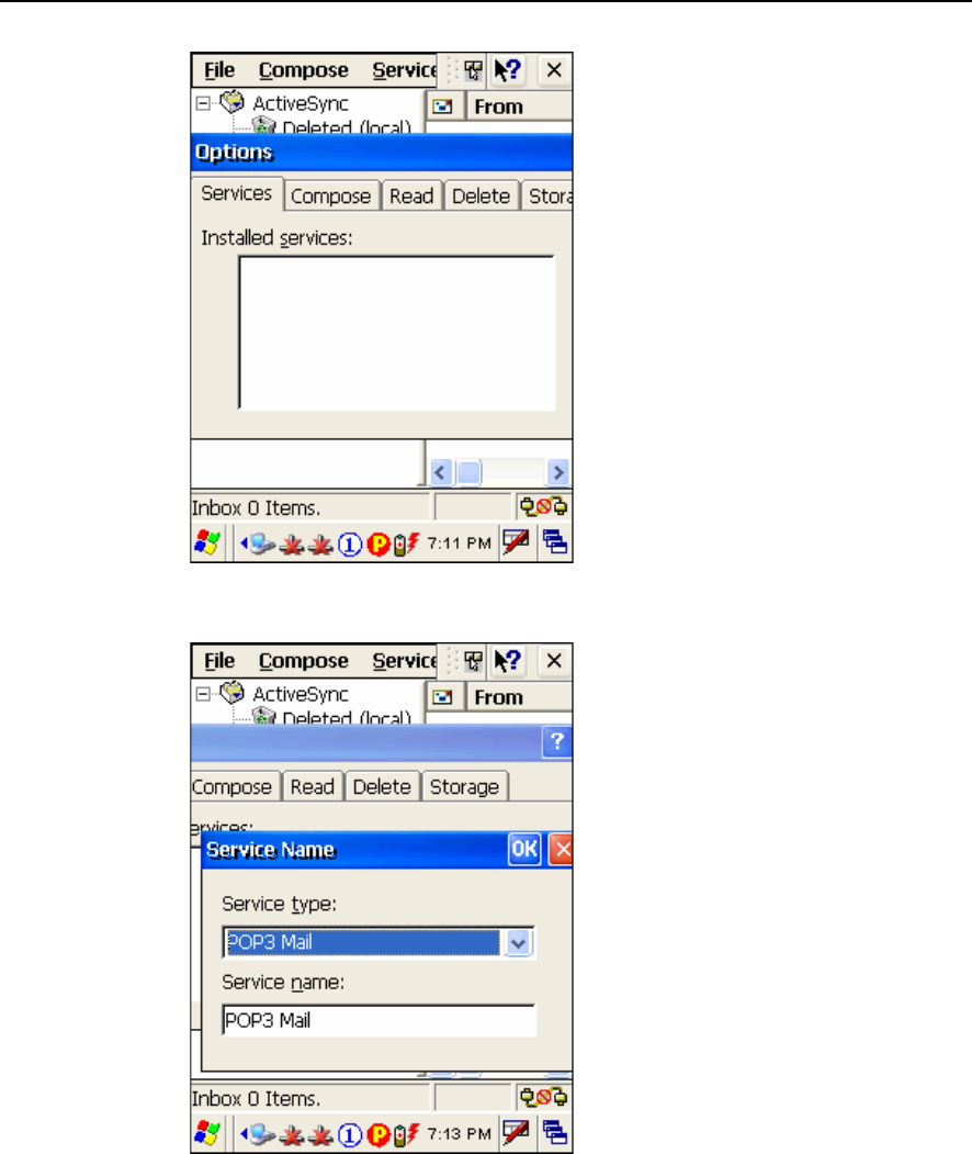
108 9500CE Terminal Reference Manual
3. Tap and drag the dialog box to show the right edge. Tap [Add] to create an e-mail
service.
4. In the Service Name dialog box, select POP3 Mail or IMAP4 Mail for the service type.
Change the name of e-mail service if necessary. Tap [OK].
5. Proceed with the POP3 or IMAP4 Mail Service Definition (from 1/3 to 3/3).
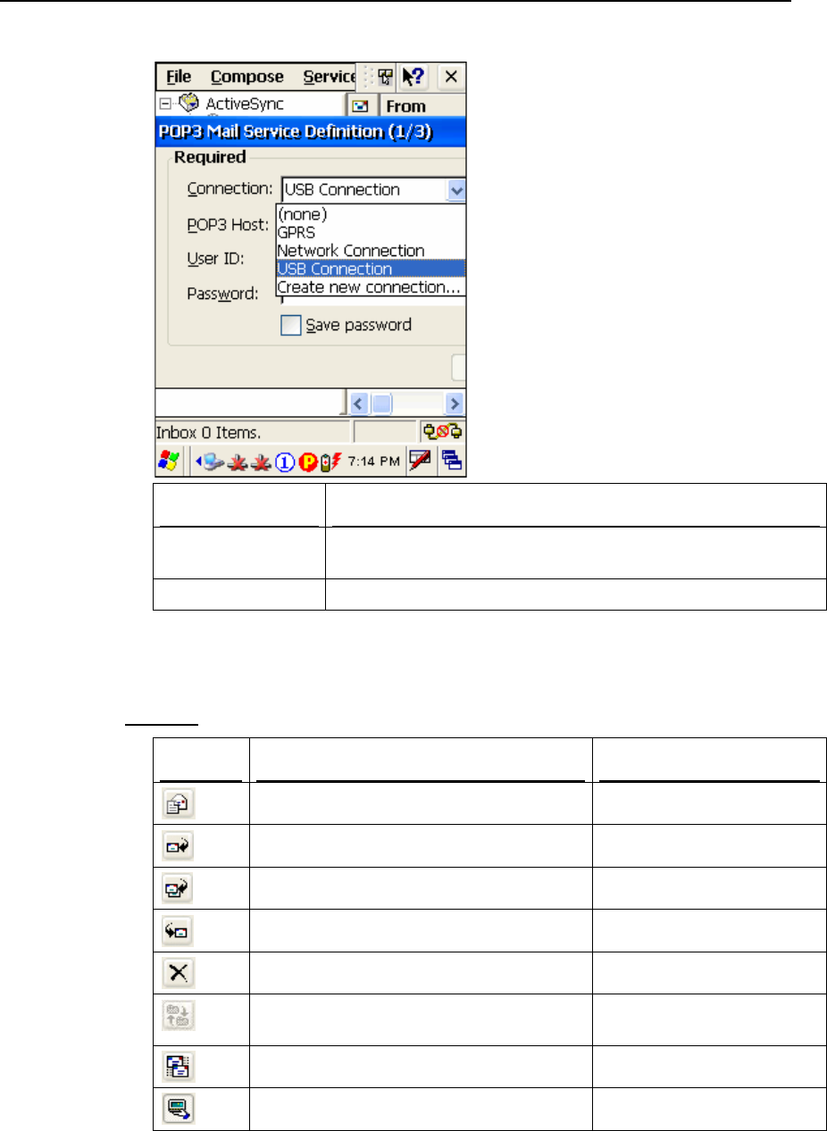
Chapter 5 109
Connection Description
Network Connection Send and Receive e-mail through Ethernet, 802.11b/g or Bluetooth
PAN connection.
USB Connection Send and Receive e-mail through USB connection via the cradle.
6. After you successfully create an e-mail service, you may start using it now.
Toolbar
Buttons Description See Also
Compose a new message Compose > New Message
Reply to sender Compose > Reply to Sender
Reply to all Compose > Reply to All
Forward this message Compose > Forward
Delete this message File > Delete
Synchronize folders (multiple mailboxes for
IMAP4 )
Services > Synchronize
Folders
Send and receive mail manually Services > Send/Receive Mail
Connect or disconnect Services > Connect
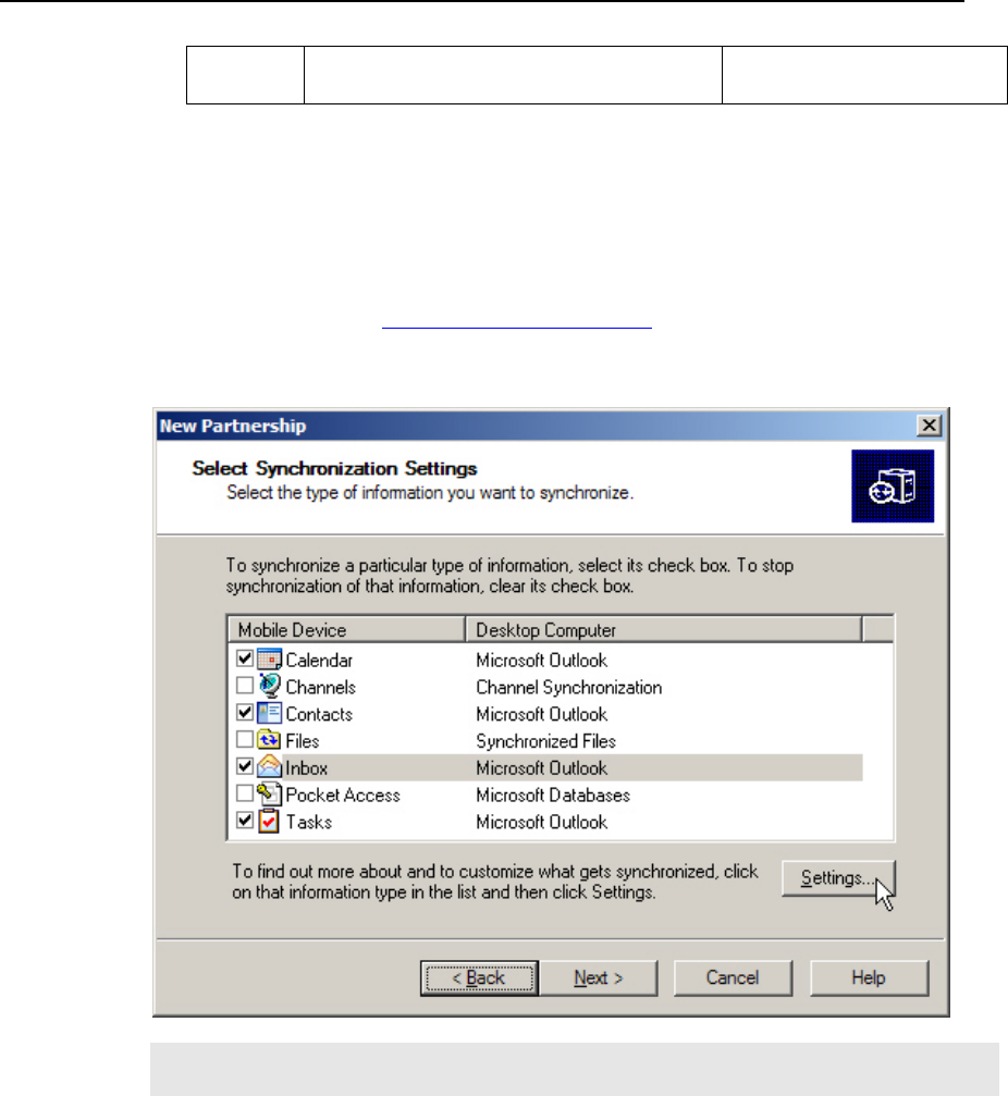
110 9500CE Terminal Reference Manual
When connected, it will send and receive
mail automatically.
5.4.2 Synchronize Inbox
When you seat the terminal in the cradle and connect it to your computer for the first time,
ActiveSync 3.7.1 will guide you through setting up a partnership between the terminal and
your computer. Refer to ActiveSync with a Computer.
Select the check box of Inbox as shown below, and click [Settings] to configure it.
Note: ActiveSync 4.x does not support Inbox Synchronization. We recommend that you
have ActiveSync 3.7.1 installed on your computer.

111
General
Main: Rechargeable 3.7 V, 4000 mAh Li-ion battery pack
Backup: Rechargeable 3.7 V, 110 mAh Lithium battery
Power
Adapter
(cradle):
Input - AC 110/220 V
Output - DC 6 V, 3.3 A
CPU Intel PXA270 at 520 MHz
ROM: 128 MB non-volatile NAND flash memory
Memory
RAM: 128 MB on-board SDRAM memory
Operating System Windows CE 5.0
Programming Visual Studio .NET 2003 with the Windows CE Utilities for Visual
Studio .NET 2003 Add-on Pack
eMbedded Visual C++ 4.0 SP4
a DLL file for reader configuration
Windows-based Application Generator (AG)
Physical
Enclosure Material: Rubber & ABS plastic
Dimensions: 230 mm (L) x 91 mm (W) x 63 mm (H)
Weight: Approx. 600 g (One battery pack included)
Reader: One scan engine (CCD/Laser/Long Range Laser/Extra Long
Range Laser/2D), and/or the RFID reader
Input Devices
Keypad: 27-key layout
Rubber keys with LED backlight
Type: Color transflective TFT display with LED backlight
Touch screen
Size: 3.5 inches
Display
Resolution: 240 x 320 pixels
LED: Tri-color LED
Speaker: Low power transducer type, 1 KHz to 4 KHz
Indicators
Vibrator: 9000 ± 2000 RPM, Max. 50 dB
Specifications

112 9500CE Terminal Reference Manual
USB
Client:
Peer-to-Peer connection via cradle (ActiveSync)
USB Host: For peripherals, such as a keyboard, mouse, storage card, etc.
Ethernet: 10/100 Mbps via cradle
Communications
WPAN /
WLAN:
Bluetooth Class 2
IEEE 802.11b/g
Environmental
Operating: 5% to 90% non-condensing
Humidity
Storage: 5% to 95% non-condensing
Temperature Operating: -10 to 50 °C
Storage: -20 to 60 °C
Shock Resistance 1.5 m, 5 drops per 6 sides
Splash/Dust
Resistance
IP 64
EMC Certification FCC, CE, C-Tick, TELEC, IC, NCC, BSMI, MIC

113
For the following 1D scan engine, you can select a desired scan mode.
CCD scan engine
Laser scan engine
ON OFFScan Mode
Always Press
trigger
once
Hold
trigger
Press
trigger
twice
Release
trigger
Press
trigger
once
Barcode
being
read
Time-
out
Continuous mode 9
Test mode 9
Repeat mode 9
Momentary mode 99
Alternate mode 99
Aiming mode 999
Laser mode 9999
Auto Off mode 9 99
Auto Power Off mode 9 9
APPENDIX I
Comparison of Scan Modes

114 9500CE Reference Manual
Continuous Mode
The reader is always scanning, but only one decoding is allowed for the same barcode. That is,
to read (i.e. scan and decode) the same barcode multiple times, the barcode has to be taken
away and replaced for new scanning.
Several modes have been developed based on this mode.
Test Mode
The reader is always scanning for testing purpose.
Comparing to the Continuous mode, it will decode repeatedly even with the same barcode
without re-approaching.
Repeat Mode
This mode is most useful when the same barcode is to be read many times. When the scan trigger is
pressed within one second after a successful reading, the same data will be re-transmitted without
actually reading the barcode. Such re-transmission can be activated as many times as needed, as
long as the time interval between each triggering does not exceed one second.
The reader is always scanning.
It will decode once for the same barcode and allow for re-transmission when triggering within
one second.
Momentary Mode
Hold down the scan trigger to start scanning.
The scanning continues until the trigger is released.
Alternate Mode
Press the scan trigger to start scanning.
The scanning continues until the trigger is pressed again.
Aiming Mode
This mode best applies when two barcodes are printed too close to each other. It is necessary to
take aim first to make sure the correct barcode will be scanned.
Press the scan trigger to aim at a barcode. Within one second, press the trigger again to decode
the barcode.
The scanning continues until one of the events happens:
(1) A barcode is read.
(2) The preset timeout expires.
Note: The system global variable AIMING_TIMEOUT can be used to change the default
one-second timeout interval for aiming. The unit for this variable is 5 ms.

Appendix I 115
Laser Mode
This mode is most often used on laser scanners.
Hold down the scan trigger to start scanning.
The scanning continues until one of the events happens:
(1) A barcode is read.
(2) The preset timeout expires.
(3) The trigger is released.
Auto Off Mode
This is the default mode.
The reader will start to scan once the scan trigger is pressed.
The scanning continues until one of the events happens:
(1) A barcode is read.
(2) The preset timeout expires.
Auto Power Off Mode
The reader will start to scan once the scan trigger is pressed.
The scanning continues until one of the events happens:
(1) The preset timeout expires.
Comparing to the Auto Off mode, the reader continues to scan whenever there is a successful
reading of barcode because its timeout period re-counts.