Cisco Linksys NWR04B WLAN Router (w/AP) User Manual
Cisco-Linksys, LLC WLAN Router (w/AP) Users Manual
UserManual.wiki
>
Cisco Linksys
>
NWR04B User Manual
Users Manual
Navigation menu
Upload a User Manual
Namespaces
Wiki Guide
HTML
PDF
Info
Views
User Manual
Discussion / Help
Navigation


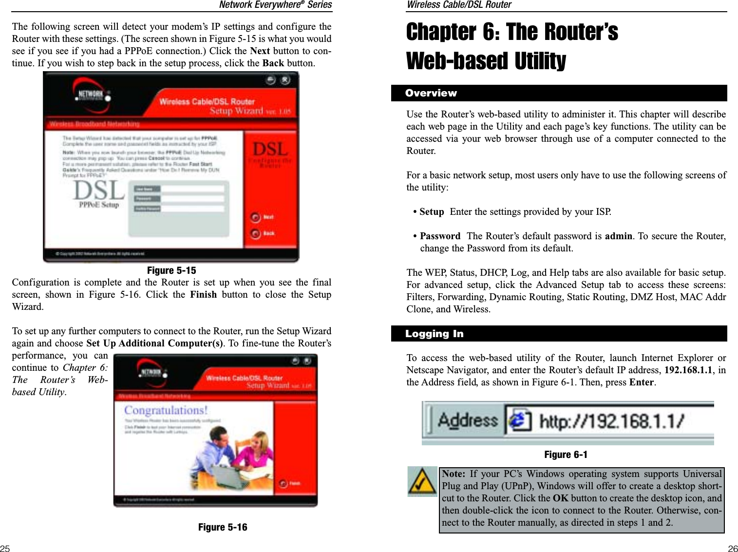


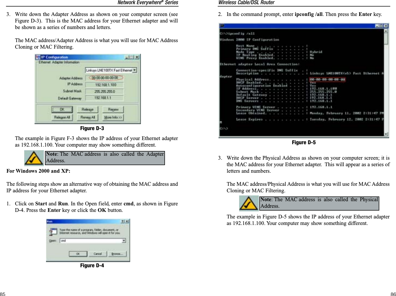
![Wireless Cable/DSL Router68Network Everywhere®Series67ting. The Internet user can then send a file to a user behind the Router.I set up an Unreal Tournament Server, but others on the LAN cannot join. What doI need to do? If you have a dedicated Unreal Tournament server running, youneed to create a static IP for each of the LAN computers and forward ports7777, 7778, 7779, 7780, 7781, and 27900 to the IP address of the server. Youcan also use a port forwarding range of 7777 ~ 27900. If you want to use theUT Server Admin, forward another port (8080 usually works well but is usedfor remote admin. You may have to disable this.), and then in the[UWeb.WebServer] section of the server.ini file, set the ListenPort to 8080 (tomatch the mapped port above) and ServerName to the IP assigned to theRouter from your ISP.Can multiple gamers on the LAN get on one game server and play simultaneouslywith just one public IP address? It depends on which network game or whatkind of game server you are using. For example, Unreal Tournament supportsmulti-login with one public IP.How do I get Half-Life: Team Fortressto work with the Router? The default clientport for Half-Life is 27005. The computers on your LAN need to have“+clientport 2700x” added to the HL shortcut command line; the x would be6, 7, 8, and on up. This lets multiple computers connect to the same server.One problem: Version 1.0.1.6 won’t let multiple computers with the same CDkey connect at the same time, even if on the same LAN (not a problem with1.0.1.3). As far as hosting games, the HL server does not need to be in theDMZ. Just forward port 27015 to the local IP address of the server comput-er. The web page hangs; downloads are corrupt, or nothing but junk characters arebeing displayed on the screen. What do I need to do? Force your Ethernetadapter to 10Mbps or half duplex mode, and turn off the “Auto-negotiate”feature of your Ethernet adapter as a temporary measure. (Please look at theNetwork Control Panel in your Ethernet adapter’s Advanced Properties tab.)Make sure that your proxy setting is disabled in the browser. Check our web-site at www.linksys.com for more information.If all else fails in the installation, what can I do? Reset the Router by holdingdown the reset button for about 30 seconds. Reset your cable or DSL modemby powering the unit off and then on. Obtain and flash the latest firmwarerelease that is readily available on the Network Everywhere website,www.networkeverywhere.com.What is the maximum number of IP addresses that the Router will support? TheRouter will support up to 253 IP addresses.Is IPSec Pass-Through supported by the Router? Yes, it is a built-in feature thatthe Router automatically enables.Where is the Router installed on the network? In a typical environment, theRouter is installed between the cable/DSL modem and the LAN. Plug theRouter into the cable/DSL modem’s Ethernet port.Does the Router support IPX or AppleTalk? No. TCP/IP is the only protocol stan-dard for the Internet and has become the global standard for communications.IPX, a NetWare communications protocol used only to route messages fromone node to another, and AppleTalk, a communications protocol used onApple and Macintosh networks, can be used for LAN to LAN connections,but those protocols cannot connect from Internet to LAN.Does the Router’s Internet port support 100 Mbps Ethernet? Because of the speedlimitations of broadband Internet connections, the Router’s current hardwaredesign supports 10 Mbps Ethernet on its Internet port. It does, of course, sup-port 100 Mbps over its LAN ports. What is Network Address Translation and what is it used for? Network AddressTranslation (NAT) translates multiple IP addresses on the private LAN to onepublic address that is sent out to the Internet. This adds a level of securitysince the address of a PC connected to the private LAN is never transmittedon the Internet. Furthermore, NAT allows the Router to be used with low costInternet accounts, such as DSL or cable modems, when only one TCP/IPaddress is provided by the ISP. The user may have many private addressesbehind this single address provided by the ISP.Does the Router support any operating system other than Windows 98 SE,Windows 2000, Windows NT, or Windows XP? Yes, but Network Everywheredoes not, at this time, provide technical support for setup, configuration ortroubleshooting of any non-Windows operating systems.Does the Router support ICQ send file? Yes, with the following fix: click ICQmenu -> preference -> connections tab->, and check I am behind a fire-wall or proxy. Then set the firewall time-out to 80 seconds in the firewall set-Frequently Asked Questions](https://usermanual.wiki/Cisco-Linksys/NWR04B/User-Guide-290204-Page-37.png)
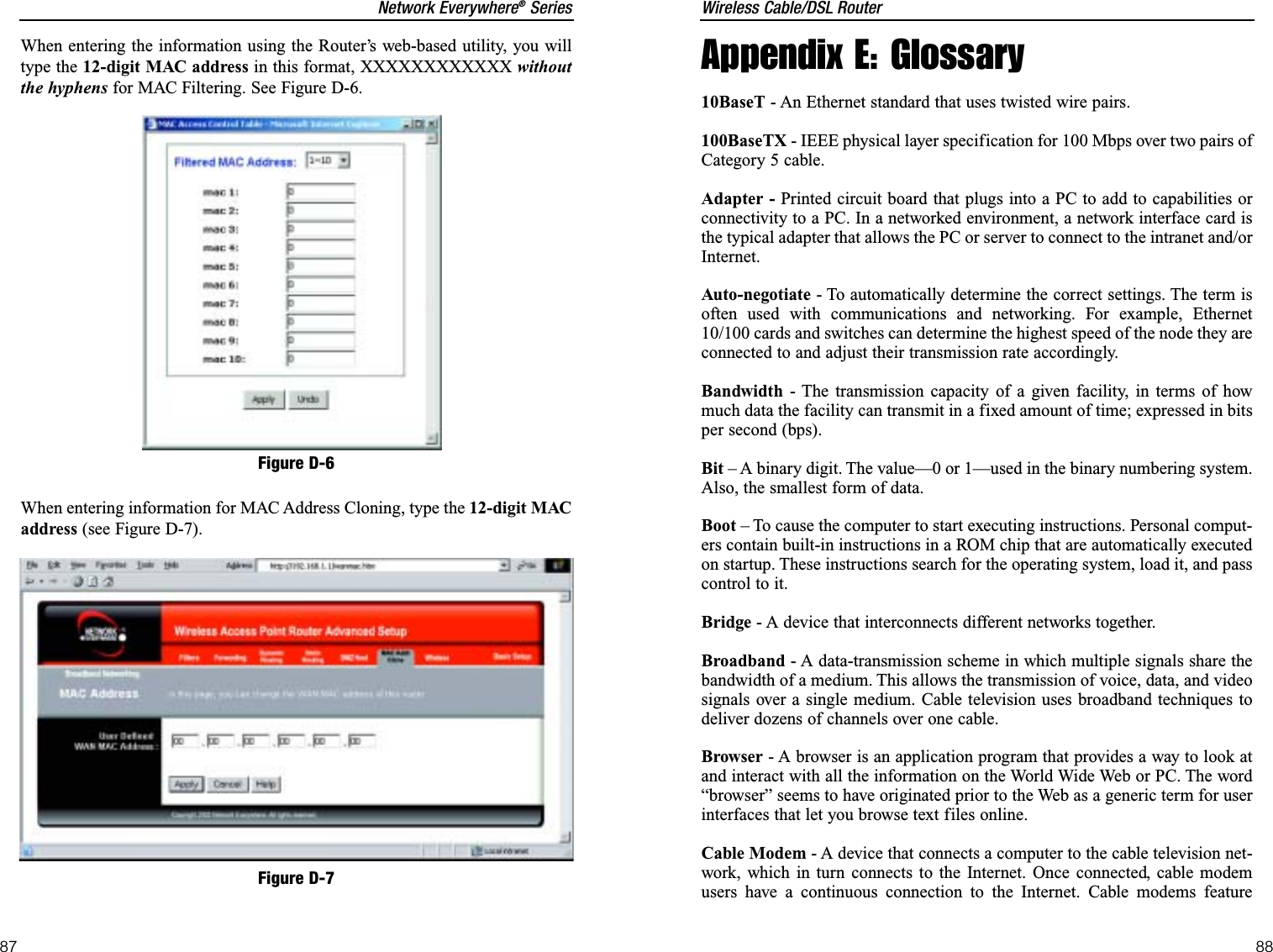
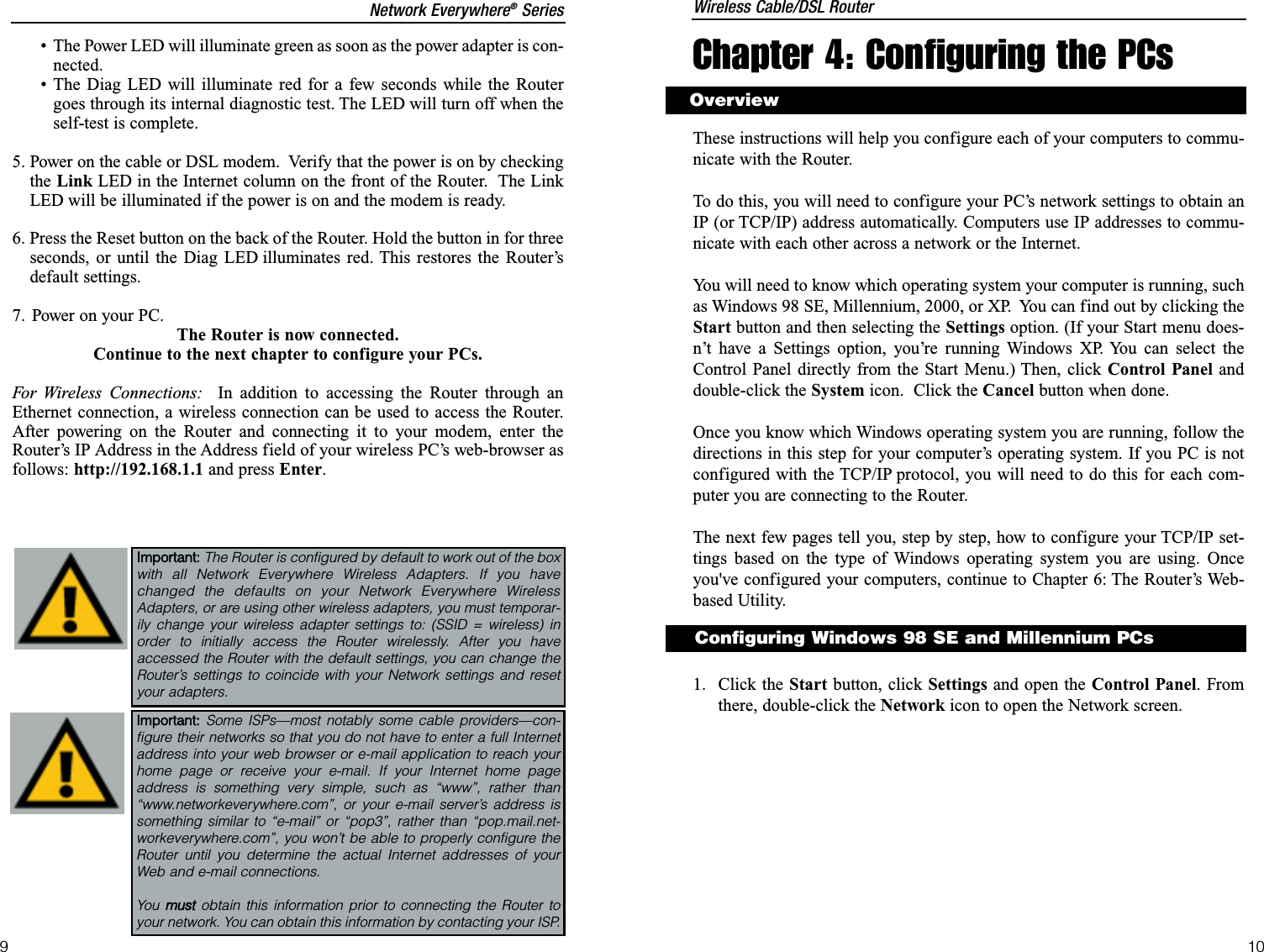
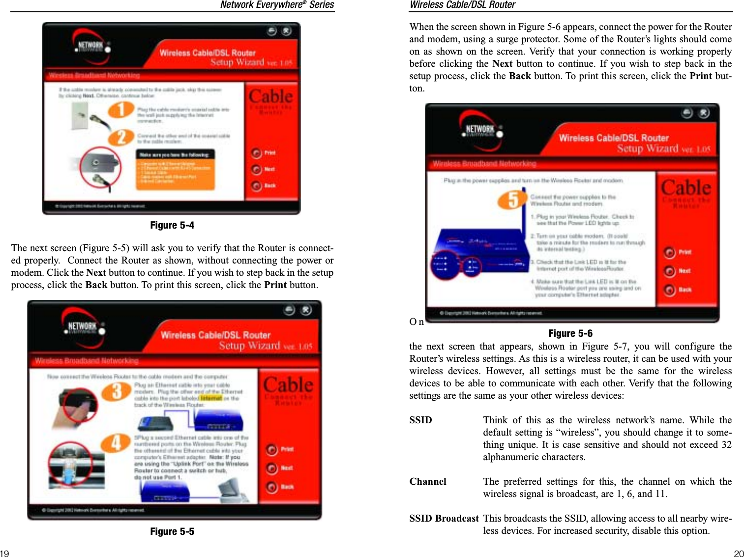
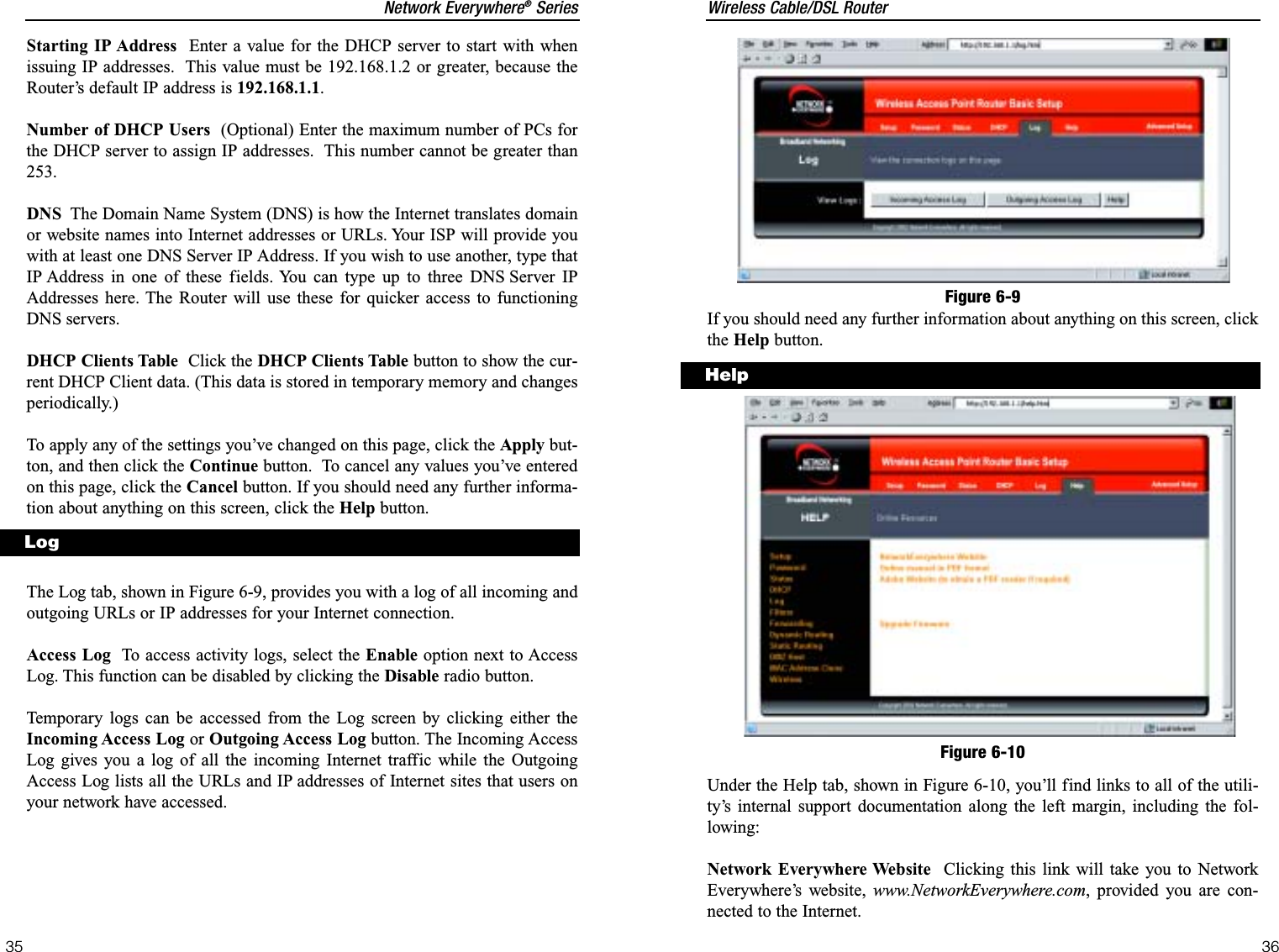
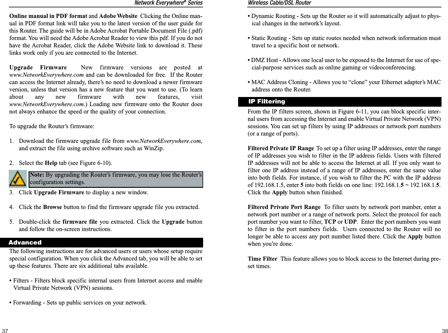
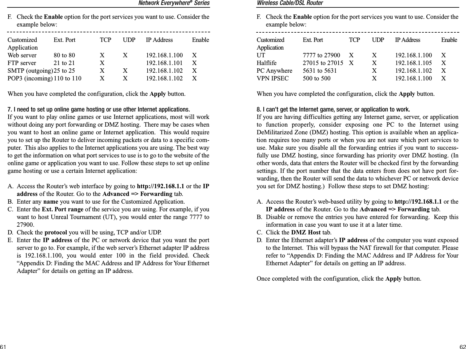
![Wireless Cable/DSL Router74Network Everywhere®Series733. At the DOS command prompt, type “ping mail” (assuming that the loca-tion for which you’re trying to find an IP address is configured as “mail”).Press Enter. Information such as the following data, taken from a ping ofMicrosoft Network’s e-mail server, will be displayed.4. Write down the IP address returned by the ping command. (In theexample above: 24.53.32.4.) This IP address is the actual IP address of theserver “mail,” or any other word or value you have pinged.Step Two: Pinging for a Web AddressWhile the IP address returned above would work as your e-mail server address,it may not be permanent. IP addresses change all the time. Web addresses, how-ever, usually don’t. Because of this, you’re likely to have fewer problems byconfiguring your system with web addresses rather than IP addresses. Followthe instructions below to find the web address assigned to the IP address youjust pinged.1. At the DOS command prompt, type “ping -a 24.53.32.4,” where24.53.32.4 is the IP address you just pinged. Information such as the fol-lowing data will be displayed.C:\>ping mailPinging mail [24.53.32.4] with 32 bytes of data:Reply from 24.53.32.4: bytes=32 time<10ms TTL=128Reply from 24.53.32.4: bytes=32 time<10ms TTL=128Reply from 24.53.32.4: bytes=32 time<10ms TTL=128Reply from 24.53.32.4: bytes=32 time<10ms TTL=128Ping statistics for 24.53.32.4:Packets: Sent = 4, Received = 4, Lost = 0 (0%loss),Approximate round trip times in milli-seconds:Minimum = 0ms, Maximum = 0ms, Average = 0msAppendix B: How to Ping Your ISP’sE-mail and Web AddressesVirtually all Internet addresses are configured with words or characters (i.e.,www.networkeverywhere.com, www.yahoo.com, etc.) In actuality, however,these Internet addresses are assigned to IP addresses, which are the trueaddresses on the Internet.IP and web addresses, however, can sometimes be long and hard to remember.Because of this, certain ISPs will shorten their server addresses to single wordsor codes on their users’ web browser or e-mail configurations. If your ISP’s e-mail and web server addresses are configured with single words (“www,” “e-mail,” “home,” “pop3,” etc.) rather than whole Internet Addresses or IPAddresses, the Router may have problems sending or receiving mail andaccessing the Internet. This happens because the Router has not been config-ured by your ISP to accept their abbreviated server addresses.The solution is to determine the true web addresses behind your ISP’s codewords. You can determine the IP and web addresses of your ISP’s servers by“pinging” them.Step One: Pinging an IP AddressThe first step to determining your ISP’s web and e-mail server address is toping its IP address.1. Power on the computer and the cable or DSL modem, and restore thenetwork configuration set by your ISP if you have since changed it.2. Click Start, then Run, and type “command.” This will bring up the DOSwindow.Note: If you don’t have your ISP’s web and e-mail IP addresses, you musteither get them from your ISP or follow these steps prior to connecting theRouter to your network.](https://usermanual.wiki/Cisco-Linksys/NWR04B/User-Guide-290204-Page-40.png)
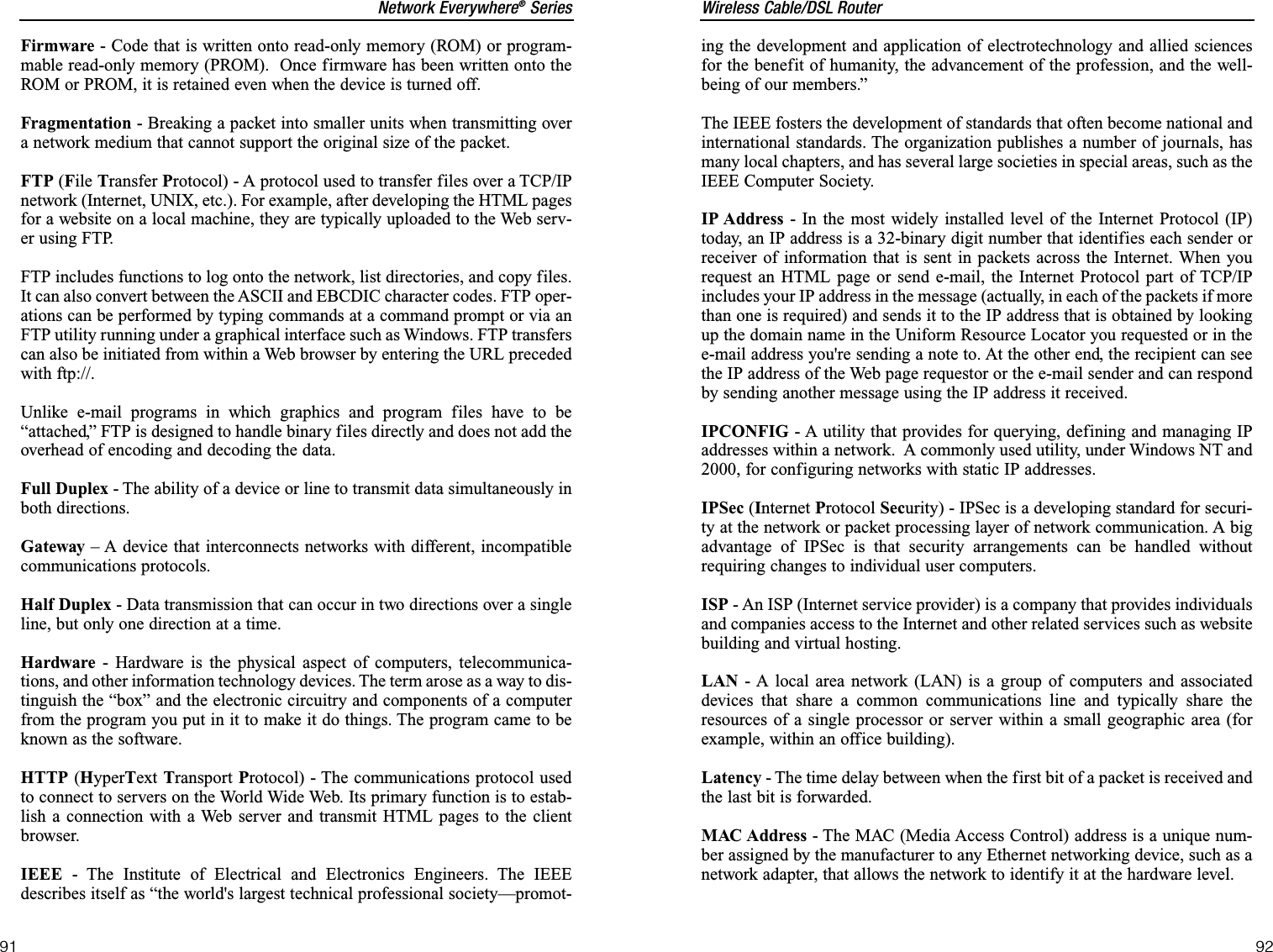
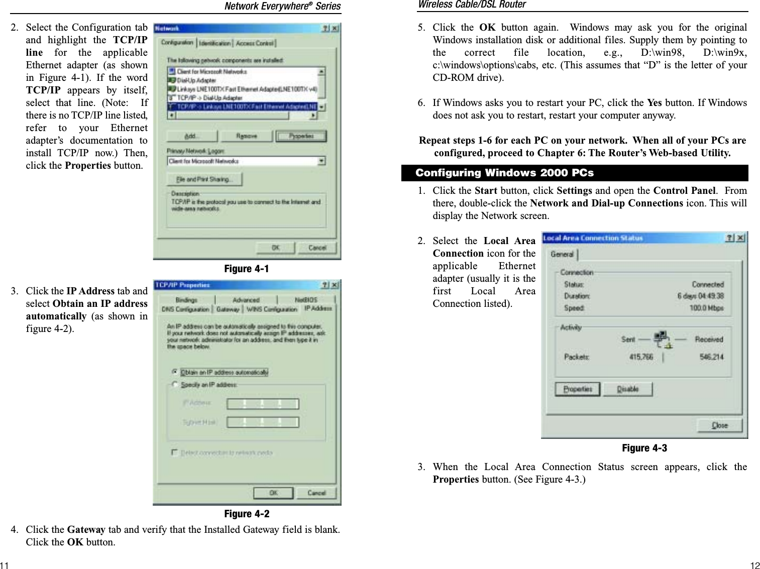
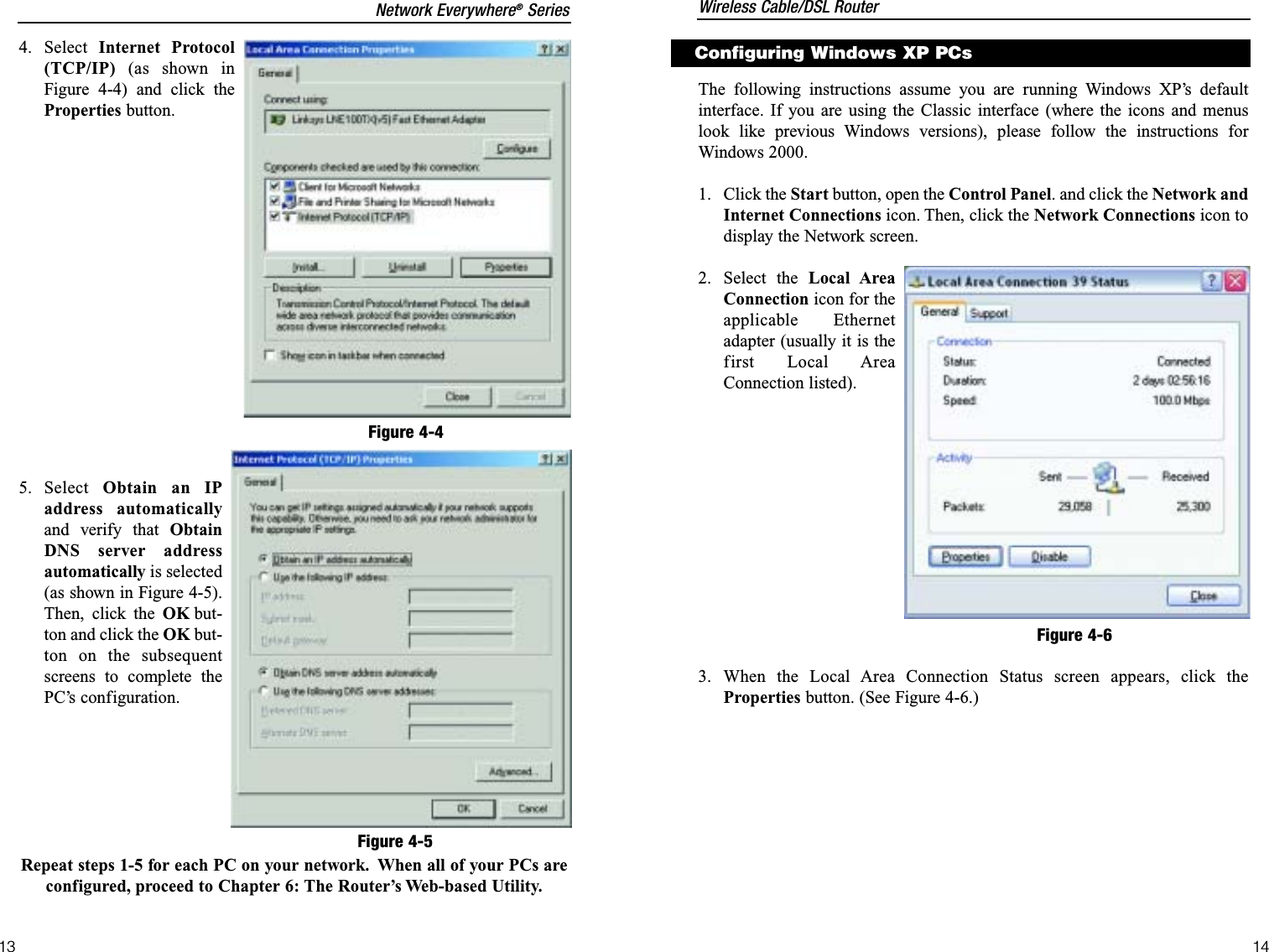
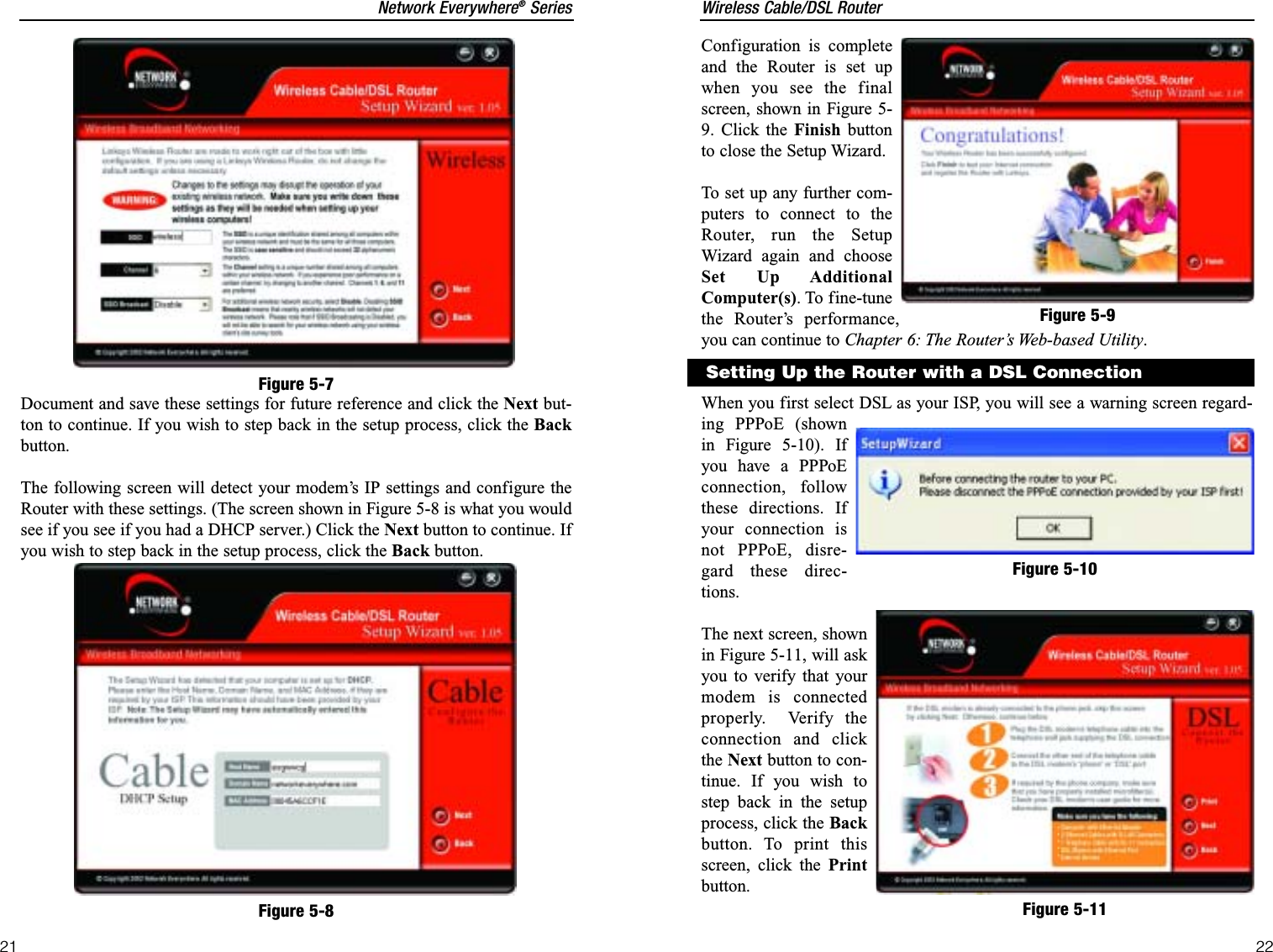
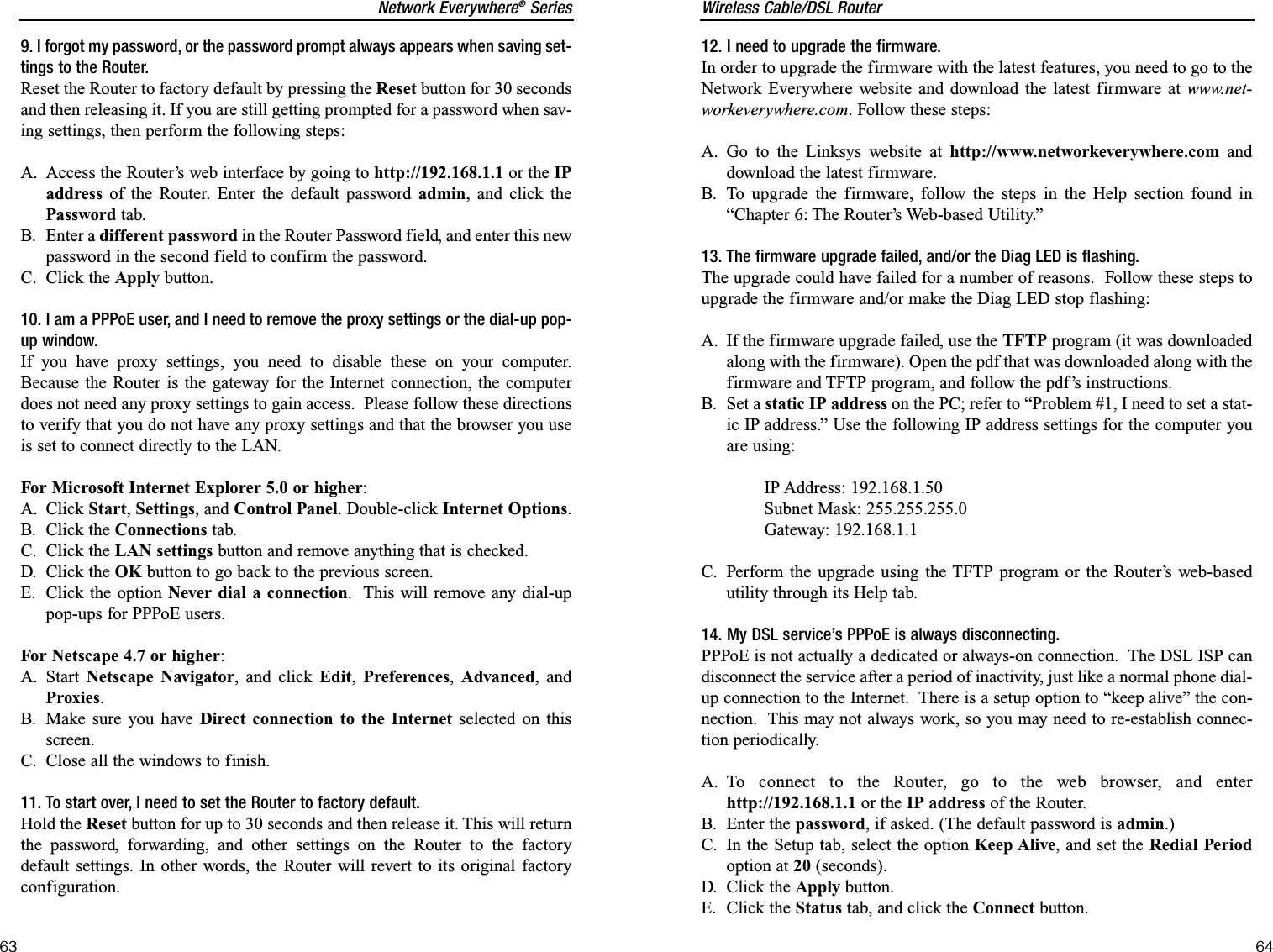
![Wireless Cable/DSL Router76Network Everywhere®Series75Appendix C: Configuring WirelessSecurityAn acronym for Wired Equivalent Privacy, WEP is an encryption method usedto protect your wireless data communications. WEP uses a combination of 64-bit or 128-bit keys to provide access control to your network and encryptionsecurity for every data transmission. To decode a data transmission, each pointin a network must use an identical 64-bit or 128-bit key. Higher encryption lev-els mean higher levels of security, but due to the complexity of the encryption,they may mean decreased network performance.You may also have heard the term “40-bit” used in conjunction with WEPencryption. This is simply another term for 64-bit WEP encryption. This levelof WEP encryption has been called 40-bit because it uses a 40-bit secret keyalong with a 24-bit Initialization Vector (40 + 24 = 64). Wireless vendors mayuse either name. Network Everywhere uses the term “64-bit” when referringto this level of encryption.Make sure your wireless network is functioning before attempting to configureWEP encryption.A 128-bit WEP encrypted wireless network will NOT communicate with a 64-bit WEP encrypted wireless network. Therefore, make sure that all of yourwireless devices are using the same encryption level. All wireless devices com-plying with the 802.11b standard will support 64-bit WEP.In addition to enabling WEP, Network Everywhere also recommends the fol-lowing security implementations:•Changing the SSID from the default “wireless”•Changing the WEP key regularlyNote: WEP encryption is an additional data securi-ty measure and not essential for router operation.Note: In order for WEP Encryption to be enabled, wireless functions mustfirst be enabled. Select Enable under the Wireless section before proceeding.2. Write down the web address returned by the ping command (in theexample above: mail.msnv3.occa.home.com.). This web address is the webaddress assigned to the IP address you just pinged. While the IP address of“mail” could conceivably change, it is likely that this web address will not.3. Replace your ISP’s abbreviated server address with this extended webaddress in the corresponding Internet application (web browser, e-mailapplication, etc.).Once you have replaced the brief server address with the true server address,the Router should have no problem accessing the Internet through that Internetapplication.C:\>ping -a 24.53.32.4Pinging mail.msnv3.occa.home.com [24.53.32.4] with32 bytes of data:Reply from 24.53.32.4: bytes=32 time<10ms TTL=127Reply from 24.53.32.4: bytes=32 time<10ms TTL=127Reply from 24.53.32.4: bytes=32 time<10ms TTL=127Reply from 24.53.32.4: bytes=32 time<10ms TTL=127Ping statistics for 24.53.32.4:Packets: Sent = 4, Received = 4, Lost = 0 (0%loss),Approximate round trip times in milli-seconds:Minimum = 0ms, Maximum = 0ms, Average = 0ms](https://usermanual.wiki/Cisco-Linksys/NWR04B/User-Guide-290204-Page-41.png)