Cisco Linksys NWR04B WLAN Router (w/AP) User Manual
Cisco-Linksys, LLC WLAN Router (w/AP) Users Manual
Users Manual

---Reorient or relocate the receiving antenna.
---Increase the separation between the equipment and receiver.
---Connect the equipment into an outlet on a circuit different from that to which the receiv-
er is connected.
---Consult the dealer or an experienced radio/TV technician for help.
Regulatory information / Disclaimers
Installation and use of this Wireless LAN device must be in strict accordance with the
instructions included in the user documentation provided with the product. Any changes
or modifications (including the antennas) made to this device that are not expressly
approved by the manufacturer may void the user's authority to operate the equipment.
The manufacturer is not responsible for any radio or television interference caused by
unauthorized modification of this device, or the substitution of the connecting cables and
equipment other than manufacturer specified. It is the responsibility of the user to correct
any interference caused by such unauthorized modification, substitution or attachment.
Manufacturer and its authorized resellers or distributors will assume no liability for any
damage or violation of government regulations arising from failing to comply with these
guidelines.
CAUTION: To maintain compliance with FCC's RF exposure guidelines, this equipment
should be installed and operated with minimum distance 20 cm between the radiator and
your body. Use on the supplied antenna. Unauthorized antenna, modification, or attach-
ments could damage the transmitter and may violate FCC regulations.
MPE Statement (Safety Information)
Your device contains a low power transmitter. When device is transmitted it sends out
Radio Frequency (RF) signal.
Safety Information
In order to maintain compliance with the FCC RF exposure guidelines, this equipment
should be installed and operated with minimum distance 20 cm between the radiator and
your body. Use only with supplied antenna. Unauthorized antenna, modification, or
attachments could damage the transmitter and may violate FCC regulations.
Caution Statement of the FCC Radio Frequency Exposure
This Wireless LAN radio device has been evaluated under FCC Bulletin OET 65C and
found compliant to the requirements as set forth in CFR 47 Sections 2.1091, 2.1093, and
15.247(b)(4) addressing RF Exposure from radio frequency devices. The radiation out-
put power of this Wireless LAN device is far below the FCC radio frequency exposure
limits. Nevertheless, this device shall be used in such a manner that the potential for
human contact during normal operation-as a mobile or portable device but use in a
body-worn way is strictly prohibit. When using this device, a certain separation distance
between antenna and nearby persons has to be kept to ensure RF exposure compliance.
In order to comply with the RF exposure limits established in the ANSI C95.1 standards,
the distance between the antennas and the user should not be less than 20 cm.
UG-NWR04B-110602NC KL
COPYRIGHT & TRADEMARKS
Copyright © 2002 Network Everywhere, All Rights Reserved. Network Everywhere and
Linksys are registered trademarks of Linksys. Microsoft, Windows, and the Windows
logo are registered trademarks of Microsoft Corporation. All other trademarks and brand
names are the property of their respective proprietors.
LIMITED WARRANTY
Network Everywhere guarantees that every Wireless Cable/DSL Router will be free from
physical defects in material and workmanship for one year from the date of purchase,
when used within the limits set forth in the Specifications section of this User Guide. If the
product proves defective during this warranty period, call Network Everywhere Technical
Support in order to obtain a Return Authorization number. BE SURE TO HAVE YOUR
PROOF OF PURCHASE ON HAND WHEN CALLING. When returning a product, mark
the Return Authorization number clearly on the outside of the package and include a
copy of your original proof of purchase. RETURN REQUESTS CANNOT BE PROCESSED
WITHOUT PROOF OF PURCHASE. All customers located outside of the United States
of America and Canada shall be held responsible for shipping and handling charges.
IN NO EVENT SHALL NETWORK EVERYWHERE’S LIABILITY EXCEED THE PRICE PAID
FOR THE PRODUCT FROM DIRECT, INDIRECT, SPECIAL, INCIDENTAL, OR CONSE-
QUENTIAL DAMAGES RESULTING FROM THE USE OF THE PRODUCT, ITS ACCOM-
PANYING SOFTWARE, OR ITS DOCUMENTATION. NETWORK EVERYWHERE OFFERS
NO REFUNDS FOR ITS PRODUCTS. Network Everywhere makes no warranty or repre-
sentation, expressed, implied, or statutory, with respect to its products or the contents or
use of this documentation and all accompanying software, and specifically disclaims its
quality, performance, merchantability, or fitness for any particular purpose. Network
Everywhere reserves the right to revise or update its products, software, or documenta-
tion without obligation to notify any individual or entity. Please direct all inquiries to:
Network Everywhere P.O. Box 18558, Irvine, CA 92623.
FCC Certifications
You are cautioned that any changes or modifications not expressly approved in this man-
ual could void your authorization to use the device.
CAUTION: Any changes or modifications not expressly approved by the party responsi-
ble for compliance could void the user's authority to operate the equipment.
Prohibition of co-location
This device must not be co-located or operating in conjunction with any other antenna or
transmitter.
15.105 Federal Communications Commission (FCC) Requirements, Part 15
This equipment has been tested and found to comply with the limits for a class B digital
device, pursuant to part 15 of the FCC Rules. These limits are designed to provide rea-
sonable protection against harmful interference in a residential installation.
This equipment generates, uses and can radiate radio frequency energy and, if not
installed and used in accordance with the instructions, may cause harmful interference
to radio communications. However, there is no guarantee that interference will not occur
in a particular installation. If this equipment does cause harmful interference to radio or
television reception, which can be determined by turning the equipment off and on, the
user is encouraged to try to correct the interference by one or more of the following
measures:

Wireless Cable/DSL Router
Chapter 6: The Router’s Web-based Utility 26
Overview 26
Logging In 26
Setup 27
Password 32
Status 33
DHCP 34
Log 35
Help 36
Advanced 37
IP Filtering 38
Forwarding 41
Dynamic Routing 47
Static Routing 48
DMZ Host 50
MAC Address Clone 51
Wireless 52
Appendix A: Troubleshooting 55
Common Problems and Solutions 55
Frequently Asked Questions 67
Appendix B: How to Ping Your ISP’s E-mail and Web Addresses 73
Appendix C: Configuring Wireless Security 76
Configuring Wireless Security in Windows XP 79
Appendix D: Finding the MAC Address
and IP Address for Your Ethernet Adapter 84
Appendix E: Glossary 88
Appendix F: Specifications 97
Environmental 97
Appendix G: Warranty Information 98
Appendix H: Contact Information 99
Network Everywhere®Series
Table of Contents
Chapter 1: Introduction 1
The Wireless Cable/DSL Router 1
Features 1
An Introduction to LANs and WANs 2
IP Addresses 2
The Router’s Ports 4
The Router’s LEDs 5
Chapter 2: Planning Your Wireless Network 7
Network Topology 7
Roaming 7
Chapter 3: Connecting the Router 8
Before You Start 8
Connecting Your Hardware Together and Booting Up 8
Chapter 4: Configuring the PCs 10
Overview 10
Configuring Windows 98 SE and Millennium PCs 10
Configuring Windows 2000 PCs 12
Configuring Windows XP PCs 14
Chapter 5: Using the Setup Wizard 16
Before You Start 16
The Setup Wizard’s Title Screen 16
Preparing to Set Up 17
Setting Up the Router with a Cable Connection 18
Setting Up the Router with a DSL Connection 22

Wireless Cable/DSL Router
Chapter 1: Introduction
Think of the Network Everywhere Wireless Cable/DSL Router as a kind of
"splitter" for your Internet connection. Just connect your DSL or Cable
Modem to the Router, and all the computers in your household can share the
Internet -- all at the same time. You can connect your home computers to the
Router with Ethernet cables, or put wireless network adapters in them and com-
municate over radio waves, saving the trouble and expense of running cables
through your house.
Once your computers are connected to the Router, they can communicate with
each other too, sharing resources and files. All your computers can print on a
shared printer connected anywhere in the house. And your computers can share
all kinds of files -- music, digital pictures, and documents. Keep all your dig-
ital music on one computer, and listen to it anywhere in the house. Organize
all of your family's digital pictures in one place, to simplify finding the ones
you want, and easing backup to CD-R. Utilize extra free space on one com-
puter when another's hard drive starts to fill up.
Your home network is secure, too. All wireless communications are protected
by 128-bit encryption. Internet Firewall packet filters keep intruders out, and
block attacks. Parental Controls help you protect your family.It's all easier than
you think -- the included Setup Wizard takes you through configuring your net-
work, step by step. With the Network Everywhere Wireless Cable/DSL Router
at the heart of your home network, you don't need to be a networking genius to
share printers, files, and your Internet connection -- with or without wires.
• Supports Universal Plug and Play (UPnP)
• Internet access logging
• Easy to use setup utility or configure through your networked PC’s Web
browser
• Supports SNTP (Simple Network Time Protocol)
• Internet access control (Parental Controls), by time-of-day or by day of the
week
• Port Trigger function for Internet applications with special requirements
• Remote administration and upgrade feature
• Supports static routing and dynamic routing protocol RIP1/RIP2
• Denial of Service(Dos) Prevention
• Context sensitive configuration help
2
The Wireless Cable/DSL Router
Features
Network Everywhere®Series
Simply put, a router is a network device that connects two networks together.
In this instance, the Router connects your Local Area Network (LAN), or the
group of PCs in your home or office, to the Wide Area Network (WAN) that is
the Internet. The Router processes and regulates the data that travels between
these two networks.
Think of the Router as a network device with two sides. The first side is made
up of your private Local Area Network (LAN) of PCs. The other, public side
is the Internet, or the Wide Area Network (WAN), outside of your home or
office.
The Router’s firewall (NAT) protects your network of PCs so users on the pub-
lic, Internet side cannot “see” your PCs. This is how your LAN, or network,
remains private. The Router protects your network by inspecting the first pack-
et coming in from the Internet port before delivery to the final destination on
the LAN port. The Router inspects Internet port services like the web server,
ftp server, or other Internet applications, and, if allowed, it will forward the
packet to the appropriate PC on the LAN side.
What’s an IP Address?
IP stands for Internet Protocol. Every device on an IP-based network, includ-
ing PCs, print servers, and routers, requires an IP address to identify its “loca-
tion,” or address, on the network. This applies to both the Internet and LAN
connections.
There are two ways of assigning an IP address to your network devices.
Static IP Addresses
A static IP address is a fixed IP address that you assign manually to a PC or
other device on the network. Since a static IP address remains valid until you
disable it, static IP addressing insures that the device assigned it will have that
same IP address until you change it. Static IP addresses are commonly used
with network devices such as server PCs or print servers.
If you use the Router to share your cable or DSL Internet connection, contact
your ISP to find out if they have assigned a static IP address to your account.
If so, you will need that static IP address when configuring the Router. You can
get the information from your ISP.
IP Addresses
An Introduction to LANs and WANs
1
Dynamic IP Addresses
A dynamic IP address is automatically assigned to a device on the network,
such as PCs and print servers. These IP addresses are called “dynamic”
because they are only temporarily assigned to the PC or device. After a certain
time period, they expire and may change. If a PC logs on to the network (or the
Internet) and its dynamic IP address has expired, the DHCP server will assign
it a new dynamic IP address.
For DSL users, many ISPs may require you to log on with a user name and
password to gain access to the Internet. This is called “Point to Point Protocol
over Ethernet” or PPPoE. PPPoE is similar to a dial-up connection but does not
have a phone number to dial into, and PPPoE is a dedicated high-speed con-
nection. PPPoE also will provide the Router with a dynamic IP address to
establish a connection to the Internet.
DHCP (Dynamic Host Configuration Protocol) Servers
DHCP frees you from having to assign IP addresses manually every time a new
user is added to your network. PCs and other network devices using dynamic
IP addressing are assigned a new IP address by a DHCP server. The PC or net-
work device obtaining an IP address is called the DHCP client. The Router’s
Internet port is, by default, set as a DHCP client.
DHCP servers can either be a designated PC on the network or another network
device, such as the Router. By default, a DHCP server is enabled on your
Router’s LAN ports. If you already have a DHCP server running on your net-
work, you must disable one of the two DHCP servers. If you run more than one
DHCP server on your network, you will experience network errors, such as
conflicting IP addresses. To disable the Router’s DHCP function, see the
DHCP section in Chapter 6: The Router’s Web-Based Utility.
Note: Even if you assign a static IP address to a PC, other PCs can still use
DHCP’s dynamic IP addressing, as long as the static IP is not within the
DHCP range of the LAN IP Address.
If the Router’s DHCP function fails to provide a dynamic IP address for any
reason, please refer to Appendix A: Troubleshooting.
The
Router’s rear panel (as shown in Figure 1-1) is where all of its connections are
made.
Internet The Internet Port is where you will connect your cable or
DSL modem with an Ethernet cable. Your modem con-
nection will not work from any other port.
Ports 4, 3, 2 These four LAN (Local Area Network) ports are where
you will connect networked devices, such as PCs, print
servers, and any other Ethernet devices you want to put
on your network. If Port 1 is being used, the Uplink Port
will not work.
Port 1/Uplink Port The Uplink Port is where you can expand your network
by connecting to a switch. Uplinking to a switch is done
by simply running a cable from the Uplink Port to the
other device. The Uplink Port is shared with Port 1.
Pushing in the Uplink button allows this port to be used
as the Uplink port. If the Uplink button is not pushed in,
this port functions the same as Ports 4, 3, and 2.
Power The Power Port is where you will connect the included
AC Power adapter.
Figure 1-1
The Router’s Ports
Note: Since the Router is a device that connects two networks, it needs two
IP addresses—one for the LAN side, and one for the Internet side. In this
User Guide, you’ll see references to the “Internet IP address” and the “LAN
IP address.”
Since the Router has firewall security (NAT), only the Router’s Internet IP
address can be seen from the Internet.
However, even the Internet IP address can be blocked, so that the Router and
network seem invisible to the Internet—This is shown in the Filters section in
“Chapter 6: The Routers Web-Based Utility”.
Wireless Cable/DSL Router
Network Everywhere®Series
43
The LAN Indicators, shown in Figure 1-2, show the status of information being
transmitted within your local network
WLAN Act Green. This LED indicates wireless activity.
WLAN Link Green. This LED indicates that the Router’s wireless func-
tions have been enabled through the Web-based utility.
Power Green. This LED indicates that the Router’s power is on.
Link/Act Green. This LED serves two purposes. When this LED is lit
continuously, this indicates that the Router is connected to a
device through the corresponding port (1, 2, 3, or 4). A blink-
ing LED indicates that the Router is actively sending or
receiving data over that port. When the Uplink Port is in use,
the LED for Port 1 will be lit continuously.
The Router’s LEDs
The RReset BButton
Pressing the Reset Button and holding it in for a few seconds will clear all
of the Router’s data and restore the factory defaults. This should be done
only if you are experiencing heavy routing problems, and only after you
have exhausted all of the other troubleshooting options. By resetting the
Router, you run the risk of creating conflicts between your PCs’ actual IP
Addresses and what the Router thinks their IP Addresses should be. You
may be forced to reboot each network PC.
If the Router locks up, simply press the reset button or power it down for
three to five seconds by removing the power cable from the Router’s
Power Port. Leaving the power off for too long could result in the loss of
network connections.
Figure 1-2
Full/Col Green. This LED also serves two purposes. When this LED
is lit continuously, the connection made through the corre-
sponding port is running in Full Duplex mode. A blinking
LED indicates that the connection is experiencing collisions.
Infrequent collisions are normal. If this LED blinks too
often, there may be a problem with your connection. Refer to
the Troubleshooting Appendix if you think there is a prob-
lem.
100 Orange. This LED indicates when a successful 100Mbps
connection is made through the corresponding port.
The Internet indicators, shown in Figure 1-2, show the status of information
being transmitted to and from the Internet.
Link Green. This LED indicates a connection between the Router
and your broadband device or network.
Act Green. This LED blinks when the Router is sending or
receiving data over the broadband (Internet) port.
Diag Red. This LED indicates the Router’s self-diagnosis mode
during boot-up and restart. It will turn off upon completing
the diagnosis. If this LED stays on for an abnormally long
period of time, refer to the Troubleshooting Appendix.
Wireless Cable/DSL Router
Network Everywhere®Series
65

Chapter 2: Planning Your Wireless
Network
A wireless LAN is exactly like a regular LAN, except that each computer in the
LAN uses a wireless adapter to connect to the network through a wireless con-
nection. Computers in a wireless LAN must be configured to share the same
radio channel.
The wireless adapter provides LAN access for wireless workstations. An inte-
grated wireless and wired LAN is called an Infrastructure configuration. A
group of wireless adapter users and this Router compose a Basic Service Set
(BSS). Each PC equipped with a wireless adapter in a BSS can talk to any
computer in a wired LAN infrastructure via this Router.
An infrastructure configuration extends the accessibility of a PC with a wire-
less adapter to a wired LAN, and doubles the effective wireless transmission
range for two PCs equipped with a wireless adapter Since this Router is able
to forward data within its BSS, the effective transmission range in an infra-
structure LAN is doubled.
Infrastructure mode also supports roaming capabilities for mobile users. More
than one BSS can be configured as an Extended Service Set (ESS). This con-
tinuous network allows users to roam freely within an ESS. All PCs that are
equipped with a wireless adapter, and are within one ESS, must be configured
with the same ESS ID.
Before enabling an ESS with roaming capability, it is recommended to select a
feasible radio channel and optimum Router position. Proper positioning com-
bined with a clear radio signal will greatly enhance performance.
Roaming
Network Topology
Chapter 3: Connecting the Router
Before plugging everything together, it’s always a good idea to have everything
you’ll need to get the Router up and running. Depending upon how you con-
figure the Router in Chapter 6: The Router’s Web-based Utility, you may need
some of the following values from your ISP:
When connecting through a Static IP connection, be sure to have 1) Your
broadband-configured PC’s fixed Internet IP Address, 2) Your broadband-
configured PC’s Computer Name and Workgroup Name, 3) Your Subnet
Mask, 4) Your Default Gateway, and 5) Your Primary DNS IP address.
When connecting through a PPPoE connection, be sure to have 1) Your
PPPoE User Name and 2) Your PPPoE Password.
The installation technician from your ISP should have left this information with
you after installing your broadband connection. If not, you can call your ISP to
request the data.
Once you have the above values, you can begin the Router’s installation and
setup.
Once you are sure that you have the above values on hand, you can begin the
Installation and Setup of the Router.
1. Power everything down, including your PCs, your cable or DSL modem and
the Router.
2. Connect an Ethernet cable from one of your PC’s Ethernet ports to one of the
Router’s LAN ports. Do the same with all the PCs you wish to connect to the
Router.
In addition to accessing the Router through an Ethernet connection, a wire-
less connection can be used to access the Router. See the “For Wireless
Connections” note that follows these connection instructions.
3. Connect another Ethernet cable from your cable or DSL modem to the
Router’s Internet port.
4. Connect the Power Adapter (included) to the Router’s Power port and plug
the other end into a power outlet.
Before You Start
Connecting Your Hardware Together and Booting Up
Wireless Cable/DSL Router
Network Everywhere®Series
87
Chapter 4: Configuring the PCs
These instructions will help you configure each of your computers to commu-
nicate with the Router.
To do this, you will need to configure your PC’s network settings to obtain an
IP (or TCP/IP) address automatically. Computers use IP addresses to commu-
nicate with each other across a network or the Internet.
You will need to know which operating system your computer is running, such
as Windows 98 SE, Millennium, 2000, or XP. You can find out by clicking the
Start button and then selecting the Settings option. (If your Start menu does-
n’t have a Settings option, you’re running Windows XP. You can select the
Control Panel directly from the Start Menu.) Then, click Control Panel and
double-click the System icon. Click the Cancel button when done.
Once you know which Windows operating system you are running, follow the
directions in this step for your computer’s operating system. If you PC is not
configured with the TCP/IP protocol, you will need to do this for each com-
puter you are connecting to the Router.
The next few pages tell you, step by step, how to configure your TCP/IP set-
tings based on the type of Windows operating system you are using. Once
you've configured your computers, continue to Chapter 6: The Router’s Web-
based Utility.
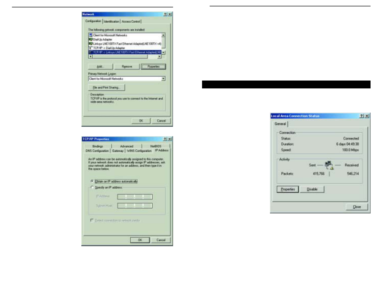
1. Click the Start button, click Settings and open the Control Panel. From
there, double-click the Network icon to open the Network screen.
Overview
Configuring Windows 98 SE and Millennium PCs
• The Power LED will illuminate green as soon as the power adapter is con-
nected.
• The Diag LED will illuminate red for a few seconds while the Router
goes through its internal diagnostic test. The LED will turn off when the
self-test is complete.
5. Power on the cable or DSL modem. Verify that the power is on by checking
the Link LED in the Internet column on the front of the Router. The Link
LED will be illuminated if the power is on and the modem is ready.
6. Press the Reset button on the back of the Router. Hold the button in for three
seconds, or until the Diag LED illuminates red. This restores the Router’s
default settings.
7. Power on your PC.
The Router is now connected.
Continue to the next chapter to configure your PCs.
For Wireless Connections: In addition to accessing the Router through an
Ethernet connection, a wireless connection can be used to access the Router.
After powering on the Router and connecting it to your modem, enter the
Router’s IP Address in the Address field of your wireless PC’s web-browser as
follows: http://192.168.1.1 and press Enter.
Important:
The Router is configured by default to work out of the box
with all Network Everywhere Wireless Adapters. If you have
changed the defaults on your Network Everywhere Wireless
Adapters, or are using other wireless adapters, you must temporar-
ily change your wireless adapter settings to: (SSID = wireless) in
order to initially access the Router wirelessly. After you have
accessed the Router with the default settings, you can change the
Router’s settings to coincide with your Network settings and reset
your adapters.
Important:
Some ISPs—most notably some cable providers—con-
figure their networks so that you do not have to enter a full Internet
address into your web browser or e-mail application to reach your
home page or receive your e-mail. If your Internet home page
address is something very simple, such as “www”, rather than
“www.networkeverywhere.com”, or your e-mail server’s address is
something similar to “e-mail” or “pop3”, rather than “pop.mail.net-
workeverywhere.com”, you won’t be able to properly configure the
Router until you determine the actual Internet addresses of your
Web and e-mail connections.
You must obtain this information prior to connecting the Router to
your network. You can obtain this information by contacting your ISP.
Wireless Cable/DSL Router
Network Everywhere®Series
109
5. Click the OK button again. Windows may ask you for the original
Windows installation disk or additional files. Supply them by pointing to
the correct file location, e.g., D:\win98, D:\win9x,
c:\windows\options\cabs, etc. (This assumes that “D” is the letter of your
CD-ROM drive).
6. If Windows asks you to restart your PC, click the Ye s button. If Windows
does not ask you to restart, restart your computer anyway.
Repeat steps 1-6 for each PC on your network. When all of your PCs are
configured, proceed to Chapter 6: The Router’s Web-based Utility.
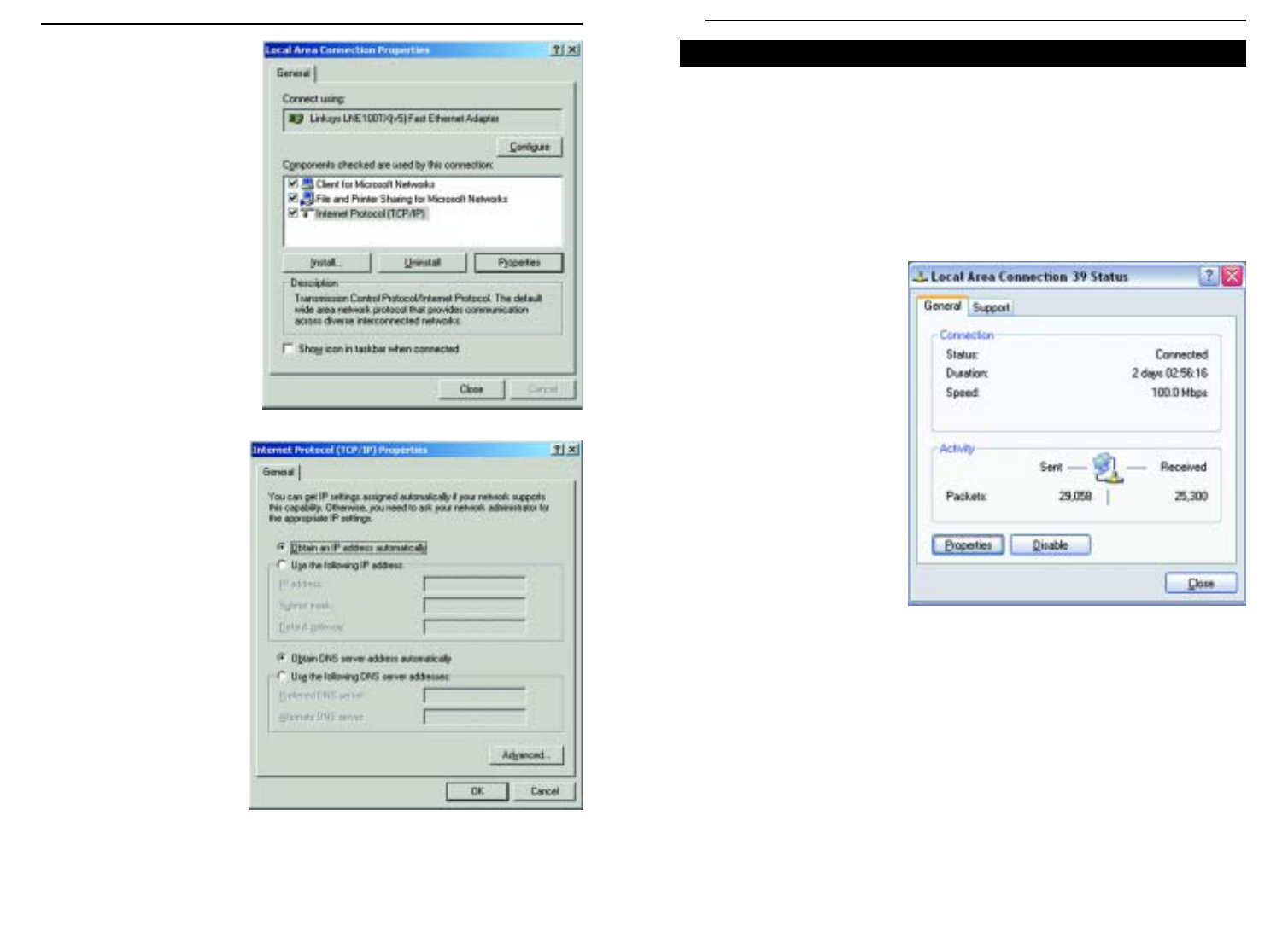
1. Click the Start button, click Settings and open the Control Panel. From
there, double-click the Network and Dial-up Connections icon. This will
display the Network screen.
2. Select the Local Area
Connection icon for the
applicable Ethernet
adapter (usually it is the
first Local Area
Connection listed).
3. When the Local Area Connection Status screen appears, click the
Properties button. (See Figure 4-3.)
Configuring Windows 2000 PCs
Figure 4-3
2. Select the Configuration tab
and highlight the TCP/IP
line for the applicable
Ethernet adapter (as shown
in Figure 4-1). If the word
TCP/IP appears by itself,
select that line. (Note: If
there is no TCP/IP line listed,
refer to your Ethernet
adapter’s documentation to
install TCP/IP now.) Then,
click the Properties button.
3. Click the IP Address tab and
select Obtain an IP address
automatically (as shown in
figure 4-2).
4. Click the Gateway tab and verify that the Installed Gateway field is blank.
Click the OK button.
Figure 4-1
Figure 4-2
Wireless Cable/DSL Router
Network Everywhere®Series
1211
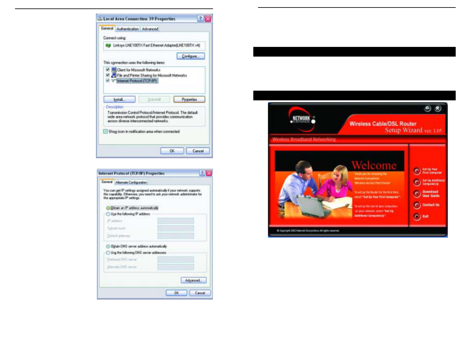
The following instructions assume you are running Windows XP’s default
interface. If you are using the Classic interface (where the icons and menus
look like previous Windows versions), please follow the instructions for
Windows 2000.
1. Click the Start button, open the Control Panel. and click the Network and
Internet Connections icon. Then, click the Network Connections icon to
display the Network screen.
2. Select the Local Area
Connection icon for the
applicable Ethernet
adapter (usually it is the
first Local Area
Connection listed).
3. When the Local Area Connection Status screen appears, click the
Properties button. (See Figure 4-6.)
Configuring Windows XP PCs
Figure 4-6
4. Select Internet Protocol
(TCP/IP) (as shown in
Figure 4-4) and click the
Properties button.
5. Select Obtain an IP
address automatically
and verify that Obtain
DNS server address
automatically is selected
(as shown in Figure 4-5).
Then, click the OK but-
ton and click the OK but-
ton on the subsequent
screens to complete the
PC’s configuration.
Repeat steps 1-5 for each PC on your network. When all of your PCs are
configured, proceed to Chapter 6: The Router’s Web-based Utility.
Figure 4-4
Figure 4-5
Wireless Cable/DSL Router
Network Everywhere®Series
1413
16
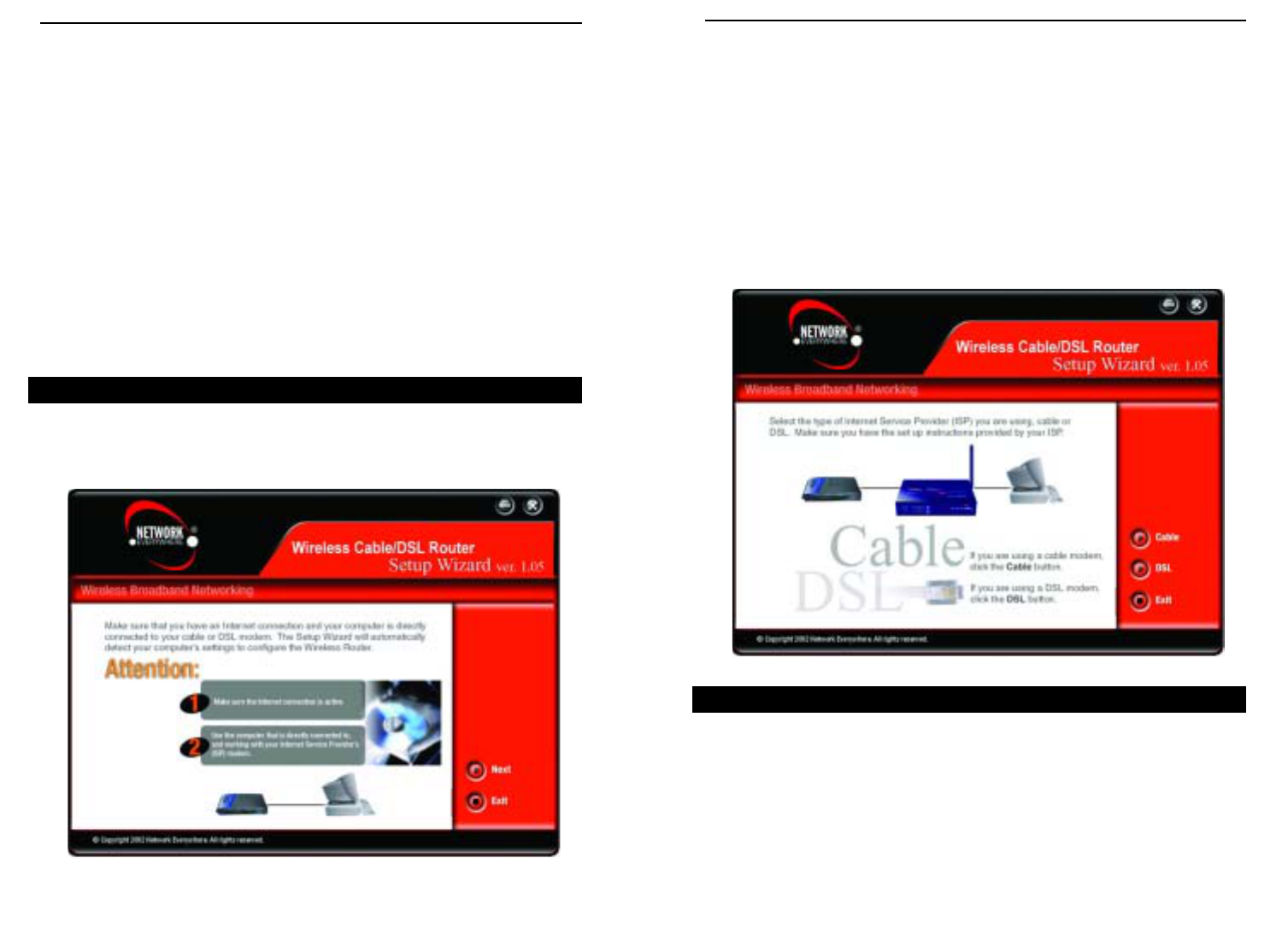
Chapter 5: Using the Setup Wizard
The Network Everywhere Wireless Cable/DSL Router comes with an automat-
ed software installation procedure for Windows 98 SE, Me, 2000, and XP. This
will configure the Router when connecting it for the first time. Thereafter, con-
figuration can be set through the Web Utility.
Insert the Setup Wizard CD into your CD-ROM drive. Unless you have deac-
tivated the auto-run feature of Windows, the screen shown in Figure 5-1 should
appear automatically.
This screen presents you with all of the options provided by the Setup Wizard
CD. These options include:
Set Up Your First Computer This option is used for configuring the Router
for use with your wireless devices.
Before You Start
The Setup Wizard’s Title Screen
Figure 5-1
4. Select Internet Protocol
(TCP/IP) (as shown in
Figure 4-7) and click the
Properties button.
5. Select Obtain an IP
address automatically and
verify that Obtain DNS
server address automati-
cally is selected (as shown
in Figure 4-8). Then, click
the OK button and click the
OK button on the subse-
quent screens to complete
the PC’s configuration.
Repeat steps 1-5 for each PC on your network. When all of your PCs are
configured, proceed to Chapter 6: The Router’s Web-based Utility.
Figure 4-7
Figure 4-8
Wireless Cable/DSL Router
Network Everywhere®Series
15
At this point, you should verify that your Internet connection (Cable or DSL)
is connected to your PC. Verify that your connection is working properly before
clicking the Next button to continue. If you wish to stop the setup process, click
the Exit button.
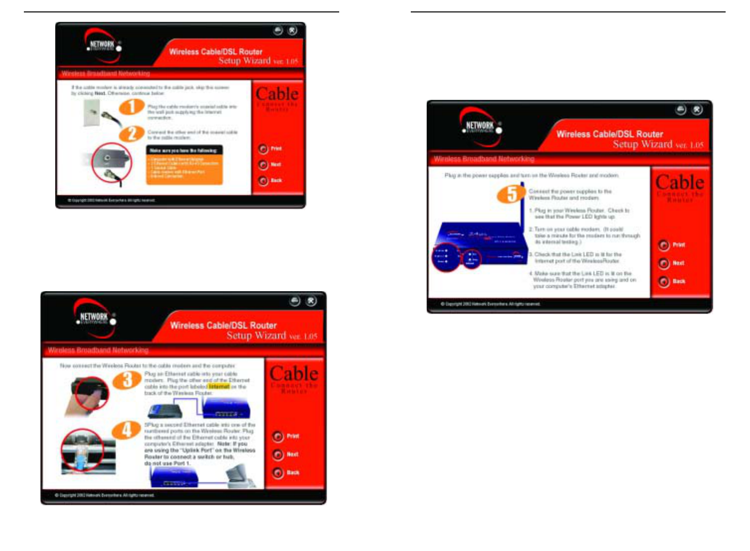
When the screen shown in Figure 5-3 appears, disconnect your PC from your
Internet connection. Then, connect your modem to the Router’s Internet port
and connect your PC to one of the Router’s network ports, numbered 1-4. These
connections should be made with a Category 5 Ethernet Network Cable. Then,
click the Cable button if you’re connected to the Internet through a Cable
Modem or the DSL button if you’re connected to the Internet through a DSL
Modem.
The following screens will specifically address your cable connection. The
screen shown in Figure 5-4 will ask you to verify that your modem is connect-
ed properly. Verify the connection and click the Next button to continue. If you
wish to step back in the setup process, click the Back button. To print this
screen, click the Print button.
Figure 5-3
Set Up Additional Computer(s) This option should only be used to config-
ure DHCP settings on any additional com-
puters. For setting up a computer’s wireless
settings to use with the Router, configure
your wireless devices with the same net-
work settings as the Router.
Download User Guide This User Guide is available on the Setup
Wizard CD, so you won’t need Internet
access to download this. Clicking this but-
ton brought up this User Guide,
Contact Us This option gives you contact information
for Network Everywhere support.
Exit This option closes the Setup Wizard.
The Setup Wizard allows you to configure the Router quickly and easily. This
process begins on the Title Screen, where you should click the Set Up Your
First Computer button. This will bring up the screen shown in Figure 5-2.
Preparing to Set Up
Figure 5-2
Setting Up the Router with a Cable Connection
Wireless Cable/DSL Router
Network Everywhere®Series
1817
Wireless Cable/DSL Router
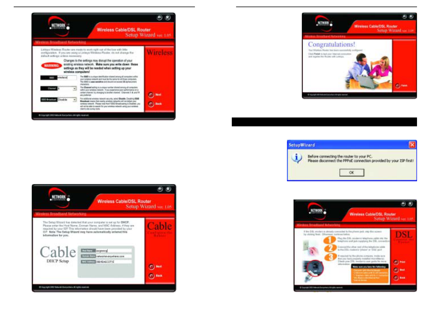
When the screen shown in Figure 5-6 appears, connect the power for the Router
and modem, using a surge protector. Some of the Router’s lights should come
on as shown on the screen. Verify that your connection is working properly
before clicking the Next button to continue. If you wish to step back in the
setup process, click the Back button. To print this screen, click the Print but-
ton.
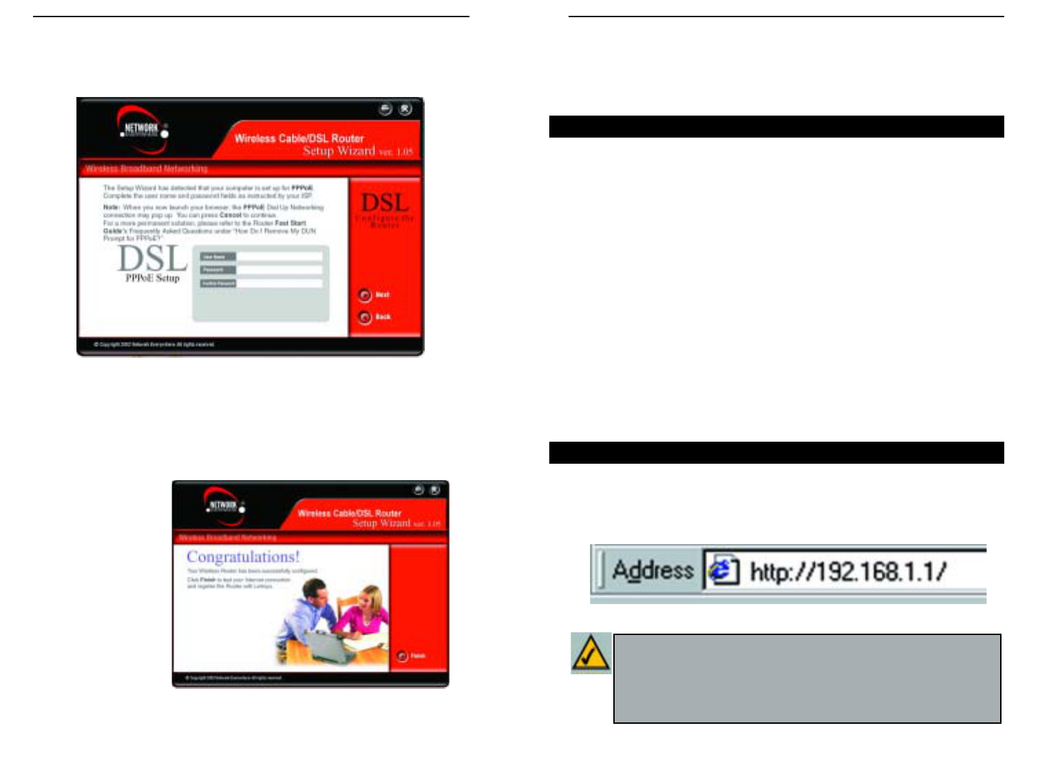
On
the next screen that appears, shown in Figure 5-7, you will configure the
Router’s wireless settings. As this is a wireless router, it can be used with your
wireless devices. However, all settings must be the same for the wireless
devices to be able to communicate with each other. Verify that the following
settings are the same as your other wireless devices:
SSID Think of this as the wireless network’s name. While the
default setting is “wireless”, you should change it to some-
thing unique. It is case sensitive and should not exceed 32
alphanumeric characters.
Channel The preferred settings for this, the channel on which the
wireless signal is broadcast, are 1, 6, and 11.
SSID Broadcast This broadcasts the SSID, allowing access to all nearby wire-
less devices. For increased security, disable this option.
20
Network Everywhere®Series
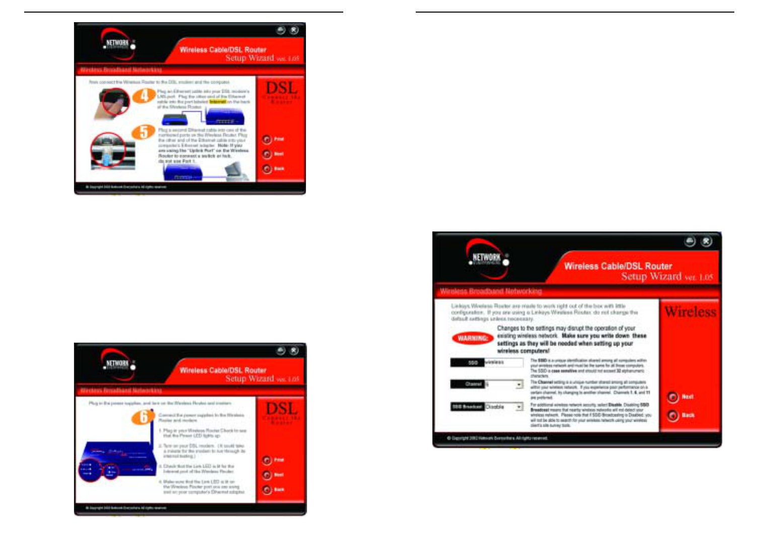
The next screen (Figure 5-5) will ask you to verify that the Router is connect-
ed properly. Connect the Router as shown, without connecting the power or
modem. Click the Next button to continue. If you wish to step back in the setup
process, click the Back button. To print this screen, click the Print button.
19
Figure 5-6
Figure 5-4
Figure 5-5
Wireless Cable/DSL Router
Configuration is complete
and the Router is set up
when you see the final
screen, shown in Figure 5-
9. Click the Finish button
to close the Setup Wizard.
To set up any further com-
puters to connect to the
Router, run the Setup
Wizard again and choose
Set Up Additional
Computer(s). To fine-tune
the Router’s performance,
you can continue to Chapter 6: The Router’s Web-based Utility.
When you first select DSL as your ISP, you will see a warning screen regard-
ing PPPoE (shown
in Figure 5-10). If
you have a PPPoE
connection, follow
these directions. If
your connection is
not PPPoE, disre-
gard these direc-
tions.
The next screen, shown
in Figure 5-11, will ask
you to verify that your
modem is connected
properly. Verify the
connection and click
the Next button to con-
tinue. If you wish to
step back in the setup
process, click the Back
button. To print this
screen, click the Print
button.
22
Network Everywhere®Series
Document and save these settings for future reference and click the Next but-
ton to continue. If you wish to step back in the setup process, click the Back
button.
The following screen will detect your modem’s IP settings and configure the
Router with these settings. (The screen shown in Figure 5-8 is what you would
see if you see if you had a DHCP server.) Click the Next button to continue. If
you wish to step back in the setup process, click the Back button.
21
Figure 5-7
Figure 5-8
Figure 5-9
Setting Up the Router with a DSL Connection
Figure 5-10
Figure 5-11
Wireless Cable/DSL Router
On the next screen that appears, shown in Figure 5-14, you will configure the
Router’s wireless settings. As this is a wireless router, it can be used with your
wireless devices. However, all settings must be the same for the wireless
devices to be able to communicate with each other. Verify that the following
settings are the same as your other wireless devices:
SSID Think of this as the wireless network’s name. While the
default setting is “wireless”, you should change it to some-
thing unique. It is case sensitive and should not exceed 32
alphanumeric characters.
Channel The preferred settings for this, the channel on which the
wireless signal is broadcast, are 1, 6, and 11.
SSID Broadcast This broadcasts the SSID, allowing access to all nearby wire-
less devices. For increased security, disable this option.
Document and save these settings for future reference and click the Next but-
ton to continue. If you wish to step back in the setup process, click the Back
button.
24
Network Everywhere®Series
The next screen (Figure 5-12) will ask you to verify that the Router is connect-
ed properly. Connect the Router as shown, without connecting the power or
modem. Click the Next button to continue. If you wish to step back in the setup
process, click the Back button. To print this screen, click the Print button.
When the screen shown in Figure 5-13 appears, connect the power for the Router
and modem, using a surge protector. Some of the Router’s lights should come
on as shown on the screen. Verify that your connection is working properly
before clicking the Next button to continue. If you wish to step back in the setup
process, click the Back button. To print this screen, click the Print button.
23
Figure 5-12
Figure 5-13
Figure 5-14
Wireless Cable/DSL Router
Chapter 6: The Router’s
Web-based Utility
Use the Router’s web-based utility to administer it. This chapter will describe
each web page in the Utility and each page’s key functions. The utility can be
accessed via your web browser through use of a computer connected to the
Router.
For a basic network setup, most users only have to use the following screens of
the utility:
• Setup Enter the settings provided by your ISP.
• Password The Router’s default password is admin. To secure the Router,
change the Password from its default.
The WEP, Status, DHCP, Log, and Help tabs are also available for basic setup.
For advanced setup, click the Advanced Setup tab to access these screens:
Filters, Forwarding, Dynamic Routing, Static Routing, DMZ Host, MAC Addr
Clone, and Wireless.
To access the web-based utility of the Router, launch Internet Explorer or
Netscape Navigator, and enter the Router’s default IP address, 192.168.1.1, in
the Address field, as shown in Figure 6-1. Then, press Enter.
26
Overview
Logging In
Figure 6-1
Note: If your PC’s Windows operating system supports Universal
Plug and Play (UPnP), Windows will offer to create a desktop short-
cut to the Router. Click the OK button to create the desktop icon, and
then double-click the icon to connect to the Router. Otherwise, con-
nect to the Router manually, as directed in steps 1 and 2.
Network Everywhere®Series
The following screen will detect your modem’s IP settings and configure the
Router with these settings. (The screen shown in Figure 5-15 is what you would
see if you see if you had a PPPoE connection.) Click the Next button to con-
tinue. If you wish to step back in the setup process, click the Back button.
Configuration is complete and the Router is set up when you see the final
screen, shown in Figure 5-16. Click the Finish button to close the Setup
Wizard.
To set up any further computers to connect to the Router, run the Setup Wizard
again and choose Set Up Additional Computer(s). To fine-tune the Router’s
performance, you can
continue to Chapter 6:
The Router’s Web-
based Utility.
25
Figure 5-15
Figure 5-16
Wireless Cable/DSL Router
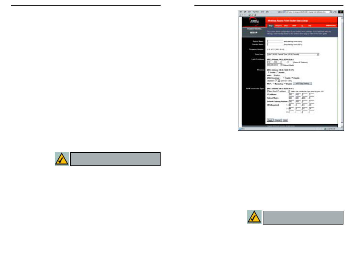
Firmware Version This entry shows the version and date of the firmware the
Router is using. Future versions of the Router’s firmware will be posted and
available for download on the Network Everywhere website at
www.NetworkEverywhere.com.
Time Zone This drop-down menu allows you to set the time zone in which you
are operating the Router.
Device LAN IP Address The values for the Router’s IP Address and Subnet
Mask are shown here. The default values are 192.168.1.1 for the Device IP
Address and 255.255.255.0 for the Subnet Mask.
28
Network Everywhere®Series
27
Figure 6-3
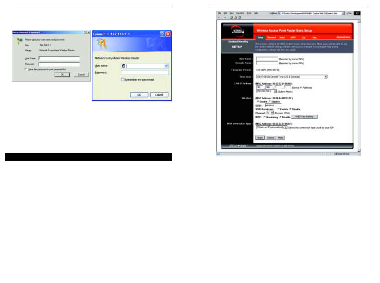
Upon entering the address into the web browser, a password request page will
pop up, as shown in Figure 6-2a. (Windows XP users will see a “Connect to
192.168.1.1” window, shown in Figure 6-2b.)
Leave the User Name field empty, and enter admin (the default password) in
lowercase letters in the Password field. Then, click the OK button.
To apply any of the settings you change on a page of the Utility, click the Apply
button, and then click the Continue button. To cancel any values you’ve
entered on any page of the Utility, click the Cancel button.
The Setup screen, shown in Figure 6-3, is the first screen you see when you
access the web-based utility. If you have already installed and set up the Router,
you have already seen this screen and properly configured all of the screen’s
values. Some options on this screen remain the same while the Internet
Connection option will change depending on how you connect to the Internet.
The main options are described first, with all of the Internet Connection types
following.
Host Name/Domain Name These fields allow you to supply a host and
domain name for the Router. Some ISPs require these names as identification.
You may have to check with your ISP to see if your broadband Internet service
has been configured with a host and domain name. In most cases, leaving these
fields blank will work.
Setup
Figure 6-2a
Figure 6-2b
Wireless Cable/DSL Router
30
Network Everywhere®Series
Wireless (Enable/Disable). In order to utilize the Router’s wireless functions,
select Enable. If you do not wish to utilize any wireless functions, make sure
Disable is selected. (Note: No other wireless functions will be available unless
you enable this setting.)
SSID: The SSID is a unique name for your wireless network. It is case sen-
sitive and must not exceed 32 characters. The default SSID is "wireless "
but you should change this to a personal wireless network name. All wire-
less points in your network must use the same SSID. Verify that you are
using the correct SSID and click the Apply button to set it.
SSID Broadcast - Allows the SSID to be broadcast on your network. You
may want to enable this function while configuring the Router, but make
sure that you disable it when you are finished. With this enabled, someone
could easily obtain the SSID information with site survey software and gain
unauthorized access to your network. Click Enable to broadcast. Click
Disable to increase network security and prevent the SSID from being seen
on networked PCs.
Channel Select the appropriate channel from the list provided to corre-
spond with your network settings, between 1 and 11. All points in your
wireless network must use the same channel in order to function correctly.
Verify that the correct channel is selected and click the Apply button to set
it.
WEP (Mandatory/Disable). In order to utilize WEP encryption, select
Enable. If you do not wish to utilize WEP encryption, make sure Disable
is selected.
Internet Connection The Router supports three connection types: DHCP,
PPPoE, and Static IP. Each Setup screen and available features will differ
depending on what kind of connection type you select.
Obtain an IP Address Automatically
By default, the Router’s Internet Connection is set to Obtain an IP auto-
matically, as shown in Figure 6-3, and it should be used only if your ISP
supports DHCP.
To apply any of the settings you’ve changed on this page, click the Apply
button, and then click the Continue button. To cancel any values you’ve
entered on this page, click the Cancel button. If you should need any fur-
ther information about anything on this screen, click the Help button.
29
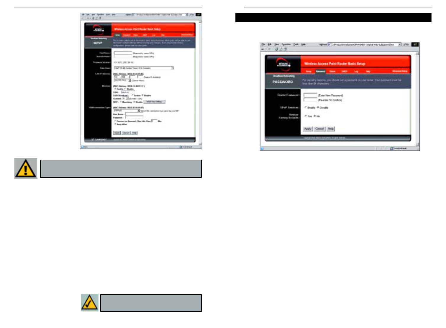
Static IP
If you are required
to use a permanent
IP address, then
select Static
(Fixed) IP
address, shown in
Figure 6-4.
IP Address This is the Router’s IP address, when seen from the Internet, or
the Internet. Your ISP will provide you with the IP Address you need to spec-
ify here.
Subnet Mask This is the Router’s Subnet Mask, as seen by external users on
the Internet (including your ISP). Your ISP will provide you with the Subnet
Mask.
Default Gateway Address Your ISP will provide you with the Default
Gateway Address, which is the ISP’s IP address.
DNS (Required) Your ISP will provide you with at least one DNS (Domain
Name System) Server IP
Address.
To apply any of the settings you’ve changed on this page, click the Apply but-
ton, and then click the Continue button. To cancel any values you’ve entered
on this page, click the Cancel button. If you should need any further infor-
mation about anything on this screen, click the Help button.
Figure 6-4
Note: Successfully connection to the
Internet means these settings are correct.
Note: To configure WEP encryption, see
Appendix C: Configuring Wireless Security.
Wireless Cable/DSL Router
32
Network Everywhere®Series
31
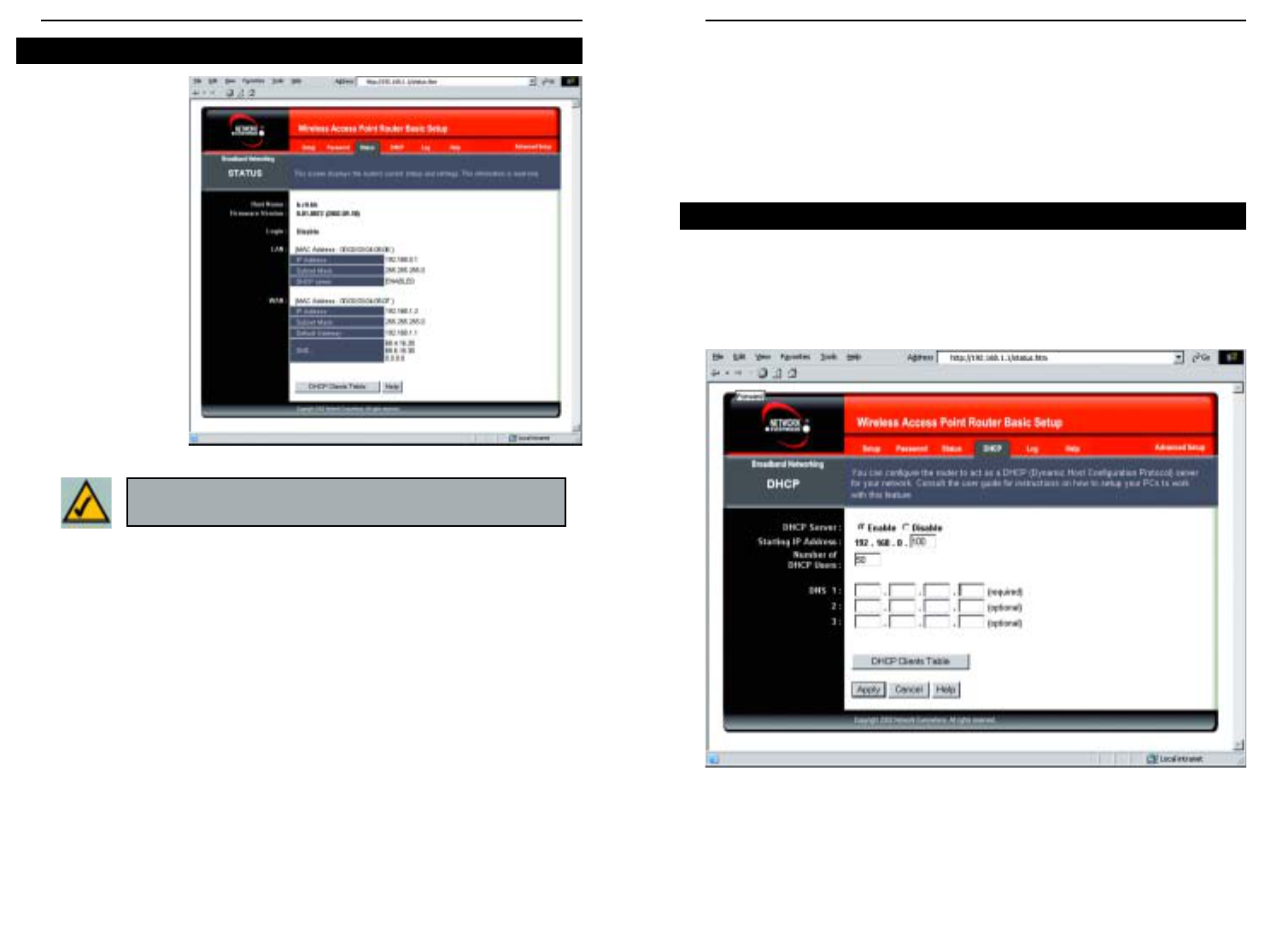
The Password screen, shown in Figure 6-6, allows you to set up a password and
UPnP Services. You can also restore default settings on the Router.
Router Password Set a password for the Router. You can use up to 64 alphanu-
meric characters. The default password is admin. If you don’t change the pass-
word, all users on your network will be able to access the Router using the
default password. For greater security, you should change the password from its
default setting.
UPnP Services Universal Plug and Play (UPnP) allows Windows XP to auto-
matically configure the Router for various Internet applications, such as gam-
ing and videoconferencing. Click the radio button next to Enable to enable
UPnP Services, or Disable to disable UPnP Services.
Restore Factory Defaults If you select the Restore Factory Defaults option
and click the Apply button, you will clear all of the Router’s settings. Do not
restore the factory defaults unless you are having difficulties with the Router
and have exhausted all other troubleshooting measures. Once the Router is
reset, you will have to re-enter all of your configuration data.
To apply any of the settings you’ve changed on this page, click the Apply but-
ton, and then click the Continue button. To cancel any values you’ve entered
on this page, click the Cancel button. If you should need any further informa-
tion about anything on this screen, click the Help button.
Figure 6-6
Password
PPPoE
Some DSL-based ISPs
use PPPoE (Point-to-
Point Protocol over
Ethernet) to establish
Internet connections.
If you are connected to
the Internet through a
DSL line, check with
your ISP to see if they
use PPPoE. If they do,
you will have to enable
PPPoE, shown in
Figure 6-5.
User Name and
Password Enter the
User Name and
Password provided by
your ISP.
Connect on Demand: Max Idle Time You can configure the Router to cut
the connection with your ISP after a specified period of time (Max Idle
Time). If you have been disconnected due to inactivity, Connect on Demand
enables the Router to automatically re-establish your connection as soon as
you attempt to access the Internet again. If you wish to activate Connect on
Demand, click the radio button. In the Max Idle Time field, enter the num-
ber of minutes you want to have elapsed before your Internet access dis-
connects.
Keep Alive Option: Redial Period If you select this option, the Router will
periodically check your Internet connection. If you are disconnected, then
the Router will automatically re-establish your connection. To use this
option, click the radio button next to Keep Alive. In the Redial Period field,
enter the number of seconds you want the Redial Period to last. The default
Redial Period is 30 seconds.
To apply any of the settings you’ve changed on this page, click the Apply but-
ton, and then click the Continue button. To cancel any values you’ve entered
on this page, click the Cancel button. If you should need any further infor-
mation about anything
on this screen, click the
Help button.
Figure 6-5
Important: If you enable PPPoE, remember to remove any
PPPoE applications that are already installed on any of your PCs.
Note: Successfully connection to the
Internet means these settings are correct.
Wireless Cable/DSL Router
34
Network Everywhere®Series
33
WA N These fields display the Router’s current MAC Address, IP Address,
Subnet Mask, and Default Gateway IP Address, as seen by external users on the
Internet. The DNS (Domain Name System) IP Address fields show the IP
address(es) of the DNS server(s) currently used by the Router. Multiple DNS
IP settings are common. In most cases, the first available DNS entry is used.
DHCP Clients Table Click the DHCP Clients Table button to view the list of
PCs that were given IP addresses by the Router.
DHCP
From the DHCP screen, shown in Figure 6-8, you can configure the settings to
your DHCP server. A Dynamic Host Configuration Protocol (DHCP) server
automatically assigns an IP address to each PC on your network for you. Unless
you already have one, it is highly recommended that you leave the Router
enabled as a DHCP server.
DHCP Server DHCP is already enabled by factory default. If you already
have a DHCP server on your network, set the Router’s DHCP option to
Disable. Click the Apply button and then the Continue button. If you disable
DHCP, remember to assign a static IP address to the Router.
DHCP
Figure 6-8
The Status screen,
shown in Figure 6-7
displays the Router’s
current status; it
reflects the data and
selections you’ve
entered using the
Setup screen.
All of the informa-
tion provided on this
screen is read-only.
To make changes,
select the Setup tab.
Host Name This field shows the Router’s name.
Firmware Version This field shows the installed version and date of the
firmware.
Login This indicates if you are using a dial-up style connection, e.g., PPPoE.
For PPPoE only, there is a Connect button to click if you are disconnected and
want to re-establish a connection.
LAN These fields display the Router’s current MAC Address, IP Address, and
Subnet Mask, as seen by users on your local area network. The DHCP Server
field shows the status of the Router’s DHCP server function, which is either
enabled or disabled.
Status
Figure 6-7
Note: The information provided and buttons available will vary
depending on the Router’s settings.
Wireless Cable/DSL Router
36
Network Everywhere®Series
35
If you should need any further information about anything on this screen, click
the Help button.
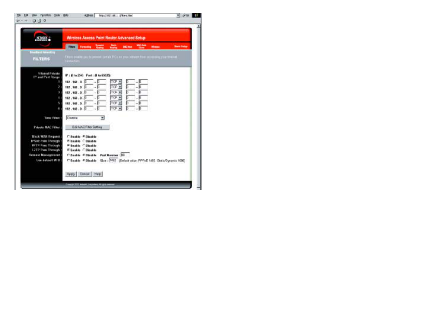
Under the Help tab, shown in Figure 6-10, you’ll find links to all of the utili-
ty’s internal support documentation along the left margin, including the fol-
lowing:
Network Everywhere Website Clicking this link will take you to Network
Everywhere’s website, www.NetworkEverywhere.com, provided you are con-
nected to the Internet.
Figure 6-9
Help
Figure 6-10
Starting IP Address Enter a value for the DHCP server to start with when
issuing IP addresses. This value must be 192.168.1.2 or greater, because the
Router’s default IP address is 192.168.1.1.
Number of DHCP Users (Optional) Enter the maximum number of PCs for
the DHCP server to assign IP addresses. This number cannot be greater than
253.
DNS The Domain Name System (DNS) is how the Internet translates domain
or website names into Internet addresses or URLs. Your ISP will provide you
with at least one DNS Server IP Address. If you wish to use another, type that
IP Address in one of these fields. You can type up to three DNS Server IP
Addresses here. The Router will use these for quicker access to functioning
DNS servers.
DHCP Clients Table Click the DHCP Clients Table button to show the cur-
rent DHCP Client data. (This data is stored in temporary memory and changes
periodically.)
To apply any of the settings you’ve changed on this page, click the Apply but-
ton, and then click the Continue button. To cancel any values you’ve entered
on this page, click the Cancel button. If you should need any further informa-
tion about anything on this screen, click the Help button.
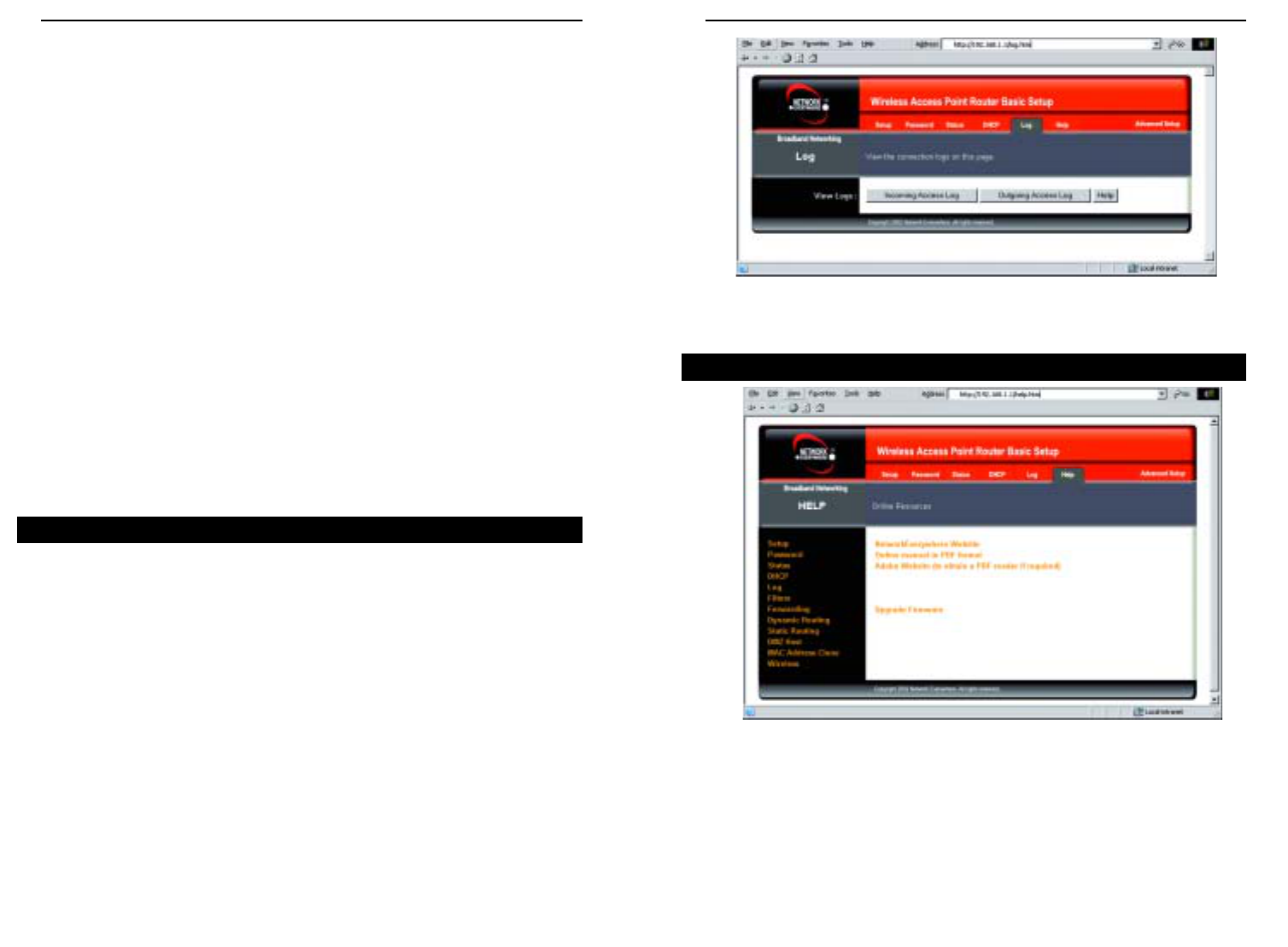
The Log tab, shown in Figure 6-9, provides you with a log of all incoming and
outgoing URLs or IP addresses for your Internet connection.
Access Log To access activity logs, select the Enable option next to Access
Log. This function can be disabled by clicking the Disable radio button.
Temporary logs can be accessed from the Log screen by clicking either the
Incoming Access Log or Outgoing Access Log button. The Incoming Access
Log gives you a log of all the incoming Internet traffic while the Outgoing
Access Log lists all the URLs and IP addresses of Internet sites that users on
your network have accessed.
Log

Wireless Cable/DSL Router
•Dynamic Routing - Sets up the Router so it will automatically adjust to phys-
ical changes in the network’s layout.
•Static Routing - Sets up static routes needed when network information must
travel to a specific host or network.
•DMZ Host - Allows one local user to be exposed to the Internet for use of spe-
cial-purpose services such as online gaming or videoconferencing.
•MAC Address Cloning - Allows you to “clone” your Ethernet adapter’s MAC
address onto the Router.
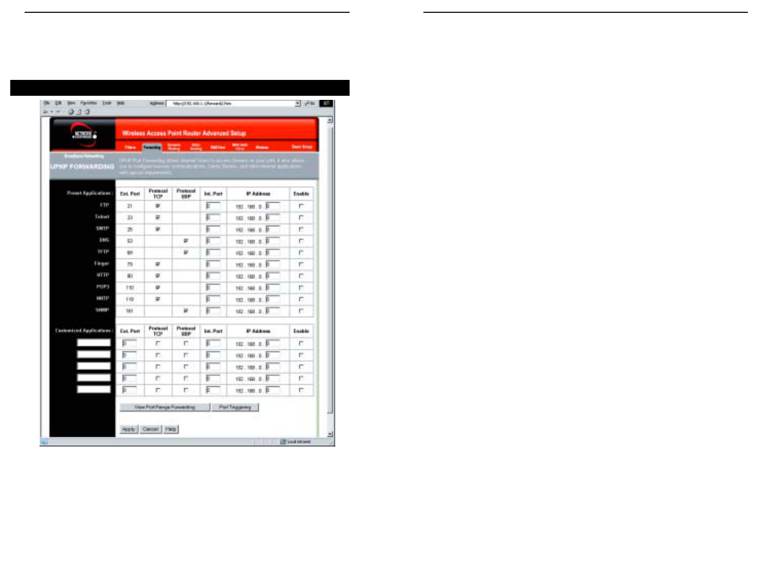
From the IP filters screen, shown in Figure 6-11, you can block specific inter-
nal users from accessing the Internet and enable Virtual Private Network (VPN)
sessions. You can set up filters by using IP addresses or network port numbers
(or a range of ports).
Filtered Private IP Range To set up a filter using IP addresses, enter the range
of IP addresses you wish to filter in the IP address fields. Users with filtered
IP addresses will not be able to access the Internet at all. If you only want to
filter one IP address instead of a range of IP addresses, enter the same value
into both fields. For instance, if you wish to filter the PC with the IP address
of 192.168.1.5, enter 5into both fields on one line: 192.168.1.5~ 192.168.1.5.
Click the Apply button when finished.
Filtered Private Port Range To filter users by network port number, enter a
network port number or a range of network ports. Select the protocol for each
port number you want to filter, TCP or UDP. Enter the port numbers you want
to filter in the port numbers fields. Users connected to the Router will no
longer be able to access any port number listed there. Click the Apply button
when you’re done.
Time Filter This feature allows you to block access to the Internet during pre-
set times.
38
Network Everywhere®Series
37
IP Filtering
Online manual in PDF format and Adobe Website Clicking the Online man-
ual in PDF format link will take you to the latest version of the user guide for
this Router. The guide will be in Adobe Acrobat Portable Document File (.pdf)
format. You will need the Adobe Acrobat Reader to view this pdf. If you do not
have the Acrobat Reader, click the Adobe Website link to download it. These
links work only if you are connected to the Internet.
Upgrade Firmware New firmware versions are posted at
www.NetworkEverywhere.com and can be downloaded for free. If the Router
can access the Internet already, there’s no need to download a newer firmware
version, unless that version has a new feature that you want to use. (To learn
about any new firmware with new features, visit
www.NetworkEverywhere.com.) Loading new firmware onto the Router does
not always enhance the speed or the quality of your connection.
To upgrade the Router’s firmware:
1. Download the firmware upgrade file from www.NetworkEverywhere.com,
and extract the file using archive software such as WinZip.
2. Select the Help tab (see Figure 6-10).
3. Click Upgrade Firmware to display a new window.
4. Click the Browse button to find the firmware upgrade file you extracted.
5. Double-click the firmware file you extracted. Click the Upgrade button
and follow the on-screen instructions.
The following instructions are for advanced users or users whose setup require
special configuration. When you click the Advanced tab, you will be able to set
up these features. There are six additional tabs available.
•Filters - Filters block specific internal users from Internet access and enable
Virtual Private Network (VPN) sessions.
•Forwarding - Sets up public services on your network.
Note: By upgrading the Router’s firmware, you may lose the Router’s
configuration settings.
Advanced
Wireless Cable/DSL Router
40
Network Everywhere®Series
39
Block WAN Requests By enabling the Block WAN Request feature, you can
prevent your network from being “pinged,” or detected, by other Internet
users. The Block WAN Request feature also reinforces your network security
by hiding your network ports. Both functions of the Block WAN Request fea-
ture make it more difficult for outside users to work their way into your net-
work. This feature is enabled by default.
IPSec Pass Through This feature lets you use IPSec Pass Through. IPSec
Pass Through is enabled by default.
To disable IPSec Pass Through, click on Disable.
PPTP Pass Through Point-to-Point Tunneling Protocol is the method used to
enable VPN sessions. PPTP Pass Through is enabled by default.
To disable this feature, click on Disable next to PPTP Pass Through.
L2TP Pass Through This feature lets you use L2TP Pass Through. L2TP Pass
Through is enabled by default.
To disable this feature, click on Disable next to L2TP Pass Through.
Remote Management This feature allows you to manage the Router from a
remote location, via the Internet. To enable this feature, click on Enable, and
enter the desired port number (default is 8080). Click the Apply button and
then the Continue button. Remote Management must be activated before you
can manage the Router from a remote location. If you wish to use this feature
on the browser, enter http:\\<WAN IP Address>:8080. (Enter your specific
Internet IP Address in place of <WAN IP Address>.) Remote Management
involves an inherent security risk and should not be enabled without first
changing the Password (from the Setup screen) from its default settings.
To disable this feature, click on Disable.
MTU (Maximum Transmission Unit) This feature specifies the largest pack-
et size permitted for network transmission. Select Enable and enter the value
desired. You should leave this value in the 1200 to 1500 range. Most DSL
users should use the value 1492. For static and dynamic connections, the
default MTU value is set at 1500 when disabled. For PPPoE connections, the
default MTU value is set at 1492 when disabled.
Private MAC Filter This feature filters the Ethernet adapter’s specific MAC
address from going out to the Internet.
To check your Ethernet adapter’s MAC address, run winipcfg or ipconfig in
the command prompt, depending on which Windows operating system you are
using. To set the MAC filter, click the Edit MAC Filter Setting button. When
a second window appears (see Figure 6-14), select the range in the drop-down
box, and at the MAC number prompt, enter the 12-digit MAC address you want
to filter. Click the Apply button and the Continue button, before closing the
window. For information on obtaining a MAC address, go to “Appendix D:
Finding the MAC Address and IP Address for Your Ethernet Adapter.”
Figure 6-11
Wireless Cable/DSL Router
42
Network Everywhere®Series
41
The Preset Applications at the top of the list are among the most widely used
Internet applications. They include the following:
•FTP (File Transfer Protocol) A protocol used to transfer files over a
TCP/IP network (Internet, UNIX, etc.). For example, after developing the
HTML pages for a website on a local machine, web developers typically
upload the files to the web server using FTP. FTP includes functions to log
onto the network, list directories, and copy files. FTP operations can be per-
formed by typing commands at a command prompt or via an FTP utility
running under a graphical interface such as Windows. FTP transfers can
also be initiated from within a web browser by entering the URL preceded
by ftp://.
•Telnet A terminal emulation protocol commonly used on Internet and
TCP/IP-based networks. It allows a user at a terminal or computer to log
onto a remote device and run a program.
•SMTP (Simple Mail Transfer Protocol) The standard e-mail protocol on
the Internet. It is a TCP/IP protocol that defines the message format and the
message transfer agent (MTA), which stores and forwards the mail.
•DNS (Domain Name System) The way that Internet domain names are
located and translated into IP addresses. A domain name is a meaningful
and easy-to-remember “handle” for an Internet address.
•TFTP (Trivial File Transfer Protocol) A version of the TCP/IP FTP proto-
col that has no directory or password capability.
•Finger A UNIX command widely used on the Internet to find out infor-
mation about a particular user, such as his or her telephone number, whether
the user is currently logged on, and the last time the user was logged on. The
person being “fingered” must have placed his or her profile on the system
in order for the information to be available. Fingering requires entering the
full user@domain address, for example, name@universityname.edu.
•HTTP (HyperText Transport Protocol) The communications protocol used
to connect to servers on the World Wide Web. Its primary function is to
establish a connection with a web server and transmit HTML pages to the
client web browser.
•POP3 (Post Office Protocol 3) A standard mail server commonly used on
the Internet. It provides a message store that holds incoming e-mail until
users log on and download it. POP3 is a simple system with little selectivi-
ty. All pending messages and attachments are downloaded at the same time.
POP3 uses the SMTP messaging protocol. (SMTP may also need to be for-
warded.)
To apply any of the settings you’ve changed on this page, click the Apply but-
ton, and then click the Continue button. To cancel any values you’ve entered
on this page, click the Cancel button. If you should need any further informa-
tion about anything on this screen, click the Help button.
UPnP Forwarding
Clicking the Forwarding tab will access the UPnP Forwarding screen, shown in
Figure 6-12. This screen displays preset application settings as well as options
for customization of port services for other applications.
Forwarding
Figure 6-12
Wireless Cable/DSL Router
44
Network Everywhere®Series
43
To apply any of the settings you’ve changed on this page, click the Apply but-
ton, and then click the Continue button. To cancel any values you’ve entered
on this page, click the Cancel button. If you should need any further informa-
tion about anything on this screen, click the Help button.
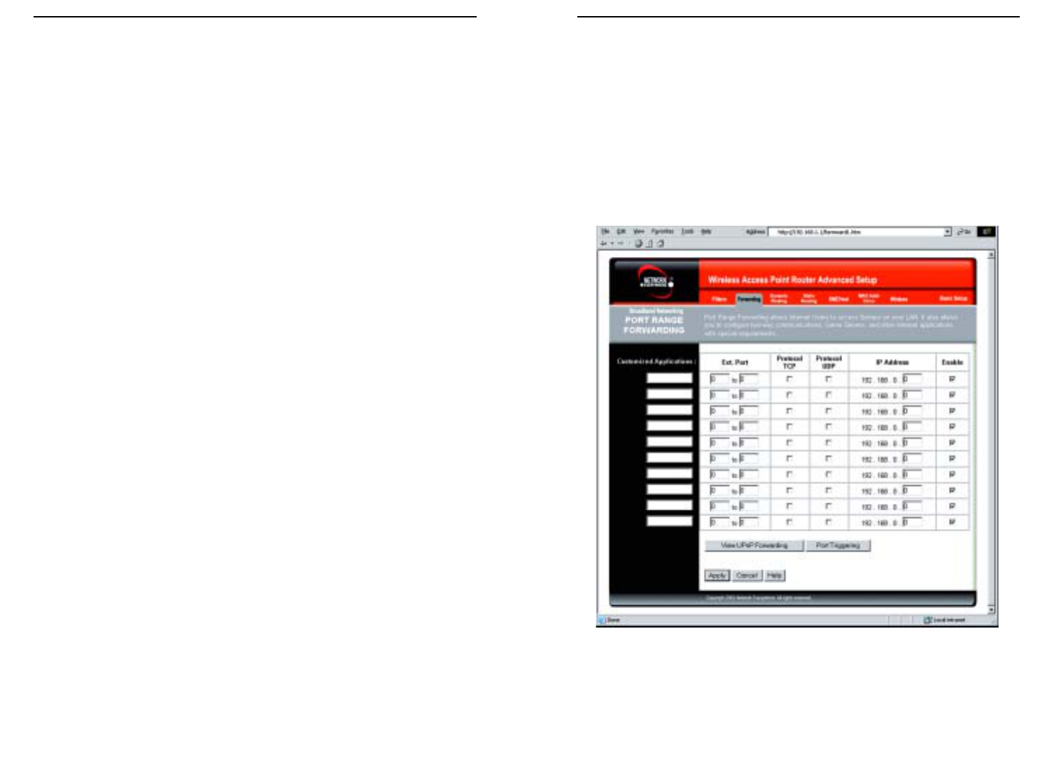
Port Range Forwarding
Click the View Port Range Forwarding button will access the Port Range
Forwarding screen, shown in Figure 6-13. To return to the UPnP Forwarding
screen, click the View UPnP Forwarding button.
Figure 6-13
•NNTP (Network News Transfer Protocol) The protocol used to connect to
Usenet groups on the Internet.
•SNMP (Simple Network Management Protocol) A widely used network
monitoring and control protocol. Data is passed from SNMP agents, which
are hardware and/or software processes reporting activity in each network
device (switch, router, bridge, etc.) to the workstation console used to over-
see the network. The agents return information contained in a MIB
(Management Information Base), which is a data structure that defines
what is obtainable from the device and what can be controlled (turned off,
on, etc.).
Enter the number of the internal port used by the server in the Int. Port col-
umn. Check with the Internet application software documentation for more
information.
Enter the IP address of the server that you want the Internet users to be able to
access. For information about finding the IP address, go to “Appendix D:
Finding the MAC Address and IP Address for Your Ethernet Adapter.”
You must check the Enable box to enable the applications you have defined.
To add a Customized Application using UPnP Forwarding:
1. Enter the name of the application in the appropriate Customized
Application field.
2. Next to the name of the application, enter the number of the external port
used by the server in the Ext. Port column. Check with the Internet appli-
cation software documentation for more information.
3. On the same line, select Protocol TCP or Protocol UDP.
4. Enter the number of the internal port used by the server in the Int. Port col-
umn. Check with the Internet application software documentation for more
information.
5. Enter the IP address of the server that you want the Internet users to be able
to access. For information about finding the IP address, go to “Appendix D:
Finding the MAC Address and IP Address for Your Ethernet Adapter.”
6. Check the Enable box to enable the services you have defined. UPnP
Forwarding will not function if the Enable button is left unchecked. This is
disabled (unchecked) by default.
Wireless Cable/DSL Router
46
Network Everywhere®Series
45
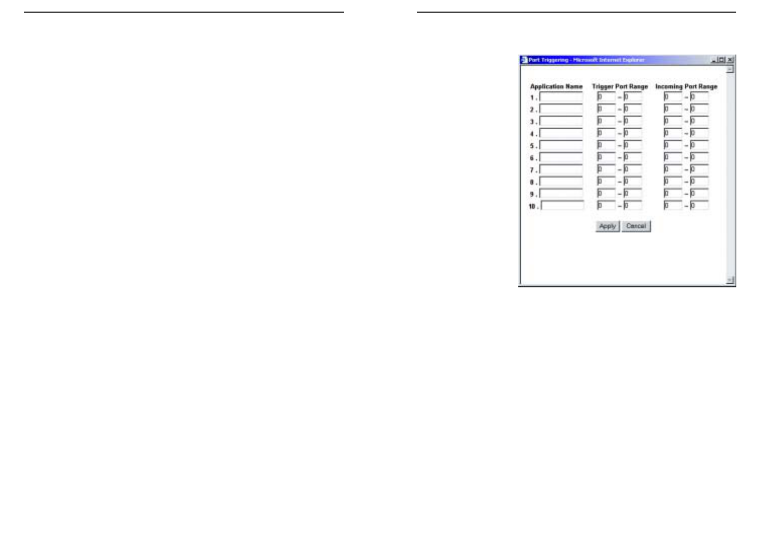
Port Triggering
From the Port Range
Forwarding or UPnP
Forwarding screens,
click the Port
Triggering button to
access the Port
Triggering screen,
shown in Figure 6-14.
This allows the Router
to watch outgoing data
for specific port num-
bers. The IP address of
the computer that sends
the matching data is
remembered by the
Router, so that when
the requested data
returns through the
Router, the data is
pulled back to the prop-
er computer by way of
IP address and port
mapping rules.
1. Enter the Application Name of the trigger.
2. Enter the Trigger Port Range used by the application. Check with the
Internet application for the port number needed.
3. Enter the Incoming Port Range used by the application. Check with the
Internet application for the port number needed.
4. Click the Apply button and then click the Continue button. Click the
Cancel button to cancel any values you’ve entered.
Figure 6-14
Port Range Forwarding sets up public services on your network, such as web
servers, ftp servers, e-mail servers, or other specialized Internet applications.
(Specialized Internet applications are any applications that use Internet access
to perform functions such as videoconferencing or online gaming. Some
Internet applications may not require any forwarding.) When users send this
type of request to your network via the Internet, the Router will forward those
requests to the appropriate PC. Before using Forwarding, the Router’s DHCP
function must be disabled under the DHCP tab and the Router must be assigned
a new static LAN IP address because the IP address may change when using
the DHCP server.
If you need to forward all ports to one PC, see the “DMZ” section.
To add a Customized Application using Port Range Forwarding:
1. Enter the name of the application in the appropriate Customized
Application field.
2. Next to the name of the application, enter the number of the external port
used by the server in the Ext. Port column. Check with the Internet appli-
cation software documentation for more information.
3. On the same line, select Protocol TCP or Protocol UDP.
4. Enter the IP address of the server that you want the Internet users to be able
to access. For information about finding the IP address, go to “Appendix D:
Finding the MAC Address and IP Address for Your Ethernet Adapter.”
5. Check the Enable box to enable the services you have defined. Port Range
Forwarding will not function if the Enable button is left unchecked. This is
disabled (unchecked) by default.
6. Configure as many entries as needed—the Router supports up to 10 ranges
of ports. Click the Apply button and then the Continue button when you
are done.
To apply any of the settings you’ve changed on this page, click the Apply but-
ton, and then click the Continue button. To cancel any values you’ve entered
on this page, click the Cancel button. If you should need any further informa-
tion about anything on this screen, click the Help button.
Wireless Cable/DSL Router
48
Network Everywhere®Series
47
To apply any of the settings you’ve changed on this page, click the Apply but-
ton, and then click the Continue button. To cancel any values you’ve entered
on this page, click the Cancel button. If you should need any further informa-
tion about anything on this screen, click the Help button.
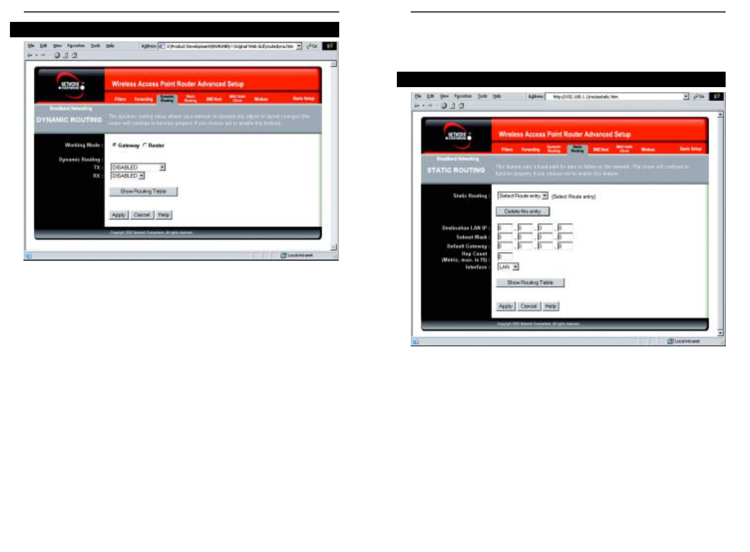
If the Router is connected to more than one network, it may be necessary to set
up a static route between them. This can be accomplished from the Static
Routing screen, shown in Figure 6-16. A static route is a pre-determined path-
way that network information must travel to reach a specific host or network.
From the Static Routing tab, click the Show Routing Table button to view the
current static routing configuration.
To create a static route entry:
1. Select a Static Route Entry from the drop-down list. The Router supports
up to 20 static route entries.
Static Routing
Figure 6-16
From the Dynamic Routing screen, shown in Figure 6-15, you can enable the
Router to automatically adjust to physical changes in the network’s layout. The
Router, using the RIP protocol, determines the network packets’ route based on
the fewest number of hops between the source and the destination. The RIP pro-
tocol regularly broadcasts routing information to other routers on the network.
To set up Dynamic Routing:
1. Choose the correct Working Mode.Gateway Mode should be used if the
Router is hosting your network’s connection to the Internet. Router Mode
should be selected if the Router exists on a network with other routers. In
Router Mode, any computer connected to the Router will not be able to con-
nect to the Internet unless you have another router functioning in the
Gateway mode.
2. Choose a Dynamic Routing path protocol for either transmission (TX:) or
reception (RX:) of network data by selecting Enabled.
Click the Show Routing Table button to open a chart displaying how data is
routed through your LAN.
Dynamic Routing
Figure 6-15
Wireless Cable/DSL Router
50
Network Everywhere®Series
49
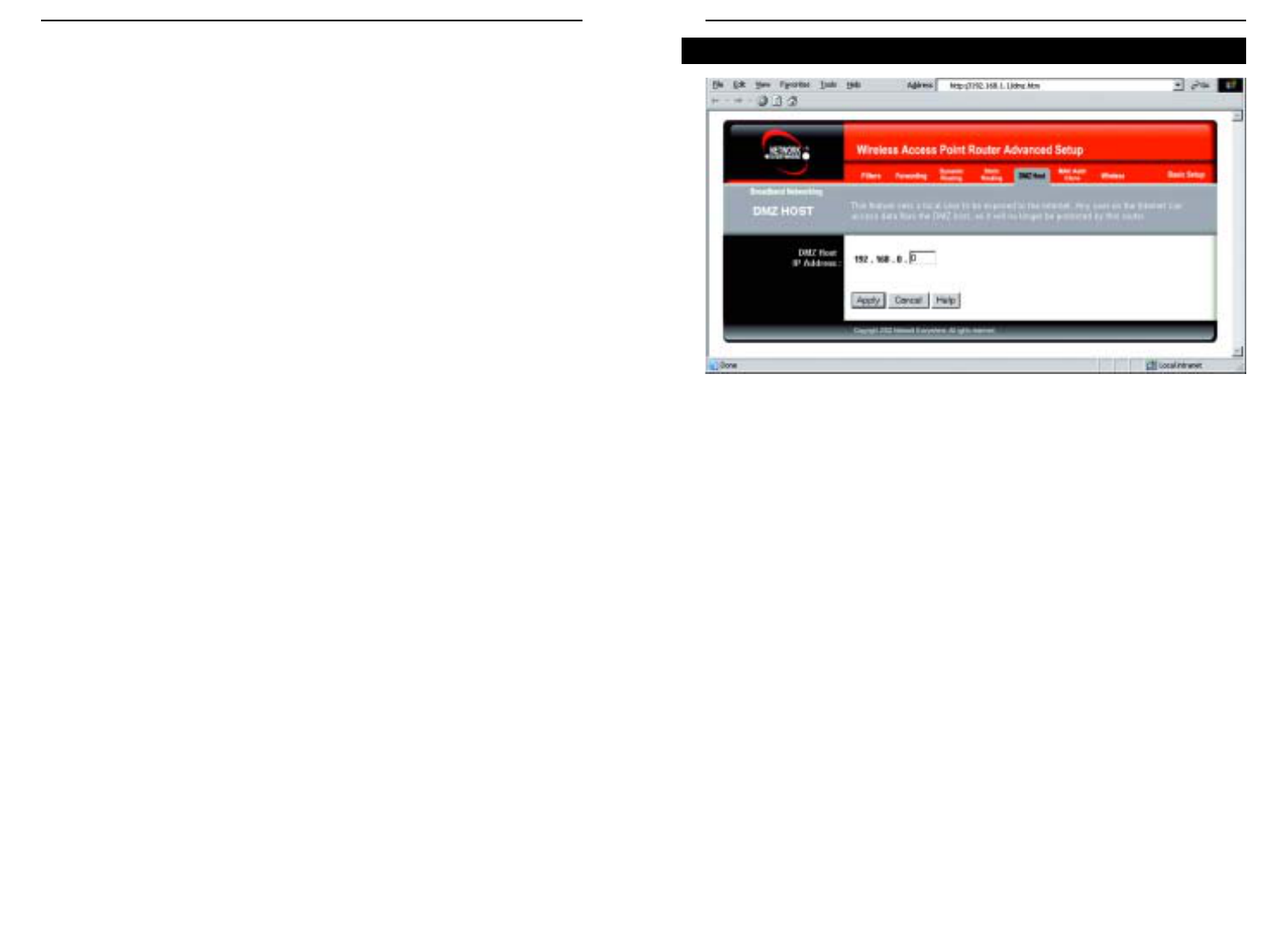
From the DMZ Host screen, shown in Figure 6-17, you can expose one local
user to the Internet for a special-purpose service such as Internet gaming and
videoconferencing.
Port Range Forwarding forwards a maximum of 10 ranges of ports, and DMZ
Hosting forwards all the ports for one PC at the same time. DMZ Hosting is
less secure.
•To expose one PC, enter the computer’s IP address. For more information
about finding a computer’s IP address, refer to “Appendix D: Finding the
MAC Address and IP Address for Your Ethernet Adapter.”
•Deactivate DMZ by entering 0in the field. (This is the default setting.)
To apply any of the settings you’ve changed on this page, click the Apply but-
ton, and then click the Continue button. To cancel any values you’ve entered
on this page, click the Cancel button. If you should need any further informa-
tion about anything on this screen, click the Help button.
DMZ Host
Figure 6-17
To delete a Static Routing entry, select an entry, and click the Delete this
entry button.
2. Enter the following data to create a new static route.
Destination LAN IP: The Destination LAN IP is the address of the remote
network or host to which you want to assign a static route. Enter the IP
address of the host for which you wish to create a static route here. If you
are building a route to an entire network, be sure that the network portion
of the IP address is set to 0. For example, the Router’s standard IP address
is 192.168.1.1. Based on this address, the address of the routed network is
192.168.1.x, with the last digit “x” determining the Router’s place on the
network. Therefore you would enter the IP address 192.168.1.0 if you want-
ed to route to the Router’s entire network, rather than just to the Router.
Subnet Mask: The Subnet Mask determines which portion of an IP
address is the network portion, and which portion is the host portion. Take,
for example, a network in which the Subnet Mask is 255.255.255.0. This
determines (by using the values 255) that the first three numbers of a net-
work IP address identify this particular network, while the last digit (from
1 to 254) identifies the specific host.
Default Gateway: This IP address should be the IP address of the gateway
device that allows for contact between the Router and the remote network
or host.
Hop Count: This determines the maximum number of steps between net-
work nodes that data packets will travel. A node is any device on the net-
work, such as PCs, print servers, routers, etc. The maximum metric, or
measure, of hops is 15.
Interface: Select LAN or WA N , depending on the location of the static
route’s final destination.
To apply any of the settings you’ve changed on this page, click the Apply but-
ton, and then click the Continue button. To cancel any values you’ve entered
on this page, click the Cancel button. If you should need any further informa-
tion about anything on this screen, click the Help button.
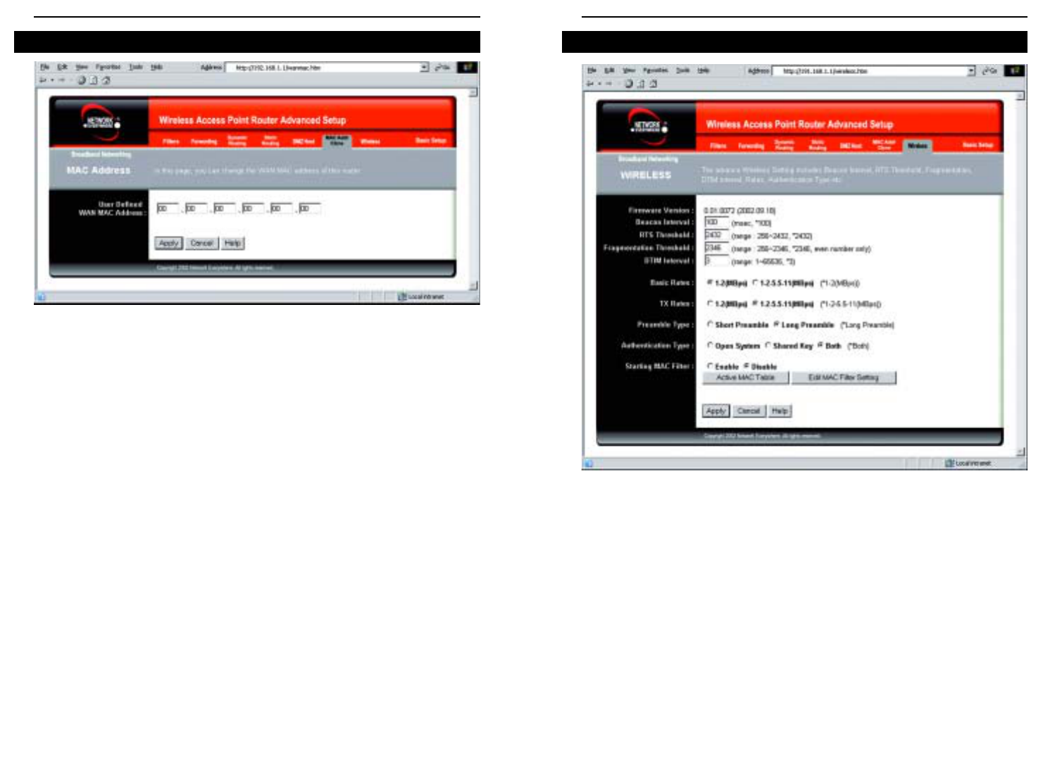
Wireless Cable/DSL Router
52
Network Everywhere®Series
51
Before making any changes to the Wireless tab, shown in Figure 6-19, please
check the wireless settings for all your wireless PCs, as these changes will alter
the Router’s effectiveness. In most cases, these settings do not need to be
changed.
• Firmware Version. This indicates the Router’s firmware version.
• Beacon Interval. This value indicates the frequency interval of the beacon.
A beacon is a packet broadcast by the Router to keep the network synchro-
nized. A beacon includes the wireless LAN service area, the IP address, the
Broadcast destination addresses, a time stamp, Delivery Traffic Indicator
Maps, and the Traffic Indicator Message (TIM).
Wireless
Figure 6-19
The Router’s MAC address is a 12-digit code assigned to a unique piece of
hardware for identification, like a social security number. If your ISP requires
MAC address registration, find your adapter’s MAC address by following the
instructions in “Appendix D: Finding the MAC Address and IP Address for
Your Ethernet Adapter.”
Enter the 12 digits of your adapter’s MAC address in the on-screen fields (see
Figure 6-18). This “clones” your Ethernet adapter’s MAC address onto the
Router, so you do NOT have to call your ISP to change the registered MAC
address to the Router’s MAC address.
To apply any of the settings you’ve changed on this page, click the Apply but-
ton, and then click the Continue button. To cancel any values you’ve entered
on this page, click the Cancel button. If you should need any further informa-
tion about anything on this screen, click the Help button.
MAC Address Clone
Figure 6-18

Wireless Cable/DSL Router
• Station MAC Filter. This option will allow you to prevent wireless users
on your network from accessing the Router’s functions.
Clicking the Active MAC Table button will display the MAC Addresses of
all users on your wireless network. Addresses in green show access to the
Router, while addresses in red do not have access.
To filter users, click the Edit MAC Filter Setting button.
Click the Wireless MAC Entry drop-down menu to select a range of
entries for your network. From within this range, select the entry for which
you’d like to manage access. Verify that the appropriate MAC Address is
entered into the MAC Address field. Click the Filter checkbox beside that
MAC Address. Now, this user will be prevented from accessing the Router.
All other users will have access. To allow only that user and deny access to
all others, leave Filter unchecked.
Click the Apply button to set these changes or Undo if you do not wish
these changes to go into effect.
To apply any of the settings you’ve changed on this page, click the Apply but-
ton, and then click the Continue button. To cancel any values you’ve entered
on this page, click the Cancel button. If you should need any further informa-
tion about anything on this screen, click the Help button.
54
Network Everywhere®Series
• RTS Threshold. This value should remain at its default setting of 2,346.
Should you encounter inconsistent data flow, only minor modifications are
recommended.
• Fragmentation Threshold. This value indicates how much of the Router’s
resources are devoted to recovering packet errors. The value should remain
at its default setting of 2,346. If you have decreased this value and experi-
ence high packet error rates, you can increase it again, but it will likely
decrease overall network performance. Only minor modifications of this
value are recommended.
• DTIM Interval. This value indicates the interval of the Delivery Traffic
Indication Message (DTIM). A DTIM field is a countdown field informing
clients of the next window for listening to broadcast and multicast mes-
sages. When the Router has buffered broadcast or multicast messages for
associated clients, it sends the next DTIM with a DTIM Interval value.
Clients for the Router hear the beacons and awaken to receive the broadcast
and multicast messages.
• Basic Rates. The basic transfer rates should be set depending on the speed
of your wireless network. You must select 1-2 (Mbps) if you have older
802.11 compliant equipment on your network, such as wireless adapters
that support only 1 or 2 Mbps. Selecting 1-2 (Mbps), however, does not
limit the basic transfer rates of faster adapters.
• TX Rates. Select all the rate at which you wish the Router to communicate
within your wireless network.
• Preamble Type. The preamble defines the length of the CRC block for
communication between the Router and the roaming Network Card. (High
network traffic areas should use the shorter preamble type.) Select the
appropriate preamble type and click the Apply button to set it.
• Authentication Type. You may choose between Open System,Shared
Key, and Both. The Authentication Type default is set to Open System, in
which the sender and the recipient do NOT share a secret key. Each party
generates its own key-pair and asks the receiver to accept the randomly-
generated key. Once accepted, this key is used for a short time only. Then
a new key is generated and agreed upon. Shared Key is when both the
sender and the recipient share a secret key.
53

Wireless Cable/DSL Router
56
Network Everywhere®Series
55
For Windows 2000:
A. Click Start,Settings, and Control Panel. Double-click Network and
Dial-Up Connections.
B. Right-click the Local Area Connection that is associated with the Ethernet
adapter you are using, and select the Properties option.
C. In the Components checked are used by this connection box, highlight
Internet Protocol (TCP/IP), and click the Properties button. Select Use
the following IP address option.
D. Enter a unique IP address that is not used by any other computer on the
network connected to the Router. You can only use an IP address in the
ranges 192.168.1.2 to 192.168.1.99 and 192.168.1.151 to 192.168.1.254.
E. Enter the Subnet Mask, 255.255.255.0.
F. Enter the Default Gateway, 192.168.1.1 (Router’s default IP address).
G. Toward the bottom of the window, select Use the following DNS server
addresses, and enter the Preferred DNS server and Alternative DNS
server (provided by your ISP). Contact your ISP or go on its website to find
the information.
H. Click the OK button in the Internet Protocol (TCP/IP) Properties window,
and click the OK button in the Local Area Connection Properties window.
I. Restart the computer if asked.
For Windows XP:
The following instructions assume you are running Windows XP with the
default interface. If you are using the Classic interface (where the icons and
menus look like previous Windows versions), please follow the instructions for
Windows 2000.
A. Click Start and Control Panel.
B. Click the Network and Internet Connections icon and then the Network
Connections icon.
C. Right-click the Local Area Connection that is associated with the Ethernet
adapter you are using, and select the Properties option.
D. In the This connection uses the following items box, highlight Internet
Protocol (TCP/IP). Click the Properties button.
E. Enter a unique IP address that is not used by any other computer on the net-
work connected to the Router. You can only use an IP address in the ranges
192.168.1.2 to 192.168.1.99 and 192.168.1.151 to 192.168.1.254.
F. Enter the Subnet Mask, 255.255.255.0.
G. Enter the Default Gateway, 192.168.1.1 (Router’s default IP address).
H. Toward the bottom of the window, select Use the following DNS server
addresses, and enter the Preferred DNS server and Alternative DNS
server (provided by your ISP). Contact your ISP or go on its website to find
the information.
Appendix A: Troubleshooting
This appendix consists of two parts: “Common Problems and Solutions” and
“Frequently Asked Questions.” Provided are possible solutions to problems
regarding the installation and operation of the Router. If your situation is described
here, the problem should be solved by applying the corresponding solution. If you
can’t find an answer here, check the Linksys website at www.linksys.com.
1. I need to set a static IP address on a PC.
The Router, by default, assigns an IP address range of 192.168.1.100 to
192.168.1.149 using the DHCP server on the Router. To set a static IP address, you
can only use the ranges 192.168.1.2 to 192.168.1.99 and 192.168.1.151 to
192.168.1.254. Each PC or network device that uses TCP/IP must have a unique
address to identify itself in a network. If the IP address is not unique to a network,
Windows will generate an IP conflict error message. You can assign a static IP
address to a PC by performing the following steps:
For Windows 98 SE and Me:
A. Click Start,Settings, and Control Panel. Double-click Network.
B. In The following network components are installed box, select the TCP/IP->
associated with your Ethernet adapter. If you only have one Ethernet adapter
installed, you will only see one TCP/IP line with no association to an Ethernet
adapter. Highlight it and click the Properties button.
C. In the TCP/IP properties window, select the IP address tab, and select Specify
an IP address. Enter a unique IP address that is not used by any other com-
puter on the network connected to the Router. You can only use an IP address
in the ranges 192.168.1.2 to 192.168.1.99 and 192.168.1.151 to
192.168.1.254. Make sure that each IP address is unique for each PC or net-
work device.
D. Click the Gateway tab, and in the New Gateway prompt, enter 192.168.1.1,
which is the default IP address of the Router. Click the Add button to accept
the entry.
E. Click the DNS tab, and make sure the DNS Enabled option is selected. Enter
the Host and Domain names (e.g., John for Host and home for Domain).
Enter the DNS entry provided by your ISP. If your ISP has not provided the
DNS IP address, contact your ISP to get that information or go to its website
for the information.
F. Click the OK button in the TCP/IP properties window, and click Close or the
OK button for the Network window.
G. Restart the computer when prompted.
Common Problems and Solutions

Wireless Cable/DSL Router
58
Network Everywhere®Series
57
• Click the OK button in the Internet Protocol (TCP/IP) Properties win-
dow, and click the OK button in the Local Area Connection Properties
window.
• Restart the computer if asked.
B. Open a command prompt.
• For Windows 98 SE and Me, please click Start and Run. In the Open
field, type in command. Press the Enter key or click the OK button.
• For Windows 2000 and XP, please click Start and Run. In the Open
field, type cmd. Press the Enter key or click the OK button.
C. In the command prompt, type ping 192.168.1.1 and press the Enter key.
• If you get a reply, the computer is communicating with the Router.
• If you do NOT get a reply, please check the cable, and make sure Obtain
an IP address automatically is selected in the TCP/IP settings for your
Ethernet adapter.
D. In the command prompt, type ping followed by your WAN IP address and
press the Enter key. The WAN (or Internet) IP Address can be found in the
web inter-face of the Router. For example, if your WAN IP address is 1.2.3.4,
you would enter ping 1.2.3.4 and press the Enter key.
• If you get a reply, the computer is connected to the Router.
• If you do NOT get a reply, try the ping command from a different com-
puter to verify that your original computer is not the cause of the problem.
E. In the command prompt, type ping www.yahoo.com and press the Enter
key.
• If you get a reply, the computer is connected to the Internet. If you cannot
open a webpage, try the ping command from a different computer to ver-
ify that your original computer is not the cause of the problem.
• If you do NOT get a reply, there may be a problem with the connection.
Try the ping command from a different computer to verify that your orig-
inal computer is not the cause of the problem.
3. I am not getting an IP address on the Internet with my Internet connection.
A. Refer to “Problem #2, I want to test my Internet connection” to verify that
you have connectivity.
B. If you need to register the MAC address of your Ethernet adapter with your
ISP, please see “Appendix D: Finding the MAC address and IP Address for
Your Ethernet Adapter.” If you need to clone the MAC address of your
Ethernet adapter onto the Router, see the MAC Address Clone section of
“Chapter 6:The Router’s Web-based Utility” for details.
I. Click the OK button in the Internet Protocol (TCP/IP) Properties window.
Click the OK button in the Local Area Connection Properties window.
2. I want to test my Internet connection.
A. Check your TCP/IP settings.
For Windows 98 SE and Me:
Refer to your Ethernet adapter’s documentation for details. Make sure
Obtain IP address automatically is selected in the settings.
For Windows 2000:
• Click Start,Settings, and Control Panel. Double-click Network and
Dial-Up Connections.
• Right-click the Local Area Connection that is associated with the
Ethernet adapter you are using, and select the Properties option.
• In the Components checked are used by this connection box, highlight
Internet Protocol (TCP/IP), and click the Properties button. Make sure
that Obtain an IP address automatically and Obtain DNS server
address automatically are selected.
• Click the OK button in the Internet Protocol (TCP/IP) Properties win-
dow, and click the OK button in the Local Area Connection Properties
window.
• Restart the computer if asked.
For Windows XP:
The following instructions assume you are running Windows XP with the
default interface. If you are using the Classic interface (where the icons and
menus look like previous Windows versions), please follow the instructions
for Windows 2000.
• Click Start and Control Panel.
• Click the Network and Internet Connections icon and then the
Network Connections icon.• Right-click the Local Area Connection
that is associated with the Ethernet adapter you are using, and select the
Properties option.
• In the This connection uses the following items box, highlight Internet
Protocol (TCP/IP), and click the Properties button. Make sure that
Obtain an IP address automatically and Obtain DNS server address
automatically are selected.

Wireless Cable/DSL Router
60
Network Everywhere®Series
59
Change the IP address for the Router to another subnet to avoid a conflict
between the VPN IP address and your local IP address. For example, if your
VPN server assigns an IP address 192.168.1.X (X is a number from 1 to 254)
and your local LAN IP address is 192.168.1.X (X is the same number used in
the VPN IP address), the Router will have difficulties routing information to
the right location. If you change the Router’s IP address to 192.168.2.1, that
should solve the problem. Change the Router’s IP address through the Setup tab
of the web interface. If you assigned a static IP address to any computer or net-
work device on the network, you need to change its IP address accordingly to
192.168.2.Y (Y being any number from 1 to 254). Note that each IP address
must be unique within the network.
Your VPN may require port 500/UDP packets to be passed to the computer that
is connecting to the IPSec server. Refer to “Problem #7, I need to set up online
game hosting or use other Internet applications” for details.
Check the Network Everywhere website for more information at www.net-
workeverywhere.com.
6. I need to set up a server behind my Router.
To use a server like a web, ftp, or mail server, you need to know the respective
port numbers they are using. For example, port 80 (HTTP) is used for web;
port 21 (FTP) is used for FTP, and port 25 (SMTP outgoing) and port 110
(POP3 incoming) are used for the mail server. You can get more information
by viewing the documentation provided with the server you installed. Follow
these steps to set up port forwarding through the Router’s web-based utility. We
will be setting up web, ftp, and mail servers.
A. Access the Router’s web-based utility by going to http://192.168.1.1 or the
IP address of the Router. Go to the Advanced => Forwarding tab.
B. Enter any name you want to use for the Customized Application.
C. Enter the Ext. Port range of the service you are using. For example, if you
have a web server, you would enter the range 80 to 80.
D. Check the protocol you will be using, TCP and/or UDP.
E. Enter the IP address of the PC or network device that you want the port
server to go to. For example, if the web server’s Ethernet adapter IP address
is 192.168.1.100, you would enter 100 in the field provided. Check
“Appendix D: Finding the MAC Address and IP Address for Your Ethernet
Adapter” for details on getting an IP address.
C. Make sure you are using the right Internet settings. Contact your ISP to see
if your Internet connection type is DHCP, Static IP Address, or PPPoE
(commonly used by DSL consumers). Please refer to the Setup section of
“Chapter 6: The Router’s Web-based Utility” for details on Internet settings.
D. Make sure you have the right cable. Check to see if the Internet column has
a solidly lit Link LED.
E. Make sure the cable connecting from your cable or DSL modem is con-
nected to the Router’s Internet port. Verify that the Status page of the
Router’s web interface shows a valid IP address from your ISP.
F. Turn off the computer, Router, and cable/DSL modem. Wait 30 seconds,
and then turn on the Router, cable/DSL modem, and computer. Check the
Status tab of the Router’s web-based utility to see if you get an IP address.
4. I am not able to access the Router’s web interface Setup page.
A. Refer to “Problem #2, I want to test my Internet connection” to verify that
your computer is properly connected to the Router.
B. Refer to “Appendix D: Finding the MAC Address and IP address for Your
Ethernet Adapter” to verify that your computer has an IP Address, Subnet
Mask, Gateway, and DNS.
C. Set a static IP address on your system; refer to “Problem #1: I need to set a
static IP address.”
D. Refer to “Problem #10: I need to remove the proxy settings or the dial-up
pop-up window (for PPPoE users).”
5. I can’t get my Virtual Private Network (VPN) working through the Router.
Access the Router’s web interface by going to http://192.168.1.1 or the IP
address of the Router, and go to the Advanced => Filter tab. Make sure you
have IPsec pass-through and/or PPTP pass-through enabled.
VPNs that use IPSec with the ESP (Encapsulation Security Payload known as
protocol 50) authentication will work fine. At least one IPSec session will work
through the Router; however, simultaneous IPSec sessions may be possible,
depending on the specifics of your VPNs.
VPNs that use IPSec and AH (Authentication Header known as protocol 51)
are incompatible with the Router. AH has limitations due to occasional incom-
patibility with the NAT standard.

Wireless Cable/DSL Router
62
Network Everywhere®Series
61
F. Check the Enable option for the port services you want to use. Consider the
example below:
Customized Ext. Port TCP UDP IP Address Enable
Application
UT 7777 to 27900 X X 192.168.1.100 X
Halflife 27015 to 27015 X X 192.168.1.105 X
PC Anywhere 5631 to 5631 X 192.168.1.102 X
VPN IPSEC 500 to 500 X 192.168.1.100 X
When you have completed the configuration, click the Apply button.
8. I can’t get the Internet game, server, or application to work.
If you are having difficulties getting any Internet game, server, or application
to function properly, consider exposing one PC to the Internet using
DeMilitarized Zone (DMZ) hosting. This option is available when an applica-
tion requires too many ports or when you are not sure which port services to
use. Make sure you disable all the forwarding entries if you want to success-
fully use DMZ hosting, since forwarding has priority over DMZ hosting. (In
other words, data that enters the Router will be checked first by the forwarding
settings. If the port number that the data enters from does not have port for-
warding, then the Router will send the data to whichever PC or network device
you set for DMZ hosting.) Follow these steps to set DMZ hosting:
A. Access the Router’s web-based utility by going to http://192.168.1.1 or the
IP address of the Router. Go to the Advanced => Forwarding tab.
B. Disable or remove the entries you have entered for forwarding. Keep this
information in case you want to use it at a later time.
C. Click the DMZ Host tab.
D. Enter the Ethernet adapter’s IP address of the computer you want exposed
to the Internet. This will bypass the NAT firewall for that computer. Please
refer to “Appendix D: Finding the MAC Address and IP Address for Your
Ethernet Adapter” for details on getting an IP address.
Once completed with the configuration, click the Apply button.
F. Check the Enable option for the port services you want to use. Consider the
example below:
Customized Ext. Port TCP UDP IP Address Enable
Application
Web server 80 to 80 X X 192.168.1.100 X
FTP server 21 to 21 X 192.168.1.101 X
SMTP (outgoing)25 to 25 X X 192.168.1.102 X
POP3 (incoming) 110 to 110 X X 192.168.1.102 X
When you have completed the configuration, click the Apply button.
7. I need to set up online game hosting or use other Internet applications.
If you want to play online games or use Internet applications, most will work
without doing any port forwarding or DMZ hosting. There may be cases when
you want to host an online game or Internet application. This would require
you to set up the Router to deliver incoming packets or data to a specific com-
puter. This also applies to the Internet applications you are using. The best way
to get the information on what port services to use is to go to the website of the
online game or application you want to use. Follow these steps to set up online
game hosting or use a certain Internet application:
A. Access the Router’s web interface by going to http://192.168.1.1 or the IP
address of the Router. Go to the Advanced => Forwarding tab.
B. Enter any name you want to use for the Customized Application.
C. Enter the Ext. Port range of the service you are using. For example, if you
want to host Unreal Tournament (UT), you would enter the range 7777 to
27900.
D. Check the protocol you will be using, TCP and/or UDP.
E. Enter the IP address of the PC or network device that you want the port
server to go to. For example, if the web server’s Ethernet adapter IP address
is 192.168.1.100, you would enter 100 in the field provided. Check
“Appendix D: Finding the MAC Address and IP Address for Your Ethernet
Adapter” for details on getting an IP address.

Wireless Cable/DSL Router
64
Network Everywhere®Series
63
12. I need to upgrade the firmware.
In order to upgrade the firmware with the latest features, you need to go to the
Network Everywhere website and download the latest firmware at www.net-
workeverywhere.com. Follow these steps:
A. Go to the Linksys website at http://www.networkeverywhere.com and
download the latest firmware.
B. To upgrade the firmware, follow the steps in the Help section found in
“Chapter 6: The Router’s Web-based Utility.”
13. The firmware upgrade failed, and/or the Diag LED is flashing.
The upgrade could have failed for a number of reasons. Follow these steps to
upgrade the firmware and/or make the Diag LED stop flashing:
A. If the firmware upgrade failed, use the TFTP program (it was downloaded
along with the firmware). Open the pdf that was downloaded along with the
firmware and TFTP program, and follow the pdf’s instructions.
B. Set a static IP address on the PC; refer to “Problem #1, I need to set a stat-
ic IP address.” Use the following IP address settings for the computer you
are using:
IP Address: 192.168.1.50
Subnet Mask: 255.255.255.0
Gateway: 192.168.1.1
C. Perform the upgrade using the TFTP program or the Router’s web-based
utility through its Help tab.
14. My DSL service’s PPPoE is always disconnecting.
PPPoE is not actually a dedicated or always-on connection. The DSL ISP can
disconnect the service after a period of inactivity, just like a normal phone dial-
up connection to the Internet. There is a setup option to “keep alive” the con-
nection. This may not always work, so you may need to re-establish connec-
tion periodically.
A. To connect to the Router, go to the web browser, and enter
http://192.168.1.1 or the IP address of the Router.
B. Enter the password, if asked. (The default password is admin.)
C. In the Setup tab, select the option Keep Alive, and set the Redial Period
option at 20 (seconds).
D. Click the Apply button.
E. Click the Status tab, and click the Connect button.
9. I forgot my password, or the password prompt always appears when saving set-
tings to the Router.
Reset the Router to factory default by pressing the Reset button for 30 seconds
and then releasing it. If you are still getting prompted for a password when sav-
ing settings, then perform the following steps:
A. Access the Router’s web interface by going to http://192.168.1.1 or the IP
address of the Router. Enter the default password admin, and click the
Password tab.
B. Enter a different password in the Router Password field, and enter this new
password in the second field to confirm the password.
C. Click the Apply button.
10. I am a PPPoE user, and I need to remove the proxy settings or the dial-up pop-
up window.
If you have proxy settings, you need to disable these on your computer.
Because the Router is the gateway for the Internet connection, the computer
does not need any proxy settings to gain access. Please follow these directions
to verify that you do not have any proxy settings and that the browser you use
is set to connect directly to the LAN.
For Microsoft Internet Explorer 5.0 or higher:
A. Click Start,Settings, and Control Panel. Double-click Internet Options.
B. Click the Connections tab.
C. Click the LAN settings button and remove anything that is checked.
D. Click the OK button to go back to the previous screen.
E. Click the option Never dial a connection. This will remove any dial-up
pop-ups for PPPoE users.
For Netscape 4.7 or higher:
A. Start Netscape Navigator, and click Edit,Preferences,Advanced, and
Proxies.
B. Make sure you have Direct connection to the Internet selected on this
screen.
C. Close all the windows to finish.
11. To start over, I need to set the Router to factory default.
Hold the Reset button for up to 30 seconds and then release it. This will return
the password, forwarding, and other settings on the Router to the factory
default settings. In other words, the Router will revert to its original factory
configuration.

Wireless Cable/DSL Router
66
17. The Diag LED stays lit continuously.
• The Diag LED lights up when the device is first powered on. Then, the
system will boot up itself and check for proper operation. After finishing
the checking procedure, the LED turns off to show that the system is
working fine. If the LED remains lit after this time, the device is not
working properly. Try to flash the firmware by assigning a static IP
address to the computer, and then upgrade the firmware. Try using the
following settings, IP Address: 192.168.1.50 and Subnet Mask:
255.255.255.0.
18. When I enter a URL or IP address, I get a time-out error or am prompted to retry.
• Check if other PCs work. If they do, ensure that your workstation’s IP set-
tings are correct (IP Address, Subnet Mask, Default Gateway, and DNS).
Restart the computer that is having a problem.
• If the PCs are configured correctly, but still not working, check the
Router. Ensure that it is connected and ON. Connect to it and check its
settings. (If you cannot connect to it, check the LAN and power connec-
tions.)
• If the Router is configured correctly, check your Internet connection
(DSL/cable modem, etc.) to see if it is working correctly. You can remove
the Router to verify a direct connection.
• Manually configure the TCP/IP with a DNS address provided by your
ISP.
• Make sure that your browser is set to connect directly and that any dial-
up is disabled. For Internet Explorer, click Tools,Internet Options, and
then the Connection tab. Make sure that Internet Explorer is set to Never
dial a connection. For Netscape Navigator, click Edit,Preferences,
Advanced, and Proxy. Make sure that Netscape Navigator is set to
Direct connection to the Internet.
19. The Full/Col LED keeps flickering continuously.
• Check the Category 5 Ethernet cable and its RJ-45 connectors.
• There may be interference with other network devices. Try removing
other PCs or network devices to see if the problem persists. Eliminate
each network device one at a time to determine the cause.
Network Everywhere®Series
65
F. You may see the login status display as Connecting. Press the F5 key to
refresh the screen, until you see the login status display as Connected.
G. Click the Apply button to continue.
If the connection is lost again, follow steps E to G to re-establish connection.
15. I can't access my email, web, or VPN, or I am getting corrupted data from the
Internet.
The Maximum Transmission Unit (MTU) setting may need to be adjusted. By
default, the MTU is set at 1500. For most DSL users, it is strongly recom-
mended to use MTU 1492. If you are having some difficulties, perform the fol-
lowing steps:
A. To connect to the Router, go to the web browser, and enter
http://192.168.1.1 or the IP address of the Router.
B. Enter the password, if asked. (The default password is admin.)
C. Click the Advanced => Filter tab.
D. Look for the MTU option, and select Enable. In the Size field, enter 1492.
E. Click the Apply button to continue.
If your difficulties continue, change the Size to different values. Try this list of
values, one value at a time, in this order, until your problem is solved:
1462
1400
1362
1300
16. I need to use port triggering.
Port triggering looks at the outgoing port services used and will trigger the
Router to open a specific port, depending on which port an Internet application
uses. Follow these steps:
A. To connect to the Router, go to the web browser, and enter
http://192.168.1.1 or the IP address of the Router.
B. Enter the password, if asked. (The default password is admin.)
C. Click the Advanced => Forwarding tab, and click the Port Trigger button.
D. Enter any name you want to use for the Application Name.
E. Enter the Triggered Port Range. Check with your Internet application
provider for more information on which outgoing port services it is using.
F. Enter the Incoming Port Range. Check with your Internet Application
provider for more information on which incoming port services are
required by the Internet application.

Wireless Cable/DSL Router
68
Network Everywhere®Series
67
ting. The Internet user can then send a file to a user behind the Router.
I set up an Unreal Tournament Server, but others on the LAN cannot join. What do
I need to do? If you have a dedicated Unreal Tournament server running, you
need to create a static IP for each of the LAN computers and forward ports
7777, 7778, 7779, 7780, 7781, and 27900 to the IP address of the server. You
can also use a port forwarding range of 7777 ~ 27900. If you want to use the
UT Server Admin, forward another port (8080 usually works well but is used
for remote admin. You may have to disable this.), and then in the
[UWeb.WebServer] section of the server.ini file, set the ListenPort to 8080 (to
match the mapped port above) and ServerName to the IP assigned to the
Router from your ISP.
Can multiple gamers on the LAN get on one game server and play simultaneously
with just one public IP address? It depends on which network game or what
kind of game server you are using. For example, Unreal Tournament supports
multi-login with one public IP.
How do I get
Half-Life: Team Fortress
to work with the Router? The default client
port for Half-Life is 27005. The computers on your LAN need to have
“+clientport 2700x” added to the HL shortcut command line; the x would be
6, 7, 8, and on up. This lets multiple computers connect to the same server.
One problem: Version 1.0.1.6 won’t let multiple computers with the same CD
key connect at the same time, even if on the same LAN (not a problem with
1.0.1.3). As far as hosting games, the HL server does not need to be in the
DMZ. Just forward port 27015 to the local IP address of the server comput-
er.
The web page hangs; downloads are corrupt, or nothing but junk characters are
being displayed on the screen. What do I need to do? Force your Ethernet
adapter to 10Mbps or half duplex mode, and turn off the “Auto-negotiate”
feature of your Ethernet adapter as a temporary measure. (Please look at the
Network Control Panel in your Ethernet adapter’s Advanced Properties tab.)
Make sure that your proxy setting is disabled in the browser. Check our web-
site at www.linksys.com for more information.
If all else fails in the installation, what can I do? Reset the Router by holding
down the reset button for about 30 seconds. Reset your cable or DSL modem
by powering the unit off and then on. Obtain and flash the latest firmware
release that is readily available on the Network Everywhere website,
www.networkeverywhere.com.
What is the maximum number of IP addresses that the Router will support? The
Router will support up to 253 IP addresses.
Is IPSec Pass-Through supported by the Router? Yes, it is a built-in feature that
the Router automatically enables.
Where is the Router installed on the network? In a typical environment, the
Router is installed between the cable/DSL modem and the LAN. Plug the
Router into the cable/DSL modem’s Ethernet port.
Does the Router support IPX or AppleTalk? No. TCP/IP is the only protocol stan-
dard for the Internet and has become the global standard for communications.
IPX, a NetWare communications protocol used only to route messages from
one node to another, and AppleTalk, a communications protocol used on
Apple and Macintosh networks, can be used for LAN to LAN connections,
but those protocols cannot connect from Internet to LAN.
Does the Router’s Internet port support 100 Mbps Ethernet? Because of the speed
limitations of broadband Internet connections, the Router’s current hardware
design supports 10 Mbps Ethernet on its Internet port. It does, of course, sup-
port 100 Mbps over its LAN ports.
What is Network Address Translation and what is it used for? Network Address
Translation (NAT) translates multiple IP addresses on the private LAN to one
public address that is sent out to the Internet. This adds a level of security
since the address of a PC connected to the private LAN is never transmitted
on the Internet. Furthermore, NAT allows the Router to be used with low cost
Internet accounts, such as DSL or cable modems, when only one TCP/IP
address is provided by the ISP. The user may have many private addresses
behind this single address provided by the ISP.
Does the Router support any operating system other than Windows 98 SE,
Windows 2000, Windows NT, or Windows XP? Yes, but Network Everywhere
does not, at this time, provide technical support for setup, configuration or
troubleshooting of any non-Windows operating systems.
Does the Router support ICQ send file? Yes, with the following fix: click ICQ
menu -> preference -> connections tab->, and check I am behind a fire-
wall or proxy. Then set the firewall time-out to 80 seconds in the firewall set-
Frequently Asked Questions

Wireless Cable/DSL Router
Is the Router cross-platform compatible? Any platform that supports Ethernet
and TCP/IP is compatible with the Router.
How many ports can be simultaneously forwarded? Theoretically, the Router can
establish 520 sessions at the same time, but you can only forward 10 ranges
of ports.
Does the Router replace a modem? Is there a cable or DSL modem in the Router?
No, this version of the Router must work in conjunction with a cable or DSL
modem.
Which modems are compatible with the Router? The Router is compatible with
virtually any cable or DSL modem that supports Ethernet.
What are the advanced features of the Router? The Router’s advanced features
include IP Filtering, Port Range Forwarding, Dynamic Routing, Static
Routing, DMZ hosting, and MAC Address Cloning.
What is the maximum number of VPN sessions allowed by the Router?
The maximum number depends on many factors. At least one IPSec session
will work through the Router; however, simultaneous IPSec sessions may be
possible, depending on the specifics of your VPNs.
How can I check whether I have static or DHCP IP Addresses? Consult your ISP
to obtain this information.
How do I get mIRC to work with the Router? Under the Port Range Forwarding
tab, set port forwarding to 113 for the PC on which you are using mIRC.
Can the Router act as my DHCP Server? Yes. The Router has DHCP Server soft-
ware built-in.
Can I run an application from a remote computer over the wireless network? This
will depend on whether or not the application is designed to be used over a
network. Consult the application’s documentation to determine if it supports
operation over a network.
What is the IEEE 802.11b standard? The IEEE 802.11b Wireless LAN standards
subcommittee formulates the standard for the industry. The objective is to
enable wireless LAN hardware from different manufacturers to communicate.
70
Network Everywhere®Series
69
How will I be notified of new Router firmware upgrades? All Network
Everywhere firmware upgrades are posted on the Linksys website at
www.networkeverywhere.com, where they can be downloaded for free. The
Router’s firmware can be upgraded with TFTP programs. If the Router’s
Internet connection is working well, there is no need to download a newer
firmware version, unless that version contains new features that you would
like to use. Downloading a more current version of Router firmware will not
enhance the quality or speed of your Internet connection, and may disrupt
your current connection stability.
Will the Router function in a Macintosh environment? Yes, but the Router’s setup
pages are accessible only through Internet Explorer 4.0 or Netscape
Navigator 4.0 or higher for Macintosh.
I am not able to get the web configuration screen for the Router. What can I do?
You may have to remove the proxy settings on your Internet browser, e.g.,
Netscape Navigator or Internet Explorer. Or remove the dial-up settings on
your browser. Check with your browser documentation, and make sure that
your browser is set to connect directly and that any dial-up is disabled. Make
sure that your browser is set to connect directly and that any dial-up is dis-
abled. For Internet Explorer, click Tools,Internet Options, and then the
Connection tab. Make sure that Internet Explorer is set to Never dial a con-
nection. For Netscape Navigator, click Edit,Preferences,Advanced, and
Proxy. Make sure that Netscape Navigator is set to Direct connection to the
Internet.
What is DMZ Hosting? Demilitarized Zone (DMZ) allows one IP address (com-
puter) to be exposed to the Internet. Some applications require multiple
TCP/IP ports to be open. It is recommended that you set your computer with
a static IP if you want to use DMZ Hosting. To get the LAN IP address, see
“Appendix D: Finding the MAC Address and IP Address for Your Ethernet
Adapter.”
If DMZ Hosting is used, does the exposed user share the public IP with the Router?
No.
Does the Router pass PPTP packets or actively route PPTP sessions? The Router
allows PPTP packets to pass through.

Wireless Cable/DSL Router
Hopping Spread Spectrum (FHSS) uses a narrowband carrier that changes
frequency in a pattern that is known to both transmitter and receiver. Properly
synchronized, the net effect is to maintain a single logical channel. To an
unintended receiver, FHSS appears to be short-duration impulse noise. Direct
Sequence Spread Spectrum (DSSS) generates a redundant bit pattern for each
bit to be transmitted. This bit pattern is called a chip (or chipping code). The
longer the chip, the greater the probability that the original data can be recov-
ered. Even if one or more bits in the chip are damaged during transmission,
statistical techniques embedded in the radio can recover the original data
without the need for retransmission. To an unintended receiver, DSSS appears
as low power wideband noise and is rejected (ignored) by most narrowband
receivers.
Would the information be intercepted while transmitting on air? WLAN features
two-fold protection in security. On the hardware side, as with Direct
Sequence Spread Spectrum technology, it has the inherent security feature of
scrambling. On the software side, the WLAN series offers the encryption
function (WEP) to enhance security and access control. Users can set it up
depending upon their needs.
What is WEP? WEP is Wired Equivalent Privacy, a data privacy mechanism
based on a 40/64 bit shared key algorithm, as described in the IEEE 802.11
standard.
What is a MAC Address? The Media Access Control (MAC) address is a unique
number assigned by the manufacturer to any Ethernet networking device,
such as a network adapter, that allows the network to identify it at the hard-
ware level. For all practical purposes, this number is usually permanent.
Unlike IP addresses, which can change every time a computer logs on to the
network, the MAC address of a device stays the same, making it a valuable
identifier for the network.
If your questions are not addressed here,
refer to the Network Everywhere website,
www.networkeverywhere.com.
72
Network Everywhere®Series
What IEEE 802.11 features are supported? The product supports the following
IEEE 802.11 functions:
• CSMA/CA plus Acknowledge protocol
• Multi-Channel Roaming
• Automatic Rate Selection
• RTS/CTS feature
• Fragmentation
• Power Management
What is BSS ID? A specific Ad-hoc LAN is called a Basic Service Set (BSS).
Computers in a BSS must be configured with the same BSS ID.
What is SSID? An Infrastructure configuration could also support roaming
capability for mobile workers. More than one BSS can be configured as an
Extended Service Set (ESS). Users within an ESS could roam freely between
BSSs while maintaining a continuous connection to the wireless network sta-
tions and Access Points.
What is ISM band? The FCC and their counterparts outside of the U.S. have set
aside bandwidth for unlicensed use in the ISM (Industrial, Scientific and
Medical) band. This presents a truly revolutionary opportunity to place con-
venient high speed wireless capabilities in the hands of users around the
globe.
What is Spread Spectrum? Spread Spectrum technology is a wideband radio fre-
quency technique developed by the military for use in reliable, secure, mis-
sion-critical communications systems. It is designed to trade off bandwidth
efficiency for reliability, integrity, and security. In other words, more band-
width is consumed than in the case of narrowband transmission, but the trade-
off produces a signal that is, in effect, louder and thus easier to detect, pro-
vided that the receiver knows the parameters of the spread-spectrum signal
being broadcast. If a receiver is not tuned to the right frequency, a spread-
spectrum signal looks like background noise. There are two main variations,
Direct Sequence Spread Spectrum (DSSS) and Frequency Hopping Spread
Spectrum (FHSS).
What is DSSS? What is FHSS? And what are their differences? Frequency
71

Wireless Cable/DSL Router
74
Network Everywhere®Series
73
3. At the DOS command prompt, type “ping mail” (assuming that the loca-
tion for which you’re trying to find an IP address is configured as “mail”).
Press Enter. Information such as the following data, taken from a ping of
Microsoft Network’s e-mail server, will be displayed.
4. Write down the IP address returned by the ping command. (In the
example above: 24.53.32.4.) This IP address is the actual IP address of the
server “mail,” or any other word or value you have pinged.
Step Two: Pinging for a Web Address
While the IP address returned above would work as your e-mail server address,
it may not be permanent. IP addresses change all the time. Web addresses, how-
ever, usually don’t. Because of this, you’re likely to have fewer problems by
configuring your system with web addresses rather than IP addresses. Follow
the instructions below to find the web address assigned to the IP address you
just pinged.
1. At the DOS command prompt, type “ping -a 24.53.32.4,” where
24.53.32.4 is the IP address you just pinged. Information such as the fol-
lowing data will be displayed.
C:\>ping mail
Pinging mail [24.53.32.4] with 32 bytes of data:
Reply from 24.53.32.4: bytes=32 time<10ms TTL=128
Reply from 24.53.32.4: bytes=32 time<10ms TTL=128
Reply from 24.53.32.4: bytes=32 time<10ms TTL=128
Reply from 24.53.32.4: bytes=32 time<10ms TTL=128
Ping statistics for 24.53.32.4:
Packets: Sent = 4, Received = 4, Lost = 0 (0%
loss),
Approximate round trip times in milli-seconds:
Minimum = 0ms, Maximum = 0ms, Average = 0ms
Appendix B: How to Ping Your ISP’s
E-mail and Web Addresses
Virtually all Internet addresses are configured with words or characters (i.e.,
www.networkeverywhere.com, www.yahoo.com, etc.) In actuality, however,
these Internet addresses are assigned to IP addresses, which are the true
addresses on the Internet.
IP and web addresses, however, can sometimes be long and hard to remember.
Because of this, certain ISPs will shorten their server addresses to single words
or codes on their users’ web browser or e-mail configurations. If your ISP’s e-
mail and web server addresses are configured with single words (“www,” “e-
mail,” “home,” “pop3,” etc.) rather than whole Internet Addresses or IP
Addresses, the Router may have problems sending or receiving mail and
accessing the Internet. This happens because the Router has not been config-
ured by your ISP to accept their abbreviated server addresses.
The solution is to determine the true web addresses behind your ISP’s code
words. You can determine the IP and web addresses of your ISP’s servers by
“pinging” them.
Step One: Pinging an IP Address
The first step to determining your ISP’s web and e-mail server address is to
ping its IP address.
1. Power on the computer and the cable or DSL modem, and restore the
network configuration set by your ISP if you have since changed it.
2. Click Start, then Run, and type “command.” This will bring up the DOS
window.
Note: If you don’t have your ISP’s web and e-mail IP addresses, you must
either get them from your ISP or follow these steps prior to connecting the
Router to your network.
Wireless Cable/DSL Router
76
Network Everywhere®Series
75
Appendix C: Configuring Wireless
Security
An acronym for Wired Equivalent Privacy, WEP is an encryption method used
to protect your wireless data communications. WEP uses a combination of 64-
bit or 128-bit keys to provide access control to your network and encryption
security for every data transmission. To decode a data transmission, each point
in a network must use an identical 64-bit or 128-bit key. Higher encryption lev-
els mean higher levels of security, but due to the complexity of the encryption,
they may mean decreased network performance.
You may also have heard the term “40-bit” used in conjunction with WEP
encryption. This is simply another term for 64-bit WEP encryption. This level
of WEP encryption has been called 40-bit because it uses a 40-bit secret key
along with a 24-bit Initialization Vector (40 + 24 = 64). Wireless vendors may
use either name. Network Everywhere uses the term “64-bit” when referring
to this level of encryption.
Make sure your wireless network is functioning before attempting to configure
WEP encryption.
A 128-bit WEP encrypted wireless network will NOT communicate with a 64-
bit WEP encrypted wireless network. Therefore, make sure that all of your
wireless devices are using the same encryption level. All wireless devices com-
plying with the 802.11b standard will support 64-bit WEP.
In addition to enabling WEP, Network Everywhere also recommends the fol-
lowing security implementations:
•Changing the SSID from the default “wireless”
•Changing the WEP key regularly
Note: WEP encryption is an additional data securi-
ty measure and not essential for router operation.
Note: In order for WEP Encryption to be enabled, wireless functions must
first be enabled. Select Enable under the Wireless section before proceeding.
2. Write down the web address returned by the ping command (in the
example above: mail.msnv3.occa.home.com.). This web address is the web
address assigned to the IP address you just pinged. While the IP address of
“mail” could conceivably change, it is likely that this web address will not.
3. Replace your ISP’s abbreviated server address with this extended web
address in the corresponding Internet application (web browser, e-mail
application, etc.).
Once you have replaced the brief server address with the true server address,
the Router should have no problem accessing the Internet through that Internet
application.
C:\>ping -a 24.53.32.4
Pinging mail.msnv3.occa.home.com [24.53.32.4] with
32 bytes of data:
Reply from 24.53.32.4: bytes=32 time<10ms TTL=127
Reply from 24.53.32.4: bytes=32 time<10ms TTL=127
Reply from 24.53.32.4: bytes=32 time<10ms TTL=127
Reply from 24.53.32.4: bytes=32 time<10ms TTL=127
Ping statistics for 24.53.32.4:
Packets: Sent = 4, Received = 4, Lost = 0 (0%
loss),
Approximate round trip times in milli-seconds:
Minimum = 0ms, Maximum = 0ms, Average = 0ms
Wireless Cable/DSL Router
78
Network Everywhere®Series
77
• WEP (64Bit or 128B) Select the level of encryption from the drop-down
box. 128-bit WEP encryption is unique to Network Everywhere and may
conflict with other vendors’ WEP encryption.
The WEP Encryption key is generated in one of two ways:
1. You may create an encryption key by using a Passphrase.
a. Enter a Passphrase, a user-defined password, into the Passphrase field.
The Passphrase can be a maximum of 31 letters, symbols, and numbers.
No spaces can be used.
b. Click the Generate button to create a key. The key will be 10 digits if
you chose 64-bit encryption, or 26 digits if you chose 128-bit encryption.
This key will be used to encrypt and decrypt the data being sent between
the Router and your network’s wireless PCs.
The Key field may not display all digits. Using the mouse, click any-
where within the Key field. Move the cursor to the right to view the rest
of the Key. Make sure your write down the entire Key EXACTLY the
way it is displayed.
2. You may enter the encryption key manually.
Make a note of the Passphrase or Manual Key. You will need it for the other
wireless devices on the network, as the same WEP encryption key must be
entered in all wireless devices on the network.
Once you have chosen your key encryption method and entered either the
Passphrase or manual key, click the Apply button, and the encryption portion
of the setup is complete.
Note: In order to utilize WEP encryption, all points in your wireless
network must have WEP enabled and be set to the same Key Setting.
Note: In Windows XP, a 128-bit Key generated by the Router
will be called a "104 bits (26 digits)" key, and a 64-bit Key gen-
erated by the Router will be called a “40 bits (10 digits)” key.
The following steps will show you how to utilize WEP encryption
1. From the Web-based Utility’s Setup tab, select Mandatory under the WEP
section.
2. Press the WEP Key Setting button to set the WEP Encryption type and
level.
3. The screen dis-
played in Figure
C-1 may appear,
verifying that you
are enabling WEP
Encryption. Press
the OK button to
continue.
4. This will display the screen shown in Figure C-2. From this screen, you will
choose your WEP Encryption settings.
Figure C-2
Figure C-1
Wireless Cable/DSL Router
80
Network Everywhere®Series
79
2. In the “Control Panel” window, click the Network and Internet
Connections icon, shown in Figure C-4.
3. Click the Network Connections icon, shown in Figure C-5.
4. The “Network Connections” window will appear, as shown in Figure C-6.
Under LAN or High-Speed Internet you will see all Network cards that are
installed and operating in your computer. Double-click the Wireless
Network Connection icon associated with your wireless adapter.
If the “Wireless Network Connection Status” window appears, continue to
the next step
Figure C-4
Figure C-5
As Windows XP does not allow for the use of the Network Everywhere
Passphrase feature with the wireless PC adapters, you will need to manually
enter the key generated in the previous section.
The following steps will help you enable WEP and enter the encryption key
manually for your wireless PC cards, in order to enable your Windows XP sys-
tem to communicate with the Router wirelessly.
These steps assume that your CD-ROM drive is letter D and that you are run-
ning Windows XP in the default mode.
Be sure you have the WEP Key generated by the Router.
1. As shown in Figure C-3, click the Start button and go to the Control Panel.
Figure C-3
Configuring Wireless Security in Windows XP
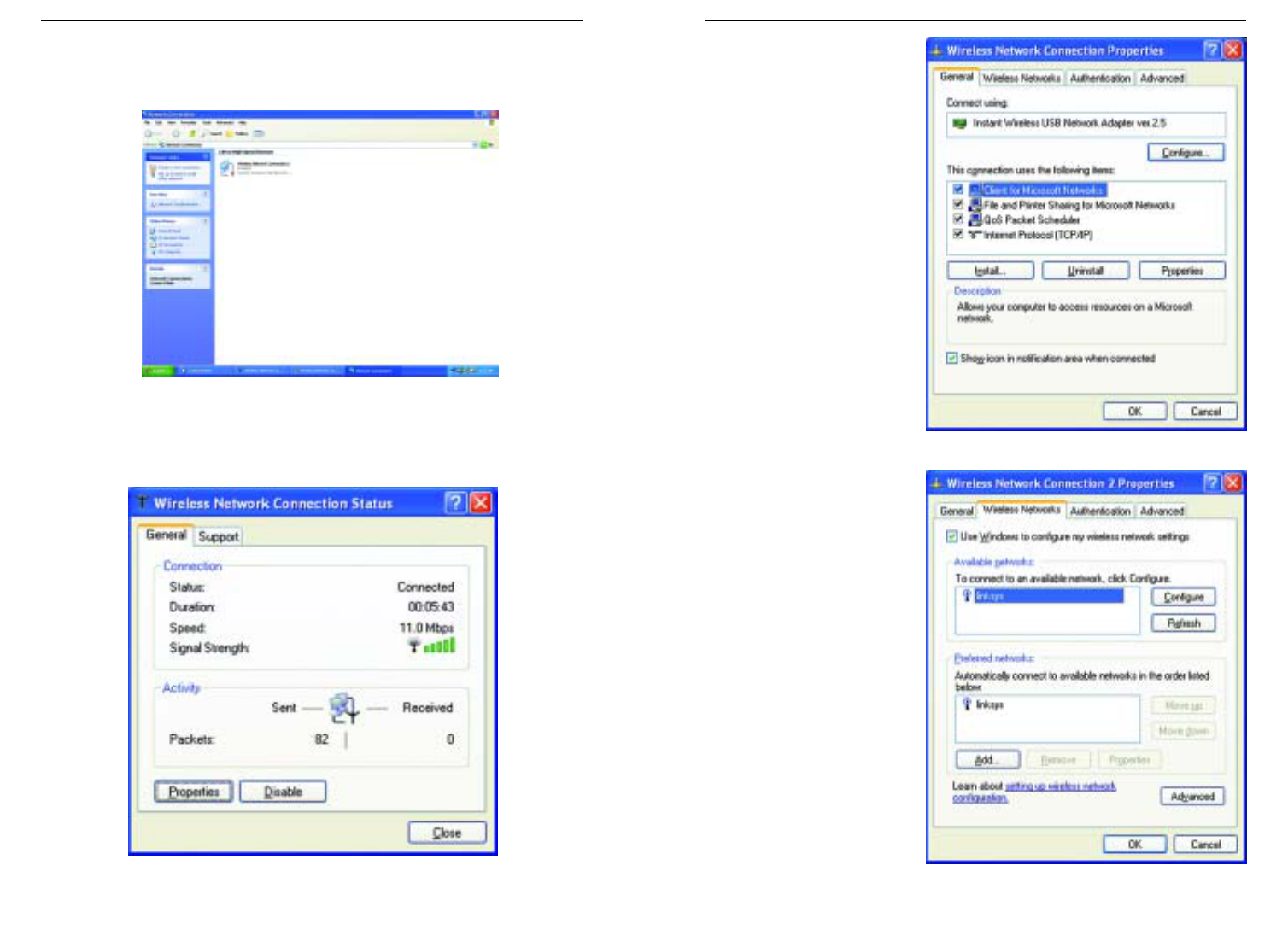
Wireless Cable/DSL Router
82
Network Everywhere®Series
81
6. When the “Wireless
Network Connection
Properties” window
appears, as in Figure C-
8, click the Wireless
Networks Tab.
7. If the appropriate wire-
less network, specified
by the Router’s SSID, is
displayed in the
“Preferred networks”
section, as shown in
Figure C-9, double-
click it and continue to
the next step.
Otherwise, click on the
appropriate wireless
network, specified by
the Router’s SSID, in
the “Available net-
works” section. Then,
click the Configure
button
Figure C-8
Figure C-9
If a “Connect to Wireless Network” window appears, in the Available
Networks section, click the desired wireless network, specified by the
Router’s SSID. Then, double-click the Wireless Network Connection icon.
5. When the “Wireless Network Connection Status” window appears, as in
Figure C-7, click the Properties button.
Figure C-6
Figure C-7
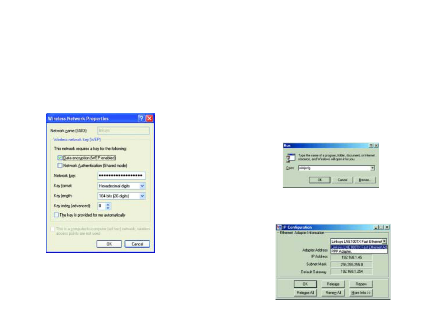
Wireless Cable/DSL Router
84
Network Everywhere®Series
83
Appendix D: Finding the MAC
Address and IP Address for Your
Ethernet Adapter
This section describes how to find the MAC address for your Ethernet adapter
to do either MAC Filtering or MAC Address Cloning for the Router and ISP.
You can also find the IP address of your computer’s Ethernet adapter. The IP
address is used for filtering, forwarding, and DMZ. Follow these steps to find
the MAC address or IP address for your adapter in Windows 98SE, ME, 2000,
and XP.
For Windows 98 SE and ME:
1. Click on Start and Run. In the Open field, enter winipcfg, as shown in
Figure D-1. Then press the Enter key or the OK button.
2. When the IP Configuration window appears, as shown in Figure D-2, select
the Ethernet adapter you are using to connect to the Router via a CAT 5
Ethernet cable.
Figure D-1
Figure D-2
8. The “Wireless Network Properties” window (shown in Figure C-10) will
appear.
Click the check box for the Data encryption (WEP enabled) option.
Remove the check from the Network Authentication (Shared mode) and
The key is provided for me automatically fields.
In the "Network key" field, enter the exact Key (all 10 or 26 digits, depend-
ing on the level of encryption) generated by the Router.
Verify that the “Key format” field displays “Hexadecimal digits” and that
the “Key length” field displays either “40 bits (10 digits)” or “104 bits (26
digits)”. If this is not displayed, you have entered the key incorrectly.
Click the OK button to save the settings. Click on OK buttons until you
get back to the “Wireless Network Connection Status” window. Close any
open windows to get back to the Windows XP desktop.
Close any applications and reboot your PC. After reboot, WEP configuration
is complete and you should be able to connect wirelessly to the Router.
Figure C-10
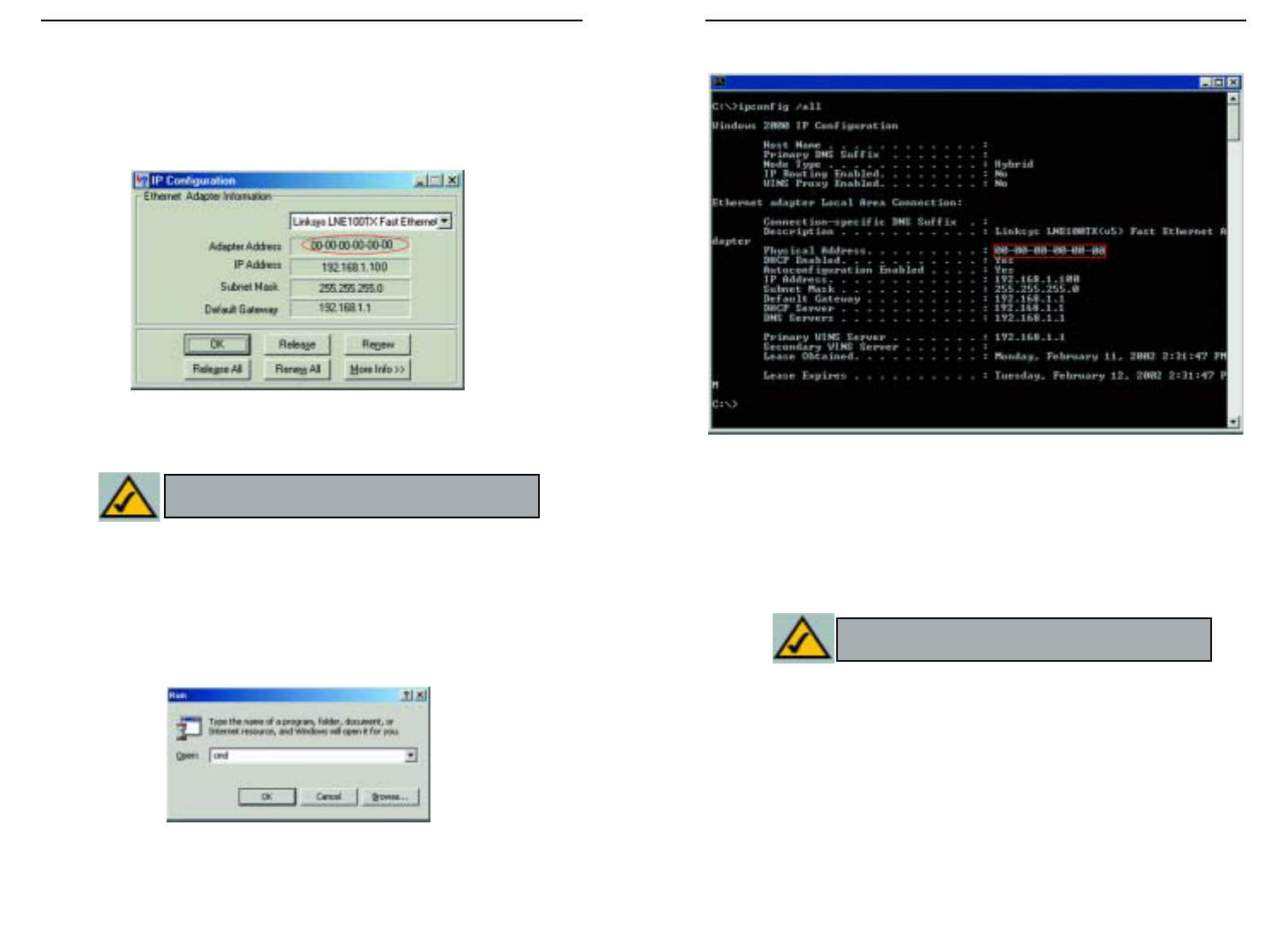
Wireless Cable/DSL Router
86
Network Everywhere®Series
85
2. In the command prompt, enter ipconfig /all. Then press the Enter key.
3. Write down the Physical Address as shown on your computer screen; it is
the MAC address for your Ethernet adapter. This will appear as a series of
letters and numbers.
The MAC address/Physical Address is what you will use for MAC Address
Cloning or MAC Filtering.
The example in Figure D-5 shows the IP address of your Ethernet adapter
as 192.168.1.100. Your computer may show something different.
Figure D-5
Note: The MAC address is also called the Physical
Address.
3. Write down the Adapter Address as shown on your computer screen (see
Figure D-3). This is the MAC address for your Ethernet adapter and will
be shown as a series of numbers and letters.
The MAC address/Adapter Address is what you will use for MAC Address
Cloning or MAC Filtering.
The example in Figure F-3 shows the IP address of your Ethernet adapter
as 192.168.1.100. Your computer may show something different.
For Windows 2000 and XP:
The following steps show an alternative way of obtaining the MAC address and
IP address for your Ethernet adapter.
1. Click on Start and Run. In the Open field, enter cmd, as shown in Figure
D-4. Press the Enter key or click the OK button.
Figure D-3
Figure D-4
Note: The MAC address is also called the Adapter
Address.
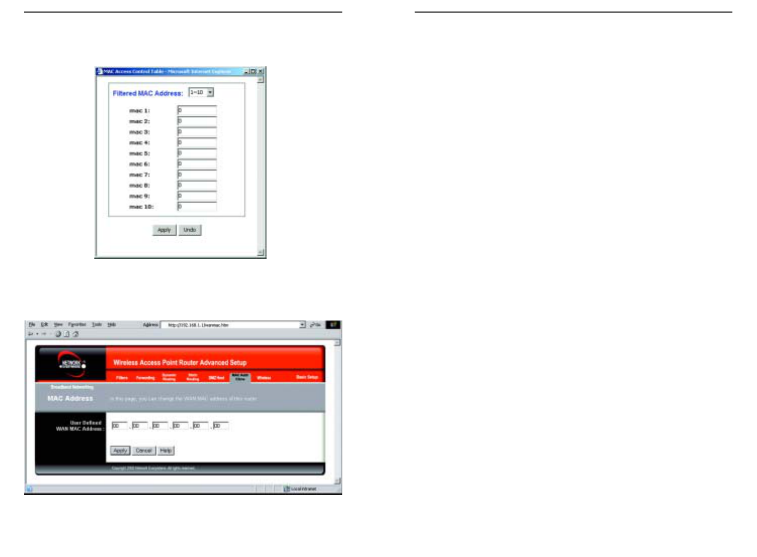
Wireless Cable/DSL Router
88
Network Everywhere®Series
87
Appendix E: Glossary
10BaseT - An Ethernet standard that uses twisted wire pairs.
100BaseTX - IEEE physical layer specification for 100 Mbps over two pairs of
Category 5 cable.
Adapter - Printed circuit board that plugs into a PC to add to capabilities or
connectivity to a PC. In a networked environment, a network interface card is
the typical adapter that allows the PC or server to connect to the intranet and/or
Internet.
Auto-negotiate - To automatically determine the correct settings. The term is
often used with communications and networking. For example, Ethernet
10/100 cards and switches can determine the highest speed of the node they are
connected to and adjust their transmission rate accordingly.
Bandwidth - The transmission capacity of a given facility, in terms of how
much data the facility can transmit in a fixed amount of time; expressed in bits
per second (bps).
Bit – A binary digit. The value—0 or 1—used in the binary numbering system.
Also, the smallest form of data.
Boot – To cause the computer to start executing instructions. Personal comput-
ers contain built-in instructions in a ROM chip that are automatically executed
on startup. These instructions search for the operating system, load it, and pass
control to it.
Bridge - A device that interconnects different networks together.
Broadband - A data-transmission scheme in which multiple signals share the
bandwidth of a medium. This allows the transmission of voice, data, and video
signals over a single medium. Cable television uses broadband techniques to
deliver dozens of channels over one cable.
Browser - A browser is an application program that provides a way to look at
and interact with all the information on the World Wide Web or PC. The word
“browser” seems to have originated prior to the Web as a generic term for user
interfaces that let you browse text files online.
Cable Modem - A device that connects a computer to the cable television net-
work, which in turn connects to the Internet. Once connected, cable modem
users have a continuous connection to the Internet. Cable modems feature
When entering the information using the Router’s web-based utility, you will
type the 12-digit MAC address in this format, XXXXXXXXXXXX without
the hyphens for MAC Filtering. See Figure D-6.
When entering information for MAC Address Cloning, type the 12-digit MAC
address (see Figure D-7).
Figure D-6
Figure D-7

Wireless Cable/DSL Router
DHCP supports static addresses for computers containing Web servers that
need a permanent IP address.
DMZ - (DeMilitarized Zone) allows one IP address (or computer) to be
exposed to the Internet. Some applications require multiple TCP/IP ports to be
open. It is recommended that you set your computer with a static IP address if
you want to use DMZ Hosting.
DNS - The Domain Name System (DNS) is the way that Internet domain
names are located and translated into Internet Protocol (IP) addresses. A
domain name is a meaningful and easy-to-remember “handle” for an Internet
address.
Domain - A subnetwork comprised of a group of clients and servers under the
control of one security database. Dividing LANs into domains improves per-
formance and security.
Download - To receive a file transmitted over a network. In a communications
session, download means receive, and upload means transmit.
Dynamic IP Address - An IP address that is automatically assigned to a client
station in a TCP/IP network, typically by a DHCP server. Network devices that
serve multiple users, such as servers and printers, are usually assigned static IP
addresses.
Dynamic Routing - The ability for a router to forward data via a different route
based on the current conditions of the communications circuits. For example,
it can adjust for overloaded traffic or failing lines and is much more flexible
than static routing, which uses a fixed forwarding path.
Ethernet - IEEE standard network protocol that specifies how data is placed
on and retrieved from a common transmission medium. Has a transfer rate of
10 Mbps. Forms the underlying transport vehicle used by several upper-level
protocols, including TCP/IP and XNS.
Firewall - A firewall is a set of related programs, located at a network gateway
server, that protects the resources of a network from users from other networks.
(The term also implies the security policy that is used with the programs.) An
enterprise with an intranet that allows its workers access to the wider Internet
installs a firewall to prevent outsiders from accessing its own private data
resources and for controlling what outside resources to which its own users
have access.
Basically, a firewall, working closely with a router, examines each network
packet to determine whether to forward it toward its destination.
90
Network Everywhere®Series
asymmetric transfer rates: around 36 Mbps downstream (from the Internet to
the computer), and from 200 Kbps to 2 Mbps upstream (from the computer to
the Internet).
CAT 5 - ANSI/EIA (American National Standards Institute/Electronic
Industries Association) Standard 568 is one of several standards that specify
“categories” (the singular is commonly referred to as “CAT”) of twisted pair
cabling systems (wires, junctions, and connectors) in terms of the data rates
that they can sustain. CAT 5 cable has a maximum throughput of 100 Mbps and
is usually utilized for 100BaseTX networks.
CSMA/CD (Carrier Sense Multiple Access/Collision Detection) - The LAN
access method used in Ethernet. When a device wants to gain access to the net-
work, it checks to see if the network is quiet (senses the carrier). If it is not, it
waits a random amount of time before retrying. If the network is quiet and two
devices access the line at exactly the same time, their signals collide. When the
collision is detected, they both back off and each waits a random amount of
time before retrying.
Data Packet - One frame in a packet-switched message. Most data communi-
cations is based on dividing the transmitted message into packets. For example,
an Ethernet packet can be from 64 to 1518 bytes in length.
Default Gateway - The routing device used to forward all traffic that is not
addressed to a station within the local subnet.
DHCP (Dynamic Host Configuration Protocol) - A protocol that lets network
administrators centrally manage and automate the assignment of Internet
Protocol (IP) addresses in an organization's network. Using the Internet’s set of
protocol (TCP/IP), each machine that can connect to the Internet needs a
unique IP address. When an organization sets up its computer users with a con-
nection to the Internet, an IP address must be assigned to each machine.
Without DHCP, the IP address must be entered manually at each computer and,
if computers move to another location in another part of the network, a new IP
address must be entered. DHCP lets a network administrator supervise and dis-
tribute IP addresses from a central point and automatically sends a new IP
address when a computer is plugged into a different place in the network.
DHCP uses the concept of a “lease” or amount of time that a given IP address
will be valid for a computer. The lease time can vary depending on how long a
user is likely to require the Internet connection at a particular location. It’s espe-
cially useful in education and other environments where users change fre-
quently. Using very short leases, DHCP can dynamically reconfigure networks
in which there are more computers than there are available IP addresses.
89

Wireless Cable/DSL Router
92
Network Everywhere®Series
91
ing the development and application of electrotechnology and allied sciences
for the benefit of humanity, the advancement of the profession, and the well-
being of our members.”
The IEEE fosters the development of standards that often become national and
international standards. The organization publishes a number of journals, has
many local chapters, and has several large societies in special areas, such as the
IEEE Computer Society.
IP Address - In the most widely installed level of the Internet Protocol (IP)
today, an IP address is a 32-binary digit number that identifies each sender or
receiver of information that is sent in packets across the Internet. When you
request an HTML page or send e-mail, the Internet Protocol part of TCP/IP
includes your IP address in the message (actually, in each of the packets if more
than one is required) and sends it to the IP address that is obtained by looking
up the domain name in the Uniform Resource Locator you requested or in the
e-mail address you're sending a note to. At the other end, the recipient can see
the IP address of the Web page requestor or the e-mail sender and can respond
by sending another message using the IP address it received.
IPCONFIG - A utility that provides for querying, defining and managing IP
addresses within a network. A commonly used utility, under Windows NT and
2000, for configuring networks with static IP addresses.
IPSec (Internet Protocol Security) - IPSec is a developing standard for securi-
ty at the network or packet processing layer of network communication. A big
advantage of IPSec is that security arrangements can be handled without
requiring changes to individual user computers.
ISP - An ISP (Internet service provider) is a company that provides individuals
and companies access to the Internet and other related services such as website
building and virtual hosting.
LAN - A local area network (LAN) is a group of computers and associated
devices that share a common communications line and typically share the
resources of a single processor or server within a small geographic area (for
example, within an office building).
Latency - The time delay between when the first bit of a packet is received and
the last bit is forwarded.
MAC Address - The MAC (Media Access Control) address is a unique num-
ber assigned by the manufacturer to any Ethernet networking device, such as a
network adapter, that allows the network to identify it at the hardware level.
Firmware - Code that is written onto read-only memory (ROM) or program-
mable read-only memory (PROM). Once firmware has been written onto the
ROM or PROM, it is retained even when the device is turned off.
Fragmentation - Breaking a packet into smaller units when transmitting over
a network medium that cannot support the original size of the packet.
FTP (File Transfer Protocol) - A protocol used to transfer files over a TCP/IP
network (Internet, UNIX, etc.). For example, after developing the HTML pages
for a website on a local machine, they are typically uploaded to the Web serv-
er using FTP.
FTP includes functions to log onto the network, list directories, and copy files.
It can also convert between the ASCII and EBCDIC character codes. FTP oper-
ations can be performed by typing commands at a command prompt or via an
FTP utility running under a graphical interface such as Windows. FTP transfers
can also be initiated from within a Web browser by entering the URL preceded
with ftp://.
Unlike e-mail programs in which graphics and program files have to be
“attached,” FTP is designed to handle binary files directly and does not add the
overhead of encoding and decoding the data.
Full Duplex - The ability of a device or line to transmit data simultaneously in
both directions.
Gateway – A device that interconnects networks with different, incompatible
communications protocols.
Half Duplex - Data transmission that can occur in two directions over a single
line, but only one direction at a time.
Hardware - Hardware is the physical aspect of computers, telecommunica-
tions, and other information technology devices. The term arose as a way to dis-
tinguish the “box” and the electronic circuitry and components of a computer
from the program you put in it to make it do things. The program came to be
known as the software.
HTTP (HyperText Transport Protocol) - The communications protocol used
to connect to servers on the World Wide Web. Its primary function is to estab-
lish a connection with a Web server and transmit HTML pages to the client
browser.
IEEE - The Institute of Electrical and Electronics Engineers. The IEEE
describes itself as “the world's largest technical professional society—promot-

Wireless Cable/DSL Router
RIP (Routing Information Protocol) - A simple routing protocol that is part of
the TCP/IP protocol suite. It determines a route based on the smallest hop count
between source and destination. RIP is a distance vector protocol that routine-
ly broadcasts routing information to its neighboring routers.
RJ-45 - A connector similar to a telephone connector that holds up to eight
wires, used for connecting Ethernet devices.
Router - Protocol-dependent device that connects subnetworks together.
Routers are useful in breaking down a very large network into smaller subnet-
works; they introduce longer delays and typically have much lower throughput
rates than bridges.
Server - Any computer whose function in a network is to provide user access
to files, printing, communications, and other services.
SMTP (Simple Mail Transfer Protocol) - The standard e-mail protocol on the
Internet. It is a TCP/IP protocol that defines the message format and the mes-
sage transfer agent (MTA), which stores and forwards the mail.
SNMP (Simple Network Management Protocol) - A widely used network
monitoring and control protocol. Data is passed from SNMP agents, which are
hardware and/or software processes reporting activity in each network device
(switch, router, bridge, etc.) to the workstation console used to oversee the net-
work. The agents return information contained in a MIB (Management
Information Base), which is a data structure that defines what is obtainable
from the device and what can be controlled (turned off, on, etc.).
Software - Instructions for the computer. A series of instructions that performs
a particular task is called a “program.” The two major categories of software are
“system software” and “application software.” System software is made up of
control programs such as the operating system and database management sys-
tem (DBMS). Application software is any program that processes data for the
user.
A common misconception is that software is data. It is not. Software tells the
hardware how to process the data.
Static IP Address - A permanent IP address that is assigned to a node in a
TCP/IP network.
Static Routing - Forwarding data in a network via a fixed path. Static routing
cannot adjust to changing line conditions as can dynamic routing.
94
Network Everywhere®Series
93
Mbps (MegaBits Per Second) - One million bits per second; unit of measure-
ment for data transmission.
mIRC - mIRC runs under Windows and provides a graphical interface for log-
ging onto IRC servers and listing, joining, and leaving channels.
NAT - NAT (Network Address Translation) is the translation of an Internet
Protocol address (IP address) used within one network to a different IP address
known within another network. One network is designated the inside network
and the other is the outside.
Network - A system that transmits any combination of voice, video, and/or
data between users.
Packet Filtering - Discarding unwanted network traffic based on its originat-
ing address or range of addresses or its type (e-mail, file transfer, etc.).
Ping (Packet INternet Groper) - An Internet utility used to determine whether
a particular IP address is online. It is used to test and debug a network by send-
ing out a packet and waiting for a response.
POP3 (Post Office Protocol 3) - A standard mail server commonly used on the
Internet. It provides a message store that holds incoming e-mail until users log
on and download it. POP3 is a simple system with little selectivity. All pending
messages and attachments are downloaded at the same time. POP3 uses the
SMTP messaging protocol.
Port - A pathway into and out of the computer or a network device such as a
switch or router. For example, the serial and parallel ports on a personal com-
puter are external sockets for plugging in communications lines, modems, and
printers.
PPPoE (Point to Point Protocol over Ethernet) - PPPoE is a method for the
encapsulation of PPP packets over Ethernet frames from the user to the ISP
over the Internet. One reason PPPoE is preferred by ISPs is because it provides
authentication (username and password) in addition to data transport. A PPPoE
session can be initiated by either a client application residing on a PC, or by
client firmware residing on a modem or router.
PPTP (Point-to-Point Tunneling Protocol) - A protocol which allows the Point
to Point Protocol (PPP) to be tunneled through an IP network. PPTP does not
specify any changes to the PPP protocol but rather describes a “tunneling serv-
ice” for carrying PPP (a tunneling service is any network service enabled by
tunneling protocols such as PPTP, L2F, L2TP, and IPSEC tunnel

Wireless Cable/DSL Router
the actual delivery of the data (routing), UDP takes care of keeping track of the
individual units of data (called packets) that a message is divided into for effi-
cient delivery over the network. UDP is known as a “connection-less” protocol
due to NOT requiring the receiver of a packet to return an acknowledgment of
receipt to the sender of the packet (as opposed to TCP).
Upgrade - To replace existing software or firmware with a newer version.
Upload - To send a file transmitted over a network. In a communications ses-
sion, upload means transmit, and download means receive.
URL (Uniform Resource Locator) - The address that defines the route to a file
on the Web or any other Internet facility. URLs are typed into the browser to
access Web pages, and URLs are embedded within the pages themselves to pro-
vide the hypertext links to other pages.
WAN (Wide Area Network) - A communications network that covers a rela-
tively large geographic area, consisting of two or more LANs. Broadband com-
munication over the WAN is often through public networks such as the tele-
phone (DSL) or cable systems, or through leased lines or satellites. In its most
basic definition, the Internet could be considered a WAN.
WINIPCFG - Configuration utility based on the Win32 API for querying,
defining, and managing IP addresses within a network. A commonly used util-
ity for configuring networks with static IP addresses.
Workgroup - Two or more individuals that share files and databases.
96
Network Everywhere®Series
Subnet Mask - The method used for splitting IP networks into a series of sub-
groups, or subnets. The mask is a binary pattern that is matched up with the IP
address to turn part of the host ID address field into a field for subnets.
Switch – 1. A data switch connects computing devices to host computers,
allowing a large number of devices to share a limited number of ports. 2. A
device for making, breaking, or changing the connections in an electrical cir-
cuit.
TCP (Transmission Control Protocol) - A method (protocol) used along with
the IP (Internet Protocol) to send data in the form of message units (datagram)
between network devices over a LAN or WAN. While IP takes care of handling
the actual delivery of the data (routing), TCP takes care of keeping track of the
individual units of data (called packets) that a message is divided into for effi-
cient delivery over the network. TCP is known as a “connection oriented” pro-
tocol due to requiring the receiver of a packet to return an acknowledgment of
receipt to the sender of the packet resulting in transmission control.
TCP/IP (Transmission Control Protocol/Internet Protocol) - The basic com-
munication language or set of protocols for communications over a network
(developed specifically for the Internet). TCP/IP defines a suite or group of
protocols and not only TCP and IP.
Telnet - A terminal emulation protocol commonly used on the Internet and
TCP/IP-based networks. It allows a user at a terminal or computer to log onto
a remote device and run a program.
TFTP (Trivial File Transfer Protocol) - A version of the TCP/IP FTP protocol
that has no directory or password capability.
Throughput - The amount of data moved successfully from one place to anoth-
er in a given time period.
Topology - A network’s topology is a logical characterization of how the
devices on the network are connected and the distances between them. The
most common network devices include switches, routers, and gateways. Most
large networks contain several levels of interconnection, the most important of
which include edge connections, backbone connections, and wide-area con-
nections.
TX Rate – Transmission Rate.
UDP (User Datagram Protocol) - A method (protocol) used along with the IP
(Internet Protocol) to send data in the form of message units (datagram)
between network devices over a LAN or WAN. While IP takes care of handling
95

Wireless Cable/DSL Router
98
Network Everywhere®Series
97
Appendix G: Warranty Information
BE SURE TO HAVE YOUR PROOF OF PURCHASE AND A BARCODE
FROM THE PRODUCT'S PACKAGING ON HAND WHEN CALLING.
RETURN REQUESTS CANNOT BE PROCESSED WITHOUT PROOF OF
PURCHASE.
IN NO EVENT SHALL NETWORK EVERYWHERE’S LIABILITY
EXCEED THE PRICE PAID FOR THE PRODUCT FROM DIRECT, INDI-
RECT, SPECIAL, INCIDENTAL, OR CONSEQUENTIAL DAMAGES
RESULTING FROM THE USE OF THE PRODUCT, ITS ACCOMPANYING
SOFTWARE, OR ITS DOCUMENTATION. NETWORK EVERYWHERE
DOES NOT OFFER REFUNDS FOR ANY PRODUCT.
NETWORK EVERYWHERE OFFERS CROSS SHIPMENTS, A FASTER
PROCESS FOR PROCESSING AND RECEIVING YOUR REPLACEMENT.
NETWORK EVERYWHERE PAYS FOR UPS GROUND ONLY. ALL CUS-
TOMERS LOCATED OUTSIDE OF THE UNITED STATES OF AMERICA
AND CANADA SHALL BE HELD RESPONSIBLE FOR SHIPPING AND
HANDLING CHARGES. PLEASE CALL NETWORK EVERYWHERE FOR
MORE DETAILS.
Appendix F: Specifications
Standards 802.11b, 802.3, 802.3u
Ports Four 10/100 switch ports, One Internet Port
Buttons Uplink
Cabling Type Ethernet Category 5 or better 10/100
LED Indicators WLAN(Act, Link) Power, Ethernet(Link/Act,
Full/Col, 100), Internet(Link, Act, Diag)
Transmit Power TX:16 dBm (40mW). RX: 11Mbps (-78dBm),
2Mbps (-82dBm) Gain: 2dBi
UPnP able/cert UPnP compatible
Security Features MAC, IP, time and port filtering. DoS prevention.
Dimensions 6.69" x 1.06" x 5.83"
(17 mm x 27 mm x 148 mm)
Unit Weight 15 oz. (0.42 kg)
Power 5V 2.0A
Certifications FCC, Wi-Fi
Operating Temp. 0°C to 55°C (32°F to 122°F)
Storage Temp. -40°C to 70°C (-40°F to 158°F)
Operating Humidity 20% to 95%, Non-condensing
Storage Humidity 20% to 95%, Non-condensing
Environmental

Network Everywhere®Series
Appendix H: Contact Information
For help with the installation or operation of the Wireless Cable/DSL Router,
contact Network Everywhere Technical Support at one of the phone numbers
or Internet addresses below.
Technical Support 949-271-5470, M-F, 8:00 am to 5:00 pm (PST)
Fax 949-265-6655
Email support@NetworkEverywhere.com
Web site http://www.NetworkEverywhere.com
99
Copyright © 2002 Network Everywhere. All rights reserved.
http://www.NetworkEverywhere.com