Cisco Linksys WAP55AG Dual-Band Wireless A+G Access Point User Manual WAP55AG UG
Cisco-Linksys, LLC Dual-Band Wireless A+G Access Point WAP55AG UG
Contents
- 1. Users Manual Part 1
- 2. Users Manual Part 2
Users Manual Part 1
Instant Wireless®Series
Dual-Band Wireless
A + G Access Point
Use this guide to install: WAP55AG User Guide

COPYRIGHT & TRADEMARKS
Specifications are subject to change without notice. Copyright © 2003 Linksys, All Rights
Reserved. Instant Wireless, Linksys, and the Linksys logo are registered trademarks of
Linksys Group, Inc. Microsoft, Windows, and the Windows logo are registered trade-
marks of Microsoft Corporation. All other trademarks and brand names are the proper-
ty of their respective proprietors.
LIMITED WARRANTY
Linksys guarantees that every Instant Wireless Dual-Band Wireless A + G Access Point
will be free from physical defects in material and workmanship for one year from the date
of purchase, when used within the limits set forth in the Specifications section of this User
Guide.
If the product proves defective during this warranty period, go to the Linksys website at
www.linksys.com
for complete Return Merchandise Authorization (RMA) assistance. You
can also call Linksys Technical Support in order to obtain a RMA Number. BE SURE TO
HAVE YOUR PROOF OF PURCHASE AND A BARCODE FROM THE PRODUCT’S PACK-
AGING ON HAND WHEN CALLING. RETURN REQUESTS CANNOT BE PROCESSED
WITHOUT PROOF OF PURCHASE. When returning a product, mark the RMA Number
clearly on the outside of the package and include a copy of your original proof of pur-
chase. All customers located outside of the United States of America and Canada shall
be held responsible for shipping and handling charges.
IN NO EVENT SHALL LINKSYS'S LIABILITY EXCEED THE PRICE PAID FOR THE PROD-
UCT FROM DIRECT, INDIRECT, SPECIAL, INCIDENTAL, OR CONSEQUENTIAL DAM-
AGES RESULTING FROM THE USE OF THE PRODUCT, ITS ACCOMPANYING SOFT-
WARE, OR ITS DOCUMENTATION. LINKSYS OFFERS NO REFUNDS FOR ITS PROD-
UCTS. Linksys makes no warranty or representation, expressed, implied, or statutory,
with respect to its products or the contents or use of this documentation and all accom-
panying software, and specifically disclaims its quality, performance, merchantability, or
fitness for any particular purpose. Linksys reserves the right to revise or update its prod-
ucts, software, or documentation without obligation to notify any individual or entity.
Please direct all inquiries to:
Linksys P.O. Box 18558, Irvine, CA 92623.
SAFETY AND REGULATORY NOTICES
FCC STATEMENT
The Instant Wireless Dual-Band Wireless A + G Access Point has been tested and com-
plies with the specifications for a Class B digital device, pursuant to Part 15 of the FCC
Rules. Operation is subject to the following two conditions:
(1) This device may not cause harmful interference, and
(2) This device must accept any interference received, including interference that may
cause undesired operation.
These limits are designed to provide reasonable protection against harmful interference
in a residential installation. This equipment generates, uses, and can radiate radio fre-
quency energy and, if not installed and used according to the instructions, may cause
harmful interference to radio communications. However, there is no guarantee that inter-
ference will not occur in a particular installation. If this equipment does cause harmful
interference to radio or television reception, which is found by turning the equipment off
and on, the user is encouraged to try to correct the interference by one or more of the
following measures:
• Reorient or relocate the receiving antenna
• Increase the separation between the equipment or devices
• Connect the equipment to an outlet other than the receiver's
• Consult a dealer or an experienced radio/TV technician for assistance
FCC Caution: Any change or modification to the product not expressly approved by
Linksys could void the user's authority to operate the device.
FCC Caution: Operation within the 5150 to 5250GHz band is restricted to indoor use only.
FCC RF Radiation Exposure Statement
To comply with the FCC and ANSI C95.1 RF exposure limits, the antenna(s) for this
device must comply with the following:
• Access points with 2.4 GHz or 5 GHz integrated antenna must operate with a sepa-
ration distance of at least 20 cm from all persons using the cable provided and must
not be co-located or operating in conjunction with any other antenna or transmitter.
End-users must be provided with specific operations for satisfying RF exposure compli-
ance.
Note: Dual antennas used for diversity operation are not considered co-located.
Canadian Department of Communications Industry Canada (IC) Notice
This Class B digital apparatus complies with Canadian ICES-003 and RSS-210.
Cet appareil numérique de la classe B est conforme à la norme NMB-003 et CNR-210
du Canada.
"To prevent radio interference to the licensed service, this device is intended to be oper-
ated indoors and away from windows to provide maximum shielding. Equipment (or its
transmit antenna) that is installed outdoors is subject to licensing."
" Pour empêcher que cet appareil cause du brouillage au service faisant l'objet d'une
licence, il doit être utilisé à l'intérieur et devrait être placé loin des fenêtres afin de fournir
un écran de blindage maximal. Si le matériel (ou son antenne d'émission) est installé à
l'extérieur, il doit faire l'objet d'une licence. "
EC DECLARATION OF CONFORMITY (EUROPE)
Linksys Group declares that the Instant Wireless®Series products included in the Instant
Wireless®Series conform to the specifications listed below, following the provisions of the
European R&TTE directive 1999/5/EC, EMC directive 89/336/EEC, and Low Voltage
directive 73/23/EEC:
For 11Mbps, 2.4 GHz access points with 100 mW radios, the following standards were
applied:
• ETS 300-826, 301 489-1 General EMC requirements for Radio equipment.
• EN 609 50 Safety
• ETS 300-328-2 Technical requirements for Radio equipment.
For 54 Mbps, 5 GHz access points with 40 mW radios, the following standards were
applied:
• ETS 301 489-1, 301 489-17 General EMC requirements for Radio equipment.
• EN 609 50 Safety
• ETS 301-893 Technical requirements for Radio equipment.
Caution: The frequencies used by 802.11a wireless LAN devices are not yet harmonized
within the European community, 802.11a products are designed for use only in specific
countries, and are not allowed to be operated in countries other than those of designat-
ed use. Contact local Authority for procedure to follow.
Caution: This equipment is intended to be used in all EU and EFTA countries. Outdoor
use may be restricted to certain frequencies and/or may require a license for operation.
Contact local Authority for procedure to follow.

Dual-Band Wireless A + G Access Point
Table of Contents
Chapter 1: Introduction 1
The Instant Wireless Dual-Band Wireless A + G Access Point 1
Features 1
Chapter 2: Planning Your Wireless Network 2
Network Topology 2
Roaming 2
Chapter 3: Getting to Know the Dual-Band
Wireless A + G Access Point 3
The Access Point’s Back Panel 3
The Access Point’s Front Panel 4
Chapter 4: Connecting the Dual-Band
Wireless A + G Access Point 5
Chapter 5: Setting Up the Dual-Band
Wireless A + G Access Point 6
Chapter 6: Configuring the Dual-Band
Wireless A + G Access Point 14
The Setup Tab 14
WEP Encryption 16
The Password Tab 18
The Status Tab 19
The Statistics Tab 19
The Log Tab 20
The Help Tab 20
The Filters Tab 21
The Advanced Wireless Tab 22
The SNMP Tab 25
Appendix A: Troubleshooting 26
Frequently Asked Questions 26
Note: Combinations of power levels and antennas resulting in a radiated power level of
above 100 mW equivalent isotropic radiated power (EIRP) are considered as not com-
pliant with the above mentioned directive and are not allowed for use within the European
community and countries that have adopted the European R&TTE directive 1999/5/EC
and/or the CEPT recommendation Rec 70.03.
For more details on legal combinations of power levels and antennas, contact Linksys
Corporate Compliance.
• Linksys Group vakuuttaa täten että Instant Wireless Dual-Band Wireless A + G
Access Point tyyppinen laite on direktiivin 1999/5/EY, direktiivin 89/336/EEC ja direk-
tiivin 73/23/EEC oleellisten vaatimusten ja sitä koskevien näiden direktiivien muiden
ehtojen mukainen.
• Linksys Group déclare que la Instant Wireless Dual-Band Wireless A + G Access
Point est conforme aux conditions essentielles et aux dispositions relatives à la direc-
tive 1999/5/EC, la directive 89/336/EEC, et à la directive 73/23/EEC.
• Belgique B L'utilisation en extérieur est autorisé sur le canal 11 (2462 MHz), 12 (2467
MHz), et 13 (2472 MHz). Dans le cas d'une utilisation privée, à l'extérieur d'un bâti-
ment, au-dessus d'un espace public, aucun enregistrement n'est nécessaire pour
une distance de moins de 300m. Pour une distance supérieure à 300m un enreg-
istrement auprès de l'IBPT est requise. Pour une utilisation publique à l'extérieur de
bâtiments, une licence de l'IBPT est requise. Pour les enregistrements et licences,
veuillez contacter l'IBPT.
• France F:
2.4 GHz Bande : les canaux 10, 11, 12, 13 (2457, 2462, 2467, et 2472 MHz respec-
tivement) sont complétement libres d'utilisation en France (en utilisation intérieur).
Pour ce qui est des autres canaux, ils peuvent être soumis à autorisation selon le
départment. L'utilisation en extérieur est soumis à autorisation préalable et très
restreint.
5 GHz Bande: Conformément aux décisions de la CEPT, l'utilisation des fréquences
de la bande 5150 MHz - 5350 MHz est autorisée à l'intérieur des bâtiments avec une
puissance maximale de 200 mW, et interdite en extérieur. La bande 5470 MHz - 5725
MHz n'est pas ouverte aujourd'hui.
Vous pouvez contacter l'Autorité de Régulation des Télécommunications
(http://www.art-telecom.fr) pour de plus amples renseignements.
2.4 GHz Band: only channels 10, 11, 12, 13 (2457, 2462, 2467, and 2472 MHz
respectively) may be used freely in France for indoor use. License required for out-
door installations.
5 GHz Band: frequencies in the 5150 MHz - 5350 MHz band may be used indoor
with maximum power of 200 mW. Their use is forbidden outdoors. The 5470 MHz -
5725 MHz band is not currently open.
Please contact ART (http://www.art-telecom.fr) for procedure to follow.
• Deutschland D: Anmeldung im Outdoor-Bereich notwending, aber nicht genehmi-
gungspflichtig. Bitte mit Händler die Vorgehensweise abstimmen.
• Germany D: License required for outdoor installations. Check with reseller for proce-
dure to follow.
• Italia I: E' necessaria la concessione ministeriale anche per l'uso interno. Verificare
con i rivenditori la procedura da seguire. L'uso per installazione in esterni non e' per-
messa.
• Italy I: License required for indoor use. Use with outdoor installations not allowed.
• The Netherlands NL License required for outdoor installations. Check with reseller for
procedure to follow.
• Nederlands NL Licentie verplicht voor gebruik met buitenantennes. Neem contact op
met verkoper voor juiste procedure.
UG-WAP55AG-30214NC KL

Instant Wireless® Series Dual-Band Wireless A + G Access Point
Chapter 1: Introduction
The Linksys Dual-Band Wireless A+G Access Point gives you universal wireless
connectivity. It's the best way to add wireless capability to your existing wired
network, or to add bandwidth to your wireless installation.
The Dual-Band Wireless A+G Access Point actually contains two separate wire-
less connectivity radio transceivers, which support all three popular wireless net-
working specifications. The first transceiver uses the 2.4GHz radio band, sup-
porting both the widely-used and inexpensive Wireless-B (802.11b) standard at
11Mbps, and the new, almost five times faster, Wireless-G (draft 802.11g) at
54Mbps. The second radio operates in the 5GHz band, and supports Wireless-A
(802.11a) networking, also at 54Mbps. Since the two radios operate in different
bands, they can work simultaneously, blanketing your wireless zone with high-
speed bandwidth.
To protect your data and privacy, the A+G Access Point can encrypt all wireless
transmissions. The MAC Address filter lets you decide exactly who has access
to your wireless network while Dynamic Frequency Selection (DFS) puts your
network on the cleanest channel in your location. Configuration is a snap with
the web browser-based configuration utility.
With the Linksys Dual-Band Wireless A+G Access Point, you'll have the best of
all worlds -- Wireless-B for legacy compatibility, and both Wireless-G and
Wireless-A for high-speed access.
• Dual-band, tri-standard Access Point communicates with Wireless-A
(802.11a), Wireless-B (802.11b), and Wireless-G (draft 802.11g) wireless
networks
• Protect your wireless investment while preparing your infrastructure for the
future
• Advanced features: SNMP manageability, and Dynamic Frequency Selection
(DFS)
• Powerful security: Up to 152-bit wireless data encryption (WEP), and wire-
less MAC address filter
• Performance Investment Protection: Compatibility with Wireless-A
(802.11a), Wireless-B (802.11b) and Wireless-G (draft 802.11g) Standards
• Ideal Wireless Solution for Enterprise customers
• MAC Address Filtering and up to 152-bit WEP Encryption
• Built in Web UI for easy configuration from any Web Browser
• Firmware upgradeable through Web-browser
• Quick Setup and Easy for Deployment
• Free Technical Support - 24 Hours a Day, 7 Days a Week, Toll-Free U.S. Calls
• 1-Year Limited Warranty
1
Features
Appendix B: Setting Up the TCP/IP and
IPX Protocols 31
Setting Up TCP/IP in Windows 31
TCP/IP Setup for Windows 95, 98, and Millennium 32
IPX Setup for Windows 95, 98, and Millennium 32
TCP/IP Setup for Windows NT 4.0 33
IPX Setup for Windows NT 4.0 33
TCP/IP Setup for Windows 2000 34
IPX Setup for Windows 2000 34
TCP/IP Setup for Windows XP 35
Appendix C: Glossary 36
Appendix D: Specifications 46
Environmental 47
Appendix E: Warranty Information 48
Appendix F: Contact Information 49
The Instant Wireless Dual-Band Wireless A + G Access Point
Dual-Band Wireless A + G Access Point
Chapter 3: Getting to Know the Dual-
Band Wireless A + G Access Point
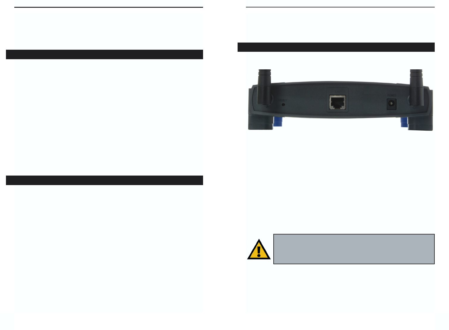
The Access Point’s ports, where a network cable is connected, are located on
the Access Point’s back panel, shown in Figure 3-1.
LAN This LAN (Local Area Network) port connects to Ethernet net-
work devices, such as a hub, switch, or router.
Power The Power port is where you will connect the power adapter.
Reset Button There are two ways to Reset the Access Point’s factory
defaults. Either press the Reset Button, for approximately ten
seconds, or restore the defaults from the password tab in the
Access Point’s Web-Based Utility.
32
The Access Point’s Back Panel
Figure 3-1
Important: Resetting the Access Point will erase all of your settings
(WEP Encryption, Wireless and LAN settings, etc.) and replace
them with the factory defaults. Do not reset the Access Point if you
want to retain these settings
Chapter 2: Planning Your
Wireless Network
A wireless LAN is a group of computers, each equipped with one Instant
Wireless Series adapter. Computers in a wireless LAN must be configured to
share the same radio channel.
The Instant Wireless Series adapters provide access to a wired LAN for wire-
less workstations. An integrated wireless and wired LAN is called an infra-
structure configuration. A group of Instant Wireless Series adapter users and
an Access Point compose a Basic Service Set (BSS). Each Instant Wireless
Series adapter PC in a BSS can talk to any computer in a wired LAN infra-
structure via the Access Point.
An infrastructure configuration extends the accessibility of an Instant Wireless
Series adapter PC to a wired LAN, and doubles the effective wireless trans-
mission range for two Instant Wireless Series adapter PCs. Since the Access
Point is able to forward data within its BSS, the effective transmission range in
an infrastructure LAN is doubled.
Infrastructure mode also supports roaming capabilities for mobile users. More
than one BSS can be configured as an Extended Service Set (ESS). This con-
tinuous network allows users to roam freely within an ESS. All PCs equipped
with an Instant Wireless Series adapter within one ESS must be configured
with the same ESS ID and use the same radio channel.
Before enabling an ESS with roaming capability, choosing a feasible radio
channel and optimum Access Point position is recommended. Proper Access
Point positioning combined with a clear radio signal will greatly enhance per-
formance.
Roaming
Network Topology
Instant Wireless® Series
Dual-Band Wireless A + G Access Point
Chapter 4: Connecting the Dual-
Band Wireless A + G Access Point
1. Locate an optimum location for the Access Point. The best place for the
Access Point is usually at the center of your wireless network, with line of
sight to all of your mobile stations.
2. Fix the direction of the antenna. Try to place it in a position which can
best cover your wireless network. Normally, the higher you place the anten-
na, the better the performance will be. The antenna’s position enhances the
receiving sensitivity.
3. Connect a standard Ethernet network cable to the Access Point. Then,
connect the other end to a PC or to your wired network.
4. Connect the AC Power Adapter to the Access Point’s Power Socket.
Only use the power adapter supplied with the Access Point. Use of a differ-
ent adapter may result in product damage.
Now that the hardware installation is complete, proceed to Chapter 5: Setting
Up the Dual-Band Wireless A + G Access Point for directions on how to set
up the Access Point.
5
Instant Wireless® Series
4
Note: In order for all other wireless devices to communicate with
the Access Point, those devices must be operating in the
Infrastructure Mode. If any wireless devices are configured in
the Ad Hoc Mode, they will not be recognized by the Access Point.
T
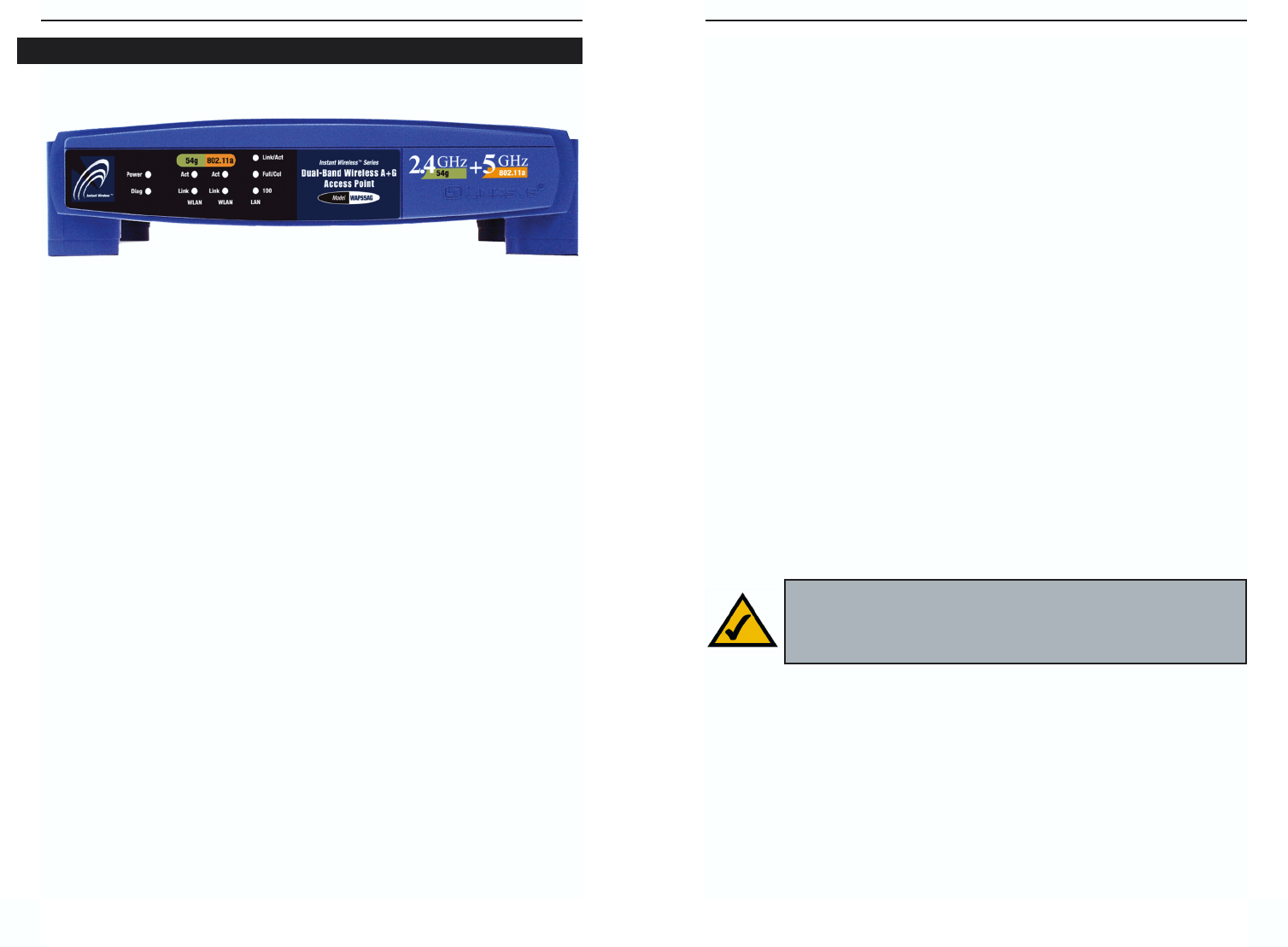
The LEDs on the Access Point’s front panel, shown in Figure 3-2, display net-
work activity.
Power Green. The Power LED lights up when the Access Point is
powered on.
Diag Red. The Diag LED indicates the Access Point’s self-diagnosis
mode during boot-up and restart. It will turn off upon com-
pleting the diagnosis. If this LED stays on for an abnormally
long period of time, refer to the Troubleshooting Appendix.
WLAN Act Green. If the WLAN’s Act LED is flickering, the Access Point
is actively sending or receiving data to or from one of the
devices on the network.
WLAN Link Green. The WLAN’s Link LED lights whenever there is a suc-
cessful wireless connection.
LAN Act/Link Green. The LAN’s LINK LED serves two purposes. If the
LED is continuously lit, the Access Point is successfully con-
nected to a device through the LAN port. If the LED is flick-
ering, it is an indication of any network activity.
LAN Full/Col Green. The LAN’s Full/Col LED also serves two purposes.
When this LED is continuously lit, the connection made
through the corresponding port is running in Full Duplex
mode. A flickering LED indicates that the connection is expe-
riencing collisions. Infrequent collisions are normal. If this
LED blinks too often, there may be a problem with your con-
nection. Refer to the Troubleshooting Appendix if you think
there is a problem.
LAN 100 Orange. The LAN’s 100 LED indicates when a successful
100Mbps connection is made through the LAN port.
The Access Point’s Front Panel
Figure 3-2
Dual-Band Wireless A + G Access Point
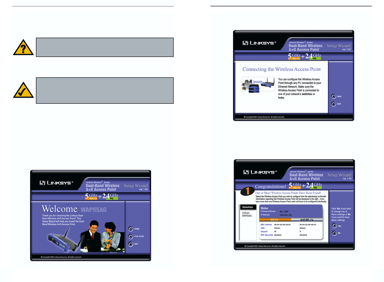
3. The following screen, shown in Figure 5-2, displays how to connect the
Access Point. You can also configure the Access Point through one of your
PC’s ethernet ports. Click the Next button to continue.
4. The next screen to appear, shown in Figure 5-3, will display a list of access
points on your network along with the status information for each access
point. Choose this Access Point for configuration and click the Ye s button
to continue.
7
Chapter 5: Setting Up the Dual-
Band Wireless A + G Access Point
Now that you’ve connected the Access Point to your wired network, you are
ready to begin setting it up. This Setup Wizard will take you through all the
steps necessary to configure the Access Point.
1. Insert the Setup Wizard CD into your PC’s CD-ROM drive. Your PC must
be on your wired network to set up the Access Point.
2. The screen in Figure 5-1 should appear on your monitor. If it does not, this
means the autorun is not functioning. Start the Setup Wizard manually by
clicking the Start button, selecting Run, and typing d:\setup.exe (where
“D” is your PC’s CD-ROM drive). Click the Setup button to continue this
Setup Wizard. Clicking the User Guide button opened this User Guide. To
access the Linksys web site on an active Internet connection, click the
Linksys Web button or to exit this Setup Wizard, click the Exit button.
6
Figure 5-2
Figure 5-3
Have You: Connected the Access Point to a PC or available port on
your wired network as described in Chapter 4: Connecting the
Dual-Band Wireless A + G Access Point?
Note: While the Access Point has been designed to work correctly
right out of the box, setting it up on a wireless computer will require
you to use the Linksys default settings. These settings can then be
changed with the Setup Wizard or Web-based Browser Utility.
Figure 5-1
Instant Wireless® Series
Dual-Band Wireless A + G Access Point
9
Instant Wireless® Series
8
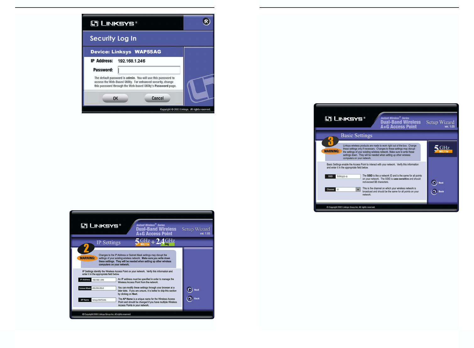
7. As shown in Figure 5-6, the Basic Settings screen for your 5 GHz/802.11a
wireless products will appear. Enter your wireless network’s SSID and
select the channel at which the network broadcasts its wireless signal. Then,
click the Next button to continue.
SSID. The SSID is the unique name shared among all points in a wireless
network. The SSID must be identical for all points in the wireless network.
It is case sensitive and must not exceed 32 characters, which may be any
keyboard character. The default SSID, linksys-a, should be changed for
greater security. Make sure this setting is the same for all points in your
wireless network.
Channel. Select
the appropriate
channel from
the list provided
to correspond
with your net-
work settings,
between 36 and
64. All points in
your wireless
network must
use the same
channel in order
to function cor-
rectly.
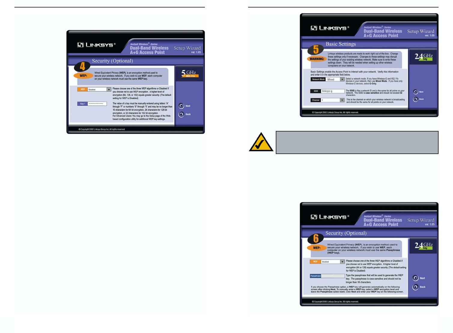
8. The Security Settings screen (Figure 5-7) for your 5 GHz/802.11a wireless
products will appear next. From this screen, you will set the Wired
Equivalent Privacy (WEP) encryption, 64-bit/128-bit/152-bit, for your
wireless network. Select a WEP configuration method and a WEP key.
Figure 5-6
5. You will be asked to
sign onto the Access
Point you’ve select-
ed, as shown in
Figure 5-4. Enter the
default password:
admin. Then, click
the OK button. (This
password should be
changed from the
Web-based Utility’s
Password tab for
greater security.)
6. As shown in Figure 5-5, the IP Settings screen will appear next. Enter an
IP Address, Subnet Mask, and enter a unique access point name for the
Access Point appropriate to your network. Then, click the Next button to
continue.
IP Address. This IP address must be unique to your network. (The default
IP address is 192.168.1.246.)
Subnet Mask. The Access Point’s Subnet Mask must be the same as your
Ethernet network.
Access Point
Name. Assign a
name to the
Access Point.
Unique, memo-
rable names are
helpful, espe-
cially if you are
employing mul-
tiple access
points on the
same network.
Figure 5-4
Figure 5-5
Dual-Band Wireless A + G Access Point
11
Instant Wireless® Series
The WEP key can consist of the letters “A” through “F” and the numbers
“0” through “9” and should be 10 characters in length for 64-bit encryption,
26 characters in
length for 128-
bit encryption,
or 32 characters
in length for
152-bit encryp-
tion. All points
in your wireless
network must
use the same
WEP key to uti-
lize WEP
encryption.
Click the Next
button to contin-
ue.
9. As shown in Figure 5-8, the Basic Settings screen for your 2.4 GHz/802.11g
wireless products will appear. Enter your wireless network’s SSID and
select the channel at which the network broadcasts its wireless signal. Then,
click the Next button to continue.
Network Mode. Since 802.11g-draft products are backwards compatible
with 802.11b products, this mode is provided in the event you wish to incor-
porate 802.11b products into you 802.11g-draft wireless network. If you are
using both 802.11g-draft and 802.11b products in your network, select
Mixed mode. You may experience reduced networking speeds in Mixed
mode, as the speed must compensate for both types. If you are only using
802.11g-draft products in your network, select G-Only mode.
SSID. The SSID is the unique name shared among all points in a wireless
network. The SSID must be identical for all points in the wireless network.
It is case sensitive and must not exceed 32 characters, which may be any
keyboard character. The default SSID, linksys-g, should be changed for
greater security. Make sure this setting is the same for all points in your
wireless network.
10
Channel. Select
the appropriate
channel from the
list provided to
correspond with
your network
settings,
between 1 and
11 (in North
America). All
points in your
wireless network
must use the
same channel in
order to function
correctly.
10. The Security Settings screen (Figure 5-9) for your 2.4 GHz/802.11g-draft
wireless products will appear next. From this screen, you will set the Wired
Equivalent Privacy (WEP) encryption, 64-bit/128-bit, for your wireless net-
work. Select a WEP configuration method and a WEP passphrase.
WEP (Disable/64-bit WEP/128-bit WEP). In order to utilize WEP encryp-
tion, select the
WEP setting
from the pull-
down menu. If
you do not wish
to utilize WEP
encryption,
make sure
Disable is
selected.
Note: WEP encryption should be used whenever networking wire-
lessly. WEP encryption helps increase security and make your
wireless network safer to use.
Figure 5-8
Figure 5-9
Figure 5-7
Dual-Band Wireless A + G Access Point
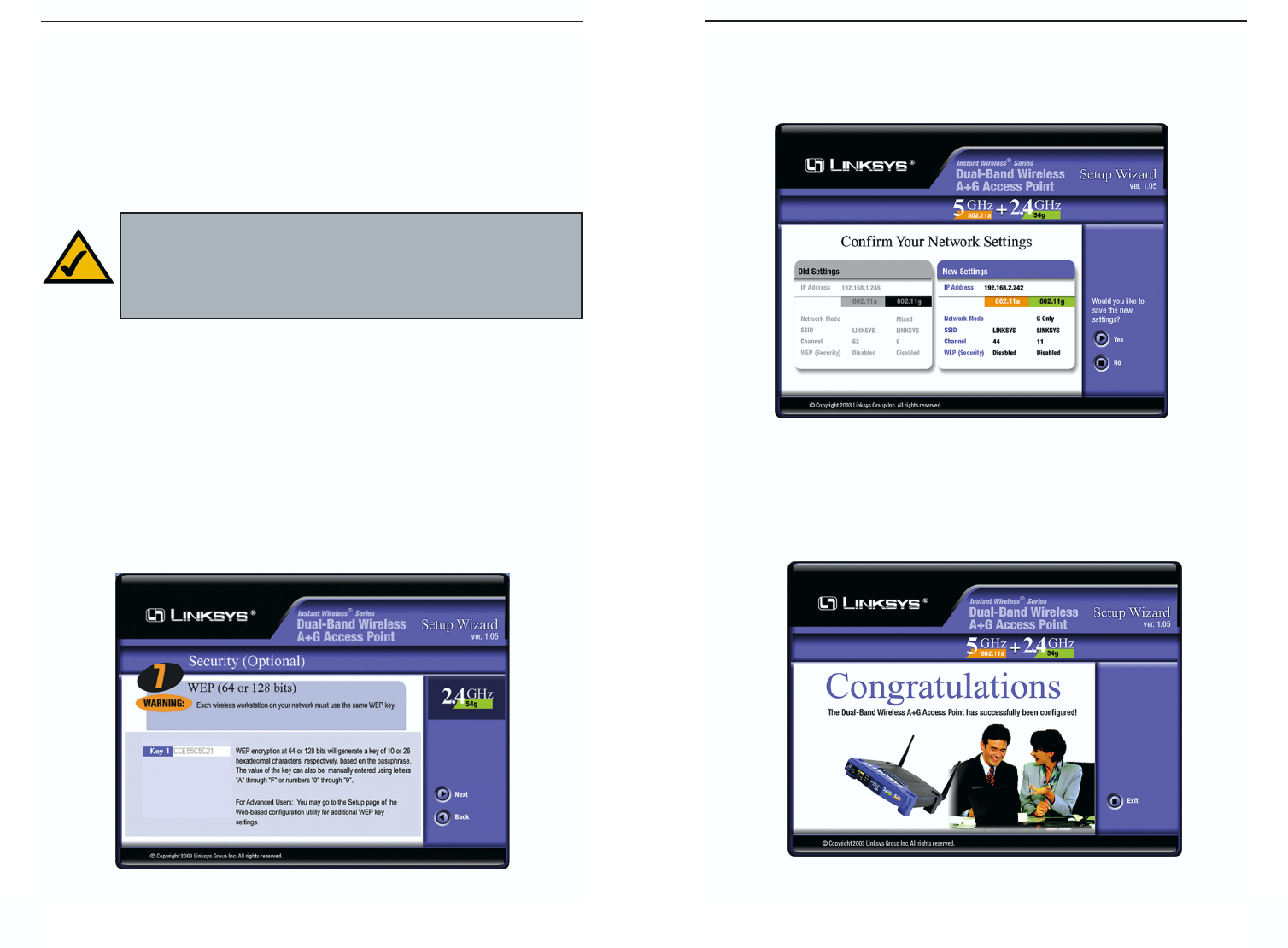
12. You should now review the settings you’ve chosen, as shown in Figure 5-
11. If these settings are correct, click the Ye s button to save these settings.
If you wish to change any of the settings, click the No button. You will exit
the Setup Wizard and can start it again to revise your settings.
13. At this point, the configuration performed with the Setup Wizard is com-
plete, as shown in Figure 5-12. To configure any other Access Points in your
network, you can run this Setup Wizard again. Click the Exit button to exit
the Setup Wizard.
1312
Figure 5-12
Figure 5-11
Passphrase. This is a text string with a maximum of 16 alphanumeric char-
acters used for generating a WEP Key. Type the passphrase here. This
passphrase may not work with non-Linksys products due to possible incom-
patibility with other vendors’ passphrase generators. If you’d rather not use
a passphrase and would rather enter the WEP Key manually, click the Next
button.
Click the Next button to continue.
11. The following Security screen, shown in Figure 5-7, will allow you to enter
your WEP key if a passphrase was not entered on the previous screen. If a
passphrase was used, the new WEP key will appear on this screen. Each
point in your wireless network must use the same WEP key for the network
to function properly. Verify that the appropriate key is entered and click the
Next button to continue.
The WEP key can consist of the letters “A” through “F” and the numbers
“0” through “9” and should be 10 characters in length for 64-bit encryption
or 26 characters in length for 128-bit encryption. All points in your wireless
network must use the same WEP key to utilize WEP encryption.
Note: The Access Point’s passphrase function when mixing prod-
ucts from other manufacturers into your wireless network. Linksys
products should always be used for optimum functionality. If
another company’s wireless product is used, however, the WEP key
should be set manually.
Figure 5-10
Instant Wireless® Series