Cisco Systems 102044 AIR-CB20A-A-K9 User Manual winincfgb
Cisco Systems Inc AIR-CB20A-A-K9 winincfgb
UserManual.wiki
>
Cisco Systems
>
102044 User Manual
>
User Manual Part 2
Contents
1.
User Manual Part 1
2.
User Manual Part 2
User Manual Part 2
Navigation menu
Upload a User Manual
Namespaces
Wiki Guide
HTML
PDF
Info
Views
User Manual
Discussion / Help
Navigation
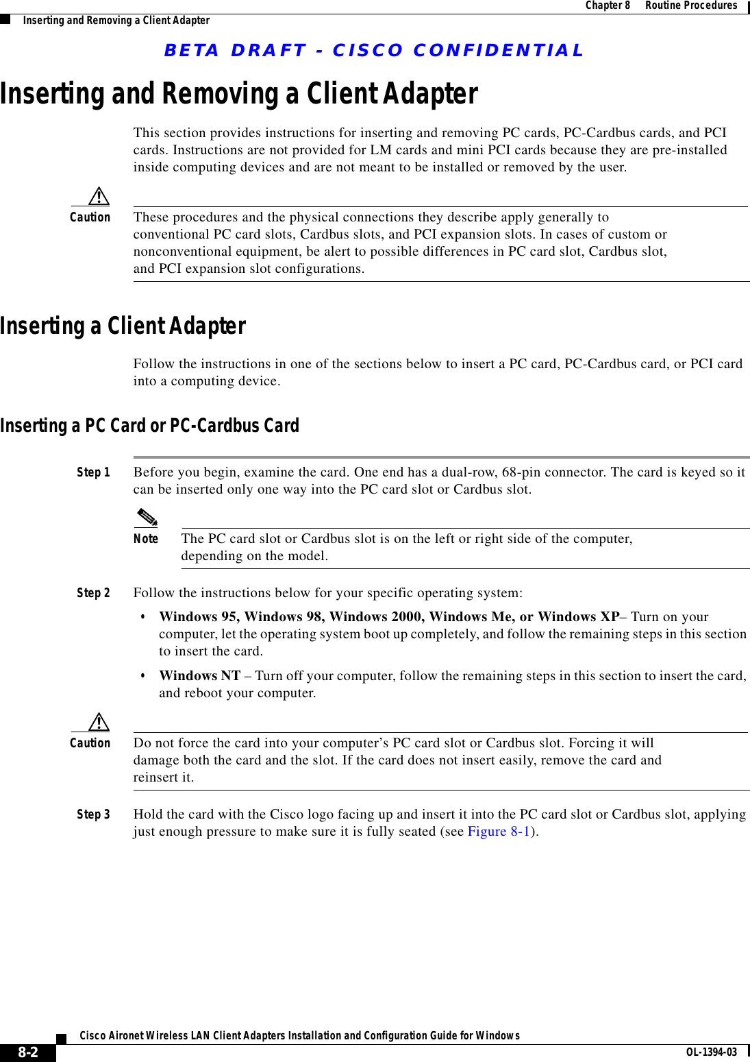
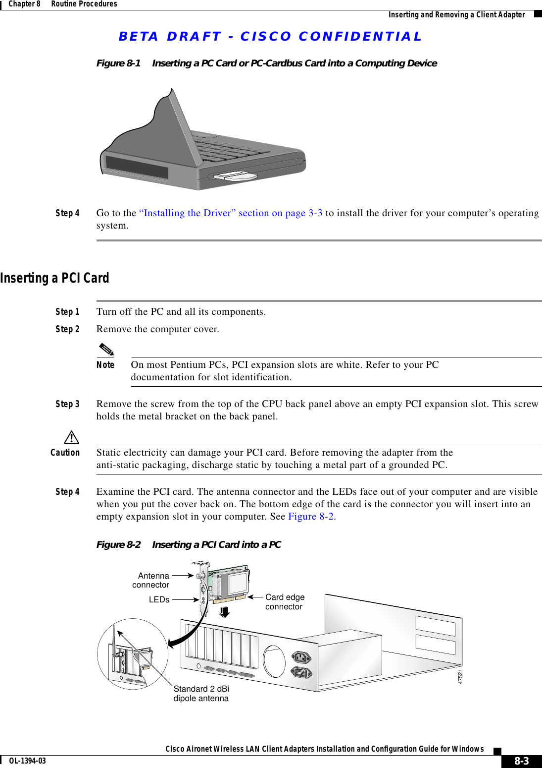
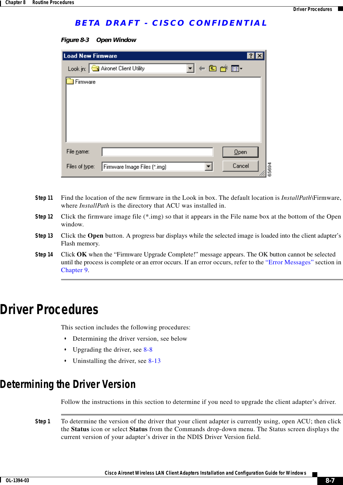
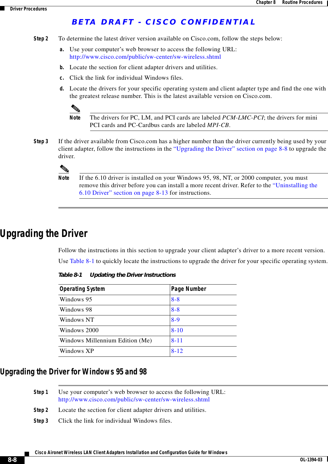
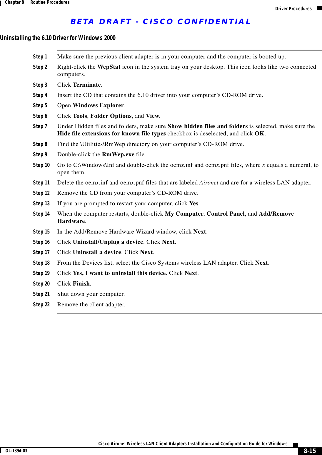
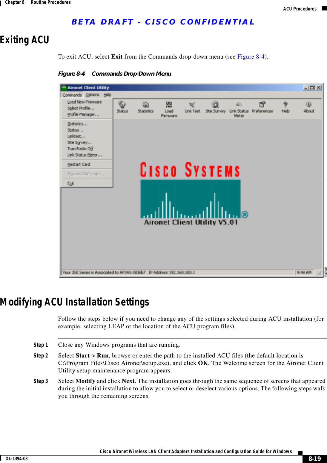
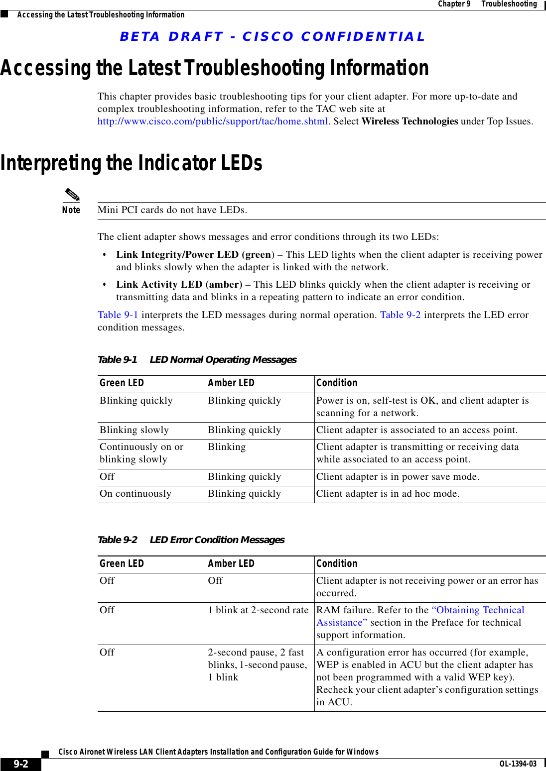
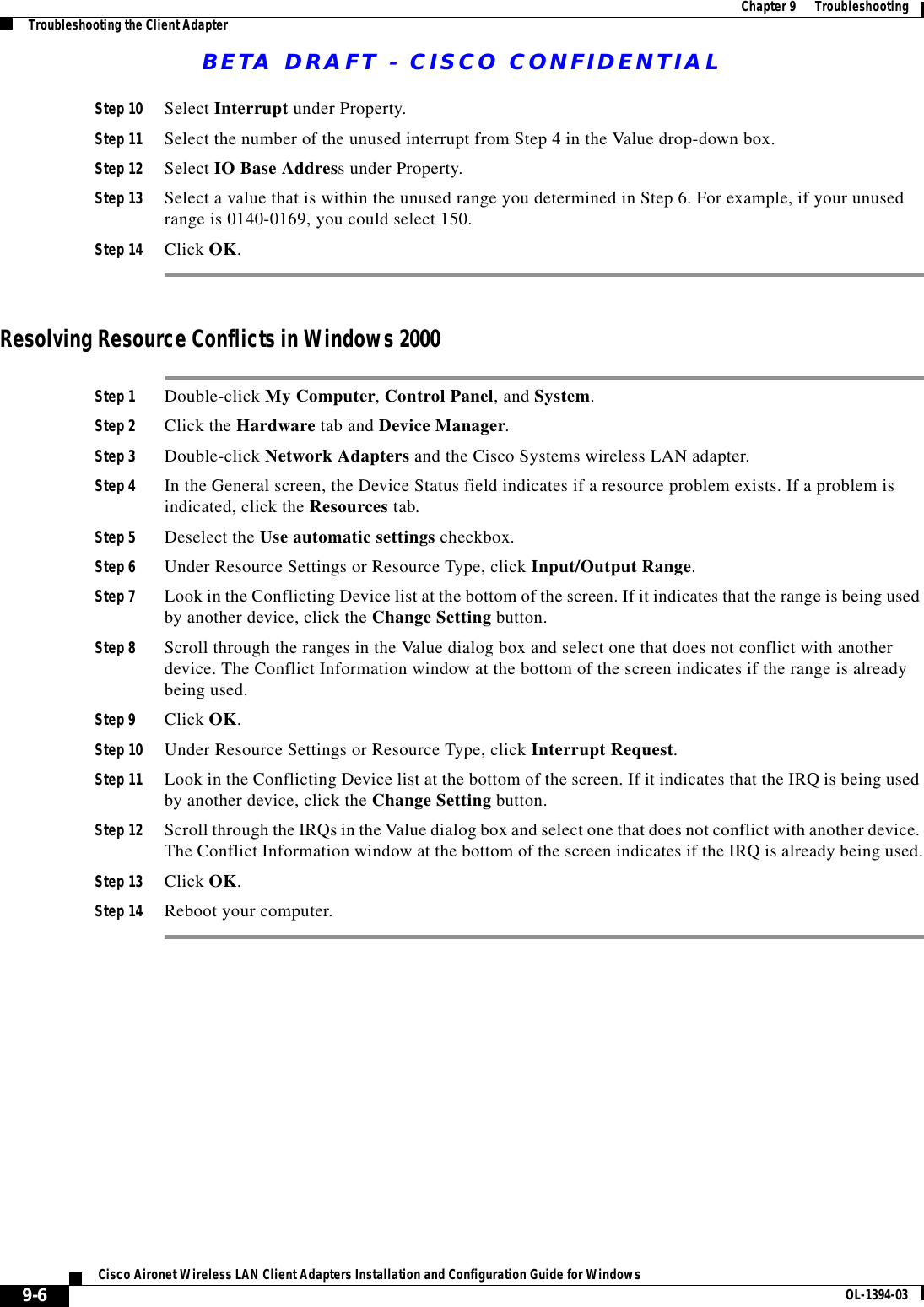
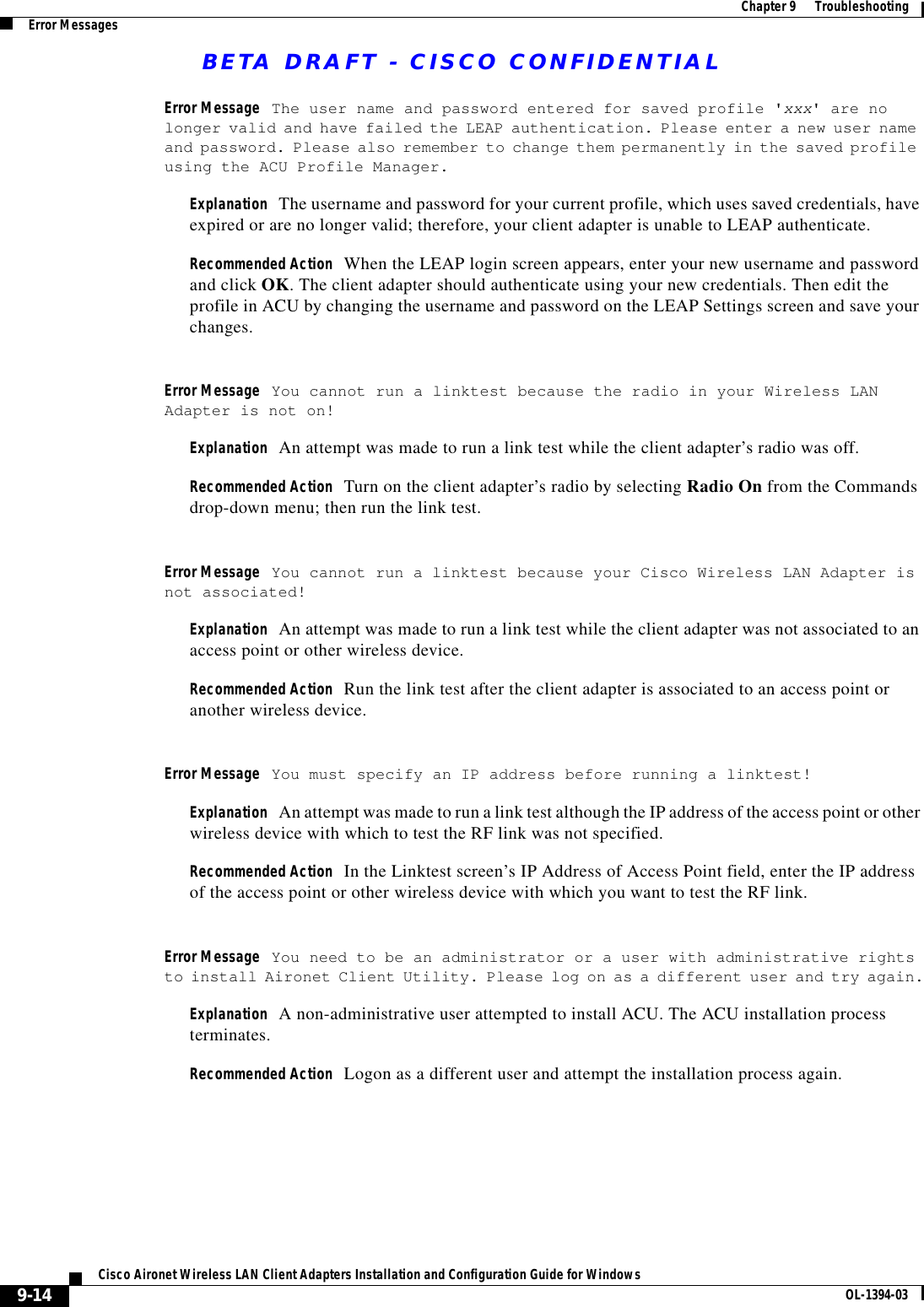
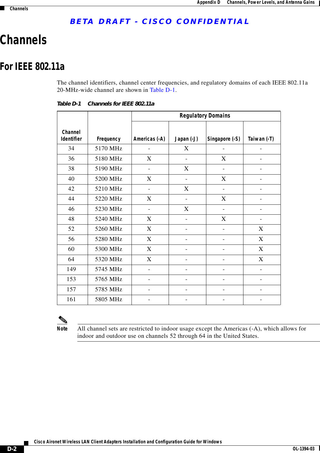
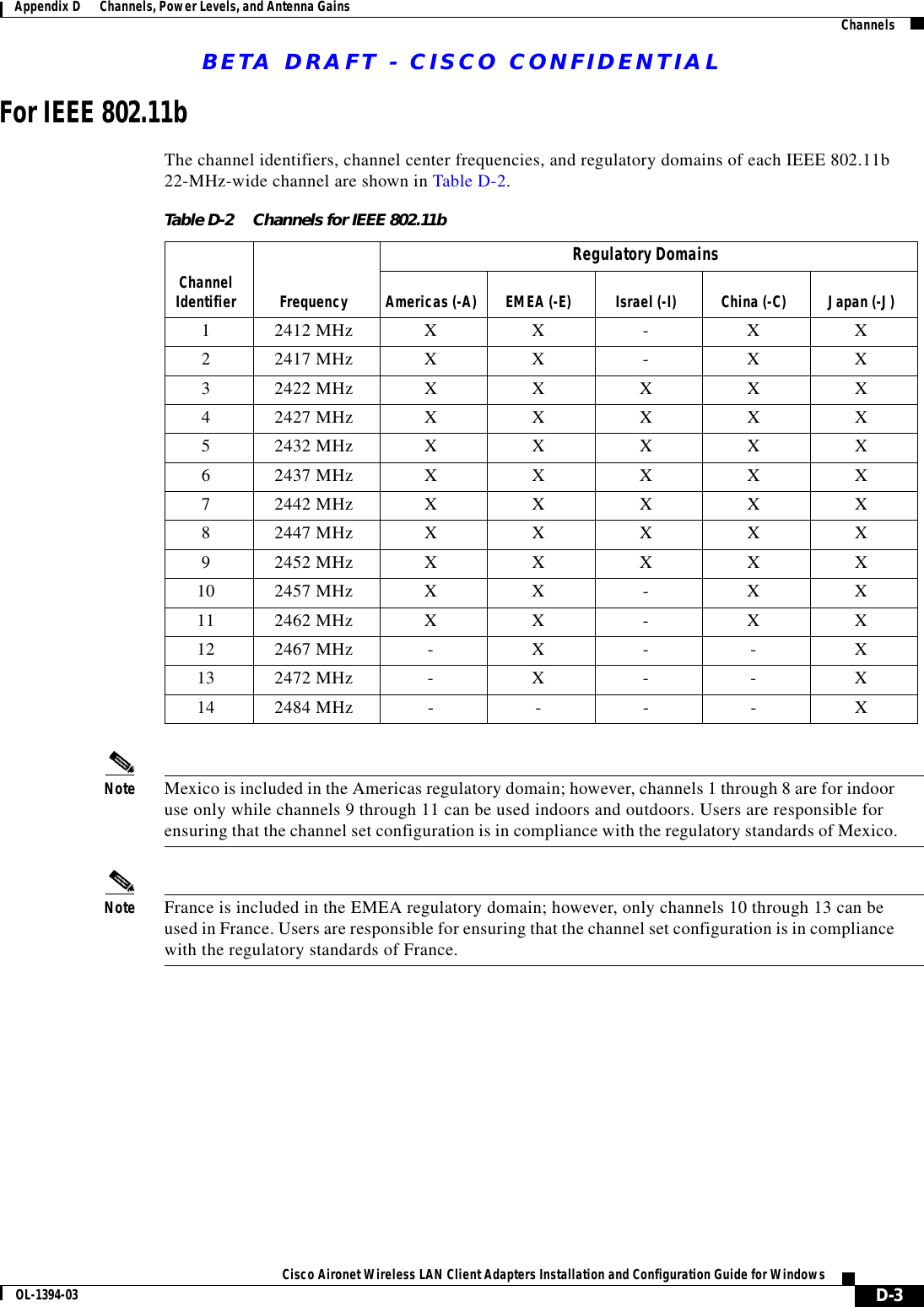
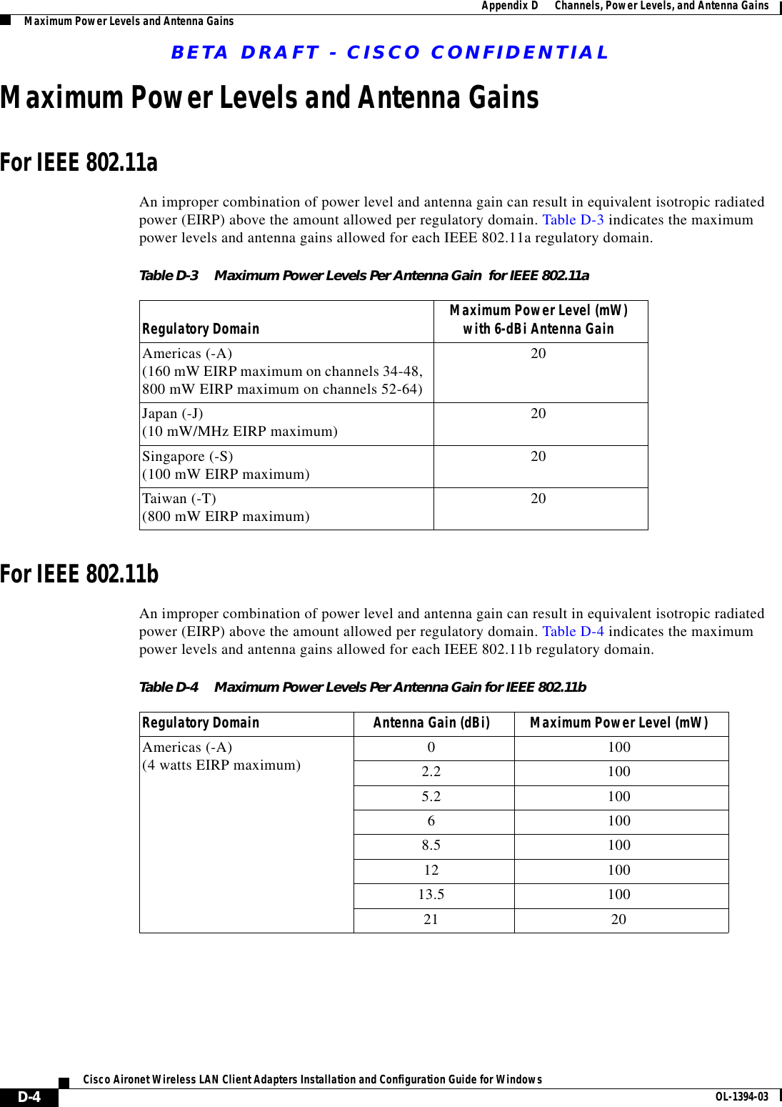
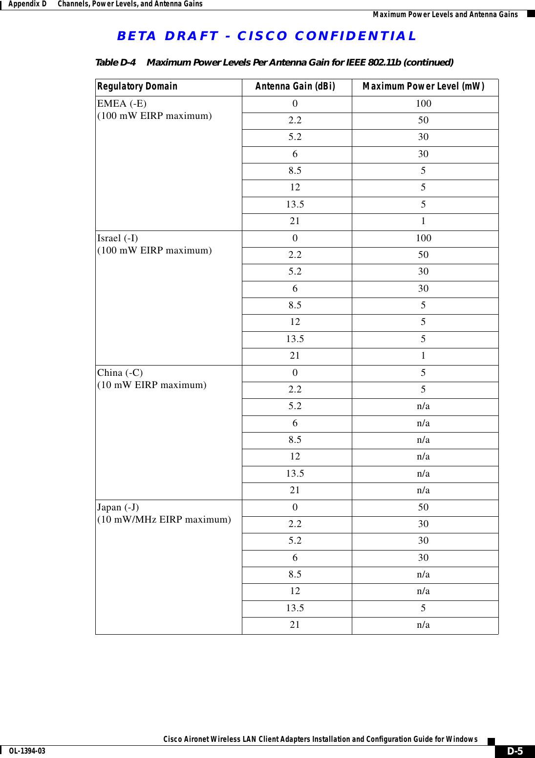
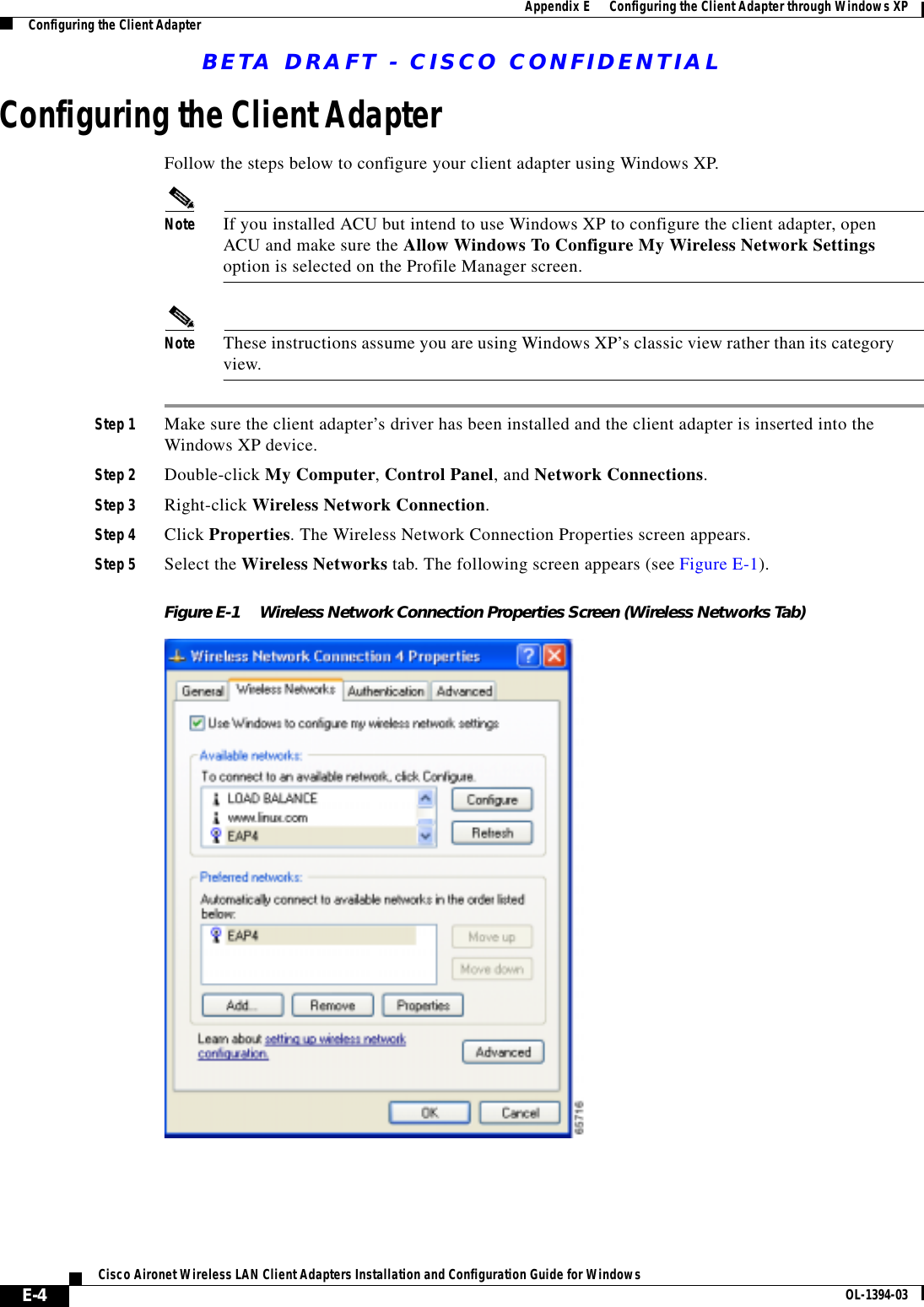
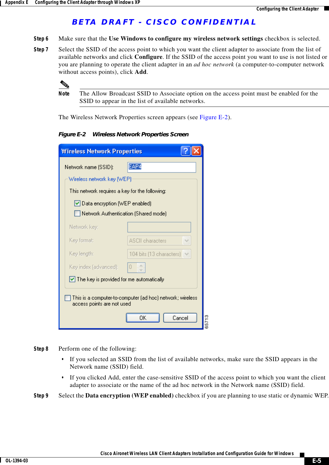
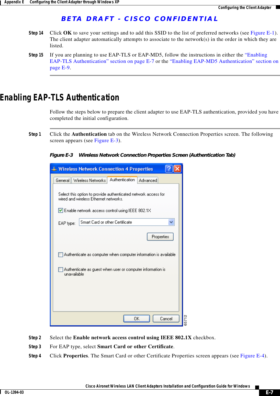
![BETA DRAFT - CISCO CONFIDENTIAL8-18Cisco Aironet Wireless LAN Client Adapters Installation and Configuration Guide for Windows OL-1394-03Chapter 8 Routine ProceduresACU ProceduresUninstalling the Driver for Windows XPNote This procedure will not uninstall the driver that was bundled with Windows XP. It will uninstall only drivers to which you have upgraded. When you follow the steps below to uninstall an upgraded driver and then eject and reinsert the card, Windows finds the original driver and reinstalls it automatically.Note These instructions assume you are using Windows XP’s classic view rather than its category view.Step 1 Double-click My Computer, Control Panel, and System.Step 2 Click the Hardware tab and Device Manager.Step 3 Double-click Network Adapters and Cisco Systems 3x0 Series Wireless LAN Adapter.Step 4 Click the Driver tab and the Uninstall button.Step 5 A warning appears indicating that you are about to uninstall the client adapter from your system. Click OK.ACU ProceduresThis section provides instructions for the following procedures:•Opening ACU, see below•Exiting ACU, see 8-19•Modifying ACU installation settings, see 8-19•Determining the version of ACU, see 8-21•Upgrading ACU, see 8-22•Uninstalling ACU, see 8-24•Deleting the ACU icon from the desktop, see 8-25Opening ACUTo open ACU, perform one of the following:•Double-click the Aironet Client Utility (ACU) icon on your desktop.•Select Aironet Client Utility (ACU) from the folder in the Windows Start Menu that you chose during installation [the default location is Start > Program Files > Cisco Aironet > Aironet Client Utility (ACU)].•Double-click My Computer > Control Panel > Aironet Client Utility.](https://usermanual.wiki/Cisco-Systems/102044.User-Manual-Part-2/User-Guide-249735-Page-18.png)