Cisco Systems 102044 AIR-CB20A-A-K9 User Manual winincfgb
Cisco Systems Inc AIR-CB20A-A-K9 winincfgb
Contents
- 1. User Manual Part 1
- 2. User Manual Part 2
User Manual Part 2

CHAPTER
8-1
Cisco Aironet Wireless LAN Client Adapters Installation and Configuration Guide for Windows
OL-1394-03
8
Routine Procedures
This chapter provides procedures for common tasks related to the client adapter.
The following topics are covered in this chapter:
•Inserting and Removing a Client Adapter, page 8-2
•Upgrading the Firmware, page 8-5
•Driver Procedures, page 8-7
•ACU Procedures, page 8-18
•Restarting the Client Adapter, page 8-25
•Turning Your Client Adapter’s Radio On or Off, page 8-25
•Uninstalling Microsoft Hot Fixes, page 8-26

BETA DRAFT - CISCO CONFIDENTIAL
8-2
Cisco Aironet Wireless LAN Client Adapters Installation and Configuration Guide for Windows OL-1394-03
Chapter 8 Routine Procedures
Inserting and Removing a Client Adapter
Inserting and Removing a Client Adapter
This section provides instructions for inserting and removing PC cards, PC-Cardbus cards, and PCI
cards. Instructions are not provided for LM cards and mini PCI cards because they are pre-installed
inside computing devices and are not meant to be installed or removed by the user.
Caution These procedures and the physical connections they describe apply generally to
conventional PC card slots, Cardbus slots, and PCI expansion slots. In cases of custom or
nonconventional equipment, be alert to possible differences in PC card slot, Cardbus slot,
and PCI expansion slot configurations.
Inserting a Client Adapter
Follow the instructions in one of the sections below to insert a PC card, PC-Cardbus card, or PCI card
into a computing device.
Inserting a PC Card or PC-Cardbus Card
Step 1 Before you begin, examine the card. One end has a dual-row, 68-pin connector. The card is keyed so it
can be inserted only one way into the PC card slot or Cardbus slot.
Note The PC card slot or Cardbus slot is on the left or right side of the computer,
depending on the model.
Step 2 Follow the instructions below for your specific operating system:
•Windows 95, Windows 98, Windows 2000, Windows Me, or Windows XP– Turn on your
computer, let the operating system boot up completely, and follow the remaining steps in this section
to insert the card.
•Windows NT – Turn off your computer, follow the remaining steps in this section to insert the card,
and reboot your computer.
Caution Do not force the card into your computer’s PC card slot or Cardbus slot. Forcing it will
damage both the card and the slot. If the card does not insert easily, remove the card and
reinsert it.
Step 3 Hold the card with the Cisco logo facing up and insert it into the PC card slot or Cardbus slot, applying
just enough pressure to make sure it is fully seated (see Figure 8-1).
BETA DRAFT - CISCO CONFIDENTIAL
8-3
Cisco Aironet Wireless LAN Client Adapters Installation and Configuration Guide for Windows
OL-1394-03
Chapter 8 Routine Procedures Inserting and Removing a Client Adapter
Figure 8-1 Inserting a PC Card or PC-Cardbus Card into a Computing Device
Step 4 Go to the “Installing the Driver” section on page 3-3 to install the driver for your computer’s operating
system.
Inserting a PCI Card
Step 1 Turn off the PC and all its components.
Step 2 Remove the computer cover.
Note On most Pentium PCs, PCI expansion slots are white. Refer to your PC
documentation for slot identification.
Step 3 Remove the screw from the top of the CPU back panel above an empty PCI expansion slot. This screw
holds the metal bracket on the back panel.
Caution Static electricity can damage your PCI card. Before removing the adapter from the
anti-static packaging, discharge static by touching a metal part of a grounded PC.
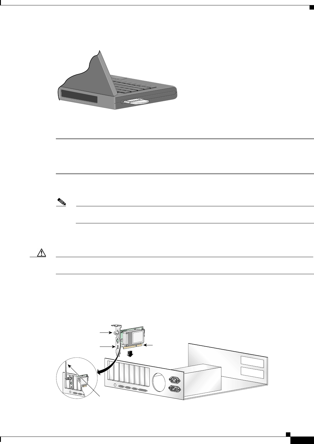
Step 4 Examine the PCI card. The antenna connector and the LEDs face out of your computer and are visible
when you put the cover back on. The bottom edge of the card is the connector you will insert into an
empty expansion slot in your computer. See Figure 8-2.
Figure 8-2 Inserting a PCI Card into a PC
Antenna
connector
LEDs Card edge
connector
Standard 2 dBi
dipole antenna
47521

BETA DRAFT - CISCO CONFIDENTIAL
8-4
Cisco Aironet Wireless LAN Client Adapters Installation and Configuration Guide for Windows OL-1394-03
Chapter 8 Routine Procedures
Inserting and Removing a Client Adapter
Step 5 Tilt the card to allow the antenna connector and LEDs to slip through the opening in the CPU back panel.
Step 6 Press the card into the empty slot until the connector is firmly seated.
Caution Do not force the card into the expansion slot as this could damage both the card and the
slot. If the card does not insert easily, remove it and reinsert it.
Step 7 Reinstall the screw on the CPU back panel and replace the computer cover.
Step 8 Attach the 2-dBi antenna to the card’s antenna connector until it is finger-tight. Do not overtighten.
Step 9 For optimal reception, position the antenna so it is straight up.
Step 10 Boot up your PC.
Removing a Client Adapter
Follow the instructions in one of the sections below to remove a PC card, PC-Cardbus card, or PCI card
from a computing device, when necessary.
Removing a PC Card or PC-Cardbus Card
To remove a PC card or PC-Cardbus card after it is successfully installed and configured (such as when
your laptop is to be transported), completely shut down your computer and pull the card directly out of
the PC card slot or Cardbus slot. When the card is reinserted and the computer is rebooted, your
connection to the network should be re-established.
Removing a PCI Card
Because PCI client adapters are installed inside desktop computers, which are not designed for portable
use, you should have little reason to remove the adapter. However, instructions are provided below in
case you ever need to remove your PCI card.
Step 1 Completely shut down your computer.
Step 2 Disconnect the client adapter’s antenna.
Step 3 Remove the computer cover.
Step 4 Remove the screw from the top of the CPU back panel above the PCI expansion slot that holds your client
adapter.
Step 5 Pull up firmly on the client adapter to release it from the slot and carefully tilt the adapter to allow it to
clear the opening in the CPU back panel.
Step 6 Reinstall the screw on the CPU back panel and replace the computer cover.

BETA DRAFT - CISCO CONFIDENTIAL
8-5
Cisco Aironet Wireless LAN Client Adapters Installation and Configuration Guide for Windows
OL-1394-03
Chapter 8 Routine Procedures Upgrading the Firmware
Upgrading the Firmware
The client adapter is shipped with the firmware installed in its Flash memory; however, a more recent
version of the firmware may be available from Cisco.com. Cisco recommends using the most current
version of radio firmware. Follow the instructions in this section to determine the version of your client
adapter’s firmware and to upgrade it if a more recent version is available from Cisco.com.
Determining the Firmware Version
Follow the instructions in this section to determine if you need to upgrade the client adapter’s firmware.
Step 1 To determine the version of firmware that your client adapter is currently using, open ACU; then click
the Status icon or select Status from the Commands drop-down menu. The Status screen displays the
current version of your adapter’s firmware in the Firmware Version field.
Step 2 To determine the latest firmware version available on Cisco.com, follow the steps below:
a. Use your computer’s web browser to access the following URL:
http://www.cisco.com/public/sw-center/sw-wireless.shtml
b. Locate the section for client adapter firmware.
c. Click the link for your client adapter’s series (for example, 350 Series).
d. Locate the firmware for your client adapter type and find the one with the greatest release number.
This is the latest available version on Cisco.com.
Note The firmware for PC, LM, and PCI cards is labeled PCM-LMC-PCI, the firmware for
mini PCI cards is labeled mini PCI or MPI, and the firmware for PC-Cardbus cards is
labeled CB.
Note In order to use LEAP authentication, your client adapter and access point firmware must
have matching 802.1X draft standards. That is, if the access point uses draft 8 firmware
(prior to 11.06) or has draft 8 selected, the client adapter must use draft 8 firmware (prior
to 4.25.x). Similarly, if the access point uses draft 10 firmware (11.06 or later) and has
draft 10 selected, the client adapter must use draft 10 firmware (4.25.x or later). Mini PCI
card firmware and PC-Cardbus card firmware were first released at draft 10.
Note In order to use EAP-TLS or EAP-MD5 authentication with Windows XP, your client
adapter and access point must use 802.1X draft standard 10 firmware.
Step 3 If the firmware available from Cisco.com has a higher number than the firmware currently installed in
your client adapter, follow the instructions in the “Loading New Firmware” section below to upgrade the
firmware.

BETA DRAFT - CISCO CONFIDENTIAL
8-6
Cisco Aironet Wireless LAN Client Adapters Installation and Configuration Guide for Windows OL-1394-03
Chapter 8 Routine Procedures
Upgrading the Firmware
Loading New Firmware
Caution If a power failure occurs while you are loading new firmware, your client adapter may
become inoperable. If this occurs, follow the instructions in the “Technical Assistance
Center” section of the Preface to contact TAC for assistance.
Follow the instructions below to load new firmware into your client adapter.
Step 1 Use your computer’s web browser to access the following URL:
http://www.cisco.com/public/sw-center/sw-wireless.shtml
Step 2 Locate the section for client adapter firmware.
Step 3 Click the link for your client adapter’s series (for example, 350 Series).
Step 4 Click the latest radio firmware file for your client adapter type.
Note The firmware for PC, LM, and PCI cards is labeled PCM-LMC-PCI, the firmware for mini
PCI cards is labeled mini PCI or MPI, and the firmware for PC-Cardbus cards is labeled CB.
Note If your wireless network uses LEAP authentication, remember to select radio firmware of the
same draft standard as the access points to which your client adapter will be authenticating.
Mini PCI card firmware and PC-Cardbus card firmware were first released at draft 10.
Note If your wireless network uses EAP-TLS or EAP-MD5 authentication, remember to select
draft 10 of the radio firmware.
Step 5 Read and accept the terms and conditions of the Software License Agreement.
Step 6 Select the firmware file to download it.
Step 7 Save the file to a floppy disk or to your computer’s hard drive.
Step 8 Locate the file using Windows Explorer, double-click it, and extract the image file to a folder.
Step 9 Make sure the client adapter is installed in your computer and is operational.
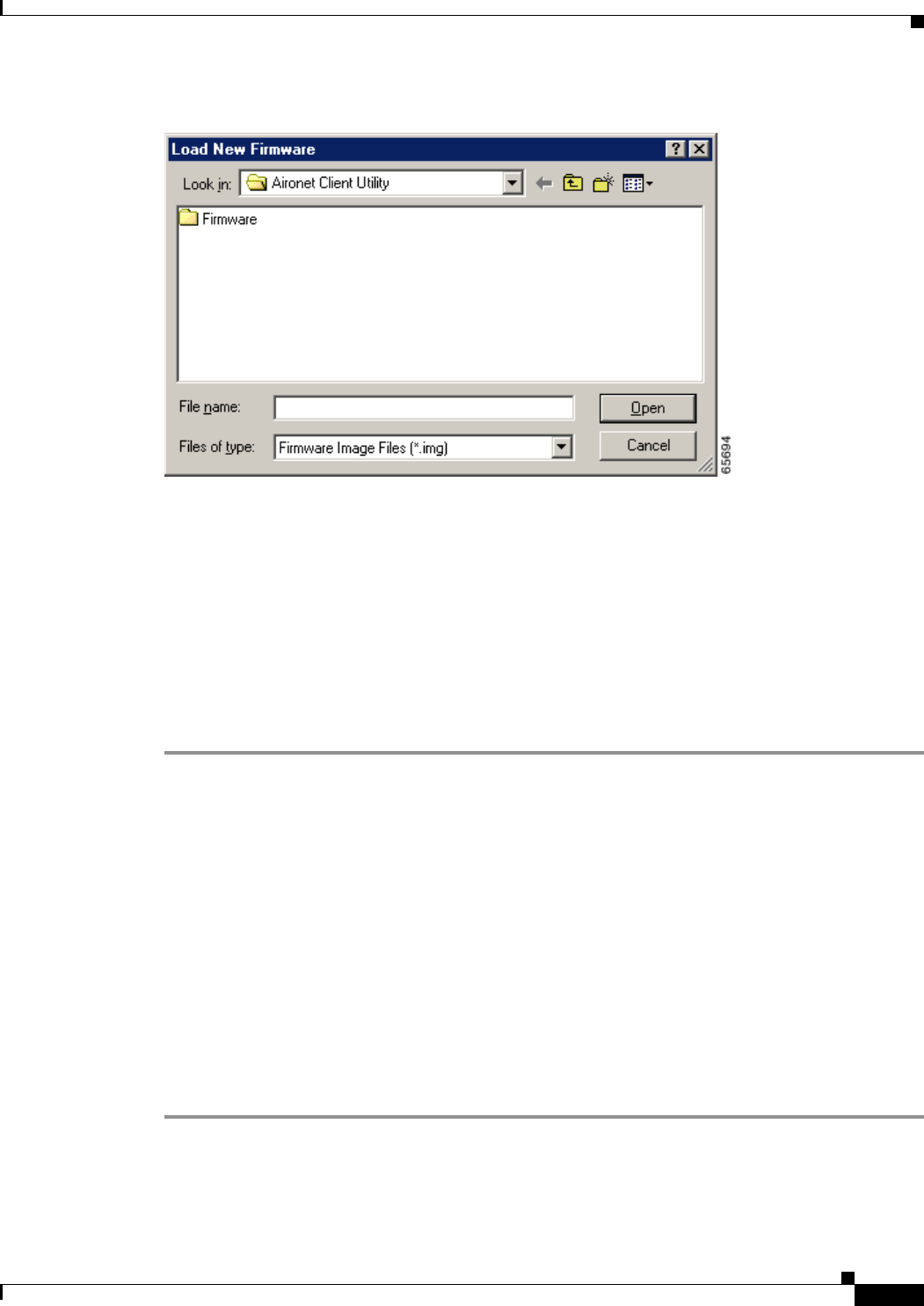
Step 10 Open ACU; then click the Load Firmware icon or select Load New Firmware from the Commands
drop-down menu. The Open window appears (see Figure 8-3).
BETA DRAFT - CISCO CONFIDENTIAL
8-7
Cisco Aironet Wireless LAN Client Adapters Installation and Configuration Guide for Windows
OL-1394-03
Chapter 8 Routine Procedures Driver Procedures
Figure 8-3 Open Window
Step 11 Find the location of the new firmware in the Look in box. The default location is InstallPath\Firmware,
where InstallPath is the directory that ACU was installed in.
Step 12 Click the firmware image file (*.img) so that it appears in the File name box at the bottom of the Open
window.
Step 13 Click the Open button. A progress bar displays while the selected image is loaded into the client adapter’s
Flash memory.
Step 14 Click OK when the “Firmware Upgrade Complete!” message appears. The OK button cannot be selected
until the process is complete or an error occurs. If an error occurs, refer to the “Error Messages” section in
Chapter 9.
Driver Procedures
This section includes the following procedures:
•Determining the driver version, see below
•Upgrading the driver, see 8-8
•Uninstalling the driver, see 8-13
Determining the Driver Version
Follow the instructions in this section to determine if you need to upgrade the client adapter’s driver.
Step 1 To determine the version of the driver that your client adapter is currently using, open ACU; then click
the Status icon or select Status from the Commands drop-down menu. The Status screen displays the
current version of your adapter’s driver in the NDIS Driver Version field.

BETA DRAFT - CISCO CONFIDENTIAL
8-8
Cisco Aironet Wireless LAN Client Adapters Installation and Configuration Guide for Windows OL-1394-03
Chapter 8 Routine Procedures
Driver Procedures
Step 2 To determine the latest driver version available on Cisco.com, follow the steps below:
a. Use your computer’s web browser to access the following URL:
http://www.cisco.com/public/sw-center/sw-wireless.shtml
b. Locate the section for client adapter drivers and utilities.
c. Click the link for individual Windows files.
d. Locate the drivers for your specific operating system and client adapter type and find the one with
the greatest release number. This is the latest available version on Cisco.com.
Note The drivers for PC, LM, and PCI cards are labeled PCM-LMC-PCI; the drivers for mini
PCI cards and PC-Cardbus cards are labeled MPI-CB.
Step 3 If the driver available from Cisco.com has a higher number than the driver currently being used by your
client adapter, follow the instructions in the “Upgrading the Driver” section on page 8-8 to upgrade the
driver.
Note If the 6.10 driver is installed on your Windows 95, 98, NT, or 2000 computer, you must
remove this driver before you can install a more recent driver. Refer to the “Uninstalling the
6.10 Driver” section on page 8-13 for instructions.
Upgrading the Driver
Follow the instructions in this section to upgrade your client adapter’s driver to a more recent version.
Use Table 8-1 to quickly locate the instructions to upgrade the driver for your specific operating system.
Upgrading the Driver for Windows 95 and 98
Step 1 Use your computer’s web browser to access the following URL:
http://www.cisco.com/public/sw-center/sw-wireless.shtml
Step 2 Locate the section for client adapter drivers and utilities.
Step 3 Click the link for individual Windows files.
Table 8-1 Updating the Driver Instructions
Operating System Page Number
Windows 95 8-8
Windows 98 8-8
Windows NT 8-9
Windows 2000 8-10
Windows Millennium Edition (Me) 8-11
Windows XP 8-12

BETA DRAFT - CISCO CONFIDENTIAL
8-9
Cisco Aironet Wireless LAN Client Adapters Installation and Configuration Guide for Windows
OL-1394-03
Chapter 8 Routine Procedures Driver Procedures
Step 4 Select the latest driver file for Windows 95 or Windows 98 and your client adapter type.
Note The drivers for PC, LM, and PCI cards are labeled PCM-LMC-PCI; the drivers for mini PCI
cards and PC-Cardbus cards are labeled MPI-CB.
Step 5 Read and accept the terms and conditions of the Software License Agreement.
Step 6 Select the driver file to download it.
Step 7 Save the file to a floppy disk or to your computer’s hard drive.
Step 8 Locate the file using Windows Explorer, double-click it, and extract its files to a folder.
Step 9 Make sure your client adapter is installed in your computer.
Step 10 Double-click My Computer, Control Panel, and System.
Step 11 Click the Device Manager tab.
Step 12 Double-click Network Adapters.
Step 13 Select the Cisco Systems wireless LAN adapter.
Step 14 Click Properties, the Driver tab, and the Change Driver or Update Driver button.
Step 15 The Update Device Driver Wizard window appears. Click Next.
Step 16 Select Search for a better driver than the one your device is using now (Recommended) and click
Next.
Step 17 Select the location of the new driver (floppy disk drive or specify a location), deselect the other options,
enter the full path to where you extracted the files, and click Next.
Step 18 A message appears indicating that the system is ready to install the new driver. Click Next and Finish.
The driver upgrade is complete, and the old driver is overwritten by the new one.
Upgrading the Driver for Windows NT
Step 1 Use your computer’s web browser to access the following URL:
http://www.cisco.com/public/sw-center/sw-wireless.shtml
Step 2 Locate the section for client adapter drivers and utilities.
Step 3 Click the link for individual Windows files.
Step 4 Select the latest driver file for Windows NT and your client adapter type.
Note The drivers for PC, LM, and PCI cards are labeled PCM-LMC-PCI; the drivers for mini PCI
cards and PC-Cardbus cards are labeled MPI-CB.
Step 5 Read and accept the terms and conditions of the Software License Agreement.
Step 6 Select the driver file to download it.
Step 7 Save the file to a floppy disk or to your computer’s hard drive.
Step 8 Locate the file using Windows Explorer, double-click it, and extract its files to a folder.
Step 9 Make sure your client adapter is installed in your computer.

BETA DRAFT - CISCO CONFIDENTIAL
8-10
Cisco Aironet Wireless LAN Client Adapters Installation and Configuration Guide for Windows OL-1394-03
Chapter 8 Routine Procedures
Driver Procedures
Step 10 Double-click My Computer, Control Panel, Network, and Adapters.
Step 11 Select the Cisco Systems wireless LAN adapter.
Step 12 Click the Update button.
Step 13 In the Windows NT Setup window, enter the path to where you extracted the files and click Continue.
Step 14 Follow the instructions on the screen to complete the upgrade process.
Upgrading the Driver for Windows 2000
Step 1 Use your computer’s web browser to access the following URL:
http://www.cisco.com/public/sw-center/sw-wireless.shtml
Step 2 Locate the section for client adapter drivers and utilities.
Step 3 Click the link for individual Windows files.
Step 4 Select the latest driver file for Windows 2000 and your client adapter type.
Note The drivers for PC, LM, and PCI cards are labeled PCM-LMC-PCI; the drivers for mini PCI
cards and PC-Cardbus cards are labeled MPI-CB.
Step 5 Read and accept the terms and conditions of the Software License Agreement.
Step 6 Select the driver file to download it.
Step 7 Save the file to a floppy disk or to your computer’s hard drive.
Step 8 Locate the file using Windows Explorer, double-click it, and extract its files to a folder.
Step 9 Make sure your client adapter is installed in your computer.
Step 10 Double-click My Computer, Control Panel, and System.
Step 11 Click the Hardware tab and Device Manager.
Step 12 Double-click Network Adapters and the Cisco Systems wireless LAN adapter.
Step 13 Click the Driver tab.
Step 14 Click the Update Driver button.
Step 15 The Update Device Driver Wizard window appears. Click Next.
Step 16 Select Display a list of the known drivers for this device so that I can choose a specific driver and
click Next.
Step 17 Click Have Disk.
Step 18 Enter or browse to the path where you extracted the files and click OK.
Step 19 A message appears indicating that the system is ready to install the new driver. Click Next and Finish.
The driver upgrade is complete, and the old driver is overwritten by the new one.

BETA DRAFT - CISCO CONFIDENTIAL
8-11
Cisco Aironet Wireless LAN Client Adapters Installation and Configuration Guide for Windows
OL-1394-03
Chapter 8 Routine Procedures Driver Procedures
Upgrading the Driver for Windows Me
Step 1 Use your computer’s web browser to access the following URL:
http://www.cisco.com/public/sw-center/sw-wireless.shtml
Step 2 Locate the section for client adapter drivers and utilities.
Step 3 Click the link for individual Windows files.
Step 4 Select the latest driver file for Windows Me and your client adapter type.
Note The drivers for PC, LM, and PCI cards are labeled PCM-LMC-PCI; the drivers for mini PCI
cards and PC-Cardbus cards are labeled MPI-CB.
Step 5 Read and accept the terms and conditions of the Software License Agreement.
Step 6 Select the driver file to download it.
Step 7 Save the file to a floppy disk or to your computer’s hard drive.
Step 8 Locate the file using Windows Explorer, double-click it, and extract its files to a folder.
Step 9 Make sure your client adapter is installed in your computer.
Step 10 Double-click My Computer, Control Panel, and System.
Step 11 Click the Device Manager tab.
Step 12 Double-click Network Adapters.
Step 13 Select the Cisco Systems wireless LAN adapter.
Step 14 Click Properties, the Driver tab, and the Update Driver button. The Update Device Driver Wizard
window appears.
Step 15 Select Specify the location of the driver (Advanced) and click Next.
Step 16 Select Search for a better driver than the one your device is using now (Recommended).
Step 17 Select the Specify a location checkbox, deselect the other options, enter the path to where you extracted
the files, and click Next.
Step 18 A message appears indicating that Windows has found an updated driver. Select The updated driver
(Recommended) and click Next.
Step 19 A message appears indicating that the system is ready to install the new driver. Click Next and Finish.
Step 20 If you are prompted to restart your computer, click Yes.
The driver upgrade is complete, and the old driver is overwritten by the new one.

BETA DRAFT - CISCO CONFIDENTIAL
8-12
Cisco Aironet Wireless LAN Client Adapters Installation and Configuration Guide for Windows OL-1394-03
Chapter 8 Routine Procedures
Driver Procedures
Upgrading the Driver for Windows XP
Note These instructions assume you are using Windows XP’s classic view rather than its category
view.
Step 1 Use your computer’s web browser to access the following URL:
http://www.cisco.com/public/sw-center/sw-wireless.shtml
Step 2 Locate the section for client adapter drivers and utilities.
Step 3 Click the link for individual Windows files.
Step 4 Select the latest driver file for Windows XP and your client adapter type.
Note The drivers for PC, LM, and PCI cards are labeled PCM-LMC-PCI; the drivers for mini PCI
cards and PC-Cardbus cards are labeled MPI-CB.
Step 5 Read and accept the terms and conditions of the Software License Agreement.
Step 6 Select the driver file to download it.
Step 7 Save the file to a floppy disk or to your computer’s hard drive.
Step 8 Locate the file using Windows Explorer, double-click it, and extract its files to a folder.
Step 9 Make sure your client adapter is installed in your computer.
Step 10 Double-click My Computer, Control Panel, and System.
Step 11 Click the Hardware tab and Device Manager.
Step 12 Double-click Network Adapters and Cisco Systems 3x0 Series Wireless LAN Adapter.
Step 13 Click the Driver tab and the Update Driver button. The Welcome to the Hardware Update Wizard
screen appears.
Step 14 Select the Install from a list or specific location (Advanced) option and click Next.
Step 15 When prompted to choose your search and installation options, select Don’t search. I will choose the
driver to install and click Next.
Step 16 When prompted to select a network adapter to install, click the Have Disk button. The Install From Disk
screen appears.
Step 17 Click the Browse button, browse to the location where you extracted the files, and click Open. The
installation wizard finds the driver file (netx500.inf). Click OK on the Install From Disk screen.
Step 18 The Select Network Adapter screen reappears. Select the Cisco Systems wireless LAN adapter and click
Next.
Step 19 The installation wizard copies the driver files from the floppy disk or computer’s hard drive. When the
installation is complete, click Finish.
The driver upgrade is complete, and the old driver is overwritten by the new one.

BETA DRAFT - CISCO CONFIDENTIAL
8-13
Cisco Aironet Wireless LAN Client Adapters Installation and Configuration Guide for Windows
OL-1394-03
Chapter 8 Routine Procedures Driver Procedures
Uninstalling the Driver
This section provides instructions for uninstalling a client adapter driver from your computer. Two
examples of when you may need to uninstall a driver are listed below:
•If you are running Windows 95, 98, NT, or 2000 and a Cisco Aironet client adapter was previously
installed on your computer with the 6.10 driver, you must uninstall this driver before you can install
a more recent driver, such as the one provided on the CD that shipped with your client adapter.
•If you experience difficulty while installing the driver for your computer’s operating system, you
may want to abort the installation procedure and start over. However, before you attempt to install
the driver again, you must first uninstall any part of the driver that you may have already installed.
Table 8-2 enables you to quickly locate the instructions for uninstalling a driver for your specific
operating system.
Uninstalling the 6.10 Driver
To uninstall the 6.10 driver, follow the instructions that apply to your computer’s operating system.
Uninstalling the 6.10 Driver for Windows 95 and 98
Step 1 Make sure the previous client adapter is in your computer and the computer is booted up.
Step 2 Right-click the WepStat icon in the system tray on your desktop. This icon looks like two connected
computers.
Step 3 Click Terminate.
Step 4 Insert the CD that contains the 6.10 driver into your computer’s CD-ROM drive.
Step 5 Open Windows Explorer and find the \Utilities\RmWep directory on your computer’s CD-ROM drive.
Step 6 Double-click the RmWep.exe file.
Step 7 Minimize Windows Explorer.
Step 8 Double-click My Computer, Control Panel, and Network.
Step 9 In the Network window, select the Cisco Systems wireless LAN adapter.
Step 10 Click Remove and OK.
Step 11 When prompted to restart your computer, click No.
Step 12 Maximize Windows Explorer.
Table 8-2 Locating Driver Uninstall Instructions
Operating System 6.10 Driver Driver Other Than 6.10
Windows 95 page 8-13 page 8-16
Windows 98 page 8-13 page 8-16
Windows NT page 8-14 page 8-17
Windows 2000 page 8-15 page 8-17
Windows Millennium (Me) Not applicable page 8-16
Windows XP Not applicable page 8-18

BETA DRAFT - CISCO CONFIDENTIAL
8-14
Cisco Aironet Wireless LAN Client Adapters Installation and Configuration Guide for Windows OL-1394-03
Chapter 8 Routine Procedures
Driver Procedures
Step 13 Click View, Options or Folder Options, and View. Under Hidden files, make sure Show all files is
selected, make sure the Hide file extensions for known file types checkbox is deselected, and click
OK.
Step 14 Find your computer’s operating system in the following table, go to the path listed, and delete the file
indicated.
Step 15 Remove the CD from your computer’s CD-ROM drive.
Step 16 Shut down your computer.
Step 17 Remove the client adapter.
Uninstalling the 6.10 Driver for Windows NT
Step 1 Make sure the previous client adapter is in your computer and the computer is booted up.
Step 2 Right-click the WepStat icon in the system tray on your desktop. This icon looks like two connected
computers.
Step 3 Click Terminate.
Step 4 Insert the CD that contains the 6.10 driver into your computer’s CD-ROM drive.
Step 5 Open Windows Explorer and find the \Utilities\RmWep directory on your computer’s CD-ROM drive.
Step 6 Double-click the RmWep.exe file.
Step 7 Close Windows Explorer.
Step 8 Double-click My Computer, Control Panel, and Network.
Step 9 In the Network window, click the Adapters tab.
Step 10 Select the Cisco Systems wireless LAN adapter.
Step 11 Click Remove.
Step 12 When asked if you wish to continue, click Yes and Close.
Step 13 When prompted to restart your computer, click No.
Step 14 Remove the CD from your computer’s CD-ROM drive.
Step 15 Shut down your computer.
Step 16 Remove the client adapter.
Operating System Location of File File to be Deleted
Windows 95 C:\Windows\Inf pc4800.inf
Windows 98 C:\Windows\Inf or
C:\Windows\Inf\Other pc4800.inf or
aironetnetx500.inf

BETA DRAFT - CISCO CONFIDENTIAL
8-15
Cisco Aironet Wireless LAN Client Adapters Installation and Configuration Guide for Windows
OL-1394-03
Chapter 8 Routine Procedures Driver Procedures
Uninstalling the 6.10 Driver for Windows 2000
Step 1 Make sure the previous client adapter is in your computer and the computer is booted up.
Step 2 Right-click the WepStat icon in the system tray on your desktop. This icon looks like two connected
computers.
Step 3 Click Terminate.
Step 4 Insert the CD that contains the 6.10 driver into your computer’s CD-ROM drive.
Step 5 Open Windows Explorer.
Step 6 Click Tools, Folder Options, and View.
Step 7 Under Hidden files and folders, make sure Show hidden files and folders is selected, make sure the
Hide file extensions for known file types checkbox is deselected, and click OK.
Step 8 Find the \Utilities\RmWep directory on your computer’s CD-ROM drive.
Step 9 Double-click the RmWep.exe file.
Step 10 Go to C:\Windows\Inf and double-click the oemx.inf and oemx.pnf files, where x equals a numeral, to
open them.
Step 11 Delete the oemx.inf and oemx.pnf files that are labeled Aironet and are for a wireless LAN adapter.
Step 12 Remove the CD from your computer’s CD-ROM drive.
Step 13 If you are prompted to restart your computer, click Yes.
Step 14 When the computer restarts, double-click My Computer, Control Panel, and Add/Remove
Hardware.
Step 15 In the Add/Remove Hardware Wizard window, click Next.
Step 16 Click Uninstall/Unplug a device. Click Next.
Step 17 Click Uninstall a device. Click Next.
Step 18 From the Devices list, select the Cisco Systems wireless LAN adapter. Click Next.
Step 19 Click Yes, I want to uninstall this device. Click Next.
Step 20 Click Finish.
Step 21 Shut down your computer.
Step 22 Remove the client adapter.

BETA DRAFT - CISCO CONFIDENTIAL
8-16
Cisco Aironet Wireless LAN Client Adapters Installation and Configuration Guide for Windows OL-1394-03
Chapter 8 Routine Procedures
Driver Procedures
Uninstalling a Driver Other Than the 6.10 Driver
To uninstall a driver other than the 6.10 driver, follow the instructions that apply to your computer’s
operating system.
Note When you uninstall the driver, any saved profiles are lost.
Uninstalling the Driver for Windows 95, 98, and Me
Note This procedure does not uninstall the driver that was bundled with Windows Me. It uninstalls only
drivers to which you have upgraded. When you follow the steps below to uninstall an upgraded driver
and then eject and reinsert the card, Windows Me finds the original driver and reinstalls it
automatically.
Step 1 Double-click My Computer, Control Panel, and Network.
Step 2 In the Network window, select the Cisco Systems wireless LAN adapter.
Step 3 Click Remove and OK.
Step 4 When prompted to restart your computer, click No.
Step 5 Open Windows Explorer.
Step 6 If your computer’s operating system is Windows 95 or 98, click View, Options or Folder Options, and
View. Under Hidden files, make sure Show all files is selected and click OK.
Step 7 Find your computer’s operating system in the following table, go to the path listed, and delete the file
indicated.
Step 8 Find your computer’s operating system in the following table and delete any pcx50*.sys files from the
path indicated.
Step 9 Restart your computer.
Operating System Location of File File to be Deleted
Windows 98 C:\Windows\Inf or
C:\Windows\Inf\Other pc4800.inf,
aironetnetx500.inf, or
cisconetx500.inf
Windows Me C:\Windows\Inf\Other aironetnetx500.inf or
cisconetx500.inf
Operating System Location of pcx50*.sys Files
Windows 95 C:\Windows\System\pcx50*.sys
Windows 98 C:\Windows\System\pcx50*.sys
Windows Me C:\Windows\System32\Drivers\pcx50*.sys

BETA DRAFT - CISCO CONFIDENTIAL
8-17
Cisco Aironet Wireless LAN Client Adapters Installation and Configuration Guide for Windows
OL-1394-03
Chapter 8 Routine Procedures Driver Procedures
Uninstalling the Driver for Windows NT
Step 1 Double-click My Computer, Control Panel, and Network.
Step 2 In the Network window, click the Adapters tab.
Step 3 Select the Cisco Systems wireless LAN adapter.
Step 4 Click Remove.
Step 5 When asked if you wish to continue, click Yes and Close.
Step 6 When prompted to restart your computer, click Yes.
Uninstalling the Driver for Windows 2000
Step 1 Make sure the client adapter is installed in your computer. Otherwise, Windows cannot find the adapter
to remove it.
Step 2 Double-click My Computer, Control Panel, and Add/Remove Hardware.
Step 3 In the Add/Remove Hardware Wizard window, click Next.
Step 4 Click Uninstall/Unplug a device. Click Next.
Step 5 Click Uninstall a device. Click Next.
Step 6 From the Devices list, select the Cisco Systems wireless LAN adapter. Click Next.
Step 7 Click Yes, I want to uninstall this device. Click Next.
Step 8 Click Finish.
Step 9 Open Windows Explorer.
Step 10 Click Tools, Folder Options, and View.
Step 11 Under Hidden files and folders, make sure Show hidden files and folders is selected. Click OK.
Step 12 Go to C:\Windows\Inf and double-click the oemx.inf and oemx.pnf files, where x equals a numeral, to
open them.
Step 13 Delete the oemx.inf and oemx.pnf files that are labeled Cisco and are for a wireless LAN adapter.
Step 14 Go to C:\Windows\System32\Drivers and delete any pcx500*.sys files.
Step 15 Shut down your computer.
Step 16 Remove the client adapter.
Step 17 Turn your computer back on.

BETA DRAFT - CISCO CONFIDENTIAL
8-18
Cisco Aironet Wireless LAN Client Adapters Installation and Configuration Guide for Windows OL-1394-03
Chapter 8 Routine Procedures
ACU Procedures
Uninstalling the Driver for Windows XP
Note This procedure will not uninstall the driver that was bundled with Windows XP. It will
uninstall only drivers to which you have upgraded. When you follow the steps below to
uninstall an upgraded driver and then eject and reinsert the card, Windows finds the original
driver and reinstalls it automatically.
Note These instructions assume you are using Windows XP’s classic view rather than its category
view.
Step 1 Double-click My Computer, Control Panel, and System.
Step 2 Click the Hardware tab and Device Manager.
Step 3 Double-click Network Adapters and Cisco Systems 3x0 Series Wireless LAN Adapter.
Step 4 Click the Driver tab and the Uninstall button.
Step 5 A warning appears indicating that you are about to uninstall the client adapter from your system. Click
OK.
ACU Procedures
This section provides instructions for the following procedures:
•Opening ACU, see below
•Exiting ACU, see 8-19
•Modifying ACU installation settings, see 8-19
•Determining the version of ACU, see 8-21
•Upgrading ACU, see 8-22
•Uninstalling ACU, see 8-24
•Deleting the ACU icon from the desktop, see 8-25
Opening ACU
To open ACU, perform one of the following:
•Double-click the Aironet Client Utility (ACU) icon on your desktop.
•Select Aironet Client Utility (ACU) from the folder in the Windows Start Menu that you chose
during installation [the default location is Start > Program Files > Cisco Aironet > Aironet Client
Utility (ACU)].
•Double-click My Computer > Control Panel > Aironet Client Utility.
BETA DRAFT - CISCO CONFIDENTIAL
8-19
Cisco Aironet Wireless LAN Client Adapters Installation and Configuration Guide for Windows
OL-1394-03
Chapter 8 Routine Procedures ACU Procedures
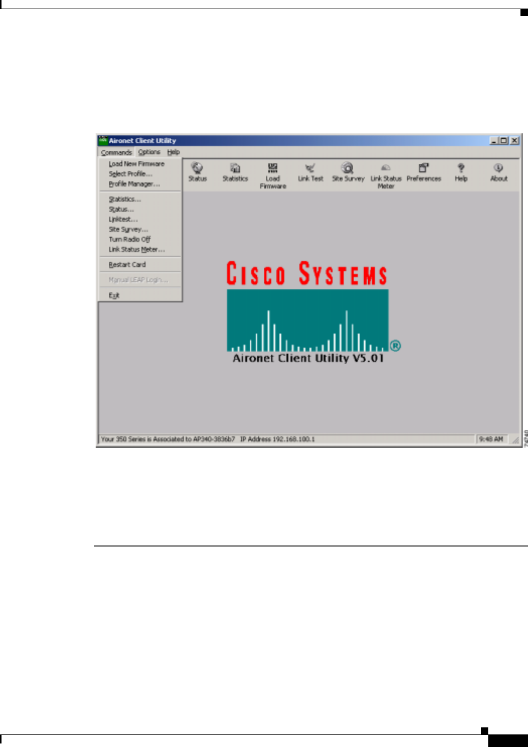
Exiting ACU
To exit ACU, select Exit from the Commands drop-down menu (see Figure 8-4).
Figure 8-4 Commands Drop-Down Menu
Modifying ACU Installation Settings
Follow the steps below if you need to change any of the settings selected during ACU installation (for
example, selecting LEAP or the location of the ACU program files).
Step 1 Close any Windows programs that are running.
Step 2 Select Start > Run, browse or enter the path to the installed ACU files (the default location is
C:\Program Files\Cisco Aironet\setup.exe), and click OK. The Welcome screen for the Aironet Client
Utility setup maintenance program appears.
Step 3 Select Modify and click Next. The installation goes through the same sequence of screens that appeared
during the initial installation to allow you to select or deselect various options. The following steps walk
you through the remaining screens.

BETA DRAFT - CISCO CONFIDENTIAL
8-20
Cisco Aironet Wireless LAN Client Adapters Installation and Configuration Guide for Windows OL-1394-03
Chapter 8 Routine Procedures
ACU Procedures
Step 4 In the Select Options screen, select as many of the following options as desired and click Next:
Step 5 In the Choose Destination Location screen, perform one of the following:
•If you want the ACU program files to be installed in the default location (C:\Program Files, if
C:\Program Files is the default Windows program file folder), click Next.
•If you want to specify a different destination location for the ACU program files, click Browse,
select a location, and click Next.
Step 6 In the Select Program Folder screen, specify a program folder name for ACU by selecting from the list
of existing folders (the default name is Cisco Aironet) or typing in a new folder name; then click Next.
A status screen displays the progress of the installation. Then the Setup Complete screen appears.
Step 7 If your computer needs to be rebooted, select Yes, I want to restart my computer now or No, I will
restart my computer later and click Finish.
Note If you are prompted to reboot your computer, Cisco recommends that you select the Yes, I
want to restart my computer now option.
The client utility installation has been modified.
Option Description
LEAP Enables you to create a profile in ACU that uses LEAP authentication.
If this option is not selected now and you later want to use LEAP, you
must run this installation program again, select Modify, and select this
option.
Note Refer to Chapter 5 for information on using LEAP.
Note If you select LEAP on a Windows 95, 98, or 98 SE device,
Microsoft hot fixes are installed during ACU installation to fix
two problems related to the use of LEAP. Refer to Chapter 9 for
more information on the hot fixes.
Note If you select LEAP on a Windows XP device, you cannot use
Windows XP’s fast user switching feature.
Allow Saved LEAP User
Name and Password Enables you to create a profile in ACU that uses a saved (rather than
temporary) username and password for LEAP authentication. When
such a profile is used, the saved username and password are used to
start the LEAP authentication process, and you are not prompted to
enter them.
Note This option is available only if the LEAP option is selected.
Create ACU Icon on your
Desktop Causes the installation program to add an ACU icon to your computer’s
desktop to provide quick access to the utility.
Allow Non-Administrator
Users to use ACU to modify
profiles
Enables users without administrative rights to modify profiles in ACU
on computers running Windows NT, 2000, or XP.
Note This option is not available for Windows 95, 98, and Me
because these versions of Windows do not support different
classes of users.
BETA DRAFT - CISCO CONFIDENTIAL
8-21
Cisco Aironet Wireless LAN Client Adapters Installation and Configuration Guide for Windows
OL-1394-03
Chapter 8 Routine Procedures ACU Procedures
Determining the Version of ACU
Follow the instructions in this section to determine if you need to upgrade ACU.
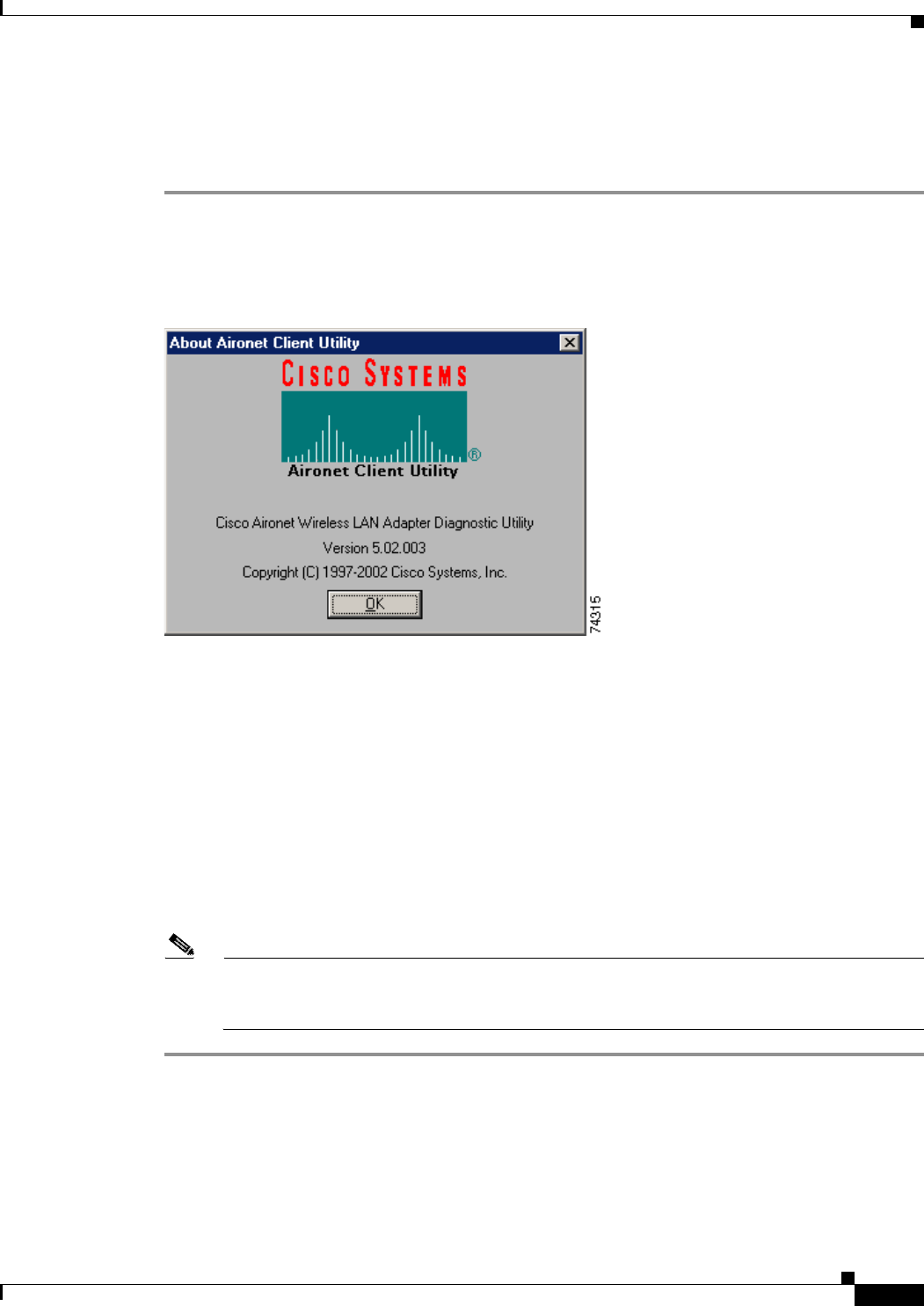
Step 1 To determine the version of ACU that your client adapter is currently using, open ACU; then click the
About icon or select the About Aironet Client Utility option from the Help drop-down menu. The
About Aironet Client Utility screen appears (see Figure 8-5).
Figure 8-5 About Aironet Client Utility Screen
Step 2 To determine the latest version of ACU available on Cisco.com, follow the steps below:
a. Use your computer’s web browser to access the following URL:
http://www.cisco.com/public/sw-center/sw-wireless.shtml
b. Locate the section for client adapter drivers and utilities.
c. Click the link for individual Windows files.
d. Locate the ACU files and find the one with the greatest release number. This is the latest available
version on Cisco.com.
Step 3 If the version of ACU available from Cisco.com has a higher number than the version currently being
used by your client adapter, follow the instructions in the “Upgrading ACU” section on page 8-22 to
upgrade ACU.
Note If a version of ACU prior to 4.13 is installed on your computer, you must uninstall it before
you can upgrade to a more recent version. Refer to the “Uninstalling ACU Versions Prior to
4.13” section on page 8-24 for instructions.

BETA DRAFT - CISCO CONFIDENTIAL
8-22
Cisco Aironet Wireless LAN Client Adapters Installation and Configuration Guide for Windows OL-1394-03
Chapter 8 Routine Procedures
ACU Procedures
Upgrading ACU
Follow the instructions in this section to upgrade ACU to a more recent version.
Note If you create profiles using ACU version 5.0 (or greater), these profiles are saved if you upgrade to
a more recent version of ACU.
Step 1 Close any Windows programs that are running.
Step 2 Use the computer’s web browser to access the following URL:
http://www.cisco.com/public/sw-center/sw-wireless.shtml
Step 3 Locate the section for client adapter drivers and utilities.
Step 4 Click the link for individual Windows files.
Step 5 Select the latest ACU file.
Step 6 Read and accept the terms and conditions of the Software License Agreement.
Step 7 Select the ACU file to download it.
Step 8 Save the file to your computer’s hard drive.
Step 9 Locate the file using Windows Explorer, double-click it, and extract its files to a folder.
Step 10 Select Start > Run, enter or browse to the path where you extracted the files (for example,
C:\temp\setup.exe), and click OK. The Aironet Client Utility Setup screen and the InstallShield Wizard
appear.
Step 11 When the Welcome screen appears, click Next.
Step 12 In the Select Options screen, select as many of the following options as desired and click Next:
Option Description
LEAP Enables you to create a profile in ACU that uses LEAP authentication.
If this option is not selected now and you later want to use LEAP, you
must run this installation program again, select Modify, and select this
option.
Note Refer to Chapter 5 for information on using LEAP.
Note If you select LEAP on a Windows 95, 98, or 98 SE device,
Microsoft hot fixes are installed during ACU installation to fix
two problems related to the use of LEAP. Refer to Chapter 9 for
more information on the hot fixes.
Note If you select LEAP on a Windows XP device, you cannot use
Windows XP’s fast user switching feature.
Allow Saved LEAP User
Name and Password Enables you to create a profile in ACU that uses a saved (rather than
temporary) username and password for LEAP authentication. When
such a profile is used, the saved username and password are used to
start the LEAP authentication process, and you are not prompted to
enter them.
Note This option is available only if the LEAP option is selected.

BETA DRAFT - CISCO CONFIDENTIAL
8-23
Cisco Aironet Wireless LAN Client Adapters Installation and Configuration Guide for Windows
OL-1394-03
Chapter 8 Routine Procedures ACU Procedures
Step 13 In the Choose Destination Location screen, perform one of the following:
•If you want the ACU program files to be installed in the default location (C:\Program Files, if
C:\Program Files is the default Windows program file folder), click Next.
•If you want to specify a different destination location for the ACU program files, click Browse,
select a location, and click Next.
Step 14 In the Select Program Folder screen, specify a program folder name for ACU by selecting from the list
of existing folders (the default name is Cisco Aironet) or typing in a new folder name; then click Next.
A status screen displays the progress of the installation. Then one of two Setup Complete screens
displays, depending on whether Windows needs to be restarted to complete the installation.
Step 15 Perform one of the following:
•If your computer does not need to be rebooted, select either of the following options and click
Finish:
•If your computer needs to be rebooted, select Yes, I want to restart my computer now or No, I will
restart my computer later and click Finish.
Note If you are prompted to reboot your computer, Cisco recommends that you select the Ye s,
I want to restart my computer now option.
The ACU upgrade is complete.
Create ACU Icon on your
Desktop Causes the installation program to add an ACU icon to your computer’s
desktop to provide quick access to the utility.
Allow Non-Administrator
Users to use ACU to modify
profiles
Enables users without administrative rights to modify profiles in ACU
on computers running Windows NT, 2000, or XP.
Note This option is not available for Windows 95, 98, and Me
because these versions of Windows do not support different
classes of users.
Option Description
View the README.TXT file Opens a read-me file containing information about ACU.
Launch the Aironet Client
Utility Opens ACU so you can configure your client adapter.

BETA DRAFT - CISCO CONFIDENTIAL
8-24
Cisco Aironet Wireless LAN Client Adapters Installation and Configuration Guide for Windows OL-1394-03
Chapter 8 Routine Procedures
ACU Procedures
Uninstalling ACU
The procedure for uninstalling ACU varies based on the software’s version number. Follow the
instructions in one of the sections below to uninstall ACU.
Uninstalling ACU Versions Prior to 4.13
If a version of ACU earlier than 4.13 is installed on your computer, Cisco recommends that you uninstall
it before installing ACU version 5.0 or greater. Follow the steps below to uninstall a version of ACU
prior to 4.13.
Step 1 Double-click My Computer, Control Panel, and Add/Remove Programs.
Step 2 Select the Aironet Client Utility (ACU).
Step 3 Click Add/Remove or Change/Remove.
Step 4 When prompted to confirm your decision, click Yes. ACU is uninstalled.
Uninstalling ACU Version 4.13 or Greater
Follow the steps below if you ever need to uninstall ACU version 4.13 or greater and its setup program.
Note Cisco does not recommend uninstalling ACU version 4.13 or greater before installing the latest
version of ACU.
Step 1 Close any Windows programs that are running.
Step 2 Select Start > Run, enter the path to the installed ACU files (the default location is C:\Program
Files\Cisco Aironet\setup.exe), and click OK. The Welcome screen for the Aironet Client Utility setup
maintenance program appears.
Step 3 Select Remove and click Next.
Step 4 When asked if you want to completely remove the selected application and all of its components, click
OK. The Setup Complete screen appears.
Step 5 If your computer needs to be rebooted, select Yes, I want to restart my computer now or No, I will
restart my computer later.
Note If you are prompted to reboot your computer, Cisco recommends that you select the Yes, I
want to restart my computer now option. If you choose to restart your computer later, a
warning appears indicating that the installed software might not work properly if you do not
restart Windows, especially before installing ACU again.
Step 6 Click Finish. ACU is uninstalled.

BETA DRAFT - CISCO CONFIDENTIAL
8-25
Cisco Aironet Wireless LAN Client Adapters Installation and Configuration Guide for Windows
OL-1394-03
Chapter 8 Routine Procedures Restarting the Client Adapter
Deleting the ACU Icon from the Desktop
An ACU icon is automatically added to the desktop when you install ACU, provided you selected this
option during installation. If you wish to remove this icon from your desktop, right-click the icon, click
Delete, and click Yes to confirm your decision.
Restarting the Client Adapter
ACU enables you to re-initialize (or restart) the client adapter without having to reboot your computer
or eject and reinsert the adapter. For instance, if your client adapter is experiencing poor throughput, you
might want to restart the client adapter to try to force it to disassociate from the access point to which it
is currently associated in the hope that it will reassociate to an access point with a stronger signal.
Note Restarting the client adapter may cause you to lose your wireless network connection.
Follow the steps below to restart the client adapter.
Step 1 Open ACU.
Step 2 Select the Restart Card option from the Commands drop-down menu (see Figure 8-4).
Step 3 When prompted to confirm your decision, click Yes. The driver stops the client adapter’s radio, writes
the configuration (although no parameter settings have been changed), and restarts the radio. The status
bar at the bottom of the ACU screen shows the client adapter losing association and then reassociating.
Turning Your Client Adapter’s Radio On or Off
Your client adapter’s radio can be turned on or off. Turning the radio off prevents the adapter from
transmitting RF energy. You might want to turn off the client adapter’s radio when you are not
transmitting data and want to conserve battery power or when you are using a laptop on an airplane and
want to prevent the adapter’s transmissions from potentially interfering with the operation of certain
devices.
When the radio is on, it periodically sends out beacons even if it is not associated to an access point, as
required by the 802.11 specification. Therefore, it is important to turn it off around devices that are
susceptible to RF interference.
Note Your client adapter is not associated while the radio is off.
Follow the instructions below to turn the client adapter’s radio on or off.
•If your client adapter’s radio is on, opening ACU and selecting Radio Off from the Commands
drop-down menu (see Figure 8-4) turns the radio off. The status bar at the bottom of the ACU screen
indicates that the radio is turned off.
•If your client adapter’s radio is off, opening ACU and selecting Radio On from the Commands
drop-down menu (see Figure 8-4) turns the radio on.

BETA DRAFT - CISCO CONFIDENTIAL
8-26
Cisco Aironet Wireless LAN Client Adapters Installation and Configuration Guide for Windows OL-1394-03
Chapter 8 Routine Procedures
Uninstalling Microsoft Hot Fixes
Uninstalling Microsoft Hot Fixes
When LEAP is selected during ACU installation on a Windows 95, 98, or 98 SE device, Microsoft hot
fixes are also installed to fix two problems related to the use of LEAP. If you ever need to uninstall the
hot fixes, select Start > Run, enter C:\Windows\Inf\Qfe\W98.se\241052un.inf, and click OK.

CHAPTER
9-1
Cisco Aironet Wireless LAN Client Adapters Installation and Configuration Guide for Windows
OL-1394-03
9
Troubleshooting
This chapter provides information for diagnosing and correcting common problems encountered when
installing or operating the client adapter.
The following topics are covered in this chapter:
•Accessing the Latest Troubleshooting Information, page 9-2
•Interpreting the Indicator LEDs, page 9-2
•Troubleshooting the Client Adapter, page 9-3
•Error Messages, page 9-9
•Getting Help, page 9-15

BETA DRAFT - CISCO CONFIDENTIAL
9-2
Cisco Aironet Wireless LAN Client Adapters Installation and Configuration Guide for Windows OL-1394-03
Chapter9 Troubleshooting
Accessing the Latest Troubleshooting Information
Accessing the Latest Troubleshooting Information
This chapter provides basic troubleshooting tips for your client adapter. For more up-to-date and
complex troubleshooting information, refer to the TAC web site at
http://www.cisco.com/public/support/tac/home.shtml. Select Wireless Technologies under Top Issues.
Interpreting the Indicator LEDs
Note Mini PCI cards do not have LEDs.
The client adapter shows messages and error conditions through its two LEDs:
•Link Integrity/Power LED (green) – This LED lights when the client adapter is receiving power
and blinks slowly when the adapter is linked with the network.
•Link Activity LED (amber) – This LED blinks quickly when the client adapter is receiving or
transmitting data and blinks in a repeating pattern to indicate an error condition.
Table 9-1 interprets the LED messages during normal operation. Table 9-2 interprets the LED error
condition messages.
Table 9-1 LED Normal Operating Messages
Green LED Amber LED Condition
Blinking quickly Blinking quickly Power is on, self-test is OK, and client adapter is
scanning for a network.
Blinking slowly Blinking quickly Client adapter is associated to an access point.
Continuously on or
blinking slowly Blinking Client adapter is transmitting or receiving data
while associated to an access point.
Off Blinking quickly Client adapter is in power save mode.
On continuously Blinking quickly Client adapter is in ad hoc mode.
Table 9-2 LED Error Condition Messages
Green LED Amber LED Condition
Off Off Client adapter is not receiving power or an error has
occurred.
Off 1 blink at 2-second rate RAM failure. Refer to the “Obtaining Technical
Assistance” section in the Preface for technical
support information.
Off 2-second pause, 2 fast
blinks, 1-second pause,
1 blink
A configuration error has occurred (for example,
WEP is enabled in ACU but the client adapter has
not been programmed with a valid WEP key).
Recheck your client adapter’s configuration settings
in ACU.

BETA DRAFT - CISCO CONFIDENTIAL
9-3
Cisco Aironet Wireless LAN Client Adapters Installation and Configuration Guide for Windows
OL-1394-03
Chapter 9 Troubleshooting Troubleshooting the Client Adapter
Troubleshooting the Client Adapter
This section provides troubleshooting tips if you encounter problems with your client adapter.
Problems Installing the Driver
If you experience problems during driver installation, you may want to restart the installation process.
Go to the “Uninstalling the Driver” section on page 8-13 to start with a clean install.
Problems Installing ACU
If your attempt to install ACU failed, follow the steps below to repair the installation.
Step 1 Close any Windows programs that are running.
Step 2 Select Start > Run, enter the path to the installed ACU files (the default location is C:\Program
Files\Cisco Aironet\setup.exe), and click OK. The Welcome screen for the Aironet Client Utility setup
maintenance program appears.
Step 3 Select Repair and click Next. The Setup Complete screen appears.
Off 2 fast blinks, 2-second
pause Flash boot block checksum failure. Refer to the
“Obtaining Technical Assistance” section in the
Preface for technical support information.
Off 3 fast blinks, 2-second
pause Firmware checksum failure. Reload the firmware.
Off 4 fast blinks, 2-second
pause MAC address error (error reading MAC chip).
Reload the firmware.
Off 5 fast blinks, 2-second
pause Physical layer (PHY) access error. Refer to the
“Obtaining Technical Assistance” section in the
Preface for technical support information.
Off 6 fast blinks, 2-second
pause Incompatible firmware. Load the correct firmware
version.
Table 9-2 LED Error Condition Messages (continued)
Green LED Amber LED Condition

BETA DRAFT - CISCO CONFIDENTIAL
9-4
Cisco Aironet Wireless LAN Client Adapters Installation and Configuration Guide for Windows OL-1394-03
Chapter9 Troubleshooting
Troubleshooting the Client Adapter
Step 4 If your computer needs to be rebooted, select Yes, I want to restart my computer now or No, I will
restart my computer later.
Note If you are prompted to reboot your computer, Cisco recommends that you select the Yes, I
want to restart my computer now option.
Step 5 Click Finish. The repair is complete. All of the selections you made during the previous installation are
maintained.
Client Adapter Recognition Problems
Note This section does not apply to mini PCI cards.
If your client adapter is not being recognized by your computer’s PCMCIA adapter, check your
computer’s BIOS and make sure that the PC card controller mode is set to PCIC compatible.
Note A computer’s BIOS varies depending on the manufacturer. For support on BIOS-related
issues, consult your computer’s manufacturer.
Resolving Resource Conflicts
Note This section does not apply to the mini PCI cards.
If you encounter problems while installing your client adapter on a computer running a Windows
operating system, you may need to specify a different interrupt request (IRQ) or I/O range for the
adapter.
The default IRQ for the client adapter is IRQ 10, which may not work for all systems. Follow the steps
for your specific operating system to obtain an available IRQ.
During installation the adapter’s driver installation script scans for an unused I/O range. The installation
can fail if the I/O range found by the driver installation script is occupied by another device but not
reported by Windows. An I/O range might not be reported if a device is physically present in the system
but not enabled under Windows. Follow the steps for your specific operating system to obtain an
available I/O range.

BETA DRAFT - CISCO CONFIDENTIAL
9-5
Cisco Aironet Wireless LAN Client Adapters Installation and Configuration Guide for Windows
OL-1394-03
Chapter 9 Troubleshooting Troubleshooting the Client Adapter
Resolving Resource Conflicts in Windows 95, 98, and Me
Step 1 Double-click My Computer, Control Panel, and System.
Step 2 Click the Device Manager tab.
Step 3 Double-click Network Adapters.
Step 4 Select the Cisco Systems wireless LAN adapter.
Step 5 Click the Properties button.
Step 6 In the General screen, the Device Status field indicates if a resource problem exists. If a problem is
indicated, click the Resources tab.
Step 7 Deselect the Use automatic settings checkbox.
Step 8 Under Resource Settings or Resource Type, click Input/Output Range.
Step 9 Look in the Conflicting Device list at the bottom of the screen. If it indicates that the range is being used
by another device, click the Change Setting button.
Step 10 Scroll through the ranges in the Value dialog box and select one that does not conflict with another
device. The Conflict Information window at the bottom of the screen indicates if the range is already
being used.
Step 11 Click OK.
Step 12 Under Resource Settings or Resource Type, click Interrupt Request.
Step 13 Look in the Conflicting Device list at the bottom of the screen. If it indicates that the IRQ is being used
by another device, click the Change Setting button.
Step 14 Scroll through the IRQs in the Value dialog box and select one that does not conflict with another device.
The Conflict Information window at the bottom of the screen indicates if the IRQ is already being used.
Step 15 Click OK.
Step 16 Reboot your computer.
Resolving Resource Conflicts in Windows NT
Step 1 Select Start > Programs > Administrative Tools > Windows NT Diagnostics.
Step 2 Click the Resources tab.
Step 3 Click the IRQ button.
Step 4 The used IRQs are listed in numerical order along the left side of the Resources window. Write down the
number of an IRQ that is not being used; you will need it for Step 11.
Step 5 Click the I/O Port button.
Step 6 The used I/O ranges are listed in numerical order along the left side of the Resources window under
Address. Write down an I/O range that is not being used (for example, if range 0100-013F is followed
by 0170-0177 in the list, then 0140-0169 is an available range); you will need it for Step 13.
Step 7 Double-click My Computer, Control Panel, and Network.
Step 8 Click the Adapters tab and select the Cisco Aironet wireless LAN adapter.
Step 9 Click Properties.

BETA DRAFT - CISCO CONFIDENTIAL
9-6
Cisco Aironet Wireless LAN Client Adapters Installation and Configuration Guide for Windows OL-1394-03
Chapter9 Troubleshooting
Troubleshooting the Client Adapter
Step 10 Select Interrupt under Property.
Step 11 Select the number of the unused interrupt from Step 4 in the Value drop-down box.
Step 12 Select IO Base Address under Property.
Step 13 Select a value that is within the unused range you determined in Step 6. For example, if your unused
range is 0140-0169, you could select 150.
Step 14 Click OK.
Resolving Resource Conflicts in Windows 2000
Step 1 Double-click My Computer, Control Panel, and System.
Step 2 Click the Hardware tab and Device Manager.
Step 3 Double-click Network Adapters and the Cisco Systems wireless LAN adapter.
Step 4 In the General screen, the Device Status field indicates if a resource problem exists. If a problem is
indicated, click the Resources tab.
Step 5 Deselect the Use automatic settings checkbox.
Step 6 Under Resource Settings or Resource Type, click Input/Output Range.
Step 7 Look in the Conflicting Device list at the bottom of the screen. If it indicates that the range is being used
by another device, click the Change Setting button.
Step 8 Scroll through the ranges in the Value dialog box and select one that does not conflict with another
device. The Conflict Information window at the bottom of the screen indicates if the range is already
being used.
Step 9 Click OK.
Step 10 Under Resource Settings or Resource Type, click Interrupt Request.
Step 11 Look in the Conflicting Device list at the bottom of the screen. If it indicates that the IRQ is being used
by another device, click the Change Setting button.
Step 12 Scroll through the IRQs in the Value dialog box and select one that does not conflict with another device.
The Conflict Information window at the bottom of the screen indicates if the IRQ is already being used.
Step 13 Click OK.
Step 14 Reboot your computer.

BETA DRAFT - CISCO CONFIDENTIAL
9-7
Cisco Aironet Wireless LAN Client Adapters Installation and Configuration Guide for Windows
OL-1394-03
Chapter 9 Troubleshooting Troubleshooting the Client Adapter
Resolving Resource Conflicts in Windows XP
Note These instructions assume you are using Windows XP’s classic view, not its category view.
Step 1 Double-click My Computer, Control Panel, and System.
Step 2 Click the Hardware tab and Device Manager.
Step 3 Under Network Adapters, double-click Cisco Systems 3x0 Series Wireless LAN Adapter.
Step 4 In the General screen, the Device Status field indicates if a resource problem exists. If a problem is
indicated, click the Resources tab.
Step 5 Deselect the Use automatic settings checkbox.
Step 6 Under Resource Settings, click I/O Range.
Step 7 Look in the Conflicting Device list at the bottom of the screen. If it indicates that the range is being used
by another device, click the Change Setting button.
Step 8 Scroll through the ranges in the Value dialog box and select one that does not conflict with another
device. The Conflict Information window at the bottom of the screen indicates if the range is already
being used.
Step 9 Click OK.
Step 10 Under Resource Settings, click IRQ.
Step 11 Look in the Conflicting Device list at the bottom of the screen. If it indicates that the IRQ is being used
by another device, click the Change Setting button.
Step 12 Scroll through the IRQs in the Value dialog box and select one that does not conflict with another device.
The Conflict Information window at the bottom of the screen indicates if the IRQ is already being used.
Step 13 Click OK.
Step 14 Reboot your computer.
Problems Associating to an Access Point
Follow the instructions below if your client adapter fails to associate to an access point.
•If possible, move your workstation a few feet closer to an access point and try again.
•Make sure the client adapter is securely inserted in your computer’s client adapter slot.
•If you are using a PCI client adapter, make sure the antenna is securely attached.
•Make sure the access point is turned on and operating.
•Check that all parameters are set properly for both the client adapter and the access point. These
include the SSID, EAP authentication, WEP activation, network type, channel, etc.

BETA DRAFT - CISCO CONFIDENTIAL
9-8
Cisco Aironet Wireless LAN Client Adapters Installation and Configuration Guide for Windows OL-1394-03
Chapter9 Troubleshooting
Troubleshooting the Client Adapter
•Follow the instructions in the previous section to resolve any resource conflicts. If you are using
Windows NT, you may also want to try disabling the Ethernet port.
•If the client adapter still fails to establish contact, refer to the “Obtaining Technical Assistance”
section in the Preface for technical support information.
Problems Authenticating to an Access Point
If your client adapter is a 40-bit card and LEAP or EAP is enabled, the adapter can associate to but not
authenticate to access points using 128-bit encryption. To authenticate to an access point using 128-bit
encryption, you have two options:
•Purchase a 128-bit client adapter. This is the most secure option.
•Disable static WEP for the client adapter and configure the adapter and the access point to associate
to mixed cells. This option presents a security risk because your data is not encrypted as it is sent
over the RF network.
Problems Connecting to the Network
After you have installed the appropriate driver and client utilities, contact your IS department if you have
a problem connecting to the network. Proxy server, network protocols, and further authentication
information might be needed to connect to the network.
Losing Association Upon Resuming from Suspend Mode
(Windows NT and Mini PCI Card Only)
Because Windows NT does not support resuming of mini PCI cards, your client adapter loses its
association to an access point upon resuming from suspend mode. If this occurs, restart your client
adapter to reassociate.
Parameters Missing from ACU Properties Screens
If some parameters are grayed out on the ACU Properties screens, your system administrator may have
used an auto installer to deactivate these parameters. In this case, these parameters are not available for
you to set.

BETA DRAFT - CISCO CONFIDENTIAL
9-9
Cisco Aironet Wireless LAN Client Adapters Installation and Configuration Guide for Windows
OL-1394-03
Chapter 9 Troubleshooting Error Messages
LEAP Login Screen Appears Before Windows Login Screen
If you are using Windows 95, 98, or Me and your client adapter is configured to use LEAP authentication
with an automatically prompted login, the LEAP login screen should appear before the Windows screen
after you reboot. If the Windows screen appears first, follow the steps below.
Step 1 On the Windows desktop, right-click the My Network Places icon.
Step 2 Click Properties.
Step 3 On the Network - Configuration screen, click the arrow on the right side of the Primary Network Logon
box.
Step 4 Select Cisco Aironet Wireless Logon and click OK.
Step 5 When prompted to restart your computer, click Yes.
Microsoft Hot Fixes
When LEAP is selected during ACU installation on a Windows 95, 98, or 98 SE device, Microsoft hot
fixes are also installed to fix two problems related to the use of LEAP. You can obtain descriptions of
these hot fixes and the problems they resolve at the following Microsoft URLs:
•http://support.microsoft.com/support/kb/articles/Q247/8/05.asp (for Windows 95, 98, and 98 SE)
•http://support.microsoft.com/support/kb/articles/Q165/4/02.asp (for Windows 95 only)
Note Only the English version of the hot fixes are installed. Foreign language versions of these operating
systems require hot fixes specific to those languages. Contact Microsoft Product Support Services to
obtain the hot fixes for languages other than English. Without the hot fixes installed, you may be
prompted to enter your credentials at the Windows login prompt twice. To work around this problem,
enter your login credentials again.
Error Messages
This section provides a list of error messages that may appear during the installation, configuration, or
use of your client adapter. The error messages are listed in alphabetical order, and an explanation as well
as a recommended user action are provided for each message.
Error Message Bad Firmware Image File (filename)
Explanation The selected firmware file is corrupt and will not be sent to the client adapter.
Recommended Action Select a different firmware file and try to load it.

BETA DRAFT - CISCO CONFIDENTIAL
9-10
Cisco Aironet Wireless LAN Client Adapters Installation and Configuration Guide for Windows OL-1394-03
Chapter9 Troubleshooting
Error Messages
Error Message Cannot find a wireless adapter that supports LEAP. Please make sure
that you have installed the correct client adapter and updated your firmware.
Explanation LEAP authentication failed because the client adapter’s firmware does not support
LEAP.
Recommended Action Follow the instructions in the “Upgrading the Firmware” section on page 8-5 to
install the latest client adapter firmware.
Error Message Cannot find a wireless adapter that supports WEP. Please make sure that
you have installed the correct client adapter and purchased WEP support.
Explanation LEAP authentication failed because the client adapter does not support WEP.
Recommended Action Make sure that you have installed the correct client adapter or upgrade the
adapter for WEP support.
Error Message Card Removed at xx:xx
Explanation The client adapter was ejected from the computer.
Recommended Action Reinsert the client adapter if you wish to resume wireless communications.
Error Message The combination of domain name and user name exceeds maximum number of
characters (32) that LEAP supports. Please uncheck Include Windows Logon Domain
with User Name in ACU or log on to a local computer, or use shorter names.
Explanation The combination of characters entered for the username and domain name in the
Windows login screen or the LEAP login screen exceed the maximum number supported by LEAP,
which is 32.
Recommended Action Perform one of the following:
–
Deselect the Include Windows Logon Domain With User Name checkbox in the LEAP
Settings screen of ACU.
–
Log on to a local computer, which does not use a domain name, and try to authenticate again.
–
Enter a set of credentials (username, password, and domain name) with fewer characters.
Error Message The current active profile is not configured for LEAP.
Explanation The Manual LEAP Login option was selected in ACU, but the active profile is not
configured for LEAP. The LEAP authentication process aborts.
Recommended Action If you want the client adapter to LEAP authenticate, select a profile that is
configured for LEAP.

BETA DRAFT - CISCO CONFIDENTIAL
9-11
Cisco Aironet Wireless LAN Client Adapters Installation and Configuration Guide for Windows
OL-1394-03
Chapter 9 Troubleshooting Error Messages
Error Message Error Reading filename
Explanation A problem occurred while the computer was reading the firmware file from the disk.
Recommended Action Re-copy the firmware file to a floppy disk or to your computer’s hard drive and
try to load it again or select a different firmware file and try to load it.
Error Message Error Writing to Flash Memory
Explanation A problem occurred while the firmware was being flashed.
Recommended Action Eject the client adapter and reinsert it. If the client adapter functions properly,
the firmware was flashed successfully. If the client adapter does not function or functions improperly,
your client adapter may need to be returned for service. Refer to the “Technical Assistance Center”
section in the Preface for information on contacting TAC.
Error Message Firmware Incompatible with Hardware
Explanation The selected firmware file does not work with the client adapter.
Recommended Action Select a different firmware file and try to load it.
Error Message Firmware Upgrade Failed
Explanation A problem occurred while the firmware was being flashed.
Recommended Action Eject the client adapter and reinsert it. If the client adapter functions properly,
the firmware was flashed successfully. If the client adapter does not function or functions improperly,
your client adapter may need to be returned for service. Refer to the “Technical Assistance Center”
section in the Preface for information on contacting TAC.
Error Message Maximum Power Save Mode Will Be Temporarily Disabled While You Are
Running This Application!
Explanation The client adapter cannot be run in Max PSP mode while ACU is running.
Recommended Action No user action is required. The client adapter automatically runs in Fast PSP
mode while ACU is running.
Error Message No Wireless LAN Adapters Found
Explanation A client adapter is not inserted in the computer.
Recommended Action Insert a client adapter if you wish to start wireless communications.

BETA DRAFT - CISCO CONFIDENTIAL
9-12
Cisco Aironet Wireless LAN Client Adapters Installation and Configuration Guide for Windows OL-1394-03
Chapter9 Troubleshooting
Error Messages
Error Message No Wireless LAN Adapters Installed!
Explanation An attempt was made to start ACU without a client adapter being inserted in the
computer. ACU cannot execute if a client adapter is not inserted because it needs to be able to read
from and write to the adapter.
Recommended Action Insert a client adapter and start ACU.
Error Message The profile will be disabled until Windows restarts or the card is
ejected and reinserted. Are you sure?
Explanation The username and password for your current profile have expired or are no longer valid.
When the LEAP login screen appeared, prompting you to enter your new username and password,
you selected Cancel.
Recommended Action Click No, enter your new username and password when the LEAP login screen
reappears, and click OK. The client adapter should authenticate using your new credentials. If the
profile uses saved credentials, edit the profile in ACU by changing the username and password on the
LEAP Settings screen and save your changes. (If you select Yes, the profile will be disabled until you
reboot your system or eject and reinsert the card.)
Error Message A recently installed program has disabled the Welcome screen and Fast
User Switching. To restore these features, you must uninstall the program. The
following file name might help you identify the program that made the change:
cswGina.dll. (Windows XP only)
Explanation LEAP was selected during ACU installation on a Windows XP computer; then the
Change the way users log on or off option was selected under Windows XP’s User Accounts.
Recommended Action If LEAP is selected during ACU installation, you cannot use Windows XP’s fast
user switching feature. If you want to use fast user switching and do not want to use LEAP, you must
run the ACU installation program again, select Modify, and deselect LEAP.
Error Message Software installed might not work properly if you choose not to restart
Windows. Please make sure to restart Windows before installing Aironet Client
Utility again.
Explanation The No, I will restart my computer later option was selected on the Setup Complete
screen during an uninstall of ACU.
Recommended Action Restart your computer before installing ACU again.

BETA DRAFT - CISCO CONFIDENTIAL
9-13
Cisco Aironet Wireless LAN Client Adapters Installation and Configuration Guide for Windows
OL-1394-03
Chapter 9 Troubleshooting Error Messages
Error Message To run LEAP successfully, you will have to apply Microsoft Q241052
Update for the language version of your operating system as documented on
http://support.microsoft.com/support/kb/articles/Q247/8/05.asp. Please contact
Microsoft Product Support Services to obtain the fix.
Explanation When LEAP is selected during ACU installation on a Windows 95, 98, or 98 SE device,
Microsoft hot fixes are also installed to fix two problems related to the use of LEAP. However, only
the English version of the hot fixes are installed. Foreign language versions of these operating
systems require hot fixes specific to those languages.
Recommended Action Contact Microsoft Product Support Services to obtain the hot fixes for
languages other than English. Without the hot fixes installed, you may be prompted to enter your
credentials at the Windows login prompt twice. To work around this problem, enter your login
credentials again.
Error Message Unable to authenticate wireless user. Please make sure you have entered
the right user name and password and try again.
Explanation LEAP authentication failed.
Recommended Action Re-enter the LEAP user name and password or cancel the LEAP authentication.
To start another LEAP authentication process, log off and log in again or select Manual LEAP Login
from the Commands drop-down menu.
Error Message Unable to Open filename
Explanation The selected firmware file cannot be found.
Recommended Action Re-copy the firmware file to a floppy disk or to your computer’s hard drive and
try to load it again or select a different firmware file and try to load it.
Error Message The user name and password entered for profile 'xxx' are no longer
valid and have failed the LEAP authentication. Please enter a new user name and
password.
Explanation The username and password for your current profile have expired or are no longer valid;
therefore, your client adapter is unable to LEAP authenticate.
Recommended Action When the LEAP login screen appears, enter your new username and password
and click OK. The client adapter should authenticate using your new credentials.

BETA DRAFT - CISCO CONFIDENTIAL
9-14
Cisco Aironet Wireless LAN Client Adapters Installation and Configuration Guide for Windows OL-1394-03
Chapter9 Troubleshooting
Error Messages
Error Message The user name and password entered for saved profile 'xxx' are no
longer valid and have failed the LEAP authentication. Please enter a new user name
and password. Please also remember to change them permanently in the saved profile
using the ACU Profile Manager.
Explanation The username and password for your current profile, which uses saved credentials, have
expired or are no longer valid; therefore, your client adapter is unable to LEAP authenticate.
Recommended Action When the LEAP login screen appears, enter your new username and password
and click OK. The client adapter should authenticate using your new credentials. Then edit the
profile in ACU by changing the username and password on the LEAP Settings screen and save your
changes.
Error Message You cannot run a linktest because the radio in your Wireless LAN
Adapter is not on!
Explanation An attempt was made to run a link test while the client adapter’s radio was off.
Recommended Action Turn on the client adapter’s radio by selecting Radio On from the Commands
drop-down menu; then run the link test.
Error Message You cannot run a linktest because your Cisco Wireless LAN Adapter is
not associated!
Explanation An attempt was made to run a link test while the client adapter was not associated to an
access point or other wireless device.
Recommended Action Run the link test after the client adapter is associated to an access point or
another wireless device.
Error Message You must specify an IP address before running a linktest!
Explanation An attempt was made to run a link test although the IP address of the access point or other
wireless device with which to test the RF link was not specified.
Recommended Action In the Linktest screen’s IP Address of Access Point field, enter the IP address
of the access point or other wireless device with which you want to test the RF link.
Error Message You need to be an administrator or a user with administrative rights
to install Aironet Client Utility. Please log on as a different user and try again.
Explanation A non-administrative user attempted to install ACU. The ACU installation process
terminates.
Recommended Action Logon as a different user and attempt the installation process again.

BETA DRAFT - CISCO CONFIDENTIAL
9-15
Cisco Aironet Wireless LAN Client Adapters Installation and Configuration Guide for Windows
OL-1394-03
Chapter 9 Troubleshooting Getting Help
Error Message Wireless Connection Unavailable. (Windows XP only)
Explanation ACU was used to configure the client adapter on Windows XP, but the Use Windows to
configure my wireless network settings checkbox in Windows XP is selected. This message appears
even if the client adapter is associated to an access point.
Recommended Action Deselect the Use Windows to configure my wireless network settings
checkbox in Windows XP to force Windows to display the correct status.
Getting Help
To access information about ACU, open ACU; then click the Help icon or select Contents from the Help
drop-down menu. An overview of ACU is displayed.
From the Overview of the Aironet Client Utility screen, you can access additional information.
•To access information on specific menu options, click Contents; double-click Aironet Client
Utility Commands, the desired menu (such as Options Menu), and the desired topic (such as
Preferences).
•To access information on specific parameters, click Contents; double-click Configurable
Parameters, the client adapter, a parameter category (such as System Parameters), and the desired
parameter (such as SSID).
•To access information on specific diagnostic topics, click Contents; double-click Run Time
Diagnostic Information, a diagnostic category (such as Running a Linktest), and the desired topic
(such as Packet Size).
•To search for a specific topic, click Index, select an index entry, and click Display.
•To search for a specific word or phrase, click Contents or Index, click the Find tab, and follow the
instructions in the Find Setup Wizard window.

BETA DRAFT - CISCO CONFIDENTIAL
9-16
Cisco Aironet Wireless LAN Client Adapters Installation and Configuration Guide for Windows OL-1394-03
Chapter9 Troubleshooting
Getting Help

A-1
Cisco Aironet Wireless LAN Client Adapters Installation and Configuration Guide for Windows
OL-1394-03
APPENDIX
A
Technical Specifications
This appendix provides technical specifications for the Cisco Aironet 11-Mbps 2.4-GHz and 54-Mbps
5-GHz client adapters.
The following topics are covered in this appendix:
•Physical Specifications, page A-2
•Radio Specifications, page A-3
•Power Specifications, page A-6
•Safety and Regulatory Compliance Specifications, page A-7

BETA DRAFT - CISCO CONFIDENTIAL
A-2
Cisco Aironet Wireless LAN Client Adapters Installation and Configuration Guide for Windows OL-1394-03
Appendix A Technical Specifications
Table A-1 lists the technical specifications for the Cisco Aironet 11-Mbps 2.4-GHz and 54-Mbps 5-GHz
client adapters.
Note If a distinction is not made between radio or client adapter type, the specification applies to all Cisco
Aironet client adapters.
Table A-1 Technical Specifications for Cisco Aironet Client Adapters
Physical Specifications
Size
PC card and PC-Cardbus
card 4.5 in. L x 2.1 in. W x 0.2 in. H
(11.3 cm L x 5.4 cm W x 0.5 cm H)
LM card 3.4 in. L x 2.1 in. W x 0.2 in. H
(8.6 cm L x 5.4 cm W x 0.5 cm H)
PCI card 5.8 in. L x 3.2 in. W x 0.5 in. H
(14.7 cm L x 8.1 cm W x 1.3 cm H)
Mini PCI card 2.3 in. L x 2.0 in. W x 0.2 in. H
(6.0 cm L x 5.1 cm W x 0.5 cm H)
Weight
PC card and LM card 1.3 oz (0.037 kg)
PCI card 4.6 oz (0.13 kg)
Mini PCI card 0.5 oz (0.014 kg)
PC-Cardbus card 2.0 oz (0.06 kg)
Enclosure
PC card and PC-Cardbus
card Extended Type II PC card
LM card Standard Type II PC card with RF connectors
Connector
PC card and LM card 68-pin PCMCIA
PCI card PCI card edge
PC-Cardbus card 68-pin Cardbus
Status indicators Green and amber LEDs (except mini PCI card); see Chapter 9
Operating temperature
350 series client adapters –22oF to 158oF (–30oC to 70oC)
340 series client adapters 32oF to 158oF (0oC to 70oC)
5-GHz client adapters –22oF to 158oF (–30oC to 70oC)
Storage temperature –40oF to 185oF (–40oC to 85oC)
Humidity (non-operational) 95% relative humidity

BETA DRAFT - CISCO CONFIDENTIAL
A-3
Cisco Aironet Wireless LAN Client Adapters Installation and Configuration Guide for Windows
OL-1394-03
Appendix A Technical Specifications
Altitude Operational
9843 ft (3000 m) @ room temperature for
2 hours
Non-operational
15,000 ft (4572 m) @ room temperature for
20 hours
ESD 15 kV (human body model)
Radio Specifications
Type
2.4-GHz client adapters Direct-sequence spread spectrum (DSSS)
IEEE 802.11b compliant
5-GHz client adapters Orthogonal frequency division multiplexing (OFDM) IEEE 802.11a
compliant
Power output
Note Refer to Appendix D for limitations on radiated power (EIRP) levels in the European
community and other countries.
Note If you are using an older version of a 340 or 350 series client adapter, your power level options
may be different than those listed here.
350 series client adapters 100 mW (20 dBm)
50 mW (17 dBm)
30 mW (15 dBm)
20 mW (13 dBm)
5 mW (7 dBm)
1 mW (0 dBm)
340 series PC card 30 mW (15 dBm)
1 mW (0 dBm)
340 series LM card and
PCI card 30 mW (15 dBm)
15 mW (12 dBm)
5 mW (7 dBm)
1 mW (0 dBm)
PC-Cardbus card 20 mW (13 dBm)
10 mW (10 dBm)
5 mW (7 dBm)
Note These values are based on the FCC peak measurement
method as defined in FCC 15.407(a)(4).
Operating frequency
2.4-GHz client adapters 2.400 to 2.497 GHz (depending on the regulatory domain in which
the client adapter is used)
5-GHz client adapters 5.15 to 5.25 GHz in the UNII 1 band*
5.25 to 5.35 GHz in the UNII 2 band*
*Depending on the regulatory domain in which the client adapter is
used
Table A-1 Technical Specifications for Cisco Aironet Client Adapters (continued)

BETA DRAFT - CISCO CONFIDENTIAL
A-4
Cisco Aironet Wireless LAN Client Adapters Installation and Configuration Guide for Windows OL-1394-03
Appendix A Technical Specifications
Usable channels
2.4-GHz client adapters 2412 to 2484 MHz in 5-MHz increments
5-GHz client adapters 5180 to 5320 MHz in 20-MHz increments
Interference rejection
2.4-GHz client adapters –35 dBc adjacent channel rejection
5-GHz client adapters 16 dBc @ 6 Mbps
15 dBc @ 9 Mbps
13 dBc @ 12 Mbps
11 dBc @ 18 Mbps
8 dBc @ 24 Mbps
4 dBc @ 36 Mbps
0 dBc @ 48 Mbps
–1 dBc @ 54 Mbps
Data rates
2.4-GHz client adapters 1, 2, 5.5, and 11 Mbps
5-GHz client adapters 6, 9, 12, 18, 24, 36, 48, and 54 Mbps
Modulation Binary phase shift keying (BPSK) - 1 Mbps
Quaternary phase shift keying (QPSK) - 2 Mbps
Complementary code keying (CCK) - 5.5 and 11 Mbps
Orthogonal frequency division multiplexing (OFDM) - 6 to 54 Mbps
Receiver sensitivity
350 series client adapters –94 dBm @ 1 Mbps
–91 dBm @ 2 Mbps
–89 dBm @ 5.5 Mbps
–85 dBm @ 11 Mbps
340 series client adapters –90 dBm @ 1 Mbps
–88 dBm @ 2 Mbps
–87 dBm @ 5.5 Mbps
–83 dBm @ 11 Mbps
5-GHz client adapters –85 dBm @ 6 Mbps
–84 dBm @ 9 Mbps
–82 dBm @ 12 Mbps
–80 dBm @ 18 Mbps
–77 dBm @ 24 Mbps
–73 dBm @ 36 Mbps
–69 dBm @ 48 Mbps
–68 dBm @ 54 Mbps
Receiver delay spread (multipath)
2.4-GHz client adapters 500 ns @ 1 Mbps
400 ns @ 2 Mbps
300 ns @ 5.5 Mbps
140 ns @ 11 Mbps (350 series client adapters)
70 ns @ 11 Mbps (340 series client adapters)
5-GHz client adapters TBD
Table A-1 Technical Specifications for Cisco Aironet Client Adapters (continued)

BETA DRAFT - CISCO CONFIDENTIAL
A-5
Cisco Aironet Wireless LAN Client Adapters Installation and Configuration Guide for Windows
OL-1394-03
Appendix A Technical Specifications
Range
350 series client adapters Outdoor
2000 ft (609.6 m) @ 1 Mbps
1500 ft (457.2 m) @ 2 Mbps
1000 ft (304.8 m) @ 5.5 Mbps
800 ft (243.8 m) @ 11 Mbps
Indoor
350 ft (106.7 m) @ 1 Mbps
250 ft (76.2 m) @ 2 Mbps
200 ft (61 m) @ 5.5 Mbps
150 ft (45.7 m) @ 11 Mbps
Note The above range numbers assume the use of a snap-on
antenna with the LM card.
340 series client adapters Outdoor
1500 ft (457.2 m) @ 1 Mbps
1200 ft (365.8 m) @ 2 Mbps
800 ft (243.8 m) @ 5.5 Mbps
400 ft (121.9 m) @ 11 Mbps
Indoor
300 ft (91.4 m) @ 1 Mbps
225 ft (68.6 m) @ 2 Mbps
150 ft (45.7 m) @ 5.5 Mbps
100 ft (30.5 m) @ 11 Mbps
Note The above range numbers assume the use of a snap-on
antenna with the LM card.
5-GHz client adapters Indoor
TBD
Antenna
PC card Integrated diversity antenna
LM card Two MMCX antenna connectors
PCI card RP-TNC connector
Mini PCI card Ultra-miniature SMT U.FL antenna connectors
PC-Cardbus card Integrated aperture coupled patch antenna
Table A-1 Technical Specifications for Cisco Aironet Client Adapters (continued)

BETA DRAFT - CISCO CONFIDENTIAL
A-6
Cisco Aironet Wireless LAN Client Adapters Installation and Configuration Guide for Windows OL-1394-03
Appendix A Technical Specifications
Power Specifications
Operational voltage
PC, LM, and PCI card 5.0 V (+ or – 0.25 V)
Mini PCI card 3.0 to 3.6 V
PC-Cardbus card 3.3 V (+ or – 0.33 V)
Receive current steady state
PC card and LM card Typically 250 mA
PCI card Typically 350 mA
Mini PCI card Typically 330 mA
PC-Cardbus card TBD
Transmit current steady state
350 series PC card and LM
card Typically 450 mA @ 20 dBm
350 series PCI card Typically 550 mA @ 20 dBm
350 series mini PCI card Typically 570 mA @ 20 dBm
340 series PC card and LM
card Typically 350 mA @ 15 dBm
340 series PCI card Typically 450 mA @ 15 dBm
PC-Cardbus card TBD
Sleep mode steady state
350 series PC card, LM
card, and mini PCI card Typically 15 mA
350 series PCI card Typically 115 mA
340 series PC card and LM
card Typically 15 mA
340 series PCI card Typically 110 mA
PC-Cardbus card TBD
Table A-1 Technical Specifications for Cisco Aironet Client Adapters (continued)

BETA DRAFT - CISCO CONFIDENTIAL
A-7
Cisco Aironet Wireless LAN Client Adapters Installation and Configuration Guide for Windows
OL-1394-03
Appendix A Technical Specifications
Safety and Regulatory Compliance Specifications
Safety Designed to meet:
•UL 1950 Third Ed.
•CSA 22.2 No. 950-95
•IEC 60950 Second Ed., including Amendments 1-4 with all
deviations
•EN 60950 Second Ed., including Amendments 1-4
EMI and susceptibility FCC Part 15.107 & 15.109 Class B
ICES-003 Class B (Canada)
EN 55022 B
AS/NZS 3548 Class B
VCCI Class B
EN 55024
EN 301.489-1 and EN-301.489-17
Radio approvals FCC Part 15.247
Canada RSS-139-1 (2.4-GHz client adapters), RSS-210
Japan Telec 33B (2.4-GHz client adapters)
Japan ARIB STD-T71 (5-GHz client adapters)
EN 300.328 (2.4-GHz client adapters)
EN 301.893 (5-GHz client adapters)
RF exposure OET-65C
RSS-102
ANSI C95.1
Table A-1 Technical Specifications for Cisco Aironet Client Adapters (continued)

BETA DRAFT - CISCO CONFIDENTIAL
A-8
Cisco Aironet Wireless LAN Client Adapters Installation and Configuration Guide for Windows OL-1394-03
Appendix A Technical Specifications

B-1
Cisco Aironet Wireless LAN Client Adapters Installation and Configuration Guide for Windows
OL-1394-03
APPENDIX
B
Translated Safety Warnings
This appendix provides translations of the safety warnings that appear in this publication.
The following topics are covered in this appendix:
•Explosive Device Proximity Warning, page B-2
•Dipole Antenna Installation Warning, page B-3
•Warning for Laptop Users, page B-4

BETA DRAFT - CISCO CONFIDENTIAL
B-2
Cisco Aironet Wireless LAN Client Adapters Installation and Configuration Guide for Windows OL-1394-03
Appendix B Translated Safety Warnings
Explosive Device Proximity Warning
Explosive Device Proximity Warning
Warning
Do not operate your wireless network device near unshielded blasting caps or in an explosive
environment unless the device has been modified to be especially qualified for such use.
Waarschuwing
Gebruik dit draadloos netwerkapparaat alleen in de buurt van onbeschermde ontstekers of in
een omgeving met explosieven indien het apparaat speciaal is aangepast om aan de eisen voor
een dergelijk gebruik te voldoen.
Varoitus
Älä käytä johdotonta verkkolaitetta suojaamattomien räjäytysnallien läheisyydessä tai
räjäytysalueella, jos laitetta ei ole erityisesti muunnettu sopivaksi sellaiseen käyttöön.oen.
Attention
Ne jamais utiliser un équipement de réseau sans fil à proximité d'un détonateur non blindé ou
dans un lieu présentant des risques d'explosion, sauf si l'équipement a été modifié à cet effet.
Warnung
Benutzen Sie Ihr drahtloses Netzwerkgerät nicht in der Nähe ungeschützter Sprengkapseln oder
anderer explosiver Stoffe, es sei denn, Ihr Gerät wurde eigens für diesen Gebrauch modifiziert
und bestimmt.
Avvertenza
Non utilizzare la periferica di rete senza fili in prossimità di un detonatore non protetto o di
esplosivi a meno che la periferica non sia stata modificata a tale proposito.
Advarsel
Ikke bruk den trådløse nettverksenheten nært inntil uisolerte fenghetter eller i et eksplosivt
miljø med mindre enheten er modifisert slik at den tåler slik bruk.
Aviso
Não opere o dispositivo de rede sem fios perto de cápsulas explosivas não protegidas ou num
ambiente explosivo, a não ser que o dispositivo tenha sido modificado para se qualificar
especialmente para essa utilização.
¡Advertencia!
No utilizar un aparato de la red sin cable cerca de un detonador que no esté protegido ni
tampoco en un entorno explosivo a menos que el aparato haya sido modificado con ese fin.
Varning!
Använd inte den trådlösa nätverksenheten i närheten av oskyddade tändhattar eller i en
explosiv miljö om inte enheten modifierats för att kunna användas i sådana sammanhang.

BETA DRAFT - CISCO CONFIDENTIAL
B-3
Cisco Aironet Wireless LAN Client Adapters Installation and Configuration Guide for Windows
OL-1394-03
Appendix B Translated Safety Warnings Dipole Antenna Installation Warning
Dipole Antenna Installation Warning
Warning
In order to comply with FCC radio frequency (RF) exposure limits, dipole antennas should be
located at a minimum of 7.9 inches (20 cm) or more from the body of all persons.
Waarschuwing
Om te voldoen aan de FCC radiofrequentie (RF) blootstellingslimieten dienen dipoolantennes
zich minstens 20 cm of meer van de lichamen van alle personen bevinden.
Varoitus
FCC:n antamien radiotaajuuksille altistumista koskevien rajoitusten mukaan dipoliantennien on
sijaittava vähintään 20 cm:n päässä kaikista henkilöistä.
Attention
Pour se conformer aux limites d’exposition à la fréquence radio préconisées par la FCC (Federal
Communications Commission), les antennes dipôles doivent se situer à un minimum de 20 cm de
toute personne.
Warnung
Um die in den FCC-Richtlinien festgelegten Expositionshöchstgrenzen für Radiofrequenzen (RF)
nicht zu überschreiten, sollten Dipolantennen mindestens 20 cm (7,9 Zoll) vom Körper aller
Person entfernt aufgestellt werden.
Avvertenza
Per conformarsi ai limiti FCC di esposizione a radiofrequenza (RF), le antenne a dipolo devono
stare ad una distanza minima di 20 cm dal corpo di ogni persona.
Advarsel
I henhold til eksponeringsgrensene for radiofrekvenser (RF), skal dipole antenner befinne seg
på en avstand av minst 20 cm eller mer fra mennesker.
Aviso
Para estar de acordo com as normas FCC de limites de exposição para freqüência de rádio (RF),
as antenas dipolo devem estar distantes no mínimo 20 cm (7,9 pol) do corpo de qualquer pessoa.
¡Advertencia!
Para cumplir con los límites de exposición de radio frecuencia (RF) de la Comisión Federal de
Comunicaciones (FCC) es preciso ubicar las antenas dipolo a un mínimo de 20 cm (7,9 pulgadas)
o más del cuerpo de las personas.
Varning!
För att följa FCC-exponeringsgränserna för radiofrekvens (RF), bör dipolsantenner placeras på
minst 20 cm avstånd från alla människor.

BETA DRAFT - CISCO CONFIDENTIAL
B-4
Cisco Aironet Wireless LAN Client Adapters Installation and Configuration Guide for Windows OL-1394-03
Appendix B Translated Safety Warnings
Warning for Laptop Users
Warning for Laptop Users
Warning
In order to comply with RF exposure limits established in the ANSI C95.1 standards, it is
recommended when using a laptop with a PC card client adapter that the adapter’s integrated
antenna is positioned more than 2 inches (5 cm) from your body or nearby persons during
extended periods of transmitting or operating time. If the antenna is positioned less than 2
inches (5 cm) from the user, it is recommended that the user limit exposure time.
Waarschuwing
In het kader van een in de ANSI C95.1 norm vastgelegde limiet voor blootstelling aan straling
veroorzaakt door radiofrequenties, dient u bij langdurig gebruik van een laptop met client
adapter pc-kaart een afstand van meer dan 5 centimeter aan te houden tussen de geïntegreerde
antenne van de adapter en uzelf en enige andere personen. Als deze afstand niet kan worden
aangehouden, dient u de tijd dat het apparaat gebruikt wordt te beperken.
Varoitus
ANSI C95.1 -standardin radiotaajuuksille asettamien altistumisrajojen mukaisesti on
suositeltavaa, että käytettäessä kannettavaa tietokonetta, jossa on PC-kortti-asiakas-adapteri,
adapterin integroitu antenni on käännetty yli viisi cm pois vartalosta tai lähellä olevista
henkilöistä pitkäaikaistenlähetys- tai käyttöjaksojen aikana. Jos antenni on käännetty alle viisi
5 cm käyttäjästä, on suositeltavaa, että käyttäjä rajoittaa altistumisaikaa.
Attention
Afin de respecter les limitations en matière d’exposition aux fréquences radioélectriques
définies par les normes ANSI C95.1, il est recommandé aux utilisateurs d’ordinateurs portables
dotés d’adaptateurs client pour carte PC ou aux personnes se trouvant à proximité de se placer
à plus de 5 cm de l’antenne de l’adaptateur lors de longues périodes de transmission ou de
fonctionnement. Si l’utilisateur se trouve à moins de 5 cm de l’antenne, il est préférable de
limiter le temps d’exposition.
Warnung
In Übereinstimmung mit den in den Sicherheitsstandards ANSI C95.1 verzeichneten
Höchstwerten für den Kontakt mit Radiofrequenz (RF) wird für die Benutzung eines Laptops mit
PC-Adapterkarten für Clients empfohlen, bei längerer Inbetriebnahme oder Datenübertragung
die integrierte Antenne des Adapters mindestens 5 cm vom Benutzer und anderen sich in der
Nähe aufhaltenden Personen entfernt aufzustellen. Befindet sich die Antenne weniger als 5 cm
vom Benutzer entfernt, sollte die Benutzungsdauer des Geräts eingeschränkt werden.
Avvertenza
In conformità con i limiti sull’esposizione a frequenze radio stabiliti nelle direttive ANSI C95.1,
quando si utilizza un computer portatile con una scheda PC dotata di adattatore client è
consigliabile mantenere l’antenna integrata dell’adattatore a più di 5 cm di distanza durante
periodi di esposizione prolungati. Se l’antenna è posizionata a meno di 5 cm di distanza
dall’utente, è consigliabile limitare i tempi di esposizione alle frequenze.
Advarsel
Du må overholde begrensningene for RF-eksponering som er fastsatt i ANSI C95.1-standardene.
Derfor anbefaler vi, når du bruker en bærbar PC med et klientkort i PC-format, at kortets
innebygde antenne plasseres mer enn 5 cm fra deg eller personer i nærheten under lengre
perioder med overføring eller bruk. Hvis antennen er plassert mindre enn 5 cm fra brukeren,
anbefaler vi at brukeren begrenser eksponeringstiden.

BETA DRAFT - CISCO CONFIDENTIAL
B-5
Cisco Aironet Wireless LAN Client Adapters Installation and Configuration Guide for Windows
OL-1394-03
Appendix B Translated Safety Warnings Warning for Laptop Users
Aviso
Para estar em conformidade com os limites de exposição RF estabelecidos nas normas ANSI
C95.1 recomenda-se que, aquando da utilização de um laptop com um adaptador de cliente PC
card, a antena integrada do adaptador esteja posicionada a mais de 5 cm do seu corpo ou de
pessoas na vizinhança durante longos períodos de tempo de transmissão ou operação. Se a
antena estiver posicionada a menos de 5 cm do utilizador, recomenda-se que o utilizador limite
o tempo de exposição.
¡Advertencia!
Para cumplir los límites de exposición a radiofrecuencia (RF) que se establecen en la norma
ANSI C95.1, al utilizar un equipo portátil con un adaptador cliente de tarjeta PC, sitúe la antena
del adaptador al menos a 2 pulgadas(5 cm) del usuario o de las personas adyacentes durante
periodos largos de transmisión o funcionamiento. Si la distancia es inferior a 2 pulgadas (5 cm),
se recomienda limitar el tiempo de exposición.
Varning!
För att följa de regler för radiosändare som utfärdats enligt ANSI-standarden C95.1,
rekommenderar vi att PC Card-adapterns inbyggda antenn befinner sig minst 5 cm från dig själv
och andra personer när du använder en bärbar dator med PC Card-adapter under en längre tid.
Om antennen befinner sig mindre än 5 cm från användaren, rekommenderar vi inte användning
under längre tid.

BETA DRAFT - CISCO CONFIDENTIAL
B-6
Cisco Aironet Wireless LAN Client Adapters Installation and Configuration Guide for Windows OL-1394-03
Appendix B Translated Safety Warnings
Warning for Laptop Users

C-1
Cisco Aironet Wireless LAN Client Adapters Installation and Configuration Guide for Windows
OL-1394-03
APPENDIX
C
Declarations of Conformity and Regulatory
Information
This appendix provides declarations of conformity and regulatory information for the Cisco Aironet
client adapters.
The following topics are covered in this appendix:
•Manufacturer’s Federal Communication Commission Declaration of Conformity Statement, page
C-2
•Department of Communications – Canada, page C-3
•European Community, Switzerland, Norway, Iceland, and Liechtenstein, page C-4
•Declaration of Conformity for RF Exposure, page C-6
•Guidelines for Operating Cisco Aironet Client Adapters in Japan, page C-6

BETA DRAFT - CISCO CONFIDENTIAL
C-2
Cisco Aironet Wireless LAN Client Adapters Installation and Configuration Guide for Windows OL-1394-03
Appendix C Declarations of Conformity and Regulatory Information
Manufacturer’s Federal Communication Commission Declaration of Conformity Statement
Manufacturer’s Federal Communication Commission
Declaration of Conformity Statement
Models: AIR-PCM341, AIR-PCM342, AIR-LMC341, AIR-LMC342, AIR-PCI341, AIR-PCI342, AIR-PCM351,
AIR-PCM352, AIR-LMC351, AIR-LMC352, AIR-PCI351, AIR-PCI352, AIR-PCM350-A-K9,
AIR-PCM350-40-A-K9, AIR-LMC350-A-K9, AIR-LMC350-40-A-K9, AIR-PCI350-A-K9, AIR-PCI350-10-A-K9,
AIR-MPI350-xx-A-K9 (where xx is the OEM code), AIR-CB20A-A-K9, AIR-CB20A-A-K9-40
FCC Certification Number: LDK102038 (AIR-PCM34x),
LDK102035 (AIR-LMC34x and AIR-PCI34x),
LDK102040 (AIR-xxx35x),
LDK102042 (AIR-MPI350),
LDK102044 (AIR-CB20A)
Manufacturer: Cisco Systems, Inc.
170 West Tasman Drive
San Jose, CA 95134-1706
USA
This device complies with Part 15 rules. Operation is subject to the following two conditions:
1. This device may not cause harmful interference, and
2. This device must accept any interference received, including interference that may cause undesired
operation.
This equipment has been tested and found to comply with the limits of a Class B digital device, pursuant
to Part 15 of the FCC Rules. These limits are designed to provide reasonable protection against harmful
interference when the equipment is operated in a residential environment. This equipment generates,
uses, and radiates radio frequency energy, and if not installed and used in accordance with the
instructions, may cause harmful interference. However, there is no guarantee that interference will not
occur. If this equipment does cause interference to radio or television reception, which can be determined
by turning the equipment off and on, the user is encouraged to correct the interference by one of the
following measures:
•Reorient or relocate the receiving antenna.
•Increase separation between the equipment and receiver.
•Connect the equipment to an outlet on a circuit different from which the receiver is connected.
•Consult the dealer or an experienced radio/TV technician.
Tested To Comply
With FCC Standards
FOR HOME OR OFFICE USE

BETA DRAFT - CISCO CONFIDENTIAL
C-3
Cisco Aironet Wireless LAN Client Adapters Installation and Configuration Guide for Windows
OL-1394-03
Appendix C Declarations of Conformity and Regulatory Information Department of Communications – Canada
Caution The Part 15 radio device operates on a non-interference basis with other devices operating at this
frequency. Any changes or modification to said product not expressly approved by Cisco, including
the use of non-Cisco antennas, could void the user’s authority to operate this device.
Caution Within the 5.15-to-5.25-GHz band, UNII devices are restricted to indoor operations to reduce any
potential for harmful interference to co-channel Mobile Satellite Systems (MSS) operations.
Department of Communications – Canada
Canadian Compliance Statement
This Class B Digital apparatus meets all the requirements of the Canadian Interference-Causing
Equipment Regulations.
Cet appareil numerique de la classe B respecte les exigences du Reglement sur le material broilleur du
Canada.
This device complies with Class B Limits of Industry Canada. Operation is subject to the following two
conditions:
1. This device may not cause harmful interference, and
2. This device must accept any interference received, including interference that may cause undesired
operation.
Cisco Aironet 11-Mbps 2.4-GHz client adapters are certified to the requirements of RSS-139-1 and
RSS-210 for 2.4-GHz spread spectrum devices, and Cisco Aironet 54-Mbps 5-GHz client adapters are
certified to the requirements of RSS-210 for 5-GHz devices. The use of these devices in a system
operating either partially or completely outdoors may require the user to obtain a license for the system
according to the Canadian regulations. For further information, contact your local Industry Canada
office.
BETA DRAFT - CISCO CONFIDENTIAL
C-4
Cisco Aironet Wireless LAN Client Adapters Installation and Configuration Guide for Windows OL-1394-03
Appendix C Declarations of Conformity and Regulatory Information
European Community, Switzerland, Norway, Iceland, and Liechtenstein
European Community, Switzerland, Norway, Iceland, and
Liechtenstein
Declaration of Conformity with Regard to the R&TTE Directive 1999/5/EC
The Declaration of Conformity related to this product can be found at the following URL:
http://www.ciscofax.com.
English: This equipment is in compliance with the essential requirements and other relevant provisions of
Directive 1999/5/EC.
Deutsch: Dieses Gerät entspricht den grundlegenden Anforderungen und den weiteren entsprecheneden Vorgaben
der Richtlinie 1999/5/EU.
Dansk: Dette udstyr er i overensstemmelse med de væsentlige krav og andre relevante bestemmelser i Directiv
1999/5/EF.
Español: Este equipo cumple con los requisitos esenciales asi como con otras disposiciones de la Directive
1999/5/EC.
:
1999/5/E .
Français: Cet appareil est conforme aux exigencies essentialles et aux autres dispositions pertinantes de la Directive
1999/5/EC.
Íslenska: Þessi búnaður samrýmist lögboðnum kröfum og öðrum ákvæðum tilskipunar 1999/5/ESB.
Italiano: Questo apparato é conforme ai requisiti essenziali ed agli altri principi sanciti dalla Direttiva 1999/5/EC.
Nederlands: Deze apparatuur voldoet aan de belangrijkste eisen en andere voorzieningen van richtlijn 1999/5/EC.
Norsk: Dette utstyret er i samsvar med de grunnleggende krav og andre relevante bestemmelser i EU-directiv
1999/5/EC.
Português: Este equipamento satisfaz os requisitos essenciais e outras provisões da Directiva 1999/5/EC.
Suomalainen: Tämä laite täyttää direktiivin 1999/5/EY oleelliset vaatimukset ja on siinä asetettujen muidenkin ehtojen
mukainen.
Svenska: Denna utrustning är i överensstämmelse med de väsentliga kraven och andra relevanta bestämmelser i
Direktiv 1999/5/EC.
BETA DRAFT - CISCO CONFIDENTIAL
C-5
Cisco Aironet Wireless LAN Client Adapters Installation and Configuration Guide for Windows
OL-1394-03
Appendix C Declarations of Conformity and Regulatory Information European Community, Switzerland, Norway, Iceland, and Liechtenstein
2.4-GHz Client Adapters
For the 340 series, the following standards were applied:
•Radio: ETS 300.328
•EMC: ETS 300.826
•Safety: EN 60950
The following CE mark is affixed to the 340 series equipment:
For the 350 series, the following standards were applied:
•Radio: EN 300.328-1, EN 300.328-2
•EMC: EN 301 489-1, EN 301 489-17
•Safety: EN 60950
The following CE mark is affixed to the 350 series equipment (except for the mini PCI card, or
AIR-MPI350):
The above CE mark is required as of April 8, 2000 but might change in the future.
The following CE mark is affixed to 350 series mini PCI card (AIR-MPI350):
Note This equipment is intended to be used in all EU and EFTA countries. Outdoor use may be restricted
to certain frequencies and/or may require a license for operation. For more details, contact your
customer service representative.
Note Combinations of power levels and antennas resulting in a radiated power level above 100 mW
equivalent isotropic radiated power (EIRP) are considered as not compliant with the above mentioned
directive and are not allowed for use within the European community and other countries that have
adopted the European R&TTE directive 1999/5/EC or the CEPT recommendation Rec 70.03 or both.
For more details on legal combinations of power levels and antennas, refer to the “Maximum Power
Levels and Antenna Gains” section on page D-4.
49325
53091
0650
BETA DRAFT - CISCO CONFIDENTIAL
C-6
Cisco Aironet Wireless LAN Client Adapters Installation and Configuration Guide for Windows OL-1394-03
Appendix C Declarations of Conformity and Regulatory Information
Declaration of Conformity for RF Exposure
5-GHz Client Adapters
For the 5-GHz client adapters, the following standards were applied:
•Radio: EN 301.893
•EMC: EN 301.489-1, EN 301.489-17
•Safety: EN 60950
The following CE mark is affixed to the 5-GHz equipment:
Declaration of Conformity for RF Exposure
The radio module has been evaluated under FCC Bulletin OET 65C and found compliant to the
requirements as set forth in CFR 47 Sections 2.1091, 2.1093, and 15.247 (b) (4) addressing RF Exposure
from radio frequency devices.
Guidelines for Operating Cisco Aironet Client Adapters in Japan
This section provides guidelines for avoiding interference when operating Cisco Aironet client adapters
in Japan. These guidelines are provided in both Japanese and English.
Japanese Translation
49325
03-5549-6500
43768

BETA DRAFT - CISCO CONFIDENTIAL
C-7
Cisco Aironet Wireless LAN Client Adapters Installation and Configuration Guide for Windows
OL-1394-03
Appendix C Declarations of Conformity and Regulatory Information Guidelines for Operating Cisco Aironet Client Adapters in Japan
English Translation
This equipment operates in the same frequency bandwidth as industrial, scientific, and medical devices
such as microwave ovens and mobile object identification (RF-ID) systems (licensed premises radio
stations and unlicensed specified low-power radio stations) used in factory production lines.
1. Before using this equipment, make sure that no premises radio stations or specified low-power radio
stations of RF-ID are used in the vicinity.
2. If this equipment causes RF interference to a premises radio station of RF-ID, promptly change the
frequency or stop using the device; contact the number below and ask for recommendations on
avoiding radio interference, such as setting partitions.
3. If this equipment causes RF interference to a specified low-power radio station of RF-ID, contact
the number below.
Contact Number: 03-5549-6500

BETA DRAFT - CISCO CONFIDENTIAL
C-8
Cisco Aironet Wireless LAN Client Adapters Installation and Configuration Guide for Windows OL-1394-03
Appendix C Declarations of Conformity and Regulatory Information
Guidelines for Operating Cisco Aironet Client Adapters in Japan

D-1
Cisco Aironet Wireless LAN Client Adapters Installation and Configuration Guide for Windows
OL-1394-03
APPENDIX
D
Channels, Power Levels, and Antenna Gains
This appendix lists the IEEE 802.11a and IEEE 802.11b channels supported by the world's regulatory
domains as well as the maximum power levels and antenna gains allowed per domain.
The following topics are covered in this appendix:
•Channels for IEEE 802.11b, page D-3
•Maximum Power Levels and Antenna Gains, page D-4

BETA DRAFT - CISCO CONFIDENTIAL
D-2
Cisco Aironet Wireless LAN Client Adapters Installation and Configuration Guide for Windows OL-1394-03
Appendix D Channels, Power Levels, and Antenna Gains
Channels
Channels
For IEEE 802.11a
The channel identifiers, channel center frequencies, and regulatory domains of each IEEE 802.11a
20-MHz-wide channel are shown in Table D-1.
Note All channel sets are restricted to indoor usage except the Americas (-A), which allows for
indoor and outdoor use on channels 52 through 64 in the United States.
Table D-1 Channels for IEEE 802.11a
Channel
Identifier Frequency
Regulatory Domains
Americas (-A) Japan (-J) Singapore (-S) Taiwan (-T)
34 5170 MHz - X - -
36 5180 MHz X - X -
38 5190 MHz - X - -
40 5200 MHz X - X -
42 5210 MHz - X - -
44 5220 MHz X - X -
46 5230 MHz - X - -
48 5240 MHz X - X -
52 5260 MHz X - - X
56 5280 MHz X - - X
60 5300 MHz X - - X
64 5320 MHz X - - X
1495745 MHz----
1535765 MHz----
1575785 MHz----
1615805 MHz----

BETA DRAFT - CISCO CONFIDENTIAL
D-3
Cisco Aironet Wireless LAN Client Adapters Installation and Configuration Guide for Windows
OL-1394-03
Appendix D Channels, Power Levels, and Antenna Gains Channels
For IEEE 802.11b
The channel identifiers, channel center frequencies, and regulatory domains of each IEEE 802.11b
22-MHz-wide channel are shown in Table D-2.
Note Mexico is included in the Americas regulatory domain; however, channels 1 through 8 are for indoor
use only while channels 9 through 11 can be used indoors and outdoors. Users are responsible for
ensuring that the channel set configuration is in compliance with the regulatory standards of Mexico.
Note France is included in the EMEA regulatory domain; however, only channels 10 through 13 can be
used in France. Users are responsible for ensuring that the channel set configuration is in compliance
with the regulatory standards of France.
Table D-2 Channels for IEEE 802.11b
Channel
Identifier Frequency
Regulatory Domains
Americas (-A) EMEA (-E) Israel (-I) China (-C) Japan (-J)
1 2412 MHz X X - X X
2 2417 MHz X X - X X
32422 MHzXXXXX
42427 MHzXXXXX
52432 MHzXXXXX
62437 MHzXXXXX
72442 MHzXXXXX
82447 MHzXXXXX
92452 MHzXXXXX
10 2457 MHz X X - X X
11 2462 MHz X X - X X
12 2467 MHz - X - - X
13 2472 MHz - X - - X
142484 MHz----X

BETA DRAFT - CISCO CONFIDENTIAL
D-4
Cisco Aironet Wireless LAN Client Adapters Installation and Configuration Guide for Windows OL-1394-03
Appendix D Channels, Power Levels, and Antenna Gains
Maximum Power Levels and Antenna Gains
Maximum Power Levels and Antenna Gains
For IEEE 802.11a
An improper combination of power level and antenna gain can result in equivalent isotropic radiated
power (EIRP) above the amount allowed per regulatory domain. Table D-3 indicates the maximum
power levels and antenna gains allowed for each IEEE 802.11a regulatory domain.
For IEEE 802.11b
An improper combination of power level and antenna gain can result in equivalent isotropic radiated
power (EIRP) above the amount allowed per regulatory domain. Table D-4 indicates the maximum
power levels and antenna gains allowed for each IEEE 802.11b regulatory domain.
Table D-3 Maximum Power Levels Per Antenna Gain for IEEE 802.11a
Regulatory Domain Maximum Power Level (mW)
with 6-dBi Antenna Gain
Americas (-A)
(160 mW EIRP maximum on channels 34-48,
800 mW EIRP maximum on channels 52-64)
20
Japan (-J)
(10 mW/MHz EIRP maximum) 20
Singapore (-S)
(100 mW EIRP maximum) 20
Taiwan (-T)
(800 mW EIRP maximum) 20
Table D-4 Maximum Power Levels Per Antenna Gain for IEEE 802.11b
Regulatory Domain Antenna Gain (dBi) Maximum Power Level (mW)
Americas (-A)
(4 watts EIRP maximum) 0 100
2.2 100
5.2 100
6 100
8.5 100
12 100
13.5 100
21 20

BETA DRAFT - CISCO CONFIDENTIAL
D-5
Cisco Aironet Wireless LAN Client Adapters Installation and Configuration Guide for Windows
OL-1394-03
Appendix D Channels, Power Levels, and Antenna Gains Maximum Power Levels and Antenna Gains
EMEA (-E)
(100 mW EIRP maximum) 0 100
2.2 50
5.2 30
630
8.5 5
12 5
13.5 5
21 1
Israel (-I)
(100 mW EIRP maximum) 0 100
2.2 50
5.2 30
6 30
8.5 5
12 5
13.5 5
21 1
China (-C)
(10 mW EIRP maximum) 0 5
2.2 5
5.2 n/a
6 n/a
8.5 n/a
12 n/a
13.5 n/a
21 n/a
Japan (-J)
(10 mW/MHz EIRP maximum) 0 50
2.2 30
5.2 30
6 30
8.5 n/a
12 n/a
13.5 5
21 n/a
Table D-4 Maximum Power Levels Per Antenna Gain for IEEE 802.11b (continued)
Regulatory Domain Antenna Gain (dBi) Maximum Power Level (mW)

BETA DRAFT - CISCO CONFIDENTIAL
D-6
Cisco Aironet Wireless LAN Client Adapters Installation and Configuration Guide for Windows OL-1394-03
Appendix D Channels, Power Levels, and Antenna Gains
Maximum Power Levels and Antenna Gains

E-1
Cisco Aironet Wireless LAN Client Adapters Installation and Configuration Guide for Windows
OL-1394-03
APPENDIX
E
Configuring the Client Adapter through
Windows XP
This appendix explains how to configure and use the client adapter with Windows XP.
The following topics are covered in this appendix:
•Overview, page E-2
•Configuring the Client Adapter, page E-4
•Using Windows XP to Associate to an Access Point, page E-10
•Viewing the Current Status of Your Client Adapter, page E-10

BETA DRAFT - CISCO CONFIDENTIAL
E-2
Cisco Aironet Wireless LAN Client Adapters Installation and Configuration Guide for Windows OL-1394-03
Appendix E Configuring the Client Adapter through Windows XP
Overview
Overview
This chapter provides instructions for minimally configuring the client adapter through Windows XP
(instead of through ACU) as well as for enabling one of the three security options that are available for
use with this operating system. The “Overview of Security Features” section below describes each of
these options so that you can make an informed decision before you begin the configuration process.
In addition, the chapter also provides basic information on using Windows XP to specify the networks
to which the client adapter associates and to view the current status of your client adapter.
Note If you require more information about configuring or using your client adapter with Windows XP,
refer to Microsoft’s documentation for Windows XP.
Overview of Security Features
When you use your client adapter with Windows XP, you can protect your data as it is transmitted
through your wireless network by encrypting it through the use of Wired Equivalent Privacy (WEP)
encryption keys. With WEP encryption, the transmitting device encrypts each packet with a WEP key,
and the receiving device uses that same key to decrypt each packet.
The WEP keys used to encrypt and decrypt transmitted data can be statically associated with your
adapter or dynamically created as part of the EAP authentication process. The information in the “Static
WEP Keys” and “EAP (with Static or Dynamic WEP Keys)” sections below can help you to decide
which type of WEP keys you want to use. Dynamic WEP keys with EAP offer a higher degree of security
than static WEP keys.
WEP keys, whether static or dynamic, are either 40 or 128 bits in length. 128-bit WEP keys offer a greater
level of security than 40-bit WEP keys.
Static WEP Keys
Each device within your wireless network can be assigned up to four static WEP keys. If a device
receives a packet that is not encrypted with the appropriate key (as the WEP keys of all devices that are
to communicate with each other must match), the device discards the packet and never delivers it to the
intended receiver.
Static WEP keys are write-only and temporary; therefore, they cannot be read back from the client
adapter and they are lost when power to the adapter is removed or the Windows device is rebooted.
Although the keys are temporary, you do not need to re-enter them each time the client adapter is inserted
or the Windows device is rebooted. This is because the keys are stored (in an encrypted format for
security reasons) in the registry of the Windows device. When the driver loads and reads the client
adapter’s registry parameters, it also finds the static WEP keys, unencrypts them, and stores them in
volatile memory on the adapter.
EAP (with Static or Dynamic WEP Keys)
The new standard for wireless LAN security, as defined by the Institute of Electrical and Electronics
Engineers (IEEE), is called 802.1X for 802.11, or simply 802.1X. An access point that supports 802.1X
and its protocol, Extensible Authentication Protocol (EAP), acts as the interface between a wireless
client and an authentication server, such as a Remote Authentication Dial-In User Service (RADIUS)
server, to which the access point communicates over the wired network.

BETA DRAFT - CISCO CONFIDENTIAL
E-3
Cisco Aironet Wireless LAN Client Adapters Installation and Configuration Guide for Windows
OL-1394-03
Appendix E Configuring the Client Adapter through Windows XP Overview
Two 802.1X authentication types are available when configuring your client adapter through
Windows XP:
•EAP-TLS – This authentication type is enabled through the operating system and uses a dynamic,
session-based WEP key, which is derived from the client adapter and RADIUS server, to encrypt
data.
RADIUS servers that support EAP-TLS include Cisco Secure ACS version 3.0 and greater and
Cisco Access Registrar version 1.8 and greater.
Note EAP-TLS requires the use of a certificate. Refer to Microsoft’s documentation for
information on downloading and installing the certificate.
•EAP-MD5 – This authentication type is enabled through the operating system and uses static WEP
to encrypt data. EAP-MD5 requires you to enter a separate EAP username and password (in addition
to your standard Windows network login) in order to start the EAP authentication process and gain
access to the network.
Note If you want to authenticate without encrypting the data that is transmitted over your
network, you can use EAP-MD5 without static WEP.
RADIUS servers that support EAP-MD5 include Cisco Secure ACS version 3.0 and greater and
Cisco Access Registrar version 1.8 and greater.
When you enable Require EAP on your access point and configure your client adapter for EAP-TLS or
EAP-MD5 using Windows XP, authentication to the network occurs in the following sequence:
1. The client adapter associates to an access point and begins the authentication process.
Note The client does not gain access to the network until mutual authentication between the
client and the RADIUS server is successful.
2. Communicating through the access point, the client and RADIUS server complete a mutual
authentication process, with the password (for EAP-MD5) or certificate (for EAP-TLS) being the
shared secret for authentication. The password or certificate is never transmitted during the process.
Note The authentication process is now complete for EAP-MD5. For EAP-TLS, the process
continues.
3. If mutual authentication is successful, the client and RADIUS server derive a dynamic,
session-based WEP key that is unique to the client.
4. The RADIUS server transmits the key to the access point using a secure channel on the wired LAN.
5. For the length of a session, or time period, the access point and the client use this key to encrypt or
decrypt all unicast packets that travel between them.
Note Refer to the IEEE 802.11 Standard for more information on 802.1X authentication and to the
following URL for additional information on RADIUS servers:
http://www.cisco.com/univercd/cc/td/doc/product/software/ios120/12cgcr/secur_c/scprt2/scrad.htm
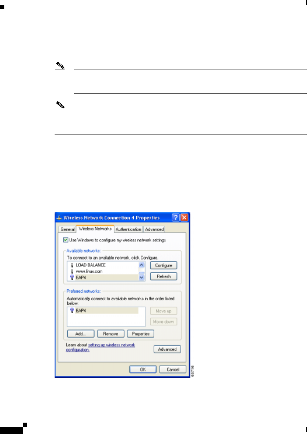
BETA DRAFT - CISCO CONFIDENTIAL
E-4
Cisco Aironet Wireless LAN Client Adapters Installation and Configuration Guide for Windows OL-1394-03
Appendix E Configuring the Client Adapter through Windows XP
Configuring the Client Adapter
Configuring the Client Adapter
Follow the steps below to configure your client adapter using Windows XP.
Note If you installed ACU but intend to use Windows XP to configure the client adapter, open
ACU and make sure the Allow Windows To Configure My Wireless Network Settings
option is selected on the Profile Manager screen.
Note These instructions assume you are using Windows XP’s classic view rather than its category
view.
Step 1 Make sure the client adapter’s driver has been installed and the client adapter is inserted into the
Windows XP device.
Step 2 Double-click My Computer, Control Panel, and Network Connections.
Step 3 Right-click Wireless Network Connection.
Step 4 Click Properties. The Wireless Network Connection Properties screen appears.
Step 5 Select the Wireless Networks tab. The following screen appears (see Figure E-1).
Figure E-1 Wireless Network Connection Properties Screen (Wireless Networks Tab)
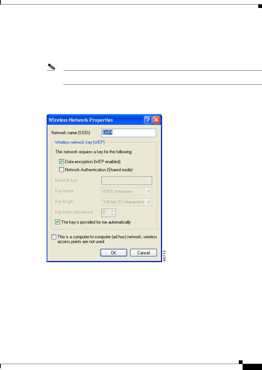
BETA DRAFT - CISCO CONFIDENTIAL
E-5
Cisco Aironet Wireless LAN Client Adapters Installation and Configuration Guide for Windows
OL-1394-03
Appendix E Configuring the Client Adapter through Windows XP Configuring the Client Adapter
Step 6 Make sure that the Use Windows to configure my wireless network settings checkbox is selected.
Step 7 Select the SSID of the access point to which you want the client adapter to associate from the list of
available networks and click Configure. If the SSID of the access point you want to use is not listed or
you are planning to operate the client adapter in an ad hoc network (a computer-to-computer network
without access points), click Add.
Note The Allow Broadcast SSID to Associate option on the access point must be enabled for the
SSID to appear in the list of available networks.
The Wireless Network Properties screen appears (see Figure E-2).
Figure E-2 Wireless Network Properties Screen
Step 8 Perform one of the following:
•If you selected an SSID from the list of available networks, make sure the SSID appears in the
Network name (SSID) field.
•If you clicked Add, enter the case-sensitive SSID of the access point to which you want the client
adapter to associate or the name of the ad hoc network in the Network name (SSID) field.
Step 9 Select the Data encryption (WEP enabled) checkbox if you are planning to use static or dynamic WEP.

BETA DRAFT - CISCO CONFIDENTIAL
E-6
Cisco Aironet Wireless LAN Client Adapters Installation and Configuration Guide for Windows OL-1394-03
Appendix E Configuring the Client Adapter through Windows XP
Configuring the Client Adapter
Step 10 Select the Network Authentication (Shared mode) checkbox if you want to use shared key, rather than
open, authentication with the access point.
Open authentication allows your client adapter, regardless of its WEP settings, to authenticate and
attempt to communicate with an access point.
Shared key authentication allows your client adapter to communicate only with access points that have
the same WEP key. Cisco recommends that shared key authentication not be used because it presents a
security risk.
Note If you are planning to use EAP-TLS authentication, do not select this checkbox. EAP-TLS
does not work with shared key authentication because shared key authentication requires the
use of a WEP key, and a WEP key is not set for EAP-TLS until after the completion of EAP
authentication.
Step 11 Follow the steps below to enter up to four WEP keys, if you are planning to use static WEP.
Note If you are planning to use EAP-TLS authentication, which uses dynamic WEP, go to Step 12.
a. Obtain the WEP key for the access point (in an infrastructure network) or other clients (in an ad hoc
network) from your system administrator and enter it in the Network key field. In order to
communicate, the client adapter must use the same WEP key as the access point or other clients.
b. Select one of the following WEP key formats:
–
ASCII characters – Specifies that the WEP key will be entered in ASCII text, which includes
alpha characters, numbers, and punctuation marks.
–
Hexadecimal digits – Specifies that the WEP key will be entered in hexadecimal characters,
which include 0-9, A-F, and a-f.
c. Select one of the following WEP key lengths:
–
104 bits (13 characters/26 digits) – You can select this option (or the 40 bits option) if your
client adapter supports 128-bit WEP.
–
40 bits (5 characters/10 digits) – You must select this option if your client adapter supports
only 40-bit WEP.
d. In the Key index (advanced) field, select the number of the WEP key you are creating (0, 1, 2, or 3).
Note The WEP key must be assigned to the same number on both the client adapter and the
access point (in an infrastructure network) or other clients (in an ad hoc network).
e. Repeat the previous steps if you want to enter another WEP key.
Step 12 Select the The key is provided for me automatically checkbox if you are planning to use EAP-TLS,
which uses dynamic WEP keys.
Step 13 Select the This is a computer-to-computer (ad hoc mode) network; wireless access points are not
used checkbox if you are planning to operate the client adapter in an ad hoc network.
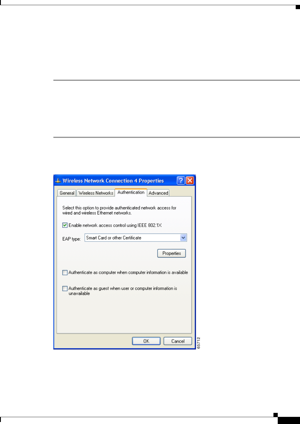
BETA DRAFT - CISCO CONFIDENTIAL
E-7
Cisco Aironet Wireless LAN Client Adapters Installation and Configuration Guide for Windows
OL-1394-03
Appendix E Configuring the Client Adapter through Windows XP Configuring the Client Adapter
Step 14 Click OK to save your settings and to add this SSID to the list of preferred networks (see Figure E-1).
The client adapter automatically attempts to associate to the network(s) in the order in which they are
listed.
Step 15 If you are planning to use EAP-TLS or EAP-MD5, follow the instructions in either the “Enabling
EAP-TLS Authentication” section on page E-7 or the “Enabling EAP-MD5 Authentication” section on
page E-9.
Enabling EAP-TLS Authentication
Follow the steps below to prepare the client adapter to use EAP-TLS authentication, provided you have
completed the initial configuration.
Step 1 Click the Authentication tab on the Wireless Network Connection Properties screen. The following
screen appears (see Figure E-3).
Figure E-3 Wireless Network Connection Properties Screen (Authentication Tab)
Step 2 Select the Enable network access control using IEEE 802.1X checkbox.
Step 3 For EAP type, select Smart Card or other Certificate.
Step 4 Click Properties. The Smart Card or other Certificate Properties screen appears (see Figure E-4).
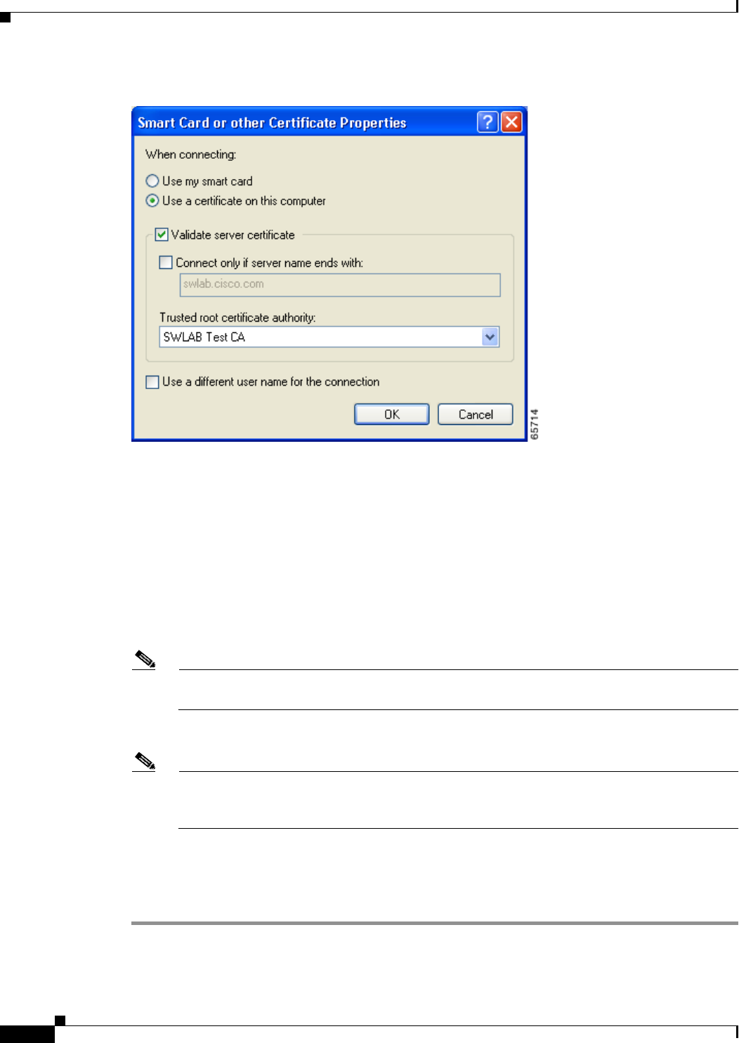
BETA DRAFT - CISCO CONFIDENTIAL
E-8
Cisco Aironet Wireless LAN Client Adapters Installation and Configuration Guide for Windows OL-1394-03
Appendix E Configuring the Client Adapter through Windows XP
Configuring the Client Adapter
Figure E-4 Smart Card or other Certificate Properties Screen
Step 5 Select the Use a certificate on this computer option.
Step 6 Select the Validate server certificate checkbox.
Step 7 Make sure that the name of the certificate authority from which the EAP-TLS certificate was
downloaded appears in the Trusted root certificate authority field.
Step 8 Click OK to save your settings. The configuration is complete.
Step 9 If a pop-up message appears above the system tray informing you that you need to accept a certificate
to begin the EAP authentication process, click the message and follow the instructions provided to accept
the certificate.
Note You should not have to accept a certificate for future authentication attempts. The same
certificate, which is tied to your login, will be used.
The client adapter should now EAP authenticate.
Note Whenever the computer reboots and you enter your Windows username and password, the
EAP authentication process begins automatically and the client adapter should EAP
authenticate.
Step 10 To verify authentication, double-click My Computer, Control Panel, and Network Connections. The
status appears to the right of your Wireless Network Connection. If the client adapter is authenticated,
the status reads, “Authentication succeeded.” The status line also indicates if the authentication attempt
fails.
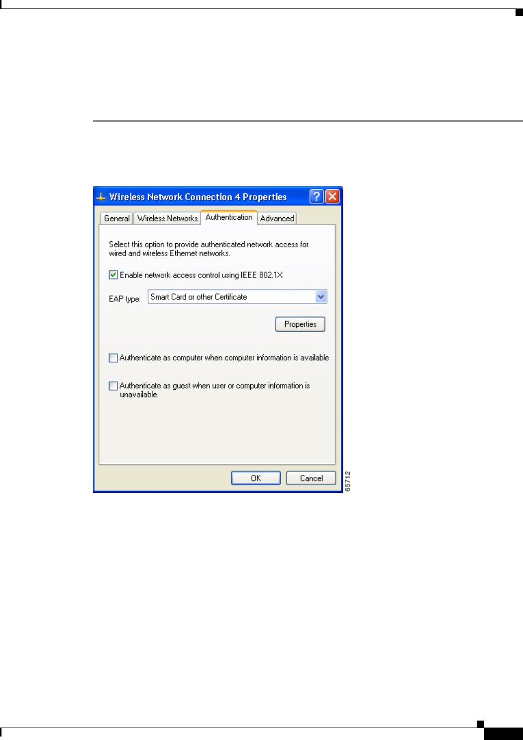
BETA DRAFT - CISCO CONFIDENTIAL
E-9
Cisco Aironet Wireless LAN Client Adapters Installation and Configuration Guide for Windows
OL-1394-03
Appendix E Configuring the Client Adapter through Windows XP Configuring the Client Adapter
Enabling EAP-MD5 Authentication
Follow the steps below to prepare the client adapter to use EAP-MD5 authentication, provided you have
completed the initial configuration.
Step 1 Click the Authentication tab on the Wireless Network Connection Properties screen. The following
screen appears (see Figure E-5).
Figure E-5 Wireless Network Connection Properties Screen (Authentication Tab)
Step 2 Select the Enable network access control using IEEE 802.1X checkbox.
Step 3 For EAP type, select MD5-Challenge.
Step 4 Click OK to save your settings. The configuration is complete, and the client adapter should attempt to
associate and EAP authenticate using MD5.
Step 5 When a pop-up message appears above the system tray informing you that you need to enter your
credentials to access the network, click the message. The Wireless Network Connection screen appears.
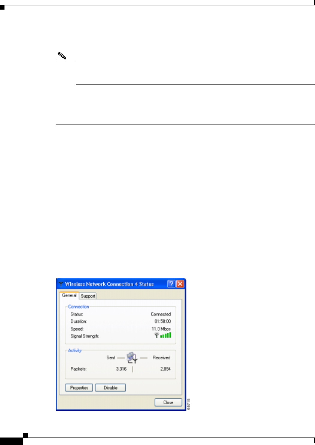
BETA DRAFT - CISCO CONFIDENTIAL
E-10
Cisco Aironet Wireless LAN Client Adapters Installation and Configuration Guide for Windows OL-1394-03
Appendix E Configuring the Client Adapter through Windows XP
Using Windows XP to Associate to an Access Point
Step 6 Enter your EAP-MD5 authentication username, password, and optional domain name (which are
registered with the RADIUS server) and click OK. The client adapter should now EAP authenticate.
Note Whenever the computer reboots and you enter your Windows username and password, the
pop-up message appears, and you must re-enter your EAP-MD5 credentials in order to EAP
authenticate.
Step 7 To verify authentication, double-click My Computer, Control Panel, and Network Connections. The
status appears to the right of your Wireless Network Connection. If the client adapter is authenticated,
the status reads, “Authentication succeeded.” The status line also indicates if the authentication attempt
fails.
Using Windows XP to Associate to an Access Point
Windows XP causes the client adapter’s driver to automatically attempt to associate to the first network
in the list of preferred networks (see Figure E-1). If the adapter fails to associate or loses association, it
automatically switches to the next network in the list of preferred networks.The adapter does not switch
networks as long as it remains associated to the access point. To force the client adapter to associate to
a different access point, you must select a different network from the list of available networks (and click
Configure and OK).
Viewing the Current Status of Your Client Adapter
To view the status of your client adapter, click the icon of the two connected computers in the Windows
system tray. The Wireless Network Connection Status screen appears (see Figure E-6).
Figure E-6 Wireless Network Connection Status Screen

F-1
Cisco Aironet Wireless LAN Client Adapters Installation and Configuration Guide for Windows
OL-1394-03
APPENDIX
F
Performing a Site Survey
This appendix explains how ACU’s site survey tool can be used when conducting a site survey.
The following topics are covered in this appendix:
•Overview, page F-2
•Specifying Signal Strength Units, page F-3
•Using Passive Mode, page F-3
•Using Active Mode, page F-7
•Forcing the Client Adapter To Reassociate, page F-14

BETA DRAFT - CISCO CONFIDENTIAL
F-2
Cisco Aironet Wireless LAN Client Adapters Installation and Configuration Guide for Windows OL-1394-03
Appendix F Performing a Site Survey
Overview
Overview
Note This appendix applies only to people who are responsible for conducting a site survey to determine
the best placement of infrastructure devices within a wireless network.
ACU’s site survey tool can assist you in conducting a site survey. The tool operates at the RF level and
is used to determine the best placement and coverage (overlap) for your network’s infrastructure devices.
During a site survey, the current status of the network is read from the client adapter and displayed four
times per second so you can accurately gauge network performance. The feedback that you receive can
help you to eliminate areas of low RF signal levels that can result in a loss of connection between the
client adapter and its associated access point (or other infrastructure device).
The site survey tool can be operated in two modes:
•Passive Mode – This is the default site survey mode. It does not initiate any RF network traffic; it
simply listens to the traffic that the client adapter hears and displays the results. Follow the
instructions in the “Using Passive Mode” section on page F-3 to activate the passive mode.
•Active Mode – This mode causes the client adapter to actively send or receive low-level RF packets
to or from its associated access point and provides information on the success rate. It also enables
you to set parameters governing how the site survey is performed (such as the data rate). Follow the
instructions in the “Using Active Mode” section on page F-7 to activate the active mode.
Guidelines
Keep the following guidelines in mind when preparing to perform a site survey:
•Perform the site survey when the RF link is functioning with all other systems and noise sources
operational.
•Execute the site survey entirely from the mobile station.
•When using the active mode, conduct the site survey with all variables set to operational values.
Additional Information
Also consider the following operating and environmental conditions when performing a site survey:
•Data rates – Sensitivity and range are inversely proportional to data bit rates. Therefore, the
maximum radio range is achieved at the lowest workable data rate, and a decrease in receiver
threshold sensitivity occurs as the radio data increases.
•Antenna type and placement – Proper antenna configuration is a critical factor in maximizing
radio range. As a general rule, range increases in proportion to antenna height.
•Physical environment – Clear or open areas provide better radio range than closed or filled areas.
Also, the less cluttered the work environment, the greater the range.

BETA DRAFT - CISCO CONFIDENTIAL
F-3
Cisco Aironet Wireless LAN Client Adapters Installation and Configuration Guide for Windows
OL-1394-03
Appendix F Performing a Site Survey Specifying Signal Strength Units
•Obstructions – A physical obstruction such as metal shelving or a steel pillar can hinder the
performance of wireless devices. Avoid placing these devices in a location where a metal barrier is
between the sending and receiving antennas.
•Building materials – Radio penetration is greatly influenced by the building material used in
construction. For example, drywall construction allows greater range than concrete blocks, and
metal or steel construction is a barrier to radio signals.
Note Refer to the Hardware Installation Guide for your infrastructure device for additional information on
factors affecting placement.
Specifying Signal Strength Units
Follow the steps below to specify how signal strength units are displayed on the site survey screens.
Step 1 Double-click the Aironet Client Utility (ACU) icon on your desktop to open ACU.
Step 2 Click the Preferences icon or select Preferences from the Options drop-down menu. The Aironet Client
Utility Preferences screen appears.
Step 3 Under Signal Strength Display Units, select one of the following options:
•Percent – Displays the signal strength as a percentage.
•dBm – Displays the signal strength in decibels with respect to milliwatts.
Note dBm can be selected only if your client adapter is using PCM/LMC/PCI card firmware
version 3.92 or greater, mini PCI card firmware version 5.0 or greater, or PC-Cardbus
firmware version 4.99 or greater.
Step 4 Click OK to save your changes.
Using Passive Mode
Step 1 Open ACU; then click the Site Survey icon or select Site Survey from the Commands drop-down menu.
The Site Survey - Passive Mode screen appears, provided a client adapter is installed in the Windows
device and is running.
Figure F-1 shows the Site Survey - Passive Mode screen with the signal strength values displayed as
percentages, and Figure F-2 shows the top of the same screen with the signal strength values displayed
in dBm.
Note The name of the current profile appears in parentheses at the top of the screen.
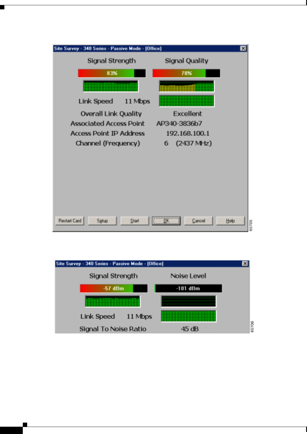
BETA DRAFT - CISCO CONFIDENTIAL
F-4
Cisco Aironet Wireless LAN Client Adapters Installation and Configuration Guide for Windows OL-1394-03
Appendix F Performing a Site Survey
Using Passive Mode
Figure F-1 Site Survey - Passive Mode Screen (with Signal Strength as a Percentage)
Figure F-2 Top of Site Survey - Passive Mode Screen (with Signal Strength in dBm)
Table F-1 interprets the information that is displayed on the Site Survey - Passive Mode screen.

BETA DRAFT - CISCO CONFIDENTIAL
F-5
Cisco Aironet Wireless LAN Client Adapters Installation and Configuration Guide for Windows
OL-1394-03
Appendix F Performing a Site Survey Using Passive Mode
Table F-1 Site Survey Passive Mode Statistics
Statistic Description
Signal Strength The signal strength for all received packets. The higher the value
and the more green the bar graph is, the stronger the signal.
The histogram below the bar graph provides a visual
interpretation of the current signal strength. Differences in signal
strength are indicated by the following colors: green (strongest),
yellow (middle of the range), and red (weakest).
Range: 0 to 100% or –95 to –45 dBm
Signal Quality
(2.4-GHz client adapters) The signal quality for all received packets. The higher the value
and the more green the bar graph is, the better the quality of the
signal.
The histogram below the bar graph provides a visual
interpretation of the current signal quality. Differences in signal
quality are indicated by the following colors: green (highest
quality), yellow (average), and red (lowest quality).
Range: 0 to 100%
Note This setting appears only for 2.4-GHz client adapters and
only if you selected signal strength to be displayed as a
percentage. See the “Specifying Signal Strength Units”
section on page F-3 for information.
Current Beacons Received
(5-GHz client adapters) The percentage of beacon packets received versus those expected
to be received. The higher the value and the more green the bar
graph is, the clearer the signal.
Example: The access point sends out 10 beacons per second, so
you would expect the client adapter to receive 50
beacon packets in 5 seconds. If it receives only 40
packets, the percentage of beacons received would be
80%.
Range: 0 to 100%
Note This setting appears only for 5-GHz client adapters (or for
2.4-GHz client adapters using firmware version less than
4.05) and only if you selected signal strength to be
displayed as a percentage. See the “Specifying Signal
Strength Units” section on page F-3 for information.

BETA DRAFT - CISCO CONFIDENTIAL
F-6
Cisco Aironet Wireless LAN Client Adapters Installation and Configuration Guide for Windows OL-1394-03
Appendix F Performing a Site Survey
Using Passive Mode
Noise Level The level of background radio frequency energy in the 2.4-GHz
or 5-GHz band. The lower the value and the more green the bar
graph is, the less background noise present.
The histogram below the bar graph provides a visual
interpretation of the current level of background noise.
Differences in background noise level are indicated by the
following colors: green (low noise), yellow (middle of the range),
and red (high noise).
Range: –100 to –45 dBm
Note This setting appears only if you selected signal strength to
be displayed in dBm. See the “Specifying Signal Strength
Units” section on page F-3 for information.
Link Speed In passive mode, the site survey tool monitors transmitted
network traffic, and the data rate reflects the rate at which the
packets are being transmitted.
The Link Speed histogram provides a visual interpretation of the
current rate at which your client adapter is transmitting packets.
Differences in link speed are indicated by the following colors:
green (fastest), yellow (middle of the range), and red (slowest).
Value: 1, 2, 5.5, or 11 Mbps (2.4-GHz client adapters);
6, 9, 12, 18, 24, 36, 48, or 54 Mbps (5-GHz client
adapters)
Overall Link Quality The client adapter’s ability to communicate with the access point.
Value: Not Associated, Poor, Fair, Good, Excellent
Note This setting appears only if you selected signal strength to
be displayed as a percentage. See the “Specifying Signal
Strength Units” section on page F-3 for information.
Signal To Noise Ratio The difference between the signal strength and the noise level.
The higher the value, the better the client adapter’s ability to
communicate with the access point.
Range: 0 to 90 dB
Note This setting appears only if you selected signal strength to
be displayed in dBm. See the “Specifying Signal Strength
Units” section on page F-3 for information.
Associated Access Point The access point to which your client adapter is associated. It is
shown only if the access point was configured with a name and
your client adapter is in infrastructure mode.
Table F-1 Site Survey Passive Mode Statistics (continued)
Statistic Description

BETA DRAFT - CISCO CONFIDENTIAL
F-7
Cisco Aironet Wireless LAN Client Adapters Installation and Configuration Guide for Windows
OL-1394-03
Appendix F Performing a Site Survey Using Active Mode
Step 2 If you want to activate the site survey active mode, go to the “Using Active Mode” section below.
Otherwise, click OK or Cancel to exit the site survey application.
Using Active Mode
Follow the steps below to activate the site survey active mode and obtain current information about your
client adapter’s ability to transmit and receive RF packets.
Step 1 From the Site Survey - Passive Mode screen (see Figure F-1), click the Setup button. The Site Survey
Active Mode Setup screen appears (see Figure F-3).
Access Point IP Address The IP address of the access point to which your client adapter is
associated. It is shown only if the access point was configured
with an IP address and your client adapter is in infrastructure
mode.
Channel (Frequency) The frequency that your client adapter is currently using as the
channel for communications.
Value: Dependent on client adapter radio and regulatory
domain
Table F-1 Site Survey Passive Mode Statistics (continued)
Statistic Description
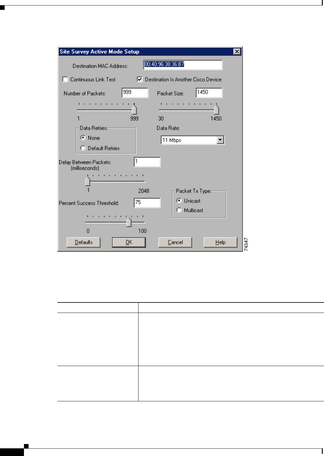
BETA DRAFT - CISCO CONFIDENTIAL
F-8
Cisco Aironet Wireless LAN Client Adapters Installation and Configuration Guide for Windows OL-1394-03
Appendix F Performing a Site Survey
Using Active Mode
Figure F-3 Site Survey Active Mode Setup Screen
Table F-2 lists and describes the parameters that affect how the site survey is performed. Follow the
instructions in the table to set any parameters.
Table F-2 Site Survey Active Mode Parameters
Parameter Description
Destination MAC Address The MAC address of the access point (in infrastructure mode) or other
clients (in ad hoc mode) that will be used in the test.
Default: The MAC address of the access point (in infrastructure mode)
to which your client adapter is associated
Note During the test, the client adapter will not roam to other access
points so that the size of a single cell can be determined.
Continuous Link Test Selecting this checkbox causes the test to run until you click OK or
Stop. The test loops repeatedly for the number of packets specified in
the Number of Packets field.
Default: Deselected

BETA DRAFT - CISCO CONFIDENTIAL
F-9
Cisco Aironet Wireless LAN Client Adapters Installation and Configuration Guide for Windows
OL-1394-03
Appendix F Performing a Site Survey Using Active Mode
Destination Is Another
Cisco/Aironet Device Selecting this checkbox indicates that the device you named in the
Destination MAC Address field is a Cisco Aironet access point (in
infrastructure mode) or client (in ad hoc mode). In this case, packets sent
to the client from the Cisco Aironet device contain additional information,
such as lost to source, lost to target, and percent retries, and this
information is displayed in the Site Survey - Active screen.
If the device specified in the Destination MAC Address field is not a
Cisco Aironet device, do not select this checkbox. In this case, the test
sends out loopback packets, which originate from and return to the
client adapter.
Default: Selected
Number of Packets The number of packets that will be sent during the test.
Range: 1 to 999
Default: 100
Packet Size The size of the packets that will be sent during the test. Select a size that
will be typical during normal system use.
Range: 30 to 1450
Default: 512
Data Retries The number of times a transmission will be retried if an
acknowledgment (Ack) is not returned by the destination device.
Default: None
Retry Value Description
None No retries will occur.
Default Retries The firmware’s default value for retries
(16) will be used.
Data Rate The bit rate at which packets will be transmitted. Rate shifting will not
occur during the test because the echo test built into the radio firmware
does not support it.
Value: 1, 2, 5.5, or 11 Mbps (2.4-GHz client adapters);
6, 9, 12, 18, 24, 36, 48, or 54 Mbps (5-GHz client adapters)
Default: 11 Mbps (2.4-GHz client adapters);
54 Mbps (5-GHz client adapters)
Table F-2 Site Survey Active Mode Parameters (continued)
Parameter Description

BETA DRAFT - CISCO CONFIDENTIAL
F-10
Cisco Aironet Wireless LAN Client Adapters Installation and Configuration Guide for Windows OL-1394-03
Appendix F Performing a Site Survey
Using Active Mode
Step 2 After setting any parameters, click OK to save the settings. The Site Survey - Passive Mode screen
appears (see Figure F-1).
Step 3 Click the Start button to run the site survey test. The Site Survey - Active Mode screen appears.
Figure F-4 shows the Site Survey - Active Mode screen with the signal strength values displayed as
percentages, and Figure F-5 shows the top of the same screen with the signal strength values displayed
in dBm.
Delay Between Packets The delay (in milliseconds) between successive transmissions.
Range: 1 to 2048 ms
Default: 50 ms
Percent Success Threshold The percentage of packets that are not lost.
This parameter controls the red line on the Percent Successful
histogram. Percentages greater than or equal to this value are displayed
as green bars; percentages below this value are displayed as yellow
bars.
Range: 0 to 100%
Default: 75
Packet Tx Type The packet type that will be transmitted during the test.
Default: Unicast
Packet Type Description
Unicast When unicast packets are used, the system
expects to receive an acknowledgment
from the destination, and retries can occur.
Multicast When multicast packets are used, no
packet retries occur during the test.
Table F-2 Site Survey Active Mode Parameters (continued)
Parameter Description
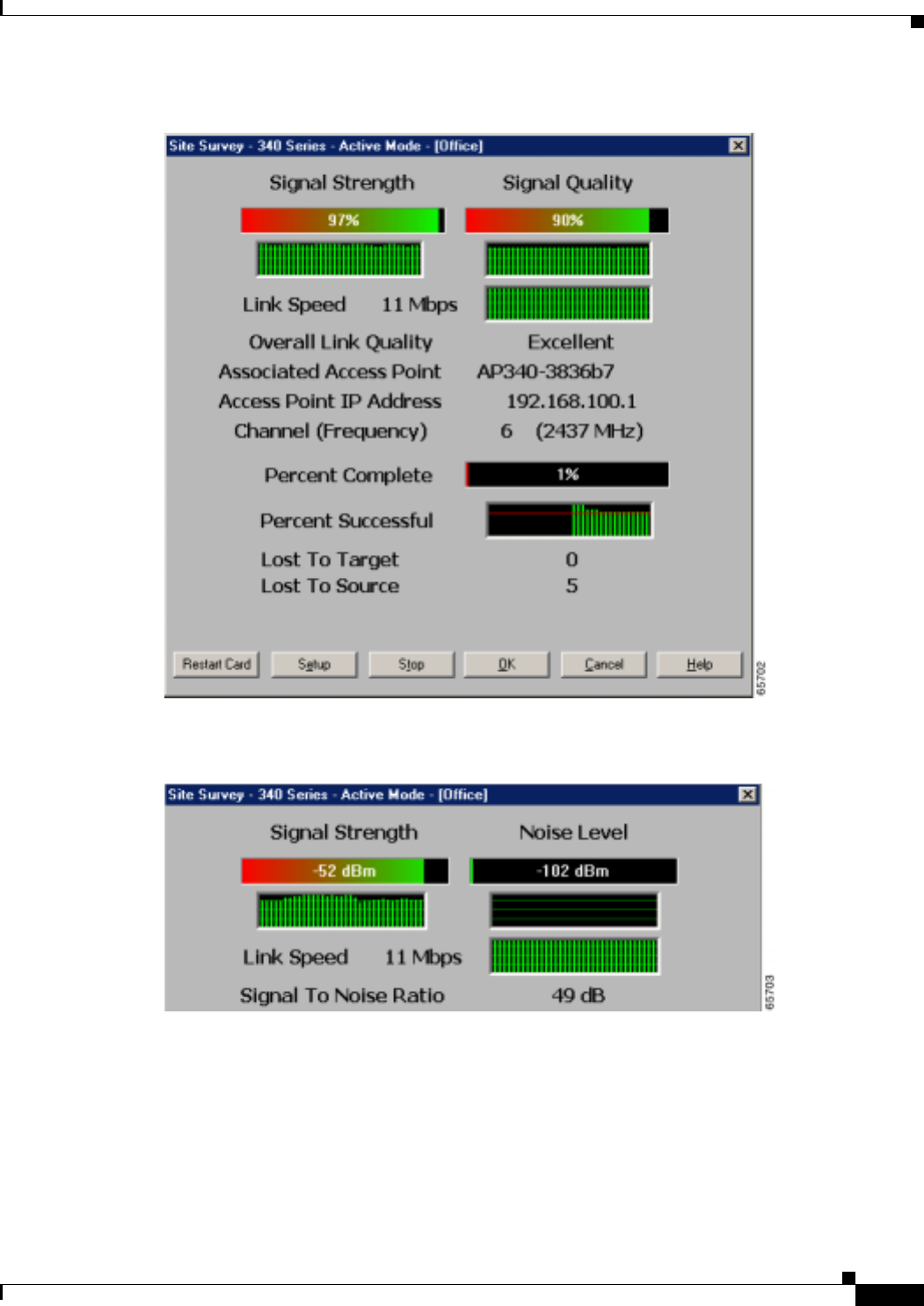
BETA DRAFT - CISCO CONFIDENTIAL
F-11
Cisco Aironet Wireless LAN Client Adapters Installation and Configuration Guide for Windows
OL-1394-03
Appendix F Performing a Site Survey Using Active Mode
Figure F-4 Site Survey - Active Mode Screen (with Signal Strength as a Percentage)
Figure F-5 Top of Site Survey - Active Mode Screen (with Signal Strength in dBm)
Table F-3 interprets the information that is displayed on the Site Survey - Active Mode screen while the
site survey test is running.

BETA DRAFT - CISCO CONFIDENTIAL
F-12
Cisco Aironet Wireless LAN Client Adapters Installation and Configuration Guide for Windows OL-1394-03
Appendix F Performing a Site Survey
Using Active Mode
Table F-3 Site Survey Active Mode Statistics
Statistic Description
Signal Strength The signal strength for all received packets. The higher the value
and the more green the bar graph is, the stronger the signal.
The histogram below the bar graph provides a visual
interpretation of the current signal strength. Differences in signal
strength are indicated by the following colors: green (strongest),
yellow (middle of the range), and red (weakest).
Range: 0 to 100% or –95 to –45 dBm
Signal Quality
(2.4-GHz client adapters) The signal quality for all received packets. The higher the value
and the more green the bar graph is, the better the quality of the
signal.
The histogram below the bar graph provides a visual
interpretation of the current signal quality. Differences in signal
quality are indicated by the following colors: green (highest
quality), yellow (average), and red (lowest quality).
Range: 0 to 100%
Note This setting appears only for 2.4-GHz client adapters and
only if you selected signal strength to be displayed as a
percentage. See the “Specifying Signal Strength Units”
section on page F-3 for information.
Current Beacons Received
(5-GHz client adapters) The percentage of beacon packets received versus those expected
to be received. The higher the value and the more green the bar
graph is, the clearer the signal.
Example: The access point sends out 10 beacons per second, so
you would expect the client adapter to receive 50
beacon packets in 5 seconds. If it receives only 40
packets, the percentage of beacons received would be
80%.
Range: 0 to 100%
Note This setting appears only for 5-GHz client adapters (or for
2.4-GHz client adapters using firmware version less than
4.05) and only if you selected signal strength to be
displayed as a percentage. See the “Specifying Signal
Strength Units” section on page F-3 for information.
Link Speed The rate at which your client adapter is transmitting packets to or
from its associated access point.
The Link Speed histogram provides a visual interpretation of the
current rate at which your client adapter is transmitting packets.
Differences in link speed are indicated by the following colors:
green (fastest), yellow (middle of the range), and red (slowest).
Value: 1, 2, 5.5, or 11 Mbps (2.4-GHz client adapters);
6, 9, 12, 18, 24, 36, 48, or 54 Mbps (5-GHz client
adapters)

BETA DRAFT - CISCO CONFIDENTIAL
F-13
Cisco Aironet Wireless LAN Client Adapters Installation and Configuration Guide for Windows
OL-1394-03
Appendix F Performing a Site Survey Using Active Mode
Step 4 When you click the Stop button or when the Percent Complete reaches 100%, the active mode changes
back to the passive mode.
Step 5 Click OK or Cancel to exit the site survey application.
Overall Link Quality The client adapter’s ability to communicate with the access point.
Value: Not Associated, Poor, Fair, Good, Excellent
Note This setting appears only if you selected signal strength to
be displayed as a percentage. See the “Specifying Signal
Strength Units” section on page F-3 for information.
Signal To Noise Ratio The difference between the signal strength and the noise level.
The higher the value, the better the client adapter’s ability to
communicate with the access point.
Range: 0 to 90 dB
Note This setting appears only if you selected signal strength to
be displayed in dBm. See the “Specifying Signal Strength
Units” section on page F-3 for information.
Associated Access Point The access point to which your client adapter is associated. It is
shown only if the access point was configured with a name and
the client adapter is in infrastructure mode.
Access Point IP Address The IP address of the access point to which your client adapter is
associated. It is shown only if the access point was configured
with an IP address and the client adapter is in infrastructure mode.
Channel (Frequency) The frequency that your client adapter is currently using as the
channel for communications.
Value: Dependent on client adapter radio and regulatory
domain
Percent Complete The percentage of packets that have been transmitted based on the
number specified in the Number of Packets field.
Percent Successful The percentage of packets that were transmitted successfully.
The Percent Successful histogram provides a visual interpretation
of the percentage of packets that are not lost. The value you set
for the Percent Success Threshold is indicated by the red line.
Percentages greater than or equal to this value are displayed as
green bars; percentages below this value are displayed as yellow
bars.
Note Refer to the Percent Success Threshold parameter in
Table F-2 for more information.
Lost To Target The number of packets that were not transmitted successfully to
the access point.
Lost To Source The number of packets that were not received successfully from
the access point.
Table F-3 Site Survey Active Mode Statistics (continued)
Statistic Description

BETA DRAFT - CISCO CONFIDENTIAL
F-14
Cisco Aironet Wireless LAN Client Adapters Installation and Configuration Guide for Windows OL-1394-03
Appendix F Performing a Site Survey
Forcing the Client Adapter To Reassociate
Forcing the Client Adapter To Reassociate
The client adapter will attempt to maintain its association to an access point for as long as it can.
Therefore if you are on a fringe area while conducting a site survey, you may want to reinitialize (or
restart) the client adapter in an attempt to force it to disassociate from the access point to which it is
currently associated and reassociate to another access point.
Note Restarting the client adapter may cause you to lose your wireless network connection.
Follow the steps below to attempt to force the client adapter to disassociate from its current access point
and reassociate to another during a site survey.
Step 1 Click the Restart Card button on the bottom of the Site Survey screen.
Step 2 When prompted to confirm your decision, click Yes. The driver stops the client adapter’s radio, writes
the configuration (although no parameter settings have been changed), and restarts the radio.

BETA DRAFT - CISCO CONFIDENTIAL
GL-1
Cisco Aironet Wireless LAN Client Adapters Installation and Configuration Guide for Windows
OL-1394-03
GLOSSARY
802.1X Also called 802.1X for 802.11. 802.1X is the new standard for wireless LAN security, as defined by the
Institute of Electrical and Electronics Engineers (IEEE). An access point that supports 802.1X and its
protocol, Extensible Authentication Protocol (EAP), acts as the interface between a wireless client and an
authentication server, such as a Remote Authentication Dial-In User Service (RADIUS) server, to which the
access point communicates over the wired network.
802.11 The IEEE standard that specifies carrier sense media access control and physical layer specifications
for 1- and 2-megabit-per-second (Mbps) 2.4-GHz wireless LANs.
802.11a The IEEE standard that governs the deployment of 5-GHz OFDM systems. It specifies the
implementation of the physical layer for wireless UNII bands (see UNII, UNII 1, and UNII 2) and
provides four channels per 100 MHz of bandwidth.
802.11b The IEEE standard that specifies carrier sense media access control and physical layer specifications
for 5.5- and 11-Mbps 2.4-GHz wireless LANs.
A
Access Point A wireless LAN data transceiver that uses radio waves to connect a wired network with wireless
stations.
Ad Hoc Network A wireless network composed of stations without access points.
Alphanumeric A set of characters that contains both letters and numbers.
Associated A station is configured properly to allow it to wirelessly communicate with an access point.
B
Bandwidth Specifies the amount of the frequency spectrum that is usable for data transfer. It identifies the
maximum data rate that a signal can attain on the medium without encountering significant power loss.
BPSK Binary phase shift keying. A modulation technique used by IEEE 802.11-compliant wireless LANs for
transmission at 1 Mbps.
Broadcast key
rotation A security feature for use with dynamic WEP keys. If your client adapter uses LEAP or EAP-TLS
authentication and you enable this feature, the access point changes the dynamic broadcast WEP key
that it provides at the interval you select.

BETA DRAFT - CISCO CONFIDENTIAL
Glossary
GL-2
Cisco Aironet Wireless LAN Client Adapters Installation and Configuration Guide for Windows OL-1394-03
C
CCK Complementary code keying. A modulation technique used by IEEE 802.11b-compliant wireless LANs
for transmission at 5.5 and 11 Mbps.
Client A radio device that uses the services of an access point to communicate wirelessly with other devices
on a local area network.
CSMA Carrier sense multiple access. A wireless LAN media access method specified by the IEEE 802.11
specification.
Cyclic Redundancy
Check (CRC) A method of checking for errors in a received packet.
D
Data Rates The range of data transmission rates supported by a device. Data rates are measured in megabits per
second (Mbps).
dBi A ratio of decibels to an isotropic antenna that is commonly used to measure antenna gain. The greater
the dBi value, the higher the gain and the more acute the angle of coverage.
DHCP Dynamic Host Configuration Protocol. A protocol available with many operating systems that
automatically issues IP addresses within a specified range to devices on the network. The device retains
the assigned address for a specific administrator-defined period.
Dipole A type of low-gain (2.2-dBi) antenna consisting of two (often internal) elements.
DSSS Direct-sequence spread spectrum. A type of spread spectrum radio transmission that spreads its signal
continuously over a wide frequency band.
Duplicate Packets Packets that were received twice because an acknowledgement got lost and the sender retransmitted the
packet.
E
EAP Extensible Authentication Protocol. EAP is the protocol for the optional IEEE 802.1X wireless LAN
security feature. An access point that supports 802.1X and EAP acts as the interface between a wireless
client and an authentication server, such as a Remote Authentication Dial-In User Service (RADIUS) server,
to which the access point communicates over the wired network.
Ethernet The most widely used wired local area network. Ethernet uses carrier sense multiple access (CSMA)
to allow computers to share a network and operates at 10, 100, or 1000 megabits per second (Mbps),
depending on the physical layer used.

BETA DRAFT - CISCO CONFIDENTIAL
Glossary
GL-3
Cisco Aironet Wireless LAN Client Adapters Installation and Configuration Guide for Windows
OL-1394-03
.
F
File Server A repository for files so that a local area network can share files, mail, and programs.
Firmware Software that is programmed on a memory chip and kept in a computer’s semi-permanent memory.
Fragmentation
Threshold The size at which packets will be fragmented and transmitted a piece at a time instead of all at once.
The setting must be within the range of 64 to 2312 bytes.
Full Duplex A means of communication whereby each node receives and transmits simultaneously (two-way). See
also Half Duplex.
G
Gateway A device that connects two otherwise incompatible networks together.
GHz Gigahertz. One billion cycles per second. A unit of measure for frequency.
H
Half Duplex A means of communication whereby each node receives and transmits in turn (one-way). See also Full
Duplex.
Hexadecimal A set of characters consisting of ten numbers and six letters (0-9, A-F, and a-f).
I
IEEE Institute of Electrical and Electronic Engineers. A professional society serving electrical engineers
through its publications, conferences, and standards development activities. The body responsible for
the Ethernet 802.3 and wireless LAN 802.11 specifications.
Infrastructure The wired Ethernet network.
Infrastructure
Device A device that connects client adapters to a wired LAN, such as an access point, bridge, or base station.
IP Address The Internet Protocol (IP) address of a station.
IP Subnet Mask The number used to identify the IP subnetwork, indicating whether the IP address can be recognized
on the LAN or if it must be reached through a gateway.
Isotropic An antenna that radiates its signal 360 degrees both vertically and horizontally in a perfect sphere.

BETA DRAFT - CISCO CONFIDENTIAL
Glossary
GL-4
Cisco Aironet Wireless LAN Client Adapters Installation and Configuration Guide for Windows OL-1394-03
L
LEAP LEAP, or EAP-Cisco Wireless, is the 802.1X authentication type that is available for use with operating
systems that do not have built-in EAP support. Support for LEAP is provided in the client adapter’s
firmware and the Cisco software that supports it, rather than in the operating system. With LEAP, a
username and password are used by the client adapter to perform mutual authentication with the
RADIUS server through an access point.
M
MAC Address The Media Access Control (MAC) address is a unique serial number assigned to a networking device
by the manufacturer.
MIC Message integrity check. MIC prevents bit-flip attacks on encrypted packets. During a bit-flip attack,
an intruder intercepts an encrypted message, alters it slightly, and retransmits it, and the receiver
accepts the retransmitted message as legitimate. The client adapter’s driver and firmware must support
MIC functionality, and MIC must be enabled on the access point.
Modulation Any of several techniques for combining user information with a transmitter’s carrier signal.
Multicast Packets Packets transmitted to multiple stations.
Multipath The echoes created as a radio signal bounces off of physical objects.
O
OFDM Orthogonal frequency division multiplexing. A multicarrier modulation method for broadband wireless
communications.
Overrun Packets Packets that were discarded because the access point had a temporary overload of packets to handle.
P
Packet A basic message unit for communication across a network. A packet usually includes routing
information, data, and sometimes error detection information.
Q
QPSK Quadruple phase shift keying. A modulation technique used by IEEE 802.11-compliant wireless LANs
for transmission at 2 Mbps.

BETA DRAFT - CISCO CONFIDENTIAL
Glossary
GL-5
Cisco Aironet Wireless LAN Client Adapters Installation and Configuration Guide for Windows
OL-1394-03
R
Radio Channel The frequency at which a radio operates.
Range A linear measure of the distance that a transmitter can send a signal.
Receiver Sensitivity A measurement of the weakest signal a receiver can receive and still correctly translate it into data.
RF Radio frequency. A generic term for radio-based technology.
Roaming A feature of some access points that allows users to move through a facility while maintaining an
unbroken connection to the LAN.
RP-TNC A connector type unique to Cisco Aironet radios and antennas. Part 15.203 of the FCC rules covering
spread spectrum devices limits the types of antennas that may be used with transmission equipment. In
compliance with this rule, Cisco Aironet, like all other wireless LAN providers, equips its radios and
antennas with a unique connector to prevent attachment of non-approved antennas to radios.
RTS Threshold The packet size at which an access point will issue a request to send (RTS) before sending the packet.
S
Spread Spectrum A radio transmission technology that spreads the user information over a much wider bandwidth than
otherwise required in order to gain benefits such as improved interference tolerance and unlicensed
operation.
SSID Service set identifier. A unique identifier that stations must use to be able to communicate with an
access point. The SSID can be any alphanumeric entry up to a maximum of 32 characters.
T
TKIP Temporal Key Integrity Protocol. Also referred to as WEP key hashing. A security feature that defends
against an attack on WEP in which the intruder uses the initialization vector (IV) in encrypted packets
to calculate the WEP key. TKIP removes the predictability that an intruder relies on to determine the
WEP key by exploiting IVs.
Transmit Power The power level of radio transmission.
U
Unicast Packets Packets transmitted in point-to-point communication.
UNII Unlicensed National Information Infrastructure. An FCC regulatory domain for 5-GHz wireless
devices. UNII bands are 100 MHz wide and divided into four channels when using 802.11a OFDM
modulation.

BETA DRAFT - CISCO CONFIDENTIAL
Glossary
GL-6
Cisco Aironet Wireless LAN Client Adapters Installation and Configuration Guide for Windows OL-1394-03
UNII 1 A UNII band dedicated to in-building wireless LAN applications. UNII 1 is located at 5.15 to 5.25 GHz
and allows for a maximum transmit power of 40 mW (or 16 dBm) with an antenna up to 6 dBi. UNII 1
regulations require a nonremovable, integrated antenna.
UNII 2 A UNII band dedicated to in-building wireless LAN applications. UNII 2 is located at 5.25 to 5.35 GHz
and allows for a maximum transmit power of 200 mW (or 23 dBm) with an antenna up to 6 dBi. UNII
2 regulations allow for an auxiliary, user-installable antenna.
W
WEP Wired Equivalent Privacy. An optional security mechanism defined within the 802.11 standard
designed to make the link integrity of wireless devices equal to that of a cable.
Workstation A computing device with an installed client adapter.

BETA DRAFT - CISCO CONFIDENTIAL
IN-1
Cisco Aironet Wireless LAN Client Adapters Installation and Configuration Guide for Windows
OL-1394-03
INDEX
Numerics
802.1X
authentication types
in ACU 5-22
in Windows XP E-3
defined 5-22, E-2
A
About Aironet Client Utility 8-21
About icon 8-21
access point
currently associated to 7-10
in wireless infrastructure 1-9
IP address
current 7-10
in link test 7-19
in site survey active mode F-13
in site survey passive mode F-7
MAC address
current 7-10
in link test 7-21
in site survey active mode F-8
specifying 5-16
mismatches 7-14
name
current 7-10
in link test 7-21
in site survey active mode F-13
in site survey passive mode F-6
problems
associating to 9-7
authenticating to 9-8
role in wireless network 1-7
security settings 5-25 to 5-26
Access Point Authentication parameter 5-27
Ack packets
number received 7-16
number transmitted 7-15
ACU
See Aironet Client Utility (ACU)
ad hoc network
defined E-5
parameters 5-17 to 5-20
selecting in ACU 5-6
selecting in Windows XP E-6
wireless LAN configuration 1-8
Advanced (Ad Hoc) screen 5-17
Advanced (Infrastructure) screen 5-14
advanced ad hoc parameters
described 5-2, 5-17
setting 5-17 to 5-20
advanced infrastructure parameters
described 5-2, 5-13
setting 5-13 to 5-16
aged packets 7-14, 7-16
Aironet Client Utility (ACU)
About icon 8-21
accessing help 9-15
compatibility with driver and firmware 3-16
described 1-5 to 1-7
determining latest version 3-2
determining version of 8-21

BETA DRAFT - CISCO CONFIDENTIAL
Index
IN-2
Cisco Aironet Wireless LAN Client Adapters Installation and Configuration Guide for Windows OL-1394-03
exiting 8-19
feature comparison to Windows XP 3-15
icon
adding to desktop 3-18
deleting from desktop 8-25
using to open ACU 3-19, 4-2, 8-18
installation program settings, modifying 8-19 to 8-20
installing 3-16 to 3-19, 9-3
opening 4-2, 8-18
overview 1-6
Properties screens
overview 5-2
parameters missing 9-8
screens, buttons described 1-7
uninstalling 8-24
upgrading 8-22 to 8-23
verifying installation 3-19
Aironet Client Utility Preferences screen 4-8, 7-3
Aironet Client Utility screen 1-6
Allow Association To Mixed Cells parameter 5-21
Allow Non-Administrator Users to use ACU to modify
profiles parameter
in ACU 4-8
in ACU installation program 3-18, 8-20, 8-23
Allow Saved LEAP User Name and Password parameter,
in ACU installation program 3-18, 8-20, 8-22
Allow Windows To Configure My Wireless Network
Settings option 4-5
antenna
described 1-4
gains D-4 to D-5
mode currently being used 7-8
placement F-2
specifications A-5
Antenna Mode (Receive) parameter
ad hoc mode 5-18
infrastructure mode 5-15
Antenna Mode (Transmit) parameter
ad hoc mode 5-18
infrastructure mode 5-15
Apply button, function 1-7
association
rejections 7-14
timeouts 7-14
audience of document xii
authentication
process 5-23, E-3
rejections 7-14
timeouts 7-14
type, status of 7-8
Automatically Prompt for LEAP User Name and Password
option 5-30
auto profile selection, using 4-4
B
beacon packets
number received 7-13
number transmitted 7-15
beacon period, status of 7-10
Beacon Period parameter 5-20
beacons received
current 7-11, 7-22, F-5, F-12
in site survey passive mode F-5
boot block firmware, current version of 7-6
broadcast key rotation
described 5-25
setting on client and access point 5-26
broadcast packets
number received 7-13
number transmitted 7-15
broadcast SSIDs 5-4, E-5
bytes
number received 7-13
number transmitted 7-15

BETA DRAFT - CISCO CONFIDENTIAL
Index
IN-3
Cisco Aironet Wireless LAN Client Adapters Installation and Configuration Guide for Windows
OL-1394-03
C
CAM
See Constantly Awake Mode (CAM)
Canadian compliance statement C-3
Cancel button, function 1-7
Card and Socket Services 2-4
carrier/correlation (Car/Cor) 5-12
caution, defined xiii
channel
current 7-9
determining if clear 5-12
in site survey active mode F-13
in site survey passive mode F-7
Channel parameter 5-10
channels, supported by regulatory domains D-2, D-3
channel set, for which client adapter is configured 7-8
Clear Channel Assessment parameter 5-12
client name 7-8
Client Name parameter 5-4
client utility
See Aironet Client Utility (ACU)
clock, setting to display seconds 1-6
collisions, multiple/single 7-15
Commands drop-down menu 6-9
configuring client adapter
deciding between ACU and Windows XP 3-15
in ACU 5-1 to 5-34
in Windows XP E-4 to E-10
Constantly Awake Mode (CAM) 5-5
Contents ACU menu option 9-15
Continuous Link Test parameter
in RF link test 7-19
in site survey active mode F-8
conventions of document xiii to xiv
CRC error
in packet 7-13
in PLCP header 7-13
Create ACU Icon on your Desktop parameter, in ACU
installation program 3-18, 8-20, 8-23
CTS packets
number received 7-16
number transmitted 7-15
D
data rate
for which client adapter is configured 7-9
mismatches 7-14
specifications A-4
when performing a site survey F-2
Data Rate parameter
in RF network 5-8
in site survey active mode F-9
Data Retries parameter
in RF network 5-13
in site survey active mode F-9
dBm
signal strength units in site survey F-3
signal strength units on Status and Linktest screens 7-4
declarations of conformity
European community, Switzerland, Norway, Iceland,
and Liechtenstein C-4 to C-5
FCC C-2
RF exposure C-6
Defaults button, function 1-7
default values, displaying 1-7
Delay Between Packets parameter F-10
Destination Is Another Cisco/Aironet Device
parameter F-9
Destination MAC Address parameter F-8
diagnostic tools
overview 7-2
setting parameters 7-2 to 7-4
using 7-4 to 7-22
dipole antenna 1-4, B-3
Display Seconds on Clock parameter 1-6

BETA DRAFT - CISCO CONFIDENTIAL
Index
IN-4
Cisco Aironet Wireless LAN Client Adapters Installation and Configuration Guide for Windows OL-1394-03
diversity antenna 1-4
diversity mode 5-15, 5-18
document
audience xii
conventions xiii to xiv
organization xii to xiii
purpose xii
documentation
CD-ROM xv
domain name
including in Windows login 5-31
specifying for saved user name and password 5-30
driver
compatibility with ACU and firmware 3-16
current version of 7-6
described 1-5
determining latest version 3-2
determining version of 8-7
installation overview 3-3
installing 3-3 to 3-16
uninstalling 8-13 to 8-18
upgrading 8-8 to 8-12
verifying installation 3-19
duplicate packets, number received 7-13
dynamic WEP keys, overview 5-22 to 5-24, E-2 to E-3
E
EAP authentication
overview 5-22 to 5-24, 6-2, E-2 to E-3
using 6-1 to 6-13
EAP-Cisco Wireless
See LEAP authentication
EAP-MD5 authentication
authenticating after a reboot/logoff 6-13
authenticating after profile selection/card
insertion 6-12
described 5-23 to 5-24, E-3
disabling 5-34
enabling
in Windows XP E-9 to E-10
through ACU 5-31 to 5-33
RADIUS servers supported 5-23, E-3
setting on client and access point 5-26
software supported 5-31
EAP-TLS authentication
authenticating after a reboot/logoff 6-12
authenticating after profile selection/card
insertion 6-12
described 5-23 to 5-24, E-3
disabling 5-34
enabling
in Windows XP E-7 to E-8
through ACU 5-31 to 5-33
RADIUS servers supported 5-23, E-3
setting on client and access point 5-25
software supported 5-31
EIRP, maximum 1-4, D-4 to D-5
energy detect (ED) 5-12
error messages 9-9 to 9-15
errors
MAC CRC 7-13
overrun 7-13
PLCP 7-13
F
Fast PSP 5-5
FCC
declaration of conformity statement C-2 to C-3
safety compliance statement 2-2
firmware
802.1x draft standards 5-28, 8-5
compatibility with ACU and driver 3-16
current version of 7-6
described 1-5
determining version of 8-5
upgrading 8-5 to 8-7

BETA DRAFT - CISCO CONFIDENTIAL
Index
IN-5
Cisco Aironet Wireless LAN Client Adapters Installation and Configuration Guide for Windows
OL-1394-03
forcing client adapter to reassociate F-14
fragmented packets 5-13
Fragment Threshold parameter 5-13
frequencies D-2, D-3
frequency 5-10
currently being used 7-9
in site survey active mode F-13
in site survey passive mode F-7
H
hardware components of client adapter 1-3 to 1-4
Help
button, function 1-7
drop-down menu 9-15
icon 9-15
help, ACU 9-15
history of RF performance, displayed 7-4
host-based EAP
authenticating after a reboot/logoff 6-12
described 5-23
disabling 5-34
enabling 5-31 to 5-33
software supported 5-31
Host Based EAP option 5-31
host devices 2-4
I
I/O range 9-4
Include Profile in Auto Profile Selection parameter 4-3
Include Windows Login Domain With User Name
parameter 5-31
infrastructure device, defined 1-3
infrastructure network
parameters 5-13 to 5-16
selecting in ACU 5-6
wireless LAN configuration 1-9
inserting client adapter 8-2 to 8-4
interference 2-5
interrupt request (IRQ) 9-4
introduction to client adapters 1-2 to 1-3
IP address
of access point in link test 7-19
of access point in site survey active mode F-13
of access point in site survey passive mode F-7
of associated access point 7-10
of client adapter 7-8
J
Japan, guidelines for operating client adapters C-6
L
LEAP authentication
authenticating after a reboot/logoff
with automatically prompted login 6-5 to 6-6
with manually prompted login 6-8 to 6-10
with saved username and password 6-11
with Windows username and password 6-3 to 6-4
authenticating after profile selection/card insertion
with automatically prompted login 6-4 to 6-5
with manually prompted login 6-8
with saved username and password 6-10
with Windows username and password 6-2
authenticating after your LEAP credentials expire
with automatically prompted login 6-7
with manually prompted login 6-10
with saved username and password 6-11
with Windows username and password 6-4
described 5-22, 5-23
disabling 5-34
enabling 5-28 to 5-31
RADIUS servers supported 5-22
setting on client and access point 5-25

BETA DRAFT - CISCO CONFIDENTIAL
Index
IN-6
Cisco Aironet Wireless LAN Client Adapters Installation and Configuration Guide for Windows OL-1394-03
stages of 6-2
supported software 5-28
LEAP Authentication Timeout Value parameter 5-31
LEAP login screen 6-6
appearing before Windows login screen 9-9
displayed 6-5, 6-8, 6-9
LEAP option 5-29
LEAP parameter, in ACU installation program 3-17, 8-20,
8-22
LEAP Settings screen 5-29
LEDs
described 1-4
interpreting 9-2 to 9-3
link quality
in link test 7-22
in site survey active mode F-13
in site survey passive mode F-6
overall 7-11
link speed
currently being used 7-8
in link test 7-21
in site survey active mode F-12
in site survey passive mode F-6
Link Status Meter
ACU menu option 7-16
icon 7-16
screen 7-17
link status meter, viewing 7-16 to 7-17
Linktest
ACU menu option 7-18
screen 7-19, 7-20
linktest, statistics 7-21
Link Test icon 7-18
LM card
antenna 1-4, 5-15, 5-18
described 1-2
Load Firmware icon 8-6
Load New Firmware ACU menu option 8-6
long radio headers, using 5-9
M
MAC address
of access point, specifying 5-16
of access point in link test 7-21
of access point in site survey active mode F-8
of associated access point 7-10
of client adapter 7-8
MAC CRC errors 7-13
Manually Prompt for LEAP User Name and Password
option 5-30
Max Power Savings
See Max PSP
Max PSP 5-5
message integrity check (MIC)
described 5-24, 7-7
setting on client and access point 5-26
statistics 7-14 to 7-15
status of 7-7
microcellular network 1-9
Microsoft hot fixes
described 9-9
uninstalling 8-26
mini PCI card
antenna 1-4, 5-15, 5-18
described 1-2
losing association upon resuming from suspend
mode 9-8
multicast packets
in site survey active mode F-10
number received 7-13
number transmitted 7-15
N
network
configurations 1-7 to 1-9
problems connecting to 9-8

BETA DRAFT - CISCO CONFIDENTIAL
Index
IN-7
Cisco Aironet Wireless LAN Client Adapters Installation and Configuration Guide for Windows
OL-1394-03
security parameters
described 5-2, 5-20
setting 5-20 to 5-34
type, current 7-9
network login screen 6-6
Network Security screen 5-20
Network Security Type parameter 5-26, 5-29, 5-31, 5-34
Network Type parameter 5-6
noise level
current 7-11
in link test 7-22
in site survey passive mode F-6
No Network Connection Unless User is Logged In
parameter 5-31
note, defined xiii
Number of Packets parameter
in link test 7-19
in site survey active mode F-9
O
OK button, function 1-7
open authentication 5-27, E-6
Open window 8-7
Options drop-down menu 1-6, 4-8, 7-2, F-3
organization of document xii to xiii
overrun errors 7-13
P
package contents 2-3
packets
Ack 7-15
aged 7-14, 7-16
beacon 5-20, 7-10, 7-13, 7-15
broadcast 7-13, 7-15
CTS 7-15, 7-16
duplicate 7-13
fragmented 5-13
linktest statistics 7-21
multicast 7-13, 7-15, F-10
RTS 5-16, 5-19, 7-15
site survey active mode statistics F-12 to F-13
site survey passive mode statistics F-5 to F-7
statistics 7-13 to 7-16
unicast 7-13, 7-15
with MIC 7-14 to 7-15
Packet Size parameter 7-19, F-9
Packet Tx Type parameter F-10
PC card
antenna 1-4, 5-15, 5-18
described 1-2
inserting 8-2 to 8-3
removing 8-4
PC-Cardbus card
antenna 1-4
described 1-2
inserting 8-2 to 8-3
removing 8-4
PCI card
antenna 1-4, 5-15, 5-18
described 1-2
inserting 8-3 to 8-4
removing 8-4
peer-to-peer network 1-8, 5-6
percent
signal strength units in site survey F-3
signal strength units on Status and Linktest screens 7-4
Percent Successful histogram, in site survey active
mode F-10, F-13
Percent Success Threshold parameter F-10
Periodically Scan For A Better Access Point
parameter 5-9
physical specifications A-2
PLCP
CRC errors 7-13
format errors 7-13
length errors 7-13

BETA DRAFT - CISCO CONFIDENTIAL
Index
IN-8
Cisco Aironet Wireless LAN Client Adapters Installation and Configuration Guide for Windows OL-1394-03
power level
current 7-9
maximum D-4 to D-5
power levels, available 7-9
power save mode, currently being used 7-10
Power Save Mode parameter 5-5
power specifications A-6
Preferences
ACU menu option 1-6, 4-8, 7-2, F-3
icon 1-6, 4-8, 7-2, F-3
profile
current 7-6
default 7-6
Profile Manager
ACU menu option 4-2
icon 4-2
screen 4-2
profile manager
creating a new profile 4-3
deleting a profile 4-6
denying access to non-administrative users 4-7
editing a profile 4-5
exporting a profile 4-7
importing a profile 4-7
opening 4-2 to 4-3
overview 4-2
permitting non-administrator use 3-18
renaming a profile 4-6
selecting the active profile 4-4
setting a profile to default values 4-6
purpose of document xii
R
radio
described 1-3
specifications A-3 to A-5
turning on or off 8-25
Radio Off ACU menu option 8-25
Radio On ACU menu option 8-25
RADIUS servers
additional information 5-24, E-3
defined 5-22, E-2
supported 5-22, E-3
range 5-8, 5-11
receive statistics 7-13 to 7-15
regulatory
domains 5-10, 7-8, D-2, D-3
information C-2 to C-7
specifications A-7
related publications xv
removing client adapter 8-4
Reset button 7-12, 7-15
resource conflicts, resolving
in Windows 2000 9-6
in Windows 95, 98, and Me 9-4 to 9-5
in Windows NT 9-5
in Windows XP 9-7
Restart Card
ACU menu option 8-25
button, in site survey F-14
restarting client adapter 8-25, F-14
RF link test
prerequisites 7-18
running 7-18 to 7-22
stopping 7-22
RF network parameters
described 5-2, 5-6
setting 5-6 to 5-13
RF Network screen 5-7
RF obstructions 2-5, F-3
roaming 1-9
RTS packets
advanced ad hoc parameters 5-19
advanced infrastructure parameters 5-16
number retransmitted 7-16
number transmitted 7-15

BETA DRAFT - CISCO CONFIDENTIAL
Index
IN-9
Cisco Aironet Wireless LAN Client Adapters Installation and Configuration Guide for Windows
OL-1394-03
RTS Retry Limit parameter
ad hoc mode 5-19
infrastructure mode 5-16
RTS Threshold parameter
ad hoc mode 5-19
infrastructure mode 5-16
S
safety
information 2-2 to 2-3
specifications A-7
saved username and password
described 5-30
entering 5-30
Screen Update Timer parameter 7-4
seamless roaming 1-9
security features
overview 5-21 to 5-25
synchronizing 5-25 to 5-26
sensitivity A-4, F-2
server-based authentication, status of 7-7
Setup button, in site survey F-7
shared key authentication 5-27, E-6
short radio headers
status of 7-7
using 5-9
Show History parameter 7-4
signal quality
current 7-10
in link test 7-21
in site survey active mode F-12
in site survey passive mode F-5
on Link Status Meter screen 7-17
signal strength
as a percentage 7-4, F-3
current 7-10
in dBm 7-4, F-3
in link test 7-21
in site survey active mode F-12
in site survey passive mode F-5
on Link Status Meter screen 7-17
Signal Strength Display Units parameter 7-4
signal to noise ratio
current 7-11
in link test 7-22
in site survey active mode F-13
in site survey passive mode F-6
site requirements
for client devices 2-5
for infrastructure devices 2-5
Site Survey
Active Mode screen F-11
Active Mode Setup screen F-8
ACU menu option F-3
icon F-3
Passive Mode screen F-4
site survey
active mode
overview F-2
setting parameters F-8 to F-10
starting F-10
statistics F-12 to F-13
using F-7 to F-13
exiting F-7, F-13
guidelines F-2
passive mode
overview F-2
statistics F-5 to F-7
using F-3 to F-7
specifying signal strength units F-3
Smart Card or other Certificate Properties screen -
Windows XP 5-33, E-8
software components of client adapter 1-5 to 1-7
specifications
physical A-2
power A-6
radio A-3 to A-5

BETA DRAFT - CISCO CONFIDENTIAL
Index
IN-10
Cisco Aironet Wireless LAN Client Adapters Installation and Configuration Guide for Windows OL-1394-03
regulatory compliance A-7
safety A-7
Specified Access Point 1- 4 parameters 5-16
spread spectrum 1-3
SSID
current 7-9
mismatches 7-13
SSID1 parameter 5-4
SSID2 parameter 5-4
SSID3 parameter 5-4
Start button
function 1-7
in RF link test 7-20
in site survey F-10
static WEP
disabling 5-28
procedures 5-26 to 5-28
with open authentication, setting on client and access
point 5-25
with shared key authentication, setting on client and
access point 5-25
static WEP keys
entering 5-26 to 5-27
guidelines for entering
in ACU 5-27
in Windows XP E-6
overview 5-22 to 5-23, E-2 to E-3
overwriting 5-28
selecting transmit key 5-27
size of 5-27
Statistics
icon 7-12
screen 7-12
statistics
client adapter, viewing 7-12 to 7-16
link test 7-21
receive 7-13 to 7-15
site survey
active mode F-12 to F-13
passive mode F-5 to F-7
transmit 7-15 to 7-16
Status
ACU menu option 7-4, 8-5, 8-7
icon 7-4, 8-5, 8-7
screen 7-5
status of client adapter
in link test 7-21
viewing
in ACU status bar 1-6
in ACU Status screen 7-4 to 7-11
in Windows XP E-10
Stop button
function 1-7
in site survey active mode F-13
system parameters
described 5-2, 5-3
setting 5-3 to 5-6
System Parameters screen 5-3
system requirements 2-4
T
Temporal Key Integrity Protocol (TKIP)
described 5-25
setting on client and access point 5-26
temporary username and password
automatically prompt for 5-30
described 5-30
manually prompt for 5-30
selecting options 5-30
using Windows credentials 5-30
throughput 5-5, 5-8, 5-9, 5-13
transmit key 5-27
Transmit Power parameter 5-11
transmit statistics 7-15 to 7-16
troubleshooting information 9-2 to 9-15

BETA DRAFT - CISCO CONFIDENTIAL
Index
IN-11
Cisco Aironet Wireless LAN Client Adapters Installation and Configuration Guide for Windows
OL-1394-03
U
unicast packets
in site survey active mode F-10
number received 7-13
number transmitted 7-15
unpacking the client adapter 2-3
up time
statistic 7-15
status of 7-10
Use Auto Profile Selection option 4-4
Use Saved User Name and Password option 5-30
Use Selected Profile option 4-4
Use Short Radio Headers parameter 5-9
Use Temporary User Name and Password option 5-30
Use Windows to configure my wireless network settings
parameter - Windows XP E-5
Use Windows User Name and Password option 5-30
W
Wake Duration parameter 5-19
warning
defined xiii to xiv
dipole antenna B-3
explosive device proximity 2-3, B-2
laptop users 2-3, B-4 to B-5
WEP
designation in product model numbers 1-3
keys
additional security features 5-24 to 5-25
defined 5-21, E-2
size of 5-22, E-2
types of 5-21, E-2
parameter 5-26
status of 7-8
WEP Key Entry Method parameter 5-26
WEP key hashing 5-25
Windows 2000
installing driver 3-10 to 3-12
uninstalling 6.10 driver 8-15
uninstalling driver other than 6.10 8-17
upgrading driver 8-10
Windows 95
determining version 3-3
installing driver 3-3 to 3-6
uninstalling 6.10 driver 8-13 to 8-14
uninstalling driver other than 6.10 8-16
upgrading driver 8-8
Windows 98
installing driver 3-7 to 3-8
uninstalling 6.10 driver 8-13 to 8-14
uninstalling driver other than 6.10 8-16
upgrading driver 8-8
Windows login screen 6-3
Windows Me
installing driver 3-12 to 3-13
uninstalling driver 8-16
upgrading driver 8-11
Windows NT
installing driver 3-9 to 3-10
uninstalling 6.10 driver 8-14
uninstalling driver other than 6.10 8-17
upgrading driver 8-9
Windows XP
configuring client adapter through E-4 to E-10
enabling EAP-MD5 authentication E-9 to E-10
enabling EAP-TLS authentication E-7 to E-8
feature comparison to ACU 3-15
inability to use fast user switching 3-17
installing driver 3-13 to 3-16
making a configuration decision 3-15
security features E-2 to E-3
uninstalling driver 8-18
upgrading driver 8-12
using to associate to an access point E-10
viewing status of client adapter E-10

BETA DRAFT - CISCO CONFIDENTIAL
Index
IN-12
Cisco Aironet Wireless LAN Client Adapters Installation and Configuration Guide for Windows OL-1394-03
wireless infrastructure 1-9
Wireless Network Connection Properties screen
(Authentication Tab) - Windows XP 5-32, E-7, E-9
Wireless Network Connection Properties screen (Wireless
Networks Tab) - Windows XP E-4
Wireless Network Connection Status screen - Windows
XP E-10
Wireless Network Properties screen - Windows XP E-5
workstation
defined 1-3
in wireless infrastructure 1-9
World Mode parameter 5-9