Cisco Systems 102048 802.11 b/g Mini-PCI Radio Module User Manual 1100HIG3b
Cisco Systems Inc 802.11 b/g Mini-PCI Radio Module 1100HIG3b
UserManual.wiki
>
Cisco Systems
>
102048 User Manual
>
Installation manual
Contents
1.
User Manual
2.
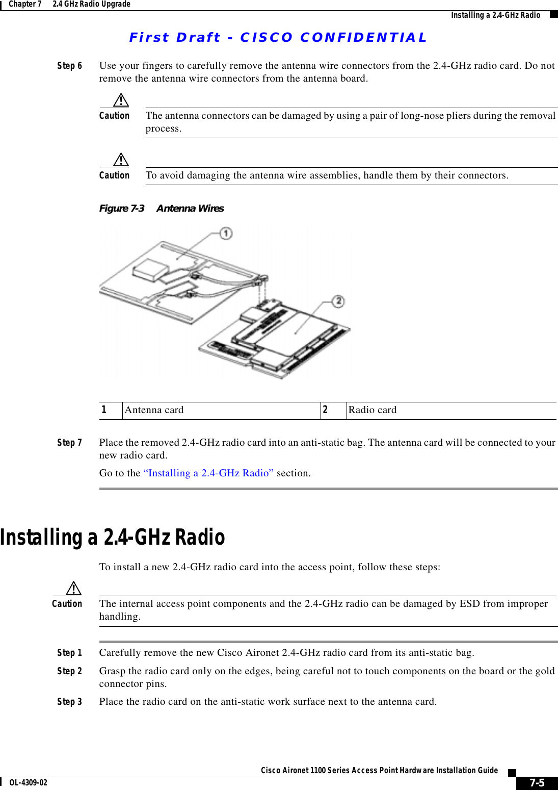
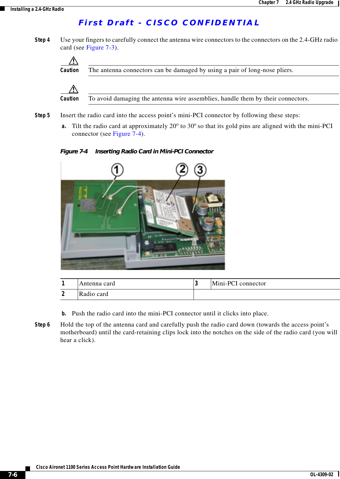
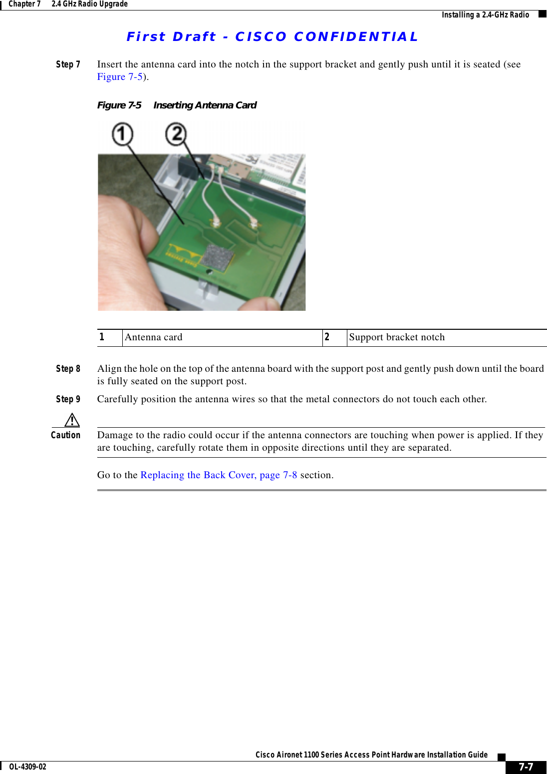
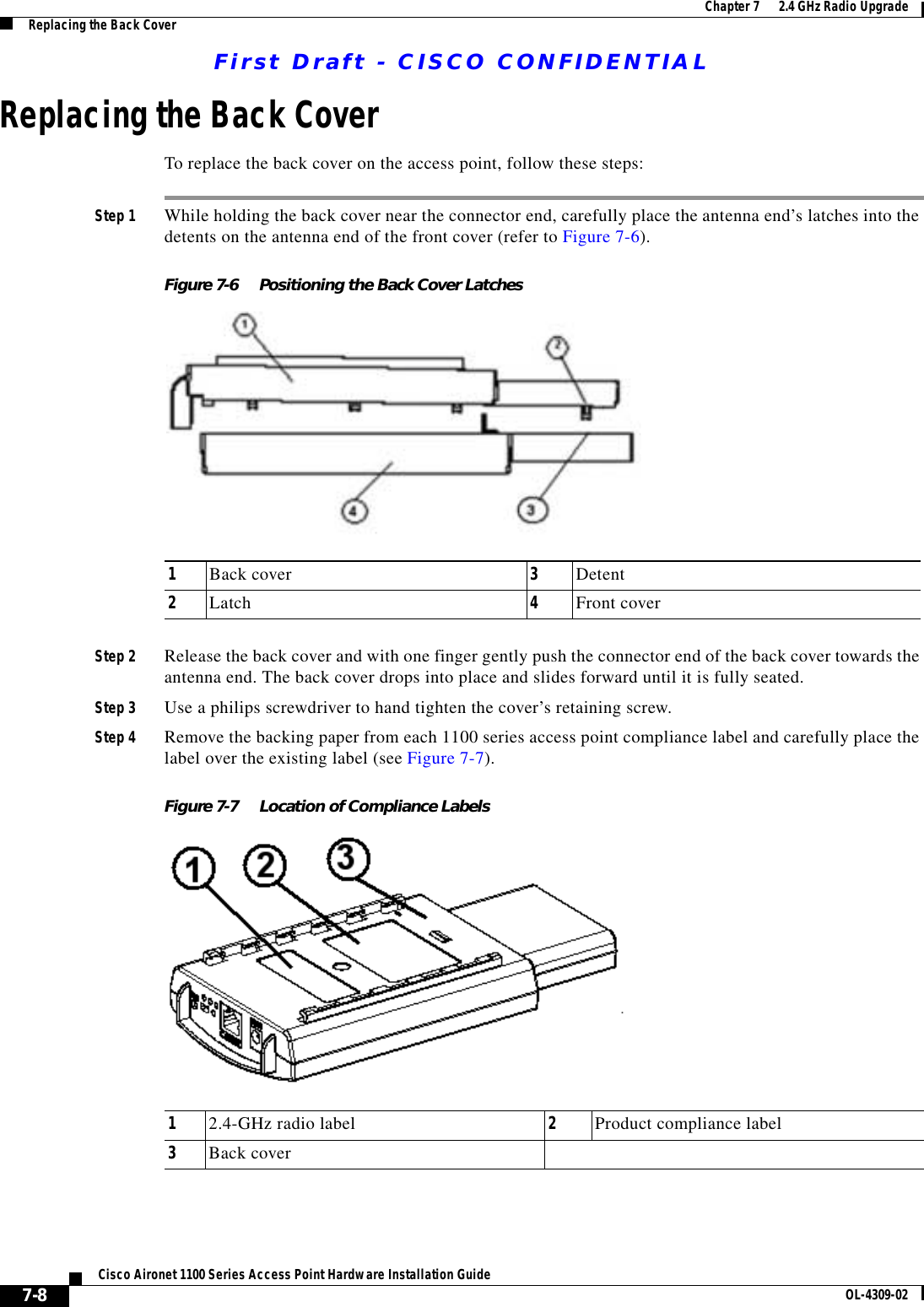
Installation manual
Installation manual
Navigation menu
Upload a User Manual
Namespaces
Wiki Guide
HTML
PDF
Info
Views
User Manual
Discussion / Help
Navigation