Cisco Systems 102048 802.11 b/g Mini-PCI Radio Module User Manual 1100HIG3b
Cisco Systems Inc 802.11 b/g Mini-PCI Radio Module 1100HIG3b
Contents
- 1. User Manual
- 2. Installation manual
Installation manual

CHAPTER
First Draft - CISCO CONFIDENTIAL
7-1
Cisco Aironet 1100 Series Access Point Hardware Installation Guide
OL-4309-02
7
2.4 GHz Radio Upgrade
This chapter provides upgrade instructions for the 2.4-GHz (IEEE 802.11b-compliant or
IEEE 802.11g-compliant) radio card and includes the following sections:
•Upgrade Overview, page 7-2
•Unpacking the Radio, page 7-2
•Removing the Back Cover, page 7-3
•Removing a 2.4-GHz Radio, page 7-4
•Installing a 2.4-GHz Radio, page 7-5
•Replacing the Back Cover, page 7-8
First Draft - CISCO CONFIDENTIAL
7-2
Cisco Aironet 1100 Series Access Point Hardware Installation Guide OL-4309-02
Chapter 7 2.4 GHz Radio Upgrade
Upgrade Overview
Upgrade Overview
This section provides instructions for upgrading the access point 2.4-GHz radio. The following
operations summarize the upgrade procedure:
1. Remove all cables and power connections from the access point.
2. Follow standard electrostatic discharge (ESD) procedures.
3. Place the access point on an ESD-protected work surface.
4. Remove the access point’s back cover.
5. Remove the existing 2.4-GHz radio card.
6. Install the new 2.4-GHz radio card.
7. Replace the access point’s back cover.
8. Install the new compliance labels.
Caution ESD can damage the Cisco Aironet radio and the internal components of the access point. It is
recommended that the 2.4-GHz radio upgrade procedures be performed by an ESD-trained service
technician at an ESD-protected workstation.
Note After you install the new radio, all configurable radio settings will be at default values. Refer to the Cisco
IOS Software Configuration Guide for Cisco Aironet Access Points for complete instructions on
configuring the new radio.
Unpacking the Radio
Each 2.4-GHz (IEEE 802.11G) radio is shipped with the following items:
•Quick start guide
•A product registration card
•A T-10 tamper-resistant Torx L-wrench (not used on 1100 series access points)
•Two 1100 series access point labels
•A 1200 series access point 2.4-GHz radio compliance label (not used on 1100 series access points)
If anything is missing or damaged, contact your Cisco representative for support.
First Draft - CISCO CONFIDENTIAL
7-3
Cisco Aironet 1100 Series Access Point Hardware Installation Guide
OL-4309-02
Chapter 7 2.4 GHz Radio Upgrade Removing the Back Cover
Removing the Back Cover
To remove the access point’s back cover, follow these steps:
Step 1 Remove all cables and power connections from the access point.
Step 2 Remove all static-generating items from the work area, such as plastic material, styrofoam cups, and
other similar items.
Step 3 Place the access point and the new 2.4-GHz radio (in its antistatic bag) on an antistatic work surface.
Step 4 Discharge any static buildup on your body by touching a grounded surface (antistatic work surface)
before proceeding.
Step 5 Position the access point so that the back cover is facing up.
Caution The internal access point components and the 2.4-GHz radio can be damaged by ESD from improper
handling.
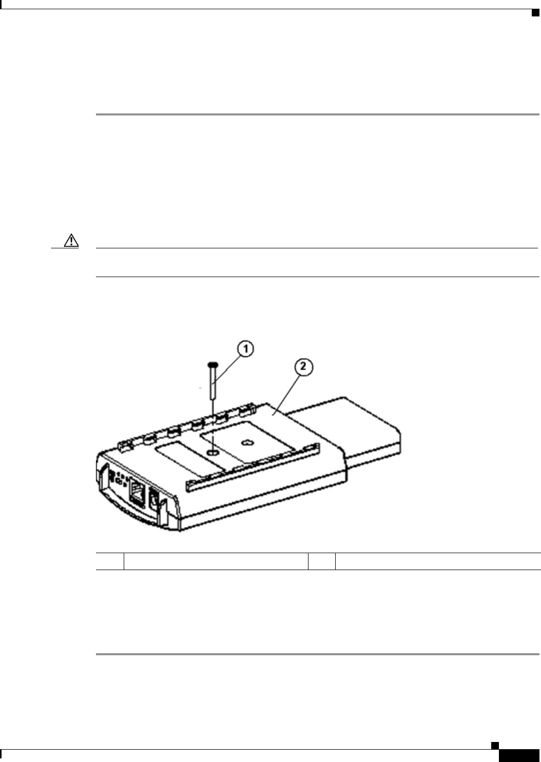
Step 6 Remove the back cover retaining screw using a philips screwdriver (see Figure 7-1).
Figure 7-1 Access Point Back Cover Screw
Step 7 Hold the front cover with one hand and with the other hand gently slide the back cover towards the
connector end of the unit.
Step 8 Gently lift the connector end of the back cover and remove the cover.
Go to the “Removing a 2.4-GHz Radio” section.
1Back cover screw 2Back cover
First Draft - CISCO CONFIDENTIAL
7-4
Cisco Aironet 1100 Series Access Point Hardware Installation Guide OL-4309-02
Chapter 7 2.4 GHz Radio Upgrade
Removing a 2.4-GHz Radio
Removing a 2.4-GHz Radio
To remove a 2.4-GHz radio card from your access point, follow these steps:
Caution The internal access point components and the 2.4-GHz radio can be damaged by ESD from improper
handling.
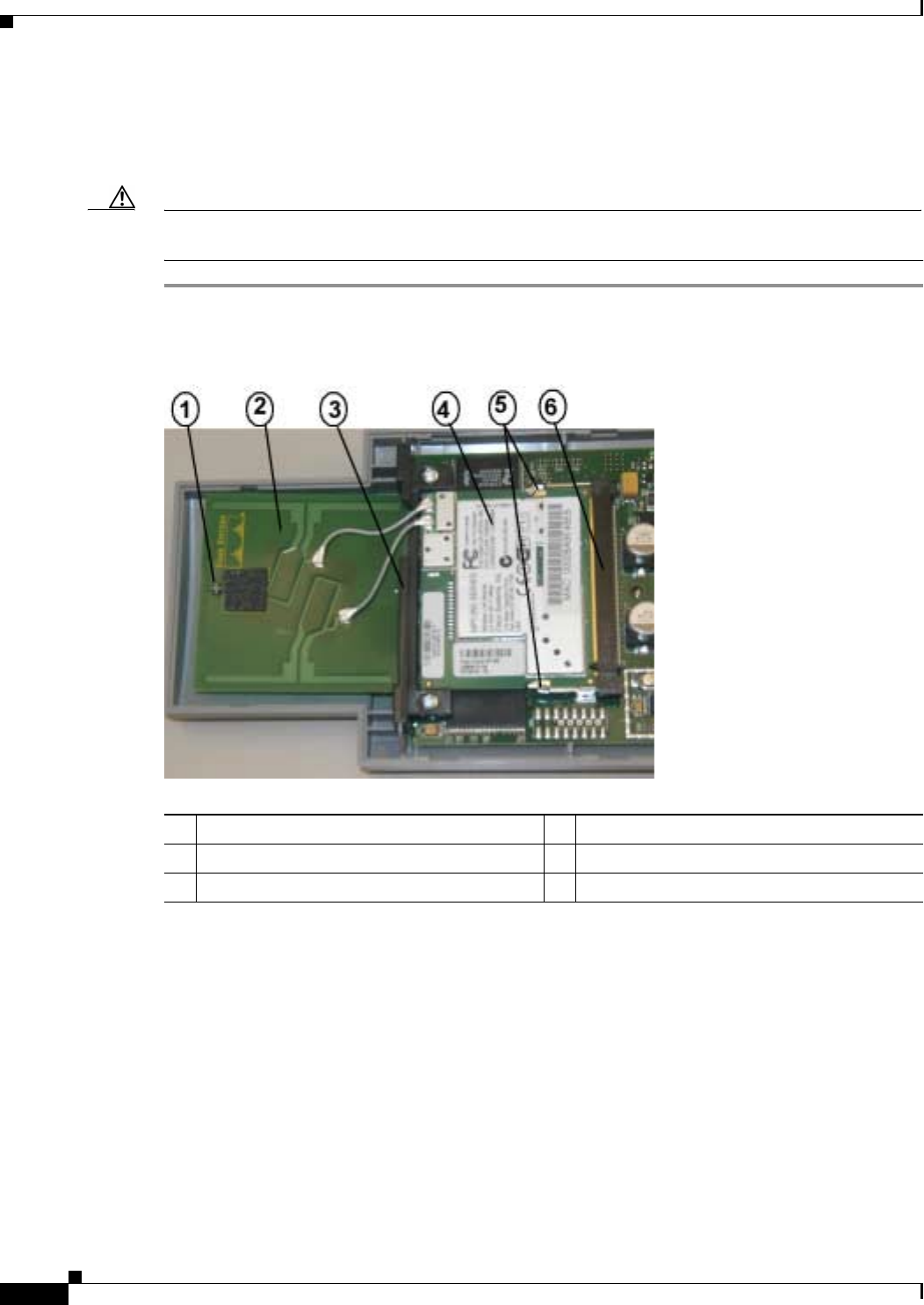
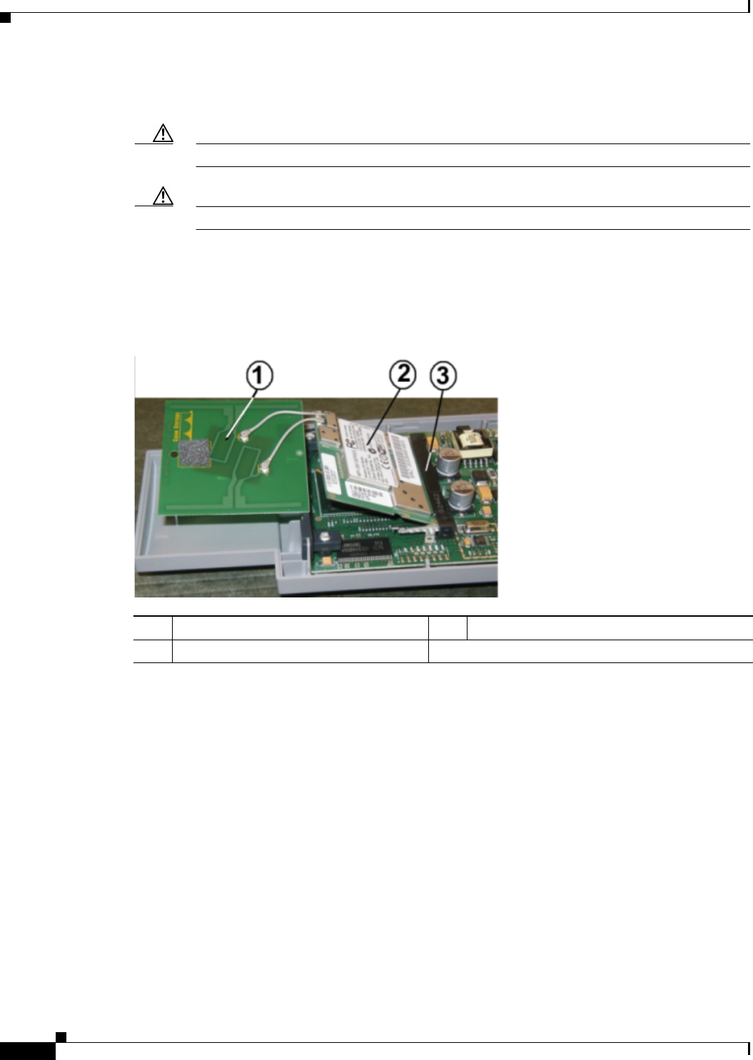
Step 1 Gently lift the top of the antenna card until it clears the plus shaped (+) support post (see Figure 7-2).
Figure 7-2 Radio Card and Antenna Card
Step 2 Gently pull the antenna card to remove it from the notch in the support bracket. Do not disconnect the
antenna wire connectors.
Step 3 Push the card-retaining clips (on each side of card) away from the radio card (see Figure 7-2). When
released, the radio card springs up. Do not disconnect the antenna wires.
Step 4 Remove the 2.4-GHz radio card from the mini-PCI connector by performing the following operations:
a. Grasp the radio card only on the edges, being careful not to touch components on the board or the
gold connector pins.
b. Remove the 2.4-GHz card from the mini-PCI connector.
Step 5 Place the radio card and antenna card on the ESD-protected work surface.
1Support post 4Radio Card
2Antenna card 5Card-retaining clips
3Support bracket 6Mini-PCI connector
First Draft - CISCO CONFIDENTIAL
7-5
Cisco Aironet 1100 Series Access Point Hardware Installation Guide
OL-4309-02
Chapter 7 2.4 GHz Radio Upgrade Installing a 2.4-GHz Radio
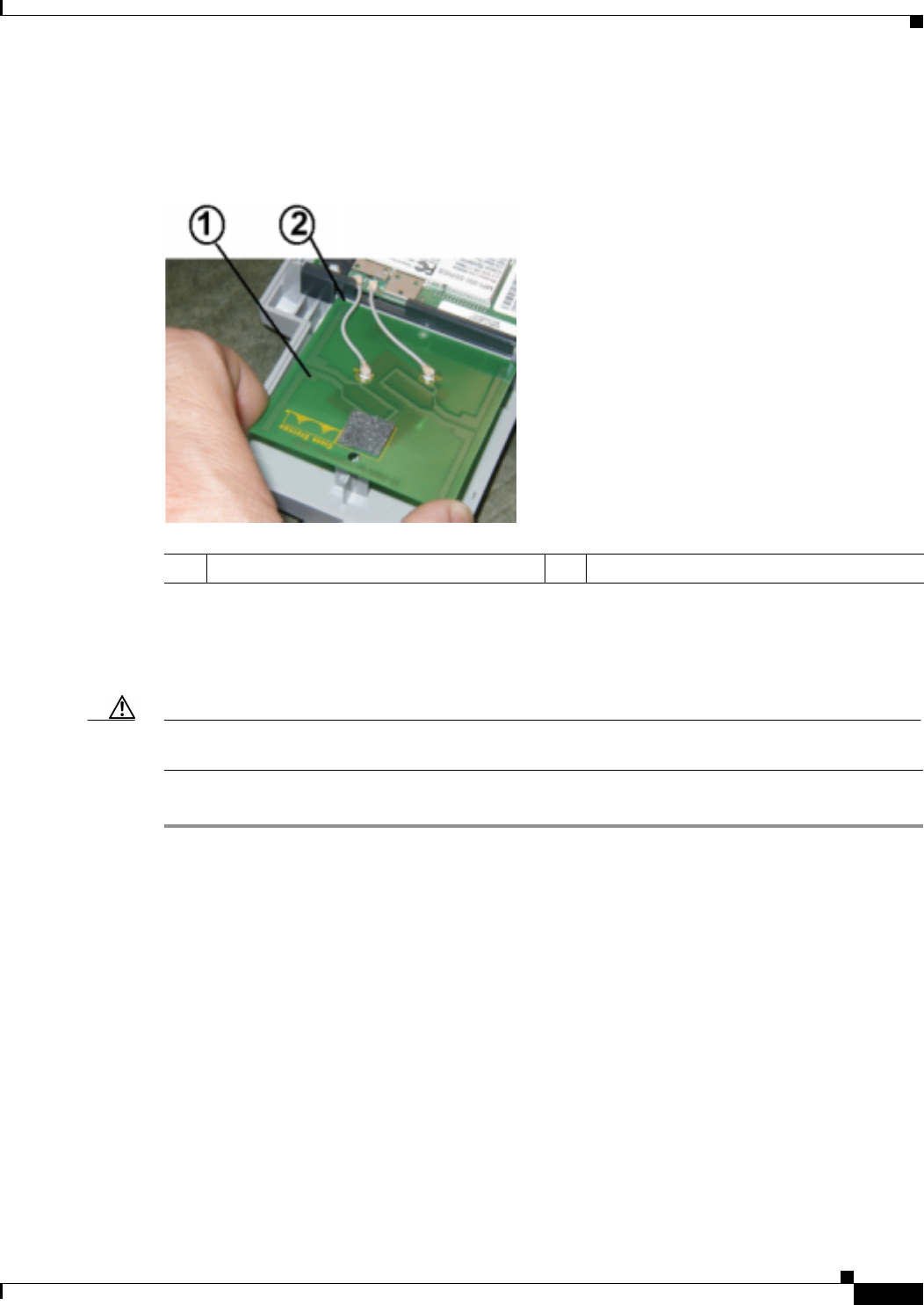
Step 6 Use your fingers to carefully remove the antenna wire connectors from the 2.4-GHz radio card. Do not
remove the antenna wire connectors from the antenna board.
Caution The antenna connectors can be damaged by using a pair of long-nose pliers during the removal
process.
Caution To avoid damaging the antenna wire assemblies, handle them by their connectors.
Figure 7-3 Antenna Wires
Step 7 Place the removed 2.4-GHz radio card into an anti-static bag. The antenna card will be connected to your
new radio card.
Go to the “Installing a 2.4-GHz Radio” section.
Installing a 2.4-GHz Radio
To install a new 2.4-GHz radio card into the access point, follow these steps:
Caution The internal access point components and the 2.4-GHz radio can be damaged by ESD from improper
handling.
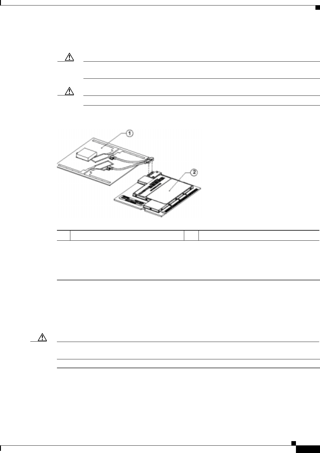
Step 1 Carefully remove the new Cisco Aironet 2.4-GHz radio card from its anti-static bag.
Step 2 Grasp the radio card only on the edges, being careful not to touch components on the board or the gold
connector pins.
Step 3 Place the radio card on the anti-static work surface next to the antenna card.
1Antenna card 2Radio card
First Draft - CISCO CONFIDENTIAL
7-6
Cisco Aironet 1100 Series Access Point Hardware Installation Guide OL-4309-02
Chapter 7 2.4 GHz Radio Upgrade
Installing a 2.4-GHz Radio
Step 4 Use your fingers to carefully connect the antenna wire connectors to the connectors on the 2.4-GHz radio
card (see Figure 7-3).
Caution The antenna connectors can be damaged by using a pair of long-nose pliers.
Caution To avoid damaging the antenna wire assemblies, handle them by their connectors.
Step 5 Insert the radio card into the access point’s mini-PCI connector by following these steps:
a. Tilt the radio card at approximately 20o to 30o so that its gold pins are aligned with the mini-PCI
connector (see Figure 7-4).
Figure 7-4 Inserting Radio Card in Mini-PCI Connector
b. Push the radio card into the mini-PCI connector until it clicks into place.
Step 6 Hold the top of the antenna card and carefully push the radio card down (towards the access point’s
motherboard) until the card-retaining clips lock into the notches on the side of the radio card (you will
hear a click).
1Antenna card 3Mini-PCI connector
2Radio card
First Draft - CISCO CONFIDENTIAL
7-7
Cisco Aironet 1100 Series Access Point Hardware Installation Guide
OL-4309-02
Chapter 7 2.4 GHz Radio Upgrade Installing a 2.4-GHz Radio
Step 7 Insert the antenna card into the notch in the support bracket and gently push until it is seated (see
Figure 7-5).
Figure 7-5 Inserting Antenna Card
Step 8 Align the hole on the top of the antenna board with the support post and gently push down until the board
is fully seated on the support post.
Step 9 Carefully position the antenna wires so that the metal connectors do not touch each other.
Caution Damage to the radio could occur if the antenna connectors are touching when power is applied. If they
are touching, carefully rotate them in opposite directions until they are separated.
Go to the Replacing the Back Cover, page 7-8 section.
1Antenna card 2Support bracket notch
First Draft - CISCO CONFIDENTIAL
7-8
Cisco Aironet 1100 Series Access Point Hardware Installation Guide OL-4309-02
Chapter 7 2.4 GHz Radio Upgrade
Replacing the Back Cover
Replacing the Back Cover
To replace the back cover on the access point, follow these steps:
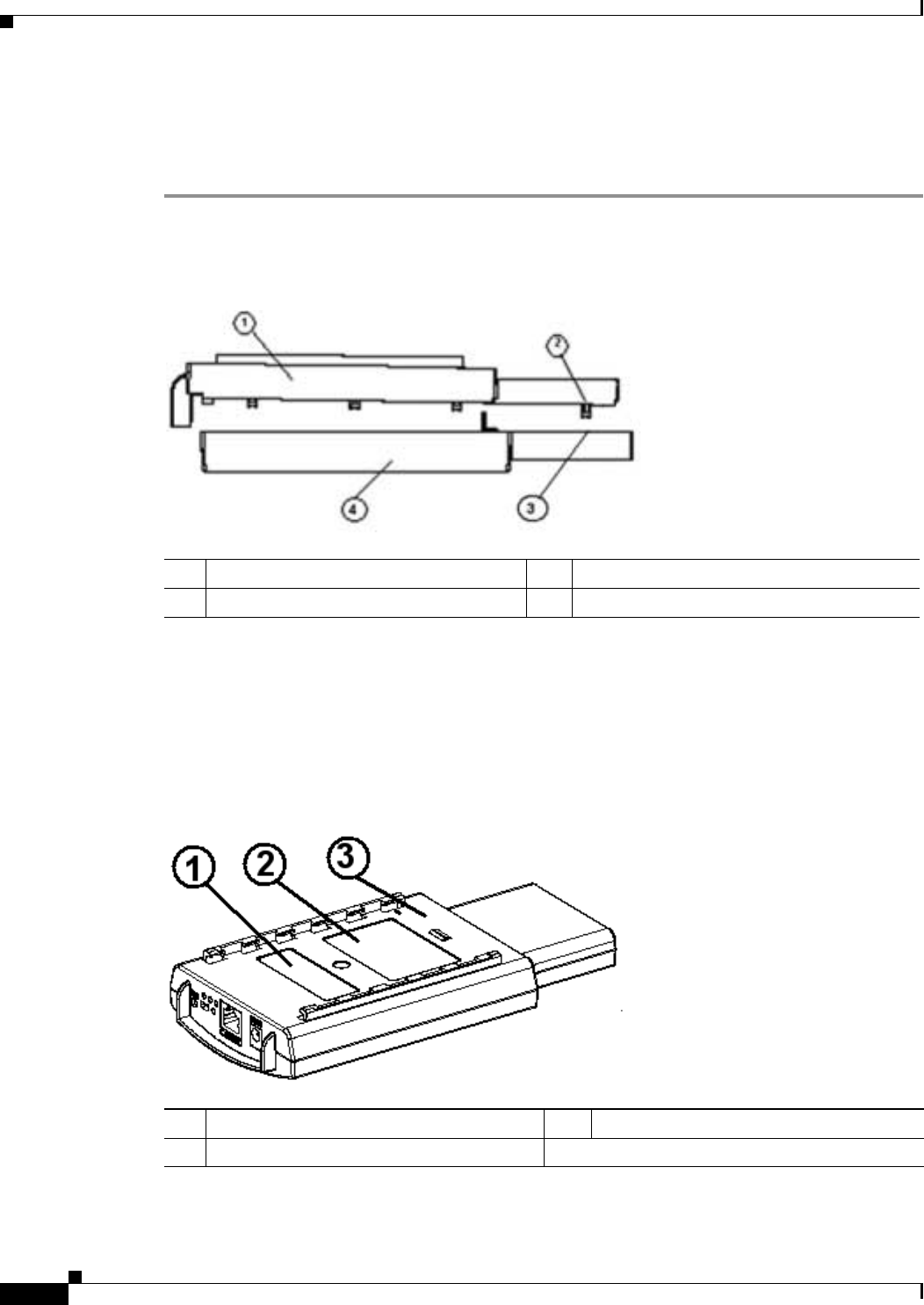
Step 1 While holding the back cover near the connector end, carefully place the antenna end’s latches into the
detents on the antenna end of the front cover (refer to Figure 7-6).
Figure 7-6 Positioning the Back Cover Latches
Step 2 Release the back cover and with one finger gently push the connector end of the back cover towards the
antenna end. The back cover drops into place and slides forward until it is fully seated.
Step 3 Use a philips screwdriver to hand tighten the cover’s retaining screw.
Step 4 Remove the backing paper from each 1100 series access point compliance label and carefully place the
label over the existing label (see Figure 7-7).
Figure 7-7 Location of Compliance Labels
1Back cover 3Detent
2Latch 4Front cover
12.4-GHz radio label 2Product compliance label
3Back cover

First Draft - CISCO CONFIDENTIAL
7-9
Cisco Aironet 1100 Series Access Point Hardware Installation Guide
OL-4309-02
Chapter 7 2.4 GHz Radio Upgrade Replacing the Back Cover
The radio card installation is now complete. To configure the new radio with your new wireless network
settings, refer to the Cisco IOS Software Configuration Guide for Cisco Aironet Access Points.