Cisco Systems 102050 802.11 a/g Cardbus Adapter User Manual AIR XX21AG HIG
Cisco Systems Inc 802.11 a/g Cardbus Adapter AIR XX21AG HIG
UserManual.wiki
>
Cisco Systems
>
102050 User Manual
>
User Manual 2
Contents
1.
User Manual 1
2.
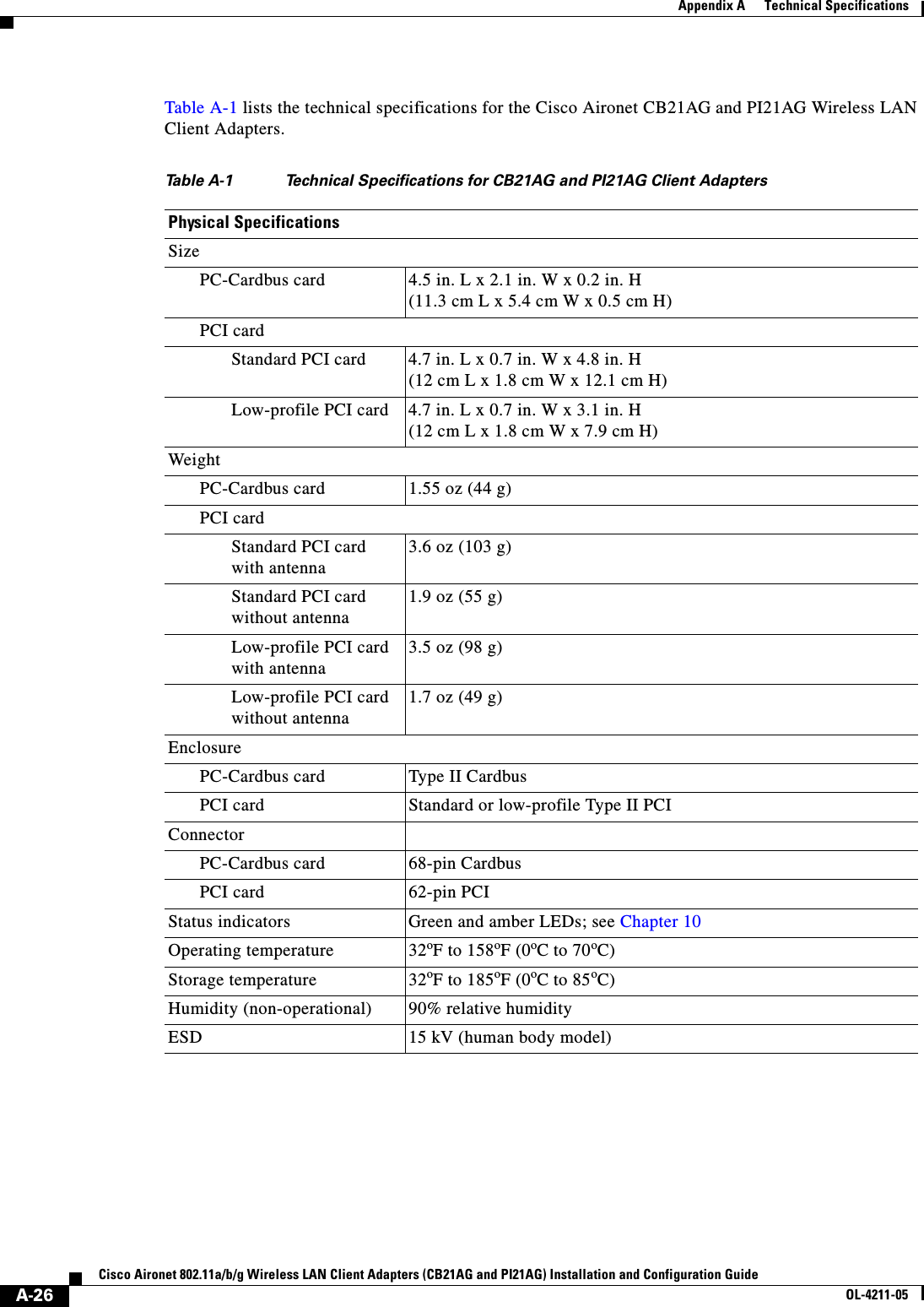
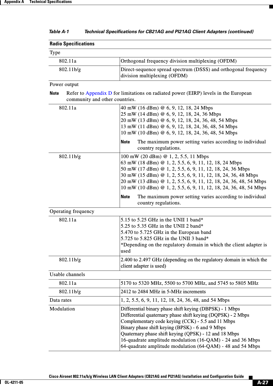
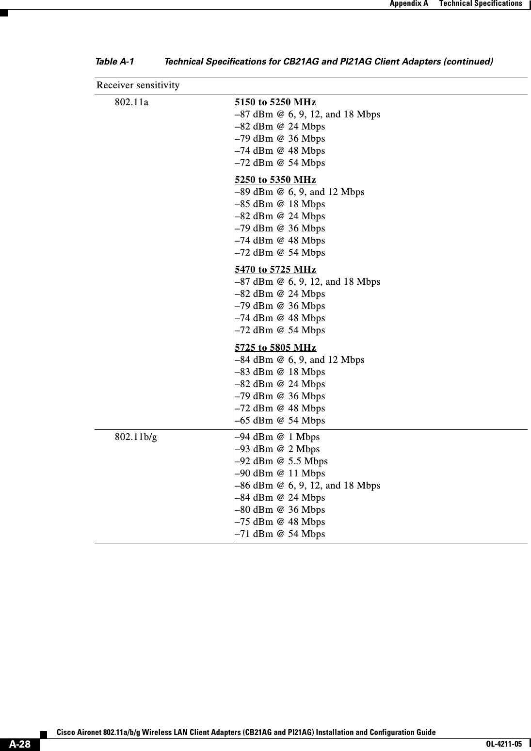
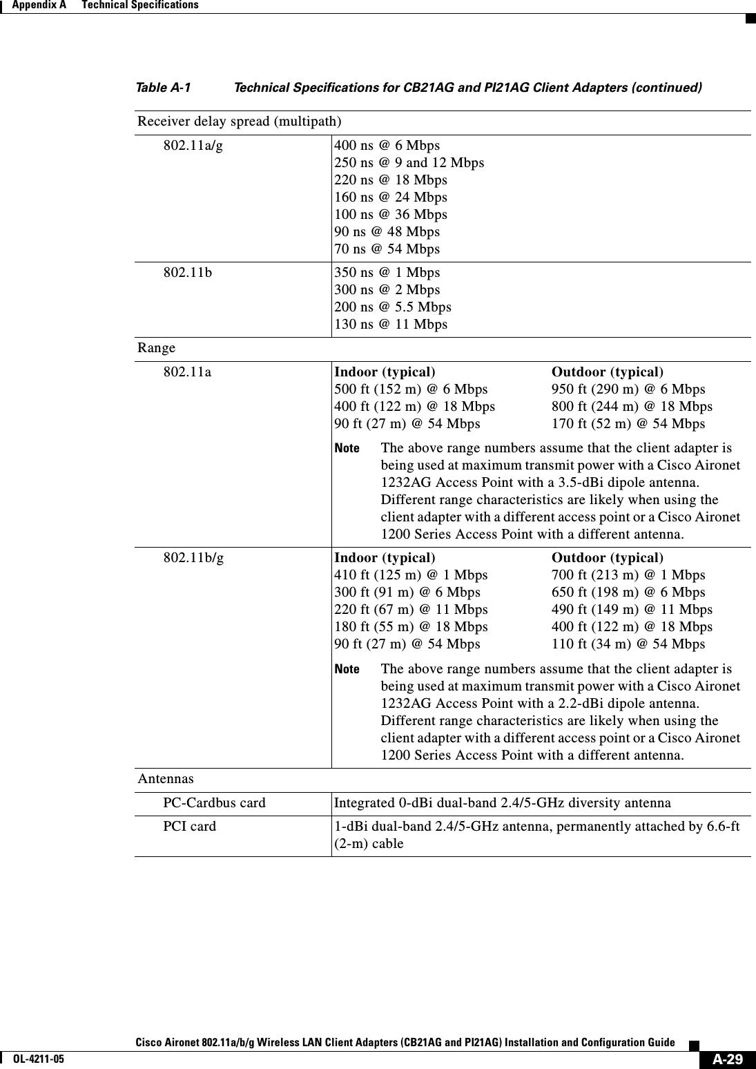
User Manual 2
User Manual 2
Navigation menu
Upload a User Manual
Namespaces
Wiki Guide
HTML
PDF
Info
Views
User Manual
Discussion / Help
Navigation