Cisco Systems 102057 Air-AP1000 Series Dual Band 2.4/5 GHz Access Point User Manual Product Guide SANS
Cisco Systems Inc Air-AP1000 Series Dual Band 2.4/5 GHz Access Point Product Guide SANS
UserManual.wiki
>
Cisco Systems
>
102057 User Manual
User Manual
Navigation menu
Upload a User Manual
Namespaces
Wiki Guide
HTML
PDF
Info
Views
User Manual
Discussion / Help
Navigation


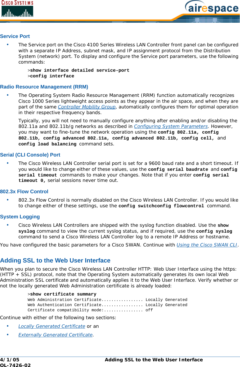
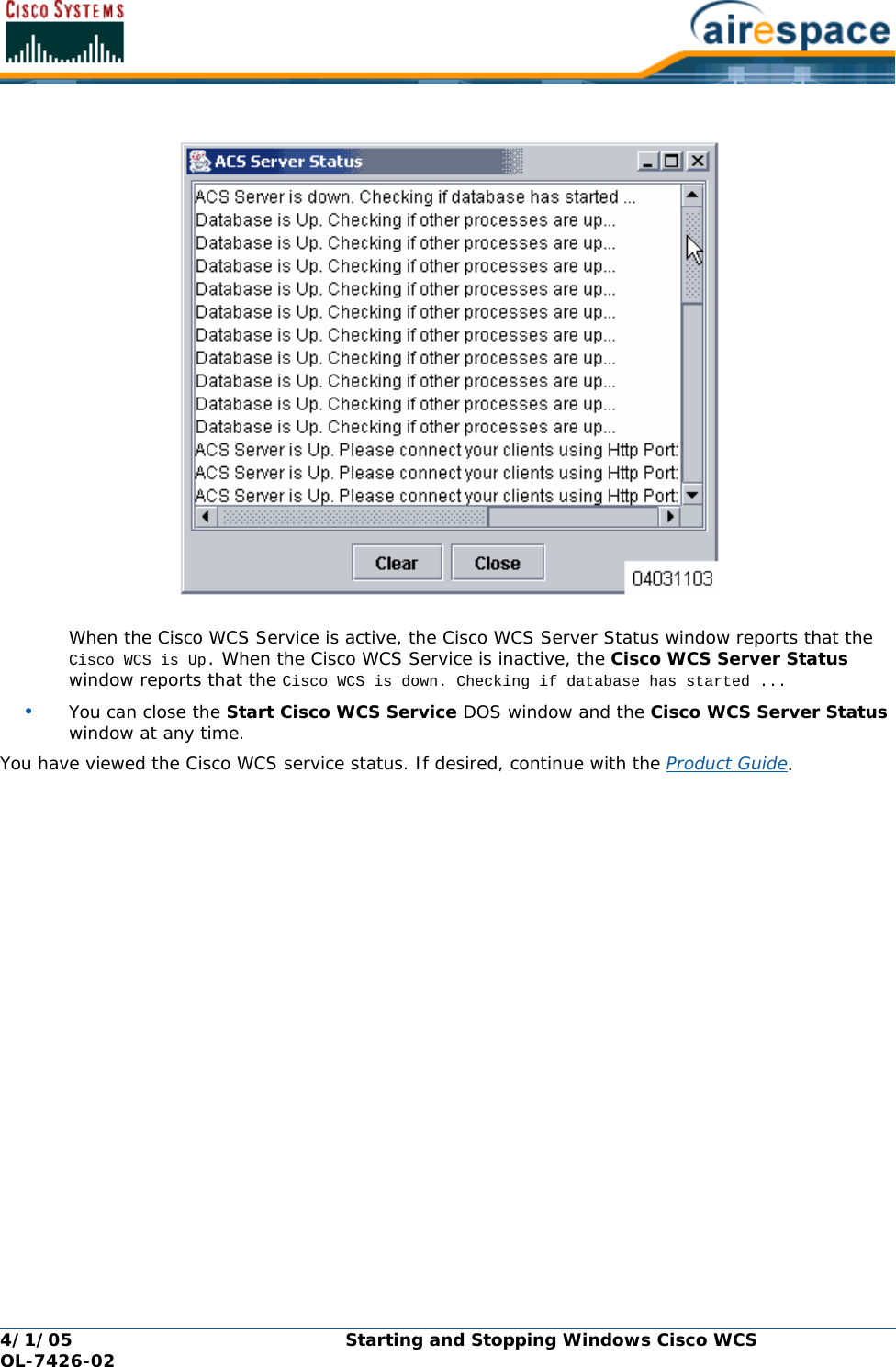
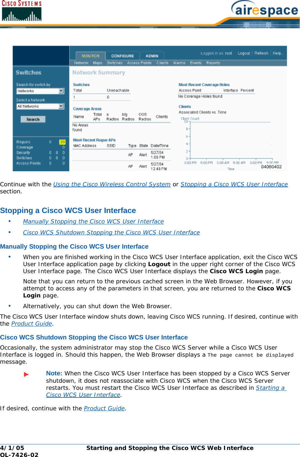
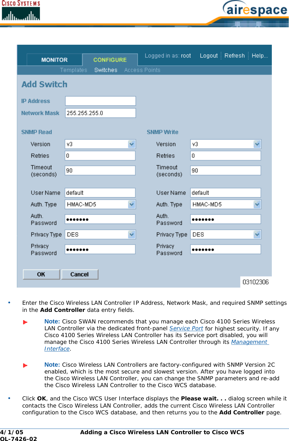
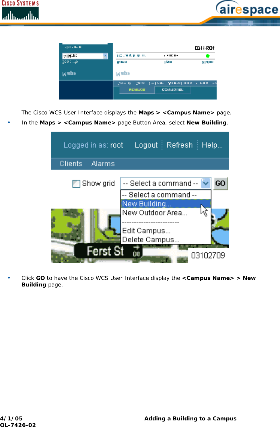
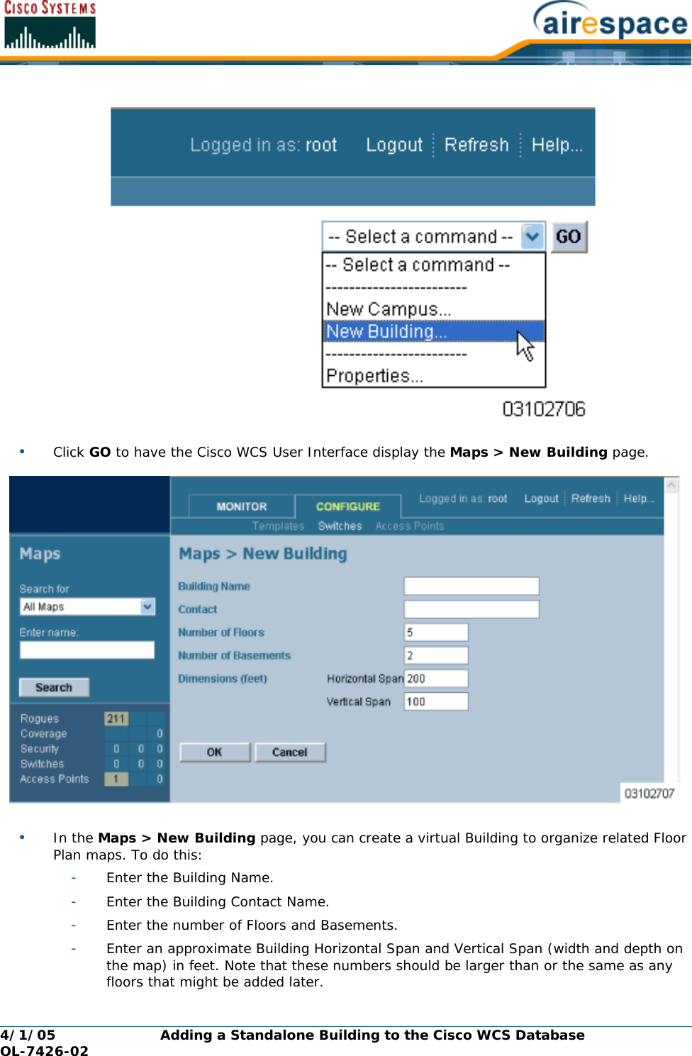
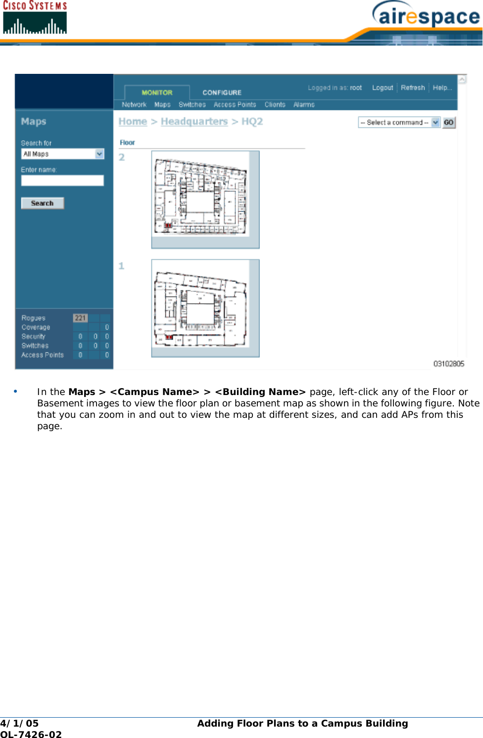
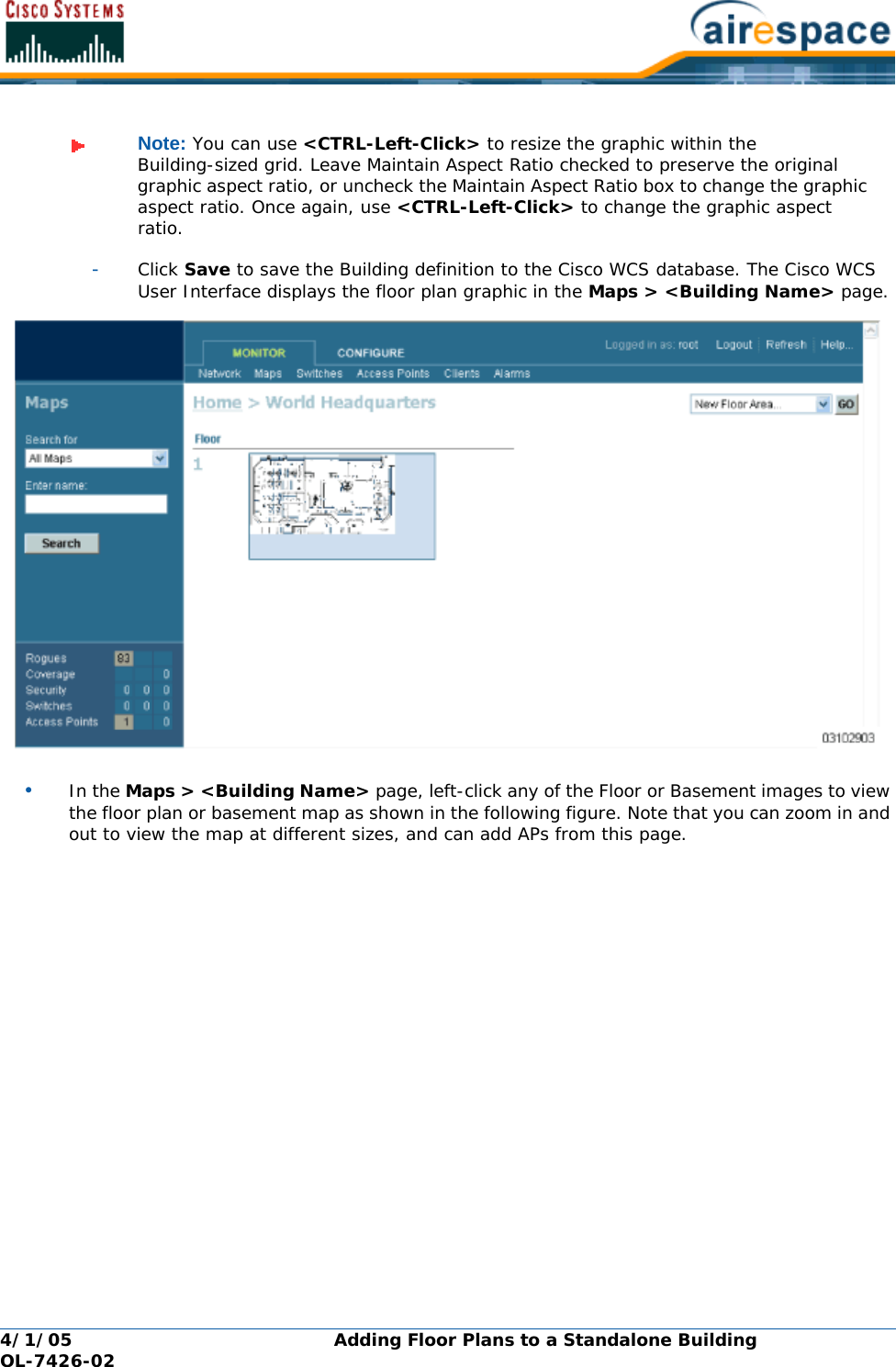
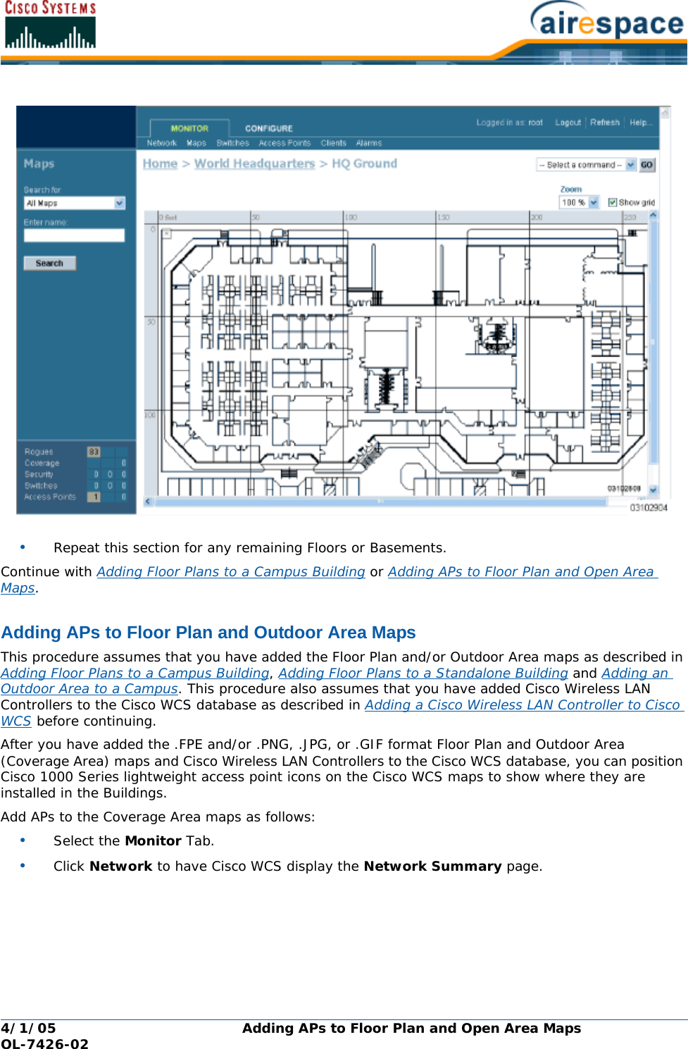
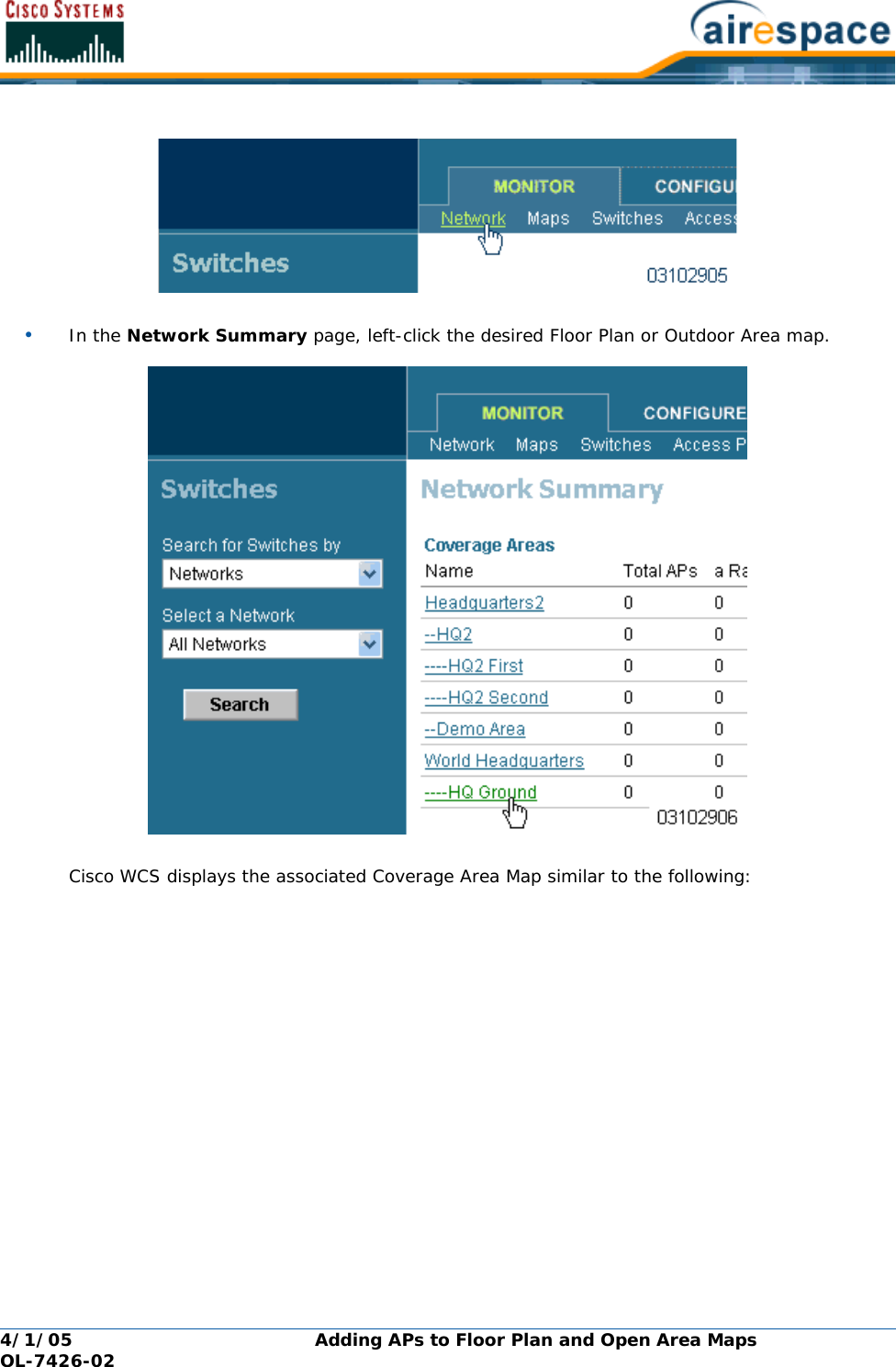
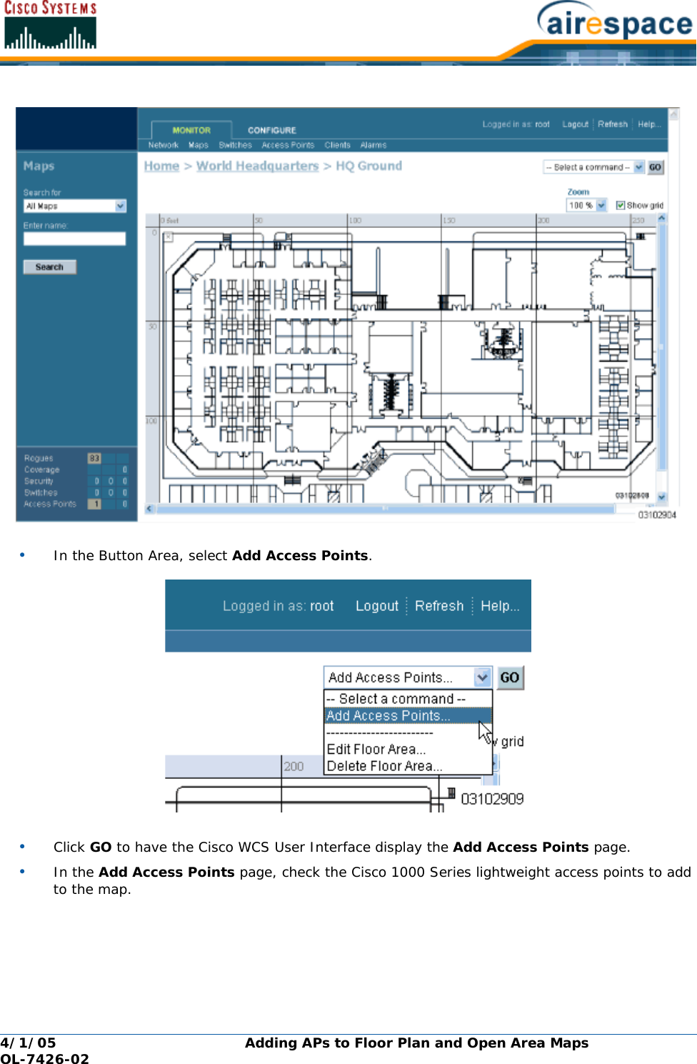
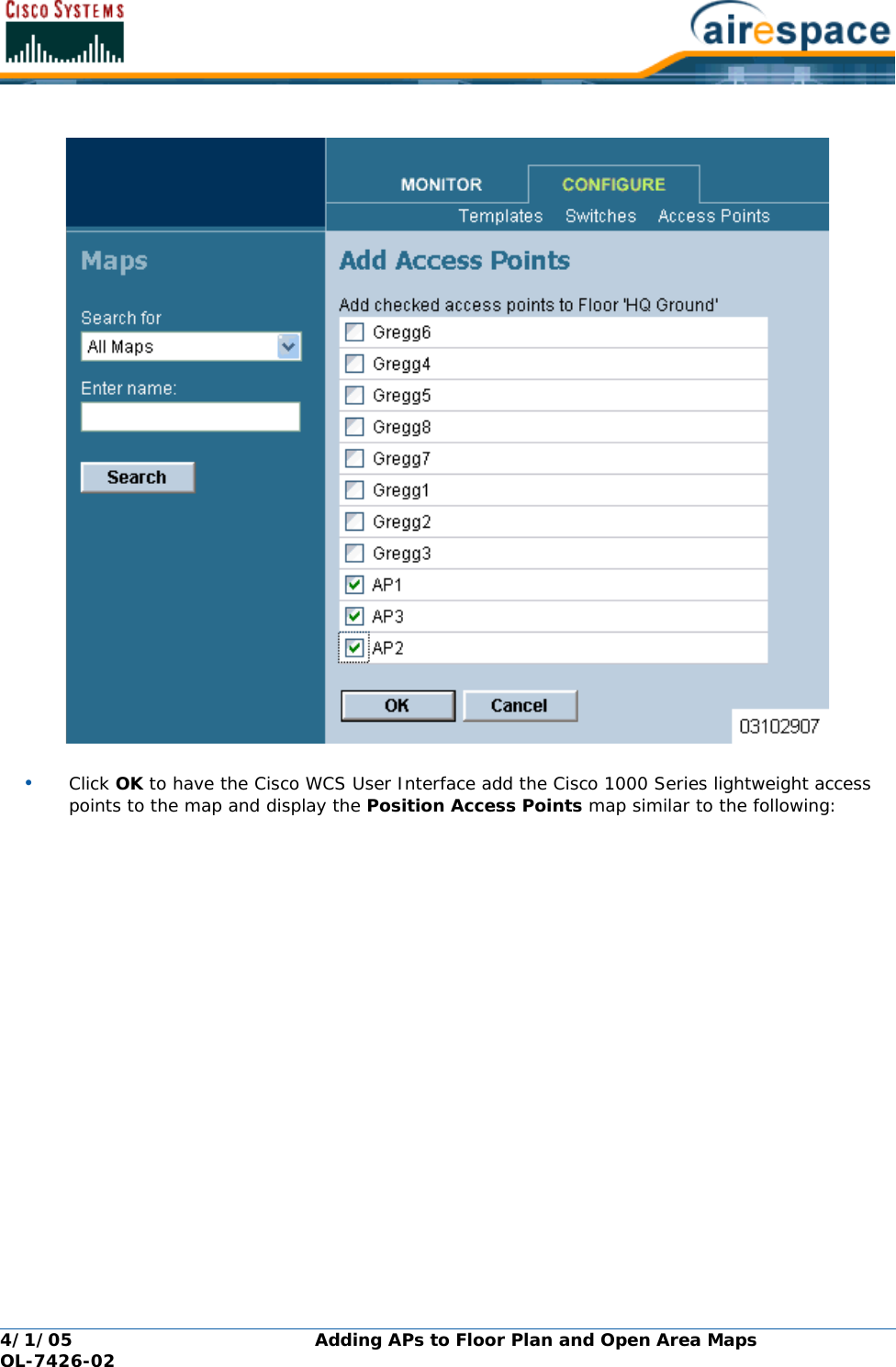
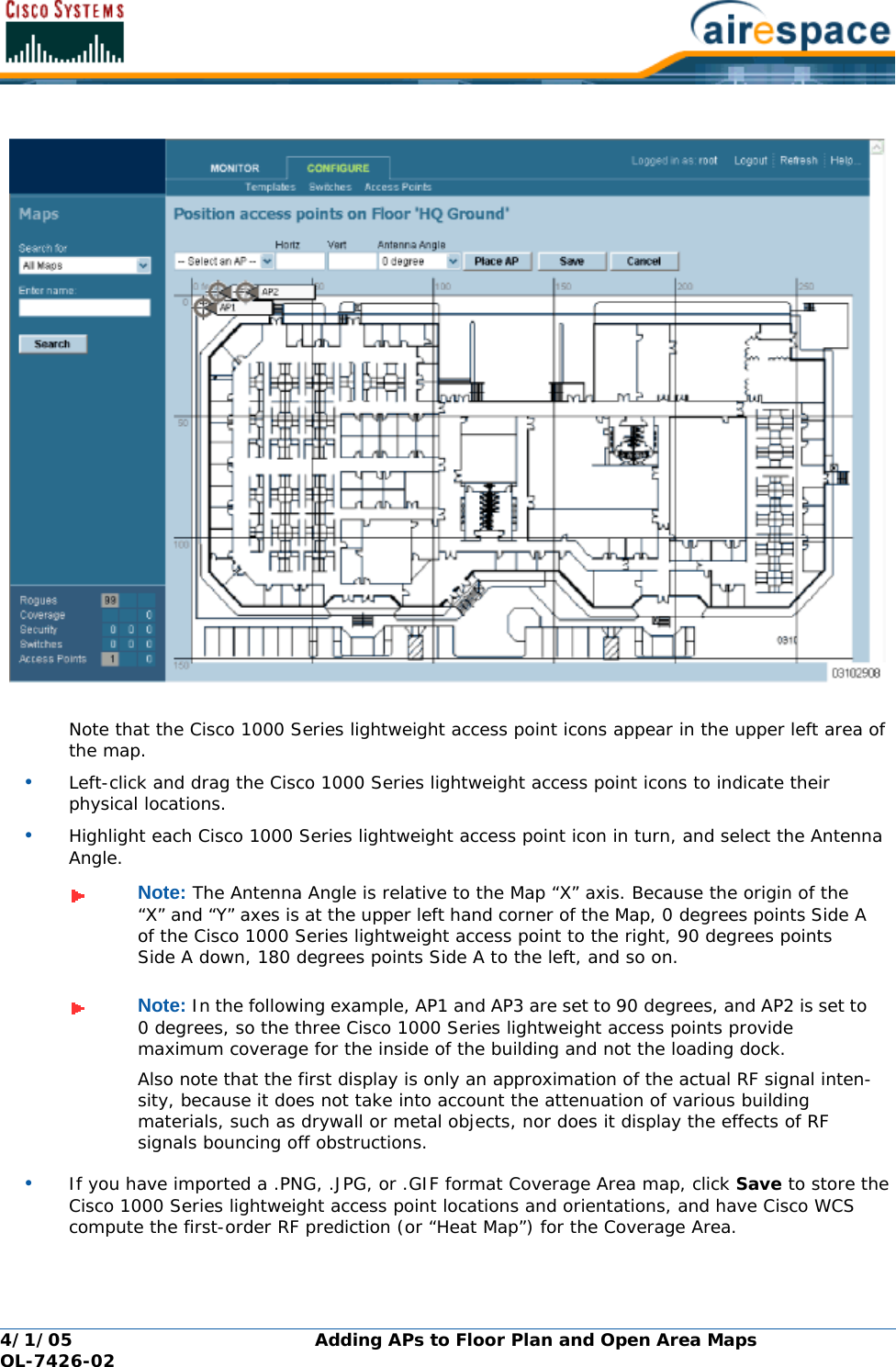
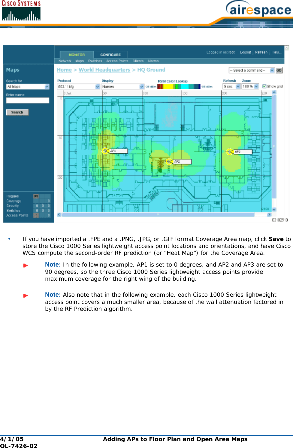
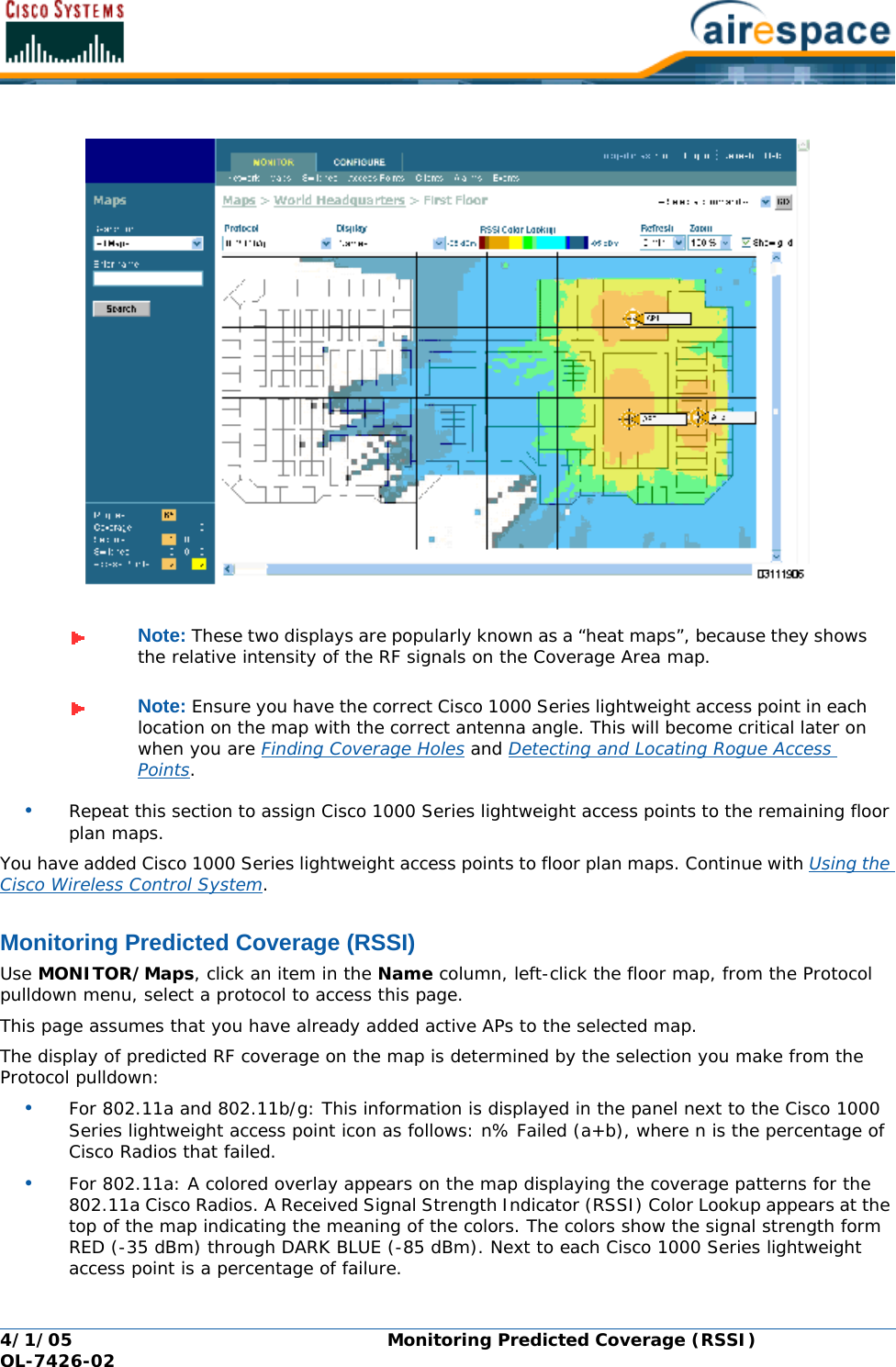
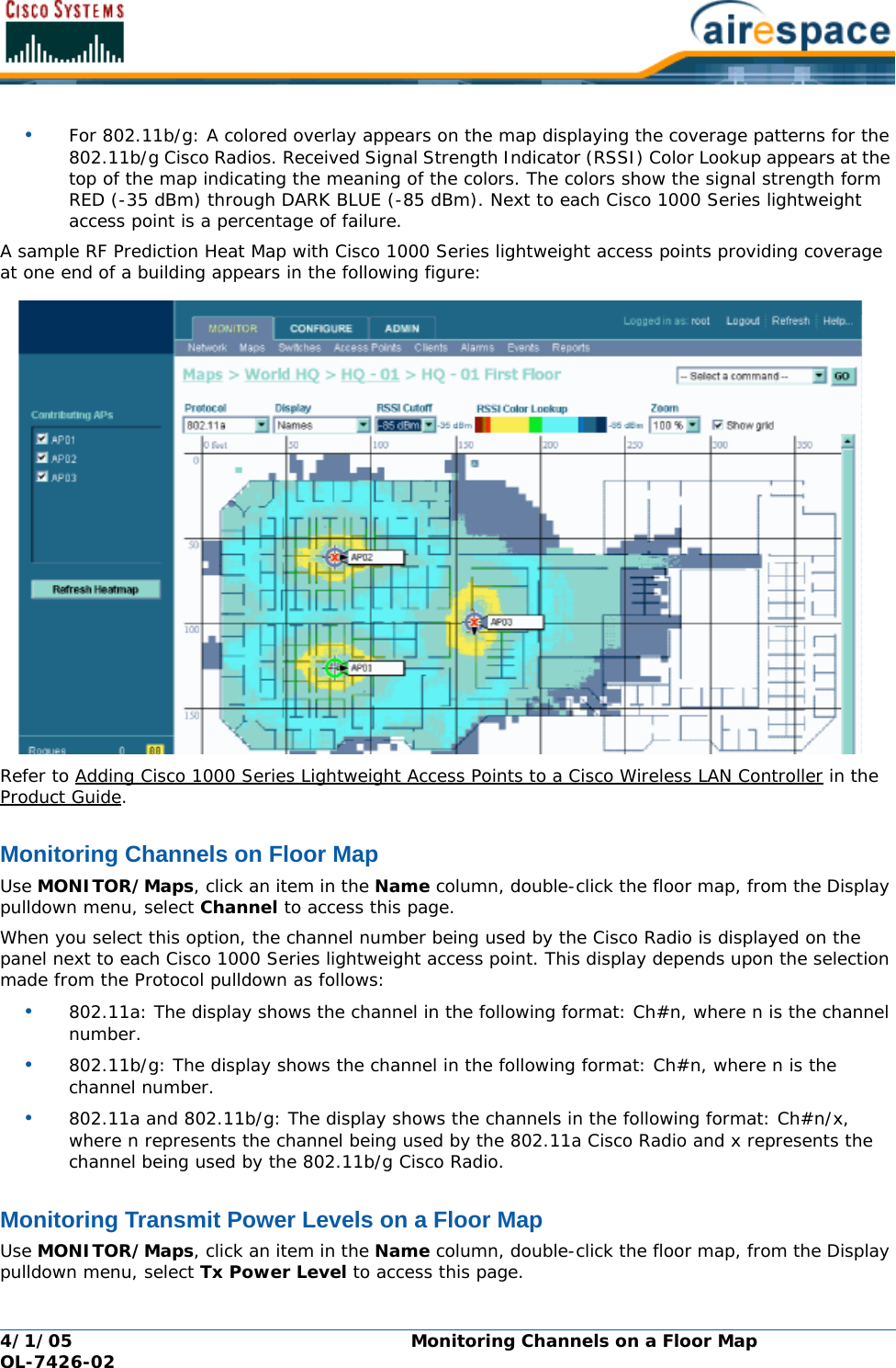
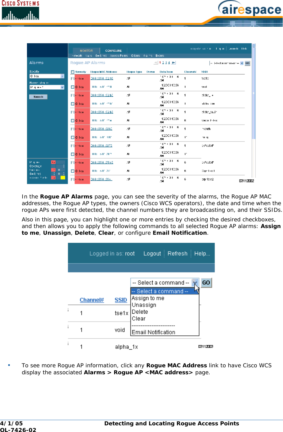
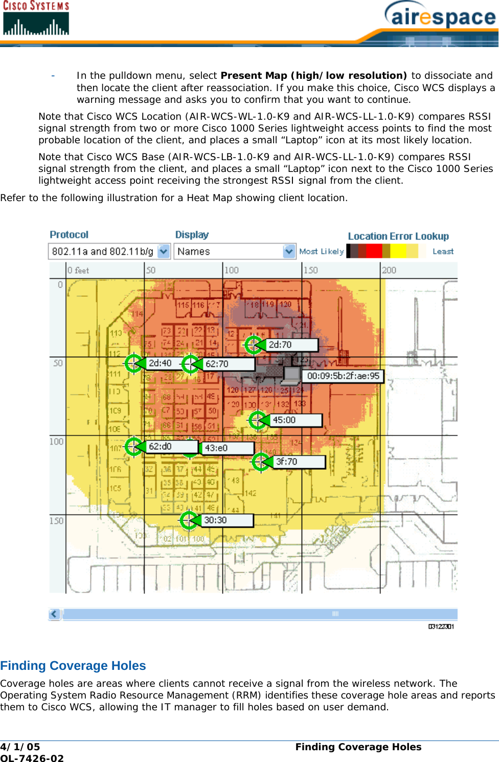
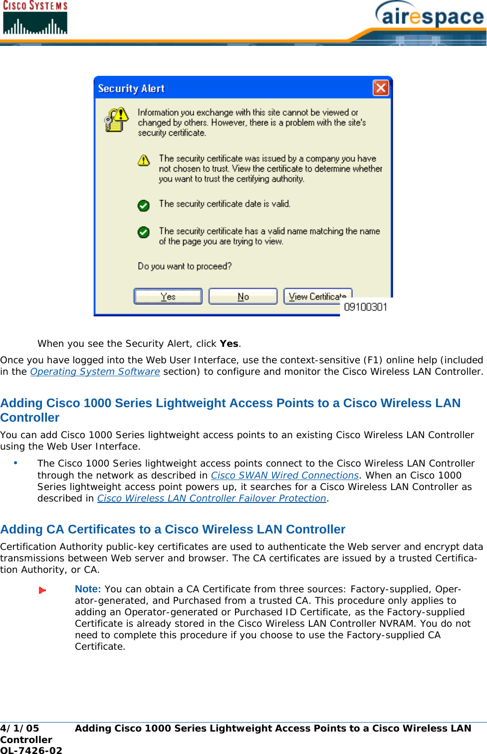
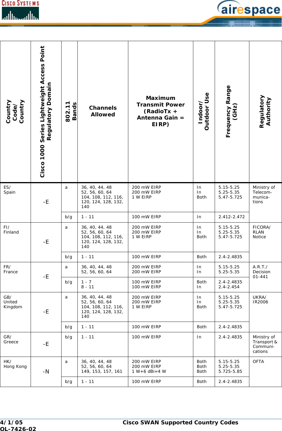
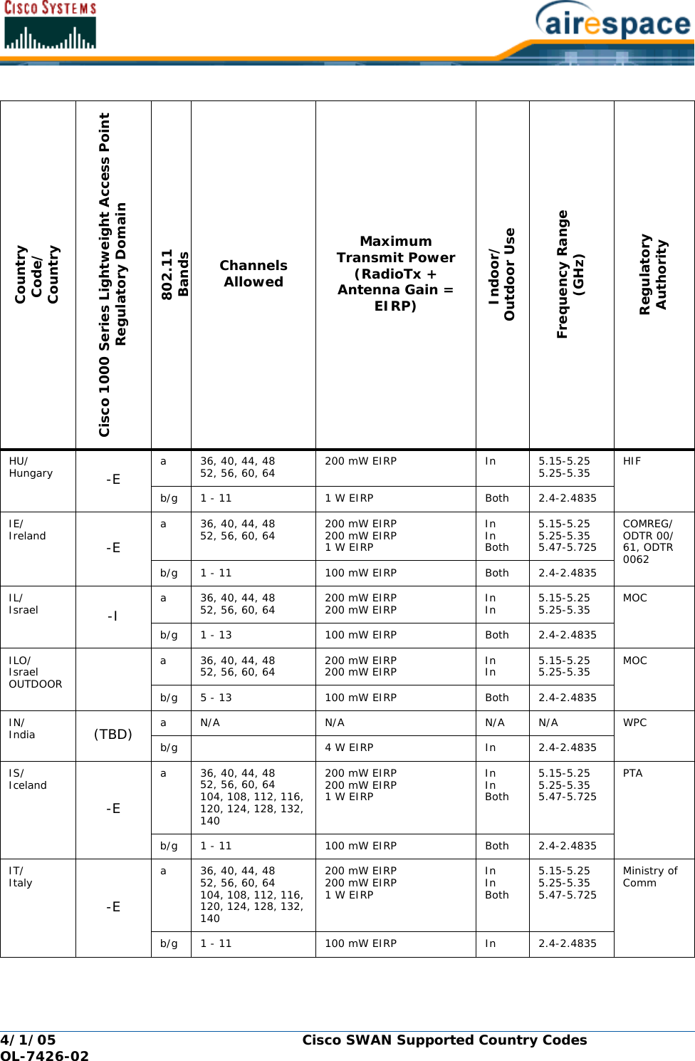
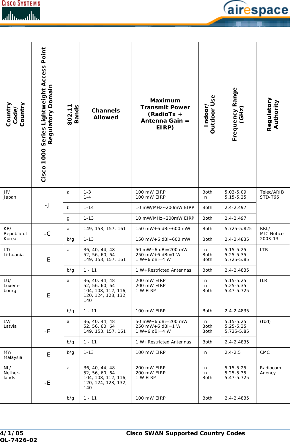
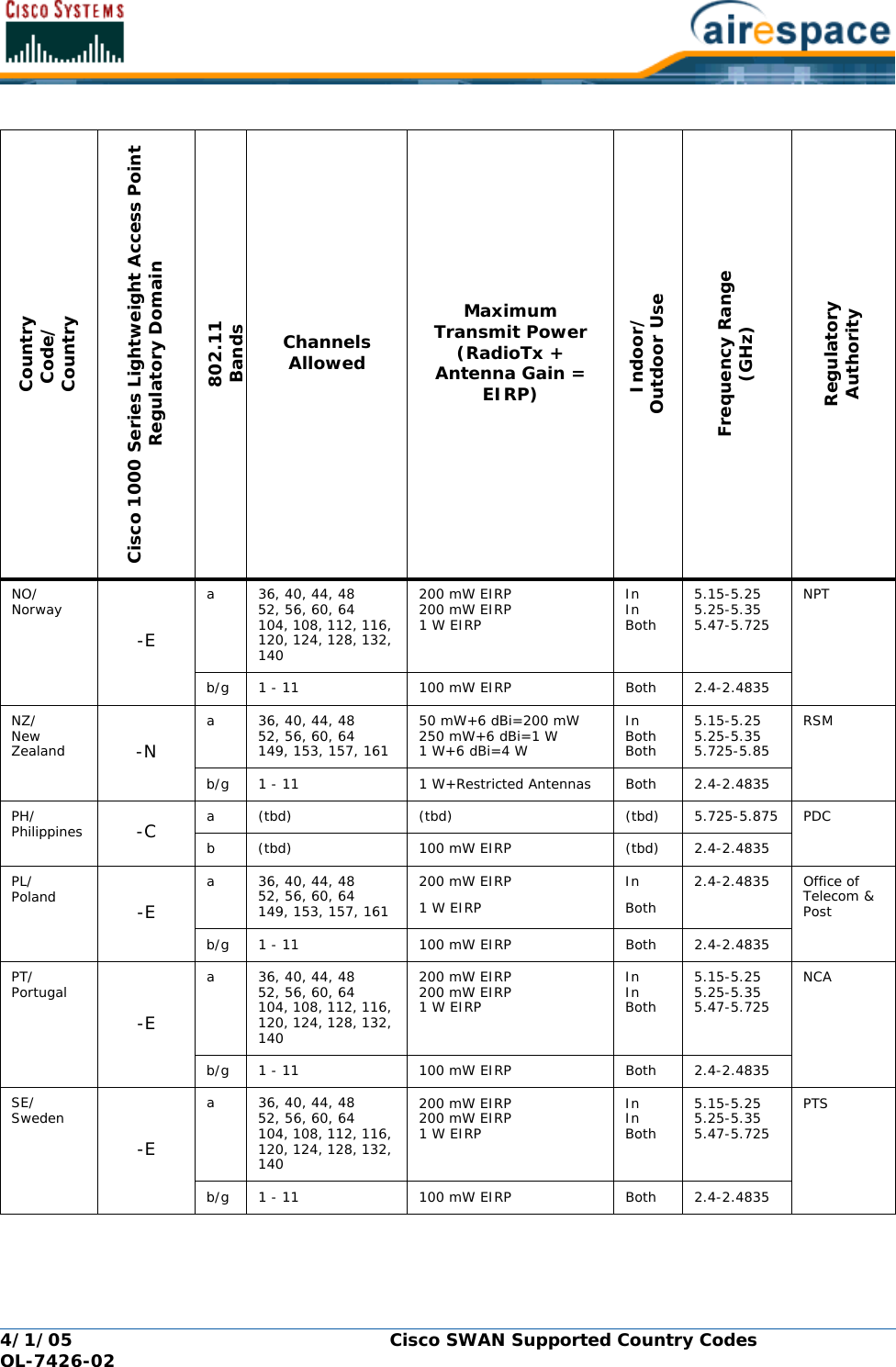
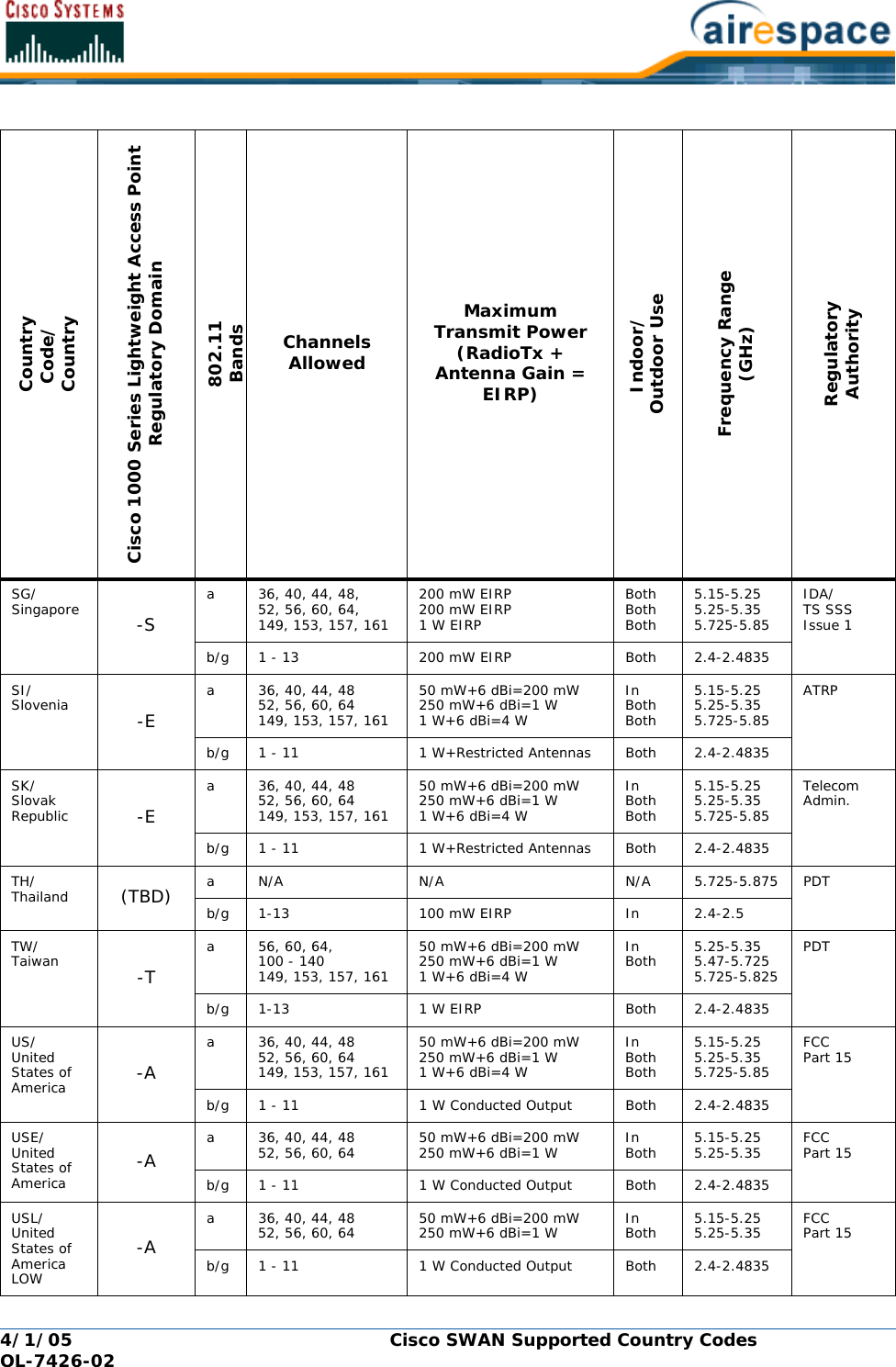
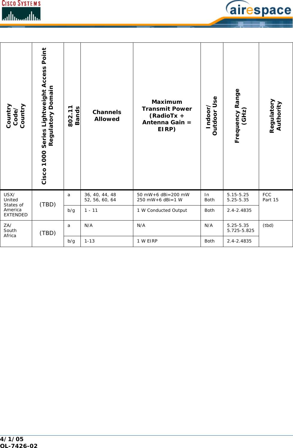
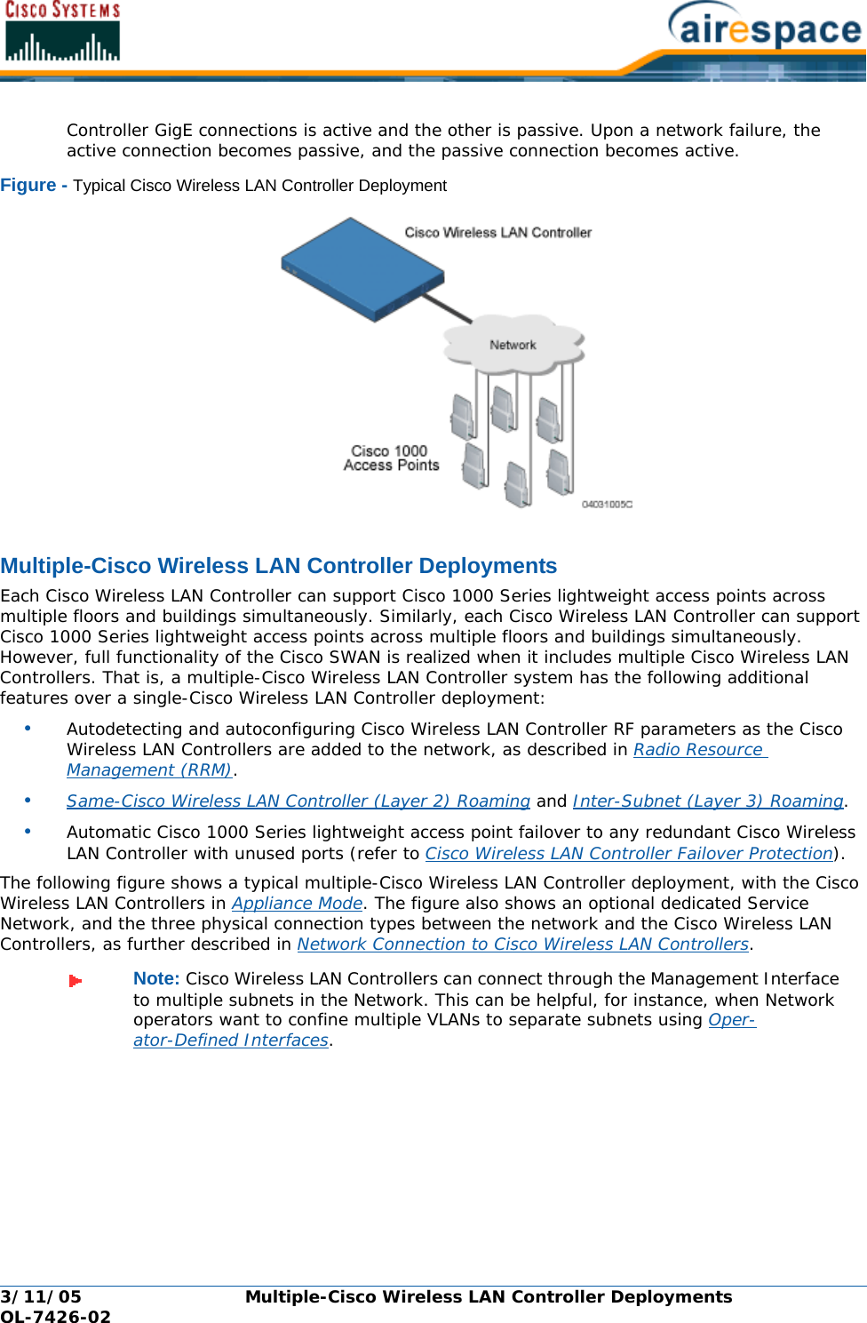
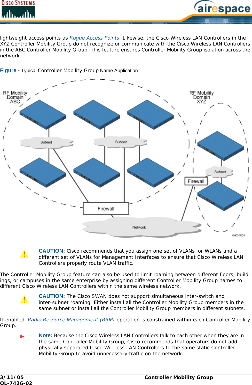
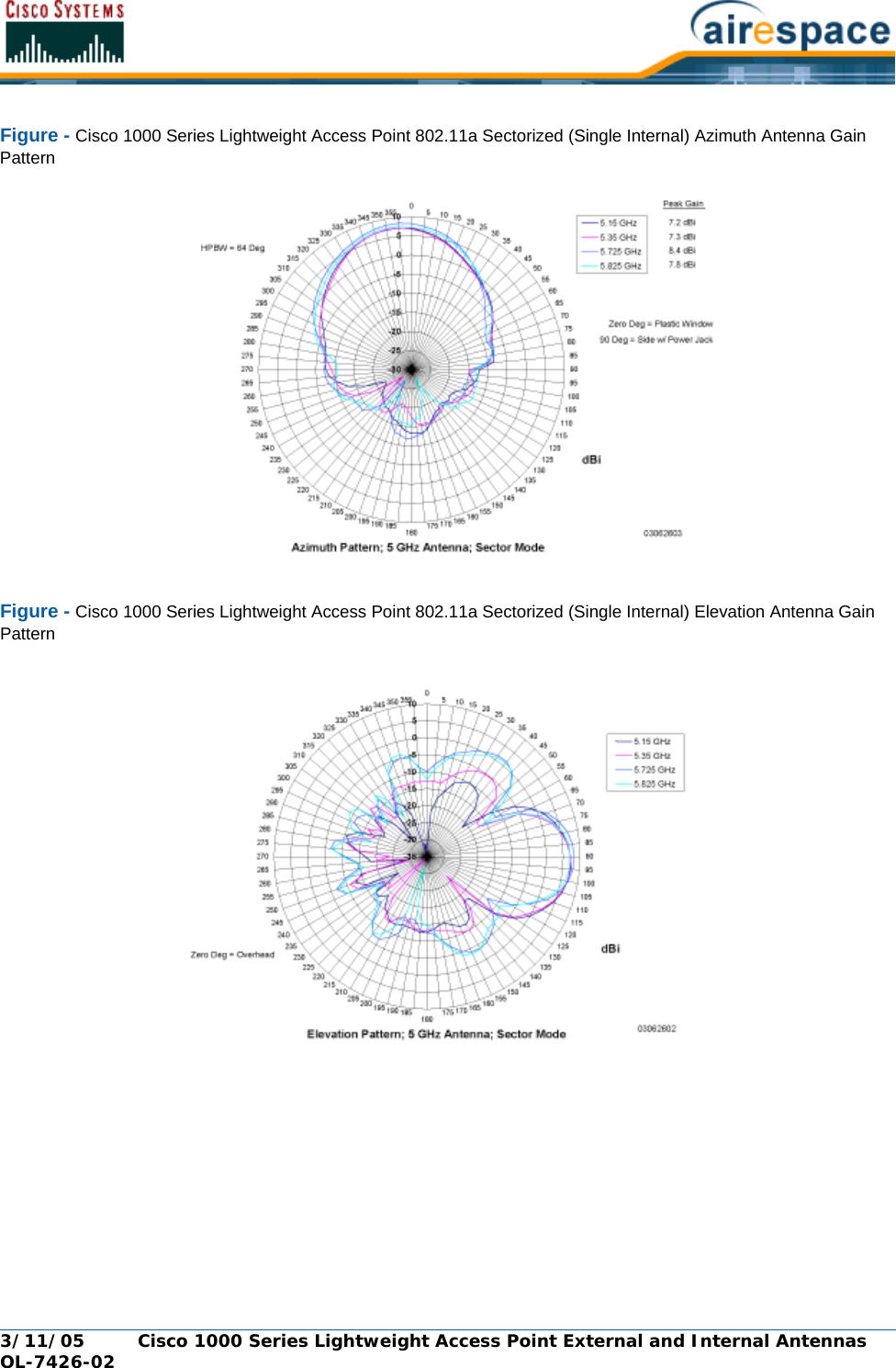
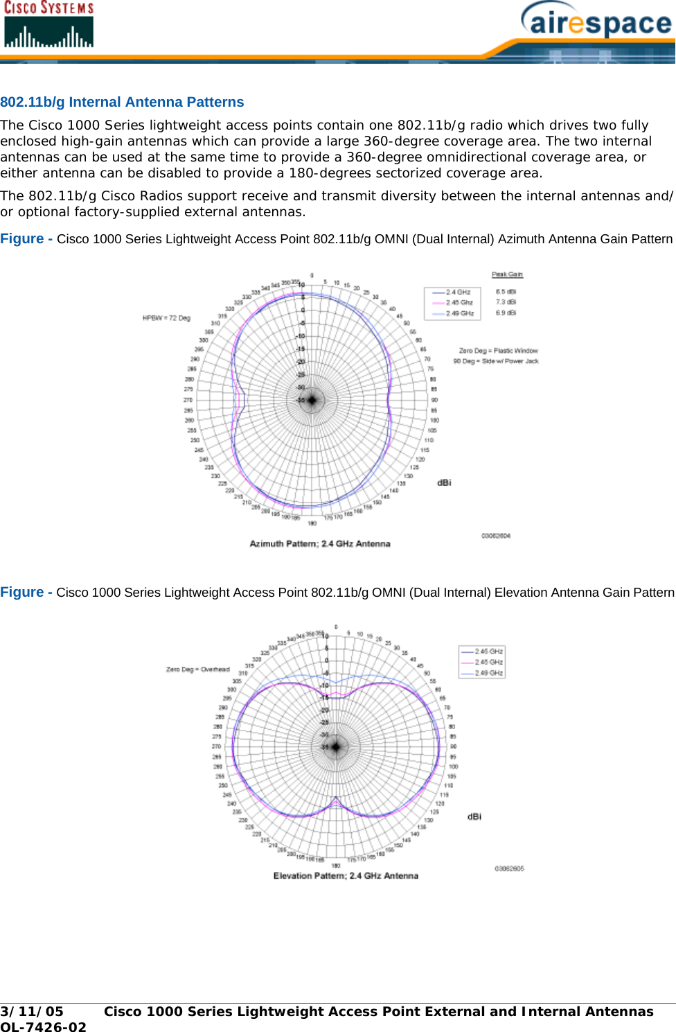
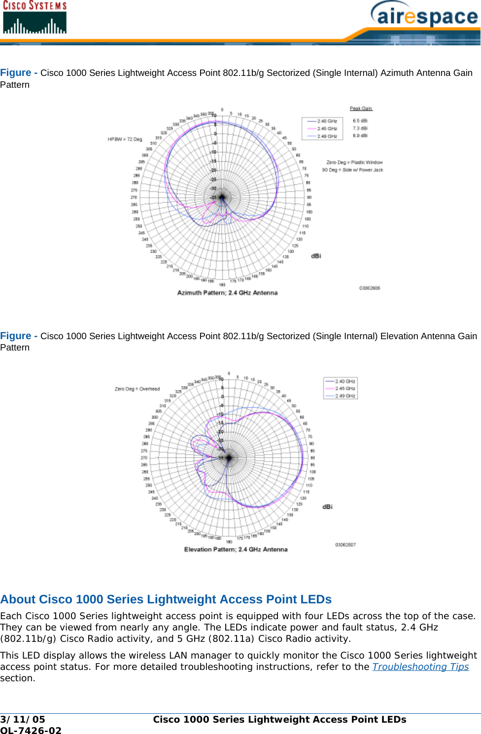
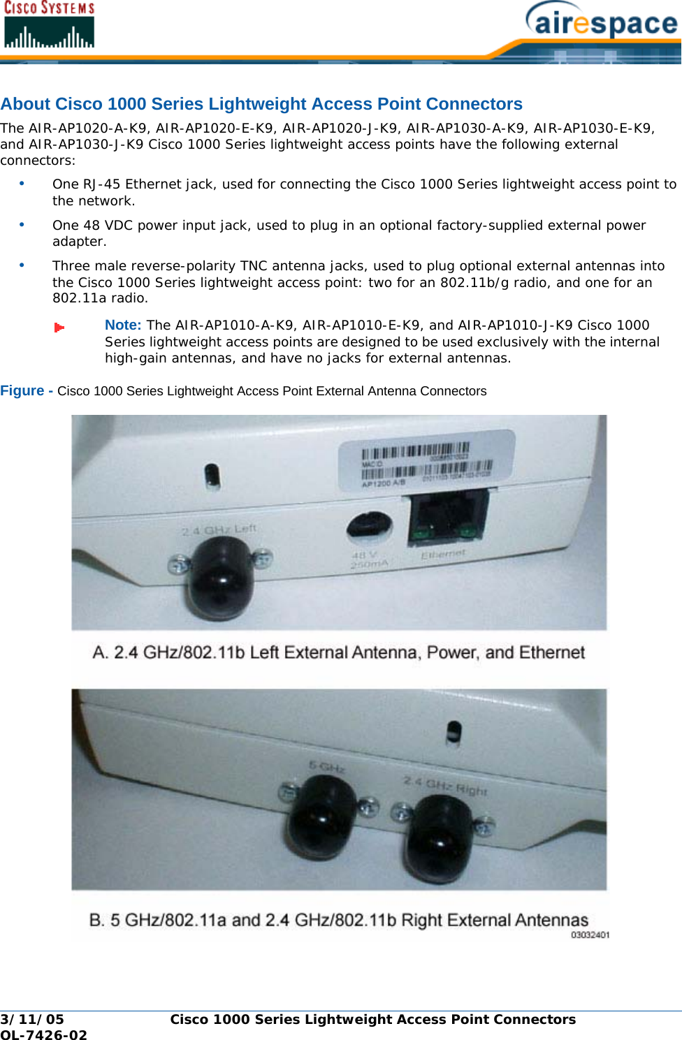
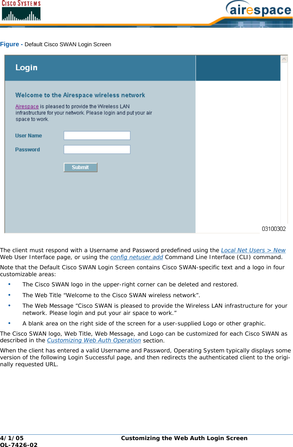
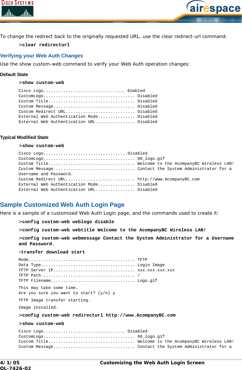
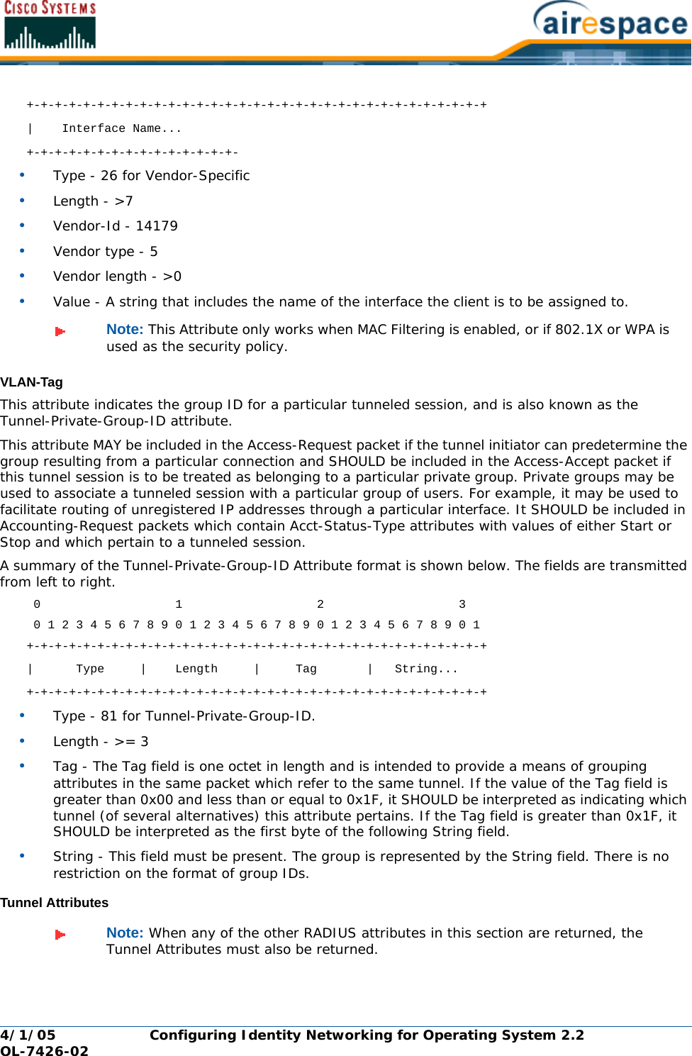
![4/1/05 FCC Statements for Cisco 1000 Series Lightweight Access Points OL-7426-02FCC Statements for Cisco 1000 Series Lightweight Access PointsFCC Statements for Cisco 1000 Series Lightweight Access PointsThis section includes the following FCC statements for Cisco 1000 Series lightweight access points:•Class A Statement •RF Radiation Hazard Warning •Non-Modification Statement •Deployment Statement Class A StatementClass A StatementThis equipment has been tested and found to comply with the limits for a Class A digital device, pursuant to Part 15 of the FCC Rules. These limits are designed to provide reasonable protection against harmful interference when the equipment is operated in a commercial environment. This equipment generates, uses, and can radiate radio frequency energy and, if not installed and used in accordance with the instruction manual, may cause harmful interference to radio communications. Operation of this equipment in a residential area is likely to cause harmful interference in which case the user will be required to correct the interference at his own expense. [cfr reference 15.105]RF Radiation Hazard WarningRF Radiation Hazard WarningTo ensure compliance with FCC RF exposure requirements, this device must be installed in a location such that the antenna of the device will be greater than 20 cm (8 in.) from all persons. Using higher gain antennas and types of antennas not covered under the FCC certification of this product is not allowed. Installers of the radio and end users of the Cisco Structured Wireless-Aware Network must adhere to the installation instructions provided in this manual.Non-Modification StatementNon-Modification StatementUse only the supplied internal antenna, or external antennas supplied by the manufacturer. Unautho-rized antennas, modifications, or attachments could damage the badge and could violate FCC regulations and void the user’s authority to operate the equipment.Deployment StatementDeployment StatementThis product is certified for indoor deployment only. Do not install or use this product outdoors.Note: Refer to the Cisco SWAN Release Notes for 802.11a external antenna informa-tion. Contact Cisco for a list of FCC-approved 802.11a and 802.11b/g external antennas.](https://usermanual.wiki/Cisco-Systems/102057/User-Guide-566510-Page-13.png)
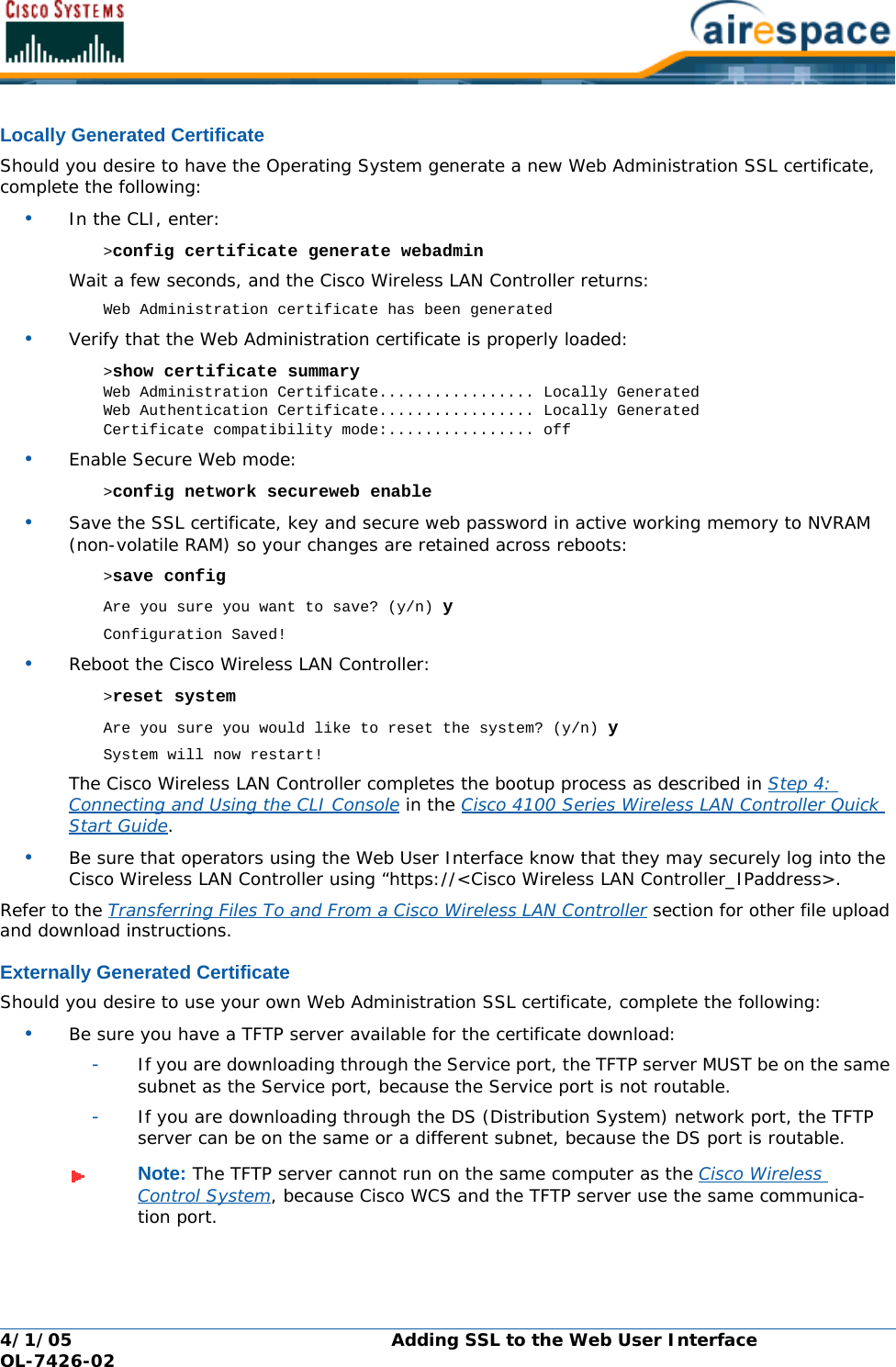
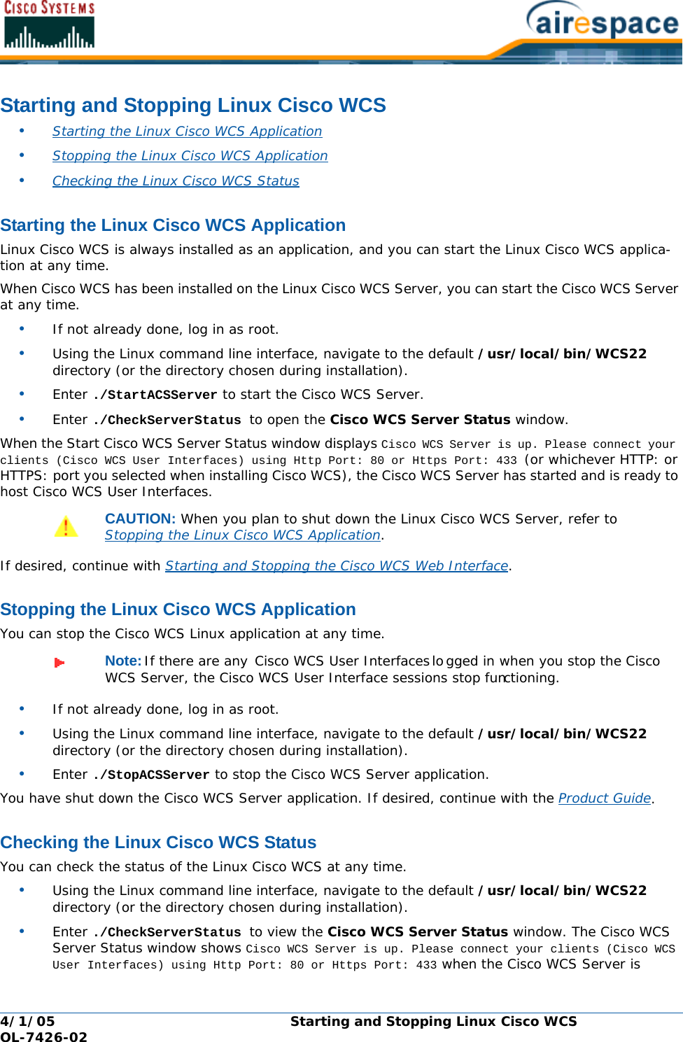
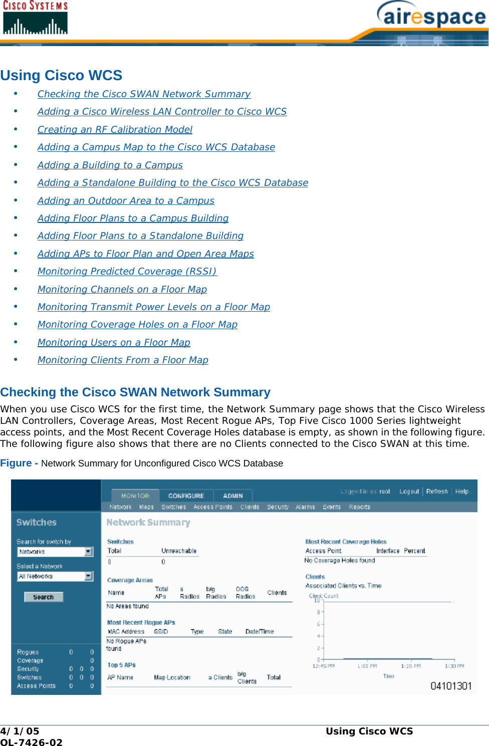
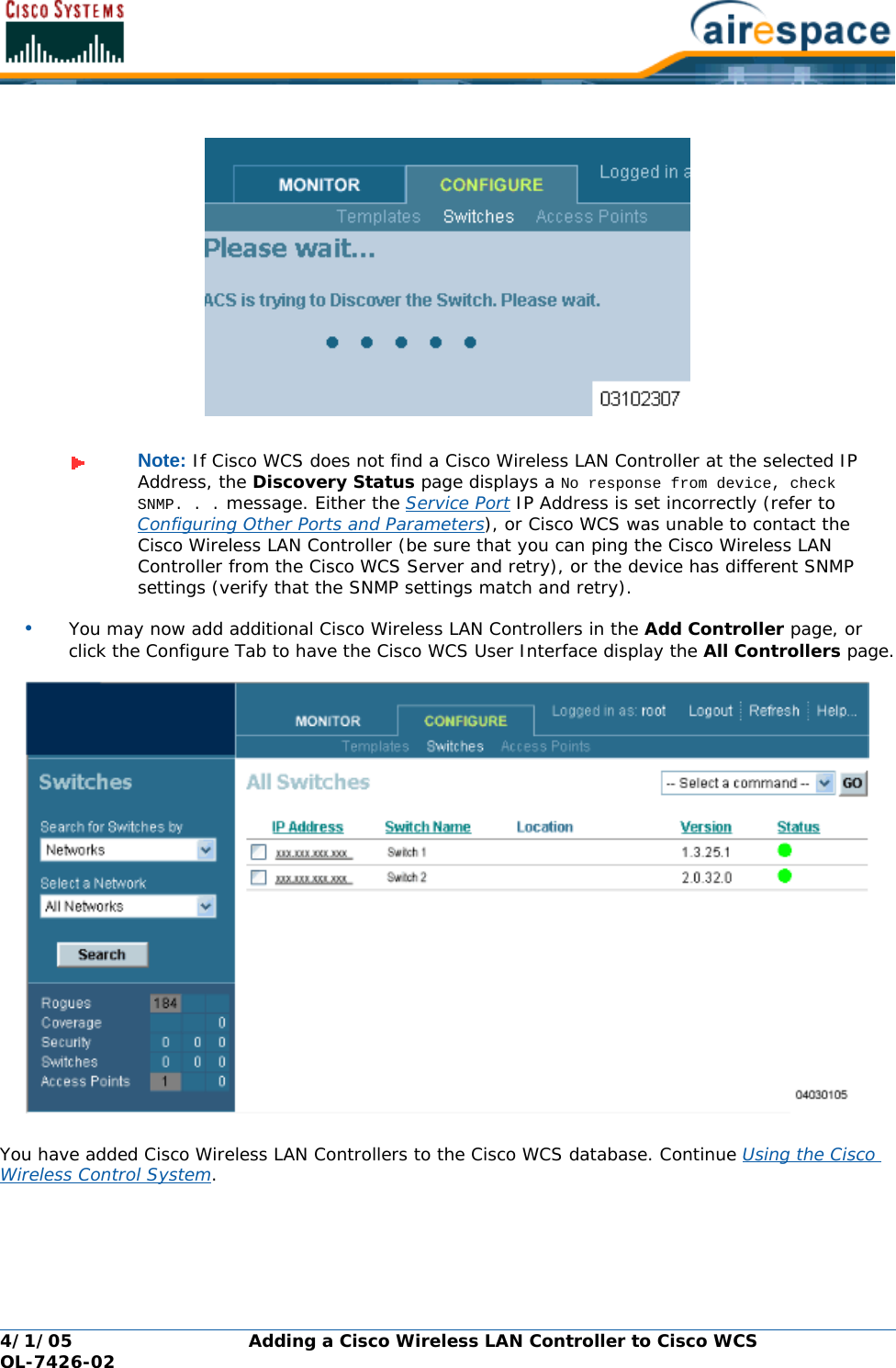
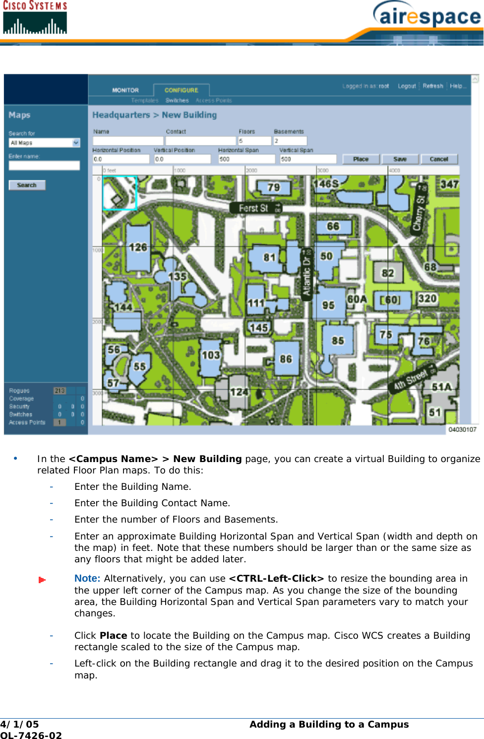
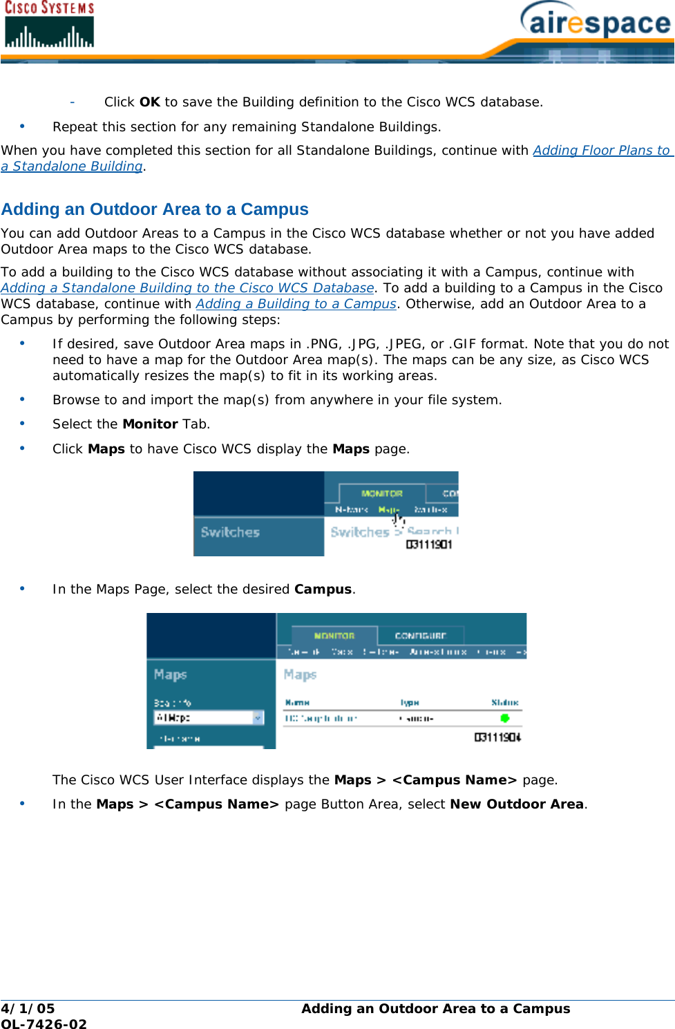
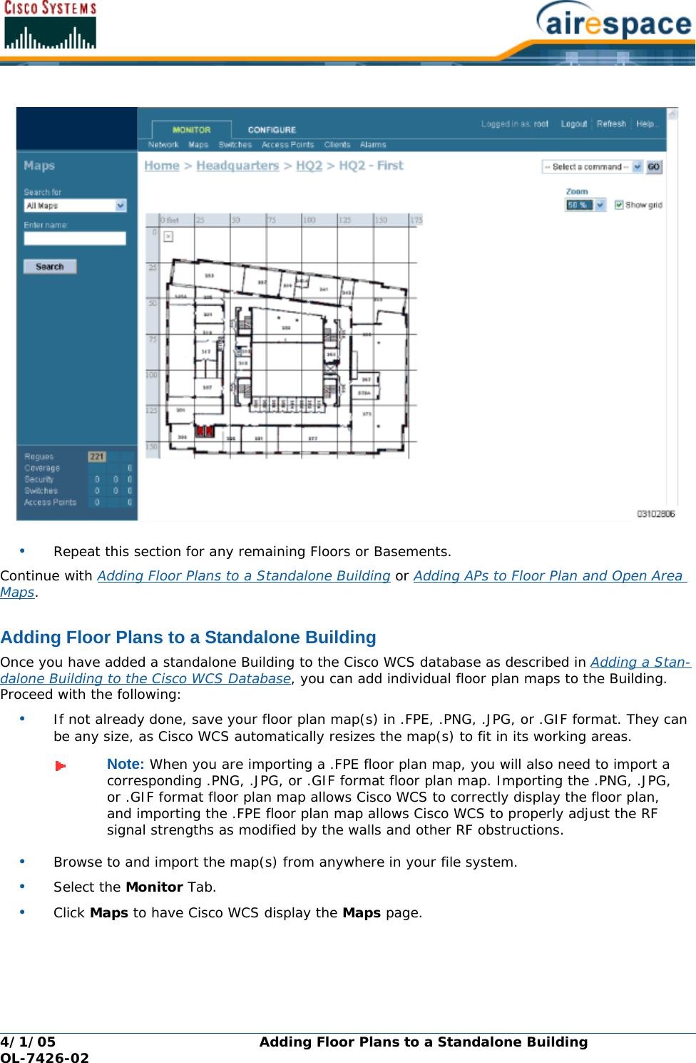
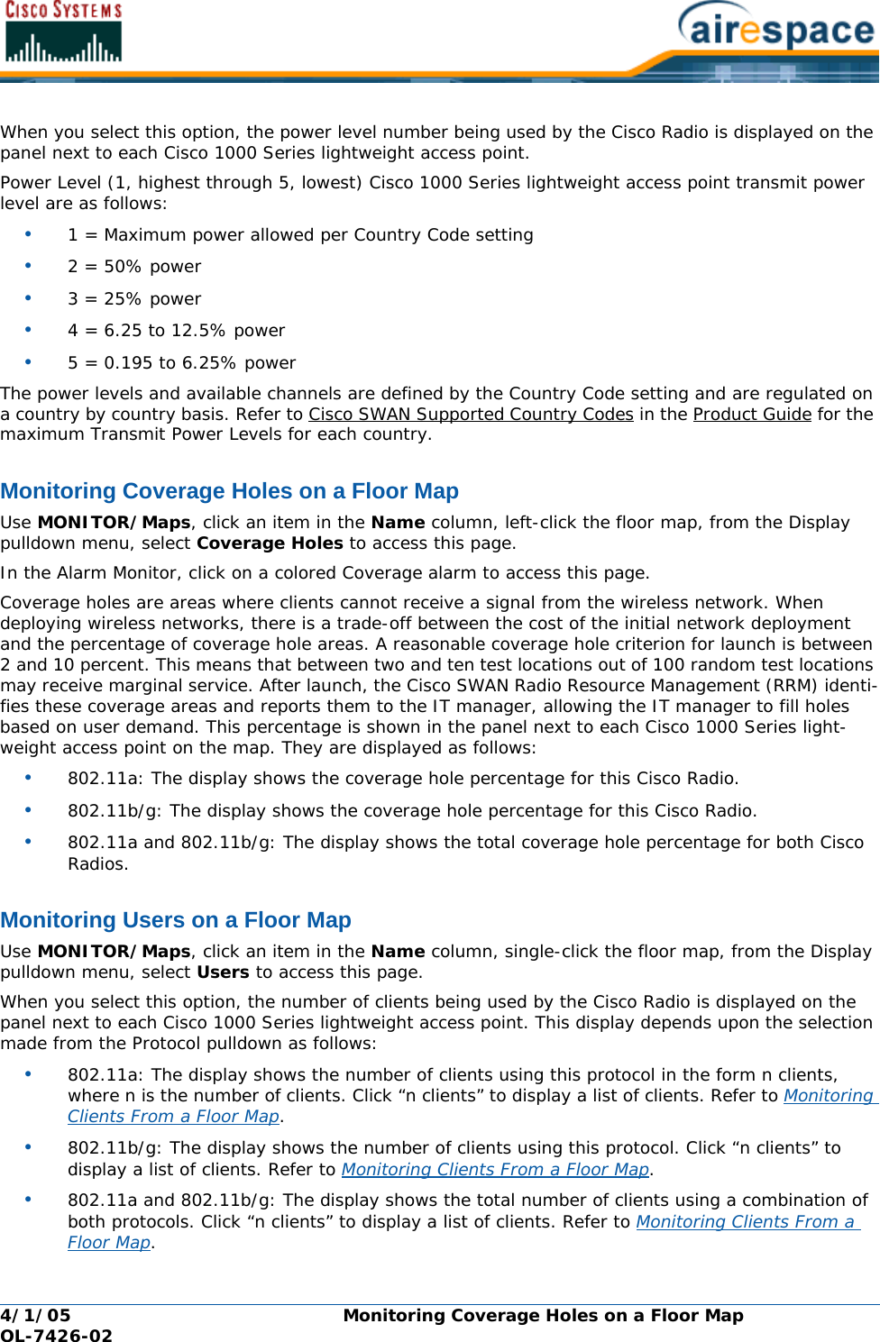
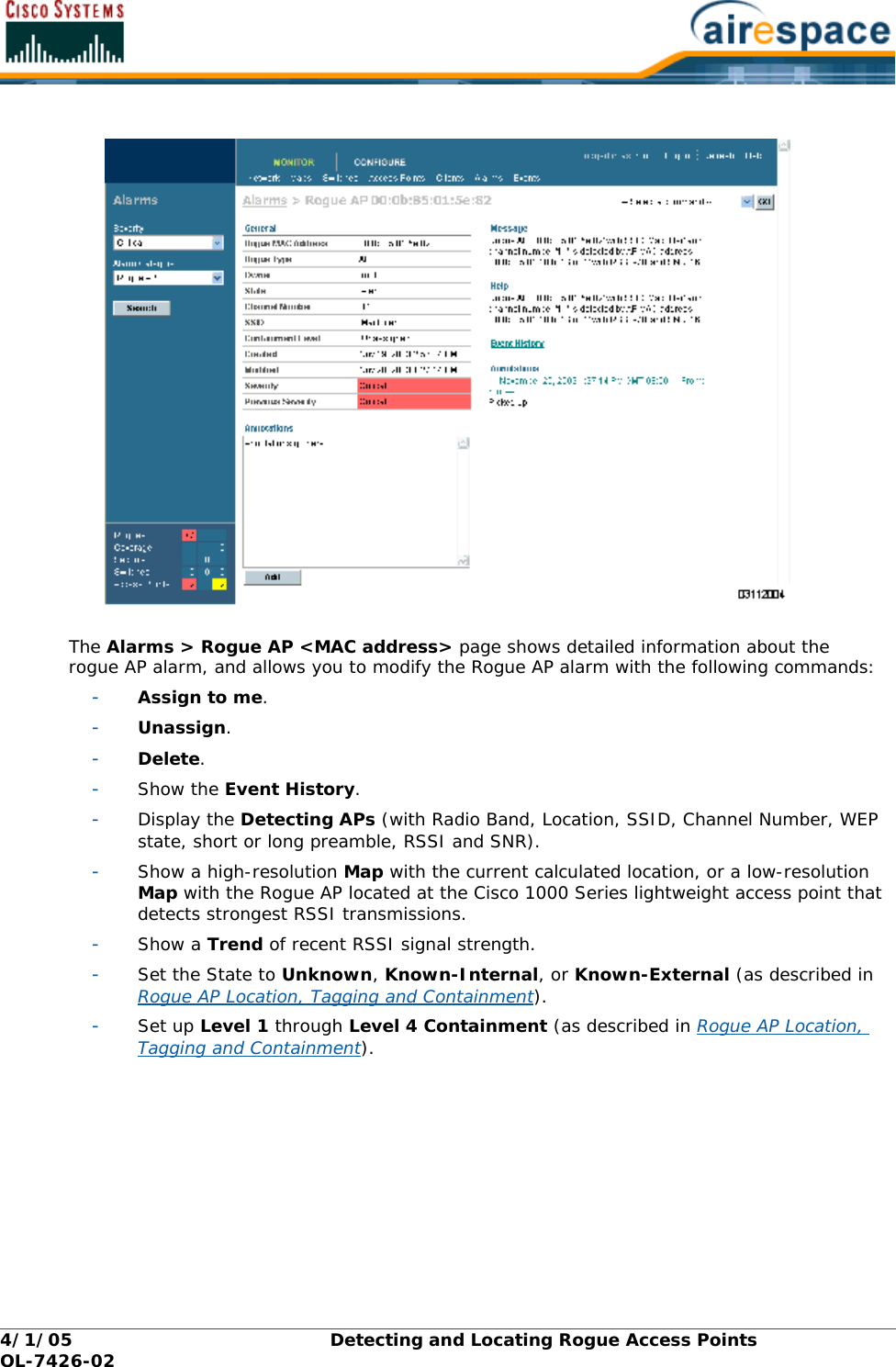
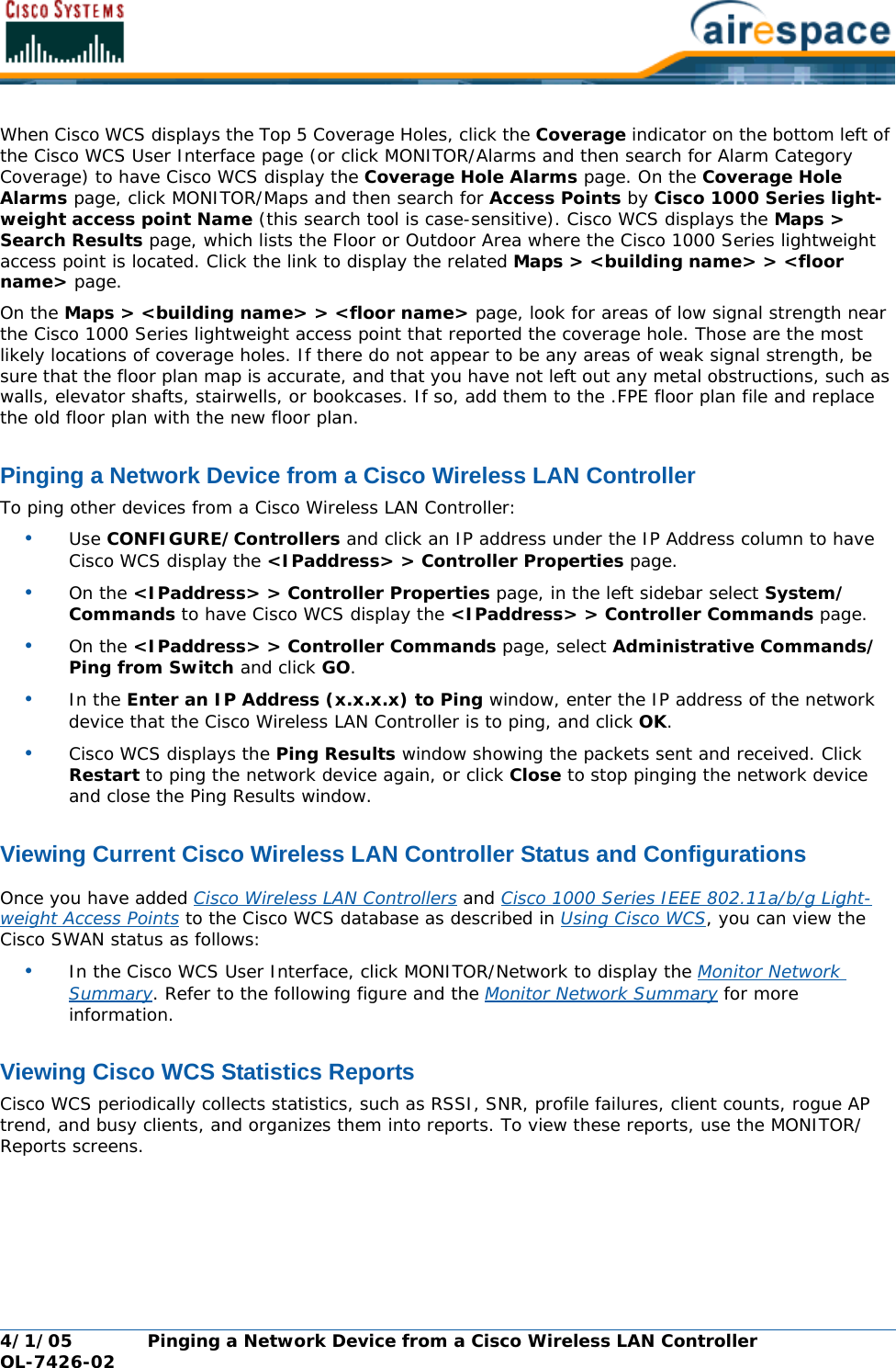
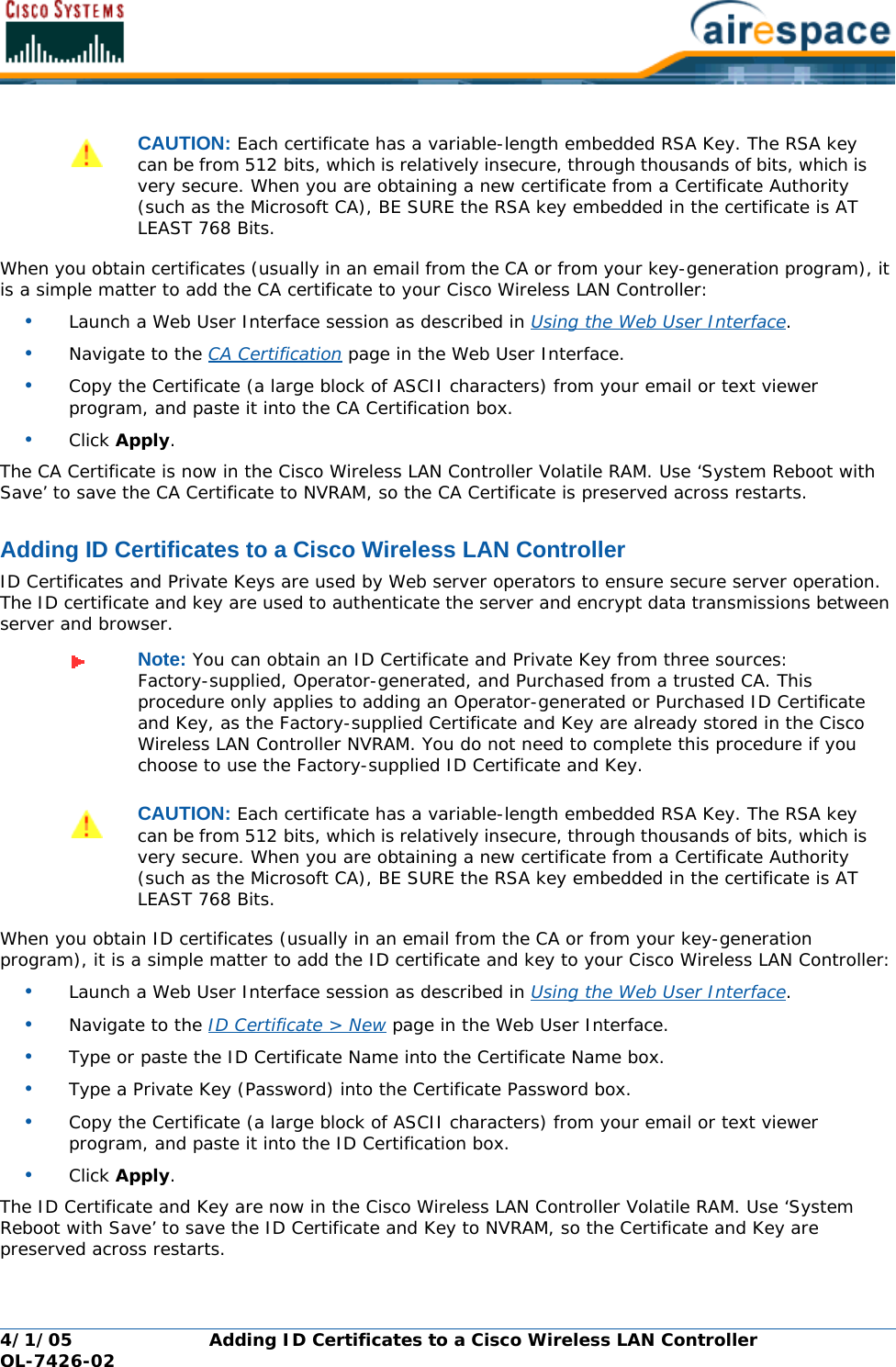
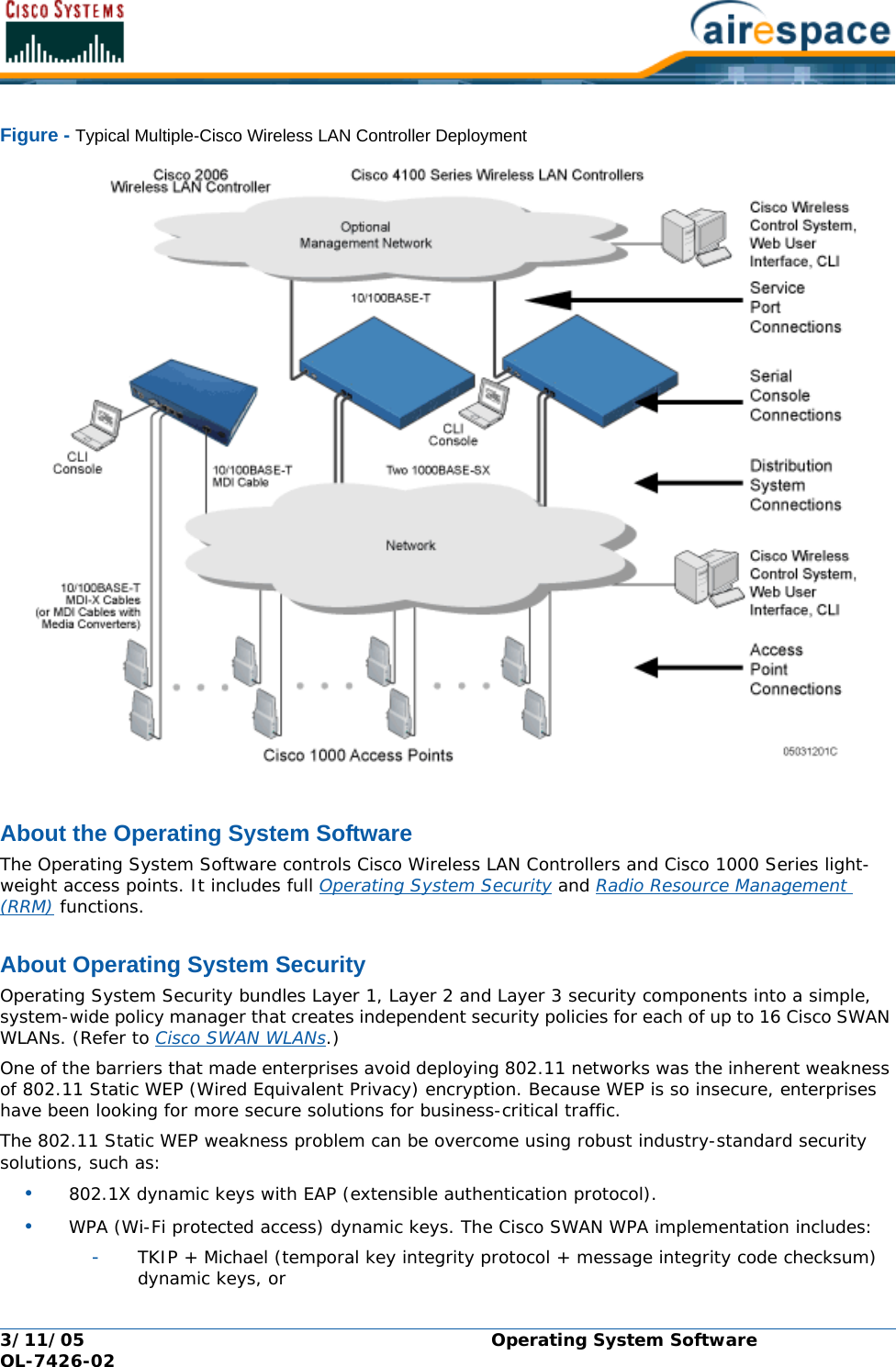
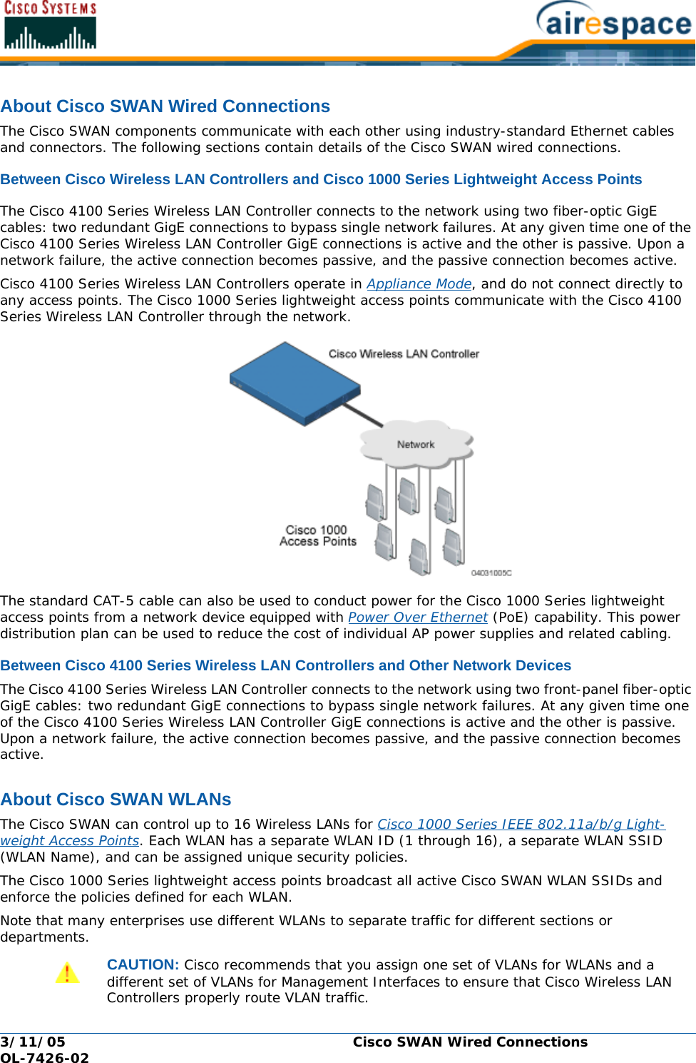
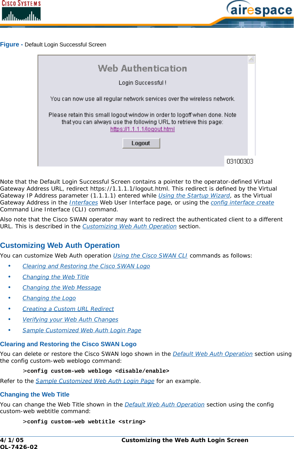
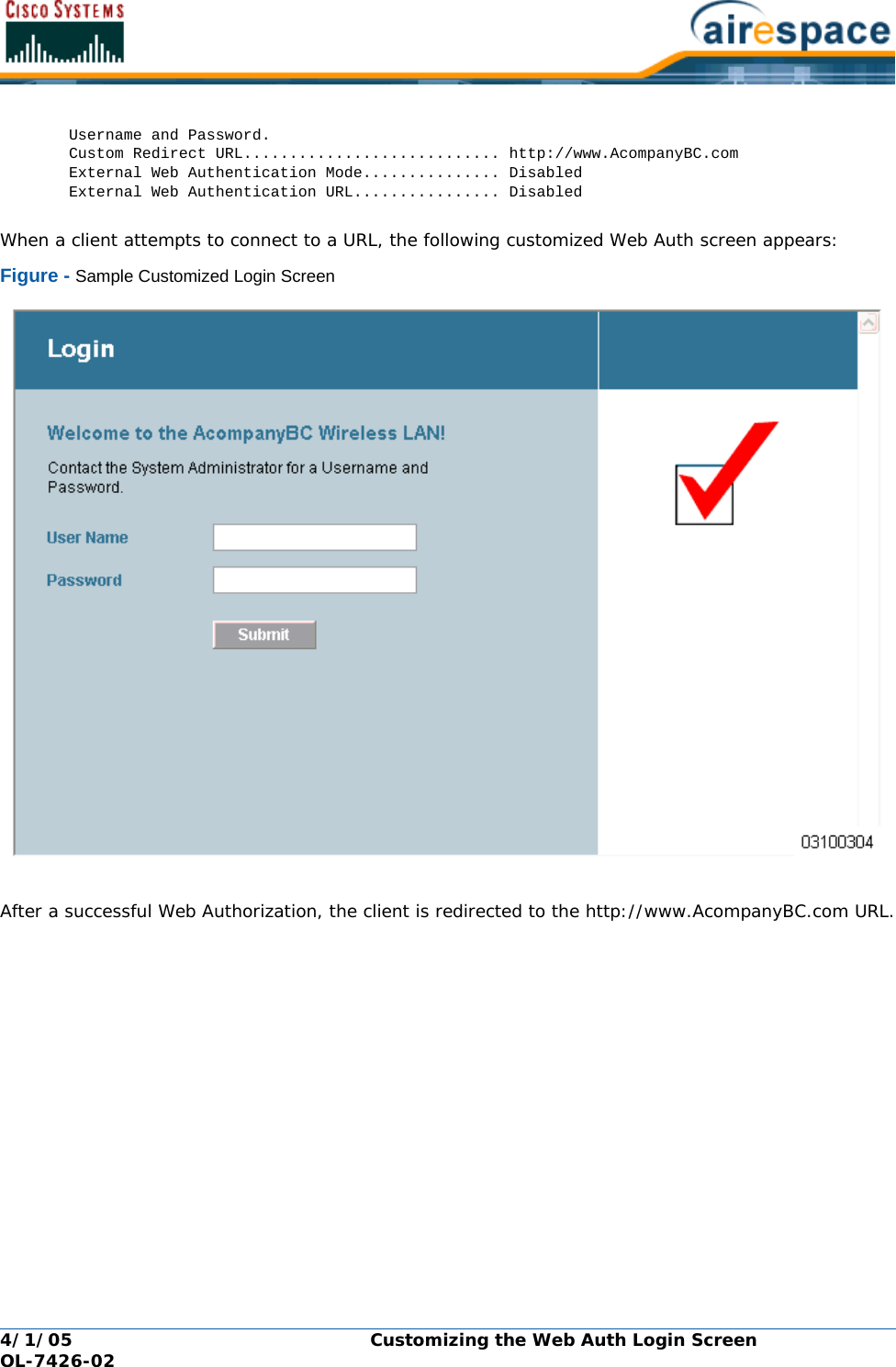
![4/1/05 FCC Statements for Cisco 4100 Series Wireless LAN Controllers OL-7426-02FCC Statements for Cisco 4100 Series Wireless LAN ControllersFCC Statements for Cisco 4100 Series Wireless LAN ControllersThis equipment has been tested and found to comply with the limits for a Class A digital device, pursuant to Part 15 of the FCC Rules. These limits are designed to provide reasonable protection against harmful interference when the equipment is operated in a commercial environment. This equipment generates, uses, and can radiate radio frequency energy and, if not installed and used in accordance with the instruction manual, may cause harmful interference to radio communications. Operation of this equipment in a residential area is likely to cause harmful interference in which case the user will be required to correct the interference at his own expense. [cfr reference 15.105]](https://usermanual.wiki/Cisco-Systems/102057/User-Guide-566510-Page-15.png)
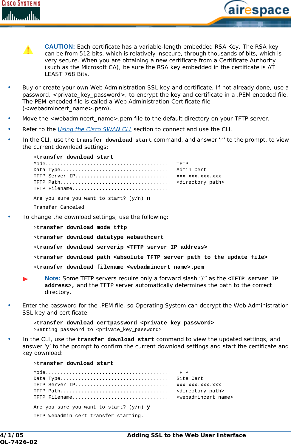
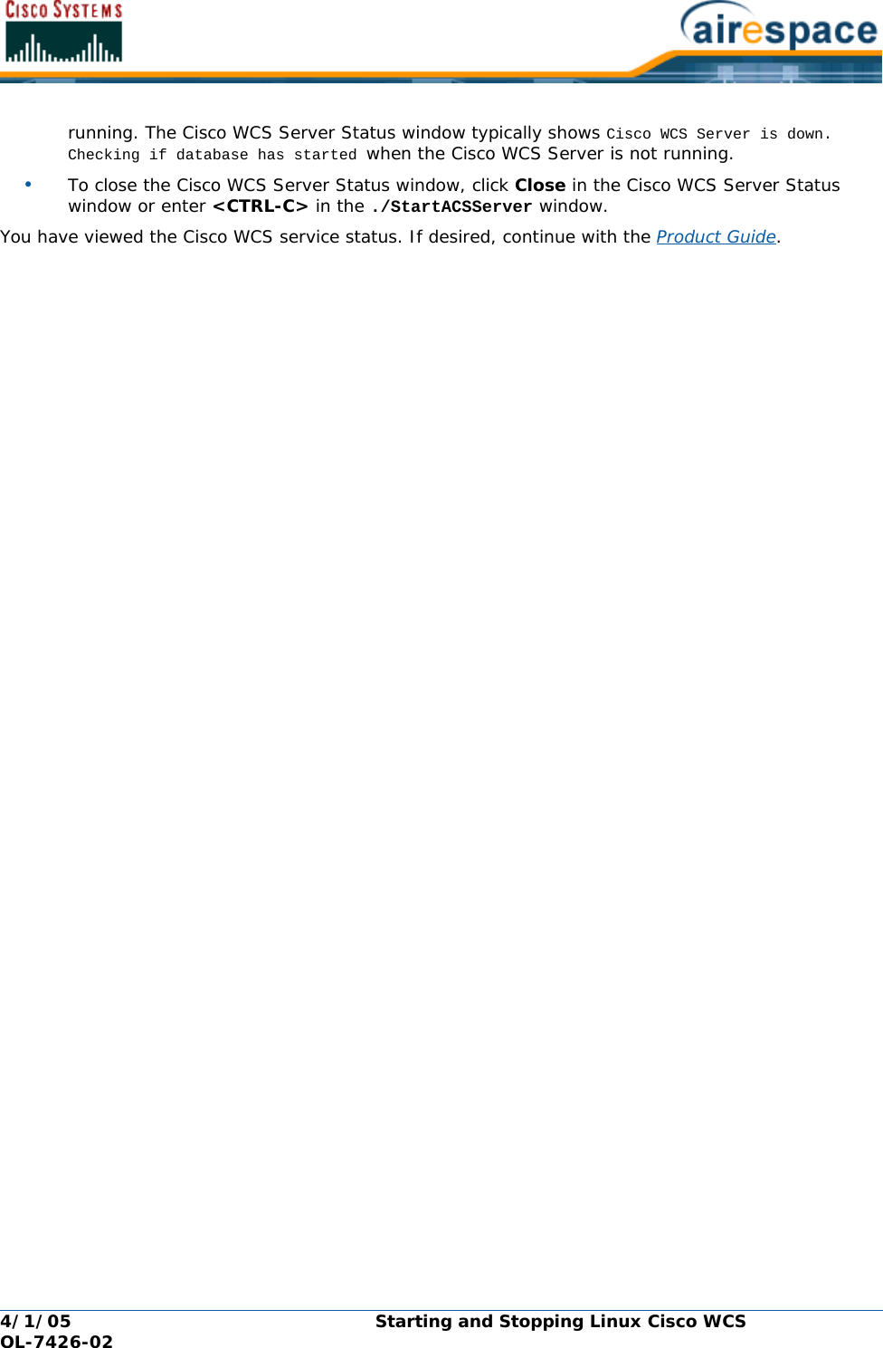
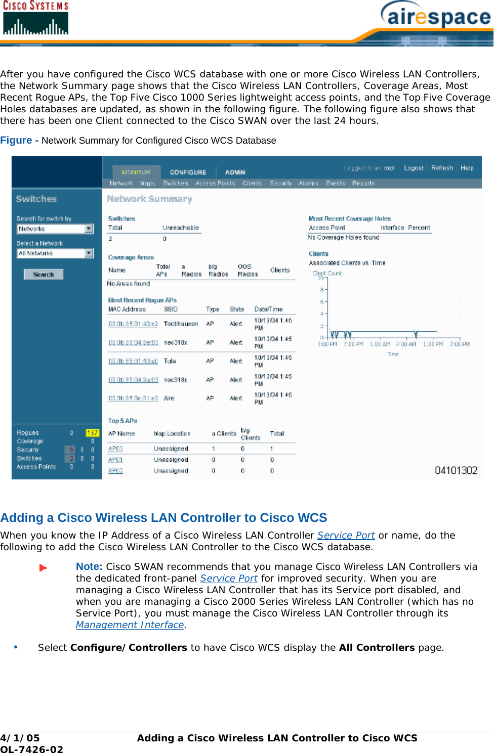
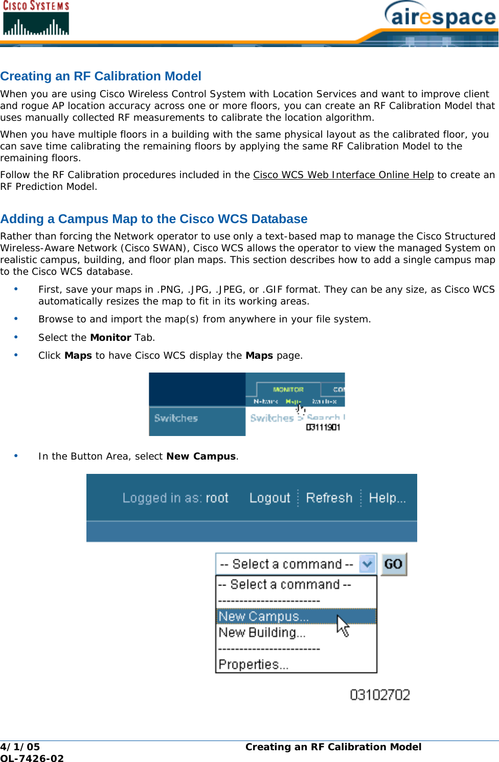
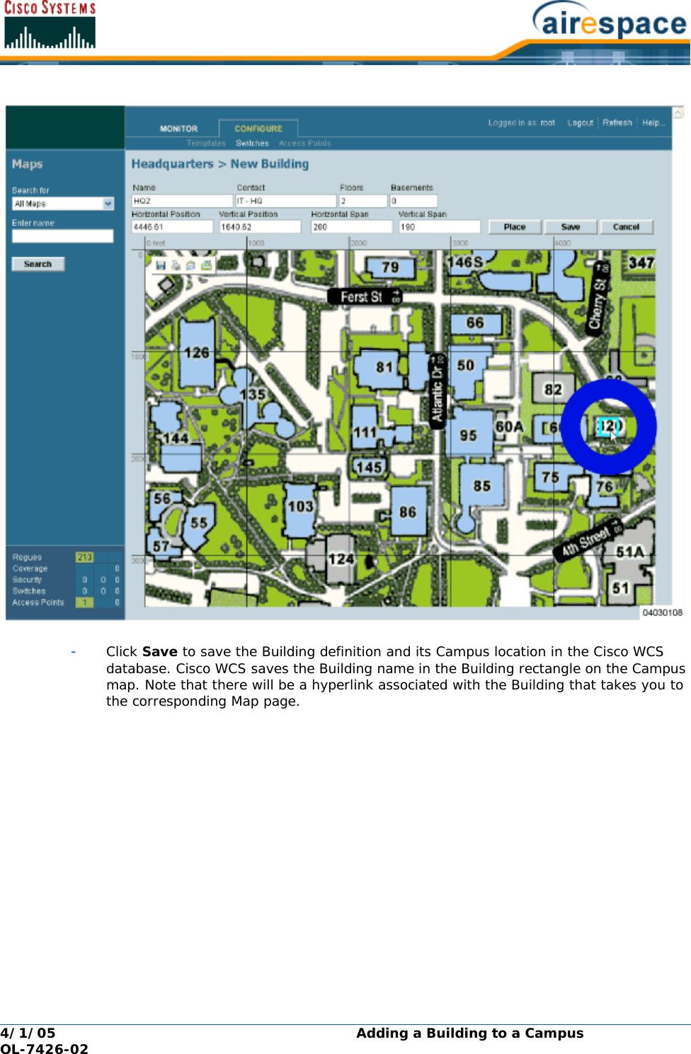
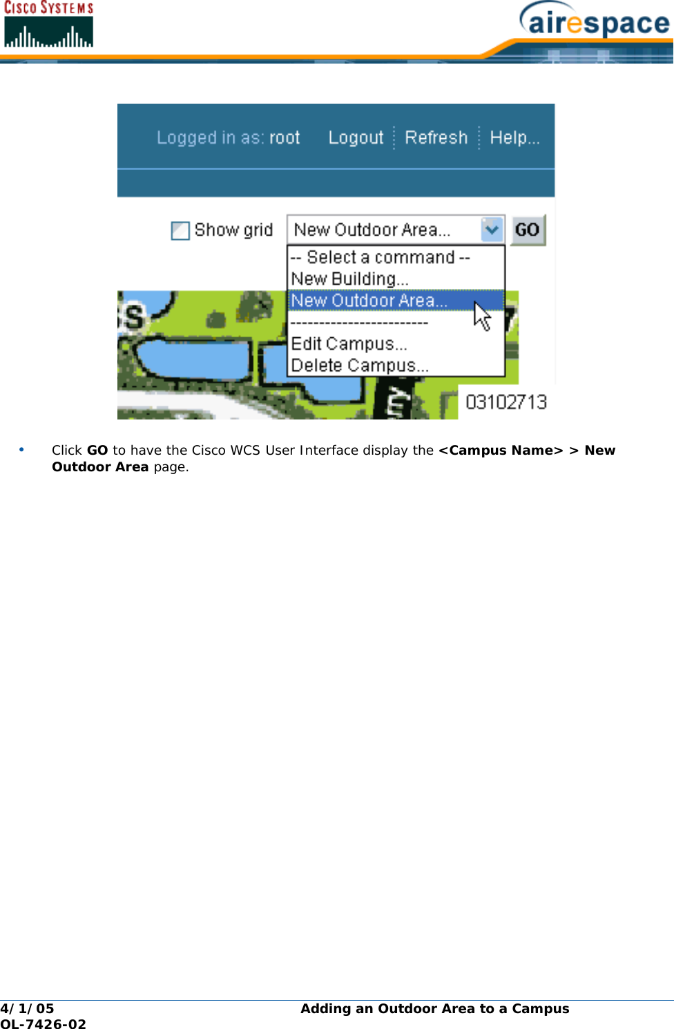
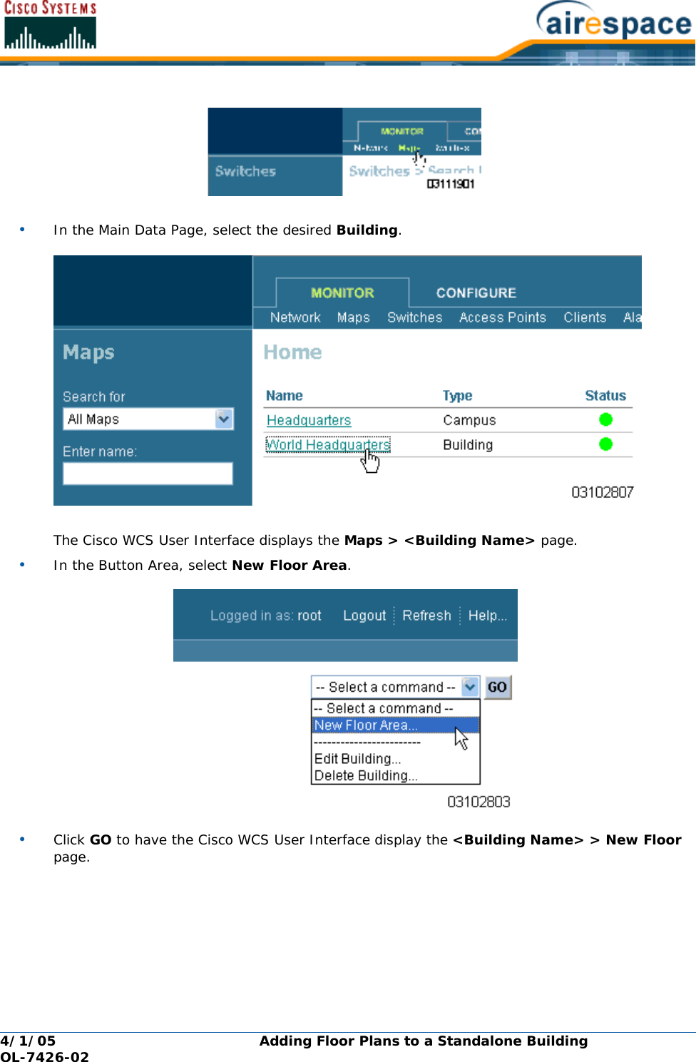
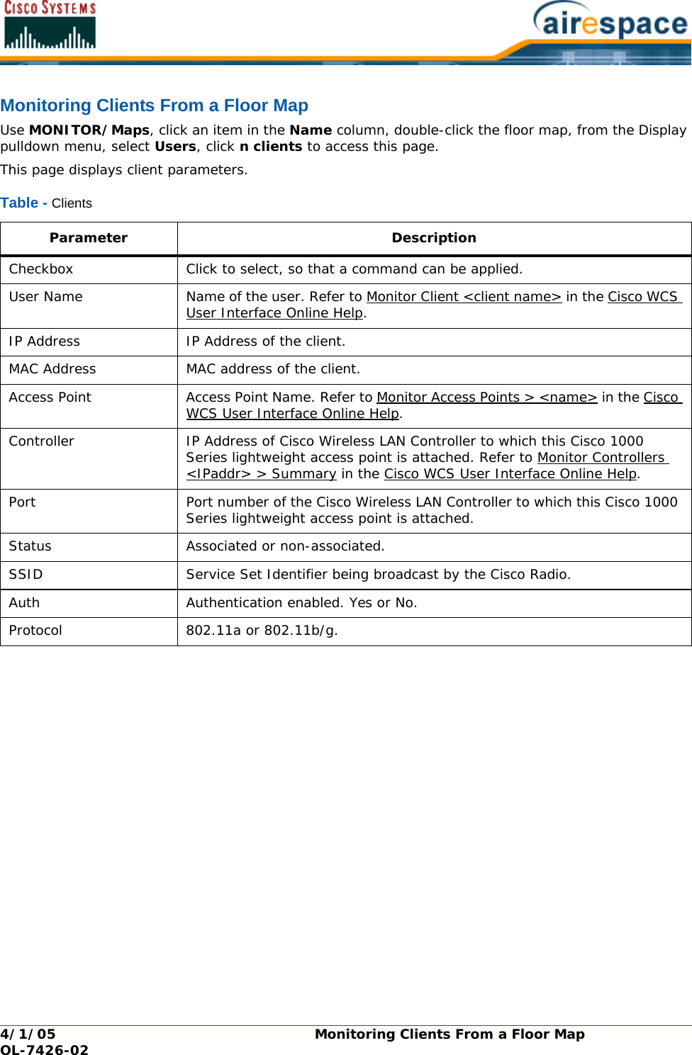
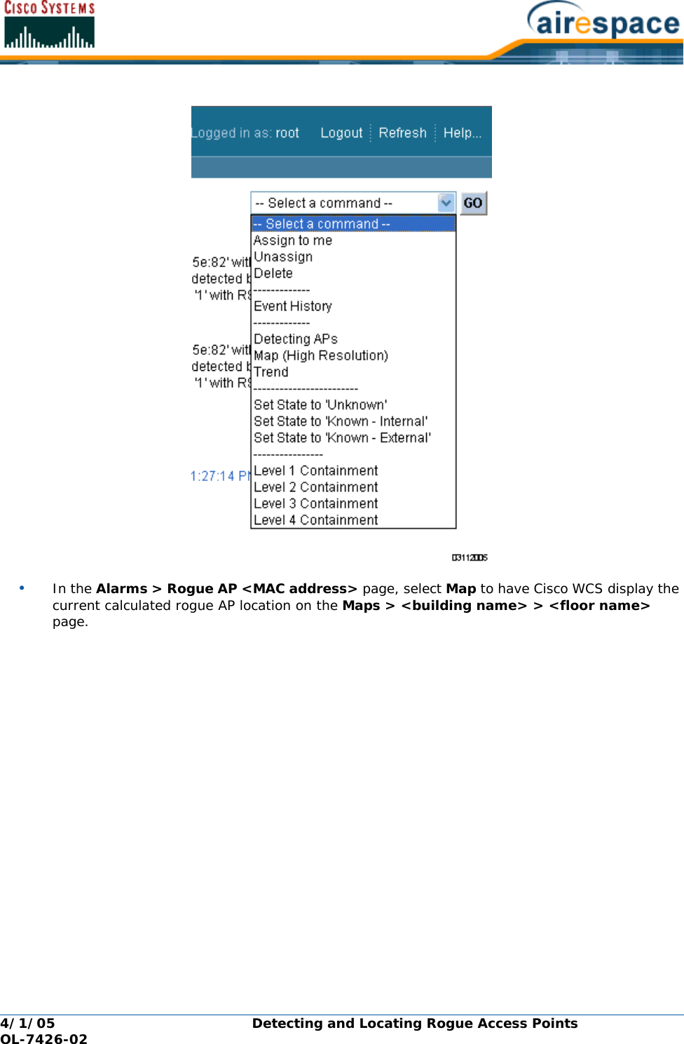
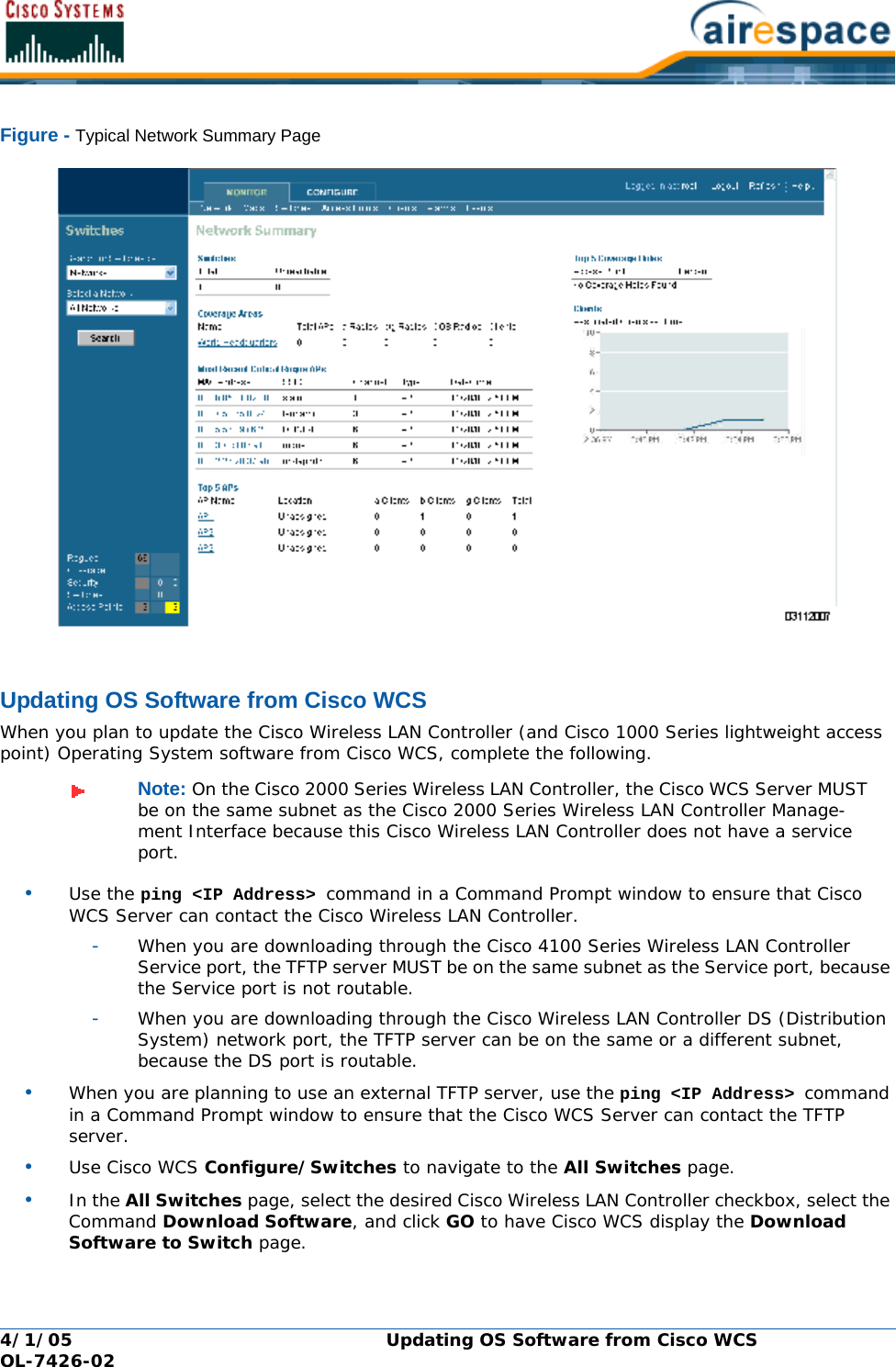
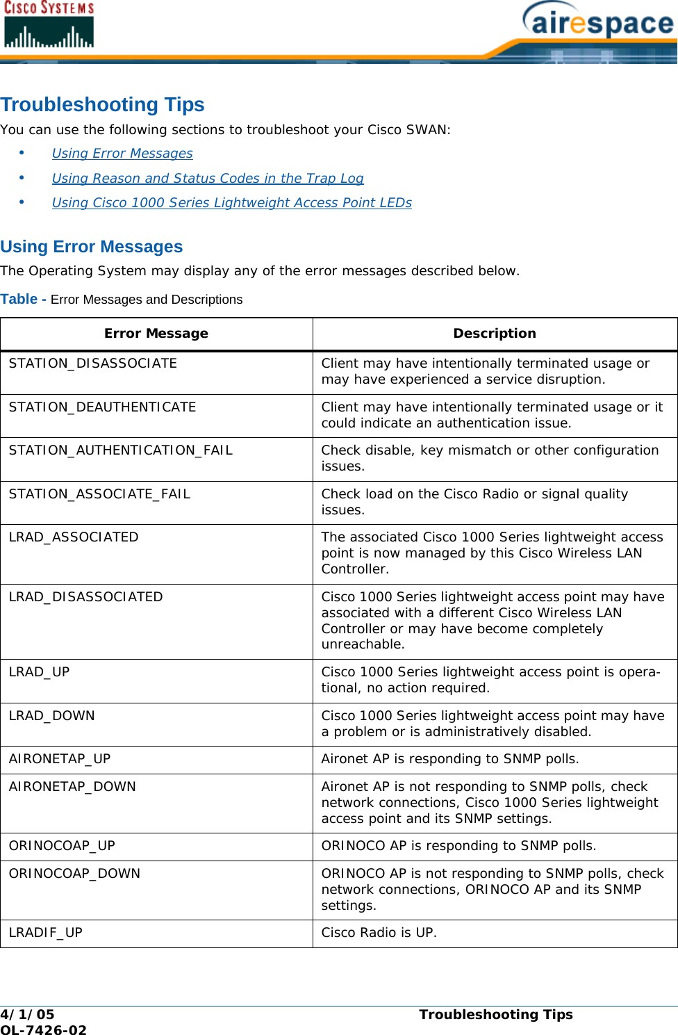
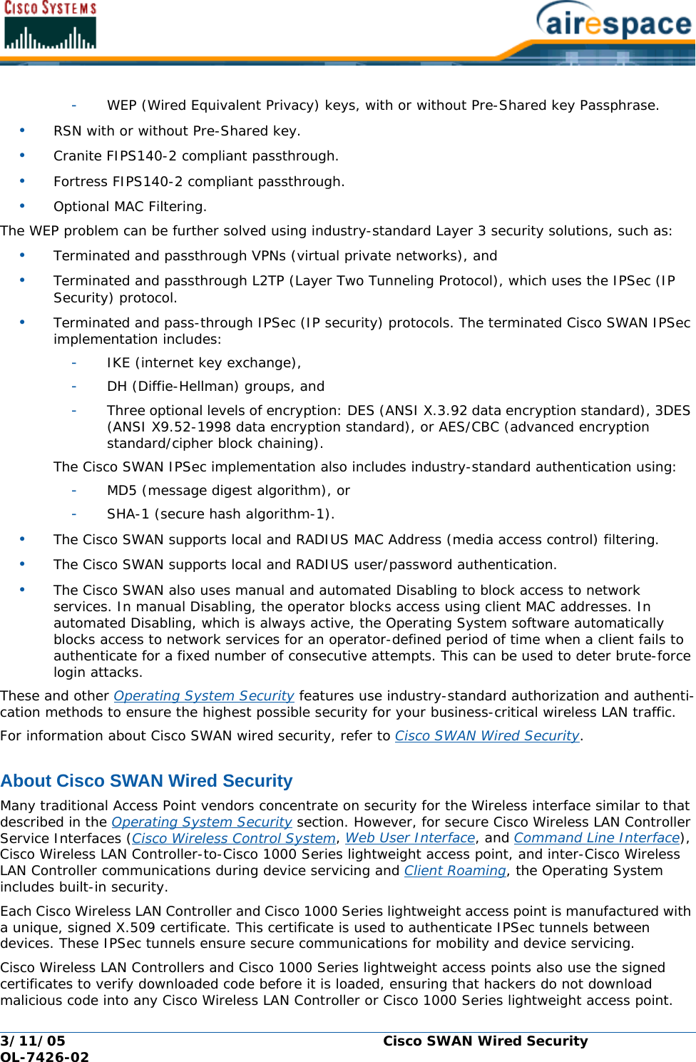
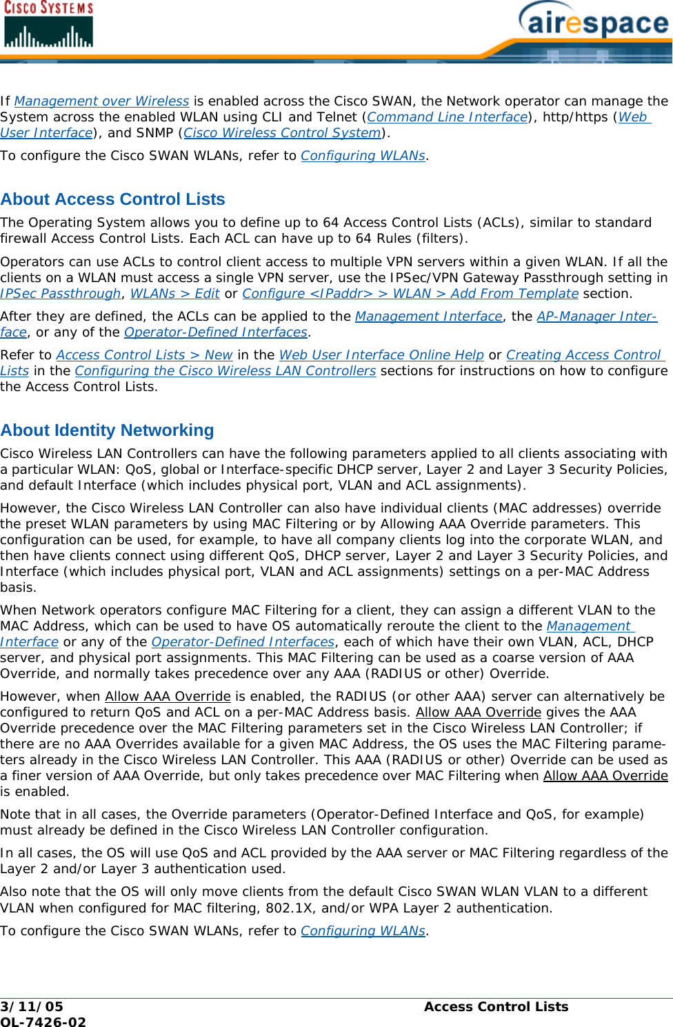
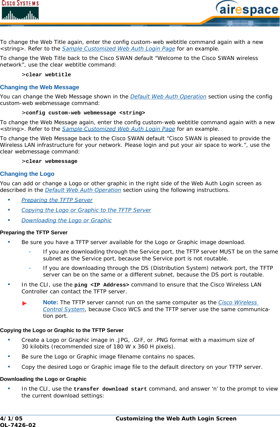
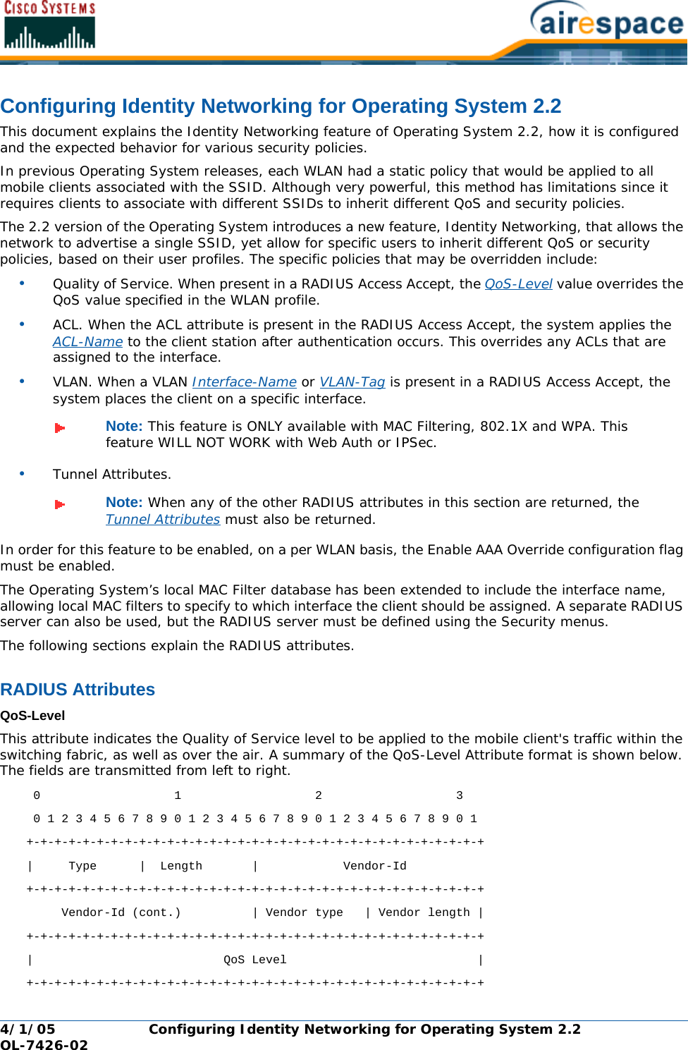
![4/1/05 FCC Statements for Cisco 2000 Series Wireless LAN Controllers OL-7426-02FCC Statements for Cisco 2000 Series Wireless LAN ControllersFCC Statements for Cisco 2000 Series Wireless LAN ControllersThis equipment has been tested and found to comply with the limits for a Class B digital device, pursuant to Part 15 of the FCC Rules. These limits are designed to provide reasonable protection against harmful interference in a residential installation. This equipment generates, uses and can radiate radio frequency energy and, if not installed and used in accordance with the instructions, may cause harmful interference to radio communications. However, there is no guarantee that interference will not occur in a particular installation. If this equipment does cause harmful interference to radio or television reception, which can be determined by turning the equipment off and on, the user is encour-aged to try to correct the interference by one or more of the following measures:•Reorient or relocate the receiving antenna.•Increase the separation between the equipment and receiver.•Connect the equipment into an outlet on a circuit different from that to which the receiver is connected.•Consult the dealer or an experienced radio/TV technician for help. [cfr reference 15.105]](https://usermanual.wiki/Cisco-Systems/102057/User-Guide-566510-Page-16.png)


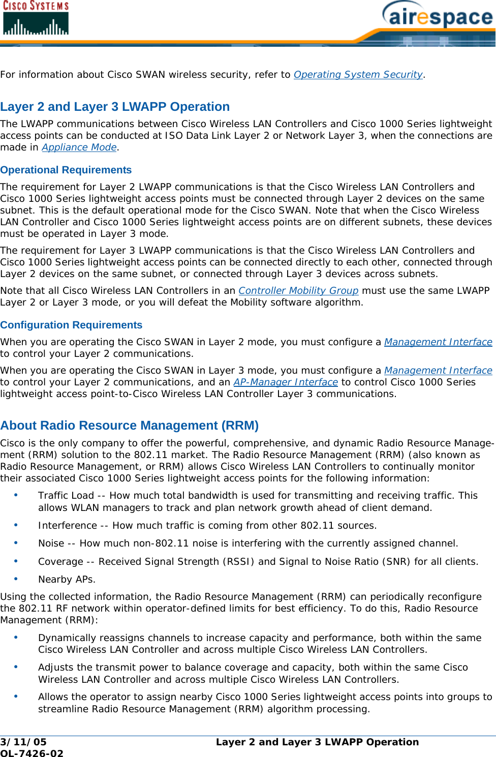
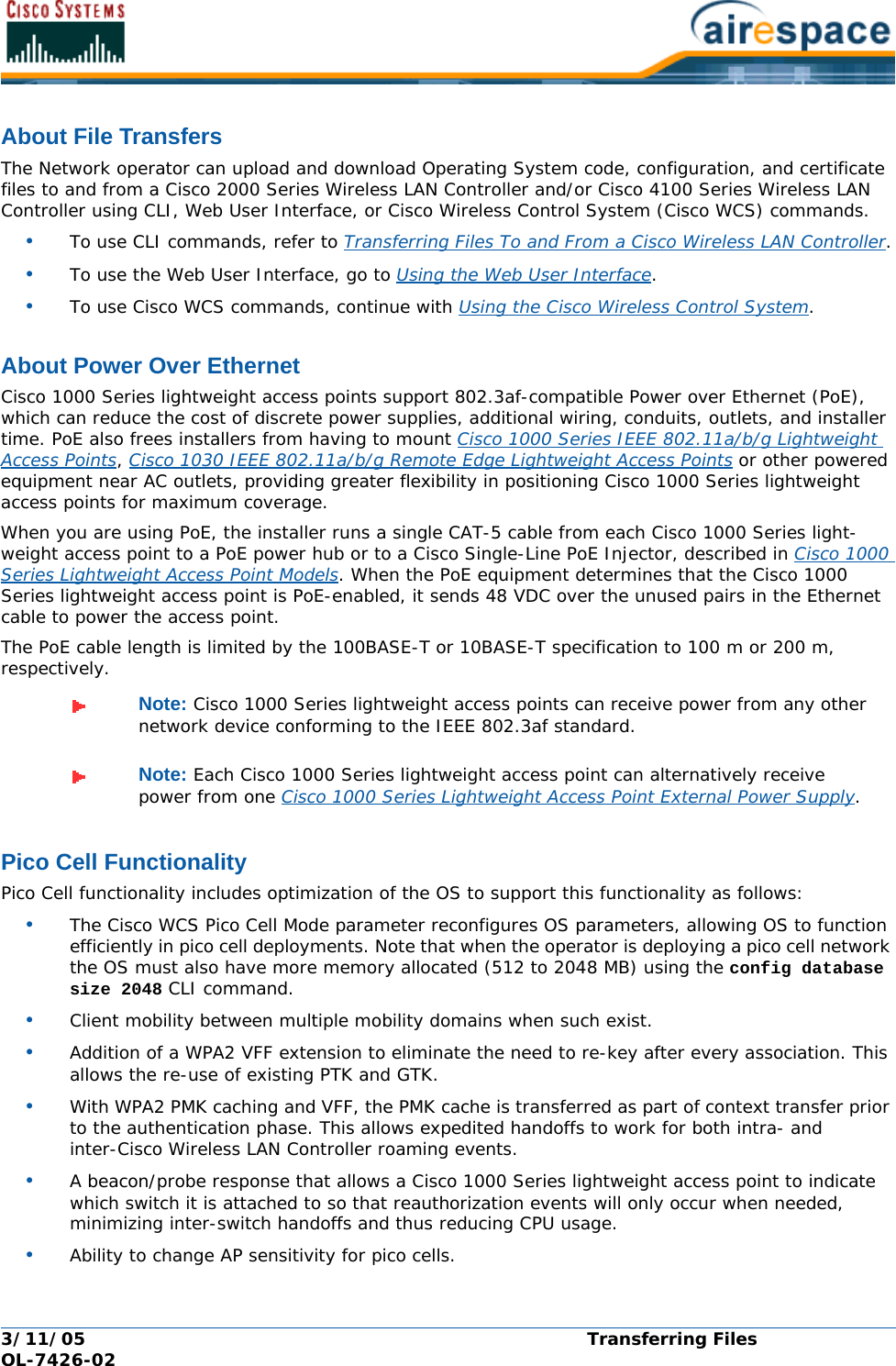
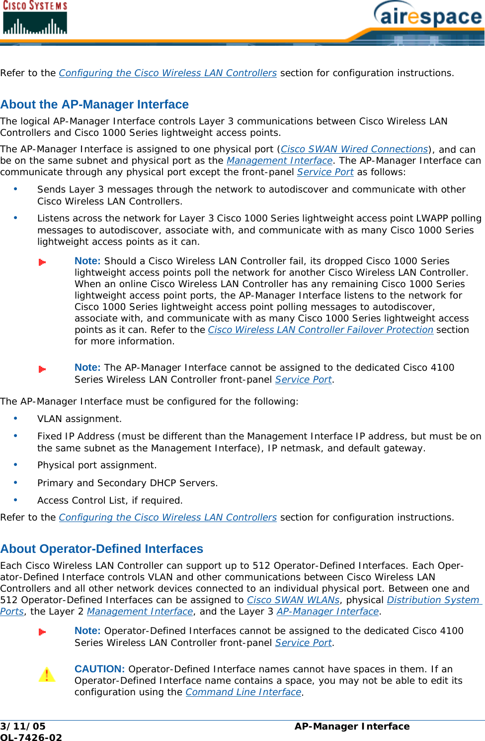


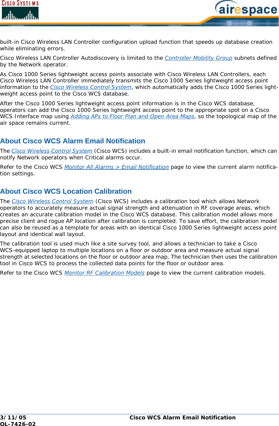

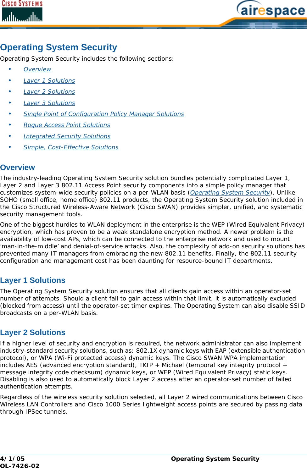
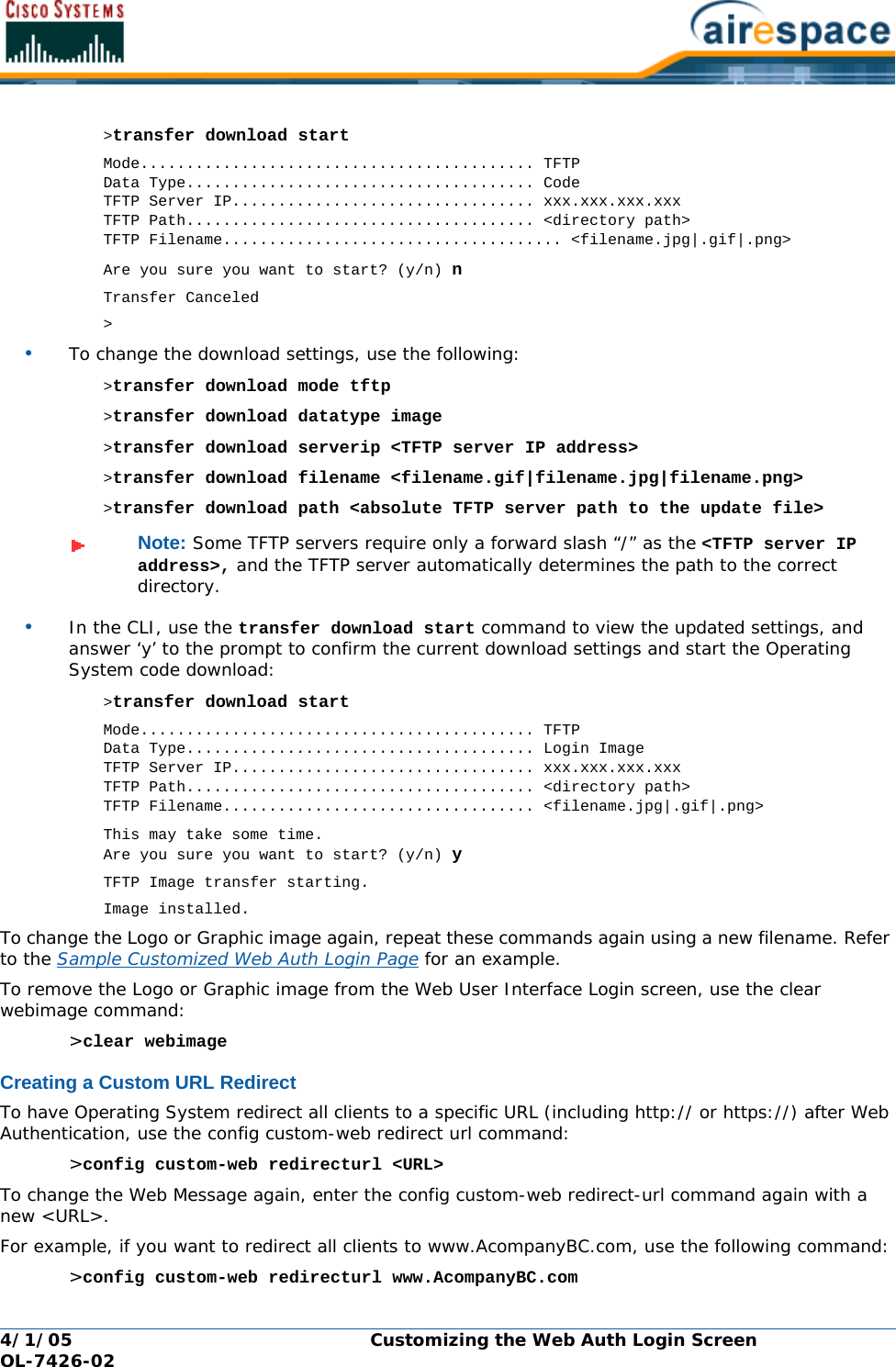
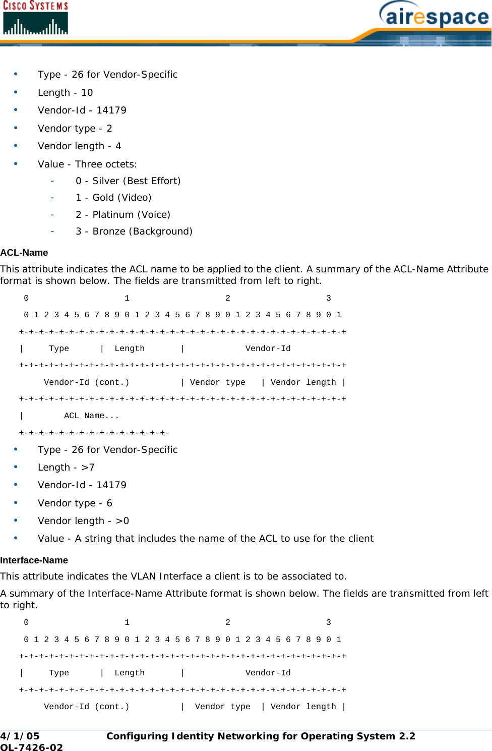
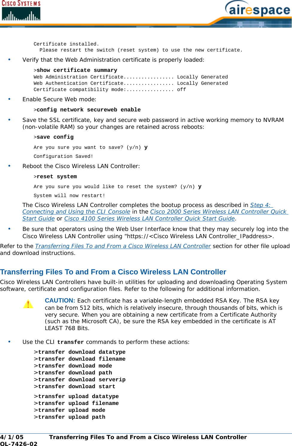
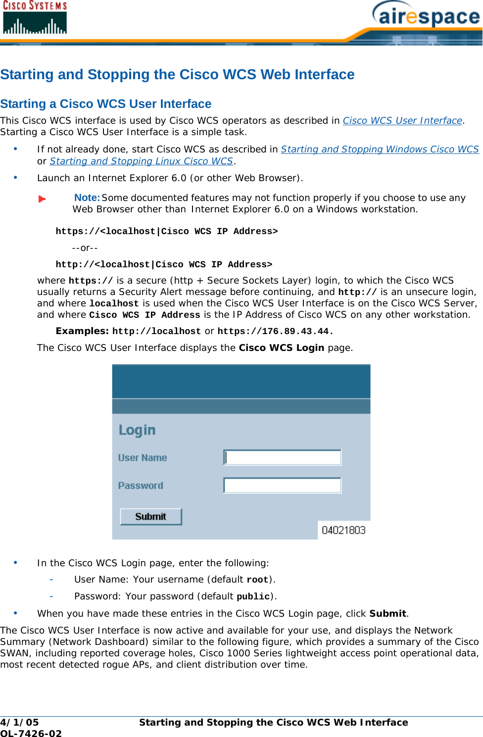
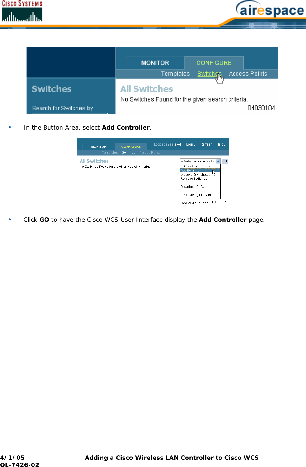
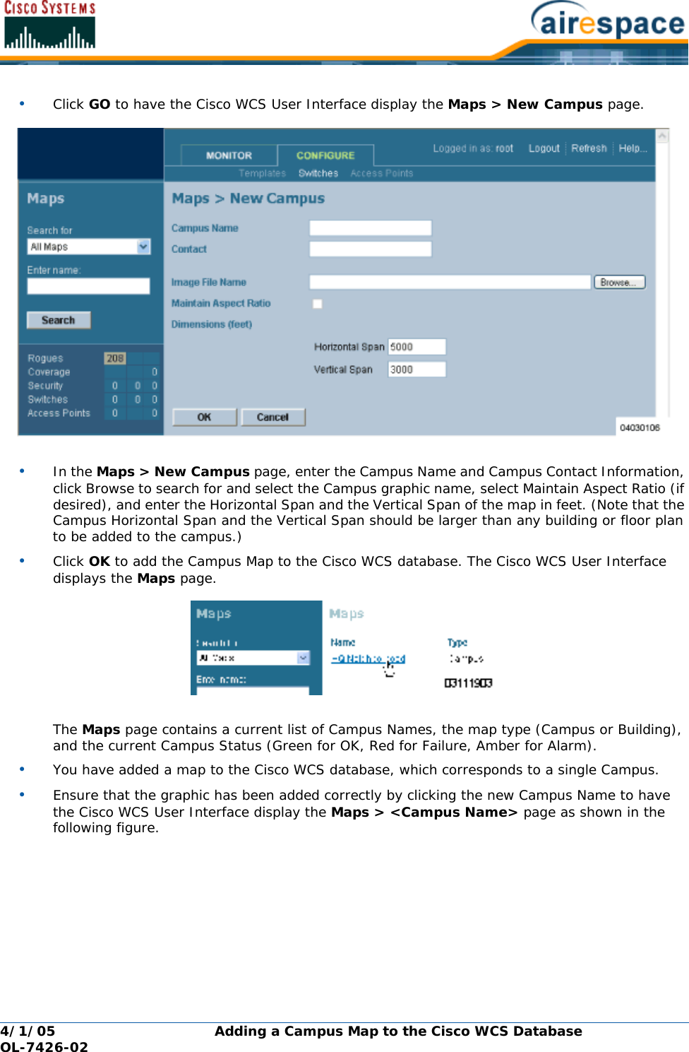
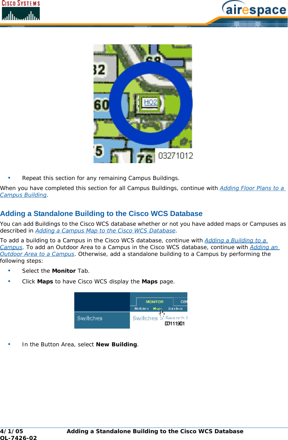
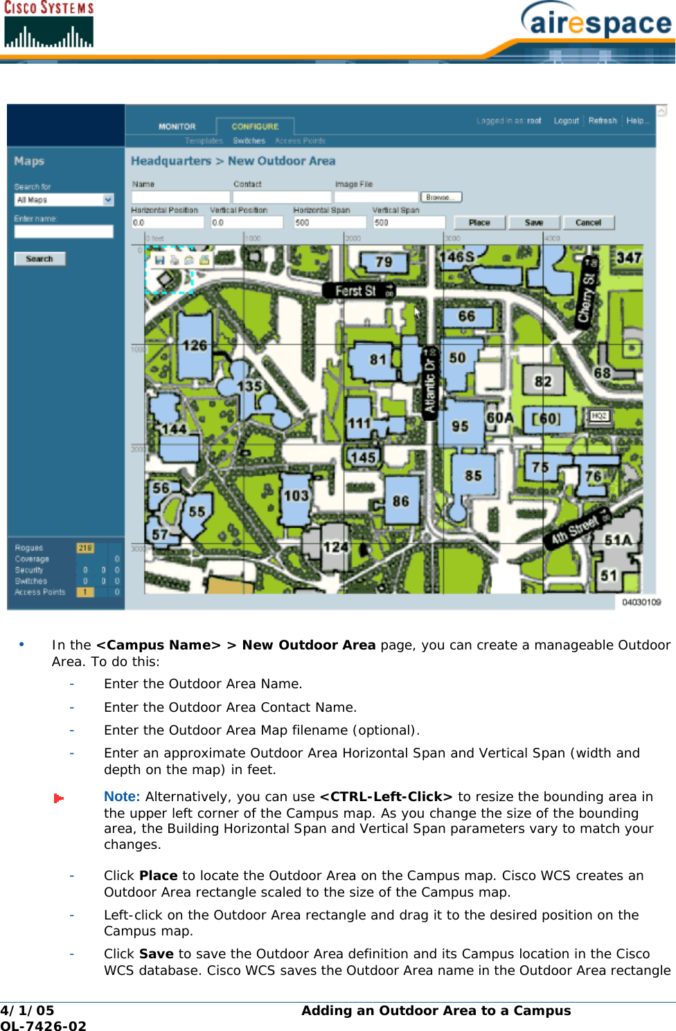
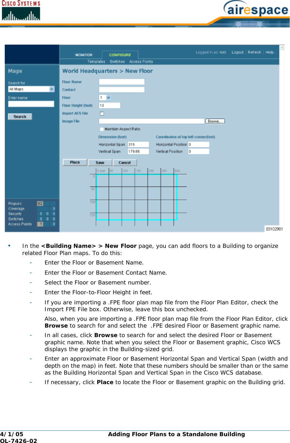
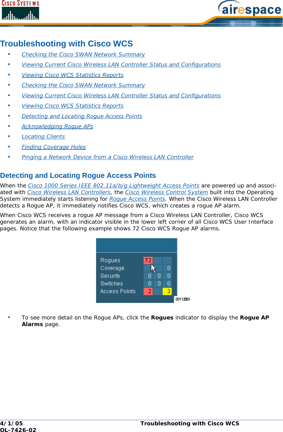
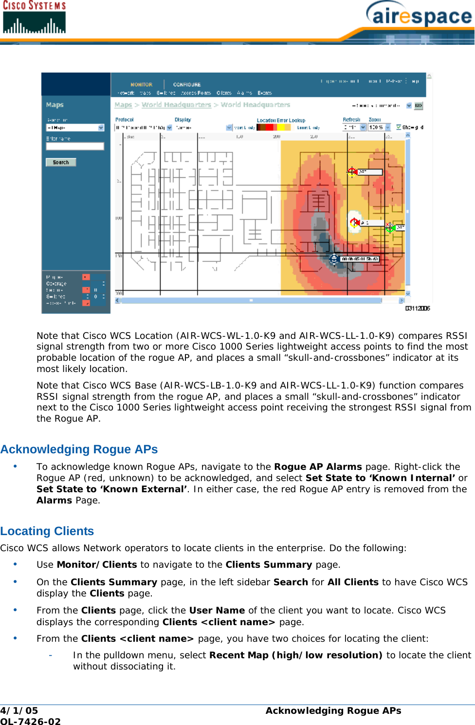
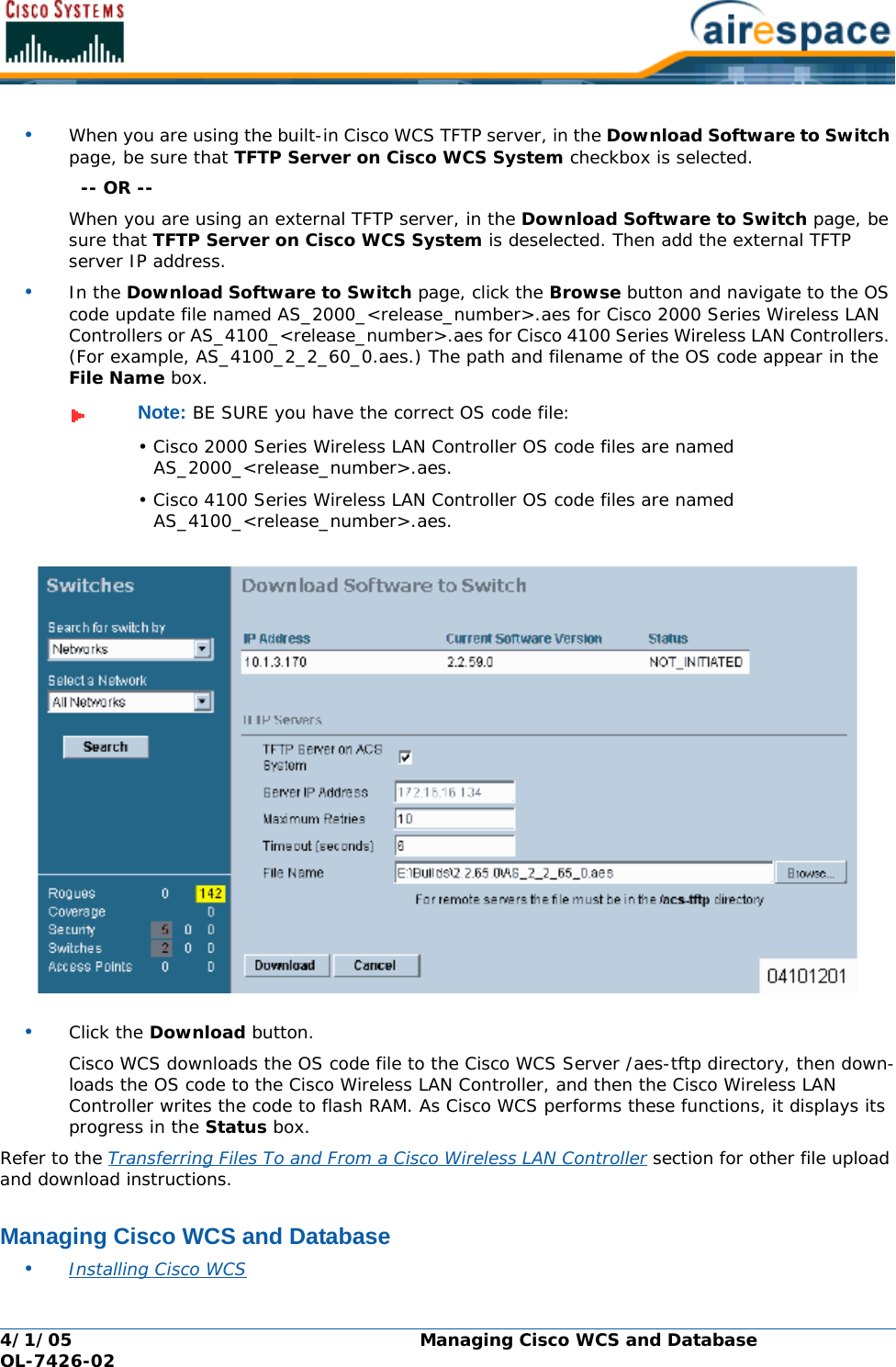
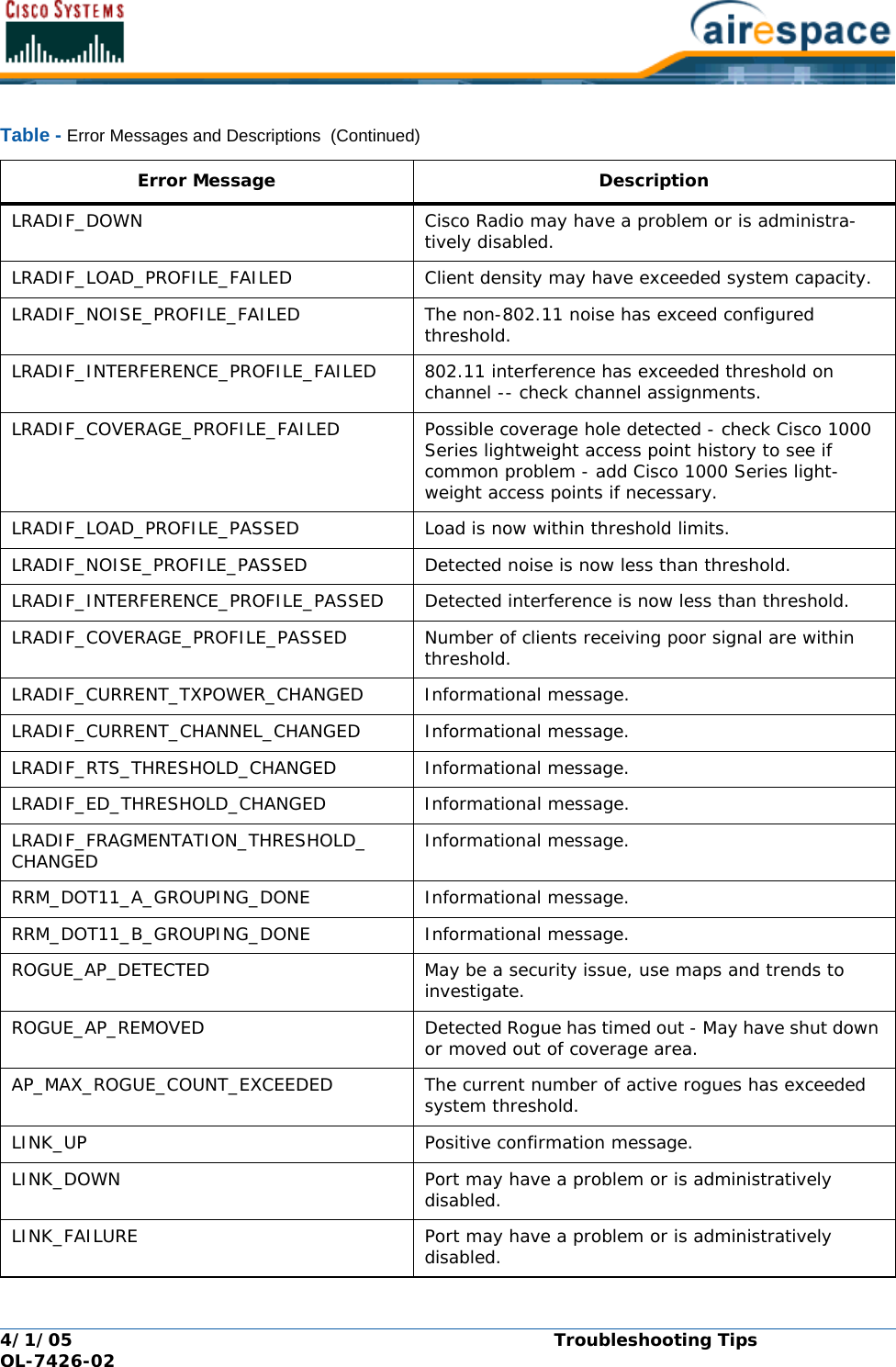
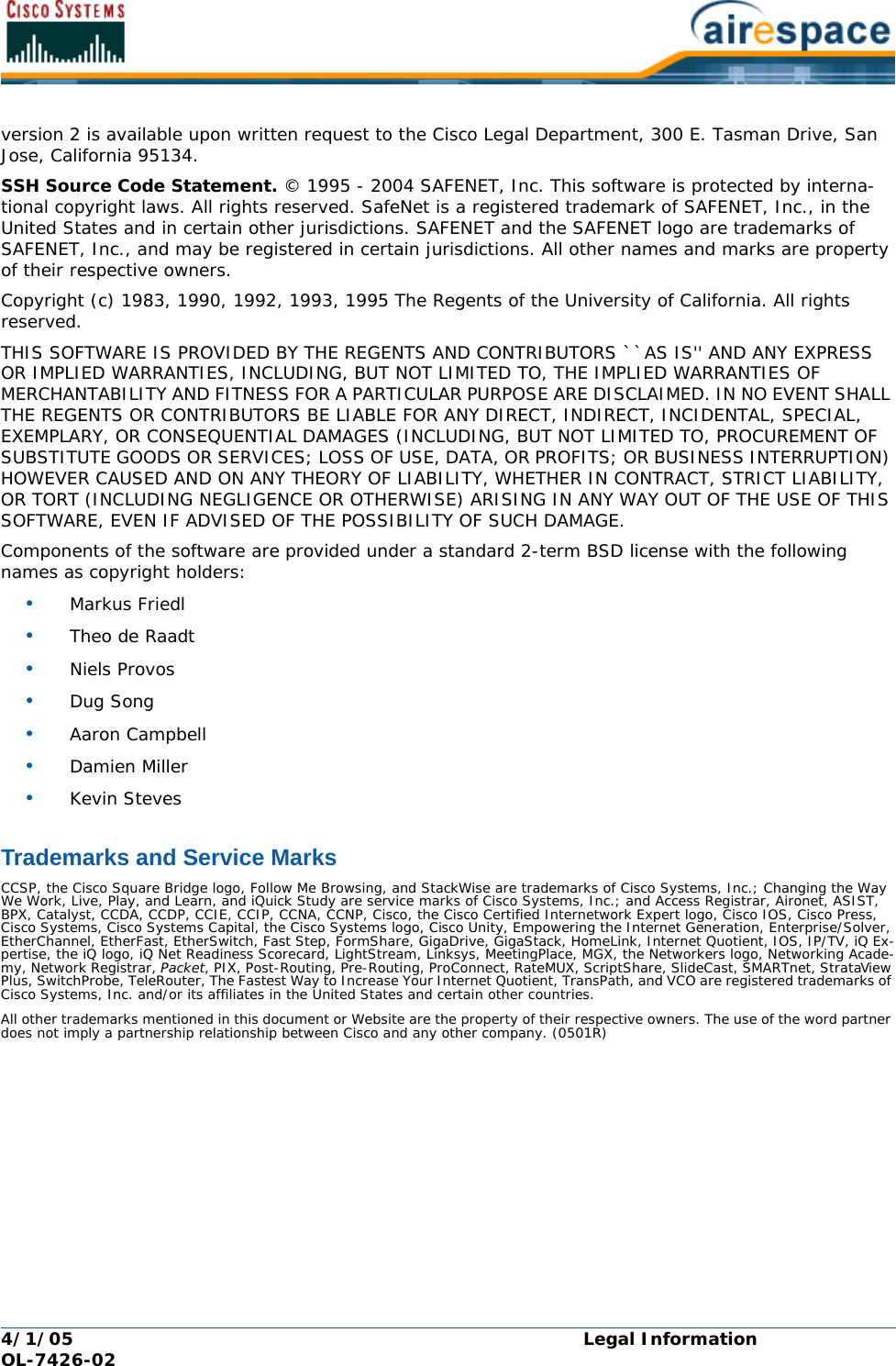
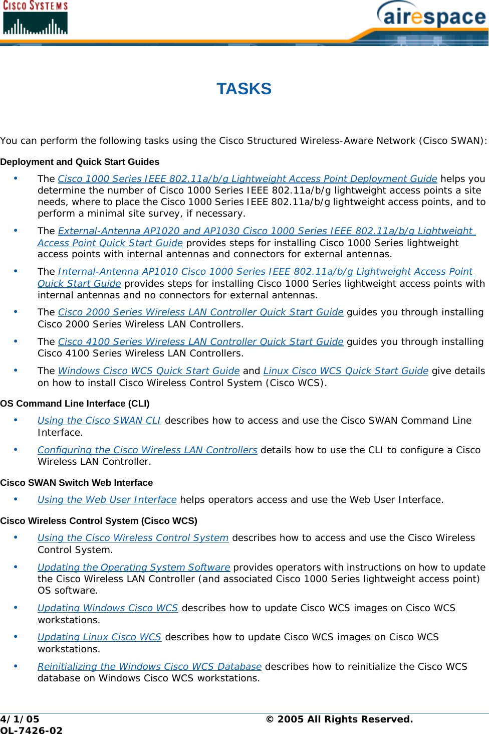
![4/1/05 OL-7426-02Reference [RFC2868] defines RADIUS tunnel attributes used for authentication and authorization, and [RFC2867] defines tunnel attributes used for accounting. Where the IEEE 802.1X Authenticator supports tunneling, a compulsory tunnel may be set up for the Supplicant as a result of the authentication.In particular, it may be desirable to allow a port to be placed into a particular Virtual LAN (VLAN), defined in [IEEE8021Q], based on the result of the authentication. This can be used, for example, to allow a wireless host to remain on the same VLAN as it moves within a campus network.The RADIUS server typically indicates the desired VLAN by including tunnel attributes within the Access-Accept. However, the IEEE 802.1X Authenticator may also provide a hint as to the VLAN to be assigned to the Supplicant by including Tunnel attributes within the Access- Request.For use in VLAN assignment, the following tunnel attributes are used:•Tunnel-Type=VLAN (13)•Tunnel-Medium-Type=802•Tunnel-Private-Group-ID=VLANIDNote that the VLANID is 12-bits, taking a value between 1 and 4094, inclusive. Since the Tunnel-Private-Group-ID is of type String as defined in [RFC2868], for use with IEEE 802.1X, the VLANID integer value is encoded as a string.When Tunnel attributes are sent, it is necessary to fill in the Tag field. As noted in [RFC2868], section 3.1:•The Tag field is one octet in length and is intended to provide a means of grouping attributes in the same packet which refer to the same tunnel. Valid values for this field are 0x01 through 0x1F, inclusive. If the Tag field is unused, it MUST be zero (0x00).•For use with Tunnel-Client-Endpoint, Tunnel-Server-Endpoint, Tunnel-Private-Group-ID, Tunnel-Assignment-ID, Tunnel-Client-Auth-ID or Tunnel-Server-Auth-ID attributes (but not Tunnel-Type, Tunnel-Medium-Type, Tunnel-Password, or Tunnel-Preference), a tag field of greater than 0x1F is interpreted as the first octet of the following field.•Unless alternative tunnel types are provided, (e.g. for IEEE 802.1X Authenticators that may support tunneling but not VLANs), it is only necessary for tunnel attributes to specify a single tunnel. As a result, where it is only desired to specify the VLANID, the tag field SHOULD be set to zero (0x00) in all tunnel attributes. Where alternative tunnel types are to be provided, tag values between 0x01 and 0x1F SHOULD be chosen.](https://usermanual.wiki/Cisco-Systems/102057/User-Guide-566510-Page-106.png)
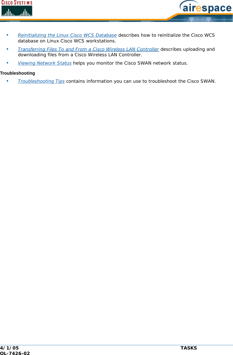
![4/1/05 Viewing Network Status OL-7426-02•Type ‘exit’ to go down a level.•Enter <CTRL-Z> to return to the root level.•From the root level, you can enter the whole command name. For instance, you can enter:>config prompt “Ent1” to change the system prompt to Ent1 >.•To save your changes from active working RAM to non-volatile RAM (NVRAM) so they are retained upon reboot, use the save config command at the CLI root level.•To reset the Cisco Wireless LAN Controller without logging out, use the reset system command at the root level of the CLI tree structure.•When you are done using the CLI console, navigate to the root level and enter logout. You will be prompted to save any changes you have made from the active working RAM to the non-volatile RAM (NVRAM).Viewing Network StatusViewing Network StatusUse the following Command Line Interface commands to view the status of the network controlled by an Cisco Wireless LAN Controllers.•Use the show client commands to display client information for each Cisco 1000 Series light-weight access point 802.11a and 802.11b/g RF coverage area, to display detailed information for a client connected through a particular Cisco 1000 Series lightweight access point, and display a summary of clients connected through the Cisco SWAN:>show client ap [802.11a/802.11b] <Cisco 1000 Series lightweight access point> >show client detail <MAC addr> >show client summaryIf you need to, use the config client deauthenticate command to deauthenticate an indi-vidual <MAC address>.•Use the show rogue-ap summary and show rogue-ap detail commands to discover Rogue APs on the subnet. If necessary, use the config rogue-ap acknowledged, config rogue-ap alert, and config rogue-ap known commands to mark the Rogue APs in the Cisco SWAN database.•In general, use the show commands to view the Cisco SWAN status.•To test a link to a MAC address, use the linktest command at the CLI root level. Note that linktest does not work for IPSec links and does not work from Cisco 1000 Series IEEE 802.11a/b/g lightweight access points.•To ping an IP Address, use the ping command at the CLI root level.Continue with Using the Cisco SWAN CLI.](https://usermanual.wiki/Cisco-Systems/102057/User-Guide-566510-Page-113.png)
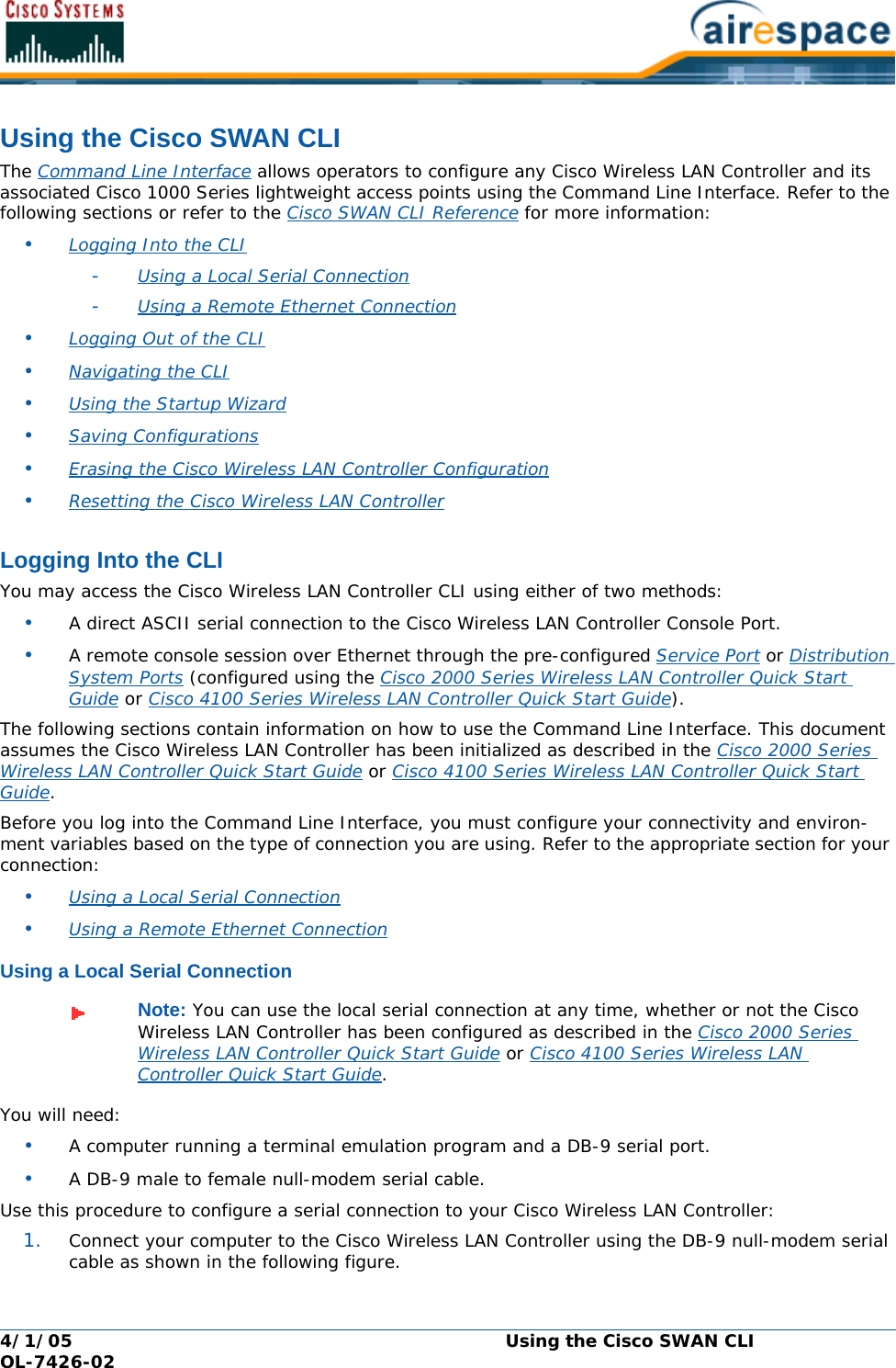
![4/1/05 Configuring Cisco Wireless LAN Controller Interfaces OL-7426-02•Be sure these protocols are configured to agree with your wireless network plan and to comply with the Country Code entered in the previous step using the following commands:>config 802.11a enable network >config 802.11a disable network >config 802.11b enable network >config 802.11b disable network•Use the show sysinfo command to verify that the Cisco Wireless LAN Controller has stored your input. Continue with the next parameter.Users and PasswordsUsers and PasswordsAfter you have configured other system parameters, you are urged to change the username and password so unauthorized personnel cannot easily log into the Cisco SWAN. •Use the show mgmtuser command to view the current management usernames.•Use the following commands to add new usernames and add or change passwords:>config mgmtuser add <username> <password> [read-write/read-only] >config mgmtuser password <username> <new password>where <username>, <password> and <new password> = Any ASCII character string, up to 24 characters, case sensitive, with no spaces. •Use the show mgmtuser command to verify that your users have been accepted by the system. Continue with Configuring Cisco Wireless LAN Controller Interfaces.Configuring Cisco Wireless LAN Controller InterfacesConfiguring Cisco Wireless LAN Controller InterfacesAs described in the Distribution System Ports section, the Cisco 2000 Series Wireless LAN Controller has four independent physical ports, and the Cisco 4100 Series Wireless LAN Controller has two redundant physical ports. This means that the Cisco 2000 Series Wireless LAN Controller can connect to up to four separate subnets, and that the Cisco 4100 Series Wireless LAN Controller can physically connect to one subnet.Each of the physical ports can have multiple Interfaces applied to it:•The Management Interface controls communications with network equipment for all physical ports in all cases. When the Cisco SWAN is operated in Layer 2 Mode (see Layer 2 and Layer 3 LWAPP Operation), the Management Interface also controls communications between the Cisco Wireless LAN Controller and Cisco 1000 Series IEEE 802.11a/b/g Lightweight Access Points.When the Cisco SWAN is operated in Layer 3 Mode, the Management Interface no longer controls communications between the Cisco Wireless LAN Controllers and Cisco 1000 Series lightweight access points. •When the Cisco SWAN is operated in Layer 3 Mode (see Layer 2 and Layer 3 LWAPP Operation), the AP-Manager Interface controls all communications between the Cisco Wireless LAN Controller and Cisco 1000 Series IEEE 802.11a/b/g Lightweight Access Points.•Each physical port can also have between one and 512 Operator-Defined Interfaces, also known as VLAN Interfaces, assigned to it. Each Operator-Defined Interface is individually configured, and allows separate communication streams to exist on any or all of the physical port(s).•The Virtual Interface controls Layer 3 Security and Mobility manager communications for Cisco Wireless LAN Controllers for all physical Ports. It also maintains the DNS Gateway hostname used by Layer 3 Security and Mobility managers to verify the source of certificates when Layer 3 Web Authorization is enabled.](https://usermanual.wiki/Cisco-Systems/102057/User-Guide-566510-Page-117.png)
![4/1/05 Configuring Cisco Wireless LAN Controller Interfaces OL-7426-02•Note that the Cisco 4100 Series Wireless LAN Controller also has a Service-Port Interface, but that Interface can only be applied to the front-panel Service Port.If you have not already done so, you must decide which physical port(s) you want to use, and then create and assign the following:•Verifying and Changing the Management Interface•Creating and Assigning the AP-Manager Interface•Creating, Assigning and Deleting Operator-Defined Interfaces•Verifying and Changing the Virtual InterfaceContinue with the next section to configure the Distribution System IP Address. Verifying and Changing the Management InterfaceVerifying and Changing the Management InterfaceNormally, the static Management Interface parameters are defined when the Cisco Wireless LAN Controller is initially configured using the Startup Wizard. However, you may want to verify and/or change its parameters:•Use the show interface detailed management command to view the current Management Interface settings. Note that the Management Interface uses the burned-in MAC address.•To change any of the parameters, disable all WLANs. >show wlan summary>config wlan disable <1-16, or 17 for Third-Party APs> (repeat for all enabled WLANs)•And then use the following:>config interface address management <IP addr> <IP netmask> [optional gateway]>config interface vlan management <VLAN ID|’0’ for untagged>>config interface port management <Physical DS Port Number>>config interface dhcp management <IP addr of Primary DHCP server> <IP addr of optional Secondary DHCP server>>config interface acl management <Access Control List Name> (Note)using the values collected from the network planner in Collecting Cisco Wireless LAN Controller Parameters.Use the show interface detailed management command to verify that the Cisco Wireless LAN Controller has correctly stored your inputs. Note that this Interface cannot be deleted. Continue with the next section.Creating and Assigning the AP-Manager InterfaceCreating and Assigning the AP-Manager InterfaceThe static AP-Manager Interface only exists when the Cisco SWAN is operating in LWAPP Layer 3 Mode (see Layer 2 and Layer 3 LWAPP Operation). •Use the show interface summary command to view the current Interfaces.If the Cisco SWAN is operating in Layer 2 Mode, the ap-manager interface will not be listed. Either skip this section and continue with Creating, Assigning and Deleting Operator-Defined Interfaces, or go to Converting a Cisco SWAN from Layer 2 to Layer 3 Mode.Note: If you are applying an Access Control List (ACL) to the Management Interface, you must first configure the ACL using the Creating Access Control Lists section.](https://usermanual.wiki/Cisco-Systems/102057/User-Guide-566510-Page-118.png)
![4/1/05 Configuring Cisco Wireless LAN Controller Interfaces OL-7426-02•Use the show interface detailed ap-manager command to view the current AP-Manager Interface settings.•To change any of the parameters, disable all WLANs. >show wlan summary>config wlan disable <1-16, or 17 for Third-Party APs> (repeat for all enabled WLANs)•And then use the following:>config interface address ap-manager <IP addr> <IP netmask> [optional gateway]>config interface vlan ap-manager <VLAN ID|’0’ for untagged>>config interface port ap-manager <Physical DS Port Number>>config interface dhcp ap-manager <IP addr of Primary DHCP server> <IP addr of optional Secondary DHCP server>>config interface acl ap-manager <Access Control List Name> (Note)using the values collected from the network planner in Collecting Cisco Wireless LAN Controller Parameters.Use the show interface detailed ap-manager command to verify that the Cisco Wireless LAN Controller has correctly stored your inputs. Note that this Interface cannot be deleted. Continue with the next section.Creating, Assigning and Deleting Operator-Defined InterfacesCreating, Assigning and Deleting Operator-Defined InterfacesEach Cisco Wireless LAN Controller can support up to 512 dynamic Operator-Defined Interfaces. Each Operator-Defined Interface controls VLAN and other communications between Cisco Wireless LAN Controllers and all other network devices. Between one and 512 Operator-Defined Interfaces can be assigned to Cisco SWAN WLANs, physical Distribution System Ports, the Layer 2 Management Inter-face, and the Layer 3 AP-Manager Interface.•Use the show interface summary command to view the current Operator-Defined Interfaces. They can be identified by the ‘dynamic’ Interface type.•To view the details of an Operator-Defined Interface, use the show interface detailed <operator-defined interface name> command to view the current Operator-Defined Interface settings.•To change any of the parameters or add another Operator-Defined Interface, disable all WLANs. >show wlan summary>config wlan disable <1-16, or 17 for Third-Party APs> (repeat for all enabled WLANs)Note: If you are applying an Access Control List (ACL) to the Management Interface, you must first configure the ACL using the Creating Access Control Lists section. Note: Operator-Defined Interfaces cannot be assigned to the dedicated Cisco 4100 Series Wireless LAN Controller front-panel Service Port.CAUTION: Operator-Defined Interface names cannot have spaces in them. If an Operator-Defined Interface name contains a space, you may not be able to edit its configuration using the Command Line Interface.](https://usermanual.wiki/Cisco-Systems/102057/User-Guide-566510-Page-119.png)
![4/1/05 Configuring Cisco Wireless LAN Controller Interfaces OL-7426-02•And then use the following:>config interface create <operator-defined interface name> <VLAN ID|’0’ for untagged>>config interface address <operator-defined interface name> <IP addr> <IP netmask> [optional gateway]>config interface vlan <operator-defined interface name> <VLAN ID|’0’ for untagged>>config interface port <operator-defined interface name> <Physical DS Port Number>>config interface dhcp <operator-defined interface name> <IP addr of Primary DHCP server> <IP addr of optional Secondary DHCP server>>config interface acl <operator-defined interface name> <Access Control List Name> (Note)using the values collected from the network planner in Collecting Cisco Wireless LAN Controller Parameters.Use the show interface detailed <operator-defined interface name> and show interface summary commands to verify that the Cisco Wireless LAN Controller has correctly stored your inputs.•To delete an Operator-Defined Interface, use the following command:>config interface delete <operator-defined interface name>Continue with the next section.Verifying and Changing the Virtual InterfaceVerifying and Changing the Virtual InterfaceThe static Virtual Interface controls Layer 3 Security and Mobility manager communications for Cisco Wireless LAN Controllers, and it maintains the DNS Gateway hostname used by Layer 3 Security and Mobility managers to verify the source of certificates when Layer 3 Web Authorization is enabled.•Use the show interface detailed virtual command to view the current AP-Manager Interface settings.•To change any of the parameters, disable all WLANs. >show wlan summary>config wlan disable <1-16, or 17 for Third-Party APs> (repeat for all enabled WLANs)•And then use the following:>config interface address virtual <IP addr> where <IP addr> is any fictitious, unassigned, unused Gateway IP Address.>config interface hostname virtual <DNS Host Name>using the values collected from the network planner in Collecting Cisco Wireless LAN Controller Parameters.Note: If you are applying an Access Control List (ACL) to the Operator-Defined Inter-face, you must first configure the ACL using the Creating Access Control Lists section. Note: If you change any of the Virtual Interface settings, reset the Cisco Wireless LAN Controller and save the configuration as described in Resetting the Cisco Wireless LAN Controller.](https://usermanual.wiki/Cisco-Systems/102057/User-Guide-566510-Page-120.png)
![4/1/05 Configuring Cisco Wireless LAN Controller Interfaces OL-7426-02Use the show interface detailed virtual command to verify that the Cisco Wireless LAN Controller has correctly stored your inputs. Note that this Interface cannot be deleted. Continue with the next section.Enabling Web and Secure Web ModesEnabling Web and Secure Web Modes•Use the following commands to enable (default) or disable the Distribution System port as a Web port and/or a Secure Web port:>config network webmode [enable/disable]>config network secureweb [enable/disable]Use the show network command to verify that your inputs were accepted. Continue with the next parameter.Configuring Spanning Tree ProtocolConfiguring Spanning Tree ProtocolSpanning Tree Protocol is initially disabled for the Distribution System (network) ports. You can enable STP on the Cisco Wireless LAN Controller for all physical ports using the following commands. If you are not configuring Spanning Tree Protocol at this time, skip this section.•Use the show spanningtree port and show spanningtree switch commands to view the current STP status.•Disable STP on the Cisco Wireless LAN Controller by entering: >config spanningtree switch mode disableThis causes the Cisco Wireless LAN Controller to disable support for STP on all ports.•Configure the STP port administrative mode on the desired ports using one of the following commands:>config spanningtree port mode 802.1d [<port number>/all] (default) >config spanningtree port mode fast [<port number>/all] >config spanningtree port mode off <[<port number>/all]where <port number> = 1 through 13 or 1 through 25, and all = all ports.•Configure STP port path cost on the STP ports using one of the following commands:>config spanningtree port pathcost <1-65535> [<port number>/all] >config spanningtree port mode pathcost auto [<port number>/all] (default)where <1-65535> = Path cost supplied by the network planner, and auto = allow the STP algo-rithm to automatically assign the path cost (default). •Configure port priority on the STP ports using the following command:>config spanningtree port priority <0-255> <port number>where <0-255> = STP priority for this port (default priority = 128). •If required, configure the Cisco Wireless LAN Controller STP bridge priority using the following command:>config spanningtree switch bridgepriority <0-65535>where <0-65535> = STP bridge priority for this Cisco Wireless LAN Controller (default priority = 32768). •If required, configure the Cisco Wireless LAN Controller STP forward delay using the following command:Note: STP must be disabled before the STP parameters can be changed; leave STP disabled until you have finished configuring all associated parameters.](https://usermanual.wiki/Cisco-Systems/102057/User-Guide-566510-Page-121.png)
![4/1/05 Local MAC Filter OL-7426-02Disable TimeoutDisable TimeoutEach WLAN can have a variable timeout for excluded, or disabled clients. Clients who fail to authenti-cate three times when attempting to associate are automatically excluded, or disabled, from further association attempts. After the exclusion timeout period expires, the client is allowed to retry authenti-cation until it associates or fails authentication and is excluded again. •Use the show wlan command to check the current WLAN Disable (Excluded) Timeout. •If necessary, use the following command to change the Disable (Excluded) Timeout:>config wlan blacklist <WLAN id> <timeout>where <WLAN id> = 1 through 16, and <timeout> = 1 to 65535 seconds, 0 to add to the Exclusion List (formerly blacklist) permanently until the operator manually removes the exclusion.•Use the show wlan command to verify the current WLAN Disable (Excluded) Timeout. VLANsVLANs•Use the show wlan command to verify VLAN assignment status. •To assign a VLAN to a WLAN, use the following command:>config wlan vlan <wlan id> [<default>/<untagged>/<VLAN ID> <IP Address> <VLAN Netmask> <VLAN Gateway>]where <WLAN id> = 1 through 16, <default> = use the VLAN configured on the network port, <untagged> = use VLAN 0, <VLAN id> = 1 through 4095, <IP Address> = the VLAN IP Address on the Cisco Wireless LAN Controller, <VLAN Netmask> = VLAN local IP netmask, and <VLAN Gateway> = VLAN local IP gateway. •To remove a VLAN assignment from a WLAN, use the following command:>config wlan vlan <WLAN id> untaggedwhere <WLAN id> = 1 through 16. •Use the show wlan <wlan id> command to verify that you have correctly assigned a VLAN to the WLAN. Layer 2 SecurityLayer 2 SecurityDynamic 802.1X Keys and AuthorizationDynamic 802.1X Keys and AuthorizationCisco Wireless LAN Controllers can control 802.1X dynamic keys using EAP (extensible authentication protocol) across Cisco 1000 Series lightweight access points, and supports 802.1X dynamic key settings for the Cisco 1000 Series lightweight access point WLAN(s).•Use the show wlan <wlan id> command to check the security settings of each WLAN. The default for new WLANs is 802.1X with dynamic keys enabled. If you want to keep a robust Layer 2 policy, leave 802.1X on.•If you want to change the 802.1X configuration, use the following commands:>config wlan security 802.1X [enable/disable] <wlan id>where <WLAN id> = 1 through 16. Note: WLANs are created in disabled mode; leave them disabled until you have finished configuring them.Note: WLANs are created in disabled mode; leave them disabled until you have finished configuring them.](https://usermanual.wiki/Cisco-Systems/102057/User-Guide-566510-Page-124.png)
![4/1/05 Local MAC Filter OL-7426-02•If you want to change the 802.1X encryption for an Cisco 1000 Series lightweight access point WLAN (not a Third-Party WLAN), use the following command:>config wlan security 802.1X encryption <wlan id> [40/104/128]where <WLAN id> = 1 through 16, and [40/104/128] = 40/64, 104/128 (default) or 128/152 encryption bits (default = 104/128). WEP KeysWEP KeysCisco Wireless LAN Controllers can only control WEP keys across Cisco 1000 Series lightweight access points.•Use the show wlan <wlan id> command to check the security settings of each WLAN. The default is 802.1X with dynamic keys enabled. •If you want to configure the less-robust WEP (Wired Equivalent Privacy) authorization policy, turn 802.1X off:>config wlan security 802.1X disable <wlan id>where <wlan id> = 1 through 16. •Then configure 40/64, 104/128 or 128/152 bit WEP keys on 802.1X disabled WLANs using the following command:>config wlan security static-wep-key encryption <wlan id> [40/104/128] [hex/ascii] <key> <key-index>where:-<wlan id> = 1 through 16; -[hex/ascii] = key character format; -<key> = Ten hexadecimal digits (any combination of 0-9, a-f, or A-F), or five printable ASCII characters for 40-bit/64-bit WEP keys, 26 hexadecimal or 13 ASCII characters for 104-bit/128-bit keys, or 32 hexadecimal or 16 ASCII characters for 128-bit/152-bit keys; and -<key-index> = 1 through 4. Dynamic WPA Keys and EncryptionDynamic WPA Keys and EncryptionCisco Wireless LAN Controllers can only control WPA (Wi-Fi Protected Access) authorization policy across Cisco 1000 Series lightweight access points.•Use the show wlan <wlan id> command to check the security settings of each WLAN. The default is 802.1X with dynamic keys enabled. •If you want to configure the more-robust WPA authorization policy, turn 802.1X off:>config wlan security 802.1X disable <wlan id> where <wlan id> = 1 through 16. •Then configure authorization and dynamic key exchange on 802.1X disabled WLANs using the following commands:>config wlan security wpa enable <wlan id> >config wlan security wpa encryption aes-ocb <wlan id> Note: One unique WEP Key Index can be applied to each WLAN. Because there are only four <key-index> numbers, only four WLANs can be configured for Static WEP Layer 2 encryption. Also note that some legacy clients can only access Key Index 1 through 3 but cannot access Key Index 4.](https://usermanual.wiki/Cisco-Systems/102057/User-Guide-566510-Page-125.png)
![4/1/05 Local MAC Filter OL-7426-02>config wlan security wpa encryption tkip <wlan id> >config wlan security wpa encryption wep <wlan id> [40/104/128]where <wlan id> = 1 through 16, and [40/104/128] = 40/64, 104/128, or 128/156 encryption bits (default = 104). •Use the show wlan command to verify that you have WPA enabled. Layer 3 SecurityLayer 3 SecurityIPSecIPSecIPSec (Internet Protocol Security) supports many Layer 3 security protocols. •Use the show wlan command to show the current IPSec configuration.•Use the following command to enable IPSec on a WLAN:>config wlan security ipsec [enable/disable] <WLAN id>where <WLAN id> = 1 through 16. •Use the show wlan command to verify that you have IPSec enabled. IPSec AuthenticationIPSec AuthenticationIPSec uses hmac-sha-1 authentication as the default for encrypting WLAN data, but can also use hmac-md5, or no authentication. •Use the show wlan command to view the current IPSec authentication protocol.•Use the following command to configure the IPSec IP authentication:>config wlan security ipsec authentication [hmac-md5/hmac-sha-1/none] <WLAN id>where <WLAN id> = 1 through 16. •Use the show wlan command to verify that you have correctly set the IPSec authentication.IPSec EncryptionIIPSec EncryptionIPSec uses 3DES encryption as the default for encrypting WLAN data, but can also use AES, DES, or no encryption. •Use the show wlan command to view the current IPSec encryption.•Use the following command to configure the IPSec encryption:>config wlan security ipsec encryption [3des/aes/des/none] <WLAN id>where aes= AES-CBC, and where <WLAN id> = 1 through 16. •Use the show wlan command to verify that you have correctly set the IPSec encryption.Note: WLANs are created in disabled mode; leave them disabled until you have finished configuring them.Note: Using Layer 3 security requires that the Cisco 4100 Series Wireless LAN Controller be equipped with a VPN/Enhanced Security Module (Crypto Module). The ESM plugs into the rear of the Cisco 4100 Series Wireless LAN Controller, and provides the extra processing power needed for processor-intensive security algorithms.](https://usermanual.wiki/Cisco-Systems/102057/User-Guide-566510-Page-126.png)
![4/1/05 Local MAC Filter OL-7426-02IKE AuthenticationIKE AuthenticationIPSec IKE (Internet Key Exchange) uses pre-shared key exchanges, x.509 (RSA Signatures) certifi-cates, and XAuth-psk for authentication. •Use the show wlan command to see if IPSec IKE is enabled.•Use the following commands to configure IKE authentication on a WLAN with IPSec enabled:>config wlan security ipsec ike authentication certificates <wlan id> >config wlan security ipsec ike authentication xauth-psk <wlan id> <key>>config wlan security ipsec ike authentication pre-shared-key <wlan id> <key>where <wlan id> = 1 through 16, certificates = RSA signatures, xauth-psk = XAuth pre-shared key, and <key> = Preshared Key (Eight to 255 ASCII characters, case sensitive). •Use the show wlan command to verify that you have IPSec IKE enabled. IKE Diffie-Hellman GroupIKE Diffie-Hellman GroupIPSec IKE uses Diffie-Hellman groups to block easily decrypted keys. •Use the show wlan command to verify whether or not the Cisco Wireless LAN Controller has IPSec IKE DH Groups properly set. •Use the following command to configure the IKE Diffie-Hellman group on a WLAN with IPSec enabled:>config wlan security ipsec ike DH-Group <WLAN id> <group-id>where <WLAN id> = 1 through 16; <group-id> = group-1, group-2 (default), or group-5. •Use the show wlan command to verify that the Cisco Wireless LAN Controller has IPSec IKE DH Groups properly set. IKE Phase 1 Aggressive and Main ModesIKE Phase 1 Aggressive and Main ModesIPSec IKE uses the Phase 1 Aggressive (faster) or Main (more secure) mode to set up encryption between clients and the Cisco Wireless LAN Controller. •Use the show wlan command to see if the Cisco Wireless LAN Controller has IPSec IKE Aggressive mode enabled. •If necessary, use the following command to configure the IKE Aggressive or Main mode on a WLAN with IPSec enabled:>config wlan security ipsec ike phase1 [aggressive/main] <WLAN id>where <WLAN id> = 1 through 16. •Use the show wlan command to verify that you have IPSec IKE Aggressive or Main mode enabled. IKE Lifetime TimeoutIKE Lifetime TimeoutIPSec IKE uses its timeout to limit the time that an IKE key is active. •Use the show wlan command to see the current IPSec IKE lifetime timeout. •Use the following command to configure the IKE lifetime on a WLAN with IPSec enabled:>config wlan security ipsec ike lifetime <WLAN id> <seconds>where <WLAN id> = 1 through 16, and <seconds> = 1800 through 345600 seconds (default = 28800 seconds). •Use the show wlan command to verify that you have IPSec IKE timeout properly set.](https://usermanual.wiki/Cisco-Systems/102057/User-Guide-566510-Page-127.png)
![4/1/05 Local MAC Filter OL-7426-02IPSec PassthroughIPSec PassthroughIPSec IKE uses IPSec Passthrough to allow IPSec-capable clients to communicate directly with other IPSec equipment. IPSec Passthrough is also known as VPN Passthrough.•Use the show wlan command to see the current IPSec passthrough status. •Use the following command to configure IKE passthrough for a WLAN:>config wlan security passthru [enable/disable] <WLAN id> [gateway]where <WLAN id> = 1 through 16, and [gateway] = IP Address of IPSec (VPN) passthrough gateway. •Use the show wlan command to verify that you have IPSec passthrough properly set. Web Based AuthenticationWeb Based AuthenticationWLANs can use Web Authentication if IPSec is not enabled on the Cisco Wireless LAN Controller. Web Authentication is simple to set up and use, and can be used with SSL to improve the overall security of the wireless LAN.•Use the show wlan command to see the current Web Authentication status. •Use the following command to configure Web Authentication for a WLAN:>config wlan security web [enable/disable] <WLAN id>where <WLAN id> = 1 through 16.•Use the show wlan command to verify that you have Web Authentication properly set. Local NetuserLocal NetuserCisco Wireless LAN Controllers have built-in network client authentication capability, similar to that provided by a RADIUS authentication server. •Use the show netuser command to see if the Cisco Wireless LAN Controller has network client names assigned to WLANs. •If required, use the following commands to assign a network client name and password to a particular WLAN, delete a network client, assign a network client password, and assign a network client name to a WLAN without a password:>config netuser add <username> <password> <WLAN id>>config netuser delete <username>>config netuser password <username> <password>>config netuser wlan-id <username> <WLAN id>where <WLAN id> = 1 through 16. •Use the show netuser command to verify that you have net usernames assigned to WLANs. Quality of ServiceQuality of ServiceCisco SWAN WLANs support four levels of QoS: Platinum/Voice, Gold/Video, Silver/Best Effort (default) and Bronze/Background. Network administrators can choose to assign the voice traffic WLAN to use Note: WLANs are created in disabled mode; leave them disabled until you have finished configuring them.Note: WLANs are created in disabled mode; leave them disabled until you have finished configuring them.](https://usermanual.wiki/Cisco-Systems/102057/User-Guide-566510-Page-128.png)
![4/1/05 Configuring Controller Mobility Groups OL-7426-02Platinum QoS, assign the low-bandwidth WLAN to use Bronze QoS, and assign all other traffic between the remaining QoS levels. •Use the show wlan command to verify that you have QoS properly set for each WLAN. •If required, use the following command to configure QoS for each WLAN:>config wlan qos <WLAN id> [bronze/silver/gold/platinum]where <WLAN id> = 1 through 16. •Use the show wlan command to verify that you have QoS properly set for each WLAN. Activating WLANsActivating WLANsAfter you have completely configured your WLAN settings, activate the WLAN using the config wlan enable command.Continue with Configuring Controller Mobility Groups.Configuring Controller Mobility GroupsConfiguring Controller Mobility GroupsAll Cisco Wireless LAN Controllers that can communicate with each other through their Distribution System (network) ports can automatically discover each other and form themselves into groups. Once they are grouped, the Cisco SWAN Radio Resource Management (RRM) function maximizes its inter-Cisco Wireless LAN Controller processing efficiency and mobility processing, described in the Client Roaming section in the Product Guide.Cisco Wireless LAN Controller group discovery is automatically enabled when two or more members are assigned to the same Controller Mobility Group name. Note that this feature must be enabled on each Cisco Wireless LAN Controller to be included in the discovery process.•Use the show mobility summary command to verify the current Cisco Wireless LAN Controller mobility settings.•To give a Controller Mobility Group a name, use the following command:>config mobility group name <group_name>where <group_name> = Any ASCII character string, up to 31 characters, case sensitive, with no spaces. •To manually add or delete members to a Controller Mobility Group, use the following commands:>config mobility group member add <mac-address> <IP addr> >config mobility group member delete <mac-address> <IP addr>where <mac-address> is the MAC address and where <IP addr> is the IP Address of the group member to be added or deleted.Use the show mobility summary commands to verify that the Cisco Wireless LAN Controller mobility is set up correctly. Continue with Configuring RADIUS.Configuring RADIUSConfiguring RADIUS•When your Cisco SWAN is to use an external RADIUS server for accounting and/or authenti-cation, set up the links using the following commands. If you are not configuring RADIUS links at this time, continue with Configuring SNMP.>config radius acct <address> >config radius acct <port> >config radius acct <secret> >config radius acct [disable/enable]](https://usermanual.wiki/Cisco-Systems/102057/User-Guide-566510-Page-129.png)
![4/1/05 Configuring SNMP OL-7426-02>config radius auth <address> >config radius auth <port> >config radius auth <secret> >config radius auth [disable/enable]where <address> = server name or IP Address, <port> = UDP port number, <secret> = the RADIUS server's secret.When you have completed these configurations, use the show radius acct statistics, show radius auth statistics and show radius summary commands to verify that the RADIUS links are correctly configured. Continue with Configuring SNMP.Configuring SNMPConfiguring SNMP•When your Cisco SWAN is to send SNMP protocol to the Cisco Wireless Control System or any other SNMP manager, configure the SNMP environment using the following commands. If you are not configuring SNMP traps at this time, continue with Configuring Other Ports and Parameters.>config snmp community accessmode <ro/rw> <name> >config snmp community create <name> >config snmp community delete <name> >config snmp community ipaddr <ipaddr> <ipmask> <name> >config snmp community mode [enable/disable]>config snmp trapreceiver create <name> <ipaddr> >config snmp trapreceiver delete <name> >config snmp trapreceiver ipaddr <old ipaddr> <name> <new ipaddr> >config snmp trapreceiver mode [enable/disable]>config snmp syscontact <syscontact name>>config snmp syslocation <syslocation name>where <ro/rw> = read only/read-write, <name> = SNMP community name, <ipaddr> = SNMP community IP Address, <ipmask> = SNMP community IP mask, <old ipaddr> = old SNMP IP Address, <new ipaddr> = new SNMP IP Address, <syscontact name> = system contact, up to 31 alphanumeric characters, <syslocation name> = system location, up to 31 alphanumeric characters.When you have completed these configurations, use the show snmpcommunity and show snmptrap commands to verify that the SNMP traps and communities are correctly configured. Also use the show trapflags command to see the enabled and disabled trapflags. If necessary, use the config trapflags commands to enable and disable any or all trapflags.Continue with Configuring Other Ports and Parameters.Configuring Other Ports and ParametersConfiguring Other Ports and ParametersUse the following sections to configure the remaining Cisco Wireless LAN Controller ports and parameters:•Service Port •Radio Resource Management (RRM) •Serial (CLI Console) Port •802.3x Flow Control •System Logging](https://usermanual.wiki/Cisco-Systems/102057/User-Guide-566510-Page-130.png)