Cisco Systems 102057 Air-AP1000 Series Dual Band 2.4/5 GHz Access Point User Manual Product Guide SANS
Cisco Systems Inc Air-AP1000 Series Dual Band 2.4/5 GHz Access Point Product Guide SANS
User Manual

4/1/05 © 2005 All Rights Reserved.
OL-7426-02
Welcome to the Product Guide!Product Guide
Cisco SWAN 2.2: Last Updated April 1, 2005
The Product Guide describes the Cisco SWAN products.
Refer to the OVERVIEWS section to see a big picture view of Cisco SWAN products and
features.
See the SOLUTIONS section to look through real-world network and application-
specific solutions to real-world problems.
Go to the TASKS section to find detailed instructions on how to install, configure, use,
and troubleshoot Cisco SWAN products and supported 802.11 networks.
Visit the REFERENCES section to find technical information, such as the Glossary,
Supported Country Codes, CLI Reference, Web User Interface Online Help files, Cisco
WCS Online Help files, Cisco 1000 Series Lightweight Access Point Deployment Guide,
Hardware and Software Quick Start Guides, and pointers to the current Release Notes.
FCC Statements for Cisco 4100 Series Wireless LAN Controllers
FCC Statements for Cisco 2000 Series Wireless LAN Controllers
FCC Statements for Cisco 1000 Series Lightweight Access Points
Industry Canada Required User Information for Cisco 1000 Series Lightweight Access Points
Legal Information
Obtaining Documentation
Documentation Feedback
Cisco Product Security Overview
Obtaining Technical Assistance


4/1/05 Legal Information
OL-7426-02
Legal InformationLegal Information
This section includes the following legal information:
•Products
•End User License Agreement
•Limited Warranty
•General Terms Applicable to the Limited Warranty Statement and End User License Agreement
•Additional Open Source Terms
•Trademarks and Service Marks
The following describes the Cisco Systems, Inc. standard Product Warranty for End Customers.
ProductsProducts
•Cisco 2000 Series Wireless LAN Controllers
•Cisco 4100 Series Wireless LAN Controllers
•Cisco 1000 Series IEEE 802.11a/b/g lightweight access points
End User License AgreementEnd User License Agreement
IMPORTANT: PLEASE READ THIS END USER LICENSE AGREEMENT CAREFULLY. DOWN-
LOADING, INSTALLING OR USING CISCO OR CISCO-SUPPLIED SOFTWARE CONSTITUTES
ACCEPTANCE OF THIS AGREEMENT.
CISCO IS WILLING TO LICENSE THE SOFTWARE TO YOU ONLY UPON THE CONDITION THAT YOU
ACCEPT ALL OF THE TERMS CONTAINED IN THIS LICENSE AGREEMENT. BY DOWNLOADING OR
INSTALLING THE SOFTWARE, OR USING THE EQUIPMENT THAT CONTAINS THIS SOFTWARE, YOU ARE
BINDING YOURSELF AND THE BUSINESS ENTITY THAT YOU REPRESENT (COLLECTIVELY,
“CUSTOMER”) TO THIS AGREEMENT. IF YOU DO NOT AGREE TO ALL OF THE TERMS OF THIS AGREE-
MENT, THEN CISCO IS UNWILLING TO LICENSE THE SOFTWARE TO YOU AND (A) DO NOT DOWNLOAD,
INSTALL OR USE THE SOFTWARE, AND (B) YOU MAY RETURN THE SOFTWARE FOR A FULL REFUND,
OR, IF THE SOFTWARE IS SUPPLIED AS PART OF ANOTHER PRODUCT, YOU MAY RETURN THE ENTIRE
PRODUCT FOR A FULL REFUND. YOUR RIGHT TO RETURN AND REFUND EXPIRES 30 DAYS AFTER
PURCHASE FROM CISCO OR AN AUTHORIZED CISCO RESELLER, AND APPLIES ONLY IF YOU ARE THE
ORIGINAL END USER PURCHASER.
The following terms of this End User License Agreement (“Agreement”) govern Customer’s access and
use of the Software, except to the extent (a) there is a separate signed agreement between Customer
and Cisco governing Customer’s use of the Software or (b) the Software includes a separate
“click-accept” license agreement as part of the installation and/or download process. To the extent of a
conflict between the provisions of the foregoing documents, the order of precedence shall be (1) the
signed agreement, (2) the click-accept agreement, and (3) this End User License Agreement.
License. Conditioned upon compliance with the terms and conditions of this Agreement, Cisco
Systems, Inc. or its subsidiary licensing the Software instead of Cisco Systems, Inc. (“Cisco”), grants to
Customer a nonexclusive and nontransferable license to use for Customer’s internal business purposes
the Software and the Documentation for which Customer has paid the required license fees. “Documen-
tation” means written information (whether contained in user or technical manuals, training materials,
specifications or otherwise) specifically pertaining to the Software and made available by Cisco with the
Software in any manner (including on CD-ROM, or on-line).
Customer’s license to use the Software shall be limited to, and Customer shall not use the Software in
excess of, a single hardware chassis or card or that number of agent(s), concurrent users, sessions, IP

4/1/05 Legal Information
OL-7426-02
addresses, port(s), seat(s), server(s) or site(s), as set forth in the applicable Purchase Order which has
been accepted by Cisco and for which Customer has paid to Cisco the required license fee.
Unless otherwise expressly provided in the Documentation, Customer shall use the Software solely as
embedded in, for execution on, or (where the applicable documentation permits installation on
non-Cisco equipment) for communication with Cisco equipment owned or leased by Customer and used
for Customer’s internal business purposes. NOTE: For evaluation or beta copies for which Cisco does
not charge a license fee, the above requirement to pay license fees does not apply.
General Limitations. This is a license, not a transfer of title, to the Software and Documentation, and
Cisco retains ownership of all copies of the Software and Documentation. Customer acknowledges that
the Software and Documentation contain trade secrets of Cisco, its suppliers or licensors, including but
not limited to the specific internal design and structure of individual programs and associated interface
information. Accordingly, except as otherwise expressly provided under this Agreement, Customer shall
have no right, and Customer specifically agrees not to:
(i) transfer, assign or sublicense its license rights to any other person or entity, or use the Software
on unauthorized or secondhand Cisco equipment, and Customer acknowledges that any attempted
transfer, assignment, sublicense or use shall be void;
(ii) make error corrections to or otherwise modify or adapt the Software or create derivative works
based upon the Software, or permit third parties to do the same;
(iii) reverse engineer or decompile, decrypt, disassemble or otherwise reduce the Software to
human-readable form, except to the extent otherwise expressly permitted under applicable law
notwithstanding this restriction;
(iv) use or permit the Software to be used to perform services for third parties, whether on a service
bureau or time sharing basis or otherwise, without the express written authorization of Cisco; or
(v) disclose, provide, or otherwise make available trade secrets contained within the Software and
Documentation in any form to any third party without the prior written consent of Cisco. Customer shall
implement reasonable security measures to protect such trade secrets; or
(vi) use the Software to develop any software application intended for resale which employs the
Software.
To the extent required by law, and at Customer's written request, Cisco shall provide Customer with the
interface information needed to achieve interoperability between the Software and another indepen-
dently created program, on payment of Cisco's applicable fee, if any. Customer shall observe strict
obligations of confidentiality with respect to such information and shall use such information in compli-
ance with any applicable terms and conditions upon which Cisco makes such information available.
Customer is granted no implied licenses to any other intellectual property rights other than as specifi-
cally granted herein.
Software, Upgrades and Additional Copies. For purposes of this Agreement, “Software” shall
include (and the terms and conditions of this Agreement shall apply to) computer programs, including
firmware, as provided to Customer by Cisco or an authorized Cisco reseller, and any upgrades,
updates, bug fixes or modified versions thereto (collectively, “Upgrades”) or backup copies of the
Software licensed or provided to Customer by Cisco or an authorized Cisco reseller. NOTWITH-
STANDING ANY OTHER PROVISION OF THIS AGREEMENT: (1) CUSTOMER HAS NO LICENSE OR RIGHT
TO USE ANY ADDITIONAL COPIES OR UPGRADES UNLESS CUSTOMER, AT THE TIME OF ACQUIRING
SUCH COPY OR UPGRADE, ALREADY HOLDS A VALID LICENSE TO THE ORIGINAL SOFTWARE AND HAS
PAID THE APPLICABLE FEE FOR THE UPGRADE OR ADDITIONAL COPIES; (2) USE OF UPGRADES IS
LIMITED TO CISCO EQUIPMENT FOR WHICH CUSTOMER IS THE ORIGINAL END USER PURCHASER OR
LESSEE OR WHO OTHERWISE HOLDS A VALID LICENSE TO USE THE SOFTWARE WHICH IS BEING
UPGRADED; AND (3) THE MAKING AND USE OF ADDITIONAL COPIES IS LIMITED TO NECESSARY
BACKUP PURPOSES ONLY.
Proprietary Notices. Customer agrees to maintain and reproduce all copyright and other proprietary
notices on all copies, in any form, of the Software in the same form and manner that such copyright

4/1/05 Legal Information
OL-7426-02
and other proprietary notices are included on the Software. Except as expressly authorized in this
Agreement, Customer shall not make any copies or duplicates of any Software without the prior written
permission of Cisco.
Open Source Content. Customer acknowledges that the Software contains open source or publicly
available content under separate license and copyright requirements which are located either in an
attachment to this license, the Software README file or the Documentation. Customer agrees to
comply with such separate license and copyright requirements.
Third Party Beneficiaries. Certain Cisco or Cisco affiliate suppliers are intended third party beneficia-
ries of this Agreement. The terms and conditions herein are made expressly for the benefit of and are
enforceable by Cisco’s suppliers; provided, however, that suppliers are not in any contractual relation-
ship with Customer. Cisco’s suppliers include without limitation: (a) Hifn, Inc., a Delaware corporation
with principal offices at 750 University Avenue, Los Gatos, California and (b) Wind River Systems, Inc.,
and its suppliers. Additional suppliers may be provided in subsequent updates of Documentation
supplied to Customer.
Term and Termination. This Agreement and the license granted herein shall remain effective until
terminated. Customer may terminate this Agreement and the license at any time by destroying all
copies of Software and any Documentation. Customer’s rights under this Agreement will terminate
immediately without notice from Cisco if Customer fails to comply with any provision of this Agreement.
Cisco and its suppliers are further entitled to obtain injunctive relief if Customer’s use of the Software is
in violation of any license restrictions. Upon termination, Customer shall destroy all copies of Software
and Documentation in its possession or control. All confidentiality obligations of Customer and all limi-
tations of liability and disclaimers and restrictions of warranty shall survive termination of this
Agreement. In addition, the provisions of the sections titled “U.S. Government End User Purchasers”
and “General Terms Applicable to the Limited Warranty Statement and End User License” shall survive
termination of this Agreement.
Customer Records. Customer grants to Cisco and its independent accountants the right to examine
Customer’s books, records and accounts during Customer’s normal business hours to verify compliance
with this Agreement. In the event such audit discloses non-compliance with this Agreement, Customer
shall promptly pay to Cisco the appropriate license fees, plus the reasonable cost of conducting the
audit.
Export. Software and Documentation, including technical data, may be subject to U.S. export control
laws, including the U.S. Export Administration Act and its associated regulations, and may be subject to
export or import regulations in other countries. Customer agrees to comply strictly with all such regula-
tions and acknowledges that it has the responsibility to obtain licenses to export, re-export, or import
Software and Documentation. Customer’s failure to comply with such restrictions shall constitute a
material breach of the Agreement.
U.S. Government End User Purchasers. The Software and Documentation qualify as “commercial
items,” as that term is defined at Federal Acquisition Regulation (“FAR”) (48 C.F.R.) 2.101, consisting of
“commercial computer software” and “commercial computer software documentation” as such terms
are used in FAR 12.212. Consistent with FAR 12.212 and DoD FAR Supp. 227.7202-1 through
227.7202-4, and notwithstanding any other FAR or other contractual clause to the contrary in any
agreement into which this End User License Agreement may be incorporated, Customer may provide to
Government end user or, if this Agreement is direct, Government end user will acquire, the Software
and Documentation with only those rights set forth in this End User License Agreement. Use of either
the Software or Documentation or both constitutes agreement by the Government that the Software
and Documentation are “commercial computer software” and “commercial computer software docu-
mentation,” and constitutes acceptance of the rights and restrictions herein.
Limited WarrantyLimited Warranty
Hardware for 1000 Series Access Points. Cisco Systems, Inc., or the Cisco Systems, Inc. subsidiary
selling the Product (“Cisco”) warrants that commencing from the date of shipment to Customer (and in

4/1/05 Legal Information
OL-7426-02
case of resale by a Cisco reseller, commencing not more than ninety (90) days after original shipment
by Cisco), and continuing for a period of one (1) year, the Hardware will be free from defects in
material and workmanship under normal use. The date of shipment of a Product by Cisco is set forth on
the packaging material in which the Product is shipped. This limited warranty extends only to the
original user of the Product. Customer's sole and exclusive remedy and the entire liability of Cisco and
its suppliers under this limited warranty will be, at Cisco's or its service center's option, shipment of a
replacement within the warranty period and according to the replacement process described in the
Warranty Card (if any), or if no Warranty Card, as described at www.cisco.com/en/US/products/
prod_warranties_listing.html or a refund of the purchase price if the Hardware is returned to the party
supplying it to Customer, freight and insurance prepaid. Cisco replacement parts used in Hardware
replacement may be new or equivalent to new. Cisco's obligations hereunder are conditioned upon the
return of affected Hardware in accordance with Cisco's or its service center's then-current Return
Material Authorization (RMA) procedures.
Hardware for 4100 Series Wireless LAN Controllers. Cisco Systems, Inc., or the Cisco Systems,
Inc. subsidiary selling the Product (“Cisco”) warrants that commencing from the date of shipment to
Customer (and in case of resale by a Cisco reseller, commencing not more than ninety (90) days after
original shipment by Cisco), and continuing for a period of ninety (90) days, the Hardware will be free
from defects in material and workmanship under normal use. The date of shipment of a Product by
Cisco is set forth on the packaging material in which the Product is shipped. This limited warranty
extends only to the original user of the Product. Customer's sole and exclusive remedy and the entire
liability of Cisco and its suppliers under this limited warranty will be, at Cisco's or its service center's
option, shipment of a replacement within the warranty period and according to the replacement process
described in the Warranty Card (if any), or if no Warranty Card, as described at www.cisco.com/en/US/
products/prod_warranties_listing.html or a refund of the purchase price if the Hardware is returned to
the party supplying it to Customer, freight and insurance prepaid. Cisco replacement parts used in
Hardware replacement may be new or equivalent to new. Cisco's obligations hereunder are conditioned
upon the return of affected Hardware in accordance with Cisco's or its service center's then-current
Return Material Authorization (RMA) procedures.
Software. Cisco warrants that commencing from the date of shipment to Customer (but in case of
resale by an authorized Cisco reseller, commencing not more than ninety (90) days after original
shipment by Cisco), and continuing for a period of the longer of (a) ninety (90) days or (b) the software
warranty period (if any) set forth in the warranty card accompanying the Product (if any): (a) the
media on which the Software is furnished will be free of defects in materials and workmanship under
normal use; and (b) the Software substantially conforms to its published specifications. The date of
shipment of a Product by Cisco is set forth on the packaging material in which the Product is shipped.
Except for the foregoing, the Software is provided AS IS. This limited warranty extends only to the
Customer who is the original licensee. Customer's sole and exclusive remedy and the entire liability of
Cisco and its suppliers and licensors under this limited warranty will be, at Cisco's option, repair,
replacement, or refund of the Software if reported (or, upon request, returned) to Cisco or the party
supplying the Software to Customer. In no event does Cisco warrant that the Software is error free or
that Customer will be able to operate the Software without problems or interruptions. In addition, due
to the continual development of new techniques for intruding upon and attacking networks, Cisco does
not warrant that the Software or any equipment, system or network on which the Software is used will
be free of vulnerability to intrusion or attack.
Restrictions. This warranty does not apply if the Software, Product or any other equipment upon
which the Software is authorized to be used (a) has been altered, except by Cisco or its authorized
representative, (b) has not been installed, operated, repaired, or maintained in accordance with
instructions supplied by Cisco, (c) has been subjected to abnormal physical or electrical stress, misuse,
negligence, or accident; or (d) is licensed, for beta, evaluation, testing or demonstration purposes for
which Cisco does not charge a purchase price or license fee.
Disclaimer of Warranty DISCLAIMER OF WARRANTY
EXCEPT AS SPECIFIED IN THIS WARRANTY, ALL EXPRESS OR IMPLIED CONDITIONS, REPRE-
SENTATIONS, AND WARRANTIES INCLUDING, WITHOUT LIMITATION, ANY IMPLIED

4/1/05 Legal Information
OL-7426-02
WARRANTY OR CONDITION OF MERCHANTABILITY, FITNESS FOR A PARTICULAR PURPOSE,
NON-INFRINGEMENT, SATISFACTORY QUALITY, NON-INTERFERENCE, ACCURACY OF INFOR-
MATIONAL CONTENT, OR ARISING FROM A COURSE OF DEALING, LAW, USAGE, OR TRADE
PRACTICE, ARE HEREBY EXCLUDED TO THE EXTENT ALLOWED BY APPLICABLE LAW AND ARE
EXPRESSLY DISCLAIMED BY CISCO, ITS SUPPLIERS AND LICENSORS. TO THE EXTENT AN
IMPLIED WARRANTY CANNOT BE EXCLUDED, SUCH WARRANTY IS LIMITED IN DURATION
TO THE EXPRESS WARRANTY PERIOD. BECAUSE SOME STATES OR JURISDICTIONS DO NOT
ALLOW LIMITATIONS ON HOW LONG AN IMPLIED WARRANTY LASTS, THE ABOVE LIMITA-
TION MAY NOT APPLY. THIS WARRANTY GIVES CUSTOMER SPECIFIC LEGAL RIGHTS, AND
CUSTOMER MAY ALSO HAVE OTHER RIGHTS WHICH VARY FROM JURISDICTION TO JURIS-
DICTION. This disclaimer and exclusion shall apply even if the express warranty set forth above fails of
its essential purpose.
General Terms Applicable to the Limited Warranty Statement and End User
License AgreementGeneral Terms Applicable to the Limited Warranty Statement and End User License Agreement
Disclaimer of Liabilities. REGARDLESS WHETHER ANY REMEDY SET FORTH HEREIN FAILS OF ITS
ESSENTIAL PURPOSE OR OTHERWISE, IN NO EVENT WILL CISCO OR ITS SUPPLIERS BE LIABLE FOR
ANY LOST REVENUE, PROFIT, OR LOST OR DAMAGED DATA, BUSINESS INTERRUPTION, LOSS OF
CAPITAL, OR FOR SPECIAL, INDIRECT, CONSEQUENTIAL, INCIDENTAL, OR PUNITIVE DAMAGES
HOWEVER CAUSED AND REGARDLESS OF THE THEORY OF LIABILITY OR WHETHER ARISING OUT OF
THE USE OF OR INABILITY TO USE SOFTWARE OR OTHERWISE AND EVEN IF CISCO OR ITS SUPPLIERS
OR LICENSORS HAVE BEEN ADVISED OF THE POSSIBILITY OF SUCH DAMAGES. In no event shall
Cisco's or its suppliers' or licensors’ liability to Customer, whether in contract, tort (including negli-
gence), breach of warranty, or otherwise, exceed the price paid by Customer for the Software that gave
rise to the claim or if the Software is part of another Product, the price paid for such other Product.
BECAUSE SOME STATES OR JURISDICTIONS DO NOT ALLOW LIMITATION OR EXCLUSION OF CONSE-
QUENTIAL OR INCIDENTAL DAMAGES, THE ABOVE LIMITATION MAY NOT APPLY TO YOU.
Customer agrees that the limitations of liability and disclaimers set forth herein will apply regardless of
whether Customer has accepted the Software or any other product or service delivered by Cisco.
Customer acknowledges and agrees that Cisco has set its prices and entered into this Agreement in
reliance upon the disclaimers of warranty and the limitations of liability set forth herein, that the same
reflect an allocation of risk between the parties (including the risk that a contract remedy may fail of its
essential purpose and cause consequential loss), and that the same form an essential basis of the
bargain between the parties.
The Warranty and the End User License shall be governed by and construed in accordance with the laws
of the State of California, without reference to or application of choice of law rules or principles. The
United Nations Convention on the International Sale of Goods shall not apply. If any portion hereof is
found to be void or unenforceable, the remaining provisions of the Agreement shall remain in full force
and effect. Except as expressly provided herein, this Agreement constitutes the entire agreement
between the parties with respect to the license of the Software and Documentation and supersedes any
conflicting or additional terms contained in any purchase order or elsewhere, all of which terms are
excluded. This Agreement has been written in the English language, and the parties agree that the
English version will govern. For warranty or license terms which may apply in particular countries and
for translations of the above information please contact the Cisco Legal Department, 300 E. Tasman
Drive, San Jose, California 95134.
Additional Open Source Terms Additional Open Source Terms
GNU General Public License. Certain portions of the Software are licensed under and Customer’s use
of such portions are subject to the GNU General Public License version 2. A copy of the license is
available at www.fsf.org or by writing to licensing@fsf.org or the Free Software Foundation, 59 Temple
Place, Suite 330, Boston, MA 02111-1307. Source code governed by the GNU General Public License

4/1/05 Legal Information
OL-7426-02
version 2 is available upon written request to the Cisco Legal Department, 300 E. Tasman Drive, San
Jose, California 95134.
SSH Source Code Statement. © 1995 - 2004 SAFENET, Inc. This software is protected by interna-
tional copyright laws. All rights reserved. SafeNet is a registered trademark of SAFENET, Inc., in the
United States and in certain other jurisdictions. SAFENET and the SAFENET logo are trademarks of
SAFENET, Inc., and may be registered in certain jurisdictions. All other names and marks are property
of their respective owners.
Copyright (c) 1983, 1990, 1992, 1993, 1995 The Regents of the University of California. All rights
reserved.
THIS SOFTWARE IS PROVIDED BY THE REGENTS AND CONTRIBUTORS ``AS IS'' AND ANY EXPRESS
OR IMPLIED WARRANTIES, INCLUDING, BUT NOT LIMITED TO, THE IMPLIED WARRANTIES OF
MERCHANTABILITY AND FITNESS FOR A PARTICULAR PURPOSE ARE DISCLAIMED. IN NO EVENT SHALL
THE REGENTS OR CONTRIBUTORS BE LIABLE FOR ANY DIRECT, INDIRECT, INCIDENTAL, SPECIAL,
EXEMPLARY, OR CONSEQUENTIAL DAMAGES (INCLUDING, BUT NOT LIMITED TO, PROCUREMENT OF
SUBSTITUTE GOODS OR SERVICES; LOSS OF USE, DATA, OR PROFITS; OR BUSINESS INTERRUPTION)
HOWEVER CAUSED AND ON ANY THEORY OF LIABILITY, WHETHER IN CONTRACT, STRICT LIABILITY,
OR TORT (INCLUDING NEGLIGENCE OR OTHERWISE) ARISING IN ANY WAY OUT OF THE USE OF THIS
SOFTWARE, EVEN IF ADVISED OF THE POSSIBILITY OF SUCH DAMAGE.
Components of the software are provided under a standard 2-term BSD license with the following
names as copyright holders:
•Markus Friedl
•Theo de Raadt
•Niels Provos
•Dug Song
•Aaron Campbell
•Damien Miller
•Kevin Steves
Trademarks and Service MarksTrademarks and Service Marks
CCSP, the Cisco Square Bridge logo, Follow Me Browsing, and StackWise are trademarks of Cisco Systems, Inc.; Changing the Way
We Work, Live, Play, and Learn, and iQuick Study are service marks of Cisco Systems, Inc.; and Access Registrar, Aironet, ASIST,
BPX, Catalyst, CCDA, CCDP, CCIE, CCIP, CCNA, CCNP, Cisco, the Cisco Certified Internetwork Expert logo, Cisco IOS, Cisco Press,
Cisco Systems, Cisco Systems Capital, the Cisco Systems logo, Cisco Unity, Empowering the Internet Generation, Enterprise/Solver,
EtherChannel, EtherFast, EtherSwitch, Fast Step, FormShare, GigaDrive, GigaStack, HomeLink, Internet Quotient, IOS, IP/TV, iQ Ex-
pertise, the iQ logo, iQ Net Readiness Scorecard, LightStream, Linksys, MeetingPlace, MGX, the Networkers logo, Networking Acade-
my, Network Registrar, Packet, PIX, Post-Routing, Pre-Routing, ProConnect, RateMUX, ScriptShare, SlideCast, SMARTnet, StrataView
Plus, SwitchProbe, TeleRouter, The Fastest Way to Increase Your Internet Quotient, TransPath, and VCO are registered trademarks of
Cisco Systems, Inc. and/or its affiliates in the United States and certain other countries.
All other trademarks mentioned in this document or Website are the property of their respective owners. The use of the word partner
does not imply a partnership relationship between Cisco and any other company. (0501R)

4/1/05 Obtaining Documentation
OL-7426-02
Obtaining DocumentationObtaining Documentation
Cisco documentation and additional literature are available on Cisco.com. Cisco also provides several
ways to obtain technical assistance and other technical resources. These sections explain how to obtain
technical information from Cisco Systems.
Cisco.comCisco.com
You can access the most current Cisco documentation at this URL:
http://www.cisco.com/univercd/home/home.htm
You can access the Cisco website at this URL:
http://www.cisco.com
You can access international Cisco websites at this URL:
http://www.cisco.com/public/countries_languages.shtml
Documentation DVDDocumentation DVD
Cisco documentation and additional literature are available in a Documentation DVD package, which
may have shipped with your product. The Documentation DVD is updated regularly and may be more
current than printed documentation. The Documentation DVD package is available as a single unit.
Registered Cisco.com users (Cisco direct customers) can order a Cisco Documentation DVD (product
number DOC-DOCDVD=) from the Ordering tool or Cisco Marketplace.
Cisco Ordering tool:
http://www.cisco.com/en/US/partner/ordering/
Cisco Marketplace:
http://www.cisco.com/go/marketplace/
Ordering DocumentationOrdering Documentation
You can find instructions for ordering documentation at this URL:
http://www.cisco.com/univercd/cc/td/doc/es_inpck/pdi.htm
You can order Cisco documentation in these ways:
•Registered Cisco.com users (Cisco direct customers) can order Cisco product documentation
from the Ordering tool:
http://www.cisco.com/en/US/partner/ordering/
•Nonregistered Cisco.com users can order documentation through a local account representative
by calling Cisco Systems Corporate Headquarters (California, USA) at 408 526-7208 or,
elsewhere in North America, by calling 1 800 553-NETS (6387).

4/1/05 Documentation Feedback
OL-7426-02
Documentation FeedbackDocumentation Feedback
You can send comments about technical documentation to bug-doc@cisco.com.
You can submit comments by using the response card (if present) behind the front cover of your
document or by writing to the following address:
Cisco Systems
Attn: Customer Document Ordering
170 West Tasman Drive
San Jose, CA 95134-9883
We appreciate your comments.
Cisco Product Security OverviewCisco Product Security Overview
Cisco provides a free online Security Vulnerability Policy portal at this URL:
http://www.cisco.com/en/US/products/products_security_vulnerability_policy.html
•From this site, you can perform these tasks:
•Report security vulnerabilities in Cisco products.
•Obtain assistance with security incidents that involve Cisco products.
•Register to receive security information from Cisco.
A current list of security advisories and notices for Cisco products is available at this URL:
http://www.cisco.com/go/psirt
If you prefer to see advisories and notices as they are updated in real time, you can access a Product
Security Incident Response Team Really Simple Syndication (PSIRT RSS) feed from this URL:
http://www.cisco.com/en/US/products/products_psirt_rss_feed.html
Reporting Security Problems in Cisco ProductsReporting Security Problems in Cisco Products
Cisco is committed to delivering secure products. We test our products internally before we release
them, and we strive to correct all vulnerabilities quickly. If you think that you might have identified a
vulnerability in a Cisco product, contact PSIRT:
•Emergencies — security-alert@cisco.com
•Nonemergencies — psirt@cisco.com
Never use a revoked or an expired encryption key. The correct public key to use in your correspon-
dence with PSIRT is the one that has the most recent creation date in this public key server list:
http://pgp.mit.edu:11371/pks/lookup?search=psirt%40cisco.com&op=index&exact=on
In an emergency, you can also reach PSIRT by telephone:
•1 877 228-7302
•1 408 525-6532
Tip: We encourage you to use Pretty Good Privacy (PGP) or a compatible product to
encrypt any sensitive information that you send to Cisco. PSIRT can work from
encrypted information that is compatible with PGP versions 2.x through 8.x.

4/1/05 Obtaining Technical Assistance
OL-7426-02
Obtaining Technical AssistanceObtaining Technical Assistance
For all customers, partners, resellers, and distributors who hold valid Cisco service contracts, Cisco
Technical Support provides 24-hour-a-day, award-winning technical assistance. The Cisco Technical
Support Website on Cisco.com features extensive online support resources. In addition, Cisco Technical
Assistance Center (TAC) engineers provide telephone support. If you do not hold a valid Cisco service
contract, contact your reseller.
Cisco Technical Support WebsiteCisco Technical Support Website
The Cisco Technical Support Website provides online documents and tools for troubleshooting and
resolving technical issues with Cisco products and technologies. The website is available 24 hours a
day, 365 days a year, at this URL:
http://www.cisco.com/techsupport
Access to all tools on the Cisco Technical Support Website requires a Cisco.com user ID and password.
If you have a valid service contract but do not have a user ID or password, you can register at this URL:
http://tools.cisco.com/RPF/register/register.do
Submitting a Service RequestSubmitting a Service Request
Using the online TAC Service Request Tool is the fastest way to open S3 and S4 service requests. (S3
and S4 service requests are those in which your network is minimally impaired or for which you require
product information.) After you describe your situation, the TAC Service Request Tool provides recom-
mended solutions. If your issue is not resolved using the recommended resources, your service request
is assigned to a Cisco TAC engineer. The TAC Service Request Tool is located at this URL:
http://www.cisco.com/techsupport/servicerequest
For S1 or S2 service requests or if you do not have Internet access, contact the Cisco TAC by tele-
phone. (S1 or S2 service requests are those in which your production network is down or severely
degraded.) Cisco TAC engineers are assigned immediately to S1 and S2 service requests to help keep
your business operations running smoothly.
To open a service request by telephone, use one of the following numbers:
Asia-Pacific: +61 2 8446 7411 (Australia: 1 800 805 227)
EMEA: +32 2 704 55 55
USA: 1 800 553-2447
For a complete list of Cisco TAC contacts, go to this URL:
http://www.cisco.com/techsupport/contacts
Note: Use the Cisco Product Identification (CPI) tool to locate your product serial
number before submitting a web or phone request for service. You can access the
CPI tool from the Cisco Technical Support Website by clicking the Tools &
Resources link under Documentation & Tools. Choose Cisco Product Identifica-
tion Tool from the Alphabetical Index drop-down list, or click the Cisco Product
Identification Tool link under Alerts & RMAs. The CPI tool offers three search
options: by product ID or model name; by tree view; or for certain products, by
copying and pasting show command output. Search results show an illustration of
your product with the serial number label location highlighted. Locate the serial
number label on your product and record the information before placing a service
call.

4/1/05 Obtaining Additional Publications and Information
OL-7426-02
Definitions of Service Request SeverityDefinitions of Service Request Severity
To ensure that all service requests are reported in a standard format, Cisco has established severity
definitions.
•Severity 1 (S1)—Your network is “down,” or there is a critical impact to your business opera-
tions. You and Cisco will commit all necessary resources around the clock to resolve the
situation.
•Severity 2 (S2)—Operation of an existing network is severely degraded, or significant aspects
of your business operation are negatively affected by inadequate performance of Cisco
products. You and Cisco will commit full-time resources during normal business hours to
resolve the situation.
•Severity 3 (S3)—Operational performance of your network is impaired, but most business
operations remain functional. You and Cisco will commit resources during normal business
hours to restore service to satisfactory levels.
•Severity 4 (S4)—You require information or assistance with Cisco product capabilities, instal-
lation, or configuration. There is little or no effect on your business operations.
Obtaining Additional Publications and InformationObtaining Additional Publications and Information
Information about Cisco products, technologies, and network solutions is available from various online
and printed sources.
•Cisco Marketplace provides a variety of Cisco books, reference guides, and logo merchandise.
Visit Cisco Marketplace, the company store, at this URL:
http://www.cisco.com/go/marketplace/
•Cisco Press publishes a wide range of general networking, training and certification titles. Both
new and experienced users will benefit from these publications. For current Cisco Press titles
and other information, go to Cisco Press at this URL:
http://www.ciscopress.com
•Packet magazine is the Cisco Systems technical user magazine for maximizing Internet and
networking investments. Each quarter, Packet delivers coverage of the latest industry trends,
technology breakthroughs, and Cisco products and solutions, as well as network deployment
and troubleshooting tips, configuration examples, customer case studies, certification and
training information, and links to scores of in-depth online resources. You can access Packet
magazine at this URL:
http://www.cisco.com/packet
•iQ Magazine is the quarterly publication from Cisco Systems designed to help growing
companies learn how they can use technology to increase revenue, streamline their business,
and expand services. The publication identifies the challenges facing these companies and the
technologies to help solve them, using real-world case studies and business strategies to help
readers make sound technology investment decisions. You can access iQ Magazine at this URL:
http://www.cisco.com/go/iqmagazine
•Internet Protocol Journal is a quarterly journal published by Cisco Systems for engineering
professionals involved in designing, developing, and operating public and private internets and
intranets. You can access the Internet Protocol Journal at this URL:
http://www.cisco.com/ipj
•World-class networking training is available from Cisco. You can view current offerings at
this URL:
http://www.cisco.com/en/US/learning/index.html

4/1/05 FCC Statements for Cisco 1000 Series Lightweight Access Points
OL-7426-02
FCC Statements for Cisco 1000 Series Lightweight Access PointsFCC Statements for Cisco 1000
Series Lightweight Access Points
This section includes the following FCC statements for Cisco 1000 Series lightweight access points:
•Class A Statement
•RF Radiation Hazard Warning
•Non-Modification Statement
•Deployment Statement
Class A StatementClass A Statement
This equipment has been tested and found to comply with the limits for a Class A digital device,
pursuant to Part 15 of the FCC Rules. These limits are designed to provide reasonable protection
against harmful interference when the equipment is operated in a commercial environment. This
equipment generates, uses, and can radiate radio frequency energy and, if not installed and used in
accordance with the instruction manual, may cause harmful interference to radio communications.
Operation of this equipment in a residential area is likely to cause harmful interference in which case
the user will be required to correct the interference at his own expense. [cfr reference 15.105]
RF Radiation Hazard WarningRF Radiation Hazard Warning
To ensure compliance with FCC RF exposure requirements, this device must be installed in a location
such that the antenna of the device will be greater than 20 cm (8 in.) from all persons. Using higher
gain antennas and types of antennas not covered under the FCC certification of this product is not
allowed.
Installers of the radio and end users of the Cisco Structured Wireless-Aware Network must adhere to
the installation instructions provided in this manual.
Non-Modification StatementNon-Modification Statement
Use only the supplied internal antenna, or external antennas supplied by the manufacturer. Unautho-
rized antennas, modifications, or attachments could damage the badge and could violate FCC
regulations and void the user’s authority to operate the equipment.
Deployment StatementDeployment Statement
This product is certified for indoor deployment only. Do not install or use this product outdoors.
Note: Refer to the Cisco SWAN Release Notes for 802.11a external antenna informa-
tion. Contact Cisco for a list of FCC-approved 802.11a and 802.11b/g external
antennas.

4/1/05 Industry Canada Required User Information for Cisco 1000 Series Lightweight
Access Points
OL-7426-02
Industry Canada Required User Information for Cisco 1000 Series
Lightweight Access PointsIndustry Canada Required User Information for Cisco 1000 Series Lightweight Access Points
This device has been designed to operate with antennae having maximum gains of 7.8 dBi (2.4 GHz)
and 7.4 dBi (5 GHz).
Antennae having higher gains is strictly prohibited per regulations of Industry Canada. The required
antenna impedance is 50 ohms.
To reduce potential radio interference to other users, the antenna type and its gain should be so chosen
that the equivalent isotropically radiated power (EIRP) is not more than that required for successful
communication.

4/1/05 FCC Statements for Cisco 4100 Series Wireless LAN Controllers
OL-7426-02
FCC Statements for Cisco 4100 Series Wireless LAN ControllersFCC Statements for Cisco 4100 Series
Wireless LAN Controllers
This equipment has been tested and found to comply with the limits for a Class A digital device,
pursuant to Part 15 of the FCC Rules. These limits are designed to provide reasonable protection
against harmful interference when the equipment is operated in a commercial environment. This
equipment generates, uses, and can radiate radio frequency energy and, if not installed and used in
accordance with the instruction manual, may cause harmful interference to radio communications.
Operation of this equipment in a residential area is likely to cause harmful interference in which case
the user will be required to correct the interference at his own expense. [cfr reference 15.105]

4/1/05 FCC Statements for Cisco 2000 Series Wireless LAN Controllers
OL-7426-02
FCC Statements for Cisco 2000 Series Wireless LAN ControllersFCC Statements for Cisco 2000 Series
Wireless LAN Controllers
This equipment has been tested and found to comply with the limits for a Class B digital device,
pursuant to Part 15 of the FCC Rules. These limits are designed to provide reasonable protection
against harmful interference in a residential installation. This equipment generates, uses and can
radiate radio frequency energy and, if not installed and used in accordance with the instructions, may
cause harmful interference to radio communications. However, there is no guarantee that interference
will not occur in a particular installation. If this equipment does cause harmful interference to radio or
television reception, which can be determined by turning the equipment off and on, the user is encour-
aged to try to correct the interference by one or more of the following measures:
•Reorient or relocate the receiving antenna.
•Increase the separation between the equipment and receiver.
•Connect the equipment into an outlet on a circuit different from that to which the receiver is
connected.
•Consult the dealer or an experienced radio/TV technician for help. [cfr reference 15.105]

4/1/05 Safety Considerations
OL-7426-02
Safety ConsiderationsSafety Considerations
•The AIR-WLC4112-K9, AIR-WLC4124-K9, and AIR-WLC4136-K9 Cisco 4100 Series Wireless
LAN Controllers contain Class 1 Lasers (Laser Klasse 1) according to EN 60825-1+A1+A2.
•The Cisco 1000 Series lightweight access points with or without external antenna ports are only
intended for installation in Environment A as defined in IEEE 802.3af. All interconnected
equipment must be contained within the same building including the interconnected
equipment's associated LAN connections.
•For Cisco 1000 Series lightweight access points provided with optional external antenna ports,
be sure that all external antennas and their associated wiring are located entirely indoors. Cisco
1000 Series lightweight access points and their optional external antennas are not suitable for
outdoor use.
•Be sure that plenum-mounted Cisco 1000 Series lightweight access points are powered using
Power over Ethernet (PoE) to comply with safety regulations.
•For Cisco Wireless LAN Controllers, verify that the ambient temperature remains between 0 to
40° C (32 to 104° F), taking into account the elevated temperatures when installed in a rack.
•When multiple Cisco Wireless LAN Controllers are mounted in an equipment rack, be sure that
the power source is sufficiently rated to safety run all of the equipment in the rack.
•Verify the integrity of the ground before installing Cisco Wireless LAN Controllers in an
equipment rack with other equipment.
•Suitable for use in environmental air space in accordance with Section 300.22.C of the National
Electrical Code, and Sections 2-128, 12-010(3) and 12-100 of the Canadian Electrical Code,
Part 1, C22.1.

4/1/05 Notes
OL-7426-02
Notes:Notes

4/1/05 Table of Contents
OL-7426-02
Table of Contents
Table of Contents
Welcome to the Product Guide!
Legal Information
Products iii
End User License Agreement iii
Limited Warranty v
Disclaimer of Warranty vi
General Terms Applicable to the Limited Warranty Statement and End User License Agreement vii
Additional Open Source Terms vii
Trademarks and Service Marks viii
Obtaining Documentation
Cisco.com ix
Documentation DVD ix
Ordering Documentation ix
Documentation Feedback
Cisco Product Security Overview
Reporting Security Problems in Cisco Products x
Obtaining Technical Assistance
Cisco Technical Support Website xi
Submitting a Service Request xi
Definitions of Service Request Severity xii
Obtaining Additional Publications and Information
FCC Statements for Cisco 1000 Series Lightweight Access Points
Class A Statement xiii
RF Radiation Hazard Warning xiii
Non-Modification Statement xiii
Deployment Statement xiii
Industry Canada Required User Information for Cisco 1000 Series Lightweight Access Points
FCC Statements for Cisco 4100 Series Wireless LAN Controllers
FCC Statements for Cisco 2000 Series Wireless LAN Controllers
Safety Considerations
OVERVIEWS
About the Cisco Structured Wireless-Aware Network
Single-Cisco Wireless LAN Controller Deployments 5
Multiple-Cisco Wireless LAN Controller Deployments 6
About the Operating System Software 7
About Operating System Security 7
About Cisco SWAN Wired Security 8
Layer 2 and Layer 3 LWAPP Operation 9
Operational Requirements 9
Configuration Requirements 9
About Radio Resource Management (RRM) 9
About the Master Cisco Wireless LAN Controller 10
About the Primary, Secondary, and Tertiary Cisco Wireless LAN Controllers 11
About Client Roaming 11
Same-Cisco Wireless LAN Controller (Layer 2) Roaming 11

4/1/05 Table of Contents
OL-7426-02
Inter-Cisco Wireless LAN Controller (Layer 2) Roaming 11
Inter-Subnet (Layer 3) Roaming 12
Special Case: Voice Over IP Telephone Roaming 12
About Client Location 12
About External DHCP Servers 12
Per-WLAN Assignment 13
Per-Interface Assignment 13
Security Considerations 13
About Controller Mobility Groups 13
About Cisco SWAN Wired Connections 15
Between Cisco Wireless LAN Controllers and Cisco 1000 Series Lightweight Access Points 15
Between Cisco 4100 Series Wireless LAN Controllers and Other Network Devices 15
About Cisco SWAN WLANs 15
About Access Control Lists 16
About Identity Networking 16
About File Transfers 17
About Power Over Ethernet 17
Pico Cell Functionality 17
Intrusion Detection Service (IDS) 18
About Cisco Wireless LAN Controllers
About Cisco 2000 Series Wireless LAN Controllers 20
Cisco 4100 Series Wireless LAN Controllers 20
Cisco Wireless LAN Controller Features 20
Cisco 2000 Series Wireless LAN Controller Model Numbers 22
Cisco 4100 Series Wireless LAN Controller Model Numbers 22
Appliance Mode 23
About Distribution System Ports 23
About the Management Interface 24
About the AP-Manager Interface 25
About Operator-Defined Interfaces 25
About the Virtual Interface 26
About the Service Port 26
About the Service-Port Interface 26
About the Startup Wizard 27
About Cisco Wireless LAN Controller Memory 27
Cisco Wireless LAN Controller Failover Protection 28
Cisco Wireless LAN Controller Automatic Time Setting 29
Cisco Wireless LAN Controller Time Zones 29
Network Connection to Cisco Wireless LAN Controllers 29
Cisco 2000 Series Wireless LAN Controllers 29
Cisco 4100 Series Wireless LAN Controllers 30
VPN/Enhanced Security Module 31
About Cisco 1000 Series IEEE 802.11a/b/g Lightweight Access Points
About Cisco 1030 IEEE 802.11a/b/g Remote Edge Lightweight Access Points 34
About Cisco 1000 Series Lightweight Access Point Models 36
About Cisco 1000 Series Lightweight Access Point External and Internal Antennas 36
External Antenna Connectors 37
Antenna Sectorization 37
802.11a Internal Antenna Patterns 37
802.11b/g Internal Antenna Patterns 40
About Cisco 1000 Series Lightweight Access Point LEDs 41
About Cisco 1000 Series Lightweight Access Point Connectors 42

4/1/05 Table of Contents
OL-7426-02
About Cisco 1000 Series Lightweight Access Point Power Requirements 43
About Cisco 1000 Series Lightweight Access Point External Power Supply 44
About Cisco 1000 Series Lightweight Access Point Mounting Options 44
About Cisco 1000 Series Lightweight Access Point Physical Security 44
About Cisco 1000 Series Lightweight Access Point Monitor Mode 45
About Rogue Access Points
Rogue AP Location, Tagging and Containment 46
About the Cisco Wireless Control System
About the Cisco Wireless Control System 49
About the Cisco Wireless Control System with Location Services 50
About the Cisco WCS User Interface 50
About Cisco Wireless LAN Controller Autodiscovery 50
About Cisco WCS Alarm Email Notification 51
About Cisco WCS Location Calibration 51
About the Web User Interface
About the Command Line Interface
SOLUTIONS
Operating System Security
Overview 56
Layer 1 Solutions 56
Layer 2 Solutions 56
Layer 3 Solutions 57
Single Point of Configuration Policy Manager Solutions 57
Rogue Access Point Solutions 57
Rogue Access Point Challenges 57
Tagging and Containing Rogue Access Points 57
Integrated Security Solutions 58
Simple, Cost-Effective Solutions 58
Converting a Cisco SWAN from Layer 2 to Layer 3 Mode
Using the Web User Interface 59
Using the Cisco WCS User Interface 61
Converting a Cisco SWAN from Layer 3 to Layer 2 Mode
Using the Web User Interface 64
Using the Cisco WCS User Interface 64
Configuring a Firewall for Cisco WCS
Configuring the System for SpectraLink NetLink Telephones
Using the Command Line Interface 67
Using the Web User Interface 67
Using the Cisco Wireless Control System 68
Using Management over Wireless
Using the Command Line Interface 70
Using the Web User Interface 70
Configuring a WLAN for a DHCP Server
Using the Command Line Interface 71
Using the Web User Interface 71
Customizing the Web Auth Login Screen
Default Web Auth Operation 72
Customizing Web Auth Operation 74
Clearing and Restoring the Cisco SWAN Logo 74

4/1/05 Table of Contents
OL-7426-02
Changing the Web Title 74
Changing the Web Message 75
Changing the Logo 75
Creating a Custom URL Redirect 76
Verifying your Web Auth Changes 77
Sample Customized Web Auth Login Page 77
Configuring Identity Networking for Operating System 2.2
RADIUS Attributes 79
TASKS
Using the Cisco SWAN CLI
Logging Into the CLI 85
Using a Local Serial Connection 85
Using a Remote Ethernet Connection 86
Logging Out of the CLI 87
CLI Tree Structure 88
Navigating the CLI 88
Viewing Network Status 89
Configuring Cisco Wireless LAN Controllers
Collecting Cisco Wireless LAN Controller Parameters 90
Configuring System Parameters 91
Time and Date 91
Country 91
Supported 802.11a and 802.11b/g Protocols 92
Users and Passwords 93
Configuring Cisco Wireless LAN Controller Interfaces 93
Verifying and Changing the Management Interface 94
Creating and Assigning the AP-Manager Interface 94
Creating, Assigning and Deleting Operator-Defined Interfaces 95
Verifying and Changing the Virtual Interface 96
Enabling Web and Secure Web Modes 97
Configuring Spanning Tree Protocol 97
Creating Access Control Lists 98
Configuring WLANs 98
WLANs 98
VLANs 100
Layer 2 Security 100
Layer 3 Security 102
Local Netuser 104
Quality of Service 104
Activating WLANs 105
Configuring Controller Mobility Groups 105
Configuring RADIUS 105
Configuring SNMP 106
Configuring Other Ports and Parameters 106
Service Port 107
Radio Resource Management (RRM) 107
Serial (CLI Console) Port 107
802.3x Flow Control 107
System Logging 107
Adding SSL to the Web User Interface 107
Locally Generated Certificate 108
Externally Generated Certificate 108

4/1/05 Table of Contents
OL-7426-02
Transferring Files To and From a Cisco Wireless LAN Controller 110
Updating the Operating System Software 111
Using the Startup Wizard 113
Adding SSL to the Web User Interface 114
Locally Generated Certificate 114
Externally Generated Certificate 115
Adding SSL to the 802.11 Interface 117
Locally Generated Certificate 117
Externally Generated Certificate 118
Saving Configurations 119
Clearing Configurations 120
Erasing the Cisco Wireless LAN Controller Configuration 120
Resetting the Cisco Wireless LAN Controller 121
Using the Cisco Wireless Control System
Starting and Stopping Windows Cisco WCS
Starting Cisco WCS as a Windows Application 124
Starting Cisco WCS as a Windows Service 124
Stopping the Cisco WCS Windows Application 126
Stopping the Cisco WCS Windows Service 126
Checking the Cisco WCS Windows Service Status 126
Starting and Stopping Linux Cisco WCS
Starting the Linux Cisco WCS Application 128
Stopping the Linux Cisco WCS Application 128
Checking the Linux Cisco WCS Status 128
Starting and Stopping the Cisco WCS Web Interface
Starting a Cisco WCS User Interface 130
Stopping a Cisco WCS User Interface 131
Manually Stopping the Cisco WCS User Interface 131
Cisco WCS Shutdown Stopping the Cisco WCS User Interface 131
Using Cisco WCS
Checking the Cisco SWAN Network Summary 132
Adding a Cisco Wireless LAN Controller to Cisco WCS 133
Creating an RF Calibration Model 137
Adding a Campus Map to the Cisco WCS Database 137
Adding a Building to a Campus 139
Adding a Standalone Building to the Cisco WCS Database 143
Adding an Outdoor Area to a Campus 145
Adding Floor Plans to a Campus Building 148
Adding Floor Plans to a Standalone Building 153
Adding APs to Floor Plan and Outdoor Area Maps 157
Monitoring Predicted Coverage (RSSI) 163
Monitoring Channels on Floor Map 164
Monitoring Transmit Power Levels on a Floor Map 164
Monitoring Coverage Holes on a Floor Map 165
Monitoring Users on a Floor Map 165
Monitoring Clients From a Floor Map 166
Troubleshooting with Cisco WCS
Detecting and Locating Rogue Access Points 167
Acknowledging Rogue APs 171
Locating Clients 171
Finding Coverage Holes 172

4/1/05
OL-7426-02
Pinging a Network Device from a Cisco Wireless LAN Controller 173
Viewing Current Cisco Wireless LAN Controller Status and Configurations 173
Viewing Cisco WCS Statistics Reports 173
Updating OS Software from Cisco WCS 174
Managing Cisco WCS and Database 175
Installing Cisco WCS 176
Updating Windows Cisco WCS 176
Updating Linux Cisco WCS 178
Reinitializing the Windows Cisco WCS Database 180
Reinitializing the Linux Cisco WCS Database 180
Administering Cisco WCS Users and Passwords 180
Adding User Accounts 181
Changing Passwords 181
Deleting User Accounts 182
Using the Web User Interface
Adding Cisco 1000 Series Lightweight Access Points to a Cisco Wireless LAN Controller 184
Adding CA Certificates to a Cisco Wireless LAN Controller 184
Adding ID Certificates to a Cisco Wireless LAN Controller 185
Troubleshooting Tips
Using Error Messages 186
Using Client Reason and Status Codes in the Trap Log 189
Client Reason Codes 189
Client Status Codes 190
Using Cisco 1000 Series Lightweight Access Point LEDs 190
REFERENCES
Glossary
Cisco SWAN Supported Country Codes

3/11/05 © 2005 All Rights Reserved.
OL-7426-02
OVERVIEWSOVERVIEWS
Refer to the following for information about the Product Guide and other high-level subjects:
•About the Cisco Structured Wireless-Aware Network
-About the Cisco Structured Wireless-Aware Network
-Single-Cisco Wireless LAN Controller Wireless LAN Controller Deployments
-Multiple-Cisco Wireless LAN Controller Deployments
-Operating System Software
-Operating System Security
-Cisco SWAN Wired Security
-Layer 2 and Layer 3 LWAPP Operation
-Radio Resource Management (RRM)
-Master Cisco Wireless LAN Controller
-Primary, Secondary, and Tertiary Cisco Wireless LAN Controllers
-Client Roaming
-Client Location
-External DHCP Servers
-Controller Mobility Group
-Cisco SWAN Wired Connections
-Cisco SWAN WLANs
-Identity Networking
-Transferring Files
-Power Over Ethernet
-Pico Cell Functionality
-Intrusion Detection Service (IDS)
•Cisco Wireless LAN Controllers
•Cisco 1000 Series IEEE 802.11a/b/g Lightweight Access Points
•Rogue Access Points
•Cisco Wireless Control System
-Cisco Wireless Control System
-Cisco Wireless Control System with Location Services
-Cisco WCS User Interface
-Cisco Wireless LAN Controller Autodiscovery
-Cisco WCS Alarm Email Notification
-Cisco WCS Location Calibration


3/11/05 About the Cisco Structured Wireless-Aware Network
OL-7426-02
About the Cisco Structured Wireless-Aware NetworkAbout the Cisco Structured Wireless-Aware Network
The Cisco Structured Wireless-Aware Network is designed to provide 802.11 wireless networking
solutions for enterprises and service providers. The Cisco SWAN simplifies deploying and managing
large-scale wireless LANs and enables a unique best-in-class security infrastructure. The Operating
System manages all data client, communications, and system administration functions, performs Radio
Resource Management (RRM) functions, manages system-wide mobility policies using the Operating
System Security solution, and coordinates all security functions using the Operating System Security
framework.
The Cisco SWAN consists of:
•Cisco Wireless LAN Controllers:
-Cisco 2000 Series Wireless LAN Controllers
-Cisco 4100 Series Wireless LAN Controllers
•Cisco 1000 Series IEEE 802.11a/b/g lightweight access points (Cisco 1000 Series IEEE
802.11a/b/g Lightweight Access Points) controlled by the Operating System, all managed by
any or all of the Operating System user interfaces.
•An HTTP and/or HTTPS full-featured Web User Interface hosted by Cisco Wireless LAN
Controllers, running on any workstation with a supported Web browser can be used to configure
and monitor individual Cisco Wireless LAN Controllers. See the Web User Interface section.
•A full-featured CLI (command line interface) can be used to configure and monitor individual
Cisco Wireless LAN Controllers. Refer to the Command Line Interface section.
•The Cisco Wireless Control System uses the Cisco WCS User Interface:
-Cisco Wireless Control System (Cisco Wireless Control System)
-Cisco Wireless Control System with Location Services (Cisco Wireless Control System
with Location Services)
is used to configure and monitor one or more Cisco Wireless LAN Controllers and associated
Cisco 1000 Series lightweight access points, and has tools to facilitate large-system monitoring
and control. The Cisco Wireless Control System runs on Windows 2000, Windows 2003, and
Red Hat Enterprise Linux ES Server workstations.
•An industry-standard SNMP V1, V2c, and V3 interface can be used with any SNMP-compliant
third-party network management system.
The Cisco SWAN supports client data services, client monitoring and control, and all Rogue AP detec-
tion, monitoring and containment functions. The Cisco SWAN uses Cisco 1000 Series lightweight access
points, and optional Cisco Wireless Control System or Cisco Wireless Control System with Location
Services to provide wireless services to enterprises and service providers.
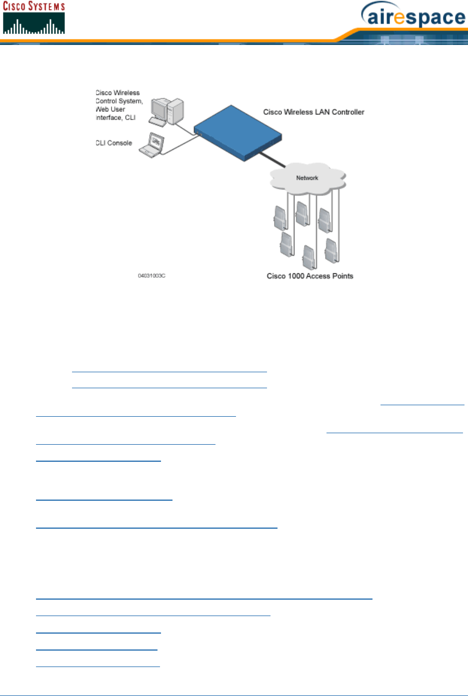
The following figure shows the Cisco SWAN components, which can be simultaneously deployed across
multiple floors and buildings.
Note: This document refers to Cisco Wireless LAN Controllers throughout. Refer to
the Cisco 2000 Series Wireless LAN Controllers and Cisco Wireless LAN Controllers
sections for more information.
3/11/05 About the Cisco Structured Wireless-Aware Network
OL-7426-02
Figure - Cisco SWAN Components
The Product Guide uses unique software to provide WLAN access for wireless clients and to simulta-
neously provide an active wireless access control system that protects your wired and wireless
infrastructure from negligent and malicious wireless attacks. The Cisco SWAN uses the following
components:
•Cisco Wireless LAN Controllers:
-Cisco 2000 Series Wireless LAN Controllers
-Cisco 4100 Series Wireless LAN Controllers
•Cisco 1000 Series IEEE 802.11a/b/g lightweight access points, described in Cisco 1000 Series
IEEE 802.11a/b/g Lightweight Access Points.
•Cisco 1030 remote edge lightweight access points, described in Cisco 1030 IEEE 802.11a/b/g
Remote Edge Lightweight Access Points.
•Operating System Software Software which provides all the Data and intrusion detection
features and functions while operating the Cisco Wireless LAN Controllers and Cisco 1000 Series
lightweight access points.
•Cisco Wireless Control System, or which manages the Cisco SWAN, and which provides location
to the nearest Cisco 1000 Series lightweight access point.
•Cisco Wireless Control System with Location Services, which manages the Cisco SWAN, and
which provides location to within ten meters.
The Cisco SWAN provides wireless access services to data clients and provides intrusion protection. As
such, it supports the full suite of Cisco Structured Wireless-Aware Network features and functions.
Refer to the following for more information:
•Single-Cisco Wireless LAN Controller Wireless LAN Controller Deployments
•Multiple-Cisco Wireless LAN Controller Deployments
•Operating System Software
•Operating System Security
•Cisco SWAN Wired Security

3/11/05 Single-Cisco Wireless LAN Controller Wireless LAN Controller Deployments
OL-7426-02
•Layer 2 and Layer 3 LWAPP Operation
•Radio Resource Management (RRM)
-Master Cisco Wireless LAN Controller
-Primary, Secondary, and Tertiary Cisco Wireless LAN Controllers
-Client Roaming
-External DHCP Servers
-Controller Mobility Group
-Cisco SWAN Wired Connections
-Cisco SWAN WLANs
-Transferring Files
-Power Over Ethernet
•Cisco Wireless LAN Controllers
•Cisco 1000 Series IEEE 802.11a/b/g Lightweight Access Points
•Rogue Access Points
•Cisco Wireless Control System
-Cisco WCS User Interface
-Cisco Wireless LAN Controller Autodiscovery
•Web User Interface
•Command Line Interface
Single-Cisco Wireless LAN Controller DeploymentsSingle-Cisco Wireless LAN Controller Wireless LAN Controller Deployments
As described in About the Cisco Structured Wireless-Aware Network, a standalone Cisco Wireless LAN
Controller can support Cisco 1000 Series lightweight access points across multiple floors and buildings
simultaneously, and supports the following features:
•Autodetecting and autoconfiguring Cisco 1000 Series lightweight access points as they are
added to the network, as described in Radio Resource Management (RRM).
•Full control of Cisco 1000 Series IEEE 802.11a/b/g Lightweight Access Points.
•Real-time control of system-wide WLAN Web, 802.1X, and IPSec security policies.
•Full control of up to 16 Cisco 1000 Series lightweight access point WLAN (SSID) policies, as
described in the Cisco 4100 Series Wireless LAN Controller Quick Start Guide.
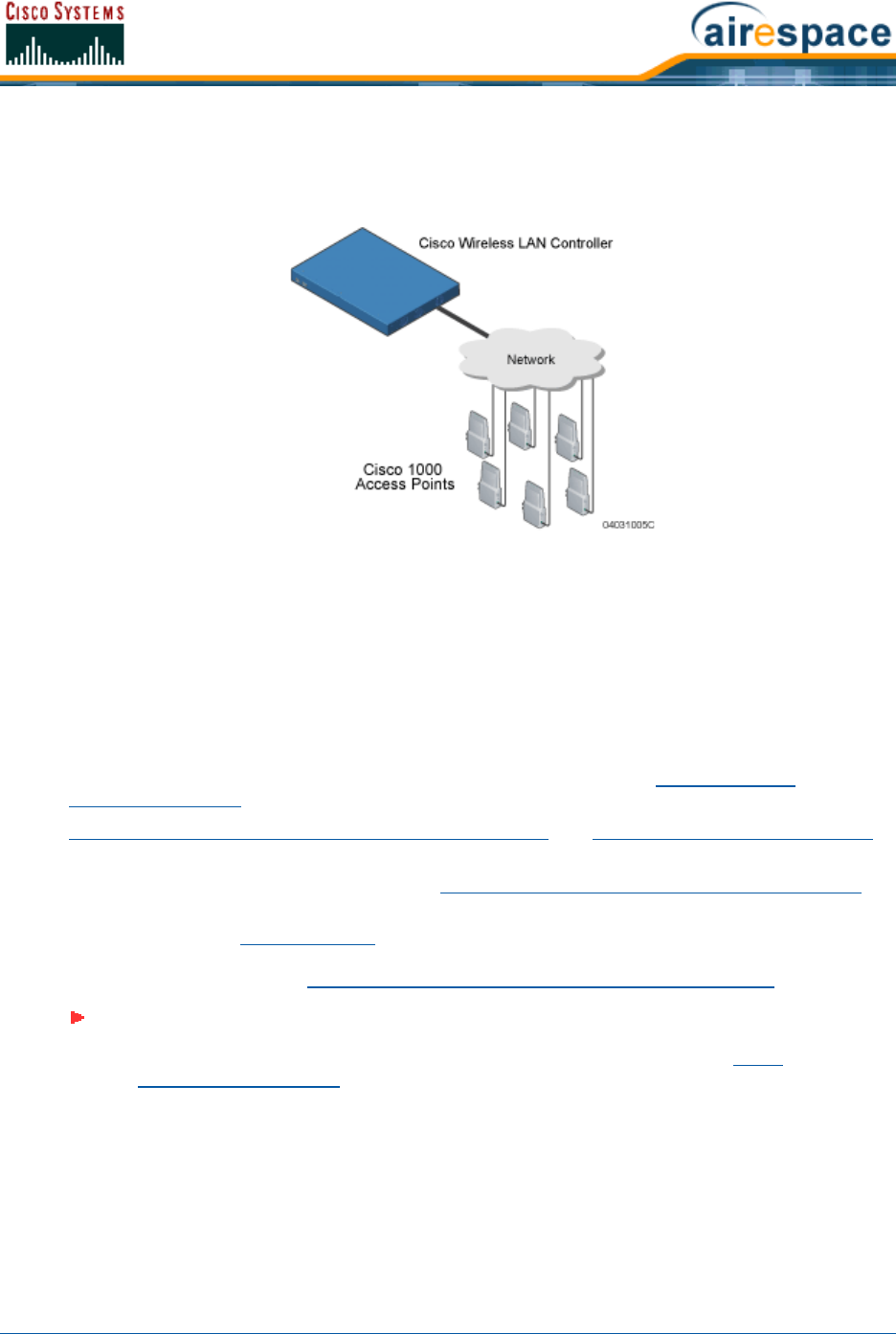
The following figures show a typical single Cisco Wireless LAN Controller deployed in Appliance Mode.
•Cisco 1000 Series lightweight access points connect to Cisco Wireless LAN Controllers through
the network. The network equipment may or may not provide Power Over Ethernet to the
access points.
Note that the Cisco 4100 Series Wireless LAN Controller uses two redundant GigE connections
to bypass single network failures. At any given time one of the Cisco 4100 Series Wireless LAN
Note: Cisco Wireless LAN Controllers can connect through the Management Interface
to multiple subnets in the Network. This can be helpful, for instance, when Network
operators want to confine multiple VLANs to separate subnets using Oper-
ator-Defined Interfaces.
3/11/05 Multiple-Cisco Wireless LAN Controller Deployments
OL-7426-02
Controller GigE connections is active and the other is passive. Upon a network failure, the
active connection becomes passive, and the passive connection becomes active.
Figure - Typical Cisco Wireless LAN Controller Deployment
Multiple-Cisco Wireless LAN Controller DeploymentsMultiple-Cisco Wireless LAN Controller Deployments
Each Cisco Wireless LAN Controller can support Cisco 1000 Series lightweight access points across
multiple floors and buildings simultaneously. Similarly, each Cisco Wireless LAN Controller can support
Cisco 1000 Series lightweight access points across multiple floors and buildings simultaneously.
However, full functionality of the Cisco SWAN is realized when it includes multiple Cisco Wireless LAN
Controllers. That is, a multiple-Cisco Wireless LAN Controller system has the following additional
features over a single-Cisco Wireless LAN Controller deployment:
•Autodetecting and autoconfiguring Cisco Wireless LAN Controller RF parameters as the Cisco
Wireless LAN Controllers are added to the network, as described in Radio Resource
Management (RRM).
•Same-Cisco Wireless LAN Controller (Layer 2) Roaming and Inter-Subnet (Layer 3) Roaming.
•Automatic Cisco 1000 Series lightweight access point failover to any redundant Cisco Wireless
LAN Controller with unused ports (refer to Cisco Wireless LAN Controller Failover Protection).
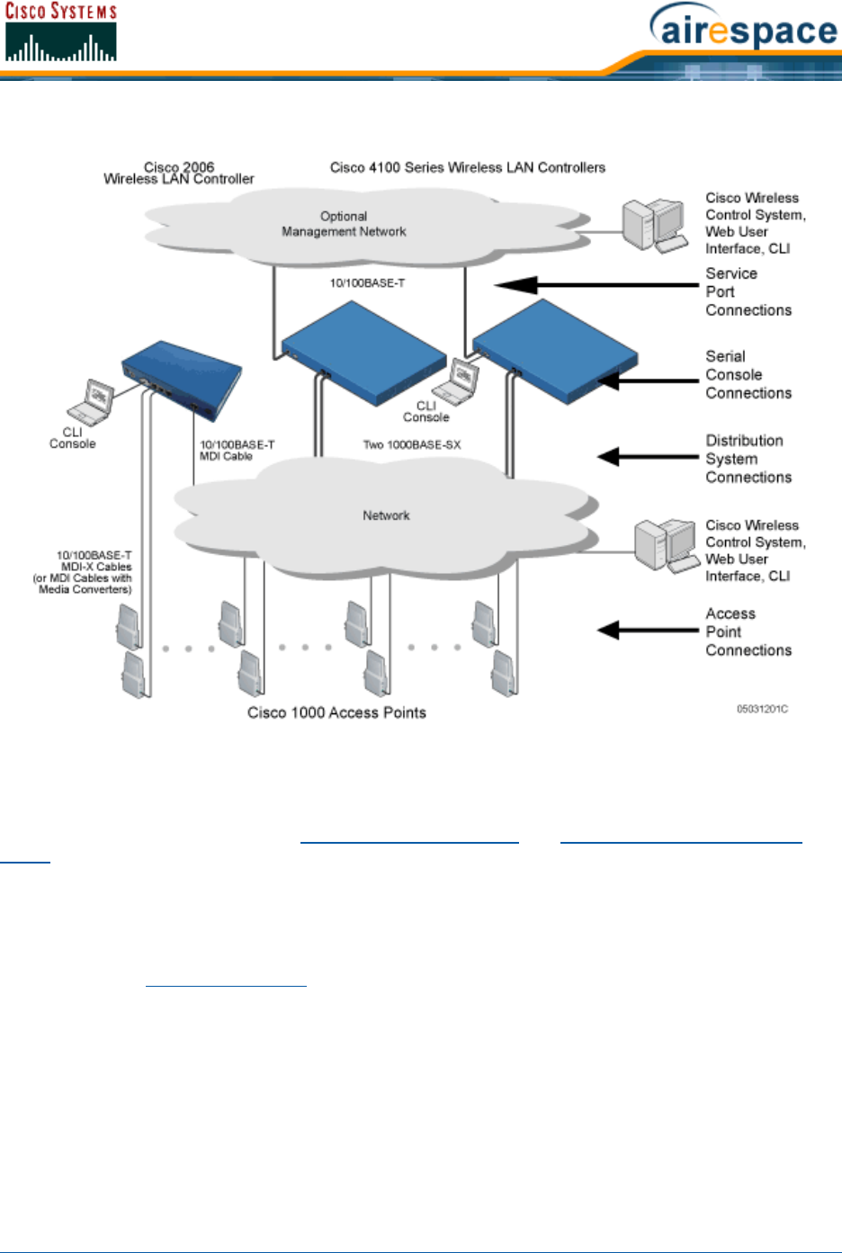
The following figure shows a typical multiple-Cisco Wireless LAN Controller deployment, with the Cisco
Wireless LAN Controllers in Appliance Mode. The figure also shows an optional dedicated Service
Network, and the three physical connection types between the network and the Cisco Wireless LAN
Controllers, as further described in Network Connection to Cisco Wireless LAN Controllers.
Note: Cisco Wireless LAN Controllers can connect through the Management Interface
to multiple subnets in the Network. This can be helpful, for instance, when Network
operators want to confine multiple VLANs to separate subnets using Oper-
ator-Defined Interfaces.
3/11/05 Operating System Software
OL-7426-02
Figure - Typical Multiple-Cisco Wireless LAN Controller Deployment
About the Operating System SoftwareOperating System Software
The Operating System Software controls Cisco Wireless LAN Controllers and Cisco 1000 Series light-
weight access points. It includes full Operating System Security and Radio Resource Management
(RRM) functions.
About Operating System SecurityOperating System Security
Operating System Security bundles Layer 1, Layer 2 and Layer 3 security components into a simple,
system-wide policy manager that creates independent security policies for each of up to 16 Cisco SWAN
WLANs. (Refer to Cisco SWAN WLANs.)
One of the barriers that made enterprises avoid deploying 802.11 networks was the inherent weakness
of 802.11 Static WEP (Wired Equivalent Privacy) encryption. Because WEP is so insecure, enterprises
have been looking for more secure solutions for business-critical traffic.
The 802.11 Static WEP weakness problem can be overcome using robust industry-standard security
solutions, such as:
•802.1X dynamic keys with EAP (extensible authentication protocol).
•WPA (Wi-Fi protected access) dynamic keys. The Cisco SWAN WPA implementation includes:
-TKIP + Michael (temporal key integrity protocol + message integrity code checksum)
dynamic keys, or

3/11/05 Cisco SWAN Wired Security
OL-7426-02
-WEP (Wired Equivalent Privacy) keys, with or without Pre-Shared key Passphrase.
•RSN with or without Pre-Shared key.
•Cranite FIPS140-2 compliant passthrough.
•Fortress FIPS140-2 compliant passthrough.
•Optional MAC Filtering.
The WEP problem can be further solved using industry-standard Layer 3 security solutions, such as:
•Terminated and passthrough VPNs (virtual private networks), and
•Terminated and passthrough L2TP (Layer Two Tunneling Protocol), which uses the IPSec (IP
Security) protocol.
•Terminated and pass-through IPSec (IP security) protocols. The terminated Cisco SWAN IPSec
implementation includes:
-IKE (internet key exchange),
-DH (Diffie-Hellman) groups, and
-Three optional levels of encryption: DES (ANSI X.3.92 data encryption standard), 3DES
(ANSI X9.52-1998 data encryption standard), or AES/CBC (advanced encryption
standard/cipher block chaining).
The Cisco SWAN IPSec implementation also includes industry-standard authentication using:
-MD5 (message digest algorithm), or
-SHA-1 (secure hash algorithm-1).
•The Cisco SWAN supports local and RADIUS MAC Address (media access control) filtering.
•The Cisco SWAN supports local and RADIUS user/password authentication.
•The Cisco SWAN also uses manual and automated Disabling to block access to network
services. In manual Disabling, the operator blocks access using client MAC addresses. In
automated Disabling, which is always active, the Operating System software automatically
blocks access to network services for an operator-defined period of time when a client fails to
authenticate for a fixed number of consecutive attempts. This can be used to deter brute-force
login attacks.
These and other Operating System Security features use industry-standard authorization and authenti-
cation methods to ensure the highest possible security for your business-critical wireless LAN traffic.
For information about Cisco SWAN wired security, refer to Cisco SWAN Wired Security.
About Cisco SWAN Wired SecurityCisco SWAN Wired Security
Many traditional Access Point vendors concentrate on security for the Wireless interface similar to that
described in the Operating System Security section. However, for secure Cisco Wireless LAN Controller
Service Interfaces (Cisco Wireless Control System, Web User Interface, and Command Line Interface),
Cisco Wireless LAN Controller-to-Cisco 1000 Series lightweight access point, and inter-Cisco Wireless
LAN Controller communications during device servicing and Client Roaming, the Operating System
includes built-in security.
Each Cisco Wireless LAN Controller and Cisco 1000 Series lightweight access point is manufactured with
a unique, signed X.509 certificate. This certificate is used to authenticate IPSec tunnels between
devices. These IPSec tunnels ensure secure communications for mobility and device servicing.
Cisco Wireless LAN Controllers and Cisco 1000 Series lightweight access points also use the signed
certificates to verify downloaded code before it is loaded, ensuring that hackers do not download
malicious code into any Cisco Wireless LAN Controller or Cisco 1000 Series lightweight access point.

3/11/05 Layer 2 and Layer 3 LWAPP Operation
OL-7426-02
For information about Cisco SWAN wireless security, refer to Operating System Security.
Layer 2 and Layer 3 LWAPP OperationLayer 2 and Layer 3 LWAPP Operation
The LWAPP communications between Cisco Wireless LAN Controllers and Cisco 1000 Series lightweight
access points can be conducted at ISO Data Link Layer 2 or Network Layer 3, when the connections are
made in Appliance Mode.
Operational RequirementsOperational Requirements
The requirement for Layer 2 LWAPP communications is that the Cisco Wireless LAN Controllers and
Cisco 1000 Series lightweight access points must be connected through Layer 2 devices on the same
subnet. This is the default operational mode for the Cisco SWAN. Note that when the Cisco Wireless
LAN Controller and Cisco 1000 Series lightweight access points are on different subnets, these devices
must be operated in Layer 3 mode.
The requirement for Layer 3 LWAPP communications is that the Cisco Wireless LAN Controllers and
Cisco 1000 Series lightweight access points can be connected directly to each other, connected through
Layer 2 devices on the same subnet, or connected through Layer 3 devices across subnets.
Note that all Cisco Wireless LAN Controllers in an Controller Mobility Group must use the same LWAPP
Layer 2 or Layer 3 mode, or you will defeat the Mobility software algorithm.
Configuration RequirementsConfiguration Requirements
When you are operating the Cisco SWAN in Layer 2 mode, you must configure a Management Interface
to control your Layer 2 communications.
When you are operating the Cisco SWAN in Layer 3 mode, you must configure a Management Interface
to control your Layer 2 communications, and an AP-Manager Interface to control Cisco 1000 Series
lightweight access point-to-Cisco Wireless LAN Controller Layer 3 communications.
About Radio Resource Management (RRM)Radio Resource Management (RRM)
Cisco is the only company to offer the powerful, comprehensive, and dynamic Radio Resource Manage-
ment (RRM) solution to the 802.11 market. The Radio Resource Management (RRM) (also known as
Radio Resource Management, or RRM) allows Cisco Wireless LAN Controllers to continually monitor
their associated Cisco 1000 Series lightweight access points for the following information:
•Traffic Load -- How much total bandwidth is used for transmitting and receiving traffic. This
allows WLAN managers to track and plan network growth ahead of client demand.
•Interference -- How much traffic is coming from other 802.11 sources.
•Noise -- How much non-802.11 noise is interfering with the currently assigned channel.
•Coverage -- Received Signal Strength (RSSI) and Signal to Noise Ratio (SNR) for all clients.
•Nearby APs.
Using the collected information, the Radio Resource Management (RRM) can periodically reconfigure
the 802.11 RF network within operator-defined limits for best efficiency. To do this, Radio Resource
Management (RRM):
•Dynamically reassigns channels to increase capacity and performance, both within the same
Cisco Wireless LAN Controller and across multiple Cisco Wireless LAN Controllers.
•Adjusts the transmit power to balance coverage and capacity, both within the same Cisco
Wireless LAN Controller and across multiple Cisco Wireless LAN Controllers.
•Allows the operator to assign nearby Cisco 1000 Series lightweight access points into groups to
streamline Radio Resource Management (RRM) algorithm processing.

3/11/05 Master Cisco Wireless LAN Controller
OL-7426-02
•As new clients associate, they are load balanced across grouped Cisco 1000 Series lightweight
access points reporting to each Cisco Wireless LAN Controller. This is particularly important
when many clients converge in one spot (such as a conference room or auditorium), because
Radio Resource Management (RRM) can automatically force some subscribers to associate with
nearby APs, allowing higher throughput for all clients.
•Automatically detects and configures new Cisco 1000 Series lightweight access points as they
are added to the network. The Radio Resource Management (RRM) automatically adjusts
nearby Cisco 1000 Series lightweight access points to accommodate the increased coverage
and capacity.
•Automatically detects and configures new Cisco Wireless LAN Controllers as they are added to
the network. The Radio Resource Management (RRM) automatically distributes associated Cisco
1000 Series lightweight access points to maximize coverage and capacity.
•Detects and reports coverage holes, where clients consistently connect to a Cisco 1000 Series
lightweight access point at a very low signal strength.
•Automatically defines Cisco Wireless LAN Controller Groups within operator-defined Controller
Mobility Groups.
The Radio Resource Management (RRM) solution thus allows the operator to avoid the costs of
laborious historical data interpretation and individual Cisco 1000 Series lightweight access point
reconfiguration. The power control features of Radio Resource Management (RRM) ensure client satis-
faction, and the coverage hole detection feature can alert the operator to the need for an additional (or
relocated) Cisco 1000 Series lightweight access point.
Note that the Radio Resource Management (RRM) uses separate monitoring and control for each of the
deployed networks: 802.11a and 802.11b/802.11g. Also note that the Radio Resource Management
(RRM) is automatically enabled, but can be customized or disabled for individual Cisco 1000 Series
lightweight access points.
Finally, for operators requiring easy manual configuration, the Radio Resource Management (RRM) can
recommend the best Cisco Radio settings, and then assign them on operator command.
The Radio Resource Management (RRM) controls produce a network that has optimal capacity, perfor-
mance, and reliability. The Radio Resource Management (RRM) functions also free the operator from
having to continually monitor the network for noise and interference problems, which can be transient
and difficult to troubleshoot. Finally, the Radio Resource Management (RRM) controls ensure that
clients enjoy a seamless, trouble-free connection through the Cisco SWAN 802.11 network.
About the Master Cisco Wireless LAN ControllerMaster Cisco Wireless LAN Controller
When you are adding Cisco 1000 Series lightweight access points to a Multiple-Cisco Wireless LAN
Controller Deployments network configured in Appliance Mode, it is convenient to have all Cisco 1000
Series lightweight access points associate with one Master Cisco Wireless LAN Controller on the same
subnet. That way, the operator does not have to log into multiple Cisco Wireless LAN Controllers to find
out which Cisco Wireless LAN Controller newly added Cisco 1000 Series lightweight access points asso-
ciated with.
One Cisco Wireless LAN Controller in each subnet can be assigned as the Master while adding Cisco
1000 Series lightweight access points. As long as a Master Cisco Wireless LAN Controller is active on
the same subnet, all new Cisco 1000 Series lightweight access points without a Primary, Secondary,
and Tertiary Cisco Wireless LAN Controllers assigned automatically attempt to associate with the Master
Cisco Wireless LAN Controller. This process is described in Cisco Wireless LAN Controller Failover
Protection.
The operator can monitor the Master Cisco Wireless LAN Controller using the Web User Interface or the
Cisco Wireless Control System GUI, and watch as Cisco 1000 Series lightweight access points associate
with the Master Cisco Wireless LAN Controllers configuration and assign a Primary, Secondary, and

3/11/05 Primary, Secondary, and Tertiary Cisco Wireless LAN Controllers
OL-7426-02
Tertiary Cisco Wireless LAN Controllers to the Cisco 1000 Series lightweight access point, and reboot
the Cisco 1000 Series lightweight access point so it reassociates with its Primary, Secondary, or
Tertiary Cisco Wireless LAN Controller.
About the Primary, Secondary, and Tertiary Cisco Wireless LAN ControllersPrimary, Secondary, and Tertiary Cisco
Wireless LAN Controllers
In Multiple-Cisco Wireless LAN Controller Deployments networks, Cisco 1000 Series lightweight access
points can associate with any Cisco Wireless LAN Controller on the same subnet. To ensure that each
Cisco 1000 Series lightweight access point associates with a particular Cisco Wireless LAN Controller,
the operator can assign Primary, Secondary, and Tertiary Cisco Wireless LAN Controllers to the Cisco
1000 Series lightweight access point.
When a Cisco 1000 Series lightweight access point is added to a network, it looks for its Primary,
Secondary, and Tertiary Cisco Wireless LAN Controllers first, then a Master Cisco Wireless LAN
Controller, then the least-loaded Cisco Wireless LAN Controller with available Cisco 1000 Series light-
weight access point ports. Refer to Cisco Wireless LAN Controller Failover Protection for more
information.
About Client RoamingClient Roaming
The Cisco SWAN supports seamless client roaming across Cisco 1000 Series lightweight access points
managed by the same Cisco Wireless LAN Controller, between Cisco Wireless LAN Controllers in the
same Controller Mobility Group on the same subnet, and across Cisco Wireless LAN Controllers in the
same Controller Mobility Group on different subnets. The following chapters describe the three modes
of roaming supported by the Cisco SWAN.
Same-Cisco Wireless LAN Controller (Layer 2) RoamingSame-Cisco Wireless LAN Controller (Layer 2) Roaming
Each Cisco Wireless LAN Controller supports same-Cisco Wireless LAN Controller client roaming across
Cisco 1000 Series lightweight access points managed by the same Cisco Wireless LAN Controller. This
roaming is transparent to the client, as the session is sustained and the client continues using the same
DHCP-assigned or client-assigned IP Address. The Cisco Wireless LAN Controller provides DHCP func-
tionality be providing a relay function. Same-Cisco Wireless LAN Controller roaming is supported in
Single-Cisco Wireless LAN Controller Wireless LAN Controller Deployments and Multiple-Cisco Wireless
LAN Controller Deployments.
Inter-Cisco Wireless LAN Controller (Layer 2) RoamingInter-Cisco Wireless LAN Controller (Layer 2) Roaming
Similarly, in Multiple-Cisco Wireless LAN Controller Deployments, the Cisco SWAN supports client
roaming across Cisco 1000 Series lightweight access points managed by Cisco Wireless LAN Controllers
in the same Controller Mobility Group and on the same subnet. This roaming is also transparent to the
client, as the session is sustained and a tunnel between Cisco Wireless LAN Controllers allows the client
to continue using the same DHCP- or client-assigned IP Address as long as the session remains active.
Note that the tunnel is torn down and the client must reauthenticate when the client sends a DHCP
Note: Cisco 1000 Series lightweight access points without a Primary, Secondary, and
Tertiary Cisco Wireless LAN Controllers assigned always search for a Master Cisco
Wireless LAN Controller first upon reboot. After adding Cisco 1000 Series lightweight
access points through the Master, assign Primary, Secondary, and Tertiary Cisco
Wireless LAN Controllers to each Cisco 1000 Series lightweight access point.
Cisco recommends that you disable the Master setting on all Cisco Wireless LAN
Controllers after initial configuration.
Because the Master Cisco Wireless LAN Controller is normally not used in a deployed
network, the Master setting is automatically disabled upon reboot or OS code
upgrade.

3/11/05 Client Location
OL-7426-02
Discover with a 0.0.0.0 client IP Address or a 169.254.*.* client auto-IP Address, or when the oper-
ator-set session timeout is exceeded.
Note that the Cisco 1030 remote edge lightweight access points at a remote location must be on the
same subnet to support roaming.
Inter-Subnet (Layer 3) RoamingInter-Subnet (Layer 3) Roaming
Similarly, in Multiple-Cisco Wireless LAN Controller Deployments, the Cisco SWAN supports client
roaming across Cisco 1000 Series lightweight access points managed by Cisco Wireless LAN Controllers
in the same Controller Mobility Group on different subnets. This roaming is transparent to the client,
because the session is sustained and a tunnel between the Cisco Wireless LAN Controllers allows the
client to continue using the same DHCP-assigned or client-assigned IP Address as long as the session
remains active. Note that the tunnel is torn down and the client must reauthenticate when the client
sends a DHCP Discover with a 0.0.0.0 client IP Address or a 169.254.*.* client auto-IP Address, or
when the operator-set session timeout is exceeded.
Note that the Cisco 1030 remote edge lightweight access points at a remote location must be on the
same subnet to support roaming.
Special Case: Voice Over IP Telephone RoamingSpecial Case: Voice Over IP Telephone Roaming
802.11 VoIP telephones actively seek out associations with the strongest RF signal to ensure best
Quality of Service (QoS) and maximum throughput. The minimum VoIP telephone requirement of
20 millisecond or shorter latency time for the roaming handover is easily met by the Cisco SWAN, which
has an average handover latency of nine or fewer milliseconds.
This short latency period is controlled by Cisco Wireless LAN Controllers, rather than allowing indepen-
dent APs to negotiate roaming handovers.
The Cisco SWAN supports 802.11 VoIP telephone roaming across Cisco 1000 Series lightweight access
points managed by Cisco Wireless LAN Controllers on different subnets, as long as the Cisco Wireless
LAN Controllers are in the same Controller Mobility Group. This roaming is transparent to the VoIP tele-
phone, because the session is sustained and a tunnel between Cisco Wireless LAN Controllers allows the
VoIP telephone to continue using the same DHCP-assigned IP Address as long as the session remains
active. Note that the tunnel is torn down and the VoIP client must reauthenticate when the VoIP
telephone sends a DHCP Discover with a 0.0.0.0 VoIP telephone IP Address or a 169.254.*.* VoIP
telephone auto-IP Address, or when the operator-set session timeout is exceeded.
About Client LocationClient Location
The Cisco SWAN periodically determines client location and stores the locations in the Cisco WCS
database. To view the client location history, display the Cisco WCS Monitor Client <client> -
<vendor:MACaddr> page and select Recent Map (High Resolution) or Present Map (High Resolution).
About External DHCP ServersExternal DHCP Servers
The Operating System is designed to appear as a DHCP Relay to the network and as a DHCP Server to
clients with industry-standard external DHCP Servers that support DHCP Relay. This means that each
Cisco Wireless LAN Controller appears as a DHCP Relay agent to the DHCP Server. This also means that
the Cisco Wireless LAN Controller appears as a DHCP Server at the virtual IP Address to wireless clients.
Because the Cisco Wireless LAN Controller captures the client IP Address obtained from a DHCP Server,
it maintains the same IP Address for that client during same-Cisco Wireless LAN Controller, inter-Cisco
Wireless LAN Controller, and inter-subnet Client Roaming.

3/11/05 Controller Mobility Group
OL-7426-02
Per-WLAN AssignmentPer-WLAN Assignment
All Cisco SWAN WLANs can be configured to use the same or different DHCP Servers, or no DHCP
Server. This allows operators considerable flexibility in configuring their Wireless LANs, as further
described in the Cisco SWAN WLANs section.
Note that Cisco SWAN WLANs that support Management over Wireless must allow the management
(device servicing) clients to obtain an IP Address from a DHCP Server.
Per-Interface AssignmentPer-Interface Assignment
•The Layer 2 Management Interface can be configured for a primary and secondary DHCP
server.
•The Layer 3 AP-Manager Interface can be configured for a primary and secondary DHCP server.
•Each of the Operator-Defined Interfaces can be configured for a primary and secondary DHCP
server.
•The Virtual Interface does not use DHCP servers.
•The Service-Port Interface can be configured to enable or disable DHCP servers.
Security ConsiderationsSecurity Considerations
For enhanced security, it is recommended that operators require all clients to obtain their IP Addresses
from a DHCP server. To enforce this requirement, all Cisco SWAN WLANs can be configured with a
‘DHCP Required’ setting and a valid DHCP Server IP Address, which disallows client static IP Addresses.
If a client associating with a WLAN with ‘DHCP Required’ set does not obtain its IP Address from the
designated DHCP Server, it is not allowed access to any network services.
Note that if ‘DHCP Required’ is selected, clients must obtain an IP address via DHCP. Any client with a
static IP address will not be allowed on the network. The Cisco Wireless LAN Controller monitors DHCP
traffic since it acts as a DHCP proxy for the clients.
If slightly less security is tolerable, operators can create Cisco SWAN WLANs with ‘DHCP Required’
disabled and a valid DHCP Server IP Address. Clients then have the option of using a static IP Address
or obtaining an IP Address from the designated DHCP Server.
Operators are also allowed to create separate Cisco SWAN WLANs with ‘DHCP Required’ disabled and a
DHCP Server IP Address of 0.0.0.0. These WLANs drop all DHCP requests and force clients to use a
static IP Address. Note that these WLANs do not support Management over Wireless.
About Controller Mobility GroupsController Mobility Group
Network operators can define Controller Mobility Groups to allow client roaming across groups of Cisco
Wireless LAN Controllers. Because the Cisco Wireless LAN Controllers in Multiple-Cisco Wireless LAN
Controller Deployments can detect each other across the network and over the air, it is important that
each enterprise, institution, and wireless internet service provider isolate their Cisco Wireless LAN
Controllers. The Operating System makes it easy for operators to create this isolation by allowing them
to assign a Controller Mobility Group Name to their Cisco Wireless LAN Controllers. This assignment can
be made using the Web User Interface, the Cisco Wireless Control System, or the Command Line
Interface.
Note that all the Cisco Wireless LAN Controllers in a Controller Mobility Group must use the same
LWAPP Layer 2 and Layer 3 LWAPP Operation, or you will defeat the Mobility software algorithm.
The following figure shows the results of creating Controller Mobility Group Names for two groups of
Cisco Wireless LAN Controllers. The Cisco Wireless LAN Controllers in the ABC Controller Mobility Group
recognize and communicate with each other through their Cisco 1000 Series IEEE 802.11a/b/g Light-
weight Access Points and Cisco 1030 IEEE 802.11a/b/g Remote Edge Lightweight Access Points and
through their shared subnets, but the ABC Controller Mobility Group tags the XYZ Cisco 1000 Series
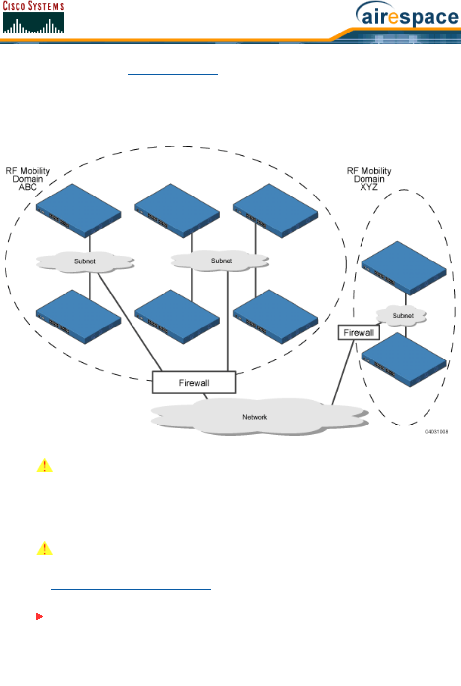
3/11/05 Controller Mobility Group
OL-7426-02
lightweight access points as Rogue Access Points. Likewise, the Cisco Wireless LAN Controllers in the
XYZ Controller Mobility Group do not recognize or communicate with the Cisco Wireless LAN Controllers
in the ABC Controller Mobility Group. This feature ensures Controller Mobility Group isolation across the
network.
Figure - Typical Controller Mobility Group Name Application
The Controller Mobility Group feature can also be used to limit roaming between different floors, build-
ings, or campuses in the same enterprise by assigning different Controller Mobility Group names to
different Cisco Wireless LAN Controllers within the same wireless network.
If enabled, Radio Resource Management (RRM) operation is constrained within each Controller Mobility
Group.
CAUTION: Cisco recommends that you assign one set of VLANs for WLANs and a
different set of VLANs for Management Interfaces to ensure that Cisco Wireless LAN
Controllers properly route VLAN traffic.
CAUTION: The Cisco SWAN does not support simultaneous inter-switch and
inter-subnet roaming. Either install all the Controller Mobility Group members in the
same subnet or install all the Controller Mobility Group members in different subnets.
Note: Because the Cisco Wireless LAN Controllers talk to each other when they are in
the same Controller Mobility Group, Cisco recommends that operators do not add
physically separated Cisco Wireless LAN Controllers to the same static Controller
Mobility Group to avoid unnecessary traffic on the network.
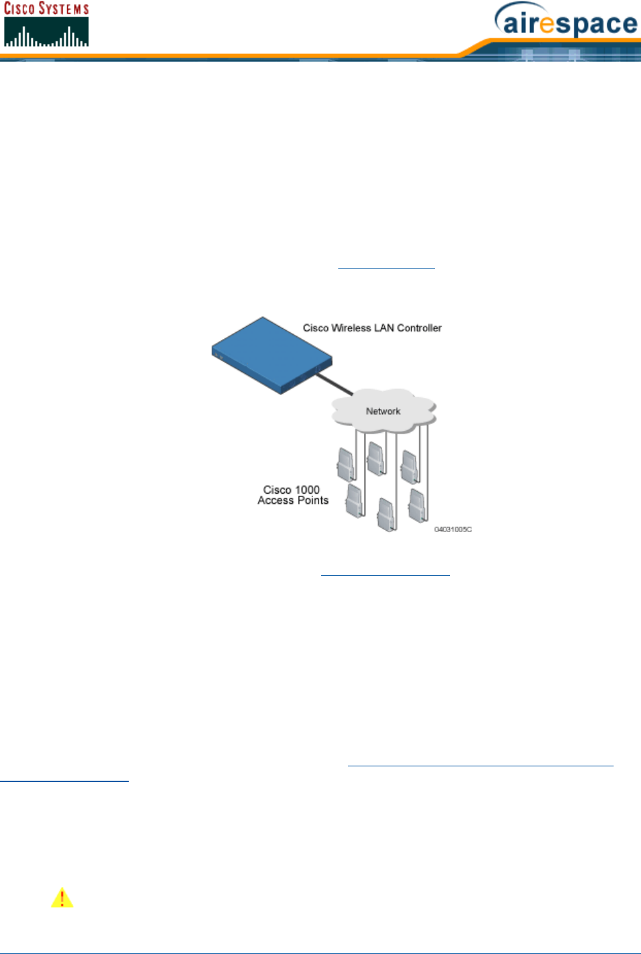
3/11/05 Cisco SWAN Wired Connections
OL-7426-02
About Cisco SWAN Wired ConnectionsCisco SWAN Wired Connections
The Cisco SWAN components communicate with each other using industry-standard Ethernet cables
and connectors. The following sections contain details of the Cisco SWAN wired connections.
Between Cisco Wireless LAN Controllers and Cisco 1000 Series Lightweight Access PointsBetween Cisco Wireless LAN
Controllers and Cisco 1000 Series Lightweight Access Points
The Cisco 4100 Series Wireless LAN Controller connects to the network using two fiber-optic GigE
cables: two redundant GigE connections to bypass single network failures. At any given time one of the
Cisco 4100 Series Wireless LAN Controller GigE connections is active and the other is passive. Upon a
network failure, the active connection becomes passive, and the passive connection becomes active.
Cisco 4100 Series Wireless LAN Controllers operate in Appliance Mode, and do not connect directly to
any access points. The Cisco 1000 Series lightweight access points communicate with the Cisco 4100
Series Wireless LAN Controller through the network.
The standard CAT-5 cable can also be used to conduct power for the Cisco 1000 Series lightweight
access points from a network device equipped with Power Over Ethernet (PoE) capability. This power
distribution plan can be used to reduce the cost of individual AP power supplies and related cabling.
Between Cisco 4100 Series Wireless LAN Controllers and Other Network DevicesBetween Cisco 4100 Series Wireless LAN Controllers and Other Network Devices
The Cisco 4100 Series Wireless LAN Controller connects to the network using two front-panel fiber-optic
GigE cables: two redundant GigE connections to bypass single network failures. At any given time one
of the Cisco 4100 Series Wireless LAN Controller GigE connections is active and the other is passive.
Upon a network failure, the active connection becomes passive, and the passive connection becomes
active.
About Cisco SWAN WLANsCisco SWAN WLANs
The Cisco SWAN can control up to 16 Wireless LANs for Cisco 1000 Series IEEE 802.11a/b/g Light-
weight Access Points. Each WLAN has a separate WLAN ID (1 through 16), a separate WLAN SSID
(WLAN Name), and can be assigned unique security policies.
The Cisco 1000 Series lightweight access points broadcast all active Cisco SWAN WLAN SSIDs and
enforce the policies defined for each WLAN.
Note that many enterprises use different WLANs to separate traffic for different sections or
departments.
CAUTION: Cisco recommends that you assign one set of VLANs for WLANs and a
different set of VLANs for Management Interfaces to ensure that Cisco Wireless LAN
Controllers properly route VLAN traffic.

3/11/05 Access Control Lists
OL-7426-02
If Management over Wireless is enabled across the Cisco SWAN, the Network operator can manage the
System across the enabled WLAN using CLI and Telnet (Command Line Interface), http/https (Web
User Interface), and SNMP (Cisco Wireless Control System).
To configure the Cisco SWAN WLANs, refer to Configuring WLANs.
About Access Control ListsAccess Control Lists
The Operating System allows you to define up to 64 Access Control Lists (ACLs), similar to standard
firewall Access Control Lists. Each ACL can have up to 64 Rules (filters).
Operators can use ACLs to control client access to multiple VPN servers within a given WLAN. If all the
clients on a WLAN must access a single VPN server, use the IPSec/VPN Gateway Passthrough setting in
IPSec Passthrough, WLANs > Edit or Configure <IPaddr> > WLAN > Add From Template section.
After they are defined, the ACLs can be applied to the Management Interface, the AP-Manager Inter-
face, or any of the Operator-Defined Interfaces.
Refer to Access Control Lists > New in the Web User Interface Online Help or Creating Access Control
Lists in the Configuring the Cisco Wireless LAN Controllers sections for instructions on how to configure
the Access Control Lists.
About Identity NetworkingIdentity Networking
Cisco Wireless LAN Controllers can have the following parameters applied to all clients associating with
a particular WLAN: QoS, global or Interface-specific DHCP server, Layer 2 and Layer 3 Security Policies,
and default Interface (which includes physical port, VLAN and ACL assignments).
However, the Cisco Wireless LAN Controller can also have individual clients (MAC addresses) override
the preset WLAN parameters by using MAC Filtering or by Allowing AAA Override parameters. This
configuration can be used, for example, to have all company clients log into the corporate WLAN, and
then have clients connect using different QoS, DHCP server, Layer 2 and Layer 3 Security Policies, and
Interface (which includes physical port, VLAN and ACL assignments) settings on a per-MAC Address
basis.
When Network operators configure MAC Filtering for a client, they can assign a different VLAN to the
MAC Address, which can be used to have OS automatically reroute the client to the Management
Interface or any of the Operator-Defined Interfaces, each of which have their own VLAN, ACL, DHCP
server, and physical port assignments. This MAC Filtering can be used as a coarse version of AAA
Override, and normally takes precedence over any AAA (RADIUS or other) Override.
However, when Allow AAA Override is enabled, the RADIUS (or other AAA) server can alternatively be
configured to return QoS and ACL on a per-MAC Address basis. Allow AAA Override gives the AAA
Override precedence over the MAC Filtering parameters set in the Cisco Wireless LAN Controller; if
there are no AAA Overrides available for a given MAC Address, the OS uses the MAC Filtering parame-
ters already in the Cisco Wireless LAN Controller. This AAA (RADIUS or other) Override can be used as
a finer version of AAA Override, but only takes precedence over MAC Filtering when Allow AAA Override
is enabled.
Note that in all cases, the Override parameters (Operator-Defined Interface and QoS, for example)
must already be defined in the Cisco Wireless LAN Controller configuration.
In all cases, the OS will use QoS and ACL provided by the AAA server or MAC Filtering regardless of the
Layer 2 and/or Layer 3 authentication used.
Also note that the OS will only move clients from the default Cisco SWAN WLAN VLAN to a different
VLAN when configured for MAC filtering, 802.1X, and/or WPA Layer 2 authentication.
To configure the Cisco SWAN WLANs, refer to Configuring WLANs.

3/11/05 Transferring Files
OL-7426-02
About File TransfersTransferring Files
The Network operator can upload and download Operating System code, configuration, and certificate
files to and from a Cisco 2000 Series Wireless LAN Controller and/or Cisco 4100 Series Wireless LAN
Controller using CLI, Web User Interface, or Cisco Wireless Control System (Cisco WCS) commands.
•To use CLI commands, refer to Transferring Files To and From a Cisco Wireless LAN Controller.
•To use the Web User Interface, go to Using the Web User Interface.
•To use Cisco WCS commands, continue with Using the Cisco Wireless Control System.
About Power Over EthernetPower Over Ethernet
Cisco 1000 Series lightweight access points support 802.3af-compatible Power over Ethernet (PoE),
which can reduce the cost of discrete power supplies, additional wiring, conduits, outlets, and installer
time. PoE also frees installers from having to mount Cisco 1000 Series IEEE 802.11a/b/g Lightweight
Access Points, Cisco 1030 IEEE 802.11a/b/g Remote Edge Lightweight Access Points or other powered
equipment near AC outlets, providing greater flexibility in positioning Cisco 1000 Series lightweight
access points for maximum coverage.
When you are using PoE, the installer runs a single CAT-5 cable from each Cisco 1000 Series light-
weight access point to a PoE power hub or to a Cisco Single-Line PoE Injector, described in Cisco 1000
Series Lightweight Access Point Models. When the PoE equipment determines that the Cisco 1000
Series lightweight access point is PoE-enabled, it sends 48 VDC over the unused pairs in the Ethernet
cable to power the access point.
The PoE cable length is limited by the 100BASE-T or 10BASE-T specification to 100 m or 200 m,
respectively.
Pico Cell FunctionalityPico Cell Functionality
Pico Cell functionality includes optimization of the OS to support this functionality as follows:
•The Cisco WCS Pico Cell Mode parameter reconfigures OS parameters, allowing OS to function
efficiently in pico cell deployments. Note that when the operator is deploying a pico cell network
the OS must also have more memory allocated (512 to 2048 MB) using the config database
size 2048 CLI command.
•Client mobility between multiple mobility domains when such exist.
•Addition of a WPA2 VFF extension to eliminate the need to re-key after every association. This
allows the re-use of existing PTK and GTK.
•With WPA2 PMK caching and VFF, the PMK cache is transferred as part of context transfer prior
to the authentication phase. This allows expedited handoffs to work for both intra- and
inter-Cisco Wireless LAN Controller roaming events.
•A beacon/probe response that allows a Cisco 1000 Series lightweight access point to indicate
which switch it is attached to so that reauthorization events will only occur when needed,
minimizing inter-switch handoffs and thus reducing CPU usage.
•Ability to change AP sensitivity for pico cells.
Note: Cisco 1000 Series lightweight access points can receive power from any other
network device conforming to the IEEE 802.3af standard.
Note: Each Cisco 1000 Series lightweight access point can alternatively receive
power from one Cisco 1000 Series Lightweight Access Point External Power Supply.

3/11/05 Intrusion Detection Service (IDS)
OL-7426-02
•Control of AP fall back behavior to optimize pico cell use.
•Heat map support for directional antennas.
•Specific control over blacklisting events
•Ability to configure and view basic LWAPP configuration elements using the AP’s CLI.
Intrusion Detection Service (IDS)Intrusion Detection Service (IDS)
Intrusion Detection Service includes the following:
•Sensing Clients probing for “ANY” SSID
•Sensing if AeS is being contained
•Notification of MiM Attacks, NetStumbler, Wellenreiter
•Management Frame Detection and RF Jamming Detection
•Airjack Detection (Spoofed Deauthorization detection)
•Broadcast Deauthorization Detection
•Null Probe Response Detection
•Fake AP Detection
•Detection of Weak WEP Encryption
•MAC Spoofing Detection
•AP Impersonation Detection
•Honeypot AP Detection
•Valid Station Protection
•Misconfigured AP Protection
•Rogue AP Detection
•AD-HOC Detection and Protection
•Wireless Bridge Detection
•Asleep Detection / Protection

3/11/05 Cisco Wireless LAN Controllers
OL-7426-02
About Cisco Wireless LAN ControllersCisco Wireless LAN Controllers
Cisco 4100 Series Wireless LAN Controllers are enterprise-class high-performance wireless switching
platforms that support 802.11a and 802.11b/802.11g protocols. They operate under control of the
Operating System, which includes the Radio Resource Management (RRM), resulting in Cisco 2000
Series Wireless LAN Controllers that can automatically adjust to real-time changes in the 802.11 RF
environment. The Cisco 4100 Series Wireless LAN Controllers are built around high-performance
network and security hardware, resulting in highly reliable 802.11 enterprise networks with unparal-
leled security. Also see:
•Cisco 2000 Series Wireless LAN Controllers
•Cisco 4100 Series Wireless LAN Controllers
•Cisco Wireless LAN Controller Features
•Cisco 2000 Series Wireless LAN Controller Model Numbers
•Appliance Mode
•Distribution System Ports
•Management Interface
•AP-Manager Interface
•Operator-Defined Interfaces
•Virtual Interface
•Service Port
•Service-Port Interface
•Startup Wizard
•Cisco Wireless LAN Controller Memory
•Cisco Wireless LAN Controller Failover Protection
•Cisco Wireless LAN Controller Automatic Time Setting
•Cisco Wireless LAN Controller Time Zones
•Network Connection to Cisco Wireless LAN Controllers
•VPN/Enhanced Security Module
•Cisco SWAN Wired Connections
•Cisco 1000 Series IEEE 802.11a/b/g Lightweight Access Points
•Cisco 1030 IEEE 802.11a/b/g Remote Edge Lightweight Access Points
•Cisco SWAN WLANs
•Identity Networking
•Configuring the Cisco Wireless LAN Controllers
•Transferring Files To and From a Cisco Wireless LAN Controller
•Updating the Operating System Software
•Clearing Configurations
•Resetting the Cisco Wireless LAN Controller
•Cisco 4100 Series Wireless LAN Controller Quick Start Guide
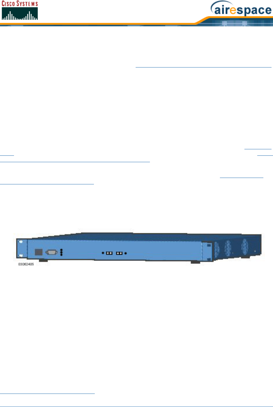
3/11/05 Cisco 2000 Series Wireless LAN Controllers
OL-7426-02
About Cisco 2000 Series Wireless LAN ControllersCisco 2000 Series Wireless LAN Controllers
The Cisco 2000 Series Wireless LAN Controller is part of the Cisco SWAN. The Cisco 2000 Series
Wireless LAN Controller controls up to six Cisco 1000 Series lightweight access points, making it ideal
for smaller enterprise and low-density applications. About the Cisco Structured Wireless-Aware Network
gives a comprehensive overview of the Cisco SWAN and the place of the Cisco 2000 Series Wireless
LAN Controller in that system.
The Cisco 2000 Series Wireless LAN Controller is a slim 9.5 x 6.0 x 1.6 in. (241 x 152 x 41 mm) chassis
that can be desktop or shelf mounted. The Cisco 2000 Series Wireless LAN Controller front panel has
one POWER LED and four sets of Ethernet LAN Port status LEDs, which indicate 10 MHz or 100 MHz
connections and transmit/receive Activity for the four corresponding back-panel Ethernet LAN connec-
tors. The Cisco 2000 Series Wireless LAN Controller is shipped with four rubber mounting feet.
Cisco 4100 Series Wireless LAN ControllersCisco 4100 Series Wireless LAN Controllers
The Cisco 4100 Series Wireless LAN Controller is part of the Cisco SWAN. The Cisco 4100 Series
Wireless LAN Controller is one unit high, and communicates indirectly through the network (Appliance
Mode) with up to 12 (Model 4112), up to 24 (Model 4124), or up to 36 (Model 4136), associated Cisco
1000 Series IEEE 802.11a/b/g Lightweight Access Points, making it ideal for larger enterprise and
high-density applications.
Cisco 4100 Series Wireless LAN Controller support the Cisco SWAN as described in About the Cisco
Structured Wireless-Aware Network, which gives a comprehensive overview of the Cisco SWAN and the
place of the Cisco 4100 Series Wireless LAN Controllers in that system.
The following figure shows the Cisco 4100 Series Wireless LAN Controller, which has two redundant
front-panel SX/LC jacks.
Figure - Cisco 4100 Series Wireless LAN Controller
Cisco 4100 Series Wireless LAN Controllers can be factory-ordered with a VPN/Enhanced Security
Module (Crypto Card) to support VPN, IPSec and other processor-intensive tasks, and contain two
1000BASE-SX network connectors that allow the Cisco 4100 Series Wireless LAN Controller to commu-
nicate with the network at GigE (Gigabit Ethernet) speeds. The 1000BASE-SX network connectors
provide 100/1000 Mbps wired connections to a network through 850nM (SX) fiber-optic links using LC
physical connectors.
The two redundant GigE connections on the Cisco 4100 Series Wireless LAN Controller allow the Cisco
4100 Series Wireless LAN Controller to bypass single network failures. At any given time one of the
Cisco 4100 Series Wireless LAN Controller GigE connections is active and the other is passive. Upon a
network failure, the active connection becomes passive, and the passive connection becomes active.
Cisco Wireless LAN Controller FeaturesCisco Wireless LAN Controller Features
Cisco 2000 Series Wireless LAN Controllers connect to the associated Cisco 1000 Series lightweight
access points through the network.
After each Cisco 2000 Series Wireless LAN Controller is installed and configured, the Operating System
Radio Resource Management (RRM) is activated, and the Operating System manages and controls

3/11/05 Cisco Wireless LAN Controller Features
OL-7426-02
associated Cisco 1000 Series lightweight access points with information about their relative positions,
IP Addresses, and MAC addresses. This information allows all Cisco Wireless LAN Controllers within
each Controller Mobility Group to constantly monitor and dynamically adjust the RF environment, maxi-
mizing performance, minimizing interference, and distributing the client load.
Cisco 2000 Series Wireless LAN Controllers communicate with Cisco 1000 Series lightweight access
points via 1000BASE-SX cables through the network. Note that the Cisco 2000 Series Wireless LAN
Controller uses two redundant GigE connections to bypass single network failures. At any given time
one of the Cisco 4100 Series Wireless LAN Controller GigE connections is active and the other is
passive. Upon a network failure, the active connection becomes passive, and the passive connection
becomes active.
The Cisco 2000 Series Wireless LAN Controller communicates with network via two 1000BASE-SX
Network Ports: the Cisco 2000 Series Wireless LAN Controller uses two redundant GigE connections to
bypass single network failures.
The network operator can control the Cisco Wireless LAN Controllers with the following Operating
System device interfaces:
•With optional Cisco Wireless Control System (Cisco WCS) inband or out-of-band via a
front-panel 10/100BASE-T Service port (Service Interface), or via the network (Management
Interface).
•With the built-in Command Line Interface via a serial RS232-C Console Port (direct connection),
or via the network (Telnet connection).
•With the built-in Web User Interface via a dedicated 10/100BASE-T Service port (recom-
mended), or via the network, using either http or https (http + SSL).
Refer to the following for more information about Cisco Wireless LAN Controllers:
•Cisco 2000 Series Wireless LAN Controllers
•Cisco 4100 Series Wireless LAN Controllers
•Cisco Wireless LAN Controller Features
•Cisco 2000 Series Wireless LAN Controller Model Numbers
•Cisco 4100 Series Wireless LAN Controller Model Numbers
•Appliance Mode
•Distribution System Ports
•Management Interface
•AP-Manager Interface
•Operator-Defined Interfaces
•Virtual Interface
•Service Port
•Service-Port Interface
•Startup Wizard
•Cisco Wireless LAN Controller Memory
•Cisco Wireless LAN Controller Failover Protection
•Cisco Wireless LAN Controller Automatic Time Setting
•Cisco Wireless LAN Controller Time Zones
•Network Connection to Cisco Wireless LAN Controllers

3/11/05 Cisco 2000 Series Wireless LAN Controller Model Numbers
OL-7426-02
•VPN/Enhanced Security Module
•Cisco SWAN Wired Connections
•Cisco 1000 Series IEEE 802.11a/b/g Lightweight Access Points
•Cisco 1030 IEEE 802.11a/b/g Remote Edge Lightweight Access Points
•Cisco SWAN Wired Connections
•Cisco SWAN WLANs
•Configuring the Cisco Wireless LAN Controllers
•Transferring Files To and From a Cisco Wireless LAN Controller
•Updating the Operating System Software
•Clearing Configurations
•Resetting the Cisco Wireless LAN Controller
•Cisco 4100 Series Wireless LAN Controller Quick Start Guide
Cisco 2000 Series Wireless LAN Controller Model NumbersCisco 2000 Series Wireless LAN Controller Model Numbers
Cisco 2000 Series Wireless LAN Controller model number is as follows:
•AIR-WLC2006-K9 - The Cisco 2000 Series Wireless LAN Controller communicates with up to six
Cisco 1000 Series lightweight access points.
Note that the Cisco 2000 Series Wireless LAN Controllers come from the factory with tabletop mounting
feet.
The following upgrade is also available:
•Cisco 2000 Series Wireless LAN Controller Rack Mount Kit - Designed to mount a Cisco 2000
Series Wireless LAN Controller and its external Power Supply Module in a 19-inch (48.26 cm)
EIA equipment rack
Cisco 4100 Series Wireless LAN Controller Model NumbersCisco 4100 Series Wireless LAN Controller Model Numbers
Cisco 4100 Series Wireless LAN Controller model numbers are as follows:
•AIR-WLC4112-K9 - The Cisco 4100 Series Wireless LAN Controller uses two redundant GigE
connections to bypass single network failures, and communicates with up to 12 Cisco 1000
Series lightweight access points. That is, at any given time one of the Cisco 4100 Series
Wireless LAN Controller GigE connections is active and the other is passive. Upon a network
failure, the active connection becomes passive, and the passive connection becomes active.
Note that the 1000BASE-SX Network Adapters provide 100/1000 Mbps wired connections to a
network through 850nM (SX) fiber-optic links using LC physical connectors.
•AIR-WLC4124-K9 - The Cisco 4100 Series Wireless LAN Controller uses two redundant GigE
connections to bypass single network failures, and communicates with up to 24 Cisco 1000
Series lightweight access points.
•AIR-WLC4136-K9 - The Cisco 4100 Series Wireless LAN Controller uses two redundant GigE
connections to bypass single network failures, and communicates with up to 36 Cisco 1000
Series lightweight access points.
Note that all Cisco 4100 Series Wireless LAN Controller models come from the factory with 19-inch EIA
equipment rack flush-mount ears and tabletop mounting feet.
The following upgrade module is also available:
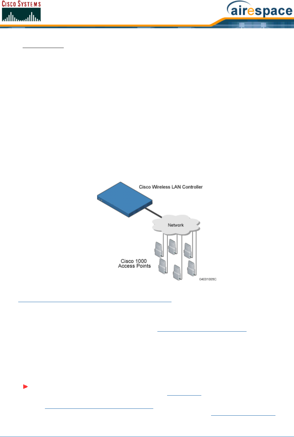
3/11/05 Appliance Mode
OL-7426-02
•AIR-VPN-4100 - VPN/Enhanced Security Module: Supports VPN, L2TP, IPSec and other
processor-intensive security options. This is a factory-orderable and field-installable option for
all Cisco 4100 Series Wireless LAN Controllers.
Appliance ModeAppliance Mode
All Cisco Wireless LAN Controllers operate in Appliance Mode. In Appliance Mode:
•The Cisco 2000 Series Wireless LAN Controller communicates with up to six Cisco 1000 Series
lightweight access points.
•The Model 4112 Cisco 4100 Series Wireless LAN Controller communicates with up to 12 Cisco
1000 Series lightweight access points.
•The Model 4124 Cisco 4100 Series Wireless LAN Controller communicates with up to 24 Cisco
1000 Series lightweight access points.
•The Model 4136 Cisco 4100 Series Wireless LAN Controller communicates with up to 36 Cisco
1000 Series lightweight access points.
Figure - Cisco Wireless LAN Controller Deployed in Appliance Mode
The Cisco Wireless LAN Controllers communicate with the network using one of the interfaces described
in the Network Connection to Cisco Wireless LAN Controllers section.
About Distribution System PortsDistribution System Ports
A Distribution System (DS) port is a physical port (see Cisco SWAN Wired Connections) through which
the Cisco Wireless LAN Controller talks to the network and other access points. DS Ports are where
packets are exchanged between the Cisco SWAN WLANs and the rest of the network. The DS Ports can
also be used to communicate with Cisco 1000 Series lightweight access points.
•The Cisco 4100 Series Wireless LAN Controller supports a single Distribution System port
because it has two redundant 1000BASE-SX physical ports that must connect to the same
subnet.
As described in Layer 2 and Layer 3 LWAPP Operation, when the LWAPP communications are set to
Layer 2 (same subnet) operation, the Distribution System must have one Management Interface to
control all inter-Cisco Wireless LAN Controller, and all Cisco Wireless LAN Controller-to-Cisco 1000
Note: The Distribution System Port cannot be assigned to the dedicated Cisco 4100
Series Wireless LAN Controller front-panel Service Port.

3/11/05 Management Interface
OL-7426-02
Series lightweight access point communications, regardless of the number of physical Distribution
System ports.
Also as described in Layer 2 and Layer 3 LWAPP Operation, when the LWAPP communications are set to
Layer 3 (different subnet) operation, the Distribution System must have one Management Interface to
control all inter-Cisco Wireless LAN Controller communications, and must have one AP-Manager
Interface to control all Cisco Wireless LAN Controller-to-Cisco 1000 Series lightweight access point
communications, regardless of the number of physical Distribution System ports.
Each physical Distribution System port can also have between one and 512 Operator-Defined Interfaces
assigned to it. Each Operator-Defined Interface is individually configured, and allows VLAN communica-
tions to exist on the Distribution System port(s).
Refer to the Configuring the Cisco Wireless LAN Controllers section for configuration instructions.
About the Management InterfaceManagement Interface
The logical Management Interface controls Layer 2 communications between Cisco Wireless LAN
Controllers and Cisco 1000 Series lightweight access points.
The Management Interface is assigned to one physical port (Cisco SWAN Wired Connections), through
which it communicates with other network devices and other access points. However, the Management
Interface can also communicate through all other physical ports except the front-panel Service Port as
follows:
•Sends messages through the Layer 2 network to autodiscover and communicate with other
Cisco Wireless LAN Controllers through all physical ports except the front-panel Service Port.
•Listens across the Layer 2 network for Cisco 1000 Series lightweight access point LWAPP polling
messages to autodiscover, associate with, and communicate with as many Cisco 1000 Series
lightweight access points as it can.
The Management Interface uses the burned-in Cisco Wireless LAN Controller Distribution System MAC
address, and must be configured for the following:
•VLAN assignment.
•Fixed IP Address, IP netmask, and default gateway.
•Physical port assignment.
•Primary and Secondary DHCP Servers.
•Access Control List, if required.
CAUTION: Cisco recommends that you assign one set of VLANs for WLANs and a
different set of VLANs for Management Interfaces to ensure that Cisco Wireless LAN
Controllers properly route VLAN traffic.
Note: Should a Cisco Wireless LAN Controller fail, its dropped Cisco 1000 Series
lightweight access points poll the network for another Cisco Wireless LAN Controller.
When an online Cisco Wireless LAN Controller has any remaining Cisco 1000 Series
lightweight access point ports, the Management Interface listens to the network for
Cisco 1000 Series lightweight access point polling messages to autodiscover,
associate with, and communicate with as many Cisco 1000 Series lightweight access
points as it can. Refer to the Cisco Wireless LAN Controller Failover Protection section
for more information.
Note: The Management Interface cannot be assigned to the dedicated Cisco 4100
Series Wireless LAN Controller front-panel Service Port.

3/11/05 AP-Manager Interface
OL-7426-02
Refer to the Configuring the Cisco Wireless LAN Controllers section for configuration instructions.
About the AP-Manager InterfaceAP-Manager Interface
The logical AP-Manager Interface controls Layer 3 communications between Cisco Wireless LAN
Controllers and Cisco 1000 Series lightweight access points.
The AP-Manager Interface is assigned to one physical port (Cisco SWAN Wired Connections), and can
be on the same subnet and physical port as the Management Interface. The AP-Manager Interface can
communicate through any physical port except the front-panel Service Port as follows:
•Sends Layer 3 messages through the network to autodiscover and communicate with other
Cisco Wireless LAN Controllers.
•Listens across the network for Layer 3 Cisco 1000 Series lightweight access point LWAPP polling
messages to autodiscover, associate with, and communicate with as many Cisco 1000 Series
lightweight access points as it can.
The AP-Manager Interface must be configured for the following:
•VLAN assignment.
•Fixed IP Address (must be different than the Management Interface IP address, but must be on
the same subnet as the Management Interface), IP netmask, and default gateway.
•Physical port assignment.
•Primary and Secondary DHCP Servers.
•Access Control List, if required.
Refer to the Configuring the Cisco Wireless LAN Controllers section for configuration instructions.
About Operator-Defined InterfacesOperator-Defined Interfaces
Each Cisco Wireless LAN Controller can support up to 512 Operator-Defined Interfaces. Each Oper-
ator-Defined Interface controls VLAN and other communications between Cisco Wireless LAN
Controllers and all other network devices connected to an individual physical port. Between one and
512 Operator-Defined Interfaces can be assigned to Cisco SWAN WLANs, physical Distribution System
Ports, the Layer 2 Management Interface, and the Layer 3 AP-Manager Interface.
Note: Should a Cisco Wireless LAN Controller fail, its dropped Cisco 1000 Series
lightweight access points poll the network for another Cisco Wireless LAN Controller.
When an online Cisco Wireless LAN Controller has any remaining Cisco 1000 Series
lightweight access point ports, the AP-Manager Interface listens to the network for
Cisco 1000 Series lightweight access point polling messages to autodiscover,
associate with, and communicate with as many Cisco 1000 Series lightweight access
points as it can. Refer to the Cisco Wireless LAN Controller Failover Protection section
for more information.
Note: The AP-Manager Interface cannot be assigned to the dedicated Cisco 4100
Series Wireless LAN Controller front-panel Service Port.
Note: Operator-Defined Interfaces cannot be assigned to the dedicated Cisco 4100
Series Wireless LAN Controller front-panel Service Port.
CAUTION: Operator-Defined Interface names cannot have spaces in them. If an
Operator-Defined Interface name contains a space, you may not be able to edit its
configuration using the Command Line Interface.

3/11/05 Virtual Interface
OL-7426-02
Each Operator-Defined Interface must be configured for the following:
•VLAN number.
•Fixed IP Address, IP netmask, and default gateway.
•Physical port assignment.
•Primary and Secondary DHCP Servers.
•Access Control List, if required.
Refer to the Configuring the Cisco Wireless LAN Controllers section for configuration instructions.
About the Virtual InterfaceVirtual Interface
The Virtual Interface controls Layer 3 Security and Mobility manager communications for Cisco Wireless
LAN Controllers. It maintains the DNS Gateway hostname used by Layer 3 Security and Mobility
managers to verify the source of certificates when Layer 3 Web Auth is enabled.
The Virtual Interface must be configured for the following:
•Any fictitious, unassigned, unused Gateway IP Address.
•DNS Gateway Host Name.
Refer to the Configuring the Cisco Wireless LAN Controllers section for configuration instructions.
About the Service PortService Port
The physical Service port on the Cisco 4100 Series Wireless LAN Controller front panel is a 10/
100BASE-T Ethernet port dedicated to Operating System service, and was formerly known as the
Management port. The Service Port is controlled by the Service-Port Interface.
The Service Port is configured with an IP Address, subnet mask, and IP assignment protocol different
from the Management Interface. This allows the operator to manage the Cisco 4100 Series Wireless
LAN Controller directly or through a dedicated Operating System service network, such as 10.1.2.x,
which can ensure Operating System device service access during network downtime.
Cisco created the Service port to remove the Cisco SWAN device service from the network data stream
to improve security and to provide a faster service connection.
Note that you cannot assign a Gateway to the Service port, so the port is not routable, unlike the other
front-panel 10/100BASE-T ports. However, you can set up dedicated routes to network management
devices.
Also note that the Service Port is not auto-sensing, unlike the other front-panel 10/100BASE-T ports:
you must use the correct straight-through or crossover Ethernet cable to communicate with the Service
Port.
Refer to the Configuring Other Ports and Parameters for information on how to configure the Service
Port.
About the Service-Port InterfaceService-Port Interface
The Service-Port Interface controls communications through the dedicated Cisco 4100 Series Wireless
LAN Controller front-panel Service Port.
The Service-Port Interface uses the burned-in Cisco 4100 Series Wireless LAN Controller Service Port
MAC address, and must be configured for the following:
Note: The Service-Port Interface can only be assigned to the dedicated Cisco 4100
Series Wireless LAN Controller front-panel Service Port.

3/11/05 Startup Wizard
OL-7426-02
•Whether or not DHCP Protocol is activated.
•IP Address and IP netmask.
Refer to the Configuring the Cisco Wireless LAN Controllers section for configuration instructions.
About the Startup WizardStartup Wizard
When a Cisco Wireless LAN Controller is powered up with a new factory Operating System software load
or after being reset to factory defaults, the bootup script runs the Startup Wizard, which prompts the
installer for initial configuration. The Startup Wizard:
•Ensures that the Cisco Wireless LAN Controller has a System Name, up to 32 characters.
•Adds an Administrative Username and Password, each up to 24 characters.
•Ensures that the Cisco 4100 Series Wireless LAN Controller can use Cisco WCS, Web User
Interface, or CLI to communicate with the Network Operator (either directly or indirectly)
through the Service Port by accepting a valid IP configuration protocol (none or DHCP), and if
‘none’, IP Address and netmask. If you do not want to use the Service port, enter 0.0.0.0 for
the IP Address and netmask; this disables the Service Port.
•Ensures that the Cisco Wireless LAN Controller can communicate with the network (802.11
Distribution System) through the Management Interface by collecting a valid static IP Address,
netmask, default router IP address, VLAN identifier, and physical port assignment.
•Prompts for the IP address of the DHCP server used to supply IP addresses to clients, the Cisco
Wireless LAN Controller Management Interface, and optionally to the Service Port Interface.
•Asks for the LWAPP Transport Mode, described in Layer 2 and Layer 3 LWAPP Operation.
•Collects the Virtual Gateway IP Address; any fictitious, unassigned IP address (such as 1.1.1.1)
to be used by Layer 3 Security and Mobility managers.
•Allows you to enter the Controller Mobility Group (RF Group) Name.
•Collects the WLAN 1 802.11 SSID, or Network Name.
•Asks you to define whether or not clients can use static IP addresses. Yes = more convenient,
but lower security (session can be hijacked), clients can supply their own IP Address, better for
devices that cannot use DHCP. No = less convenient, higher security, clients must DHCP for an
IP Address, works well for Windows XP devices.
•If you want to configure a RADIUS server from the Startup Wizard, the RADIUS server IP
address, communication port, and Secret.
•Collects the Country Code. (Refer to Configuring the Cisco Wireless LAN Controllers and Cisco
SWAN Supported Country Codes.
•Enables and/or disables the 802.11a, 802.11b and 802.11g Cisco 1000 Series lightweight
access point networks.
•Enables or disables Radio Resource Management (RRM).
To use the Startup Wizard, refer to Using the Startup Wizard.
About Cisco Wireless LAN Controller MemoryCisco Wireless LAN Controller Memory
The Cisco Wireless LAN Controllers contain two kinds of memory: volatile RAM, which holds the current,
active Cisco Wireless LAN Controller configuration, and NVRAM (non-volatile RAM), which holds the
reboot configuration. When you are configuring the Operating System in a Cisco Wireless LAN
Controller, you are modifying volatile RAM; you must save the configuration from the volatile RAM to
the NVRAM to ensure that the Cisco Wireless LAN Controller reboots using the current configuration.

3/11/05 Cisco Wireless LAN Controller Failover Protection
OL-7426-02
Knowing which memory you are modifying is important when you are:
•Using the Startup Wizard
•Clearing Configurations
•Saving Configurations
•Resetting the Cisco Wireless LAN Controller
•Logging Out of the CLI
Cisco Wireless LAN Controller Failover ProtectionCisco Wireless LAN Controller Failover Protection
The Cisco 2000 Series Wireless LAN Controller can associate with up to six Cisco 1000 Series light-
weight access points. The Cisco 4100 Series Wireless LAN Controller can associate with up to 36 Cisco
1000 Series lightweight access points.
In a multiple-Cisco Wireless LAN Controller Cisco SWAN (refer to Multiple-Cisco Wireless LAN Controller
Deployments), this means that if one Cisco Wireless LAN Controller fails, its dropped Cisco 1000 Series
lightweight access points reboot and do the following under direction of the Radio Resource Manage-
ment (RRM):
•Obtain an IP address from a local DHCP server (one on the local subnet).
•If the Cisco 1000 Series lightweight access point has a Primary, Secondary, and Tertiary Cisco
Wireless LAN Controllers assigned, it attempts to associate with that Cisco Wireless LAN
Controller.
•If the Cisco 1000 Series lightweight access point has no Primary, Secondary, or Tertiary Cisco
Wireless LAN Controllers assigned or if its Primary, Secondary, and Tertiary Cisco Wireless LAN
Controllers are unavailable, it attempts to associate with a Master Cisco Wireless LAN Controller
on the same subnet.
•If the Cisco 1000 Series lightweight access point finds no Master Cisco Wireless LAN Controller
on the same subnet, it attempts to contact stored Controller Mobility Group members by IP
address.
•Should none of the Controller Mobility Group members be available, and if the Cisco 1000
Series lightweight access point has no Primary, Secondary, and Tertiary Cisco Wireless LAN
Controllers assigned and there is no Master Cisco Wireless LAN Controller active, it attempts to
associate with the least-loaded Cisco Wireless LAN Controllers on the same subnet to respond
to its discovery messages with unused ports.
This means that when sufficient Cisco Wireless LAN Controllers are deployed in Appliance Mode, should
one Cisco Wireless LAN Controller fail, active Cisco 1000 Series lightweight access point client sessions
Note: During installation, Cisco recommends that you connect all Cisco 1000 Series
lightweight access points to a configured Cisco Wireless LAN Controller, and
configure each Cisco 1000 Series lightweight access point for final operation. This
step configures each Cisco 1000 Series lightweight access point for Primary,
Secondary, and Tertiary Cisco Wireless LAN Controllers, and allows it to store the
configured Controller Mobility Group information.
During failover recovery, the configured Cisco 1000 Series lightweight access points
obtain an IP address from the local DHCP server (only in Layer 3 Operation), attempt
to contact their Primary, Secondary, and Tertiary Cisco Wireless LAN Controllers, and
then attempt to contact the IP addresses of the other Cisco Wireless LAN Controllers
in the Controller Mobility Group. This will prevent the Cisco 1000 Series lightweight
access points from spending time sending out blind polling messages, resulting in a
faster recovery period.

3/11/05 Cisco Wireless LAN Controller Automatic Time Setting
OL-7426-02
are momentarily dropped while the dropped Cisco 1000 Series lightweight access point associates with
an unused port on another Cisco Wireless LAN Controller, allowing the client device to immediately
reassociate and reauthenticate.
Cisco Wireless LAN Controller Automatic Time SettingCisco Wireless LAN Controller Automatic Time Setting
Each Cisco Wireless LAN Controller can have its time manually set or can be configured to obtain the
current time from one or more Network Time Protocol (NTP) servers. Each NTP server IP address is
added to the Cisco Wireless LAN Controller database. Each Cisco Wireless LAN Controller searches for
an NTP server and obtains the current time upon reboot and at each user-defined polling interval (daily
to weekly).
Cisco Wireless LAN Controller Time ZonesCisco Wireless LAN Controller Time Zones
Each Cisco Wireless LAN Controller can have its time manually set or can be configured to obtain the
current time from one or more Network Time Protocol (NTP) servers. Each NTP server IP address is
added to the Cisco Wireless LAN Controller database. Each Cisco Wireless LAN Controller can search for
an NTP server and obtain the current time upon reboot and at each user-defined (daily to weekly)
polling interval.
This option can be configured in the Cisco WCS Configure <IPaddr> > Set Time page.
Network Connection to Cisco Wireless LAN ControllersNetwork Connection to Cisco Wireless LAN Controllers
The Cisco Wireless LAN Controllers use the network as an 802.11 Distribution System.
Regardless of the Ethernet port type or speed, each Cisco Wireless LAN Controller monitors and
communicates with its related Cisco Wireless LAN Controllers across the network.
Cisco 2000 Series Wireless LAN ControllersCisco 2000 Series Wireless LAN Controllers
Cisco 2000 Series Wireless LAN Controllers can communicate with the network through any one of its
physical ports, as the logical Management Interface can be assigned to the one of the physical ports.
The physical port description follows:
•Up to four 10/100BASE-T cables can plug into the four back-panel connectors on the Cisco
2000 Series Wireless LAN Controller chassis.
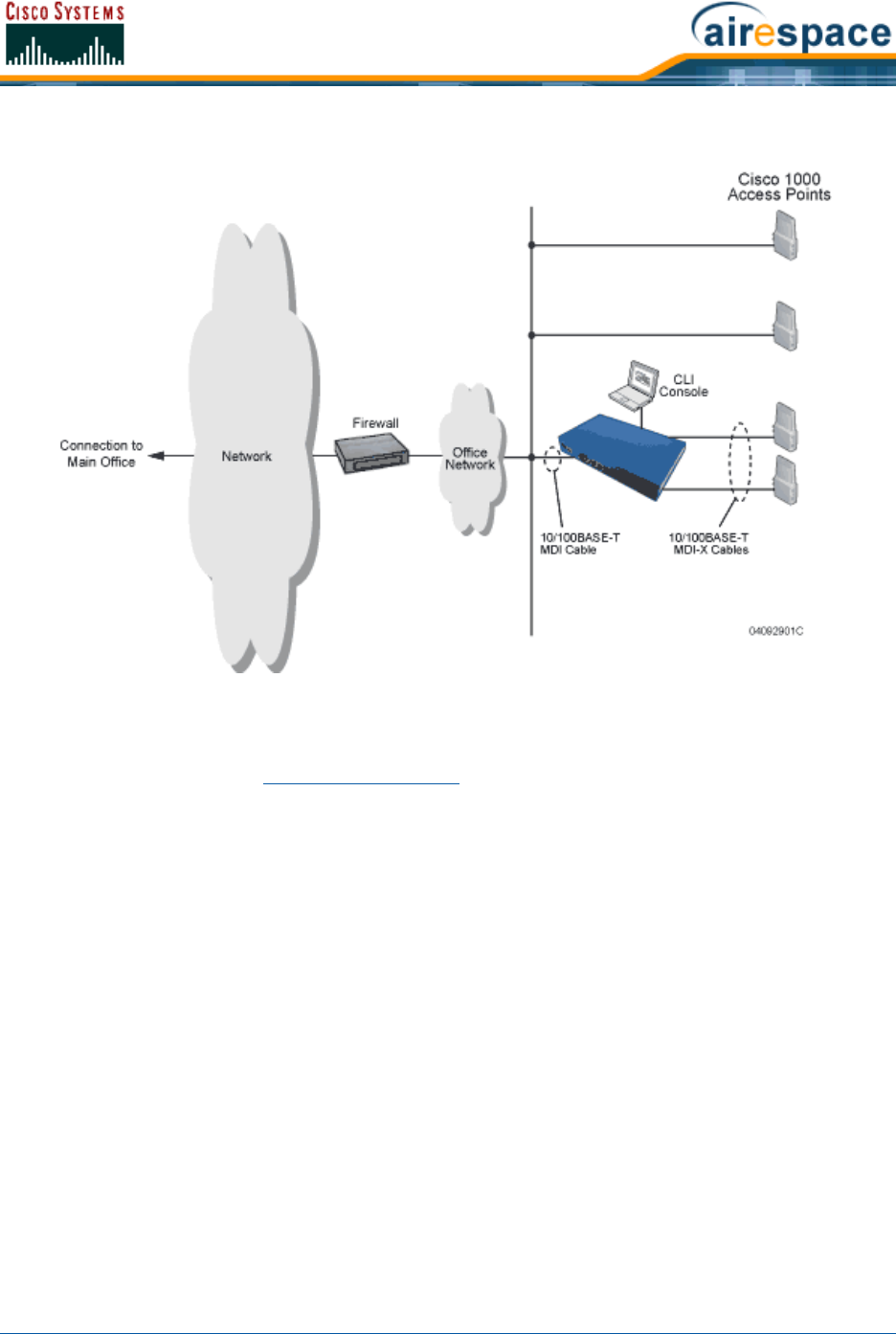
3/11/05 Cisco 4100 Series Wireless LAN Controllers
OL-7426-02
Figure - Physical Network Connections to the Cisco 2000 Series Wireless LAN Controller
Cisco 4100 Series Wireless LAN ControllersCisco 4100 Series Wireless LAN Controllers
Cisco 4100 Series Wireless LAN Controllers can communicate with the network through one or two
physical ports, and the logical Management Interface can be assigned to the one or two physical ports.
The physical port description follows:
•Two GigE 1000BASE-SX fiber-optic cables can plug into the LC connectors on the front of the
Cisco 4100 Series Wireless LAN Controller, and they must be connected to the same subnet.
Note that the two GigE ports are redundant--the first port that becomes active is the master,
and the second port becomes the backup port. If the first connection fails, the standby
connection becomes the master, and the failed connection becomes the backup port.
Note that the 1000BASE-SX circuits provides 100/1000 Mbps wired connections to the network
through 850nM (SX) fiber-optic links using LC physical connectors.
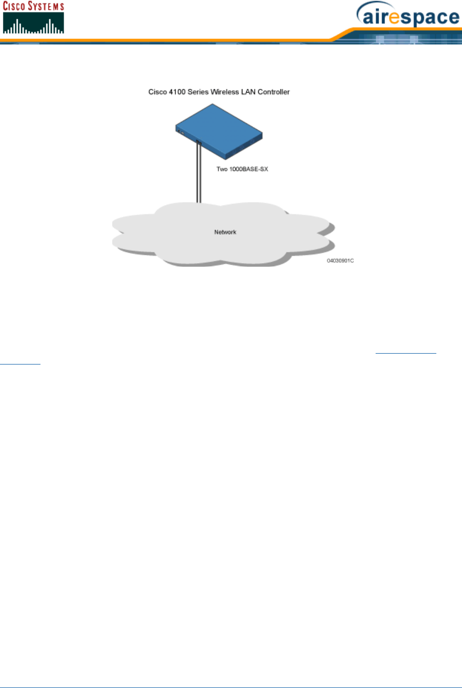
3/11/05 VPN/Enhanced Security Module
OL-7426-02
Figure - Physical Network Connections to the Cisco 4100 Series Wireless LAN Controller
VPN/Enhanced Security ModuleVPN/Enhanced Security Module
All Cisco 4100 Series Wireless LAN Controllers can be equipped with an optional VPN/Enhanced Security
Module (AS-Switch-ESM), which slides into the rear panel of the Cisco 4100 Series Wireless LAN
Controller. The VPN/Enhanced Security Module adds significant hardware encryption acceleration to the
Cisco 4100 Series Wireless LAN Controller, which enables the following through the Management
Interface:
•Sustain up to 1 Gbps throughput with Layer 2 and Layer 3 encryption enabled.
•Provide a built-in VPN server for mission-critical traffic.
•Support high-speed, processor-intensive encryption, such as L2TP, IPSec and 3DES.
The following figure shows the VPN/Enhanced Security Module sliding into the rear of a Cisco 4100
Series Wireless LAN Controller.
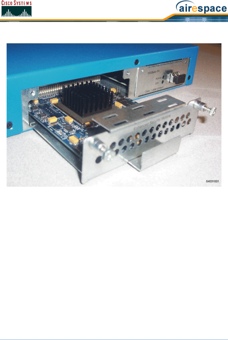
3/11/05 VPN/Enhanced Security Module
OL-7426-02
Figure - Cisco 4100 Series Wireless LAN Controller VPN/Enhanced Security Module Location
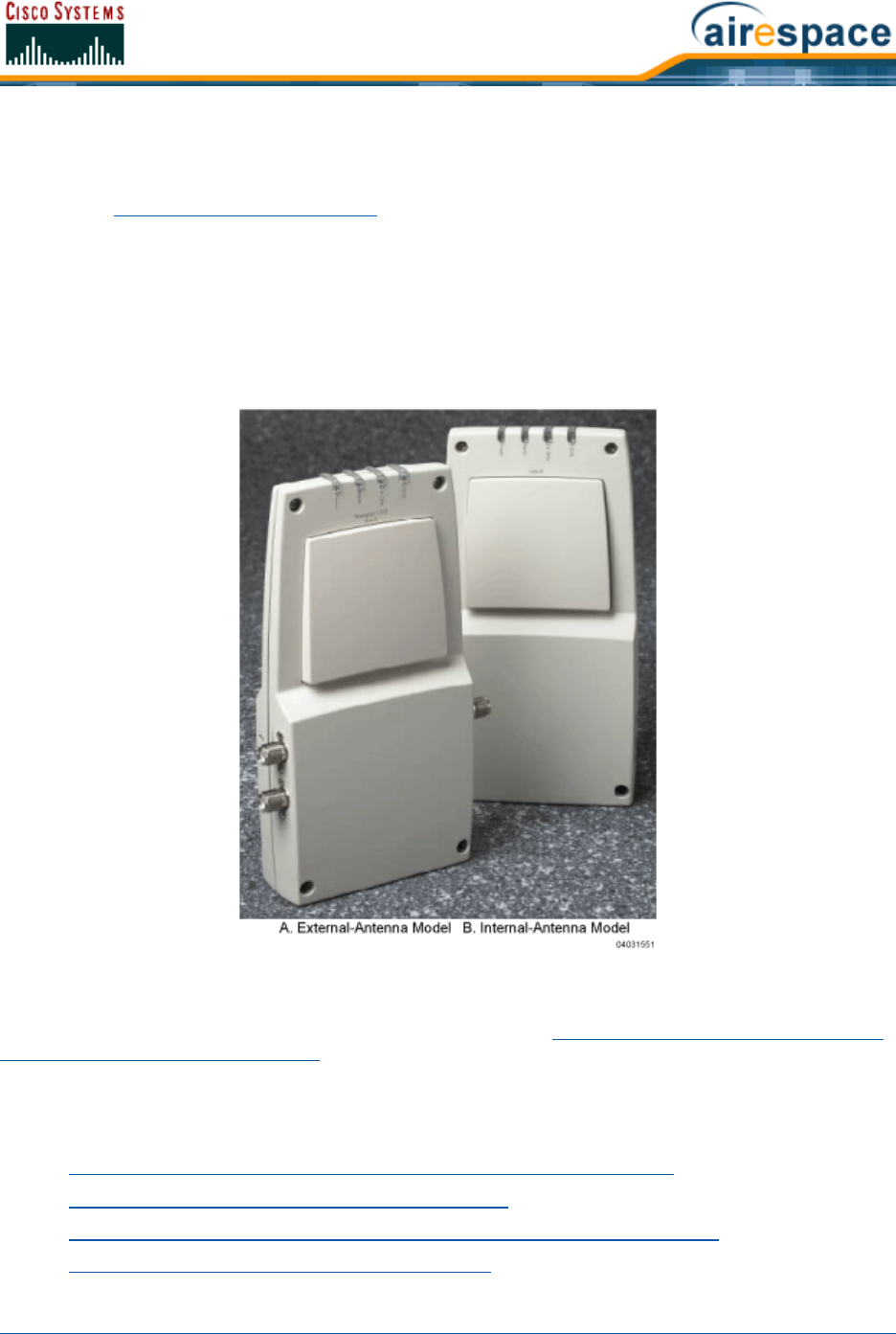
3/11/05 Cisco 1000 Series IEEE 802.11a/b/g Lightweight Access Points
OL-7426-02
About Cisco 1000 Series IEEE 802.11a/b/g Lightweight Access PointsCisco
1000 Series IEEE 802.11a/b/g Lightweight Access Points
The Cisco 1000 Series lightweight access point is a part of the innovative Product Guide. When associ-
ated with an Cisco Wireless LAN Controllers as described below, the Cisco 1000 Series lightweight
access point provides advanced 802.11a and/or 802.11b/g Access Point functions in a single aestheti-
cally pleasing plenum-rated enclosure. The following figure shows the two types of Cisco 1000 Series
lightweight access point: without and with connectors for external antennas.
Note that Cisco also offers Cisco 1030 remote edge lightweight access points, which are Cisco 1000
Series lightweight access points designed for remote deployment, Radio Resource Management (RRM)
control via a WAN link, and which includes connectors for external antennas.
Figure - Cisco 1000 Series Lightweight Access Point
Note that the Cisco 1000 Series lightweight access point is manufactured in a neutral color so it blends
into most environments (but can be painted), contains pairs of high-gain internal antennas for unidirec-
tional (180-degree) or omnidirectional (360-degree) coverage (Cisco 1000 Series Lightweight Access
Point External and Internal Antennas), and is plenum-rated for installations in hanging ceiling spaces.
In the Cisco SWAN, most of the processing responsibility is removed from traditional SOHO (small
office, home office) APs and resides in the Cisco Wireless LAN Controllers.
Refer to the following for more information on Cisco 1000 Series lightweight access points:
•Cisco 1030 IEEE 802.11a/b/g Remote Edge Lightweight Access Points
•Cisco 1000 Series Lightweight Access Point Models
•Cisco 1000 Series Lightweight Access Point External and Internal Antennas
•Cisco 1000 Series Lightweight Access Point LEDs

3/11/05 Cisco 1030 IEEE 802.11a/b/g Remote Edge Lightweight Access Points
OL-7426-02
•Cisco 1000 Series Lightweight Access Point Connectors
•Cisco 1000 Series Lightweight Access Point Power Requirements
•Cisco 1000 Series Lightweight Access Point External Power Supply
•Cisco 1000 Series Lightweight Access Point Mounting Options
•Cisco 1000 Series Lightweight Access Point Physical Security
•Cisco 1000 Series Lightweight Access Point Monitor Mode
•Cisco 1000 Series IEEE 802.11a/b/g Lightweight Access Point Deployment Guide
About Cisco 1030 IEEE 802.11a/b/g Remote Edge Lightweight Access PointsCisco 1030 IEEE 802.11a/b/g
Remote Edge Lightweight Access Points
The only exception to the general rule of Cisco 1000 Series IEEE 802.11a/b/g Lightweight Access Points
being continuously controlled by Cisco Wireless LAN Controllers is the Cisco 1000 Series Lightweight
Access Point (Cisco 1030 remote edge lightweight access point). The Cisco 1030 remote edge light-
weight access point is intended to be located at a remote site, initially configured by a Cisco Wireless
LAN Controller, and normally controlled by a Cisco Wireless LAN Controller.
However, because the Cisco 1030 remote edge lightweight access point bridges the client data
(compared with other Cisco 1000 Series lightweight access points, which pass all client data through
their respective Cisco Wireless LAN Controller), if the WAN link breaks between the Cisco 1030 remote
edge lightweight access point and its Cisco Wireless LAN Controller, the Cisco 1030 remote edge light-
weight access point continues transmitting WLAN 1 client data through other Cisco 1030 remote edge
lightweight access points on its local subnet. However, it cannot take advantage of features accessed
from the Cisco Wireless LAN Controller, such as establishing new VLANs, until communication is
reestablished.
The Cisco 1030 remote edge lightweight access point includes the traditional SOHO (small office, home
office) AP processing power, and thus can continue operating if the WAN link to its associated Cisco
Wireless LAN Controller fails. Because it is configured by its associated Cisco Wireless LAN Controller, it
has the same WLAN configuration as the rest of the Cisco SWAN (refer to Cisco SWAN WLANs). As long
as it remains connected to its Cisco Wireless LAN Controller, it varies its transmit power and channel
selection under control of the Radio Resource Management (RRM), and performs the same Rogue AP
location as any other Cisco 1000 Series lightweight access point.
Note that the Cisco 1030 remote edge lightweight access point can support multiple WLANs while it is
connected to its Cisco Wireless LAN Controller. However, when it loses connection to its Cisco Wireless
LAN Controller, it supports only one WLAN on its local subnet.
The following figure shows a typical Cisco 1030 remote edge lightweight access point configuration:
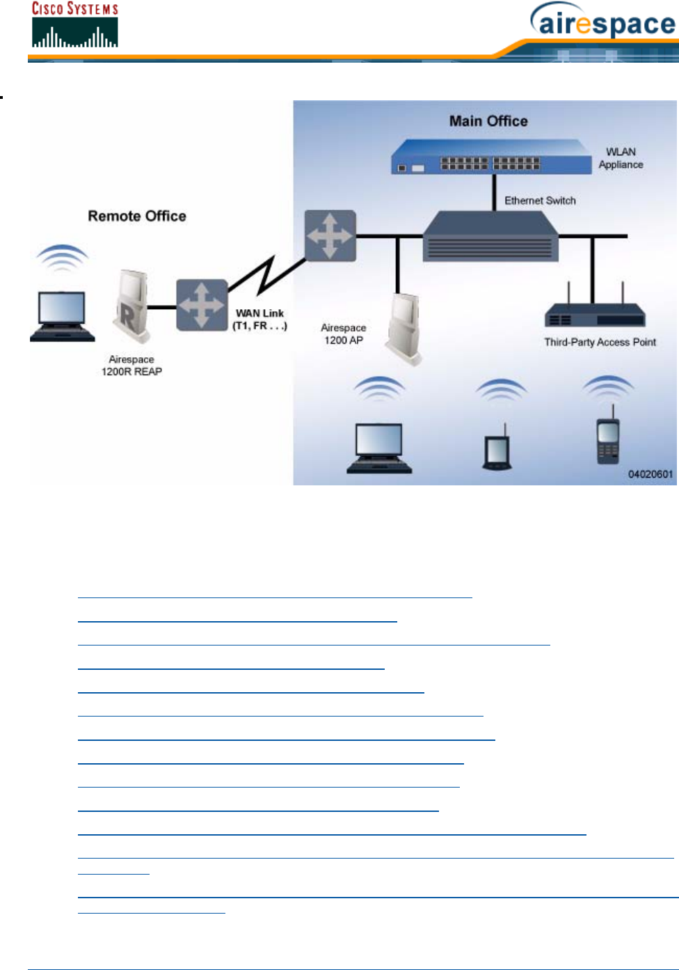
3/11/05 Cisco 1030 IEEE 802.11a/b/g Remote Edge Lightweight Access Points
OL-7426-02
Note that the Cisco 1030 remote edge lightweight access point must have a DHCP server available on
its local subnet, so it can obtain an IP address upon reboot. Also note that the Cisco 1030 remote edge
lightweight access points at each remote location must be on the same subnet to allow client roaming.
Refer to the following for more information on Cisco 1000 Series lightweight access points:
•Cisco 1000 Series IEEE 802.11a/b/g Lightweight Access Points
•Cisco 1000 Series Lightweight Access Point Models
•Cisco 1000 Series Lightweight Access Point External and Internal Antennas
•Cisco 1000 Series Lightweight Access Point LEDs
•Cisco 1000 Series Lightweight Access Point Connectors
•Cisco 1000 Series Lightweight Access Point Power Requirements
•Cisco 1000 Series Lightweight Access Point External Power Supply
•Cisco 1000 Series Lightweight Access Point Mounting Options
•Cisco 1000 Series Lightweight Access Point Physical Security
•Cisco 1000 Series Lightweight Access Point Monitor Mode
•Cisco 1000 Series IEEE 802.11a/b/g Lightweight Access Point Deployment Guide
•Internal-Antenna AP1010 Cisco 1000 Series IEEE 802.11a/b/g Lightweight Access Point Quick
Start Guide
•External-Antenna AP1020 and AP1030 Cisco 1000 Series IEEE 802.11a/b/g Lightweight Access
Point Quick Start Guide

3/11/05 Cisco 1000 Series Lightweight Access Point Models
OL-7426-02
About Cisco 1000 Series Lightweight Access Point ModelsCisco 1000 Series Lightweight Access Point Models
The Cisco 1000 Series lightweight access point includes one 802.11a and one 802.11b/g radio. The
Cisco 1000 Series lightweight access point is available in the following configurations:
•AIR-AP1010-A-K9, AIR-AP1010-C-K9, AIR-AP1010-E-K9, AIR-AP1010-J-K9, AIR-AP1010-N-K9,
and AIR-AP1010-S-K9 - AP1010 Cisco 1000 Series lightweight access point with one 802.11a
and one 802.11b/g radio and four high-gain internal antennas, one 5 GHz external antenna
adapter, and two 2.4 GHz external antenna adapters.
•AIR-AP1020-A-K9, AIR-AP1020-C-K9, AIR-AP1020-E-K9, AIR-AP1020-J-K9, AIR-AP1020-N-K9,
and AIR-AP1020-S-K9 - AP1020 Cisco 1000 Series lightweight access point with one 802.11a
and one 802.11b/g radio, four high-gain internal antennas, and no external antenna adapters.
•AIR-AP1030-A-K9, AIR-AP1030-C-K9, AIR-AP1030-E-K9, AIR-AP1030-J-K9, AIR-AP1030-N-K9,
and AIR-AP1030-S-K9 - AP1030 Cisco 1000 Series lightweight access point (Cisco 1030 remote
edge lightweight access point) with one 802.11a and one 802.11b/g radio and four high-gain
internal antennas, one 5 GHz external antenna adapter, and two 2.4 GHz external antenna
adapters.
The Cisco 1000 Series lightweight access point is shipped with a color-coordinated ceiling mount base
and hanging-ceiling rail clips. You can also order projection- and flush-mount sheet metal wall
mounting bracket kits. The base, clips, and optional brackets allow quick mounting to ceiling or wall.
The Cisco 1000 Series lightweight access point can be powered by Power Over Ethernet or by an Cisco
1000 Series Lightweight Access Point External Power Supply. The external power supply model is:
•AIR-PWR-1000 - Optional External 110-220 VAC-to-48 VDC Power Supply for any Cisco 1000
Series lightweight access point.
The Single Inline PoE injector model is:
•AIR-PWRINJ-1000AF - Optional Single 802.3af Inline Power over Ethernet Injector for any Cisco
1000 Series lightweight access point, powered by 90-250 VAC.
The projection and flush sheet metal wall mount bracket model is:
•AIR-ACC-WBRKT1000 - Optional sheet metal wall-mount bracket kit for any Cisco 1000 Series
lightweight access point. Includes one projection-mount and one flush-mount bracket per kit.
About Cisco 1000 Series Lightweight Access Point External and Internal Antennas
Cisco 1000 Series Lightweight Access Point External and Internal Antennas
The Cisco 1000 Series lightweight access point enclosure contains one 802.11a and/or one 802.11b/g
radio and four (two 802.11a and two 802.11b/g) high-gain antennas, which can be independently
enabled or disabled to produce a 180-degree sectorized or 360-degree omnidirectional coverage area.
Note that the wireless LAN operator can disable either one of each pair of the Cisco 1000 Series light-
weight access point internal antennas to produce a 180-degree sectorized coverage area. This feature
can be useful, for instance, for outside-wall mounting locations where coverage is only desired inside
the building, and in a back-to-back arrangement that can allow twice as many clients in a given area.
Note: Refer to Cisco SWAN Supported Country Codes for the most recent information
on supported Regulatory Domains.
Note: Cisco 1000 Series lightweight access points must use the factory-supplied
internal or external antennas to avoid violating FCC requirements and voiding the
user’s authority to operate the equipment. Refer to FCC Statements for Cisco 1000
Series Lightweight Access Points for detailed information.

3/11/05 Cisco 1000 Series Lightweight Access Point External and Internal Antennas
OL-7426-02
The following sections contain more information about Cisco 1000 Series lightweight access point
internal and external antennas:
•External Antenna Connectors
•Antenna Sectorization
•802.11a Internal Antenna Patterns
•802.11b/g Internal Antenna Patterns
External Antenna ConnectorsExternal Antenna Connectors
The AIR-AP1020-A-K9, AIR-AP1020-E-K9, AIR-AP1020-J-K9, AIR-AP1030-A-K9, AIR-AP1030-E-K9,
and AIR-AP1030-J-K9 Cisco 1000 Series lightweight access points have male reverse-polarity TNC
jacks for installations requiring factory-supplied external directional or high-gain antennas. The
external antenna option can create more flexibility in Cisco 1000 Series lightweight access point
antenna placement.
Note that the 802.11b/g 2.4 GHz Left external antenna connector is associated with the internal Side A
antenna, and that the 2.4 GHz Right external antenna connector is associated with the internal Side B
antenna. When you have 802.11b/g diversity enabled, the Left external or Side A internal antennas are
diverse from the Right external or Side B internal antennas.
Also note that the 802.11a 5 GHz Left external antenna connector is separate from the internal
antennas, and adds diversity to the 802.11a transmit and receive path. Note that no external 802.11a
antennas are certified in FCC-regulated areas, but external 802.11a antennas may be certified for use
in other countries.
Antenna SectorizationAntenna Sectorization
Note that the Cisco SWAN supports Antenna Sectorization, which can be used to increase the number of
clients and/or client throughput in a given air space. Installers can mount two Cisco 1000 Series light-
weight access points back-to-back, and the Network operator can disable the second antenna in both
Cisco 1000 Series lightweight access points to create a 360-degree coverage area with two sectors.
Installers can also mount Cisco 1000 Series lightweight access points on the periphery of a building and
disable the Side B internal antennas. This configuration can be used to supply service to the building
interior without extending coverage to the parking lot, at the cost of eliminating the internal antenna
diversity function.
802.11a Internal Antenna Patterns802.11a Internal Antenna Patterns
The Cisco 1000 Series lightweight access points contain one 802.11a radio, which drives two fully
enclosed high-gain antennas that provide a large 360-degree coverage area. The two internal antennas
are used at the same time to provide a 360-degree omnidirectional coverage area, or either antenna
can be disabled to provide a 180-degree sectorized coverage area.
When equipped with an optional factory-supplied external antenna, the 802.11a Cisco Radio supports
receive and transmit diversity between the internal antennas and the external antenna. The diversity
function provided by Cisco Radios can result in lower multipath fading, fewer packet retransmissions,
and higher client throughput.
Note: The AIR-AP1010-A-K9, AIR-AP1010-E-K9, and AIR-AP1010-J-K9 Cisco 1000
Series lightweight access points are designed to be used exclusively with the internal
high-gain antennas, and have no jacks for external antennas.
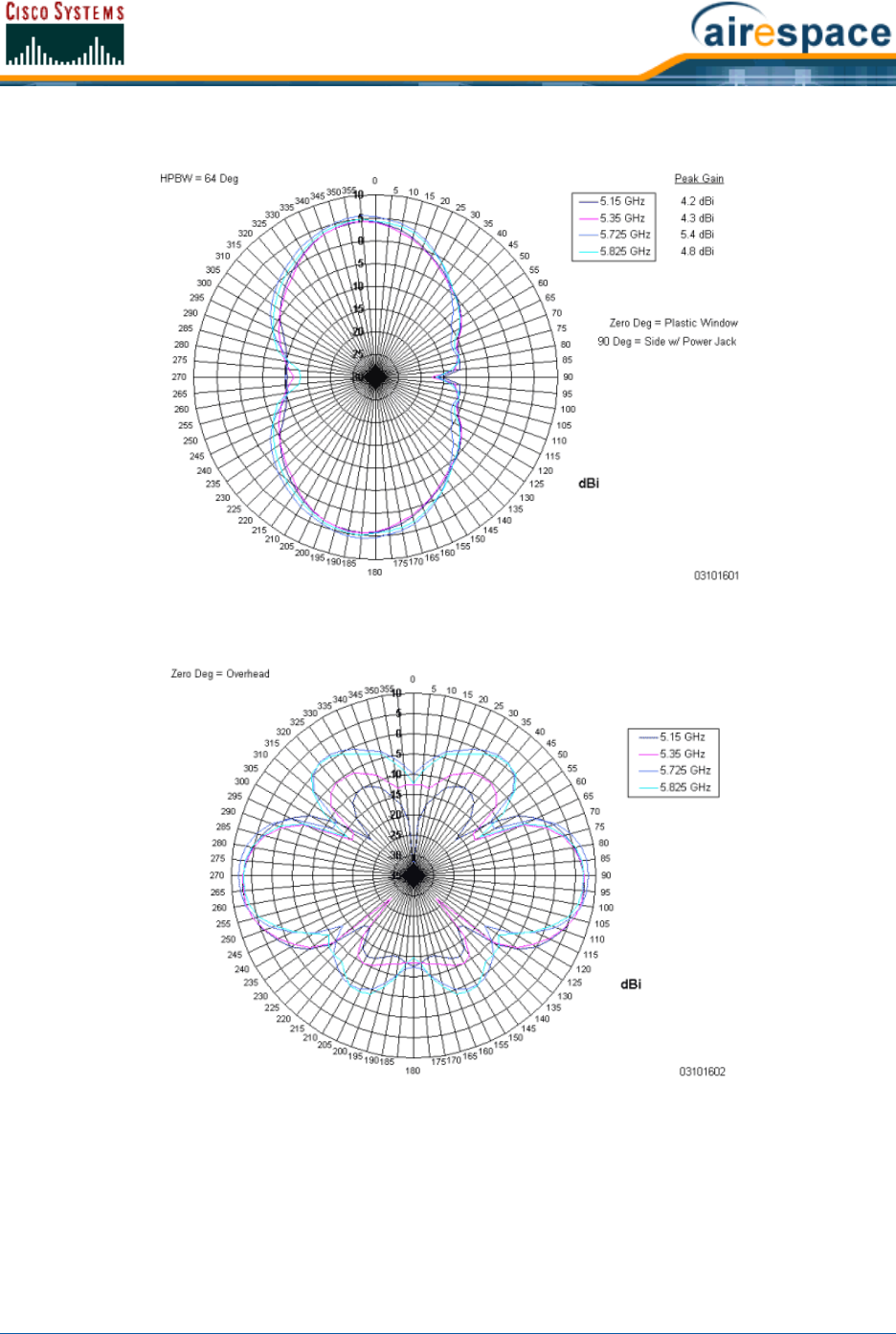
3/11/05 Cisco 1000 Series Lightweight Access Point External and Internal Antennas
OL-7426-02
Figure - Cisco 1000 Series Lightweight Access Point 802.11a OMNI (Dual Internal) Azimuth Antenna Gain Pattern
Figure - Cisco 1000 Series Lightweight Access Point 802.11a OMNI (Dual Internal) Elevation Antenna Gain Pattern
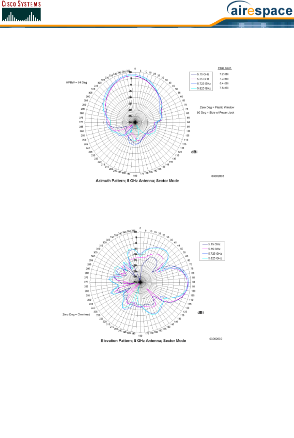
3/11/05 Cisco 1000 Series Lightweight Access Point External and Internal Antennas
OL-7426-02
Figure - Cisco 1000 Series Lightweight Access Point 802.11a Sectorized (Single Internal) Azimuth Antenna Gain
Pattern
Figure - Cisco 1000 Series Lightweight Access Point 802.11a Sectorized (Single Internal) Elevation Antenna Gain
Pattern
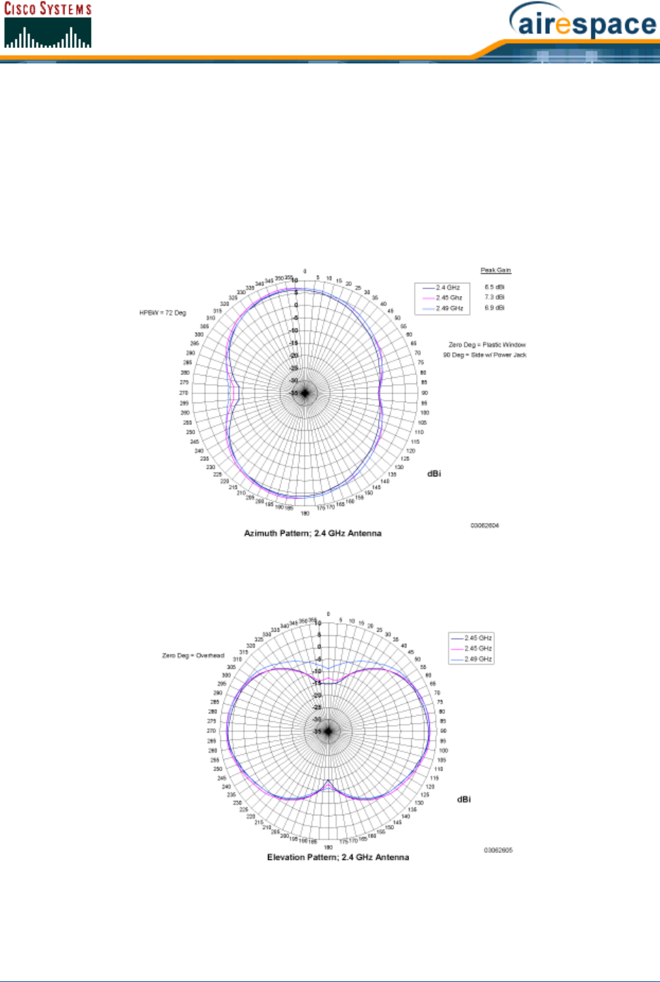
3/11/05 Cisco 1000 Series Lightweight Access Point External and Internal Antennas
OL-7426-02
802.11b/g Internal Antenna Patterns802.11b/g Internal Antenna Patterns
The Cisco 1000 Series lightweight access points contain one 802.11b/g radio which drives two fully
enclosed high-gain antennas which can provide a large 360-degree coverage area. The two internal
antennas can be used at the same time to provide a 360-degree omnidirectional coverage area, or
either antenna can be disabled to provide a 180-degrees sectorized coverage area.
The 802.11b/g Cisco Radios support receive and transmit diversity between the internal antennas and/
or optional factory-supplied external antennas.
Figure - Cisco 1000 Series Lightweight Access Point 802.11b/g OMNI (Dual Internal) Azimuth Antenna Gain Pattern
Figure - Cisco 1000 Series Lightweight Access Point 802.11b/g OMNI (Dual Internal) Elevation Antenna Gain Pattern
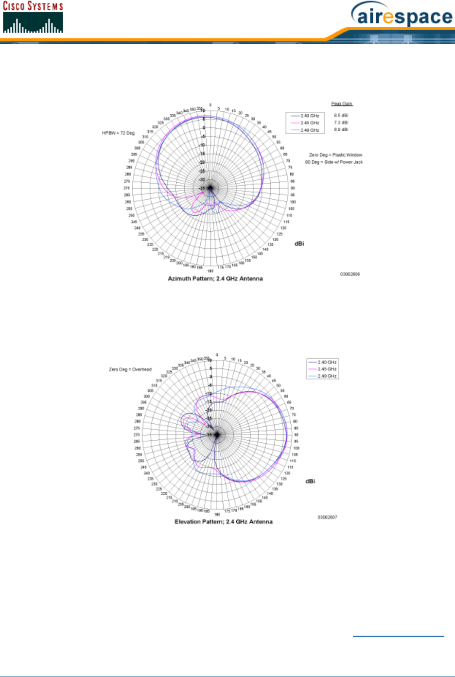
3/11/05 Cisco 1000 Series Lightweight Access Point LEDs
OL-7426-02
Figure - Cisco 1000 Series Lightweight Access Point 802.11b/g Sectorized (Single Internal) Azimuth Antenna Gain
Pattern
Figure - Cisco 1000 Series Lightweight Access Point 802.11b/g Sectorized (Single Internal) Elevation Antenna Gain
Pattern
About Cisco 1000 Series Lightweight Access Point LEDsCisco 1000 Series Lightweight Access Point LEDs
Each Cisco 1000 Series lightweight access point is equipped with four LEDs across the top of the case.
They can be viewed from nearly any angle. The LEDs indicate power and fault status, 2.4 GHz
(802.11b/g) Cisco Radio activity, and 5 GHz (802.11a) Cisco Radio activity.
This LED display allows the wireless LAN manager to quickly monitor the Cisco 1000 Series lightweight
access point status. For more detailed troubleshooting instructions, refer to the Troubleshooting Tips
section.
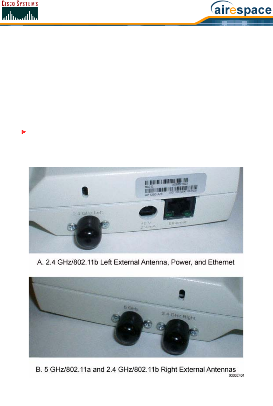
3/11/05 Cisco 1000 Series Lightweight Access Point Connectors
OL-7426-02
About Cisco 1000 Series Lightweight Access Point ConnectorsCisco 1000 Series Lightweight Access Point Connectors
The AIR-AP1020-A-K9, AIR-AP1020-E-K9, AIR-AP1020-J-K9, AIR-AP1030-A-K9, AIR-AP1030-E-K9,
and AIR-AP1030-J-K9 Cisco 1000 Series lightweight access points have the following external
connectors:
•One RJ-45 Ethernet jack, used for connecting the Cisco 1000 Series lightweight access point to
the network.
•One 48 VDC power input jack, used to plug in an optional factory-supplied external power
adapter.
•Three male reverse-polarity TNC antenna jacks, used to plug optional external antennas into
the Cisco 1000 Series lightweight access point: two for an 802.11b/g radio, and one for an
802.11a radio.
Figure - Cisco 1000 Series Lightweight Access Point External Antenna Connectors
Note: The AIR-AP1010-A-K9, AIR-AP1010-E-K9, and AIR-AP1010-J-K9 Cisco 1000
Series lightweight access points are designed to be used exclusively with the internal
high-gain antennas, and have no jacks for external antennas.

3/11/05 Cisco 1000 Series Lightweight Access Point Power Requirements
OL-7426-02
Note that the Cisco 1000 Series lightweight access point can receive power over the CAT-5 cable from
network equipment. Refer to Power Over Ethernet for more information about this option.
The Cisco 1000 Series lightweight access point can be powered from an optional factory-supplied
external AC-to-48 VDC power adapter. If you are powering the Cisco 1000 Series lightweight access
point using an external adapter, plug the adapter into the 48 VDC power jack on the side of the Cisco
1000 Series lightweight access point.
The Cisco 1000 Series lightweight access point includes two 802.11a and two 802.11b/g high-gain
internal antennas, which provide omnidirectional coverage. However, some Cisco 1000 Series light-
weight access point models and the Cisco 1030 remote edge lightweight access point can also use
optional factory-supplied external high-gain and/or directional antennas, as described in Cisco 1000
Series Lightweight Access Point External and Internal Antennas. When you are using external antennas,
plug them into the male reverse-polarity TNC jacks on the side of the AIR-AP1020-A-K9,
AIR-AP1020-E-K9, AIR-AP1020-J-K9, AIR-AP1030-A-K9, AIR-AP1030-E-K9, and AIR-AP1030-J-K9
Cisco 1000 Series lightweight access points as described in the Internal-Antenna AP1010 Cisco 1000
Series IEEE 802.11a/b/g Lightweight Access Point Quick Start Guide.
About Cisco 1000 Series Lightweight Access Point Power RequirementsCisco 1000 Series Lightweight Access Point Power
Requirements
Each Cisco 1000 Series lightweight access point requires a 48 VDC nominal (between 38 and 57 VDC)
power source capable of providing 7 Watts. The polarity of the DC source does not matter because the
Cisco 1000 Series lightweight access point can use either a +48 VDC or a -48 VDC nominal source.
Cisco 1000 Series lightweight access points can receive power from the Cisco 1000 Series Lightweight
Access Point External Power Supply (which draws power from a 110-220 VAC electrical outlet) plugged
into the side of the Cisco 1000 Series lightweight access point case, or from Power Over Ethernet.
Note: The Cisco 1000 Series lightweight access points must use the factory-supplied
internal or external antennas to avoid violating FCC regulations and voiding the
user’s authority to operate the equipment, as described in FCC Statements for Cisco
1000 Series Lightweight Access Points.

3/11/05 Cisco 1000 Series Lightweight Access Point External Power Supply
OL-7426-02
Figure - Typical Cisco 1000 Series Lightweight Access Point External Power Supply
For more information about the Cisco 1000 Series lightweight access point specifications and capacities,
refer to Specifications, available in the Cisco SWAN Marketing Literature.
About Cisco 1000 Series Lightweight Access Point External Power SupplyCisco 1000 Series Lightweight Access Point
External Power Supply
The Cisco 1000 Series lightweight access point can receive power from an external
110-220 VAC-to-48 VDC power supply or from Power Over Ethernet equipment.
The external power supply (AS-AP-PWR) plugs into a secure 110 through 220 VAC electrical outlet. The
converter produces the required 48 VDC output (Cisco 1000 Series Lightweight Access Point Power
Requirements) for the Cisco 1000 Series lightweight access point. The converter output feeds into the
side of the Cisco 1000 Series lightweight access point through a 48 VDC jack (Cisco 1000 Series Light-
weight Access Point Connectors).
Note that the AS-AP-PWR external power supply can be ordered with country-specific electrical outlet
power cords. Contact Cisco when ordering to receive the correct power cord.
About Cisco 1000 Series Lightweight Access Point Mounting OptionsCisco 1000 Series Lightweight Access Point Mounting Options
Refer to the Internal-Antenna AP1010 Cisco 1000 Series IEEE 802.11a/b/g Lightweight Access Point
Quick Start Guide for the Cisco 1000 Series lightweight access point mounting options.
About Cisco 1000 Series Lightweight Access Point Physical SecurityCisco 1000 Series Lightweight Access Point Physical Security
The side of the Cisco 1000 Series lightweight access point housing includes a slot for a Kensington
MicroSaver Security Cable. You can use any MicroSaver Security Cable to ensure that your Cisco 1000
Series lightweight access point stays where you mounted it!
Refer to the Kensington website for more information about their security products, or to the
Internal-Antenna AP1010 Cisco 1000 Series IEEE 802.11a/b/g Lightweight Access Point Quick Start
Guide for installation instructions.

3/11/05 Cisco 1000 Series Lightweight Access Point Monitor Mode
OL-7426-02
About Cisco 1000 Series Lightweight Access Point Monitor ModeCisco 1000 Series Lightweight Access Point Monitor Mode
The Cisco 1000 Series lightweight access points and Cisco Wireless LAN Controllers are capable of
performing Rogue AP detection and containment while providing regular service. The Rogue AP
detection is performed across all 801.11 channels, regardless of the Country Code selected. (Refer to
Cisco SWAN Supported Country Codes for more details).
However, if the administrator would prefer to dedicate specific Cisco 1000 Series lightweight access
points to Rogue AP detection and containment, the Monitor mode should be enabled for individual Cisco
1000 Series lightweight access points.
The Monitor function is set for all 802.11 Cisco Radios on a per-Cisco 1000 Series lightweight access
point basis in the Cisco APs > Details section in the Web User Interface Online Help.

3/11/05 Rogue Access Points
OL-7426-02
About Rogue Access PointsRogue Access Points
Because they are inexpensive and readily available, employees are plugging unauthorized rogue access
points (Rogue APs) into existing LANs and building ad hoc wireless networks without IT department
knowledge or consent.
These Rogue APs can be a serious breach of network security, because they can be plugged into a
network port behind the corporate firewall. Because employees generally do not enable any security
settings on the Rogue APs, it is easy for unauthorized users to use the access point to intercept network
traffic and hijack client sessions. Even more alarming, wireless users and war chalkers frequently
publish unsecure access point locations, increasing the odds of having the enterprise security breached.
Rather than using a person with a scanner to manually detect Rogue APs, the Cisco SWAN automati-
cally collects information on Rogue APs detected by its managed Cisco 1000 Series IEEE 802.11a/b/g
Lightweight Access Points, by MAC and IP Address, and allows the Network operator to locate, tag and
monitor them as described in the Detecting and Locating Rogue Access Points section. The Operating
System can also be used to discourage Rogue AP clients by sending them deauthenticate and disasso-
ciate messages from one to four Cisco 1000 Series lightweight access points. Finally, the Operating
System can be used to automatically discourage all clients attempting to authenticate with all
Rogue APs on the enterprise subnet. Because this real-time detection is automated, it saves labor costs
used for detecting and monitoring Rogue APs while vastly improving LAN security.
Note that the peer-to-peer, or ad-hoc, clients can also be considered Rogue APs.
See also Rogue AP Location, Tagging and Containment.
Rogue AP Location, Tagging and ContainmentRogue AP Location, Tagging and Containment
This built-in detection, tagging, monitoring and containment capability allows system administrators to
take required actions:
•Locate Rogue APs as described in Detecting and Locating Rogue Access Points.
•Receive new Rogue AP notifications, eliminating hallway scans.
•Monitor unknown Rogue APs until they are eliminated or acknowledged.
•Determine the closest authorized Cisco 1000 Series IEEE 802.11a/b/g Lightweight Access
Points, making directed scans faster and more effective.
•Contain Rogue APs by sending their clients deauthenticate and disassociate messages from one
to four Cisco 1000 Series lightweight access points. This containment can be done for individual
Rogue APs by MAC address, or can be mandated for all Rogue APs connected to the enterprise
subnet.
•Tag Rogue APs:
-Acknowledge Rogue APs when they are outside of the LAN and do not compromise the
LAN or WLAN security.
-Accept Rogue APs when they do not compromise the LAN or WLAN security.
-Tag Rogue APs as unknown until they are eliminated or acknowledged.
-Tag Rogue APs as contained and discourage clients from associating with the Rogue AP
by having between one and four Cisco 1000 Series lightweight access points transmit
deauthenticate and disassociate messages to all Rogue AP clients. This function
contains all active channels on the same Rogue AP.
Rogue Detector mode detects whether or not a rogue is on a trusted network. It does not provide RF
service of any kind, but rather receives periodic rogue reports from the switch, and sniffs all ARP
packets. If it finds a match between an ARP request and a MAC address it receives from the switch, it
generates a rogue alert to the switch.

3/11/05 Rogue AP Location, Tagging and Containment
OL-7426-02
To facilitate automated Rogue AP detection in a crowded RF space, Cisco 1000 Series lightweight
access points can be configured to operate in Cisco 1000 Series Lightweight Access Point Monitor Mode,
allowing monitoring without creating unnecessary interference.

3/11/05 Cisco Wireless Control System
OL-7426-02
About the Cisco Wireless Control SystemCisco Wireless Control System
The Cisco Wireless Control System (Cisco WCS) is the Cisco Structured Wireless-Aware Network
network management tool that adds to the capabilities of the Web User Interface and the Command
Line Interface, moving from individual Cisco Wireless LAN Controllers to a network of Cisco Wireless
LAN Controllers. The Cisco Wireless Control System runs on Windows 2000, Windows 2003, and Red
Hat Enterprise Linux ES Server workstations.
The Cisco WCS includes the same configuration, performance monitoring, security, fault management,
and accounting options available at the Cisco Wireless LAN Controller level, but adds a graphical view of
multiple Cisco Wireless LAN Controllers and managed Cisco 1000 Series lightweight access points.
The Cisco WCS consists of Cisco WCS modules which support different feature levels:
•Cisco Wireless Control System, which includes wireless client data access, Rogue AP
containment functions, Cisco SWAN monitoring and control, and which allows Client and
Rogue AP location to the nearest Cisco 1000 Series lightweight access point.
•Cisco Wireless Control System with Location Services, which performs the same functions as
the Cisco Wireless Control System, and which allows high-accuracy Rogue AP and client
location to within 10 meters.
These features are listed in the following table:
Features
Cisco
WCS
Base
Software
Cisco
WCS
Location
Software
Location and Tracking:
• Low-Resolution Client Location Yes -
• High-Resolution Client Location - Yes
• Low-Resolution Rogue AP Location Yes -
• High-Resolution Rogue AP Location - Yes
Client Data Services, Security and Monitoring:
• Client Access via Cisco 1000 Series lightweight access points Yes Yes
• Multiple WLANs (Individual SSIDs and Policies) Yes Yes
Rogue AP Detecting and Containing using Cisco 1000 Series lightweight
access points Yes Yes
802.11a/b/g Bands Yes Yes
Radio Resource Management (RRM) (real-time assigning channels, and
detecting and containing rogue APs) Yes Yes
Radio Resource Management (RRM) (real-time detecting and avoiding
interference, controlling transmit power, assigning channels, managing
client mobility, distributing client load, and detecting coverage holes) Yes Yes
Automated Software and Configuration Updates Yes Yes
Wireless Intrusion Protection Yes Yes

3/11/05 Cisco Wireless Control System
OL-7426-02
The Cisco Wireless Control System runs on Windows 2000 or 2003 and Red Hat Enterprise Linux ES
Server workstations. The Windows Cisco WCS can run as a normal Windows application, or can be
installed as a service, which runs continuously and resumes running after a reboot. The Linux Cisco
WCS always runs as a normal Linux application.
The Cisco WCS User Interface allows Network operators to control all permitted Cisco SWAN configura-
tion, monitoring, and control functions through Internet Explorer 6.0 on a Windows workstation (or
other) web browser window. The Network operator permissions are defined by the Cisco WCS adminis-
trator in the Cisco WCS User Interface using the Cisco WCS User Interface Admin tab, which allows the
Cisco WCS administrator to administer user accounts and schedule periodic maintenance tasks.
Cisco WCS simplifies Cisco Wireless LAN Controller configuring and monitoring while decreasing data
entry errors with the Cisco Wireless LAN Controller Autodiscovery algorithm. The Cisco WCS uses
industry-standard SNMP protocol to communicate with Cisco Wireless LAN Controllers.
About the Cisco Wireless Control SystemCisco Wireless Control System
The Cisco Wireless Control System supports wireless client data access, Rogue AP detection and
containment functions, Cisco SWAN monitoring and control, and includes graphical views of the
following:
•Auto-discovery of Cisco 1000 Series IEEE 802.11a/b/g Lightweight Access Points as they
associate with Cisco Wireless LAN Controllers.
•Auto-discovery, and containment or notification of Rogue Access Points.
•Map-based organization of Access Point coverage areas, helpful when the enterprise spans
more than one geographical area. (Refer to Using Cisco WCS and Checking the Cisco SWAN
Network Summary.)
•User-supplied Campus, Building and Floor graphics, which show the following:
-Locations and status of managed access points. (Refer to Adding a Cisco Wireless LAN
Controller to Cisco WCS.)
-Locations of Rogue APs, based on signal strength received by nearest managed Cisco
1000 Series lightweight access points. (Refer to Detecting and Locating Rogue Access
Points.)
-Coverage hole alarm information for Cisco 1000 Series lightweight access points is
based on received signal strength from clients. This information appears in a tabular
rather than map format. (Refer to Finding Coverage Holes.)
-RF coverage maps.
•System-wide control:
Global and Individual AP Security Policies Yes Yes
Monitors and Configures Cisco Wireless LAN Controllers Yes Yes
Supported Workstations:
• Windows 2000 or Windows 2003 Yes Yes
• Red Hat Enterprise Linux ES Server Yes Yes
Features
Cisco
WCS
Base
Software
Cisco
WCS
Location
Software

3/11/05 Cisco Wireless Control System with Location Services
OL-7426-02
-Network, Cisco Wireless LAN Controller, and managed Cisco 1000 Series lightweight
access point configuration is streamlined using customer-defined templates.
-Network, Cisco Wireless LAN Controller, and managed Cisco 1000 Series lightweight
access point status and alarm monitoring.
-Automated and manual data client monitoring and control functions.
-Automated monitoring: Rogue APs, coverage holes, security violations, Cisco Wireless
LAN Controllers, and Cisco 1000 Series lightweight access points.
-Full event logs available for data clients, Rogue APs, coverage holes, security violations,
Cisco Wireless LAN Controllers, and Cisco 1000 Series lightweight access points.
-Automatic channel and power level assignment by Radio Resource Management (RRM).
-User-defined automatic Cisco Wireless LAN Controller status audits, missed trap polling,
configuration backups, and policy cleanups.
•Real-time location of Rogue APs to the nearest Cisco 1000 Series lightweight access point.
•Real-time and historical location of clients to the nearest Cisco 1000 Series lightweight access
point.
•Runs on Windows 2000 or 2003 and Red Hat Enterprise Linux ES Server workstations.
About the Cisco Wireless Control System with Location ServicesCisco Wireless Control System with Location Services
In addition to the graphical representations shown in the Cisco Wireless Control System, Cisco Wireless
Control System with Location Services adds the following enhancements:
•Real-time location of Rogue APs to within 10 meters.
•Real-time and historical location of clients to within 10 meters.
•Runs on Windows 2000 or 2003 and Red Hat Enterprise Linux ES Server workstations.
About the Cisco WCS User InterfaceCisco WCS User Interface
The Cisco WCS User Interface allows the Network operator to create and configure Cisco SWAN
coverage area layouts, configure system operating parameters, monitor real-time Cisco SWAN opera-
tion, and perform troubleshooting tasks using a standard HTTP or HTTPS Web Browser window. The
Cisco WCS User Interface also allows the Network operator to create, modify and delete user accounts,
change passwords, assign permissions, and schedule periodic maintenance tasks.
Cisco recommends Internet Explorer 6.0 or later on a Windows workstation Web Browser for full access
to the Cisco WCS functionality.
The Network operator creates new usernames passwords and assigns them to predefined permissions
groups. This task is described in Managing Cisco WCS and Database.
Network operators perform their tasks as described in Using the Cisco Wireless Control System.
About Cisco Wireless LAN Controller AutodiscoveryCisco Wireless LAN Controller Autodiscovery
Manually adding Cisco Wireless LAN Controller data to a management database can be time consuming,
and is susceptible to data entry errors. The Cisco Wireless Control System (Cisco WCS) includes a
Note: The HTTPS (SSL over HTTP) interface is enabled by default, and the HTTP
interface can be manually activated in the Command Line Interface, Web User
Interface and Cisco WCS User Interface.

3/11/05 Cisco WCS Alarm Email Notification
OL-7426-02
built-in Cisco Wireless LAN Controller configuration upload function that speeds up database creation
while eliminating errors.
Cisco Wireless LAN Controller Autodiscovery is limited to the Controller Mobility Group subnets defined
by the Network operator.
As Cisco 1000 Series lightweight access points associate with Cisco Wireless LAN Controllers, each
Cisco Wireless LAN Controller immediately transmits the Cisco 1000 Series lightweight access point
information to the Cisco Wireless Control System, which automatically adds the Cisco 1000 Series light-
weight access point to the Cisco WCS database.
After the Cisco 1000 Series lightweight access point information is in the Cisco WCS database,
operators can add the Cisco 1000 Series lightweight access point to the appropriate spot on a Cisco
WCS Interface map using Adding APs to Floor Plan and Open Area Maps, so the topological map of the
air space remains current.
About Cisco WCS Alarm Email NotificationCisco WCS Alarm Email Notification
The Cisco Wireless Control System (Cisco WCS) includes a built-in email notification function, which can
notify Network operators when Critical alarms occur.
Refer to the Cisco WCS Monitor All Alarms > Email Notification page to view the current alarm notifica-
tion settings.
About Cisco WCS Location CalibrationCisco WCS Location Calibration
The Cisco Wireless Control System (Cisco WCS) includes a calibration tool which allows Network
operators to accurately measure actual signal strength and attenuation in RF coverage areas, which
creates an accurate calibration model in the Cisco WCS database. This calibration model allows more
precise client and rogue AP location after calibration is completed. To save effort, the calibration model
can also be reused as a template for areas with an identical Cisco 1000 Series lightweight access point
layout and identical wall layout.
The calibration tool is used much like a site survey tool, and allows a technician to take a Cisco
WCS-equipped laptop to multiple locations on a floor or outdoor area and measure actual signal
strength at selected locations on the floor or outdoor area map. The technician then uses the calibration
tool in Cisco WCS to process the collected data points for the floor or outdoor area.
Refer to the Cisco WCS Monitor RF Calibration Models page to view the current calibration models.

3/11/05 Web User Interface
OL-7426-02
About the Web User InterfaceWeb User Interface
The Web User Interface is built into each Cisco Wireless LAN Controller. The Web User Interface allows
up to five users to simultaneously browse into the built-in Cisco Wireless LAN Controller http/https (http
+ SSL) Web server, configure parameters, and monitor operational status for the Cisco Wireless LAN
Controller and its associated access points.
Because the Web User Interface works with one Cisco Wireless LAN Controller at a time, the Web User
Interface is especially useful when you wish to configure or monitor a single Cisco Wireless LAN
Controller.
Refer to Using the Web User Interface for more information on the Web User Interface.
Note: Cisco strongly recommends that you enable the https: and disable the http:
interfaces to ensure more robust security for your Cisco SWAN.
Note: Some popup window filters can be configured to block the Web User Interface
Online Help windows. If your system cannot display the Online Help windows, disable
or reconfigure your browser popup filter software.

3/11/05 Command Line Interface
OL-7426-02
About the Command Line InterfaceCommand Line Interface
The Cisco Command Line Interface (CLI) is built into the Cisco Wireless LAN Controllers, and is one of
the Operating System user interfaces described in About the Cisco Structured Wireless-Aware Network.
The CLI allows operators to use a VT-100 emulator to locally or remotely configure, monitor and control
individual Cisco Wireless LAN Controllers, and to access extensive debugging capabilities.
Because the CLI works with one Cisco Wireless LAN Controller at a time, the Command Line Interface is
especially useful when you wish to configure or monitor a single Cisco Wireless LAN Controller.
The Cisco Wireless LAN Controller and its associated Cisco 1000 Series lightweight access points can be
configured and monitored using the Command Line Interface (CLI), which consists of a simple
text-based, tree-structured interface that allows up to five users with Telnet-capable terminal
emulators to simultaneously configure and monitor all aspects of the Cisco Wireless LAN Controller and
associated Cisco 1000 Series lightweight access points.
Refer to Using the Cisco SWAN CLI and the Cisco SWAN CLI Reference for more information.

3/11/05 Notes
OL-7426-02
Notes:Notes

4/1/05 © 2005 All Rights Reserved.
OL-7426-02
SOLUTIONSSOLUTIONS
•Operating System Security
•Converting a Cisco SWAN from Layer 2 to Layer 3 Mode
•Converting a Cisco SWAN from Layer 3 to Layer 2 Mode
•Configuring a Firewall for Cisco WCS
•Configuring the System for SpectraLink NetLink Telephones
•Management over Wireless
•Configuring a WLAN for a DHCP Server
•Customizing the Web Auth Login Screen
•Configuring Identity Networking for Operating System 2.2

4/1/05 Operating System Security
OL-7426-02
Operating System SecurityOperating System Security
Operating System Security includes the following sections:
•Overview
•Layer 1 Solutions
•Layer 2 Solutions
•Layer 3 Solutions
•Single Point of Configuration Policy Manager Solutions
•Rogue Access Point Solutions
•Integrated Security Solutions
•Simple, Cost-Effective Solutions
OverviewOverview
The industry-leading Operating System Security solution bundles potentially complicated Layer 1,
Layer 2 and Layer 3 802.11 Access Point security components into a simple policy manager that
customizes system-wide security policies on a per-WLAN basis (Operating System Security). Unlike
SOHO (small office, home office) 802.11 products, the Operating System Security solution included in
the Cisco Structured Wireless-Aware Network (Cisco SWAN) provides simpler, unified, and systematic
security management tools.
One of the biggest hurdles to WLAN deployment in the enterprise is the WEP (Wired Equivalent Privacy)
encryption, which has proven to be a weak standalone encryption method. A newer problem is the
availability of low-cost APs, which can be connected to the enterprise network and used to mount
‘man-in-the-middle’ and denial-of-service attacks. Also, the complexity of add-on security solutions has
prevented many IT managers from embracing the new 802.11 benefits. Finally, the 802.11 security
configuration and management cost has been daunting for resource-bound IT departments.
Layer 1 SolutionsLayer 1 Solutions
The Operating System Security solution ensures that all clients gain access within an operator-set
number of attempts. Should a client fail to gain access within that limit, it is automatically excluded
(blocked from access) until the operator-set timer expires. The Operating System can also disable SSID
broadcasts on a per-WLAN basis.
Layer 2 SolutionsLayer 2 Solutions
If a higher level of security and encryption is required, the network administrator can also implement
industry-standard security solutions, such as: 802.1X dynamic keys with EAP (extensible authentication
protocol), or WPA (Wi-Fi protected access) dynamic keys. The Cisco SWAN WPA implementation
includes AES (advanced encryption standard), TKIP + Michael (temporal key integrity protocol +
message integrity code checksum) dynamic keys, or WEP (Wired Equivalent Privacy) static keys.
Disabling is also used to automatically block Layer 2 access after an operator-set number of failed
authentication attempts.
Regardless of the wireless security solution selected, all Layer 2 wired communications between Cisco
Wireless LAN Controllers and Cisco 1000 Series lightweight access points are secured by passing data
through IPSec tunnels.

4/1/05 Operating System Security
OL-7426-02
Layer 3 SolutionsLayer 3 Solutions
The WEP problem can be further solved using industry-standard Layer 3 security solutions, such as
VPNs (virtual private networks), L2TP (Layer Two Tunneling Protocol), and IPSec (IP security) proto-
cols. The Cisco SWAN L2TP implementation includes IPsec, and the IPSec implementation includes IKE
(internet key exchange), DH (Diffie-Hellman) groups, and three optional levels of encryption: DES
(ANSI X.3.92 data encryption standard), 3DES (ANSI X9.52-1998 data encryption standard), or AES/
CBC (advanced encryption standard/cipher block chaining). Disabling is also used to automatically
block Layer 3 access after an operator-set number of failed authentication attempts.
The Cisco SWAN IPSec implementation also includes industry-standard authentication using: MD5
(message digest algorithm), or SHA-1 (secure hash algorithm-1).
The Cisco SWAN supports local and RADIUS MAC (media access control) filtering. This filtering is best
suited to smaller client groups with a known list of 802.11 access card MAC addresses.
Finally, the Cisco SWAN supports local and RADIUS user/password authentication. This authentication
is best suited to small to medium client groups.
Single Point of Configuration Policy Manager SolutionsSingle Point of Configuration Policy Manager Solutions
When the Cisco SWAN is equipped with Cisco Wireless Control System, you can configure system-wide
security policies on a per-WLAN basis. SOHO access points force you to individually configure security
policies on each AP, or use a third-party appliance to configure security policies across multiple APs.
Because the Cisco SWAN security policies can be applied across the whole system from the Cisco
Wireless Control System, errors can be eliminated and the overall effort is greatly reduced.
Rogue Access Point SolutionsRogue Access Point Solutions
Rogue Access Point ChallengesRogue Access Point Challenges
Rogue Access Points can disrupt WLAN operations by hijacking legitimate clients and using plaintext or
other denial-of-service or man-in-the-middle attacks. That is, a hacker can use a Rogue AP to capture
sensitive information, such as passwords and username. The hacker can then transmit a series of
clear-to-send (CTS) frames, which mimics an access point informing a particular NIC to transmit and
instructing all others to wait, which results in legitimate clients being unable to access the WLAN
resources. WLAN service providers thus have a strong interest in banning Rogue APs from the air
space.
The Operating System Security solution uses the Radio Resource Management (RRM) function to
continuously monitor all nearby Cisco 1000 Series lightweight access points, and automatically discover
Rogue APs, and locate them as described in Detecting and Locating Rogue Access Points.
Tagging and Containing Rogue Access PointsTagging and Containing Rogue Access Points
When the Cisco SWAN is monitored using Cisco Wireless Control System, Cisco WCS generates the
flags as Rogue AP traps, and displays the known Rogue APs by MAC address. The operator can then
display a map showing the location of the Cisco 1000 Series lightweight access points closest to each
Rogue AP, allowing Known or Acknowledged rogues (no further action), marking them as Alert rogues
(watch for and notify when active), or marking them as Contained rogues (have between one and four
Cisco 1000 Series lightweight access points Discourage Rogue AP clients by sending the clients
deauthenticate and disassociate messages whenever they associate with the Rogue AP).
When the Cisco SWAN is monitored using a Web User Interface or a Command Line Interface, the
interface displays the known Rogue APs by MAC address. The operator then has the option of marking
them as Known or Acknowledged rogues (no further action), marking them as Alert rogues (watch for
and notify when active), or marking them as Contained rogues (have between one and four Cisco 1000

4/1/05 Operating System Security
OL-7426-02
Series lightweight access points Discourage Rogue AP clients by sending the clients deauthenticate and
disassociate messages whenever they associate with the Rogue AP).
Integrated Security SolutionsIntegrated Security Solutions
•Operating System Security is built around a robust 802.1X AAA (authorization, authentication
and accounting) engine, which allows operators to rapidly configure and enforce a variety of
security policies across the Cisco SWAN.
•The Cisco Wireless LAN Controllers and Cisco 1000 Series IEEE 802.11a/b/g Lightweight Access
Points are equipped with system-wide authentication and authorization protocols across all
ports and interfaces, maximizing system security.
•Operating System Security policies are assigned to individual WLANs, and Cisco 1000 Series
IEEE 802.11a/b/g Lightweight Access Points simultaneously broadcast all (up to 16) configured
WLANs. This can eliminate the need for additional APs, which can increase interference and
degrade system throughput.
•The Cisco Wireless LAN Controllers securely terminates IPSec VPN clients, which can reduce the
load on centralized VPN concentrators.
•Operating System Security uses the Radio Resource Management (RRM) function to continually
monitor the air space for interference and security breaches, and notify the operator when they
are detected.
•Operating System Security works with industry-standard aaa (authorization, authentication and
accounting) servers, making system integration simple and easy.
•The Operating System Security solution offers comprehensive Layer 2 and Layer 3 encryption
algorithms which typically require a large amount of processing power. Rather than assigning
the encryption tasks to yet another server, the Cisco 4100 Series Wireless LAN Controller can
be equipped with an VPN/Enhanced Security Module that provides extra hardware required for
the most demanding security configurations.
Simple, Cost-Effective SolutionsSimple, Cost-Effective Solutions
Because the Cisco SWAN Radio Resource Management (RRM) function is enabled from the factory, the
IT department does not need to create a detailed rollout plan to continually monitor APs, or to individu-
ally update APs, resulting in very low input required from the IT department or Wireless LAN manager.
This means less money spent deploying, configuring, updating, and monitoring the Cisco SWAN.

4/1/05 Converting a Cisco SWAN from Layer 2 to Layer 3 Mode
OL-7426-02
Converting a Cisco SWAN from Layer 2 to Layer 3 ModeConverting a Cisco SWAN from Layer 2 to Layer 3 Mode
When you wish to convert a Cisco SWAN from Layer 2 to Layer 3 Mode, use one of the following
procedures:
•Using the Web User Interface
•Using the Cisco WCS User Interface
Using the Web User InterfaceUsing the Web User Interface
When you wish to convert a Cisco SWAN from Layer 2 to Layer 3 LWAPP Transport Mode using the Web
User Interface, complete the following steps:
1. To use the Cisco SWAN in Layer 3 mode, you must create an AP Manager Interface, which man-
ages communications between each Cisco Wireless LAN Controller and its associated Cisco
1000 Series lightweight access points. This AP Manager Interface will require a fixed IP
address, which must be different from the Management Interface IP address, but which can be
on the same subnet as the Management Interface.
2. Be sure that all the Cisco Wireless LAN Controllers and Cisco 1000 Series lightweight access
points are on the same subnet: that they are only connected through Layer 2 devices.
3. Verify that the Cisco 1000 Series lightweight access points are assigned to the desired Cisco
Wireless LAN Controller. If you do not complete this step, the Cisco 1000 Series lightweight
access points will fail to associate with the Cisco Wireless LAN Controller after completing the
conversion.
A. Select WIRELESS/Cisco APs to navigate to the Cisco APs page, and click Detail to
have the Web User Interface display the Cisco APs > Details page.
B. On the Cisco APs > Details page for each Cisco 1000 Series lightweight access point,
verify that the Primary, Secondary, and Tertiary Controller Names are correct. If
you change the Primary, Secondary, or Tertiary Controller Names, click Apply to save
the change to the Cisco 1000 Series lightweight access point.
4. Select WIRELESS/Cisco APs to navigate to the Cisco APs page, and be sure that all the
Cisco 1000 Series lightweight access points are listed before you continue with the next step.
CAUTION: This procedure causes your Cisco 1000 Series lightweight access points
to go offline until the Cisco Wireless LAN Controller reboots and the associated Cisco
1000 Series lightweight access points reassociate with the Cisco Wireless LAN
Controller.
Note: Layer 3 Mode requires that all subnets used by the Cisco Wireless LAN Control-
lers include at least one DHCP server. When you have completed this procedure, the
Cisco Wireless LAN Controller stores its IP address in its associated Cisco 1000 Series
lightweight access points. When each Cisco 1000 Series lightweight access point is
powered up, it obtains an IP address from the local DHCP server, and connects to its
Primary, Secondary, or Tertiary Cisco Wireless LAN Controller.
Note: Layer 3 Mode requires that all subnets that contain Cisco Wireless LAN
Controllers and Cisco 1000 Series lightweight access points are routable to each
other.
CAUTION: This step is very important! You must configure the Cisco Wireless LAN
Controllers and associated Cisco 1000 Series lightweight access points to operate in
Layer 3 mode BEFORE completing the conversion.

4/1/05 Converting a Cisco SWAN from Layer 2 to Layer 3 Mode
OL-7426-02
If you do not complete this step, the Cisco 1000 Series lightweight access points may fail to
associate with the Cisco Wireless LAN Controller after completing the conversion.
5. Change the LWAPP Transport Mode from Layer 2 to Layer 3:
A. Select CONTROLLER/General to navigate to the General page, and change Layer 2
LWAPP Transport Mode to Layer 3.
B. Click Apply to send the changes to the Cisco Wireless LAN Controller and the associ-
ated Cisco 1000 Series lightweight access points. Click OK to continue.
6. Select COMMANDS/Reboot to navigate to the System Reboot page, and click Reboot to
display the Reboot System > Save? page.
7. In the Reboot System > Save? page, click Save and Reboot to have the Operating System save
the new configuration to and reboot the Cisco Wireless LAN Controller.
The Cisco Wireless LAN Controller reboots.
8. Select CONTROLLER/Interfaces to navigate to the Interfaces page, and verify that Oper-
ating System has automatically added the ap-manager interface.
9. Configure the ap-manager interface. In the Interfaces page, click the ap-manager Interface
Edit button to have the Cisco WCS User Interface display the Interfaces > Edit page. In the
Interfaces > Edit page:
-Optionally add a VLAN Identifier.
-Enter the ap-manager IP Address and Netmask obtained in Step 1.
-Add a Gateway IP address.
-Enter the physical port number for the Distribution System connection to the Cisco
Wireless LAN Controller.
-Enter a Primary DHCP Server IP address.
-Enter a Secondary DHCP Server IP address. (This can be the same as the Primary
DHCP Server IP address if you do not have a second DHCP server on this subnet.)
-Optionally select an ACL (Access Control List) from the pulldown menu.
-Click Apply to add the edited AP Manager Interface definition to the list of interfaces.
10. From the Interfaces page, verify that the management interface is properly configured with
a different IP Address than the ap-manager interface.
11. Save the new configuration and restart your Cisco SWAN:
A. Select COMMANDS/Reboot to navigate to the System Reboot page, and select
Reboot.
B. On the Reboot System > Save page, click Save and Reboot to save the changes to
and reboot the Cisco Wireless LAN Controller.
C. Click OK to confirm the save and reboot.
12. After the Cisco Wireless LAN Controller has rebooted, select CONTROLLER/General to
navigate to the General page, and verify that the LWAPP Transport Mode is set to Layer 3.
13. Power down each Cisco 1000 Series lightweight access point to save the Layer 3 configuration
to nonvolatile memory.
14. Connect each Cisco 1000 Series lightweight access point to its final location in the network.
Each Cisco 1000 Series lightweight access point connects to its Primary, Secondary, or Tertiary
Cisco Wireless LAN Controller, downloads a copy of the latest Operating System code, and

4/1/05 Using the Cisco WCS User Interface
OL-7426-02
starts reporting its status to the Cisco Wireless LAN Controller. Note that this can take a few
minutes for each Cisco 1000 Series lightweight access point.
You have completed the LWAPP Transport Mode conversion from Layer 2 to Layer 3. The ap-manager
interface now controls all communications between Cisco Wireless LAN Controllers and Cisco 1000
Series lightweight access points on different subnets. Continue with the Product Guide.
Using the Cisco WCS User InterfaceUsing the Cisco WCS User Interface
When you wish to convert a Cisco SWAN from Layer 2 to Layer 3 LWAPP Transport Mode using the
Cisco WCS User Interface Interface, complete the following steps:
1. To use the Cisco SWAN in Layer 3 mode, you will need to create an AP Manager Interface,
which manages communications between each Cisco Wireless LAN Controller and its associated
Cisco 1000 Series lightweight access points. This AP Manager Interface will require a fixed IP
address, which must be different from, but which must be on the same subnet as the Manage-
ment Interface.
2. Be sure that all the Cisco Wireless LAN Controllers and Cisco 1000 Series lightweight access
points are on the same subnet: that they are only connected through Layer 2 devices.
3. Select CONFIGURE/Access Points to navigate to the All Access Points page, and verify
that the Primary, Secondary, and Tertiary Controller Names are correct for all Cisco 1000
Series lightweight access points. If you change the Primary, Secondary, or Tertiary Controller
Names, click Apply to save the change to each Cisco 1000 Series lightweight access point.
4. Select CONFIG/Access Points to navigate to the All Access Points page, and be sure that
the Cisco 1000 Series lightweight access points are associated with the Cisco Wireless LAN
Controller before you continue with the next step.
If you do not complete this step, the Cisco 1000 Series lightweight access points may fail to
associate with the Cisco Wireless LAN Controller after completing the conversion.
5. Change the LWAPP Transport Mode from Layer 2 to Layer 3:
CAUTION: This procedure will cause your Cisco 1000 Series lightweight access
points to go offline until the Cisco Wireless LAN Controller reboots and the associated
Cisco 1000 Series lightweight access points reassociate with the Cisco Wireless LAN
Controller.
Note: Layer 3 Mode requires that all subnets that the Cisco Wireless LAN Controllers
and are connected to include at least one DHCP server. When you have completed
this procedure, the Cisco Wireless LAN Controller stores its IP address in its associ-
ated Cisco 1000 Series lightweight access points. When each Cisco 1000 Series
lightweight access point is powered up, it obtains an IP address from the local DHCP
server, and connects to its Primary, Secondary, or Tertiary Cisco Wireless LAN
Controller.
Note: Layer 3 Mode requires that all subnets that contain Cisco Wireless LAN
Controllers and Cisco 1000 Series lightweight access points are routable to each
other.
CAUTION: This step is very important! You must configure the Cisco Wireless LAN
Controllers and associated Cisco 1000 Series lightweight access points to operate in
Layer 3 mode BEFORE completing the conversion.

4/1/05 Using the Cisco WCS User Interface
OL-7426-02
A. Select CONFIGURE/Controllers to navigate to the All Controllers page, and select
the Cisco Wireless LAN Controller by IP address to have Cisco WCS display the <IP
address> > Controller General page.
B. From the <IP address> > Controller General page, select System/Networking to dis-
play the <IP address> > Networking Setups page.
C. On the <IP address> > Networking Setups page, change Layer 2 LWAPP Transport
Mode to Layer 3 and click Save.
D. Cisco WCS displays a Please reboot the system for the LWAPP Mode change to take
effect message; click OK.
6. Create a new AP Manager Interface:
A. Select CONFIGURE/Controllers to navigate to the All Controllers page, and select
the desired Cisco Wireless LAN Controller by IP address to have Cisco WCS display the
<IP address> > Controller General page.
B. In the <IP address> > Controller General page, select System/Interfaces to have
Cisco WCS display the <IP address> > Interface page.
C. In the <IP address> > Interface page, select System/Interfaces and then click GO to
have Cisco WCS display a second <IP address> > Interface page.
- Add an Interface Name ap manager.
- Enter the AP Manager IP Address obtained in Step 1.
- Optionally add a VLAN ID.
- Add a Gateway IP address.
- Enter the physical port number for the Distribution System connection to
the Cisco Wireless LAN Controller.
- Enter a Primary DHCP Server IP address.
- Enter a Secondary DHCP Server IP address. (This can be the same as the
Primary DHCP Server IP address if you do not have a second DHCP server on
this subnet.)
- Optionally select an ACL (Access Control List) from the pulldown menu.
- Click Save to add the AP Manager Interface to the list of interfaces.
D. Use the browser Back button (ALT-Left Arrow) to return to the first <IP address> >
Interface page, and verify that Cisco WCS has added the ap manager Interface
Name to the list of Interfaces.
7. From the first <IP address> > Controller General page, verify that the management inter-
face is properly configured with a different IP Address than the ap manager interface.
8. Save the new configuration and restart your Cisco Wireless LAN Controller:
A. Select CONFIGURE/Controllers to navigate to the All Controllers page.
B. Select the Cisco Wireless LAN Controller by IP address to have Cisco WCS display the
<IP address> > Controller General page.
C. From the <IP address> > Controller General page, select System/Commands to dis-
play the <IP address> > Controller Commands page.
D. On the <IP address> > Controller Commands page, under Administrative Commands,
select Save Config to Flash and click GO to save the changed configuration to the
Cisco Wireless LAN Controller.
E. On the <IP address> > Controller Commands page, under Administrative Commands,
select Reboot and click GO to reboot the Cisco Wireless LAN Controller. Then click OK
to confirm the save and reboot.

4/1/05 Using the Cisco WCS User Interface
OL-7426-02
9. After the Cisco Wireless LAN Controller has rebooted, verify that the LWAPP Transport Mode is
now Layer 3:
A. Select CONFIGURE/Controllers to navigate to the All Controllers page, and select
the desired Cisco Wireless LAN Controller by IP address to have Cisco WCS display the
<IP address> > Controller General page.
B. From the <IP address> > Controller General page, select System/Networking to dis-
play the <IP address> > Networking Setups page.
C. On the <IP address> > Networking Setups page, verify that the Current LWAPP Trans-
port Mode is Layer 3.
10. Select CONFIGURE/Access Points to navigate to the All Access Points page, and be sure
that the Cisco 1000 Series lightweight access points are associated with the Cisco Wireless LAN
Controller before you continue with the next step. If you do not complete this step, the Cisco
1000 Series lightweight access points may fail to associate with the desired Cisco Wireless LAN
Controller after completing the conversion.
11. Power down each Cisco 1000 Series lightweight access point to save the Layer 3 configuration
to nonvolatile memory.
12. Connect each Cisco 1000 Series lightweight access point to its final location in the network.
Each Cisco 1000 Series lightweight access point connects to its Primary, Secondary, or Tertiary
Cisco Wireless LAN Controller, downloads a copy of the latest Operating System code, and
starts reporting its status to the Cisco Wireless LAN Controller. Note that this can take a few
minutes for each Cisco 1000 Series lightweight access point.
You have completed the LWAPP Transport Mode conversion from Layer 2 to Layer 3. The ap-manager
interface now controls all communications between Cisco Wireless LAN Controllers and Cisco 1000
Series lightweight access points on different subnets. Continue with the Product Guide.

4/1/05 Converting a Cisco SWAN from Layer 3 to Layer 2 Mode
OL-7426-02
Converting a Cisco SWAN from Layer 3 to Layer 2 ModeConverting a Cisco SWAN from Layer 3 to Layer 2 Mode
When you wish to convert Cisco SWAN from Layer 3 to Layer 2 Mode, perform one of the following
tasks:
•Using the Web User Interface
•Using the Cisco WCS User Interface
Using the Web User InterfaceUsing the Web User Interface
When you wish to convert a Cisco SWAN from Layer 3 to Layer 2 LWAPP Transport Mode using the Web
User Interface, complete the following steps:
1. Be sure that all the Cisco Wireless LAN Controllers and Cisco 1000 Series lightweight access
points are on the same subnet: that they are only connected through Layer 2 devices.
2. Select CONTROLLER/General to navigate to the General page, and change Layer 3 LWAPP
Transport Mode to Layer 2. Then click Apply to send the changes to the Cisco Wireless LAN
Controller. Click OK to continue.
3. Select COMMANDS/Reboot to navigate to the System Reboot page, and select Reboot. On
the Reboot System > Save page, click Save and Reboot to save the changes to and to
reboot the Cisco Wireless LAN Controller. Then click OK to confirm the save and reboot.
4. After the Cisco Wireless LAN Controller has rebooted, select CONTROLLER/General to
navigate to the General page, and verify that the current LWAPP Transport Mode is set to
Layer 2.
5. Also select CONTROLLER/Interfaces to navigate to the Interfaces page, and verify that the
ap-manager interface is removed from the list of Interface Names.
You have completed the LWAPP Transport Mode conversion from Layer 3 to Layer 2. The Operating
System software will now control all communications between Cisco Wireless LAN Controllers and Cisco
1000 Series lightweight access points on the same subnet. Continue with the Product Guide.
Using the Cisco WCS User InterfaceUsing the Cisco WCS User Interface
When you wish to convert a Cisco SWAN from Layer 3 to Layer 2 LWAPP Transport Mode using the
Cisco WCS User Interface, complete the following steps:
1. Be sure that all the Cisco Wireless LAN Controllers and Cisco 1000 Series lightweight access
points are on the same subnet: that they are only connected through Layer 2 devices.
CAUTION: This procedure will cause your Cisco 1000 Series lightweight access
points to go offline until the Cisco Wireless LAN Controller reboots and the associated
Cisco 1000 Series lightweight access points reassociate with the Cisco Wireless LAN
Controller.
CAUTION: This step is very important! If you change the Cisco SWAN From Layer 3
to Layer 2 while the Cisco Wireless LAN Controllers and Cisco 1000 Series lightweight
access points are on different subnets, they will be UNABLE TO COMMUNICATE with
each other after the conversion to Layer 2 mode.
CAUTION: This procedure will cause your Cisco 1000 Series lightweight access
points to go offline until the Cisco Wireless LAN Controller reboots and the associated
Cisco 1000 Series lightweight access points reassociate with the Cisco Wireless LAN
Controller.

4/1/05 Converting a Cisco SWAN from Layer 3 to Layer 2 Mode
OL-7426-02
2. Change the LWAPP Transport Mode from Layer 3 to Layer 2:
A. Select CONFIGURE/Controllers to navigate to the All Controllers page, and select
the Cisco Wireless LAN Controller by IP address to have Cisco WCS display the <IP
address> > Controller General page.
B. On the <IP address> > Controller General page, select System/Networking to dis-
play the <IP address> > Networking Setups page.
C. On the <IP address> > Networking Setups page, change Layer 3 LWAPP Transport
Mode to Layer 2 and click Save.
D. Cisco WCS may display a Please reboot the system for the LWAPP Mode change to take
effect message; if so, click OK.
3. Restart your Cisco SWAN:
A. On the <IP address> > Networking Setups page, select System/Commands to dis-
play the <IP address> > Controller Commands page.
B. On the <IP address> > Controller Commands page, under Administrative Commands,
select Save Config to Flash and click GO to save the changed configuration to the
Cisco Wireless LAN Controller. Click OK to continue.
C. On the <IP address> > Controller Commands page, under Administrative Commands,
select Reboot and click GO to reboot the Cisco Wireless LAN Controller. Then click OK
to confirm the save and reboot.
4. After the Cisco Wireless LAN Controller has rebooted, verify that the LWAPP Transport Mode is
now Layer 2:
A. Select CONFIGURE/Controllers to navigate to the All Controllers page, and select
the Cisco Wireless LAN Controller by IP address to have Cisco WCS display the <IP
address> > Controller General page.
B. On the <IP address> > Controller General page, select System/Networking to dis-
play the <IP address> > Networking Setups page.
C. On the <IP address> > Networking Setups page, verify that the LWAPP Transport Mode
is set to Layer 2.
You have completed the LWAPP Transport Mode conversion from LaCisco Wireless LAN Controllers and
Cisco 1000 Series lightweight access points on the same subnet. Continue with the Product Guide.
CAUTION: This step is very important! If you change the Cisco SWAN From Layer 3
to Layer 2 while the Cisco Wireless LAN Controllers and Cisco 1000 Series lightweight
access points are on different subnets, they will be UNABLE TO COMMUNICATE with
each other after the conversion to Layer 2 mode.

4/1/05 Configuring a Firewall for Cisco WCS
OL-7426-02
Configuring a Firewall for Cisco WCSConfiguring a Firewall for Cisco WCS
When a Cisco WCS Server and a Cisco WCS User Interface are on different sides of a firewall, they
cannot communicate unless the following ports on the firewall are opened to two-way traffic:
•80 (TCP)
•1299 (TCP)
•4000 (TCP)
•5009 (TCP)
•5010 (TCP)
•6789 (RMI)
Open these ports to configure your firewall to allow communications between a Cisco WCS Server and a
Cisco WCS User Interface.
Refer to the Cisco WCS Software Release Notes for any other ports that need to be opened for a Cisco
WCS Server-to-Cisco WCS User Interface communications.
Continue with the Product Guide.

4/1/05 Configuring the System for SpectraLink NetLink Telephones
OL-7426-02
Configuring the System for SpectraLink NetLink TelephonesConfiguring the System for SpectraLink NetLink Telephones
SpectraLink NetLink Telephones require an extra Operating System configuration step to optimize inte-
gration with Operating System. That configuration step is to enable long preambles in the Operating
System using the:
•Using the Command Line Interface
•Using the Web User Interface
•Using the Cisco Wireless Control System
Using the Command Line InterfaceUsing the Command Line Interface
Use this procedure to optimize the Operating System to communicate with SpectraLink NetLink Tele-
phones using a long preamble.
•Log into the Command Line Interface as described in Logging Into the CLI.
•Use the show 802.11b command to view the following parameter:
Short Preamble mandatory....................... Enabled
which shows the Operating System default, Short Preamble Enabled; if this is the case,
continue with this procedure.
If this parameter indicates Short Preamble Disabled, this Cisco Wireless LAN Controller is
already optimized for SpectraLink NetLink Telephones; if desired, continue with the Product
Guide.
•Disable the 802.11b/g network using the config 802.11b disable network command.
•Enable long preambles using the config 802.11b preamble long command.
•Enable the 802.11b/g network using the config 802.11b enable network command.
•Reboot the Cisco Wireless LAN Controller using the reset system command.
Answer y to the The system has unsaved changes. Would you like to save them now? (y/n)
prompt.
•The Cisco Wireless LAN Controller reboots.
•Verify that the Cisco Wireless LAN Controller is properly configured by logging back into the CLI
and using the show 802.11b command to view the following parameters:
802.11b Network................................ Enabled
Short Preamble mandatory....................... Disabled
which shows that the 802.11b/g Network is Enabled and the Short Preamble is Disabled (Long
Preamble is Enabled).
•This Cisco Wireless LAN Controller is now optimized for SpectraLink NetLink Telephones; if
desired, continue with the Product Guide.
Using the Web User InterfaceUsing the Web User Interface
Use this procedure to optimize the Operating System to communicate with SpectraLink NetLink Tele-
phones using a long preamble.
•Log into the Web User Interface as described in Using the Web User Interface.
•Use Wireless / Global RF / 802.11b/g Network to view the 802.11b/g Global Parameters
page.

4/1/05 Using the Web User Interface
OL-7426-02
•When the Short Preamble Enabled box is checked, the Operating System is set to the default,
Short Preamble Enabled; if this is the case, continue with this procedure.
If this parameter indicates that Short Preamble is Disabled (box is unchecked), this Cisco
Wireless LAN Controller is already optimized for SpectraLink NetLink Telephones; if desired,
continue with the Product Guide.
•Enable long preambles by unchecking the Short Preamble Enabled box.
•Click the Apply button to update the Cisco Wireless LAN Controller.
•If you decide to reboot the Cisco Wireless LAN Controller using the CLI, continue with the
Reboot and Verify steps found in the Using the Command Line Interface section. Otherwise,
continue with this section.
•Reboot the Cisco Wireless LAN Controller using Commands / Reboot / Reboot.
Click OK in response to the Configuration will be saved and switch will be rebooted. Click
ok to confirm. prompt.
•The Cisco Wireless LAN Controller reboots.
•Verify that the Cisco Wireless LAN Controller is properly configured by logging back into the
Web User Interface and using the Wireless / Global RF / 802.11b/g Network command to
view the 802.11b/g Global Parameters page.
•When the Short Preamble Enabled box is unchecked, this Cisco Wireless LAN Controller is
optimized for SpectraLink NetLink Telephones; if desired, continue with the Product Guide.
Using the Cisco Wireless Control SystemUsing the Cisco Wireless Control System
Use this procedure to optimize the Operating System to communicate with SpectraLink NetLink Tele-
phones using a long preamble.
•Log into the Cisco Wireless Control System using the Cisco WCS User Interface as described in
Starting a Cisco WCS User Interface.
•Navigate to the Configuration / Configure Controllers / <Cisco Wireless LAN Controller
IP Address> / 802.11b/g / 802.11b/g Params page.
•When Short Preamble is Enabled, the Operating System is set to the default, Short Preamble
Enabled; if this is the case, continue with this procedure.
If this parameter shows Short Preamble Disabled, this Cisco Wireless LAN Controller is already
optimized for SpectraLink NetLink Telephones; if desired, continue with the Product Guide.
•Enable long preambles by setting Short Preamble to Disabled.
•Click the Apply button to update the Cisco Wireless LAN Controller.
•Save the Cisco Wireless LAN Controller configuration using the Controller Config/Save
Config command.
•Reboot the Cisco Wireless LAN Controller using Controller Commands/Reboot.
Click OK in response to the Please save configuration by clicking ‘Save Config’ under
‘Switch Config’ menu. Do you want to continue Rebooting anyway? prompt.
Note: If you do not already have a CLI session active, Cisco SWAN strongly recom-
mends that you start a CLI session to reboot the Cisco Wireless LAN Controller with
Save and watch the reboot process. Another reason to use the CLI is that the Web
Browser loses its connection to the Cisco Wireless LAN Controller when it reboots.

4/1/05 Using the Web User Interface
OL-7426-02
•The Cisco Wireless LAN Controller reboots. This will take some time, during which Cisco WCS
loses its connection to the Cisco Wireless LAN Controller.
•Verify that the Cisco Wireless LAN Controller is properly configured by navigating to the
Monitor/Troubleshoot/Controller Status/<Cisco Wireless LAN Controller IP
Address>/ 802.11b/g/Stats page.
•On the Stats page, verify that Short Preamble Implemented is set to No, which indicates
that this Cisco Wireless LAN Controller is optimized for SpectraLink NetLink Telephones; if
desired, continue with the Product Guide.
Note: You can use a CLI session to view the Cisco Wireless LAN Controller reboot
process. When you can log into the Cisco Wireless LAN Controller CLI, continue with
this procedure.

4/1/05 Management over Wireless
OL-7426-02
Using Management over WirelessManagement over Wireless
The Cisco SWAN Management over Wireless feature allows Cisco SWAN operators to monitor and
configure their local Cisco Wireless LAN Controller using a wireless client. This feature is supported for
all management tasks except uploads to and downloads from (transfers to and from) the Cisco Wireless
LAN Controller.
Before you can use the Management over Wireless feature, you must properly configure the Cisco
Wireless LAN Controller using either of the following two sections:
•Using the Command Line Interface
•Using the Web User Interface
Using the Command Line InterfaceUsing the Command Line Interface
1. In the CLI, use the show network command to verify whether the Mgmt Via Wireless Interface
is Enabled or Disabled. If Mgmt Via Wireless Interface is Disabled, continue with Step 2. Other-
wise, continue with Step 3.
2. To Enable Management over Wireless, use the following command:
>config network mgmt-via-wireless enable
to enable Management over Wireless for the WLAN.
3. Use a wireless client to associate with an Cisco 1000 Series lightweight access point connected
to the Cisco Wireless LAN Controller you wish to manage.
4. Use the telnet < Cisco Wireless LAN Controller Network or DS Port IP Address>
command and log into the CLI to verify that you can manage the WLAN using a wireless client.
Using the Web User InterfaceUsing the Web User Interface
1. In the Web User Interface, use the Management/Mgmt Via Wireless links to navigate to the
Management Via Wireless page.
2. In the Management Via Wireless page, verify that the Enable Controller Management to
be accessible from Wireless Clients selection box is checked. If the selection box is not
checked, continue with Step 2. Otherwise, continue with Step 3.
3. In the Management Via Wireless page, check the Enable Controller Management to be
accessible from Wireless Clients selection box to select Management over Wireless for the
WLAN.
4. Click Apply to enable Management over Wireless for the WLAN.
5. Use a wireless client web browser to connect to the Cisco Wireless LAN Controller Management
Port or DS Port IP Address, and log into the Web User Interface to verify that you can manage
the WLAN using a wireless client.

4/1/05 Configuring a WLAN for a DHCP Server
OL-7426-02
Configuring a WLAN for a DHCP ServerConfiguring a WLAN for a DHCP Server
Using the Command Line InterfaceUsing the Command Line Interface
1. In the CLI, use the show wlan command to verify whether you have a valid DHCP server
assigned to the WLAN. If you have no DHCP server assigned to the WLAN, continue with
Step 2. Otherwise, continue with Step 4.
2. If necessary, use the following commands:
>config wlan disable <WLAN id>
>config wlan dhcp_server <WLAN id> <DHCP IP Address>
>config wlan enable <WLAN id>
where <WLAN id> = 1 through 16, and <DHCP IP Address> = DHCP server IP Address.
3. Use the show wlan command to verify that you have a DHCP server assigned to the WLAN.
4. Use the ping <DHCP IP Address> command to verify that the WLAN can communicate with the
DHCP server.
Using the Web User InterfaceUsing the Web User Interface
1. In the Web User Interface, navigate to the WLANs page.
2. Locate the WLAN which you wish to configure for Management over Wireless, and click the
associated Edit link to display the WLANs > Edit page.
3. Under General Policies, check the DHCP Relay/DHCP Server IP Addr to verify whether you
have a valid DHCP server assigned to the WLAN. If you have no DHCP server assigned to the
WLAN, continue with Step 4. Otherwise, continue with Step 9.
4. Under General Policies, deselect the Admin Status Enabled box.
5. Click Apply to disable the WLAN.
6. In the DHCP Relay/DHCP Server IP Addr box, enter a valid DHCP server IP Address for this
WLAN.
7. Under General Policies, select the Admin Status Enabled box.
8. Click Apply to assign the DHCP server to the WLAN and to enable the WLAN. You are returned
to the WLANs page.
9. In the upper-right corner of the WLANs page, click Ping and enter the DHCP server IP Address
to verify that the WLAN can communicate with the DHCP server.
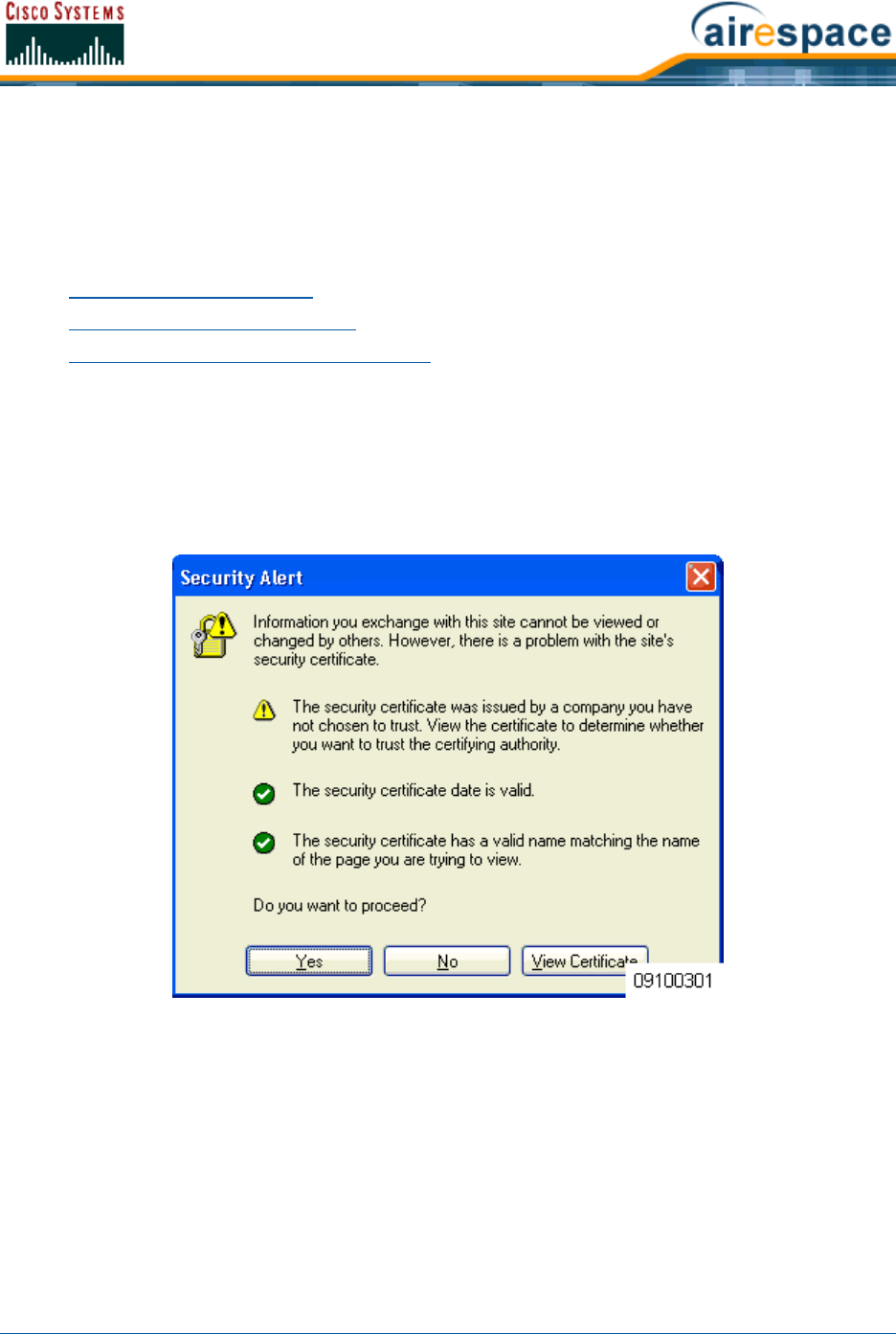
4/1/05 Customizing the Web Auth Login Screen
OL-7426-02
Customizing the Web Auth Login ScreenCustomizing the Web Auth Login Screen
When a Network operator uses Web Authorization (Web Auth) to authenticate clients, the operator
must define Usernames and Passwords for each client, and then the clients must enter a valid
Username and Password when prompted. Because the Cisco SWAN operator may want to customize the
Web Auth Login screen, the following two sections describe the default operation and how to customize
the Web Auth Login screen.
•Default Web Auth Operation
•Customizing Web Auth Operation
•Sample Customized Web Auth Login Page
Default Web Auth OperationDefault Web Auth Operation
When the network operator uses Web Authorization (Web Auth) to authorize clients, the first time
clients attempt to access a URL they may receive a Security Alert from their web browser similar to the
following:
Figure - Typical Security Alert
After answering Yes to the Do you want to Proceed? prompt or if there is no Security Alert,
Operating System redirects the client to a Login screen that the client must use to log in using an
authorized username and password. The following figure shows a typical default Cisco SWAN Login
Screen:
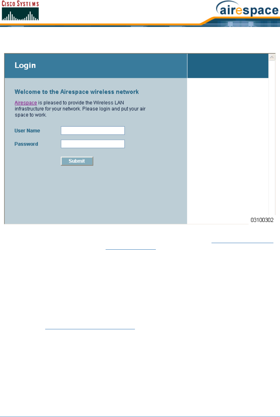
4/1/05 Customizing the Web Auth Login Screen
OL-7426-02
Figure - Default Cisco SWAN Login Screen
The client must respond with a Username and Password predefined using the Local Net Users > New
Web User Interface page, or using the config netuser add Command Line Interface (CLI) command.
Note that the Default Cisco SWAN Login Screen contains Cisco SWAN-specific text and a logo in four
customizable areas:
•The Cisco SWAN logo in the upper-right corner can be deleted and restored.
•The Web Title “Welcome to the Cisco SWAN wireless network”.
•The Web Message “Cisco SWAN is pleased to provide the Wireless LAN infrastructure for your
network. Please login and put your air space to work.”
•A blank area on the right side of the screen for a user-supplied Logo or other graphic.
The Cisco SWAN logo, Web Title, Web Message, and Logo can be customized for each Cisco SWAN as
described in the Customizing Web Auth Operation section.
When the client has entered a valid Username and Password, Operating System typically displays some
version of the following Login Successful page, and then redirects the authenticated client to the origi-
nally requested URL.
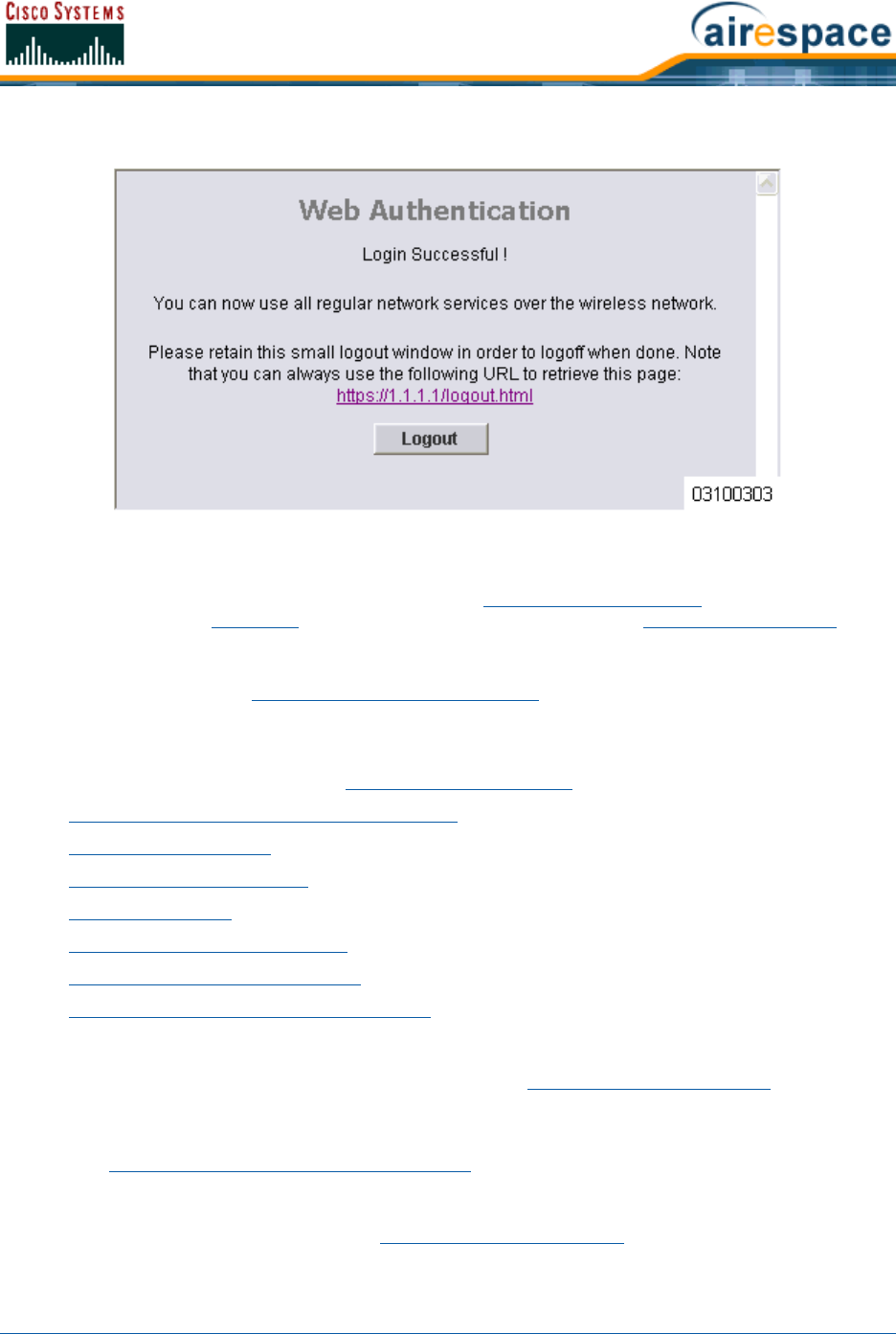
4/1/05 Customizing the Web Auth Login Screen
OL-7426-02
Figure - Default Login Successful Screen
Note that the Default Login Successful Screen contains a pointer to the operator-defined Virtual
Gateway Address URL, redirect https://1.1.1.1/logout.html. This redirect is defined by the Virtual
Gateway IP Address parameter (1.1.1.1) entered while Using the Startup Wizard, as the Virtual
Gateway Address in the Interfaces Web User Interface page, or using the config interface create
Command Line Interface (CLI) command.
Also note that the Cisco SWAN operator may want to redirect the authenticated client to a different
URL. This is described in the Customizing Web Auth Operation section.
Customizing Web Auth OperationCustomizing Web Auth Operation
You can customize Web Auth operation Using the Cisco SWAN CLI commands as follows:
•Clearing and Restoring the Cisco SWAN Logo
•Changing the Web Title
•Changing the Web Message
•Changing the Logo
•Creating a Custom URL Redirect
•Verifying your Web Auth Changes
•Sample Customized Web Auth Login Page
Clearing and Restoring the Cisco SWAN LogoClearing and Restoring the Cisco SWAN Logo
You can delete or restore the Cisco SWAN logo shown in the Default Web Auth Operation section using
the config custom-web weblogo command:
>config custom-web weblogo <disable/enable>
Refer to the Sample Customized Web Auth Login Page for an example.
Changing the Web TitleChanging the Web Title
You can change the Web Title shown in the Default Web Auth Operation section using the config
custom-web webtitle command:
>config custom-web webtitle <string>

4/1/05 Customizing the Web Auth Login Screen
OL-7426-02
To change the Web Title again, enter the config custom-web webtitle command again with a new
<string>. Refer to the Sample Customized Web Auth Login Page for an example.
To change the Web Title back to the Cisco SWAN default “Welcome to the Cisco SWAN wireless
network”, use the clear webtitle command:
>clear webtitle
Changing the Web MessageChanging the Web Message
You can change the Web Message shown in the Default Web Auth Operation section using the config
custom-web webmessage command:
>config custom-web webmessage <string>
To change the Web Message again, enter the config custom-web webtitle command again with a new
<string>. Refer to the Sample Customized Web Auth Login Page for an example.
To change the Web Message back to the Cisco SWAN default “Cisco SWAN is pleased to provide the
Wireless LAN infrastructure for your network. Please login and put your air space to work.”, use the
clear webmessage command:
>clear webmessage
Changing the LogoChanging the Logo
You can add or change a Logo or other graphic in the right side of the Web Auth Login screen as
described in the Default Web Auth Operation section using the following instructions.
•Preparing the TFTP Server
•Copying the Logo or Graphic to the TFTP Server
•Downloading the Logo or Graphic
Preparing the TFTP ServerPreparing the TFTP Server
•Be sure you have a TFTP server available for the Logo or Graphic image download.
-If you are downloading through the Service port, the TFTP server MUST be on the same
subnet as the Service port, because the Service port is not routable.
-If you are downloading through the DS (Distribution System) network port, the TFTP
server can be on the same or a different subnet, because the DS port is routable.
•In the CLI, use the ping <IP Address> command to ensure that the Cisco Wireless LAN
Controller can contact the TFTP server.
Copying the Logo or Graphic to the TFTP ServerCopying the Logo or Graphic to the TFTP Server
•Create a Logo or Graphic image in .JPG, .GIF, or .PNG format with a maximum size of
30 kilobits (recommended size of 180 W x 360 H pixels).
•Be sure the Logo or Graphic image filename contains no spaces.
•Copy the desired Logo or Graphic image file to the default directory on your TFTP server.
Downloading the Logo or GraphicDownloading the Logo or Graphic
•In the CLI, use the transfer download start command, and answer ‘n’ to the prompt to view
the current download settings:
Note: The TFTP server cannot run on the same computer as the Cisco Wireless
Control System, because Cisco WCS and the TFTP server use the same communica-
tion port.

4/1/05 Customizing the Web Auth Login Screen
OL-7426-02
>transfer download start
Mode........................................... TFTP
Data Type...................................... Code
TFTP Server IP................................. xxx.xxx.xxx.xxx
TFTP Path...................................... <directory path>
TFTP Filename..................................... <filename.jpg|.gif|.png>
Are you sure you want to start? (y/n) n
Transfer Canceled
>
•To change the download settings, use the following:
>transfer download mode tftp
>transfer download datatype image
>transfer download serverip <TFTP server IP address>
>transfer download filename <filename.gif|filename.jpg|filename.png>
>transfer download path <absolute TFTP server path to the update file>
•In the CLI, use the transfer download start command to view the updated settings, and
answer ‘y’ to the prompt to confirm the current download settings and start the Operating
System code download:
>transfer download start
Mode........................................... TFTP
Data Type...................................... Login Image
TFTP Server IP................................. xxx.xxx.xxx.xxx
TFTP Path...................................... <directory path>
TFTP Filename.................................. <filename.jpg|.gif|.png>
This may take some time.
Are you sure you want to start? (y/n) y
TFTP Image transfer starting.
Image installed.
To change the Logo or Graphic image again, repeat these commands again using a new filename. Refer
to the Sample Customized Web Auth Login Page for an example.
To remove the Logo or Graphic image from the Web User Interface Login screen, use the clear
webimage command:
>clear webimage
Creating a Custom URL RedirectCreating a Custom URL Redirect
To have Operating System redirect all clients to a specific URL (including http:// or https://) after Web
Authentication, use the config custom-web redirect url command:
>config custom-web redirecturl <URL>
To change the Web Message again, enter the config custom-web redirect-url command again with a
new <URL>.
For example, if you want to redirect all clients to www.AcompanyBC.com, use the following command:
>config custom-web redirecturl www.AcompanyBC.com
Note: Some TFTP servers require only a forward slash “/” as the <TFTP server IP
address>, and the TFTP server automatically determines the path to the correct
directory.

4/1/05 Customizing the Web Auth Login Screen
OL-7426-02
To change the redirect back to the originally requested URL, use the clear redirect-url command:
>clear redirecturl
Verifying your Web Auth ChangesVerifying your Web Auth Changes
Use the show custom-web command to verify your Web Auth operation changes:
Default State
>show custom-web
Cisco Logo................................. Enabled
CustomLogo..................................... Disabled
Custom Title................................... Disabled
Custom Message................................. Disabled
Custom Redirect URL............................ Disabled
External Web Authentication Mode............... Disabled
External Web Authentication URL................ Disabled
Typical Modified State
>show custom-web
Cisco Logo................................. Disabled
CustomLogo..................................... 00_logo.gif
Custom Title................................... Welcome to the AcompanyBC Wireless LAN!
Custom Message................................. Contact the System Administrator for a
Username and Password.
Custom Redirect URL............................ http://www.AcompanyBC.com
External Web Authentication Mode............... Disabled
External Web Authentication URL................ Disabled
Sample Customized Web Auth Login PageSample Customized Web Auth Login Page
Here is a sample of a customized Web Auth Login page, and the commands used to create it:
>config custom-web weblogo disable
>config custom-web webtitle Welcome to the AcompanyBC Wireless LAN!
>config custom-web webmessage Contact the System Administrator for a Username
and Password.
>transfer download start
Mode........................................... TFTP
Data Type...................................... Login Image
TFTP Server IP................................. xxx.xxx.xxx.xxx
TFTP Path...................................... /
TFTP Filename.................................. Logo.gif
This may take some time.
Are you sure you want to start? (y/n) y
TFTP Image transfer starting.
Image installed.
>config custom-web redirecturl http://www.AcompanyBC.com
>show custom-web
Cisco Logo................................. Disabled
CustomLogo..................................... 00_logo.gif
Custom Title................................... Welcome to the AcompanyBC Wireless LAN!
Custom Message................................. Contact the System Administrator for a
4/1/05 Customizing the Web Auth Login Screen
OL-7426-02
Username and Password.
Custom Redirect URL............................ http://www.AcompanyBC.com
External Web Authentication Mode............... Disabled
External Web Authentication URL................ Disabled
When a client attempts to connect to a URL, the following customized Web Auth screen appears:
Figure - Sample Customized Login Screen
After a successful Web Authorization, the client is redirected to the http://www.AcompanyBC.com URL.

4/1/05 Configuring Identity Networking for Operating System 2.2
OL-7426-02
Configuring Identity Networking for Operating System 2.2Configuring Identity Networking for Operating System 2.2
This document explains the Identity Networking feature of Operating System 2.2, how it is configured
and the expected behavior for various security policies.
In previous Operating System releases, each WLAN had a static policy that would be applied to all
mobile clients associated with the SSID. Although very powerful, this method has limitations since it
requires clients to associate with different SSIDs to inherit different QoS and security policies.
The 2.2 version of the Operating System introduces a new feature, Identity Networking, that allows the
network to advertise a single SSID, yet allow for specific users to inherit different QoS or security
policies, based on their user profiles. The specific policies that may be overridden include:
•Quality of Service. When present in a RADIUS Access Accept, the QoS-Level value overrides the
QoS value specified in the WLAN profile.
•ACL. When the ACL attribute is present in the RADIUS Access Accept, the system applies the
ACL-Name to the client station after authentication occurs. This overrides any ACLs that are
assigned to the interface.
•VLAN. When a VLAN Interface-Name or VLAN-Tag is present in a RADIUS Access Accept, the
system places the client on a specific interface.
•Tunnel Attributes.
In order for this feature to be enabled, on a per WLAN basis, the Enable AAA Override configuration flag
must be enabled.
The Operating System’s local MAC Filter database has been extended to include the interface name,
allowing local MAC filters to specify to which interface the client should be assigned. A separate RADIUS
server can also be used, but the RADIUS server must be defined using the Security menus.
The following sections explain the RADIUS attributes.
RADIUS Attributes
QoS-LevelQoS-Level
This attribute indicates the Quality of Service level to be applied to the mobile client's traffic within the
switching fabric, as well as over the air. A summary of the QoS-Level Attribute format is shown below.
The fields are transmitted from left to right.
0 1 2 3
0 1 2 3 4 5 6 7 8 9 0 1 2 3 4 5 6 7 8 9 0 1 2 3 4 5 6 7 8 9 0 1
+-+-+-+-+-+-+-+-+-+-+-+-+-+-+-+-+-+-+-+-+-+-+-+-+-+-+-+-+-+-+-+-+
| Type | Length | Vendor-Id
+-+-+-+-+-+-+-+-+-+-+-+-+-+-+-+-+-+-+-+-+-+-+-+-+-+-+-+-+-+-+-+-+
Vendor-Id (cont.) | Vendor type | Vendor length |
+-+-+-+-+-+-+-+-+-+-+-+-+-+-+-+-+-+-+-+-+-+-+-+-+-+-+-+-+-+-+-+-+
| QoS Level |
+-+-+-+-+-+-+-+-+-+-+-+-+-+-+-+-+-+-+-+-+-+-+-+-+-+-+-+-+-+-+-+-+
Note: This feature is ONLY available with MAC Filtering, 802.1X and WPA. This
feature WILL NOT WORK with Web Auth or IPSec.
Note: When any of the other RADIUS attributes in this section are returned, the
Tunnel Attributes must also be returned.

4/1/05 Configuring Identity Networking for Operating System 2.2
OL-7426-02
•Type - 26 for Vendor-Specific
•Length - 10
•Vendor-Id - 14179
•Vendor type - 2
•Vendor length - 4
•Value - Three octets:
-0 - Silver (Best Effort)
-1 - Gold (Video)
-2 - Platinum (Voice)
-3 - Bronze (Background)
ACL-NameACL-Name
This attribute indicates the ACL name to be applied to the client. A summary of the ACL-Name Attribute
format is shown below. The fields are transmitted from left to right.
0 1 2 3
0 1 2 3 4 5 6 7 8 9 0 1 2 3 4 5 6 7 8 9 0 1 2 3 4 5 6 7 8 9 0 1
+-+-+-+-+-+-+-+-+-+-+-+-+-+-+-+-+-+-+-+-+-+-+-+-+-+-+-+-+-+-+-+-+
| Type | Length | Vendor-Id
+-+-+-+-+-+-+-+-+-+-+-+-+-+-+-+-+-+-+-+-+-+-+-+-+-+-+-+-+-+-+-+-+
Vendor-Id (cont.) | Vendor type | Vendor length |
+-+-+-+-+-+-+-+-+-+-+-+-+-+-+-+-+-+-+-+-+-+-+-+-+-+-+-+-+-+-+-+-+
| ACL Name...
+-+-+-+-+-+-+-+-+-+-+-+-+-+-+-
•Type - 26 for Vendor-Specific
•Length - >7
•Vendor-Id - 14179
•Vendor type - 6
•Vendor length - >0
•Value - A string that includes the name of the ACL to use for the client
Interface-NameInterface-Name
This attribute indicates the VLAN Interface a client is to be associated to.
A summary of the Interface-Name Attribute format is shown below. The fields are transmitted from left
to right.
0 1 2 3
0 1 2 3 4 5 6 7 8 9 0 1 2 3 4 5 6 7 8 9 0 1 2 3 4 5 6 7 8 9 0 1
+-+-+-+-+-+-+-+-+-+-+-+-+-+-+-+-+-+-+-+-+-+-+-+-+-+-+-+-+-+-+-+-+
| Type | Length | Vendor-Id
+-+-+-+-+-+-+-+-+-+-+-+-+-+-+-+-+-+-+-+-+-+-+-+-+-+-+-+-+-+-+-+-+
Vendor-Id (cont.) | Vendor type | Vendor length |

4/1/05 Configuring Identity Networking for Operating System 2.2
OL-7426-02
+-+-+-+-+-+-+-+-+-+-+-+-+-+-+-+-+-+-+-+-+-+-+-+-+-+-+-+-+-+-+-+-+
| Interface Name...
+-+-+-+-+-+-+-+-+-+-+-+-+-+-+-
•Type - 26 for Vendor-Specific
•Length - >7
•Vendor-Id - 14179
•Vendor type - 5
•Vendor length - >0
•Value - A string that includes the name of the interface the client is to be assigned to.
VLAN-TagVLAN-Tag
This attribute indicates the group ID for a particular tunneled session, and is also known as the
Tunnel-Private-Group-ID attribute.
This attribute MAY be included in the Access-Request packet if the tunnel initiator can predetermine the
group resulting from a particular connection and SHOULD be included in the Access-Accept packet if
this tunnel session is to be treated as belonging to a particular private group. Private groups may be
used to associate a tunneled session with a particular group of users. For example, it may be used to
facilitate routing of unregistered IP addresses through a particular interface. It SHOULD be included in
Accounting-Request packets which contain Acct-Status-Type attributes with values of either Start or
Stop and which pertain to a tunneled session.
A summary of the Tunnel-Private-Group-ID Attribute format is shown below. The fields are transmitted
from left to right.
0 1 2 3
0 1 2 3 4 5 6 7 8 9 0 1 2 3 4 5 6 7 8 9 0 1 2 3 4 5 6 7 8 9 0 1
+-+-+-+-+-+-+-+-+-+-+-+-+-+-+-+-+-+-+-+-+-+-+-+-+-+-+-+-+-+-+-+-+
| Type | Length | Tag | String...
+-+-+-+-+-+-+-+-+-+-+-+-+-+-+-+-+-+-+-+-+-+-+-+-+-+-+-+-+-+-+-+-+
•Type - 81 for Tunnel-Private-Group-ID.
•Length - >= 3
•Tag - The Tag field is one octet in length and is intended to provide a means of grouping
attributes in the same packet which refer to the same tunnel. If the value of the Tag field is
greater than 0x00 and less than or equal to 0x1F, it SHOULD be interpreted as indicating which
tunnel (of several alternatives) this attribute pertains. If the Tag field is greater than 0x1F, it
SHOULD be interpreted as the first byte of the following String field.
•String - This field must be present. The group is represented by the String field. There is no
restriction on the format of group IDs.
Tunnel AttributesTunnel Attributes
Note: This Attribute only works when MAC Filtering is enabled, or if 802.1X or WPA is
used as the security policy.
Note: When any of the other RADIUS attributes in this section are returned, the
Tunnel Attributes must also be returned.

4/1/05
OL-7426-02
Reference [RFC2868] defines RADIUS tunnel attributes used for authentication and authorization, and
[RFC2867] defines tunnel attributes used for accounting. Where the IEEE 802.1X Authenticator
supports tunneling, a compulsory tunnel may be set up for the Supplicant as a result of the
authentication.
In particular, it may be desirable to allow a port to be placed into a particular Virtual LAN (VLAN),
defined in [IEEE8021Q], based on the result of the authentication. This can be used, for example, to
allow a wireless host to remain on the same VLAN as it moves within a campus network.
The RADIUS server typically indicates the desired VLAN by including tunnel attributes within the
Access-Accept. However, the IEEE 802.1X Authenticator may also provide a hint as to the VLAN to be
assigned to the Supplicant by including Tunnel attributes within the Access- Request.
For use in VLAN assignment, the following tunnel attributes are used:
•Tunnel-Type=VLAN (13)
•Tunnel-Medium-Type=802
•Tunnel-Private-Group-ID=VLANID
Note that the VLANID is 12-bits, taking a value between 1 and 4094, inclusive. Since the
Tunnel-Private-Group-ID is of type String as defined in [RFC2868], for use with IEEE 802.1X, the
VLANID integer value is encoded as a string.
When Tunnel attributes are sent, it is necessary to fill in the Tag field. As noted in [RFC2868],
section 3.1:
•The Tag field is one octet in length and is intended to provide a means of grouping attributes in
the same packet which refer to the same tunnel. Valid values for this field are 0x01 through
0x1F, inclusive. If the Tag field is unused, it MUST be zero (0x00).
•For use with Tunnel-Client-Endpoint, Tunnel-Server-Endpoint, Tunnel-Private-Group-ID,
Tunnel-Assignment-ID, Tunnel-Client-Auth-ID or Tunnel-Server-Auth-ID attributes (but not
Tunnel-Type, Tunnel-Medium-Type, Tunnel-Password, or Tunnel-Preference), a tag field of
greater than 0x1F is interpreted as the first octet of the following field.
•Unless alternative tunnel types are provided, (e.g. for IEEE 802.1X Authenticators that may
support tunneling but not VLANs), it is only necessary for tunnel attributes to specify a single
tunnel. As a result, where it is only desired to specify the VLANID, the tag field SHOULD be set
to zero (0x00) in all tunnel attributes. Where alternative tunnel types are to be provided, tag
values between 0x01 and 0x1F SHOULD be chosen.

4/1/05 © 2005 All Rights Reserved.
OL-7426-02
TASKSTASKS
You can perform the following tasks using the Cisco Structured Wireless-Aware Network (Cisco SWAN):
Deployment and Quick Start Guides
•The Cisco 1000 Series IEEE 802.11a/b/g Lightweight Access Point Deployment Guide helps you
determine the number of Cisco 1000 Series IEEE 802.11a/b/g lightweight access points a site
needs, where to place the Cisco 1000 Series IEEE 802.11a/b/g lightweight access points, and to
perform a minimal site survey, if necessary.
•The External-Antenna AP1020 and AP1030 Cisco 1000 Series IEEE 802.11a/b/g Lightweight
Access Point Quick Start Guide provides steps for installing Cisco 1000 Series lightweight
access points with internal antennas and connectors for external antennas.
•The Internal-Antenna AP1010 Cisco 1000 Series IEEE 802.11a/b/g Lightweight Access Point
Quick Start Guide provides steps for installing Cisco 1000 Series lightweight access points with
internal antennas and no connectors for external antennas.
•The Cisco 2000 Series Wireless LAN Controller Quick Start Guide guides you through installing
Cisco 2000 Series Wireless LAN Controllers.
•The Cisco 4100 Series Wireless LAN Controller Quick Start Guide guides you through installing
Cisco 4100 Series Wireless LAN Controllers.
•The Windows Cisco WCS Quick Start Guide and Linux Cisco WCS Quick Start Guide give details
on how to install Cisco Wireless Control System (Cisco WCS).
OS Command Line Interface (CLI)
•Using the Cisco SWAN CLI describes how to access and use the Cisco SWAN Command Line
Interface.
•Configuring the Cisco Wireless LAN Controllers details how to use the CLI to configure a Cisco
Wireless LAN Controller.
Cisco SWAN Switch Web Interface
•Using the Web User Interface helps operators access and use the Web User Interface.
Cisco Wireless Control System (Cisco WCS)
•Using the Cisco Wireless Control System describes how to access and use the Cisco Wireless
Control System.
•Updating the Operating System Software provides operators with instructions on how to update
the Cisco Wireless LAN Controller (and associated Cisco 1000 Series lightweight access point)
OS software.
•Updating Windows Cisco WCS describes how to update Cisco WCS images on Cisco WCS
workstations.
•Updating Linux Cisco WCS describes how to update Cisco WCS images on Cisco WCS
workstations.
•Reinitializing the Windows Cisco WCS Database describes how to reinitialize the Cisco WCS
database on Windows Cisco WCS workstations.

4/1/05 TASKS
OL-7426-02
•Reinitializing the Linux Cisco WCS Database describes how to reinitialize the Cisco WCS
database on Linux Cisco WCS workstations.
•Transferring Files To and From a Cisco Wireless LAN Controller describes uploading and
downloading files from a Cisco Wireless LAN Controller.
•Viewing Network Status helps you monitor the Cisco SWAN network status.
Troubleshooting
•Troubleshooting Tips contains information you can use to troubleshoot the Cisco SWAN.

4/1/05 Using the Cisco SWAN CLI
OL-7426-02
Using the Cisco SWAN CLIUsing the Cisco SWAN CLI
The Command Line Interface allows operators to configure any Cisco Wireless LAN Controller and its
associated Cisco 1000 Series lightweight access points using the Command Line Interface. Refer to the
following sections or refer to the Cisco SWAN CLI Reference for more information:
•Logging Into the CLI
-Using a Local Serial Connection
-Using a Remote Ethernet Connection
•Logging Out of the CLI
•Navigating the CLI
•Using the Startup Wizard
•Saving Configurations
•Erasing the Cisco Wireless LAN Controller Configuration
•Resetting the Cisco Wireless LAN Controller
Logging Into the CLILogging Into the CLI
You may access the Cisco Wireless LAN Controller CLI using either of two methods:
•A direct ASCII serial connection to the Cisco Wireless LAN Controller Console Port.
•A remote console session over Ethernet through the pre-configured Service Port or Distribution
System Ports (configured using the Cisco 2000 Series Wireless LAN Controller Quick Start
Guide or Cisco 4100 Series Wireless LAN Controller Quick Start Guide).
The following sections contain information on how to use the Command Line Interface. This document
assumes the Cisco Wireless LAN Controller has been initialized as described in the Cisco 2000 Series
Wireless LAN Controller Quick Start Guide or Cisco 4100 Series Wireless LAN Controller Quick Start
Guide.
Before you log into the Command Line Interface, you must configure your connectivity and environ-
ment variables based on the type of connection you are using. Refer to the appropriate section for your
connection:
•Using a Local Serial Connection
•Using a Remote Ethernet Connection
Using a Local Serial ConnectionUsing a Local Serial Connection
You will need:
•A computer running a terminal emulation program and a DB-9 serial port.
•A DB-9 male to female null-modem serial cable.
Use this procedure to configure a serial connection to your Cisco Wireless LAN Controller:
1. Connect your computer to the Cisco Wireless LAN Controller using the DB-9 null-modem serial
cable as shown in the following figure.
Note: You can use the local serial connection at any time, whether or not the Cisco
Wireless LAN Controller has been configured as described in the Cisco 2000 Series
Wireless LAN Controller Quick Start Guide or Cisco 4100 Series Wireless LAN
Controller Quick Start Guide.

4/1/05 Logging Into the CLI
OL-7426-02
2. Verify that your terminal emulation (HyperTerminal, ProComm, minicom, tip, or other) inter-
face is configured with the following parameters:
-9600 baud
-8 data bits
-1 stop bit
-no parity
-no hardware flow control
3. In your terminal emulation program, open a session with the Cisco Wireless LAN Controller.
4. Press <RETURN>. The CLI returns a login prompt.
5. Enter a valid login and password to enter the CLI. (The default login and password are admin
and admin, respectively.)
User:
Password:
Note that the login and password functions are case sensitive.
6. The CLI displays the root-level system prompt:
(system prompt)>
The CLI allows a default of five users to be logged in at a time, but this number can be set from
zero to five users.
The system prompt can be any alphanumeric string up to 31 characters. Because this is a
user-defined variable, it is omitted from the rest of this documentation.
The CLI automatically logs you out without saving any changes after a short period of inactivity.
This automatic logout can be set from 0 (never log out), or from 1 to 160 minutes. (Use the CLI
command config serial timeout x, where x is a number between 0 and 160.)
You are now logged into the CLI.
Using a Remote Ethernet ConnectionUsing a Remote Ethernet Connection
You will need:
•A computer with access to the Cisco Wireless LAN Controller over the Ethernet network
•The IP Address of the Cisco Wireless LAN Controller
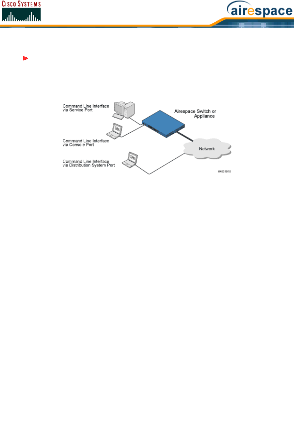
4/1/05 Logging Out of the CLI
OL-7426-02
•You may use either a terminal emulation program or a DOS shell for the Telnet session.
Your computer may connect to the Cisco Wireless LAN Controller through the network using one of a
variety of paths as shown in the following illustration.
1. Verify that your terminal emulation or DOS shell interface is configured with the following
parameters:
-Ethernet address
-Port 23
2. In your terminal emulation interface, use the Cisco Wireless LAN Controller IP Address to Telnet
to the Cisco Wireless LAN Controller Command Line Interface. The CLI returns a login prompt.
3. Enter a valid login and password to enter the CLI. (The default login and password are admin
and admin, respectively.)
User:
Password:
Note that the login and password functions are case sensitive. The CLI allows a default of five
users to be logged in at a time, but this number can be set from zero to five users.
4. The CLI displays the root-level system prompt:
(system prompt)>
The CLI allows a default of five users to be logged in at a time, but this number can be set from
zero to five users.
The system prompt can be any alphanumeric string up to 31 characters, and can be changed.
Because this is a user-defined variable, it is omitted from the rest of this documentation.
The CLI automatically logs you out without saving any changes after a short period of inactivity.
This automatic logout can be set from 0 (never log out), or from 1 to 160 minutes. (Use the CLI
command config serial timeout x, where x is a number between 0 and 160.)
You are now logged into the CLI.
Logging Out of the CLILogging Out of the CLI
•When you are done using the Command Line Interface, navigate to the root level and enter
logout. You will be prompted to save any changes you have made to the volatile RAM.
Note: By default, Telnet sessions are not allowed. You will need to enable Telnet
sessions using your serial connection, and using the Cisco SWAN CLI or Web User
Interface.

4/1/05 CLI Tree Structure
OL-7426-02
CLI Tree StructureCLI Tree Structure
The Command Line Interface tree structure is organized around five levels:
Root Level
Level 2
Level 3
Level 4
Level 5
Following are some examples of CLI commands and their position in the tree structure.
?
help
clear
config
show
802.11a
config
advanced
802.11a
profile
noise
level
save
config
transfer
download
start
To view the latest CLI tree structure, log onto the CLI and use the Navigating the CLI commands.
Navigating the CLINavigating the CLI
•You start at the root level.
•At the root level, type ‘help’ to see systemwide navigation commands.
•At all levels, type ‘?’ to view the commands available from the current location.
•At all levels, type a command followed by ‘?’ or ‘ ?’ to view the parameters available for the
command.
•Type any command name to move up to that level.
Note: If you have recently cleared the volatile RAM configurations using Clearing
Configurations and you save the configuration from the volatile RAM to the NVRAM,
you will have to reconfigure the Cisco Wireless LAN Controller after reboot using the
Startup Wizard.

4/1/05 Viewing Network Status
OL-7426-02
•Type ‘exit’ to go down a level.
•Enter <CTRL-Z> to return to the root level.
•From the root level, you can enter the whole command name. For instance, you can enter:
>config prompt “Ent1”
to change the system prompt to Ent1 >.
•To save your changes from active working RAM to non-volatile RAM (NVRAM) so they are
retained upon reboot, use the save config command at the CLI root level.
•To reset the Cisco Wireless LAN Controller without logging out, use the reset system
command at the root level of the CLI tree structure.
•When you are done using the CLI console, navigate to the root level and enter logout. You will
be prompted to save any changes you have made from the active working RAM to the
non-volatile RAM (NVRAM).
Viewing Network StatusViewing Network Status
Use the following Command Line Interface commands to view the status of the network controlled by
an Cisco Wireless LAN Controllers.
•Use the show client commands to display client information for each Cisco 1000 Series light-
weight access point 802.11a and 802.11b/g RF coverage area, to display detailed information
for a client connected through a particular Cisco 1000 Series lightweight access point, and
display a summary of clients connected through the Cisco SWAN:
>show client ap [802.11a/802.11b] <Cisco 1000 Series lightweight access
point>
>show client detail <MAC addr>
>show client summary
If you need to, use the config client deauthenticate command to deauthenticate an indi-
vidual <MAC address>.
•Use the show rogue-ap summary and show rogue-ap detail commands to discover
Rogue APs on the subnet. If necessary, use the config rogue-ap acknowledged, config
rogue-ap alert, and config rogue-ap known commands to mark the Rogue APs in the Cisco
SWAN database.
•In general, use the show commands to view the Cisco SWAN status.
•To test a link to a MAC address, use the linktest command at the CLI root level. Note that
linktest does not work for IPSec links and does not work from Cisco 1000 Series IEEE
802.11a/b/g lightweight access points.
•To ping an IP Address, use the ping command at the CLI root level.
Continue with Using the Cisco SWAN CLI.

4/1/05 Configuring the Cisco Wireless LAN Controllers
OL-7426-02
Configuring Cisco Wireless LAN ControllersConfiguring the Cisco Wireless LAN Controllers
This section assumes that the Cisco Wireless LAN Controller is already installed, initially configured, and
connected as described in the Cisco 2000 Series Wireless LAN Controller Quick Start Guide or Cisco
4100 Series Wireless LAN Controller Quick Start Guide.
Continue with the following sections to configure a Cisco Wireless LAN Controller using the Command
Line Interface (CLI):
•Logging Into the CLI
•Navigating the CLI
•Collecting Cisco Wireless LAN Controller Parameters
•Configuring System Parameters
•Configuring Cisco Wireless LAN Controller Interfaces
•Configuring WLANs
•Configuring Controller Mobility Groups
•Configuring RADIUS
•Configuring SNMP
•Configuring Other Ports and Parameters
•Transferring Files To and From a Cisco Wireless LAN Controller
•Updating the Operating System Software
•Using the Startup Wizard
•Adding SSL to the Web User Interface
•Adding SSL to the 802.11 Interface
•Saving Configurations
•Clearing Configurations
•Resetting the Cisco Wireless LAN Controller
•Erasing the Cisco Wireless LAN Controller Configuration
•Logging Out of the CLI
Continue with Using the Cisco SWAN CLI.
Collecting Cisco Wireless LAN Controller ParametersCollecting Cisco Wireless LAN Controller Parameters
Collect the high-level Cisco Wireless LAN Controller parameters:
System Parameters
-Supported protocols: 802.11a and/or 802.11b/g.
-New usernames and passwords (optional).
Network (Distribution System) Parameters
-Distribution System (network) port static IP Address, netmask, and optional default
gateway IP Address from the network planner.
-Service port static IP Address and netmask from the network planner (optional).

4/1/05 Configuring System Parameters
OL-7426-02
-Distribution System physical port (1000BASE-T, 1000BASE-SX, or 10/100BASE-T).
Note that each 1000BASE-SX interface provides a 100/1000 Mbps wired connection to
a network through an 850nM (SX) fiber-optic link using an LC physical connector.
-Distribution System port VLAN assignment (optional).
-Distribution System port Web and Secure Web mode settings, enabled or disabled.
-Distribution System port Spanning Tree Protocol: enabled/disabled, 802.1D/fast/off
mode per port, path cost per port, priority per port, bridge priority, forward delay, hello
time, maximum age.
WLAN Parameters
-WLAN Configuration: VLAN assignments, Layer 2 Security settings, Layer 3 Security
settings, QoS assignments.
Mobility Parameters
-Mobility Settings: Controller Mobility Group Name (optional).
RADIUS Parameters
-RADIUS Settings.
SNMP Parameters
-SNMP Settings.
Other Parameters
-Other Port and Parameter Settings: Service port, Cisco SWAN Radio Resource
Management (RRM), Serial/CLI Console port, 802.3x Flow Control, and System
Logging.
Other Actions
-Assemble all files that may need uploading or downloading to the Cisco Wireless LAN
Controller, including the latest OS code.
Continue with Configuring System Parameters.
Configuring System ParametersConfiguring System Parameters
The Cisco Wireless LAN Controller requires a few basic system parameters to communicate with other
network devices. Perform the following to set these parameters:
Time and DateTime and Date
•Use the show time command to view the Cisco Wireless LAN Controller time and date.
•If necessary, set the Cisco Wireless LAN Controller time and date by entering:
>config time MM/DD/YY HH:MM:SS
•Use the show time command to verify that the Cisco Wireless LAN Controller has stored your
input. Continue with the next parameter.
CountryCountry
The Cisco Wireless LAN Controller has been designed to be used in countries with different 802.11
country codes.
•Use the show country command to view the Cisco Wireless LAN Controller countries.

4/1/05 Configuring System Parameters
OL-7426-02
•If necessary, set the Cisco Wireless LAN Controller country code by entering:
>config country <country code>
Where <country code> =
-US (United States of America), which allows 802.11b and 802.11g operation and
802.11a Low, Medium, and High bands.
-USL (US Low), which allows 802.11b and 802.11g operation and 802.11a Low and
Medium bands. (Used for legacy 802.11a interface cards that do not support 802.11a
High band.)
-AU (Australia), which allows 802.11a and 802.11b/g.
-AT (Austria), which allows 802.11a and 802.11b/g.
-BE (Belgium), which allows 802.11a and 802.11b/g.
-CA (Canada), which allows 802.11b/g.
-DK (Denmark), which allows 802.11a and 802.11b/g.
-FI (Finland), which allows 802.11a and 802.11b/g.
-FR (France), which allows 802.11a and 802.11b/g.
-DE (Germany), which allows 802.11a and 802.11b/g.
-GR (Greece), which allows 802.11b/g.
-IE (Ireland), which allows 802.11a and 802.11b/g.
-IN (India), which allows 802.11a and 802.11b.
-IT (Italy), which allows 802.11a and 802.11b/g.
-JP (Japan), which allows 802.11a and 802.11b/g.
-KR (Republic of Korea), which allows 802.11a and 802.11b/g.
-LU (Luxembourg), which allows 802.11a and 802.11b/g.
-NL (Netherlands), which allows 802.11a and 802.11b/g.
-PT (Portugal), which allows 802.11a and 802.11b/g.
-ES (Spain), which allows 802.11a and 802.11b/g.
-SE (Sweden), which allows 802.11a and 802.11b/g.
-GB (United Kingdom), which allows 802.11a and 802.11b/g.
•Continue with the next parameter.
Supported 802.11a and 802.11b/g ProtocolsSupported 802.11a and 802.11b/g Protocols
The 802.11a and 802.11b/g protocols can be independently enabled or disabled.
•Use the show sysinfo command to view the 802.11a and 802.11b/g enabled/disabled status.
Note: Refer to the Cisco SWAN Supported Country Codes section for the most recent
Country Codes.
Note: The Cisco Wireless LAN Controller Country Code only operates with Cisco 1000
Series lightweight access points designed for operation in the associated Regulatory
Domain. Refer to the Cisco SWAN Supported Country Codes for Cisco Wireless LAN
Controller Country Code mapping to Cisco 1000 Series lightweight access point
Regulatory Domains.

4/1/05 Configuring Cisco Wireless LAN Controller Interfaces
OL-7426-02
•Be sure these protocols are configured to agree with your wireless network plan and to comply
with the Country Code entered in the previous step using the following commands:
>config 802.11a enable network
>config 802.11a disable network
>config 802.11b enable network
>config 802.11b disable network
•Use the show sysinfo command to verify that the Cisco Wireless LAN Controller has stored
your input. Continue with the next parameter.
Users and PasswordsUsers and Passwords
After you have configured other system parameters, you are urged to change the username and
password so unauthorized personnel cannot easily log into the Cisco SWAN.
•Use the show mgmtuser command to view the current management usernames.
•Use the following commands to add new usernames and add or change passwords:
>config mgmtuser add <username> <password> [read-write/read-only]
>config mgmtuser password <username> <new password>
where <username>, <password> and <new password> = Any ASCII character string, up to 24
characters, case sensitive, with no spaces.
•Use the show mgmtuser command to verify that your users have been accepted by the system.
Continue with Configuring Cisco Wireless LAN Controller Interfaces.
Configuring Cisco Wireless LAN Controller InterfacesConfiguring Cisco Wireless LAN Controller Interfaces
As described in the Distribution System Ports section, the Cisco 2000 Series Wireless LAN Controller
has four independent physical ports, and the Cisco 4100 Series Wireless LAN Controller has two
redundant physical ports. This means that the Cisco 2000 Series Wireless LAN Controller can connect to
up to four separate subnets, and that the Cisco 4100 Series Wireless LAN Controller can physically
connect to one subnet.
Each of the physical ports can have multiple Interfaces applied to it:
•The Management Interface controls communications with network equipment for all physical
ports in all cases.
When the Cisco SWAN is operated in Layer 2 Mode (see Layer 2 and Layer 3 LWAPP Operation),
the Management Interface also controls communications between the Cisco Wireless LAN
Controller and Cisco 1000 Series IEEE 802.11a/b/g Lightweight Access Points.
When the Cisco SWAN is operated in Layer 3 Mode, the Management Interface no longer
controls communications between the Cisco Wireless LAN Controllers and Cisco 1000 Series
lightweight access points.
•When the Cisco SWAN is operated in Layer 3 Mode (see Layer 2 and Layer 3 LWAPP Operation),
the AP-Manager Interface controls all communications between the Cisco Wireless LAN
Controller and Cisco 1000 Series IEEE 802.11a/b/g Lightweight Access Points.
•Each physical port can also have between one and 512 Operator-Defined Interfaces, also
known as VLAN Interfaces, assigned to it. Each Operator-Defined Interface is individually
configured, and allows separate communication streams to exist on any or all of the physical
port(s).
•The Virtual Interface controls Layer 3 Security and Mobility manager communications for Cisco
Wireless LAN Controllers for all physical Ports. It also maintains the DNS Gateway hostname
used by Layer 3 Security and Mobility managers to verify the source of certificates when
Layer 3 Web Authorization is enabled.

4/1/05 Configuring Cisco Wireless LAN Controller Interfaces
OL-7426-02
•Note that the Cisco 4100 Series Wireless LAN Controller also has a Service-Port Interface, but
that Interface can only be applied to the front-panel Service Port.
If you have not already done so, you must decide which physical port(s) you want to use, and then
create and assign the following:
•Verifying and Changing the Management Interface
•Creating and Assigning the AP-Manager Interface
•Creating, Assigning and Deleting Operator-Defined Interfaces
•Verifying and Changing the Virtual Interface
Continue with the next section to configure the Distribution System IP Address.
Verifying and Changing the Management InterfaceVerifying and Changing the Management Interface
Normally, the static Management Interface parameters are defined when the Cisco Wireless LAN
Controller is initially configured using the Startup Wizard. However, you may want to verify and/or
change its parameters:
•Use the show interface detailed management command to view the current Management
Interface settings. Note that the Management Interface uses the burned-in MAC address.
•To change any of the parameters, disable all WLANs.
>show wlan summary
>config wlan disable <1-16, or 17 for Third-Party APs> (repeat for all enabled
WLANs)
•And then use the following:
>config interface address management <IP addr> <IP netmask> [optional
gateway]
>config interface vlan management <VLAN ID|’0’ for untagged>
>config interface port management <Physical DS Port Number>
>config interface dhcp management <IP addr of Primary DHCP server> <IP addr
of optional Secondary DHCP server>
>config interface acl management <Access Control List Name> (Note)
using the values collected from the network planner in Collecting Cisco Wireless LAN Controller
Parameters.
Use the show interface detailed management command to verify that the Cisco Wireless LAN
Controller has correctly stored your inputs. Note that this Interface cannot be deleted. Continue with
the next section.
Creating and Assigning the AP-Manager InterfaceCreating and Assigning the AP-Manager Interface
The static AP-Manager Interface only exists when the Cisco SWAN is operating in LWAPP Layer 3 Mode
(see Layer 2 and Layer 3 LWAPP Operation).
•Use the show interface summary command to view the current Interfaces.
If the Cisco SWAN is operating in Layer 2 Mode, the ap-manager interface will not be listed.
Either skip this section and continue with Creating, Assigning and Deleting Operator-Defined
Interfaces, or go to Converting a Cisco SWAN from Layer 2 to Layer 3 Mode.
Note: If you are applying an Access Control List (ACL) to the Management Interface,
you must first configure the ACL using the Creating Access Control Lists section.

4/1/05 Configuring Cisco Wireless LAN Controller Interfaces
OL-7426-02
•Use the show interface detailed ap-manager command to view the current AP-Manager
Interface settings.
•To change any of the parameters, disable all WLANs.
>show wlan summary
>config wlan disable <1-16, or 17 for Third-Party APs> (repeat for all enabled
WLANs)
•And then use the following:
>config interface address ap-manager <IP addr> <IP netmask> [optional
gateway]
>config interface vlan ap-manager <VLAN ID|’0’ for untagged>
>config interface port ap-manager <Physical DS Port Number>
>config interface dhcp ap-manager <IP addr of Primary DHCP server> <IP addr
of optional Secondary DHCP server>
>config interface acl ap-manager <Access Control List Name> (Note)
using the values collected from the network planner in Collecting Cisco Wireless LAN Controller
Parameters.
Use the show interface detailed ap-manager command to verify that the Cisco Wireless LAN
Controller has correctly stored your inputs. Note that this Interface cannot be deleted. Continue with
the next section.
Creating, Assigning and Deleting Operator-Defined InterfacesCreating, Assigning and Deleting Operator-Defined Interfaces
Each Cisco Wireless LAN Controller can support up to 512 dynamic Operator-Defined Interfaces. Each
Operator-Defined Interface controls VLAN and other communications between Cisco Wireless LAN
Controllers and all other network devices. Between one and 512 Operator-Defined Interfaces can be
assigned to Cisco SWAN WLANs, physical Distribution System Ports, the Layer 2 Management Inter-
face, and the Layer 3 AP-Manager Interface.
•Use the show interface summary command to view the current Operator-Defined Interfaces.
They can be identified by the ‘dynamic’ Interface type.
•To view the details of an Operator-Defined Interface, use the show interface detailed
<operator-defined interface name> command to view the current Operator-Defined
Interface settings.
•To change any of the parameters or add another Operator-Defined Interface, disable all
WLANs.
>show wlan summary
>config wlan disable <1-16, or 17 for Third-Party APs> (repeat for all enabled
WLANs)
Note: If you are applying an Access Control List (ACL) to the Management Interface,
you must first configure the ACL using the Creating Access Control Lists section.
Note: Operator-Defined Interfaces cannot be assigned to the dedicated Cisco 4100
Series Wireless LAN Controller front-panel Service Port.
CAUTION: Operator-Defined Interface names cannot have spaces in them. If an
Operator-Defined Interface name contains a space, you may not be able to edit its
configuration using the Command Line Interface.

4/1/05 Configuring Cisco Wireless LAN Controller Interfaces
OL-7426-02
•And then use the following:
>config interface create <operator-defined interface name> <VLAN ID|’0’ for
untagged>
>config interface address <operator-defined interface name> <IP addr> <IP
netmask> [optional gateway]
>config interface vlan <operator-defined interface name> <VLAN ID|’0’ for
untagged>
>config interface port <operator-defined interface name> <Physical DS Port
Number>
>config interface dhcp <operator-defined interface name> <IP addr of Primary
DHCP server> <IP addr of optional Secondary DHCP server>
>config interface acl <operator-defined interface name> <Access Control List
Name> (Note)
using the values collected from the network planner in Collecting Cisco Wireless LAN Controller
Parameters.
Use the show interface detailed <operator-defined interface name> and show interface
summary commands to verify that the Cisco Wireless LAN Controller has correctly stored your inputs.
•To delete an Operator-Defined Interface, use the following command:
>config interface delete <operator-defined interface name>
Continue with the next section.
Verifying and Changing the Virtual InterfaceVerifying and Changing the Virtual Interface
The static Virtual Interface controls Layer 3 Security and Mobility manager communications for Cisco
Wireless LAN Controllers, and it maintains the DNS Gateway hostname used by Layer 3 Security and
Mobility managers to verify the source of certificates when Layer 3 Web Authorization is enabled.
•Use the show interface detailed virtual command to view the current AP-Manager
Interface settings.
•To change any of the parameters, disable all WLANs.
>show wlan summary
>config wlan disable <1-16, or 17 for Third-Party APs> (repeat for all enabled
WLANs)
•And then use the following:
>config interface address virtual <IP addr> where <IP addr> is any fictitious,
unassigned, unused Gateway IP Address.
>config interface hostname virtual <DNS Host Name>
using the values collected from the network planner in Collecting Cisco Wireless LAN Controller
Parameters.
Note: If you are applying an Access Control List (ACL) to the Operator-Defined Inter-
face, you must first configure the ACL using the Creating Access Control Lists
section.
Note: If you change any of the Virtual Interface settings, reset the Cisco Wireless
LAN Controller and save the configuration as described in Resetting the Cisco
Wireless LAN Controller.

4/1/05 Configuring Cisco Wireless LAN Controller Interfaces
OL-7426-02
Use the show interface detailed virtual command to verify that the Cisco Wireless LAN Controller
has correctly stored your inputs. Note that this Interface cannot be deleted. Continue with the next
section.
Enabling Web and Secure Web ModesEnabling Web and Secure Web Modes
•Use the following commands to enable (default) or disable the Distribution System port as a
Web port and/or a Secure Web port:
>config network webmode [enable/disable]
>config network secureweb [enable/disable]
Use the show network command to verify that your inputs were accepted. Continue with the next
parameter.
Configuring Spanning Tree ProtocolConfiguring Spanning Tree Protocol
Spanning Tree Protocol is initially disabled for the Distribution System (network) ports. You can enable
STP on the Cisco Wireless LAN Controller for all physical ports using the following commands. If you are
not configuring Spanning Tree Protocol at this time, skip this section.
•Use the show spanningtree port and show spanningtree switch commands to view the
current STP status.
•Disable STP on the Cisco Wireless LAN Controller by entering:
>config spanningtree switch mode disable
This causes the Cisco Wireless LAN Controller to disable support for STP on all ports.
•Configure the STP port administrative mode on the desired ports using one of the following
commands:
>config spanningtree port mode 802.1d [<port number>/all] (default)
>config spanningtree port mode fast [<port number>/all]
>config spanningtree port mode off <[<port number>/all]
where <port number> = 1 through 13 or 1 through 25, and all = all ports.
•Configure STP port path cost on the STP ports using one of the following commands:
>config spanningtree port pathcost <1-65535> [<port number>/all]
>config spanningtree port mode pathcost auto [<port number>/all] (default)
where <1-65535> = Path cost supplied by the network planner, and auto = allow the STP algo-
rithm to automatically assign the path cost (default).
•Configure port priority on the STP ports using the following command:
>config spanningtree port priority <0-255> <port number>
where <0-255> = STP priority for this port (default priority = 128).
•If required, configure the Cisco Wireless LAN Controller STP bridge priority using the following
command:
>config spanningtree switch bridgepriority <0-65535>
where <0-65535> = STP bridge priority for this Cisco Wireless LAN Controller (default priority
= 32768).
•If required, configure the Cisco Wireless LAN Controller STP forward delay using the following
command:
Note: STP must be disabled before the STP parameters can be changed; leave STP
disabled until you have finished configuring all associated parameters.

4/1/05 Creating Access Control Lists
OL-7426-02
>config spanningtree switch forwarddelay <4-30>
where <4-30> seconds = STP forward delay for this Cisco Wireless LAN Controller (default
forward delay = 15 seconds).
•If required, configure the Cisco Wireless LAN Controller STP hello time using the following
command:
>config spanningtree switch hellotime <1-10>
where <1-10> seconds = STP hello time for this Cisco Wireless LAN Controller (default hello
time = 2 seconds).
•If required, configure the Cisco Wireless LAN Controller STP maximum age using the following
command:
>config spanningtree switch maxage <6-40>
where <6-40> seconds = STP maximum age for this Cisco Wireless LAN Controller (default =
20 seconds).
•After all the ports have been configured for the desired STP settings, enter the following:
>config spanningtree switch mode enable
This procedure allows the Cisco Wireless LAN Controller to most efficiently set up STP, detect
logical network loops, place redundant ports on standby, and build a network with the most
efficient pathways.
You have configured STP for the Cisco Wireless LAN Controller. Verify that your settings are stored in
memory using the show spanningtree port and show spanningtree switch commands. Continue
with Configuring WLANs.
Creating Access Control ListsCreating Access Control Lists
When you wish to create Access Control Lists, Cisco SWAN strongly recommends that you use the Cisco
Wireless LAN Controller. Refer to the Access Control Lists page in the Web User Interface Online Help
document.
Configuring WLANsConfiguring WLANs
Cisco Wireless LAN Controllers can control up to 16 Cisco SWAN Wireless LANs as described in Cisco
SWAN WLANs.
If you are not configuring WLANs at this time, skip this section and continue with Configuring Controller
Mobility Groups.
WLANsWLANs
•Use the show wlan summary command to display the current WLANs and whether they are
enabled or disabled. Note that each Cisco SWAN WLAN is assigned a WLAN ID from 1 to 16.
•If you are creating WLANs, use the following commands:
>config wlan create <wlan id> <wlan name>
>config wlan create 17 <3rd party wlan name>
where <wlan id> = 1 through 16, <wlan name> = SSID (up to 31 alphanumeric characters).
Note: When WLAN 1 is created in the Startup Wizard, it is created in enabled mode;
disable it until you have finished configuring it. When you create a new WLAN using
the config wlan create command, it is created in disabled mode; leave it disabled
until you have finished configuring it.

4/1/05 Local MAC Filter
OL-7426-02
•If you are modifying enabled WLANs, be sure they are disabled using the show wlan summary
command. If they are not disabled, use the following to disable them:
>config wlan disable <wlan id>
where <wlan id> = 1 through 16. Leave the WLANs in disabled mode until you have finished
configuring them.
•If you are deleting WLANs, use the following command:
>config wlan delete <wlan id>
where <wlan id> = 1 through 16.
DHCP ServerDHCP Server
Each WLAN can be assigned to a DHCP server. Any or all WLANs can be assigned to the same DHCP
server, and each WLAN can be assigned to a different DHCP servers. This assignment is mandatory for
WLANs that allow Management over Wireless, as described in External DHCP Servers.
•Use the show wlan command to verify whether you have a DHCP Server assigned to the WLAN.
•If necessary, use the following command:
>config wlan dhcp_server <WLAN id> <IP Address>
where <WLAN id> = 1 through 16, <IP Address> = DHCP Server IP Address.
•Use the show wlan command to verify that you have a DHCP Server assigned to the WLAN.
MAC FilteringMAC Filtering
Whenever you are going to use MAC filtering for Cisco Wireless LAN Controller or RADIUS authorization,
you need to enable it at the WLAN level first. If you plan to use local MAC address filtering for any
WLAN, use the following commands to configure the MAC Address Filter List:
•Use the show wlan command to verify whether you have MAC filtering enabled or disabled for
each WLAN.
•If necessary, use the following command:
>config wlan mac-filtering enable <WLAN id>
where <WLAN id> = 1 through 16.
•Use the show wlan command to verify that you have MAC filtering enabled or disabled for each
WLAN.
Local MAC FilterLocal MAC Filter
Cisco Wireless LAN Controllers have built-in MAC filtering capability, similar to that provided by a
RADIUS authorization server.
•Use the show macfilter command to verify that you have MAC addresses assigned to WLANs.
•If required, use the following commands to assign local MAC addresses to WLANs, and to
configure a WLAN to filter a local client:
>config macfilter add <MAC addr> <WLAN id>
>config macfilter wlan-id <MAC addr> <WLAN id>
where <MAC addr> = client MAC address and <WLAN id> = 1 through 16.
•Use the show macfilter command to verify that you have MAC addresses assigned to WLANs.

4/1/05 Local MAC Filter
OL-7426-02
Disable TimeoutDisable Timeout
Each WLAN can have a variable timeout for excluded, or disabled clients. Clients who fail to authenti-
cate three times when attempting to associate are automatically excluded, or disabled, from further
association attempts. After the exclusion timeout period expires, the client is allowed to retry authenti-
cation until it associates or fails authentication and is excluded again.
•Use the show wlan command to check the current WLAN Disable (Excluded) Timeout.
•If necessary, use the following command to change the Disable (Excluded) Timeout:
>config wlan blacklist <WLAN id> <timeout>
where <WLAN id> = 1 through 16, and <timeout> = 1 to 65535 seconds, 0 to add to the
Exclusion List (formerly blacklist) permanently until the operator manually removes the
exclusion.
•Use the show wlan command to verify the current WLAN Disable (Excluded) Timeout.
VLANsVLANs
•Use the show wlan command to verify VLAN assignment status.
•To assign a VLAN to a WLAN, use the following command:
>config wlan vlan <wlan id> [<default>/<untagged>/<VLAN ID> <IP Address>
<VLAN Netmask> <VLAN Gateway>]
where <WLAN id> = 1 through 16, <default> = use the VLAN configured on the network port,
<untagged> = use VLAN 0, <VLAN id> = 1 through 4095, <IP Address> = the VLAN IP
Address on the Cisco Wireless LAN Controller, <VLAN Netmask> = VLAN local IP netmask, and
<VLAN Gateway> = VLAN local IP gateway.
•To remove a VLAN assignment from a WLAN, use the following command:
>config wlan vlan <WLAN id> untagged
where <WLAN id> = 1 through 16.
•Use the show wlan <wlan id> command to verify that you have correctly assigned a VLAN to
the WLAN.
Layer 2 SecurityLayer 2 Security
Dynamic 802.1X Keys and AuthorizationDynamic 802.1X Keys and Authorization
Cisco Wireless LAN Controllers can control 802.1X dynamic keys using EAP (extensible authentication
protocol) across Cisco 1000 Series lightweight access points, and supports 802.1X dynamic key
settings for the Cisco 1000 Series lightweight access point WLAN(s).
•Use the show wlan <wlan id> command to check the security settings of each WLAN. The
default for new WLANs is 802.1X with dynamic keys enabled. If you want to keep a robust
Layer 2 policy, leave 802.1X on.
•If you want to change the 802.1X configuration, use the following commands:
>config wlan security 802.1X [enable/disable] <wlan id>
where <WLAN id> = 1 through 16.
Note: WLANs are created in disabled mode; leave them disabled until you have
finished configuring them.
Note: WLANs are created in disabled mode; leave them disabled until you have
finished configuring them.

4/1/05 Local MAC Filter
OL-7426-02
•If you want to change the 802.1X encryption for an Cisco 1000 Series lightweight access point
WLAN (not a Third-Party WLAN), use the following command:
>config wlan security 802.1X encryption <wlan id> [40/104/128]
where <WLAN id> = 1 through 16, and [40/104/128] = 40/64, 104/128 (default) or 128/152
encryption bits (default = 104/128).
WEP KeysWEP Keys
Cisco Wireless LAN Controllers can only control WEP keys across Cisco 1000 Series lightweight access
points.
•Use the show wlan <wlan id> command to check the security settings of each WLAN. The
default is 802.1X with dynamic keys enabled.
•If you want to configure the less-robust WEP (Wired Equivalent Privacy) authorization policy,
turn 802.1X off:
>config wlan security 802.1X disable <wlan id>
where <wlan id> = 1 through 16.
•Then configure 40/64, 104/128 or 128/152 bit WEP keys on 802.1X disabled WLANs using the
following command:
>config wlan security static-wep-key encryption <wlan id> [40/104/128] [hex/
ascii] <key> <key-index>
where:
-<wlan id> = 1 through 16;
-[hex/ascii] = key character format;
-<key> = Ten hexadecimal digits (any combination of 0-9, a-f, or A-F), or five printable
ASCII characters for 40-bit/64-bit WEP keys, 26 hexadecimal or 13 ASCII characters
for 104-bit/128-bit keys, or 32 hexadecimal or 16 ASCII characters for 128-bit/152-bit
keys; and
-<key-index> = 1 through 4.
Dynamic WPA Keys and EncryptionDynamic WPA Keys and Encryption
Cisco Wireless LAN Controllers can only control WPA (Wi-Fi Protected Access) authorization policy
across Cisco 1000 Series lightweight access points.
•Use the show wlan <wlan id> command to check the security settings of each WLAN. The
default is 802.1X with dynamic keys enabled.
•If you want to configure the more-robust WPA authorization policy, turn 802.1X off:
>config wlan security 802.1X disable <wlan id>
where <wlan id> = 1 through 16.
•Then configure authorization and dynamic key exchange on 802.1X disabled WLANs using the
following commands:
>config wlan security wpa enable <wlan id>
>config wlan security wpa encryption aes-ocb <wlan id>
Note: One unique WEP Key Index can be applied to each WLAN. Because there are
only four <key-index> numbers, only four WLANs can be configured for Static WEP
Layer 2 encryption. Also note that some legacy clients can only access Key Index 1
through 3 but cannot access Key Index 4.

4/1/05 Local MAC Filter
OL-7426-02
>config wlan security wpa encryption tkip <wlan id>
>config wlan security wpa encryption wep <wlan id> [40/104/128]
where <wlan id> = 1 through 16, and [40/104/128] = 40/64, 104/128, or 128/156 encryption
bits (default = 104).
•Use the show wlan command to verify that you have WPA enabled.
Layer 3 SecurityLayer 3 Security
IPSecIPSec
IPSec (Internet Protocol Security) supports many Layer 3 security protocols.
•Use the show wlan command to show the current IPSec configuration.
•Use the following command to enable IPSec on a WLAN:
>config wlan security ipsec [enable/disable] <WLAN id>
where <WLAN id> = 1 through 16.
•Use the show wlan command to verify that you have IPSec enabled.
IPSec AuthenticationIPSec Authentication
IPSec uses hmac-sha-1 authentication as the default for encrypting WLAN data, but can also use
hmac-md5, or no authentication.
•Use the show wlan command to view the current IPSec authentication protocol.
•Use the following command to configure the IPSec IP authentication:
>config wlan security ipsec authentication [hmac-md5/hmac-sha-1/none] <WLAN
id>
where <WLAN id> = 1 through 16.
•Use the show wlan command to verify that you have correctly set the IPSec authentication.
IPSec EncryptionIIPSec Encryption
IPSec uses 3DES encryption as the default for encrypting WLAN data, but can also use AES, DES, or no
encryption.
•Use the show wlan command to view the current IPSec encryption.
•Use the following command to configure the IPSec encryption:
>config wlan security ipsec encryption [3des/aes/des/none] <WLAN id>
where aes= AES-CBC, and where <WLAN id> = 1 through 16.
•Use the show wlan command to verify that you have correctly set the IPSec encryption.
Note: WLANs are created in disabled mode; leave them disabled until you have
finished configuring them.
Note: Using Layer 3 security requires that the Cisco 4100 Series Wireless LAN
Controller be equipped with a VPN/Enhanced Security Module (Crypto Module). The
ESM plugs into the rear of the Cisco 4100 Series Wireless LAN Controller, and
provides the extra processing power needed for processor-intensive security
algorithms.

4/1/05 Local MAC Filter
OL-7426-02
IKE AuthenticationIKE Authentication
IPSec IKE (Internet Key Exchange) uses pre-shared key exchanges, x.509 (RSA Signatures) certifi-
cates, and XAuth-psk for authentication.
•Use the show wlan command to see if IPSec IKE is enabled.
•Use the following commands to configure IKE authentication on a WLAN with IPSec enabled:
>config wlan security ipsec ike authentication certificates <wlan id>
>config wlan security ipsec ike authentication xauth-psk <wlan id> <key>
>config wlan security ipsec ike authentication pre-shared-key <wlan id> <key>
where <wlan id> = 1 through 16, certificates = RSA signatures, xauth-psk = XAuth pre-shared
key, and <key> = Preshared Key (Eight to 255 ASCII characters, case sensitive).
•Use the show wlan command to verify that you have IPSec IKE enabled.
IKE Diffie-Hellman GroupIKE Diffie-Hellman Group
IPSec IKE uses Diffie-Hellman groups to block easily decrypted keys.
•Use the show wlan command to verify whether or not the Cisco Wireless LAN Controller has
IPSec IKE DH Groups properly set.
•Use the following command to configure the IKE Diffie-Hellman group on a WLAN with IPSec
enabled:
>config wlan security ipsec ike DH-Group <WLAN id> <group-id>
where <WLAN id> = 1 through 16; <group-id> = group-1, group-2 (default), or group-5.
•Use the show wlan command to verify that the Cisco Wireless LAN Controller has IPSec IKE DH
Groups properly set.
IKE Phase 1 Aggressive and Main ModesIKE Phase 1 Aggressive and Main Modes
IPSec IKE uses the Phase 1 Aggressive (faster) or Main (more secure) mode to set up encryption
between clients and the Cisco Wireless LAN Controller.
•Use the show wlan command to see if the Cisco Wireless LAN Controller has IPSec IKE
Aggressive mode enabled.
•If necessary, use the following command to configure the IKE Aggressive or Main mode on a
WLAN with IPSec enabled:
>config wlan security ipsec ike phase1 [aggressive/main] <WLAN id>
where <WLAN id> = 1 through 16.
•Use the show wlan command to verify that you have IPSec IKE Aggressive or Main mode
enabled.
IKE Lifetime TimeoutIKE Lifetime Timeout
IPSec IKE uses its timeout to limit the time that an IKE key is active.
•Use the show wlan command to see the current IPSec IKE lifetime timeout.
•Use the following command to configure the IKE lifetime on a WLAN with IPSec enabled:
>config wlan security ipsec ike lifetime <WLAN id> <seconds>
where <WLAN id> = 1 through 16, and <seconds> = 1800 through 345600 seconds (default =
28800 seconds).
•Use the show wlan command to verify that you have IPSec IKE timeout properly set.

4/1/05 Local MAC Filter
OL-7426-02
IPSec PassthroughIPSec Passthrough
IPSec IKE uses IPSec Passthrough to allow IPSec-capable clients to communicate directly with other
IPSec equipment. IPSec Passthrough is also known as VPN Passthrough.
•Use the show wlan command to see the current IPSec passthrough status.
•Use the following command to configure IKE passthrough for a WLAN:
>config wlan security passthru [enable/disable] <WLAN id> [gateway]
where <WLAN id> = 1 through 16, and [gateway] = IP Address of IPSec (VPN) passthrough
gateway.
•Use the show wlan command to verify that you have IPSec passthrough properly set.
Web Based AuthenticationWeb Based Authentication
WLANs can use Web Authentication if IPSec is not enabled on the Cisco Wireless LAN Controller. Web
Authentication is simple to set up and use, and can be used with SSL to improve the overall security of
the wireless LAN.
•Use the show wlan command to see the current Web Authentication status.
•Use the following command to configure Web Authentication for a WLAN:
>config wlan security web [enable/disable] <WLAN id>
where <WLAN id> = 1 through 16.
•Use the show wlan command to verify that you have Web Authentication properly set.
Local NetuserLocal Netuser
Cisco Wireless LAN Controllers have built-in network client authentication capability, similar to that
provided by a RADIUS authentication server.
•Use the show netuser command to see if the Cisco Wireless LAN Controller has network client
names assigned to WLANs.
•If required, use the following commands to assign a network client name and password to a
particular WLAN, delete a network client, assign a network client password, and assign a
network client name to a WLAN without a password:
>config netuser add <username> <password> <WLAN id>
>config netuser delete <username>
>config netuser password <username> <password>
>config netuser wlan-id <username> <WLAN id>
where <WLAN id> = 1 through 16.
•Use the show netuser command to verify that you have net usernames assigned to WLANs.
Quality of ServiceQuality of Service
Cisco SWAN WLANs support four levels of QoS: Platinum/Voice, Gold/Video, Silver/Best Effort (default)
and Bronze/Background. Network administrators can choose to assign the voice traffic WLAN to use
Note: WLANs are created in disabled mode; leave them disabled until you have
finished configuring them.
Note: WLANs are created in disabled mode; leave them disabled until you have
finished configuring them.

4/1/05 Configuring Controller Mobility Groups
OL-7426-02
Platinum QoS, assign the low-bandwidth WLAN to use Bronze QoS, and assign all other traffic between
the remaining QoS levels.
•Use the show wlan command to verify that you have QoS properly set for each WLAN.
•If required, use the following command to configure QoS for each WLAN:
>config wlan qos <WLAN id> [bronze/silver/gold/platinum]
where <WLAN id> = 1 through 16.
•Use the show wlan command to verify that you have QoS properly set for each WLAN.
Activating WLANsActivating WLANs
After you have completely configured your WLAN settings, activate the WLAN using the config wlan
enable command.
Continue with Configuring Controller Mobility Groups.
Configuring Controller Mobility GroupsConfiguring Controller Mobility Groups
All Cisco Wireless LAN Controllers that can communicate with each other through their Distribution
System (network) ports can automatically discover each other and form themselves into groups. Once
they are grouped, the Cisco SWAN Radio Resource Management (RRM) function maximizes its
inter-Cisco Wireless LAN Controller processing efficiency and mobility processing, described in the
Client Roaming section in the Product Guide.
Cisco Wireless LAN Controller group discovery is automatically enabled when two or more members are
assigned to the same Controller Mobility Group name. Note that this feature must be enabled on each
Cisco Wireless LAN Controller to be included in the discovery process.
•Use the show mobility summary command to verify the current Cisco Wireless LAN Controller
mobility settings.
•To give a Controller Mobility Group a name, use the following command:
>config mobility group name <group_name>
where <group_name> = Any ASCII character string, up to 31 characters, case sensitive, with
no spaces.
•To manually add or delete members to a Controller Mobility Group, use the following
commands:
>config mobility group member add <mac-address> <IP addr>
>config mobility group member delete <mac-address> <IP addr>
where <mac-address> is the MAC address and where <IP addr> is the IP Address of the group
member to be added or deleted.
Use the show mobility summary commands to verify that the Cisco Wireless LAN Controller mobility is
set up correctly. Continue with Configuring RADIUS.
Configuring RADIUSConfiguring RADIUS
•When your Cisco SWAN is to use an external RADIUS server for accounting and/or authenti-
cation, set up the links using the following commands. If you are not configuring RADIUS links
at this time, continue with Configuring SNMP.
>config radius acct <address>
>config radius acct <port>
>config radius acct <secret>
>config radius acct [disable/enable]

4/1/05 Configuring SNMP
OL-7426-02
>config radius auth <address>
>config radius auth <port>
>config radius auth <secret>
>config radius auth [disable/enable]
where <address> = server name or IP Address, <port> = UDP port number, <secret> = the
RADIUS server's secret.
When you have completed these configurations, use the show radius acct statistics, show
radius auth statistics and show radius summary commands to verify that the RADIUS links are
correctly configured. Continue with Configuring SNMP.
Configuring SNMPConfiguring SNMP
•When your Cisco SWAN is to send SNMP protocol to the Cisco Wireless Control System or any
other SNMP manager, configure the SNMP environment using the following commands. If you
are not configuring SNMP traps at this time, continue with Configuring Other Ports and
Parameters.
>config snmp community accessmode <ro/rw> <name>
>config snmp community create <name>
>config snmp community delete <name>
>config snmp community ipaddr <ipaddr> <ipmask> <name>
>config snmp community mode [enable/disable]
>config snmp trapreceiver create <name> <ipaddr>
>config snmp trapreceiver delete <name>
>config snmp trapreceiver ipaddr <old ipaddr> <name> <new ipaddr>
>config snmp trapreceiver mode [enable/disable]
>config snmp syscontact <syscontact name>
>config snmp syslocation <syslocation name>
where <ro/rw> = read only/read-write, <name> = SNMP community name, <ipaddr> = SNMP
community IP Address, <ipmask> = SNMP community IP mask, <old ipaddr> = old SNMP IP
Address, <new ipaddr> = new SNMP IP Address, <syscontact name> = system contact, up to
31 alphanumeric characters, <syslocation name> = system location, up to 31 alphanumeric
characters.
When you have completed these configurations, use the show snmpcommunity and show snmptrap
commands to verify that the SNMP traps and communities are correctly configured.
Also use the show trapflags command to see the enabled and disabled trapflags. If necessary, use
the config trapflags commands to enable and disable any or all trapflags.
Continue with Configuring Other Ports and Parameters.
Configuring Other Ports and ParametersConfiguring Other Ports and Parameters
Use the following sections to configure the remaining Cisco Wireless LAN Controller ports and
parameters:
•Service Port
•Radio Resource Management (RRM)
•Serial (CLI Console) Port
•802.3x Flow Control
•System Logging

4/1/05 Adding SSL to the Web User Interface
OL-7426-02
Service PortService Port
•The Service port on the Cisco 4100 Series Wireless LAN Controller front panel can be configured
with a separate IP Address, subnet mask, and IP assignment protocol from the Distribution
System (network) port. To display and configure the Service port parameters, use the following
commands:
>show interface detailed service-port
>config interface
Radio Resource Management (RRM)Radio Resource Management (RRM)
•The Operating System Radio Resource Management (RRM) function automatically recognizes
Cisco 1000 Series lightweight access points as they appear in the air space, and when they are
part of the same Controller Mobility Group, automatically configures them for optimal operation
in their respective frequency bands.
Typically, you will not need to manually configure anything after enabling and/or disabling the
802.11a and 802.11b/g networks as described in Configuring System Parameters. However,
you may want to fine-tune the network operation using the config 802.11a, config
802.11b, config advanced 802.11a, config advanced 802.11b, config cell, and
config load balancing command sets.
Serial (CLI Console) PortSerial (CLI Console) Port
•The Cisco Wireless LAN Controller serial port is set for a 9600 baud rate and a short timeout. If
you would like to change either of these values, use the config serial baudrate and config
serial timeout commands to make your changes. Note that if you enter config serial
timeout 0, serial sessions never time out.
802.3x Flow Control802.3x Flow Control
•802.3x Flow Control is normally disabled on the Cisco Wireless LAN Controller. If you would like
to change either of these settings, use the config switchconfig flowcontrol command.
System LoggingSystem Logging
•Cisco Wireless LAN Controllers are shipped with the syslog function disabled. Use the show
syslog command to view the current syslog status, and if required, use the config syslog
command to send a Cisco Wireless LAN Controller log to a remote IP Address or hostname.
You have configured the basic parameters for a Cisco SWAN. Continue with Using the Cisco SWAN CLI.
Adding SSL to the Web User InterfaceAdding SSL to the Web User Interface
When you plan to secure the Cisco Wireless LAN Controller HTTP: Web User Interface using the https:
(HTTP + SSL) protocol, note that the Operating System automatically generates its own local Web
Administration SSL certificate and automatically applies it to the Web User Interface. Verify whether or
not the locally generated Web Administration certificate is already loaded:
>show certificate summary
Web Administration Certificate................. Locally Generated
Web Authentication Certificate................. Locally Generated
Certificate compatibility mode:................ off
Continue with either of the following two sections:
•Locally Generated Certificate or an
•Externally Generated Certificate.

4/1/05 Adding SSL to the Web User Interface
OL-7426-02
Locally Generated CertificateLocally Generated Certificate
Should you desire to have the Operating System generate a new Web Administration SSL certificate,
complete the following:
•In the CLI, enter:
>config certificate generate webadmin
Wait a few seconds, and the Cisco Wireless LAN Controller returns:
Web Administration certificate has been generated
•Verify that the Web Administration certificate is properly loaded:
>show certificate summary
Web Administration Certificate................. Locally Generated
Web Authentication Certificate................. Locally Generated
Certificate compatibility mode:................ off
•Enable Secure Web mode:
>config network secureweb enable
•Save the SSL certificate, key and secure web password in active working memory to NVRAM
(non-volatile RAM) so your changes are retained across reboots:
>save config
Are you sure you want to save? (y/n) y
Configuration Saved!
•Reboot the Cisco Wireless LAN Controller:
>reset system
Are you sure you would like to reset the system? (y/n) y
System will now restart!
The Cisco Wireless LAN Controller completes the bootup process as described in Step 4:
Connecting and Using the CLI Console in the Cisco 4100 Series Wireless LAN Controller Quick
Start Guide.
•Be sure that operators using the Web User Interface know that they may securely log into the
Cisco Wireless LAN Controller using “https://<Cisco Wireless LAN Controller_IPaddress>.
Refer to the Transferring Files To and From a Cisco Wireless LAN Controller section for other file upload
and download instructions.
Externally Generated CertificateExternally Generated Certificate
Should you desire to use your own Web Administration SSL certificate, complete the following:
•Be sure you have a TFTP server available for the certificate download:
-If you are downloading through the Service port, the TFTP server MUST be on the same
subnet as the Service port, because the Service port is not routable.
-If you are downloading through the DS (Distribution System) network port, the TFTP
server can be on the same or a different subnet, because the DS port is routable.
Note: The TFTP server cannot run on the same computer as the Cisco Wireless
Control System, because Cisco WCS and the TFTP server use the same communica-
tion port.

4/1/05 Adding SSL to the Web User Interface
OL-7426-02
•Buy or create your own Web Administration SSL key and certificate. If not already done, use a
password, <private_key_password>, to encrypt the key and certificate in a .PEM encoded file.
The PEM-encoded file is called a Web Administration Certificate file
(<webadmincert_name>.pem).
•Move the <webadmincert_name>.pem file to the default directory on your TFTP server.
•Refer to the Using the Cisco SWAN CLI section to connect and use the CLI.
•In the CLI, use the transfer download start command, and answer ‘n’ to the prompt, to view
the current download settings:
>transfer download start
Mode........................................... TFTP
Data Type...................................... Admin Cert
TFTP Server IP................................. xxx.xxx.xxx.xxx
TFTP Path...................................... <directory path>
TFTP Filename..................................
Are you sure you want to start? (y/n) n
Transfer Canceled
•To change the download settings, use the following:
>transfer download mode tftp
>transfer download datatype webauthcert
>transfer download serverip <TFTP server IP address>
>transfer download path <absolute TFTP server path to the update file>
>transfer download filename <webadmincert_name>.pem
•Enter the password for the .PEM file, so Operating System can decrypt the Web Administration
SSL key and certificate:
>transfer download certpassword <private_key_password>
>Setting password to <private_key_password>
•In the CLI, use the transfer download start command to view the updated settings, and
answer ‘y’ to the prompt to confirm the current download settings and start the certificate and
key download:
>transfer download start
Mode........................................... TFTP
Data Type...................................... Site Cert
TFTP Server IP................................. xxx.xxx.xxx.xxx
TFTP Path...................................... <directory path>
TFTP Filename.................................. <webadmincert_name>
Are you sure you want to start? (y/n) y
TFTP Webadmin cert transfer starting.
CAUTION: Each certificate has a variable-length embedded RSA Key. The RSA key
can be from 512 bits, which is relatively insecure, through thousands of bits, which is
very secure. When you are obtaining a new certificate from a Certificate Authority
(such as the Microsoft CA), be sure the RSA key embedded in the certificate is AT
LEAST 768 Bits.
Note: Some TFTP servers require only a forward slash “/” as the <TFTP server IP
address>, and the TFTP server automatically determines the path to the correct
directory.

4/1/05 Transferring Files To and From a Cisco Wireless LAN Controller
OL-7426-02
Certificate installed.
Please restart the switch (reset system) to use the new certificate.
•Verify that the Web Administration certificate is properly loaded:
>show certificate summary
Web Administration Certificate................. Locally Generated
Web Authentication Certificate................. Locally Generated
Certificate compatibility mode:................ off
•Enable Secure Web mode:
>config network secureweb enable
•Save the SSL certificate, key and secure web password in active working memory to NVRAM
(non-volatile RAM) so your changes are retained across reboots:
>save config
Are you sure you want to save? (y/n) y
Configuration Saved!
•Reboot the Cisco Wireless LAN Controller:
>reset system
Are you sure you would like to reset the system? (y/n) y
System will now restart!
The Cisco Wireless LAN Controller completes the bootup process as described in Step 4:
Connecting and Using the CLI Console in the Cisco 2000 Series Wireless LAN Controller Quick
Start Guide or Cisco 4100 Series Wireless LAN Controller Quick Start Guide.
•Be sure that operators using the Web User Interface know that they may securely log into the
Cisco Wireless LAN Controller using “https://<Cisco Wireless LAN Controller_IPaddress>.
Refer to the Transferring Files To and From a Cisco Wireless LAN Controller section for other file upload
and download instructions.
Transferring Files To and From a Cisco Wireless LAN ControllerTransferring Files To and From a Cisco Wireless LAN Controller
Cisco Wireless LAN Controllers have built-in utilities for uploading and downloading Operating System
software, certificate and configuration files. Refer to the following for additional information.
•Use the CLI transfer commands to perform these actions:
>transfer download datatype
>transfer download filename
>transfer download mode
>transfer download path
>transfer download serverip
>transfer download start
>transfer upload datatype
>transfer upload filename
>transfer upload mode
>transfer upload path
CAUTION: Each certificate has a variable-length embedded RSA Key. The RSA key
can be from 512 bits, which is relatively insecure, through thousands of bits, which is
very secure. When you are obtaining a new certificate from a Certificate Authority
(such as the Microsoft CA), be sure the RSA key embedded in the certificate is AT
LEAST 768 Bits.

4/1/05 Updating the Operating System Software
OL-7426-02
>transfer upload serverip
>transfer upload start
Continue with Using the Cisco SWAN CLI.
Updating the Operating System SoftwareUpdating the Operating System Software
When you plan to update the Cisco Wireless LAN Controller (and Cisco 1000 Series lightweight access
point) Operating System software, complete the following.
•Be sure you have a TFTP server available for the Operating System software download.
-If you are downloading through the Service port, the TFTP server MUST be on the same
subnet as the Service port, because the Service port is not routable.
-If you are downloading through the DS (Distribution System) network port, the TFTP
server can be on the same or a different subnet, because the DS port is routable.
•Download the desired Operating System software update file from the Cisco SWAN website to
the default directory on your TFTP server.
-Starting with Release 1.2.52.4, the Operating System code update file is a .aes
(compressed) file. Refer to the Upgrading to Operating System Release 1.2 Technical
Bulletin for instructions to update the Cisco Wireless LAN Controller from a .tgz to
a .aes format.
-The Operating System code update file is named AS_2000_2_2_x_x for Cisco 2000
Series Wireless LAN Controllers, or AS_4100_2_2_x_x for Cisco 4100 Series Wireless
LAN Controllers. Note that the Cisco SWAN can be updated or reverted between the 2.0
and 2.2 OS releases.
•Refer to the Using the Cisco SWAN CLI section to connect and use the CLI.
•In the CLI, use the ping <IP Address> command to ensure the Cisco Wireless LAN Controller
can contact the TFTP server.
•In the CLI, use the transfer download start command, and answer ‘n’ to the prompt, to view
the current download settings:
>transfer download start
Mode........................................... TFTP
Data Type...................................... Code
TFTP Server IP................................. xxx.xxx.xxx.xxx
TFTP Path...................................... <directory path>
TFTP Filename.................................. AS_2000_2_2_60_0.aes --or--
AS_4100_2_2_x_x
Note: You can start the Operating System software update using the Web User
Interface, Cisco WCS User Interface, or Management over Wireless. However, in all
three cases, you will lose your connection to the Cisco Wireless LAN Controller some
time during the update process. For this reason, Cisco SWAN strongly recommends
that you use a direct CLI Console Port connection to update the Operating System
software.
Note: On the Cisco 2000 Series Wireless LAN Controller, the TFTP server MUST be on
the same subnet because this switch does not have a service port.
Note: The TFTP server cannot run on the same computer as the Cisco Wireless
Control System, because Cisco WCS and the TFTP server use the same communica-
tion port.

4/1/05 Updating the Operating System Software
OL-7426-02
Are you sure you want to start? (y/n) n
Transfer Canceled
>
•To change the download settings, use the following:
>transfer download mode tftp
>transfer download datatype code
>transfer download serverip <TFTP server IP address>
>transfer download filename AS_2000_<release_number>.aes or
AS_4100_<release_number>.aes
>transfer download path <absolute TFTP server path to the update file>
•In the CLI, use the transfer download start command to view the updated settings, and
answer ‘y’ to the prompt to confirm the current download settings and start the Operating
System code download:
>transfer download start
Mode........................................... TFTP
Data Type...................................... Code
TFTP Server IP................................. xxx.xxx.xxx.xxx
TFTP Path...................................... <directory path>
TFTP Filename.................................. AS_2000_2_2_60_0.aes --or--
AS_4100_2_2_x_x
Are you sure you want to start? (y/n) y
TFTP Code transfer starting.
TFTP receive complete... extracting components.
Writing new bootloader to flash.
Making backup copy of RTOS.
Writing new RTOS to flash.
Making backup copy of Code.
Writing new Code to flash.
TFTP File transfer operation completed successfully.
Please restart the switch (reset system) for update to complete.
•The Cisco Wireless LAN Controller now has the code update in active volatile RAM, but you must
save the code update to non-volatile NVRAM and reboot the Cisco Wireless LAN Controller:
>reset system
The system has unsaved changes.
Would you like to save them now? (y/n) y
The Cisco Wireless LAN Controller completes the bootup process as described in the Cisco 2000
Series Wireless LAN Controller Quick Start Guide or Cisco 4100 Series Wireless LAN Controller
Quick Start Guide.
Note: All TFTP servers require the full pathname. For example in Windows,
C:\TFTP-Root. (In UNIX forward slashes “/” are required.)
Note: If you wish to run a previous version of the Cisco Wireless LAN Controller code,
follow the instructions in the Cisco 2000 Series Wireless LAN Controller Quick Start
Guide or Cisco 4100 Series Wireless LAN Controller Quick Start Guide.

4/1/05 Using the Startup Wizard
OL-7426-02
Refer to the Transferring Files To and From a Cisco Wireless LAN Controller section for other file upload
and download instructions.
Using the Startup WizardUsing the Startup Wizard
When a Cisco Wireless LAN Controller is powered up with a new factory Operating System software load
or after being reset to factory defaults, the bootup script runs the Startup Wizard, which prompts the
installer for initial Cisco Wireless LAN Controller configuration.
Use the Startup Wizard to do the following:
•Enter the System (Cisco Wireless LAN Controller) Name, up to 32 printable ASCII characters.
•Enter the Administrative Username and Password, each up to 24 printable ASCII characters.
The default Administrative User login and password are admin and admin, respectively.
•Enter the Service-Port Interface IP configuration protocol (none, or DHCP). If you do not want to
use the Service port or if you want to assign a static IP Address to the Service port, enter none.
If you entered none, enter Service-Port Interface IP Address and netmask on the next two
lines. If you do not want to use the Service port, enter 0.0.0.0 for the IP Address and
netmask.
•Enter the Management Interface IP Address, netmask, default router IP address, and optional
VLAN identifier (a valid VLAN identifier, or ‘0’ for untagged).
•Network Interface (Distribution System) Physical Port number:
* Cisco 2000 Series Wireless LAN Controller: 1 through 4 for the back panel 10BASE-T ports
* Cisco 4100 Series Wireless LAN Controller: 1 or 2 for the front panel GigE ports
•Enter the IP address of the default DHCP Server that will supply IP Addresses to clients, the
Cisco Wireless LAN Controller Management Interface, and optionally to the Service Port
Interface.
•Enter the LWAPP Transport Mode, LAYER2 or LAYER3 (refer to Layer 2 and Layer 3 LWAPP
Operation).
•Enter the Virtual Gateway IP Address; any fictitious, unassigned IP address (such as 1.1.1.1) to
be used by Layer 3 Security and Mobility managers.
•Enter the Controller Mobility Group (RF Group) Name.
•Enter the WLAN 1 SSID, or Network Name. This is the default SSID that the Cisco 1000 Series
lightweight access points broadcast when they associate with the Cisco Wireless LAN Controller.
•Allow or disallow Static IP Addresses for clients. (Yes = clients can supply their own IP Address.
No = clients must request an IP Address from a DHCP server.)
•If you are configuring a RADIUS Server now, enter YES, and the RADIUS Server IP Address,
communication port, and Secret. Otherwise, enter NO.
•Enter the Country Code for this installation. Type ‘help’ to list the supported countries, and refer
to Configuring the Cisco Wireless LAN Controllers and Cisco SWAN Supported Country Codes.
Note: To reset the Cisco Wireless LAN Controller to factory defaults and rerun the
Startup Wizard, refer to Erasing the Cisco Wireless LAN Controller Configuration.
Note: The Service-Port Interface and Management Interface must be on different
subnets.

4/1/05 Adding SSL to the Web User Interface
OL-7426-02
•Independently enable and/or disable the 802.11b, 802.11a, and 802.11g Cisco 1000 Series
lightweight access point networks.
•Enable or disable the Radio Resource Management (RRM) (Auto RF).
The Cisco Wireless LAN Controller saves your configuration, reboots with your changes, and
prompts you to log in or enter ‘Recover-Config’ to reset the Cisco Wireless LAN Controller to
factory default configuration and return to the Startup Wizard.
Continue with Using the Cisco SWAN CLI.
Adding SSL to the Web User InterfaceAdding SSL to the Web User Interface
When you plan to secure the Cisco Wireless LAN Controller HTTP: Web User Interface using the https:
(HTTP + SSL) protocol, note that the Operating System automatically generates its own local Web
Administration SSL certificate and automatically applies it to the Web User Interface. Verify whether or
not the locally generated Web Administration certificate is already loaded:
>show certificate summary
Web Administration Certificate................. Locally Generated
Web Authentication Certificate................. Locally Generated
Certificate compatibility mode:................ off
Continue with either of the following two sections:
•Locally Generated Certificate or an
•Externally Generated Certificate.
Locally Generated CertificateLocally Generated Certificate
Should you desire to have the Operating System generate a new Web Administration SSL certificate,
complete the following:
•In the CLI, enter:
>config certificate generate webadmin
Wait a few seconds, and the Cisco Wireless LAN Controller returns:
Web Administration certificate has been generated
•Verify that the Web Administration certificate is properly loaded:
>show certificate summary
Web Administration Certificate................. Locally Generated
Web Authentication Certificate................. Locally Generated
Certificate compatibility mode:................ off
•Enable Secure Web mode:
>config network secureweb enable
•Save the SSL certificate, key and secure web password in active working memory to NVRAM
(non-volatile RAM) so your changes are retained across reboots:
>save config
Are you sure you want to save? (y/n) y
Note: The Cisco Wireless LAN Controller Country Code only operates with Cisco 1000
Series lightweight access points designed for operation in the associated Regulatory
Domain. Refer to the Cisco SWAN Supported Country Codes for Cisco Wireless LAN
Controller Country Code mapping to Cisco 1000 Series lightweight access point
Regulatory Domains.

4/1/05 Adding SSL to the Web User Interface
OL-7426-02
Configuration Saved!
•Reboot the Cisco Wireless LAN Controller:
>reset system
Are you sure you would like to reset the system? (y/n) y
System will now restart!
The Cisco Wireless LAN Controller completes the bootup process as described in Step 4:
Connecting and Using the CLI Console in the Cisco 4100 Series Wireless LAN Controller Quick
Start Guide.
•Be sure that operators using the Web User Interface know that they may securely log into the
Cisco Wireless LAN Controller using “https://<Cisco Wireless LAN Controller_IPaddress>.
Refer to the Transferring Files To and From a Cisco Wireless LAN Controller section for other file upload
and download instructions.
Externally Generated CertificateExternally Generated Certificate
Should you desire to use your own Web Administration SSL certificate, complete the following:
•Be sure you have a TFTP server available for the certificate download:
-If you are downloading through the Service port, the TFTP server MUST be on the same
subnet as the Service port, because the Service port is not routable.
-If you are downloading through the DS (Distribution System) network port, the TFTP
server can be on the same or a different subnet, because the DS port is routable.
•Buy or create your own Web Administration SSL key and certificate. If not already done, use a
password, <private_key_password>, to encrypt the key and certificate in a .PEM encoded file.
The PEM-encoded file is called a Web Administration Certificate file
(<webadmincert_name>.pem).
•Move the <webadmincert_name>.pem file to the default directory on your TFTP server.
•Refer to the Using the Cisco SWAN CLI section to connect and use the CLI.
•In the CLI, use the transfer download start command, and answer ‘n’ to the prompt, to view
the current download settings:
>transfer download start
Mode........................................... TFTP
Data Type...................................... Admin Cert
TFTP Server IP................................. xxx.xxx.xxx.xxx
TFTP Path...................................... <directory path>
TFTP Filename..................................
Are you sure you want to start? (y/n) n
Transfer Canceled
Note: The TFTP server cannot run on the same computer as the Cisco Wireless
Control System, because Cisco WCS and the TFTP server use the same communica-
tion port.
CAUTION: Each certificate has a variable-length embedded RSA Key. The RSA key
can be from 512 bits, which is relatively insecure, through thousands of bits, which is
very secure. When you are obtaining a new certificate from a Certificate Authority
(such as the Microsoft CA), be sure the RSA key embedded in the certificate is AT
LEAST 768 Bits.

4/1/05 Adding SSL to the Web User Interface
OL-7426-02
•To change the download settings, use the following:
>transfer download mode tftp
>transfer download datatype webauthcert
>transfer download serverip <TFTP server IP address>
>transfer download path <absolute TFTP server path to the update file>
>transfer download filename <webadmincert_name>.pem
•Enter the password for the .PEM file, so Operating System can decrypt the Web Administration
SSL key and certificate:
>transfer download certpassword <private_key_password>
>Setting password to <private_key_password>
•In the CLI, use the transfer download start command to view the updated settings, and
answer ‘y’ to the prompt to confirm the current download settings and start the certificate and
key download:
>transfer download start
Mode........................................... TFTP
Data Type...................................... Site Cert
TFTP Server IP................................. xxx.xxx.xxx.xxx
TFTP Path...................................... <directory path>
TFTP Filename.................................. <webadmincert_name>
Are you sure you want to start? (y/n) y
TFTP Webadmin cert transfer starting.
Certificate installed.
Please restart the switch (reset system) to use the new certificate.
•Verify that the Web Administration certificate is properly loaded:
>show certificate summary
Web Administration Certificate................. Locally Generated
Web Authentication Certificate................. Locally Generated
Certificate compatibility mode:................ off
•Enable Secure Web mode:
>config network secureweb enable
•Save the SSL certificate, key and secure web password in active working memory to NVRAM
(non-volatile RAM) so your changes are retained across reboots:
>save config
Are you sure you want to save? (y/n) y
Configuration Saved!
•Reboot the Cisco Wireless LAN Controller:
>reset system
Are you sure you would like to reset the system? (y/n) y
System will now restart!
Note: Some TFTP servers require only a forward slash “/” as the <TFTP server IP
address>, and the TFTP server automatically determines the path to the correct
directory.

4/1/05 Adding SSL to the 802.11 Interface
OL-7426-02
The Cisco Wireless LAN Controller completes the bootup process as described in Step 4:
Connecting and Using the CLI Console in the Cisco 4100 Series Wireless LAN Controller Quick
Start Guide.
•Be sure that operators using the Web User Interface know that they may securely log into the
Cisco Wireless LAN Controller using “https://<Cisco Wireless LAN Controller_IPaddress>.
Refer to the Transferring Files To and From a Cisco Wireless LAN Controller section for other file upload
and download instructions.
Adding SSL to the 802.11 InterfaceAdding SSL to the 802.11 Interface
When you plan to use a Web Authorization (WebAuth) certificate to secure the Cisco Wireless LAN
Controller when associating new clients, note that the Operating System automatically generates its
own local Web Authentication SSL certificate and automatically applies them to the 802.11 Interface.
Verify whether or not the locally generated Web Authentication certificate is already loaded:
>show certificate summary
Web Administration Certificate................. Locally Generated
Web Authentication Certificate................. Locally Generated
Certificate compatibility mode:................ off
Continue with one of the following two sections to add a Locally Generated Certificate or an Externally
Generated Certificate.
Locally Generated CertificateLocally Generated Certificate
Should you desire to have the Operating System generate another Web Authentication SSL certificate,
complete the following:
•In the CLI, enter:
>config certificate generate webauth
•Wait a few seconds, and the Cisco Wireless LAN Controller returns:
Web Authentication certificate has been generated
•Verify that the Web Administration certificate is properly loaded:
>show certificate summary
Web Administration Certificate................. Locally Generated
Web Authentication Certificate................. Locally Generated
Certificate compatibility mode:................ off
•Save the SSL certificate, key and secure web password in active working memory to NVRAM
(non-volatile RAM) so your changes are retained across reboots:
>save config
Are you sure you want to save? (y/n) y
Configuration Saved!
•Reboot the Cisco Wireless LAN Controller:
>reset system
Are you sure you would like to reset the system? (y/n) y
System will now restart!
The Cisco Wireless LAN Controller completes the bootup process as described in Step 4:
Connecting and Using the CLI Console in the Cisco 2000 Series Wireless LAN Controller Quick
Start Guide or Cisco 4100 Series Wireless LAN Controller Quick Start Guide.
•Be sure that client operators know that they may securely associate with the Cisco SWAN.

4/1/05 Adding SSL to the 802.11 Interface
OL-7426-02
Refer to the Transferring Files To and From a Cisco Wireless LAN Controller section for other file upload
and download instructions.
Externally Generated CertificateExternally Generated Certificate
Should you desire to use your own WebAuth SSL certificates, complete the following:
•Be sure you have a TFTP server available for the Operating System software download:
-If you are downloading through the Service port, the TFTP server MUST be on the same
subnet as the Service port, because the Service port is not routable.
-If you are downloading through the DS (Distribution System) network port, the TFTP
server can be on the same or a different subnet, because the DS port is routable.
•Buy or create your own WebAuth SSL key and certificate. If not already done, encode the key
and certificate, virtual gateway IP Address, and a password, <private_key_password>, in
a .PEM formatted file. The PEM-encoded file is called a WebAuth Site Certificate file
(<webauthcert_name>.pem).
•Move the <webadmincert_name>.pem file to the default directory on your TFTP server.
•Refer to the Using the Cisco SWAN CLI section to connect and use the CLI.
•In the CLI, use the transfer download start command, and answer ‘n’ to the prompt, to view
the current download settings:
>transfer download start
Mode........................................... TFTP
Data Type...................................... Site Cert
TFTP Server IP................................. xxx.xxx.xxx.xxx
TFTP Path...................................... <directory path>
TFTP Filename..................................
Are you sure you want to start? (y/n) n
Transfer Canceled
•To change the download settings, use the following:
>transfer download mode tftp
>transfer download datatype webauthcert
>transfer download serverip <TFTP server IP address>
>transfer download path <absolute TFTP server path to the update file>
>transfer download filename <webauthcert_name>.pem
Note: The TFTP server cannot run on the same computer as the Cisco Wireless
Control System, because Cisco WCS and the TFTP server use the same communica-
tion port.
CAUTION: Each certificate has a variable-length embedded RSA Key. The RSA key
can be from 512 bits, which is relatively insecure, through thousands of bits, which is
very secure. When you are obtaining a new certificate from a Certificate Authority
(such as the Microsoft CA), be sure the RSA key embedded in the certificate is AT
LEAST 768 Bits.
Note: Some TFTP servers require only a forward slash “/” as the <TFTP server IP
address>, and the TFTP server automatically determines the path to the correct
directory.

4/1/05 Saving Configurations
OL-7426-02
•Enter the password included in the .PEM file, so the Operating System can decode the Web
Administration SSL key and certificate:
>transfer download certpassword <private_key_password>
>Setting password to <private_key_password>
•In the CLI, use the transfer download start command to view the updated settings, and
answer ‘y’ to the prompt to confirm the current download settings and start the certificate and
key download:
>transfer download start
Mode........................................... TFTP
Data Type...................................... Site Cert
TFTP Server IP................................. xxx.xxx.xxx.xxx
TFTP Path...................................... <directory path>
TFTP Filename.................................. <webauthcert_name>
Are you sure you want to start? (y/n) y
TFTP Webauth cert transfer starting.
TFTP receive complete... Installing Certificate.
Certificate installed.
Please restart the switch (reset system) to use new certificate.
•Verify that the Web Administration certificate is properly loaded:
>show certificate summary
Web Administration Certificate................. Locally Generated
Web Authentication Certificate................. Locally Generated
Certificate compatibility mode:................ off
•Save the SSL certificate, key and secure web password in active working memory to NVRAM
(non-volatile RAM) so your changes are retained across reboots:
>save config
Are you sure you want to save? (y/n) y
Configuration Saved!
•Reboot the Cisco Wireless LAN Controller:
>reset system
Are you sure you would like to reset the system? (y/n) y
System will now restart!
The Cisco Wireless LAN Controller completes the bootup process as described in Step 4:
Connecting and Using the CLI Console in the Cisco 4100 Series Wireless LAN Controller Quick
Start Guide.
•Be sure that client operators know that they may securely associate with the Cisco SWAN.
Refer to the Transferring Files To and From a Cisco Wireless LAN Controller section for other file upload
and download instructions.
Saving ConfigurationsSaving Configurations
As described in Cisco Wireless LAN Controller Memory, the Cisco Wireless LAN Controllers contain two
kinds of memory: volatile RAM and NVRAM. At any time, you can save the configuration changes from
active volatile RAM to non-volatile RAM (NVRAM) using one of three commands:
•Use the save config command as detailed below.

4/1/05 Clearing Configurations
OL-7426-02
•Use the reset system command, described in Resetting the Cisco Wireless LAN Controller,
which will ask you whether you would like to save configuration changes before the system
reboots.
•Use the logout command, described in Logging Out of the CLI, which asks you whether you
would like to save configuration changes before logging out.
To save the configurations without resetting the Cisco Wireless LAN Controller or logging out of the CLI,
type:
>save config
Are you sure you want to save? (y/n)
Enter ‘y’ to save the current configurations from volatile RAM to non-volatile RAM (NVRAM).
You can now continue using the system, log out, or reboot knowing that the Cisco Wireless LAN
Controller will come up in the same configuration after reboot.
Continue with Using the Cisco SWAN CLI.
Clearing ConfigurationsClearing Configurations
As described in Cisco Wireless LAN Controller Memory, the Cisco Wireless LAN Controller contain two
kinds of memory: volatile RAM and NVRAM. To clear the active configuration in the non-volatile RAM,
complete the following.
•To clear the Cisco Wireless LAN Controller configuration from non-volatile RAM, use the clear
config command:
>clear config
Are you sure you want to clear the configuration? (y/n)
Enter ‘y’ to clear the current configurations from non-volatile RAM.
•After clearing the Cisco Wireless LAN Controller configuration in NVRAM, perform a “Reboot
without Save”:
>reset system
The system has unsaved changes.
Would you like to save them now? (y/n)
Enter “n” to reset the Cisco Wireless LAN Controller without saving any outstanding configura-
tion changes from volatile RAM to non-volatile RAM.
•When the Cisco Wireless LAN Controller reboots, the Operating System displays the Startup
Wizard.
Continue with Using the Cisco SWAN CLI.
Erasing the Cisco Wireless LAN Controller ConfigurationErasing the Cisco Wireless LAN Controller Configuration
The Wireless LAN operator may wish to move a Cisco Wireless LAN Controller to a different location and
reconfigure it.
If the moved Cisco Wireless LAN Controller uses the same or nearly the same configuration, use the
Cisco Wireless Control System, Web User Interface, or Command Line Interface to reconfigure indi-
vidual Cisco Wireless LAN Controller parameters.
If the moved Cisco Wireless LAN Controller uses a significantly different configuration, erase the Cisco
Wireless LAN Controller configuration using the following procedure.
•Enter the reset system command. The reset script prompts you if there are any unsaved
changes. Enter ‘y’ to save changes from active volatile RAM to NVRAM before rebooting the
Cisco Wireless LAN Controller.

4/1/05 Resetting the Cisco Wireless LAN Controller
OL-7426-02
The Cisco Wireless LAN Controller reboots.
•When you are prompted for a Username, enter recover-config to restore the factory default
configurations.
The Cisco Wireless LAN Controller reboots and displays the Welcome to the Cisco SWAN Wizard
Configuration Tool message.
•Enter the initial configuration of the Cisco Wireless LAN Controller as described in Using the
Startup Wizard.
Continue with Using the Cisco SWAN CLI.
Resetting the Cisco Wireless LAN ControllerResetting the Cisco Wireless LAN Controller
After you have installed and configured a Cisco Wireless LAN Controller, you can reset the Cisco
Wireless LAN Controller and view the reboot process on the CLI Console using one of the following two
methods:
•Unplug the Cisco Wireless LAN Controller from its power source.
•Enter the reset system command. The reset script prompts you if there are any unsaved
changes. Enter ‘y’ to save changes from active volatile RAM to NVRAM (non-volatile RAM)
before rebooting the Cisco Wireless LAN Controller.
When the Cisco Wireless LAN Controller reboots, the CLI Console displays the following reboot
information:
•Initializing the system.
•Verifying the hardware configuration.
•Loading microcode into memory.
•Verifying the Operating System software load.
•Initializing with its stored configurations.
•Displaying the login prompt.
You have seen the boot process on the CLI Console. Either unplug your serial connection, or enter a
valid login and password to reenter the CLI.
Continue with Using the Cisco SWAN CLI.
Note: If you have already cleared the active volatile RAM as described in Clearing
Configurations, entering ‘n’ in response to this prompt prevents the volatile RAM to
NVRAM (non-volatile RAM) from overwriting the cleared configuration in NVRAM. In
this case you will be directed to the Startup Wizard.

4/1/05 Using the Cisco Wireless Control System
OL-7426-02
Using the Cisco Wireless Control SystemUsing the Cisco Wireless Control System
Refer to the following to start, stop, use, and manage Cisco WCS.
•Starting and Stopping Windows Cisco WCS
-Starting Cisco WCS as a Windows Application
-Starting Cisco WCS as a Windows Service
-Stopping the Cisco WCS Windows Application
-Stopping the Cisco WCS Windows Service
-Checking the Cisco WCS Windows Service Status
•Starting and Stopping Linux Cisco WCS
-Starting the Linux Cisco WCS Application
-Stopping the Linux Cisco WCS Application
-Checking the Linux Cisco WCS Status
•Starting and Stopping the Cisco WCS Web Interface
-Starting a Cisco WCS User Interface
-Stopping a Cisco WCS User Interface
•Using Cisco WCS
-Checking the Cisco SWAN Network Summary
-Adding a Cisco Wireless LAN Controller to Cisco WCS
-Creating an RF Calibration Model
-Adding a Campus Map to the Cisco WCS Database
-Adding a Building to a Campus
-Adding a Standalone Building to the Cisco WCS Database
-Adding an Outdoor Area to a Campus
-Adding Floor Plans to a Campus Building
-Adding Floor Plans to a Standalone Building
-Adding APs to Floor Plan and Open Area Maps
-Monitoring Predicted Coverage (RSSI)
-Monitoring Channels on a Floor Map
-Monitoring Transmit Power Levels on a Floor Map
-Monitoring Coverage Holes on a Floor Map
-Monitoring Users on a Floor Map
-Monitoring Clients From a Floor Map
•Troubleshooting with Cisco WCS
-Checking the Cisco SWAN Network Summary
-Viewing Current Cisco Wireless LAN Controller Status and Configurations
-Viewing Cisco WCS Statistics Reports
-Detecting and Locating Rogue Access Points
-Acknowledging Rogue APs

4/1/05 Using the Cisco Wireless Control System
OL-7426-02
-Locating Clients
-Finding Coverage Holes
-Pinging a Network Device from a Cisco Wireless LAN Controller
•Updating OS Software from Cisco WCS
•Managing Cisco WCS and Database
-Installing Cisco WCS
-Updating Windows Cisco WCS
-Updating Linux Cisco WCS
-Reinitializing the Windows Cisco WCS Database
-Updating Linux Cisco WCS
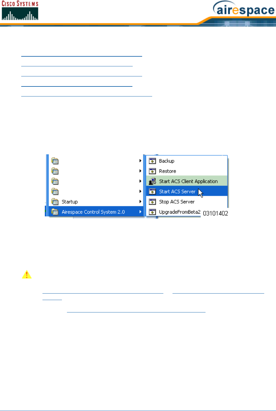
4/1/05 Starting and Stopping Windows Cisco WCS
OL-7426-02
Starting and Stopping Windows Cisco WCSStarting and Stopping Windows Cisco WCS
•Starting Cisco WCS as a Windows Application
•Starting Cisco WCS as a Windows Service
•Stopping the Cisco WCS Windows Application
•Stopping the Cisco WCS Windows Service
•Checking the Cisco WCS Windows Service Status
Starting Cisco WCS as a Windows ApplicationStarting Cisco WCS as a Windows Application
When Cisco WCS has been installed as an application, you can start the Cisco WCS application at any
time.
•From the Windows START button, select the Programs menu, and click Wireless Control
System 2.2/Start WCS Server.
The start Cisco WCS script opens a Start Cisco WCS Server DOS window, which displays
many Created table and Process: Started messages.
When the Start Cisco WCS Server window displays Please connect your client (Cisco WCS User
Interface) to the web server on port 80, Cisco WCS has started and is ready to host Cisco WCS User
Interfaces.
If desired, continue with Starting and Stopping the Cisco WCS Web Interface.
Starting Cisco WCS as a Windows ServiceStarting Cisco WCS as a Windows Service
When Cisco WCS has been installed as a service, you can start the Cisco WCS service at any time.
•From the Windows START button, select the Programs menu, and select Wireless Control
System 2.2/Start WCS Service.
CAUTION: Cisco WCS may display Start Cisco WCS Server, Solid Database, and
Apache windows, which you can minimize. DO NOT CLOSE any of these windows, or
you can abnormally halt Cisco WCS. When you plan to shut down Cisco WCS, refer to
Stopping the Cisco WCS Windows Application or Stopping the Cisco WCS Windows
Service.
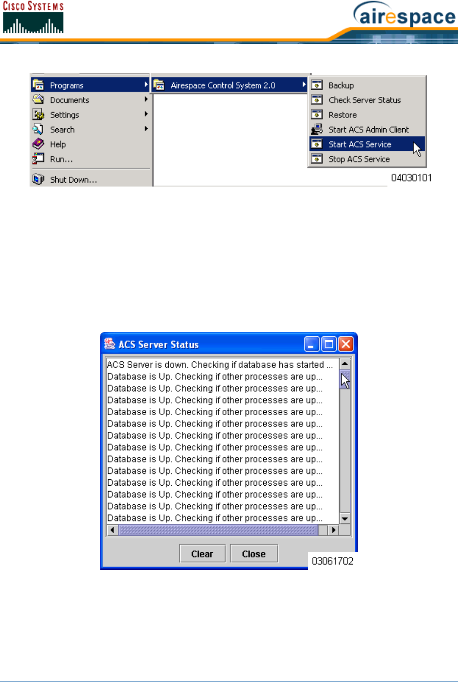
4/1/05 Starting and Stopping Windows Cisco WCS
OL-7426-02
The start Cisco WCS script opens a Start Cisco WCS Service DOS window, which displays the
following messages:
The Nms Server service is starting. . (in the background)
The Nms Server service was started successfully.
Launching Server Status Window
The Start Cisco WCS Service window displays the Cisco WCS Server Status window. You
can close the Start Cisco WCS Service DOS window, and view the current Cisco WCS Service
status in the Cisco WCS Server Status window. When the Start Cisco WCS Service window
displays the Cisco WCS is Up message, Cisco WCS service has started and is ready to host Cisco
WCS User Interfaces.
Note that the Cisco WCS Server Status window is updated about every five seconds. When
the Cisco WCS Server Status window displays the Cisco WCS is Up message, the Cisco WCS
service is ready to host Cisco WCS User Interfaces.

4/1/05 Starting and Stopping Windows Cisco WCS
OL-7426-02
If desired, continue with Starting a Cisco WCS User Interface or Using the Cisco Wireless Control
System in the Product Guide.
Stopping the Cisco WCS Windows ApplicationStopping the Cisco WCS Windows Application
You can stop the Cisco WCS application at any time.
•From the Windows START button, select the Programs menu, and select Cisco Wireless
Control System 2.2/Stop Cisco WCS Server.
The Stop Cisco WCS script opens a Stop Cisco WCS Server DOS window, which displays the
Shutdown Web NMS Server window.
•The Stop Cisco WCS Server window displays the Press any key to continue prompt.
•Press any key to complete the Stop Cisco WCS script.
You have shut down the Cisco WCS application. If desired, continue with the Product Guide.
Stopping the Cisco WCS Windows ServiceStopping the Cisco WCS Windows Service
You can stop the Cisco WCS service at any time.
•From the Windows START button, select the Programs menu, and select Cisco Wireless
Control System 2.2/Stop Cisco WCS Service.
The Stop Cisco WCS script opens a Stop Cisco WCS Service DOS window and halts the Cisco
WCS service.
You have shut down the Cisco WCS service. If desired, continue with the Product Guide.
Checking the Cisco WCS Windows Service StatusChecking the Cisco WCS Windows Service Status
When Cisco WCS is installed as a Service, it runs in the background. That is, it has no windows open, so
you cannot directly view its current status. To allow you to check the Cisco WCS Service status, Cisco
SWAN has provided a convenient Cisco WCS Status utility.
•To activate the Cisco WCS Status utility, from the Windows START button, select the
Programs menu, and select Cisco Wireless Control System/Check Server Status.
The Check Server Status script launches the Start Cisco WCS Service DOS window, which in
turn launches the Cisco WCS Server Status window.
Note: You can close the Cisco WCS Server Status window at any time, if you wish.
When you want to view the current Cisco WCS status, from the Windows START
button, select the Programs menu, and select Cisco Wireless Control System
2.2/Check Server Status to view the Cisco WCS Server Status window again.
Note: If there are any Cisco WCS User Interfaces logged in when you stop the Cisco
WCS Server, the Cisco WCS User Interface sessions stop functioning.
Note: If there are any Cisco WCS User Interfaces logged in when you stop the Cisco
WCS Server, the Cisco WCS User Interface sessions stop functioning.
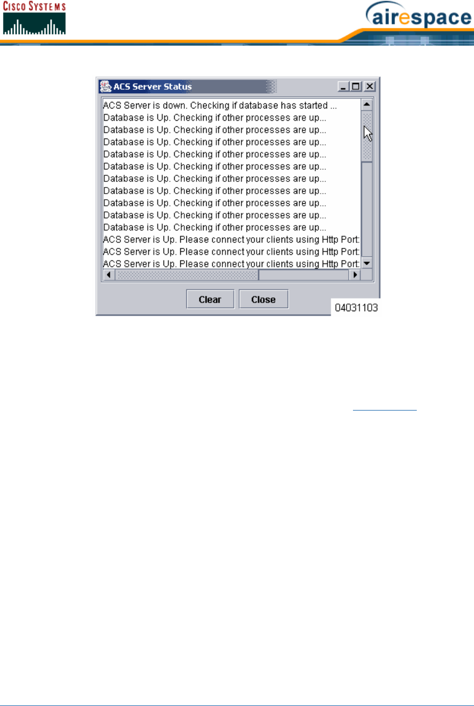
4/1/05 Starting and Stopping Windows Cisco WCS
OL-7426-02
When the Cisco WCS Service is active, the Cisco WCS Server Status window reports that the
Cisco WCS is Up. When the Cisco WCS Service is inactive, the Cisco WCS Server Status
window reports that the Cisco WCS is down. Checking if database has started ...
•You can close the Start Cisco WCS Service DOS window and the Cisco WCS Server Status
window at any time.
You have viewed the Cisco WCS service status. If desired, continue with the Product Guide.

4/1/05 Starting and Stopping Linux Cisco WCS
OL-7426-02
Starting and Stopping Linux Cisco WCSStarting and Stopping Linux Cisco WCS
•Starting the Linux Cisco WCS Application
•Stopping the Linux Cisco WCS Application
•Checking the Linux Cisco WCS Status
Starting the Linux Cisco WCS ApplicationStarting the Linux Cisco WCS Application
Linux Cisco WCS is always installed as an application, and you can start the Linux Cisco WCS applica-
tion at any time.
When Cisco WCS has been installed on the Linux Cisco WCS Server, you can start the Cisco WCS Server
at any time.
•If not already done, log in as root.
•Using the Linux command line interface, navigate to the default /usr/local/bin/WCS22
directory (or the directory chosen during installation).
•Enter ./StartACSServer to start the Cisco WCS Server.
•Enter ./CheckServerStatus to open the Cisco WCS Server Status window.
When the Start Cisco WCS Server Status window displays Cisco WCS Server is up. Please connect your
clients (Cisco WCS User Interfaces) using Http Port: 80 or Https Port: 433 (or whichever HTTP: or
HTTPS: port you selected when installing Cisco WCS), the Cisco WCS Server has started and is ready to
host Cisco WCS User Interfaces.
If desired, continue with Starting and Stopping the Cisco WCS Web Interface.
Stopping the Linux Cisco WCS ApplicationStopping the Linux Cisco WCS Application
You can stop the Cisco WCS Linux application at any time.
•If not already done, log in as root.
•Using the Linux command line interface, navigate to the default /usr/local/bin/WCS22
directory (or the directory chosen during installation).
•Enter ./StopACSServer to stop the Cisco WCS Server application.
You have shut down the Cisco WCS Server application. If desired, continue with the Product Guide.
Checking the Linux Cisco WCS StatusChecking the Linux Cisco WCS Status
You can check the status of the Linux Cisco WCS at any time.
•Using the Linux command line interface, navigate to the default /usr/local/bin/WCS22
directory (or the directory chosen during installation).
•Enter ./CheckServerStatus to view the Cisco WCS Server Status window. The Cisco WCS
Server Status window shows Cisco WCS Server is up. Please connect your clients (Cisco WCS
User Interfaces) using Http Port: 80 or Https Port: 433 when the Cisco WCS Server is
CAUTION: When you plan to shut down the Linux Cisco WCS Server, refer to
Stopping the Linux Cisco WCS Application.
Note: If there are any Cisco WCS User Interfaces logged in when you stop the Cisco
WCS Server, the Cisco WCS User Interface sessions stop functioning.

4/1/05 Starting and Stopping Linux Cisco WCS
OL-7426-02
running. The Cisco WCS Server Status window typically shows Cisco WCS Server is down.
Checking if database has started when the Cisco WCS Server is not running.
•To close the Cisco WCS Server Status window, click Close in the Cisco WCS Server Status
window or enter <CTRL-C> in the ./StartACSServer window.
You have viewed the Cisco WCS service status. If desired, continue with the Product Guide.
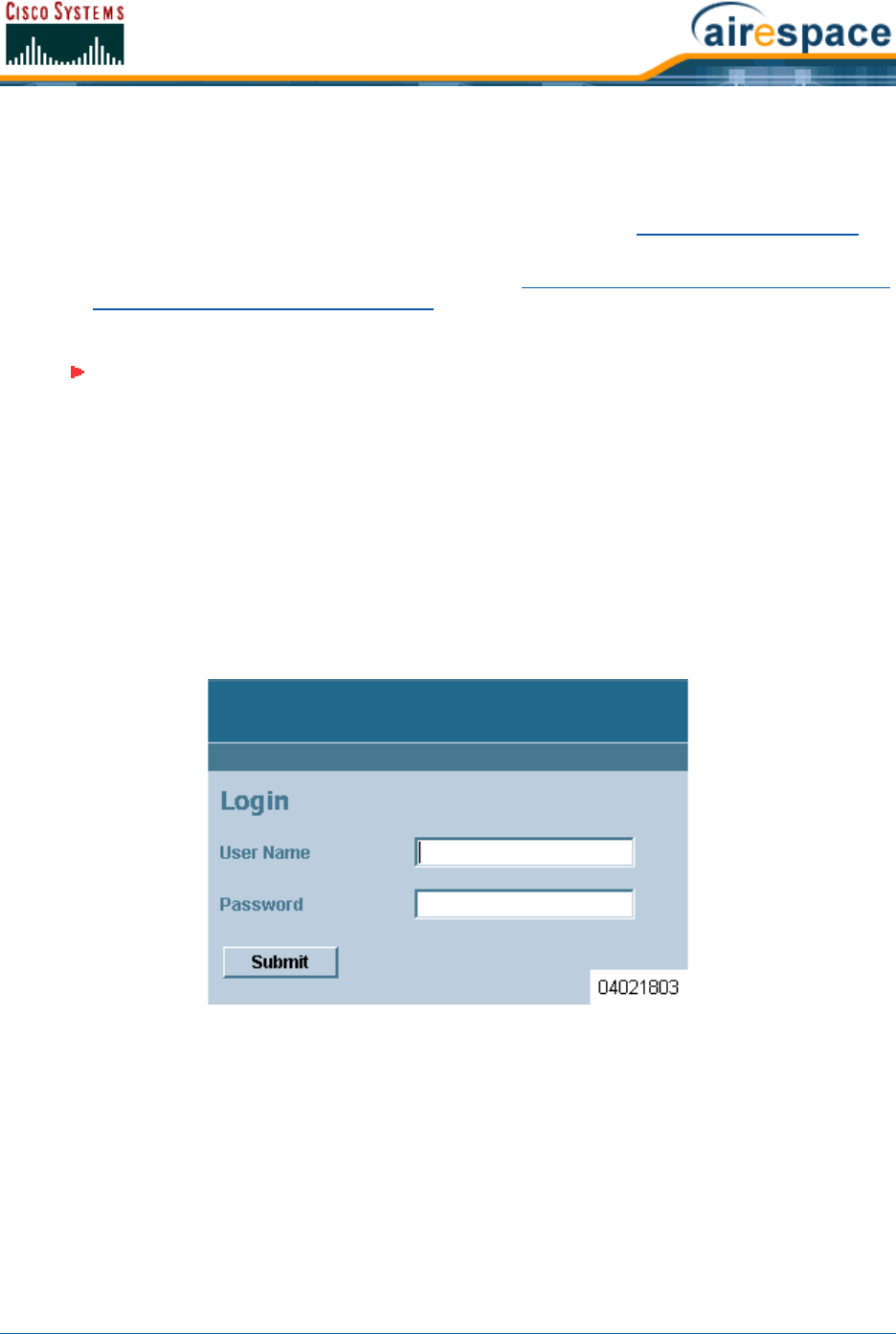
4/1/05 Starting and Stopping the Cisco WCS Web Interface
OL-7426-02
Starting and Stopping the Cisco WCS Web InterfaceStarting and Stopping the Cisco WCS Web Interface
Starting a Cisco WCS User InterfaceStarting a Cisco WCS User Interface
This Cisco WCS interface is used by Cisco WCS operators as described in Cisco WCS User Interface.
Starting a Cisco WCS User Interface is a simple task.
•If not already done, start Cisco WCS as described in Starting and Stopping Windows Cisco WCS
or Starting and Stopping Linux Cisco WCS.
•Launch an Internet Explorer 6.0 (or other Web Browser).
https://<localhost|Cisco WCS IP Address>
--or--
http://<localhost|Cisco WCS IP Address>
where https:// is a secure (http + Secure Sockets Layer) login, to which the Cisco WCS
usually returns a Security Alert message before continuing, and http:// is an unsecure login,
and where localhost is used when the Cisco WCS User Interface is on the Cisco WCS Server,
and where Cisco WCS IP Address is the IP Address of Cisco WCS on any other workstation.
Examples: http://localhost or https://176.89.43.44.
The Cisco WCS User Interface displays the Cisco WCS Login page.
•In the Cisco WCS Login page, enter the following:
-User Name: Your username (default root).
-Password: Your password (default public).
•When you have made these entries in the Cisco WCS Login page, click Submit.
The Cisco WCS User Interface is now active and available for your use, and displays the Network
Summary (Network Dashboard) similar to the following figure, which provides a summary of the Cisco
SWAN, including reported coverage holes, Cisco 1000 Series lightweight access point operational data,
most recent detected rogue APs, and client distribution over time.
Note: Some documented features may not function properly if you choose to use any
Web Browser other than Internet Explorer 6.0 on a Windows workstation.
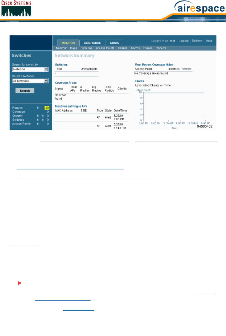
4/1/05 Starting and Stopping the Cisco WCS Web Interface
OL-7426-02
Continue with the Using the Cisco Wireless Control System or Stopping a Cisco WCS User Interface
section.
Stopping a Cisco WCS User InterfaceStopping a Cisco WCS User Interface
•Manually Stopping the Cisco WCS User Interface
•Cisco WCS Shutdown Stopping the Cisco WCS User Interface
Manually Stopping the Cisco WCS User InterfaceManually Stopping the Cisco WCS User Interface
•When you are finished working in the Cisco WCS User Interface application, exit the Cisco WCS
User Interface application page by clicking Logout in the upper right corner of the Cisco WCS
User Interface page. The Cisco WCS User Interface displays the Cisco WCS Login page.
Note that you can return to the previous cached screen in the Web Browser. However, if you
attempt to access any of the parameters in that screen, you are returned to the Cisco WCS
Login page.
•Alternatively, you can shut down the Web Browser.
The Cisco WCS User Interface window shuts down, leaving Cisco WCS running. If desired, continue with
the Product Guide.
Cisco WCS Shutdown Stopping the Cisco WCS User InterfaceCisco WCS Shutdown Stopping the Cisco WCS User Interface
Occasionally, the system administrator may stop the Cisco WCS Server while a Cisco WCS User
Interface is logged in. Should this happen, the Web Browser displays a The page cannot be displayed
message.
If desired, continue with the Product Guide.
Note: When the Cisco WCS User Interface has been stopped by a Cisco WCS Server
shutdown, it does not reassociate with Cisco WCS when the Cisco WCS Server
restarts. You must restart the Cisco WCS User Interface as described in Starting a
Cisco WCS User Interface.
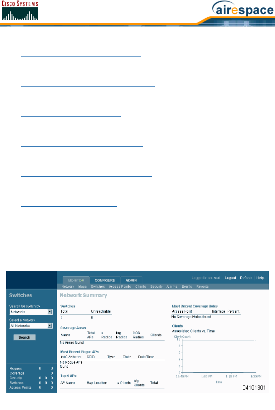
4/1/05 Using Cisco WCS
OL-7426-02
Using Cisco WCSUsing Cisco WCS
•Checking the Cisco SWAN Network Summary
•Adding a Cisco Wireless LAN Controller to Cisco WCS
•Creating an RF Calibration Model
•Adding a Campus Map to the Cisco WCS Database
•Adding a Building to a Campus
•Adding a Standalone Building to the Cisco WCS Database
•Adding an Outdoor Area to a Campus
•Adding Floor Plans to a Campus Building
•Adding Floor Plans to a Standalone Building
•Adding APs to Floor Plan and Open Area Maps
•Monitoring Predicted Coverage (RSSI)
•Monitoring Channels on a Floor Map
•Monitoring Transmit Power Levels on a Floor Map
•Monitoring Coverage Holes on a Floor Map
•Monitoring Users on a Floor Map
•Monitoring Clients From a Floor Map
Checking the Cisco SWAN Network SummaryChecking the Cisco SWAN Network Summary
When you use Cisco WCS for the first time, the Network Summary page shows that the Cisco Wireless
LAN Controllers, Coverage Areas, Most Recent Rogue APs, Top Five Cisco 1000 Series lightweight
access points, and the Most Recent Coverage Holes database is empty, as shown in the following figure.
The following figure also shows that there are no Clients connected to the Cisco SWAN at this time.
Figure - Network Summary for Unconfigured Cisco WCS Database
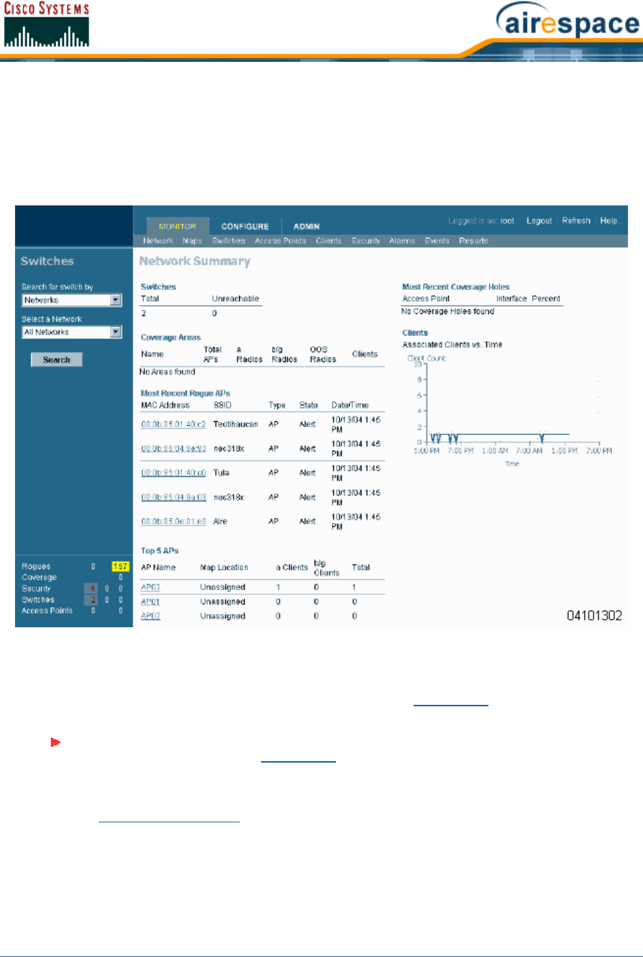
4/1/05 Adding a Cisco Wireless LAN Controller to Cisco WCS
OL-7426-02
After you have configured the Cisco WCS database with one or more Cisco Wireless LAN Controllers,
the Network Summary page shows that the Cisco Wireless LAN Controllers, Coverage Areas, Most
Recent Rogue APs, the Top Five Cisco 1000 Series lightweight access points, and the Top Five Coverage
Holes databases are updated, as shown in the following figure. The following figure also shows that
there has been one Client connected to the Cisco SWAN over the last 24 hours.
Figure - Network Summary for Configured Cisco WCS Database
Adding a Cisco Wireless LAN Controller to Cisco WCSAdding a Cisco Wireless LAN Controller to Cisco WCS
When you know the IP Address of a Cisco Wireless LAN Controller Service Port or name, do the
following to add the Cisco Wireless LAN Controller to the Cisco WCS database.
•Select Configure/Controllers to have Cisco WCS display the All Controllers page.
Note: Cisco SWAN recommends that you manage Cisco Wireless LAN Controllers via
the dedicated front-panel Service Port for improved security. When you are
managing a Cisco Wireless LAN Controller that has its Service port disabled, and
when you are managing a Cisco 2000 Series Wireless LAN Controller (which has no
Service Port), you must manage the Cisco Wireless LAN Controller through its
Management Interface.
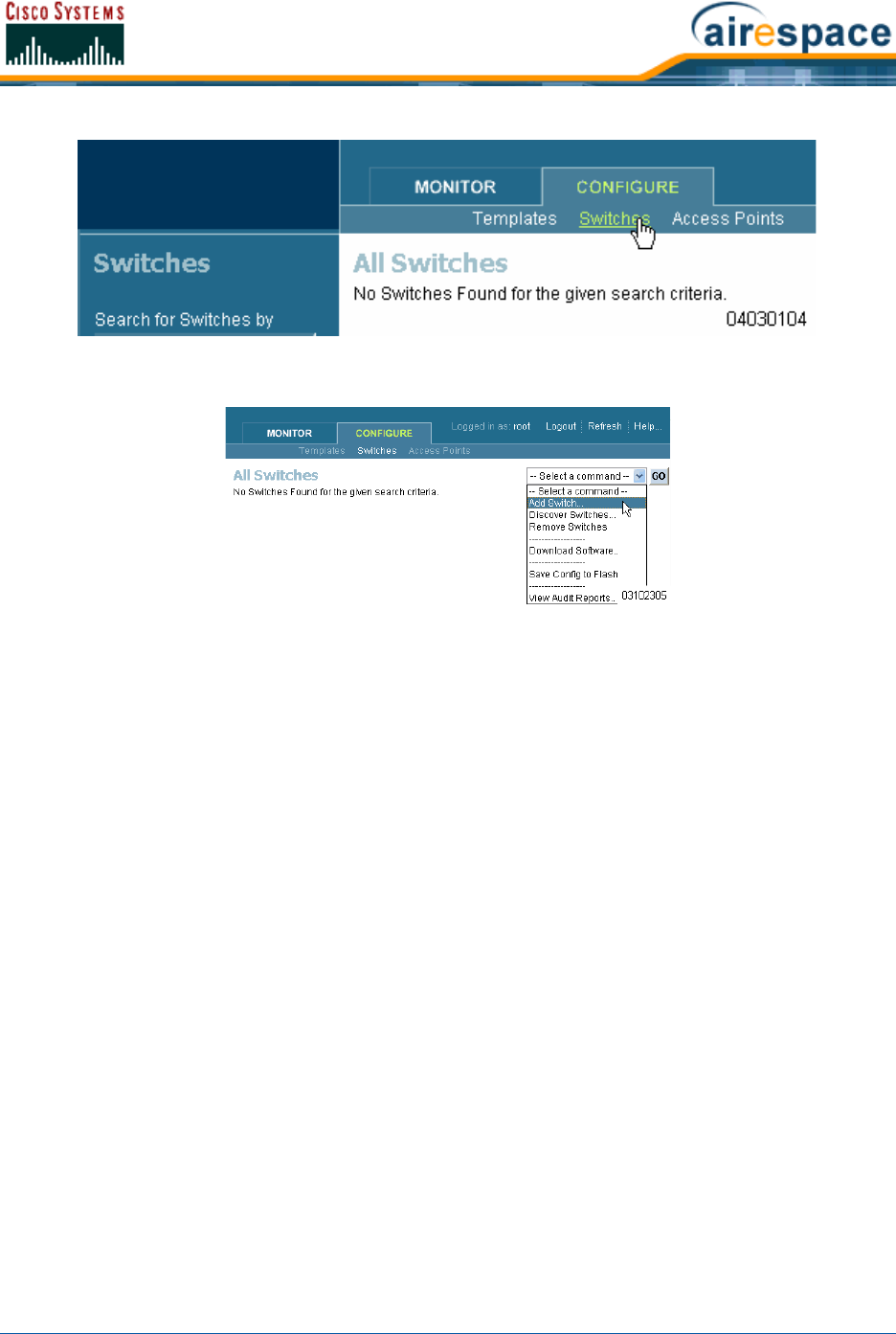
4/1/05 Adding a Cisco Wireless LAN Controller to Cisco WCS
OL-7426-02
•In the Button Area, select Add Controller.
•Click GO to have the Cisco WCS User Interface display the Add Controller page.
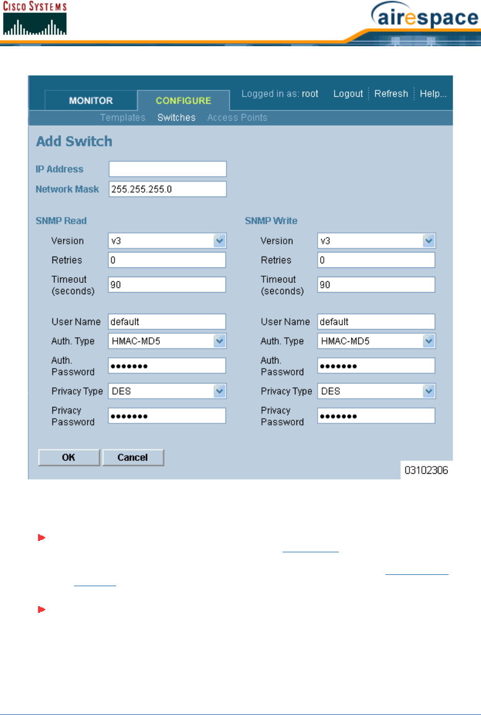
4/1/05 Adding a Cisco Wireless LAN Controller to Cisco WCS
OL-7426-02
•Enter the Cisco Wireless LAN Controller IP Address, Network Mask, and required SNMP settings
in the Add Controller data entry fields.
•Click OK, and the Cisco WCS User Interface displays the Please wait. . . dialog screen while it
contacts the Cisco Wireless LAN Controller, adds the current Cisco Wireless LAN Controller
configuration to the Cisco WCS database, and then returns you to the Add Controller page.
Note: Cisco SWAN recommends that you manage each Cisco 4100 Series Wireless
LAN Controller via the dedicated front-panel Service Port for highest security. If any
Cisco 4100 Series Wireless LAN Controller has its Service port disabled, you will
manage the Cisco 4100 Series Wireless LAN Controller through its Management
Interface.
Note: Cisco Wireless LAN Controllers are factory-configured with SNMP Version 2C
enabled, which is the most secure and slowest version. After you have logged into
the Cisco Wireless LAN Controller, you can change the SNMP parameters and re-add
the Cisco Wireless LAN Controller to the Cisco WCS database.
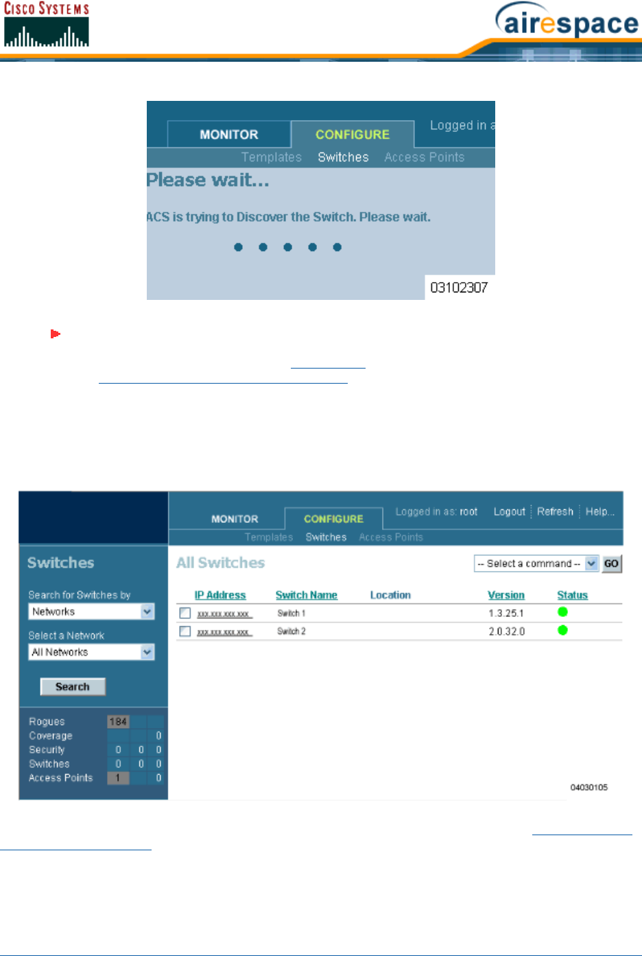
4/1/05 Adding a Cisco Wireless LAN Controller to Cisco WCS
OL-7426-02
•You may now add additional Cisco Wireless LAN Controllers in the Add Controller page, or
click the Configure Tab to have the Cisco WCS User Interface display the All Controllers page.
You have added Cisco Wireless LAN Controllers to the Cisco WCS database. Continue Using the Cisco
Wireless Control System.
Note: If Cisco WCS does not find a Cisco Wireless LAN Controller at the selected IP
Address, the Discovery Status page displays a No response from device, check
SNMP. . . message. Either the Service Port IP Address is set incorrectly (refer to
Configuring Other Ports and Parameters), or Cisco WCS was unable to contact the
Cisco Wireless LAN Controller (be sure that you can ping the Cisco Wireless LAN
Controller from the Cisco WCS Server and retry), or the device has different SNMP
settings (verify that the SNMP settings match and retry).
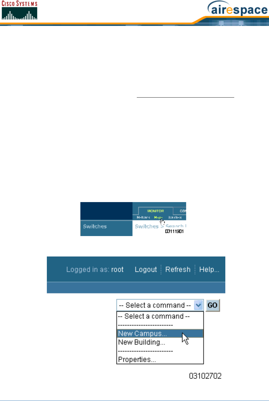
4/1/05 Creating an RF Calibration Model
OL-7426-02
Creating an RF Calibration ModelCreating an RF Calibration Model
When you are using Cisco Wireless Control System with Location Services and want to improve client
and rogue AP location accuracy across one or more floors, you can create an RF Calibration Model that
uses manually collected RF measurements to calibrate the location algorithm.
When you have multiple floors in a building with the same physical layout as the calibrated floor, you
can save time calibrating the remaining floors by applying the same RF Calibration Model to the
remaining floors.
Follow the RF Calibration procedures included in the Cisco WCS Web Interface Online Help to create an
RF Prediction Model.
Adding a Campus Map to the Cisco WCS DatabaseAdding a Campus Map to the Cisco WCS Database
Rather than forcing the Network operator to use only a text-based map to manage the Cisco Structured
Wireless-Aware Network (Cisco SWAN), Cisco WCS allows the operator to view the managed System on
realistic campus, building, and floor plan maps. This section describes how to add a single campus map
to the Cisco WCS database.
•First, save your maps in .PNG, .JPG, .JPEG, or .GIF format. They can be any size, as Cisco WCS
automatically resizes the map to fit in its working areas.
•Browse to and import the map(s) from anywhere in your file system.
•Select the Monitor Tab.
•Click Maps to have Cisco WCS display the Maps page.
•In the Button Area, select New Campus.
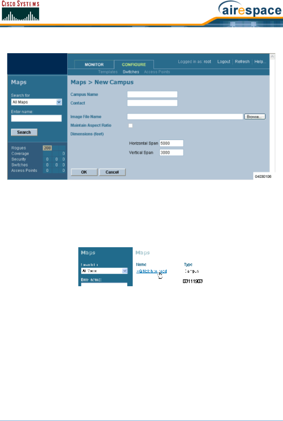
4/1/05 Adding a Campus Map to the Cisco WCS Database
OL-7426-02
•Click GO to have the Cisco WCS User Interface display the Maps > New Campus page.
•In the Maps > New Campus page, enter the Campus Name and Campus Contact Information,
click Browse to search for and select the Campus graphic name, select Maintain Aspect Ratio (if
desired), and enter the Horizontal Span and the Vertical Span of the map in feet. (Note that the
Campus Horizontal Span and the Vertical Span should be larger than any building or floor plan
to be added to the campus.)
•Click OK to add the Campus Map to the Cisco WCS database. The Cisco WCS User Interface
displays the Maps page.
The Maps page contains a current list of Campus Names, the map type (Campus or Building),
and the current Campus Status (Green for OK, Red for Failure, Amber for Alarm).
•You have added a map to the Cisco WCS database, which corresponds to a single Campus.
•Ensure that the graphic has been added correctly by clicking the new Campus Name to have
the Cisco WCS User Interface display the Maps > <Campus Name> page as shown in the
following figure.
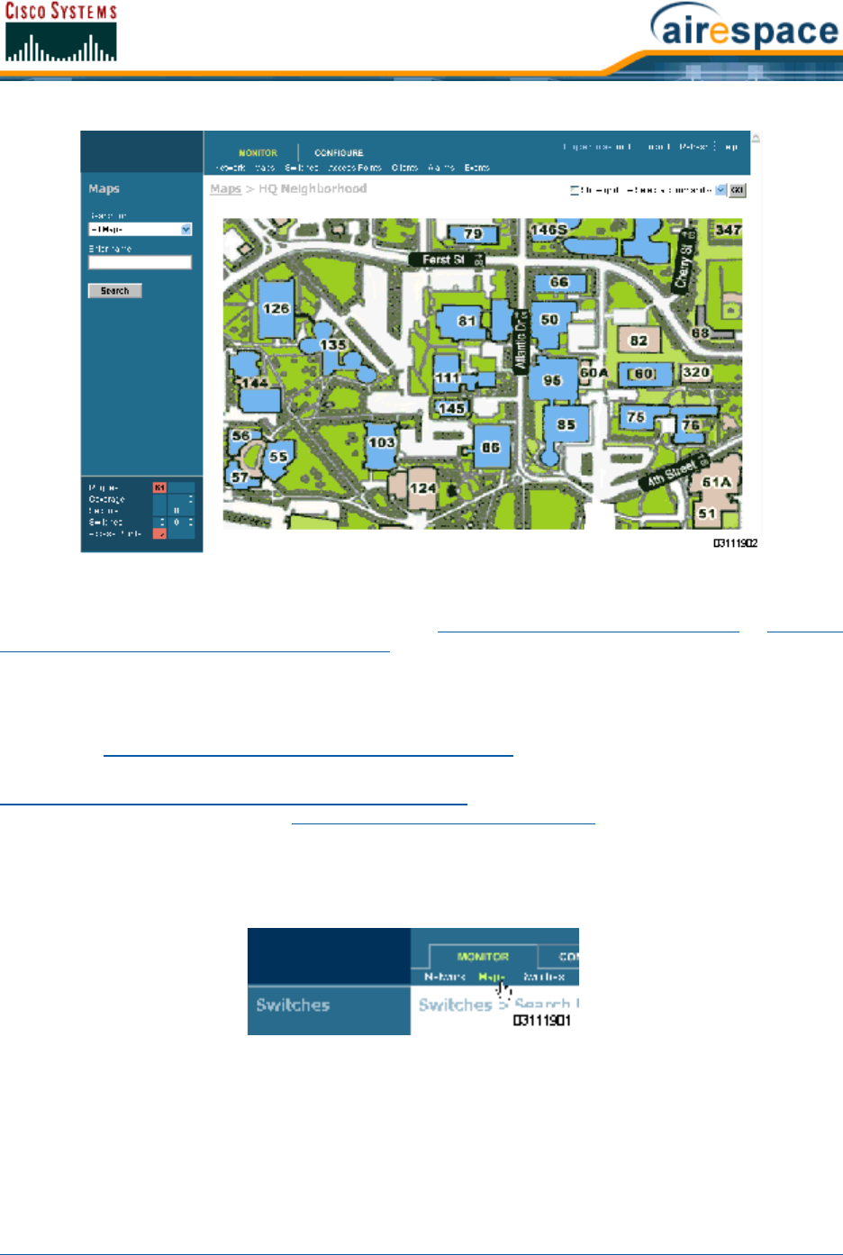
4/1/05 Adding a Building to a Campus
OL-7426-02
•Repeat this section for any remaining Campuses.
When you have completed this section, continue with Adding an Outdoor Area to a Campus or Adding a
Standalone Building to the Cisco WCS Database.
Adding a Building to a CampusAdding a Building to a Campus
You can add Buildings to the Cisco WCS database whether or not you have added maps or Campuses as
described in Adding a Campus Map to the Cisco WCS Database.
To add a Building to the Cisco WCS database without associating it with a Campus, continue with
Adding a Standalone Building to the Cisco WCS Database. To add an Outdoor Area to a Campus in the
Cisco WCS database, continue with Adding an Outdoor Area to a Campus. Otherwise, add a Building to
a Campus in the Cisco WCS database by performing the following steps:
•Select the Monitor Tab.
•Click Maps to have Cisco WCS display the Maps page.
•In the Maps Page, select the desired Campus.
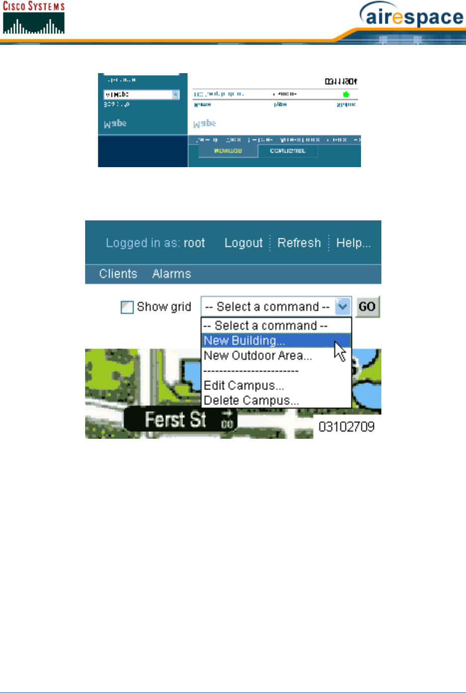
4/1/05 Adding a Building to a Campus
OL-7426-02
The Cisco WCS User Interface displays the Maps > <Campus Name> page.
•In the Maps > <Campus Name> page Button Area, select New Building.
•Click GO to have the Cisco WCS User Interface display the <Campus Name> > New
Building page.
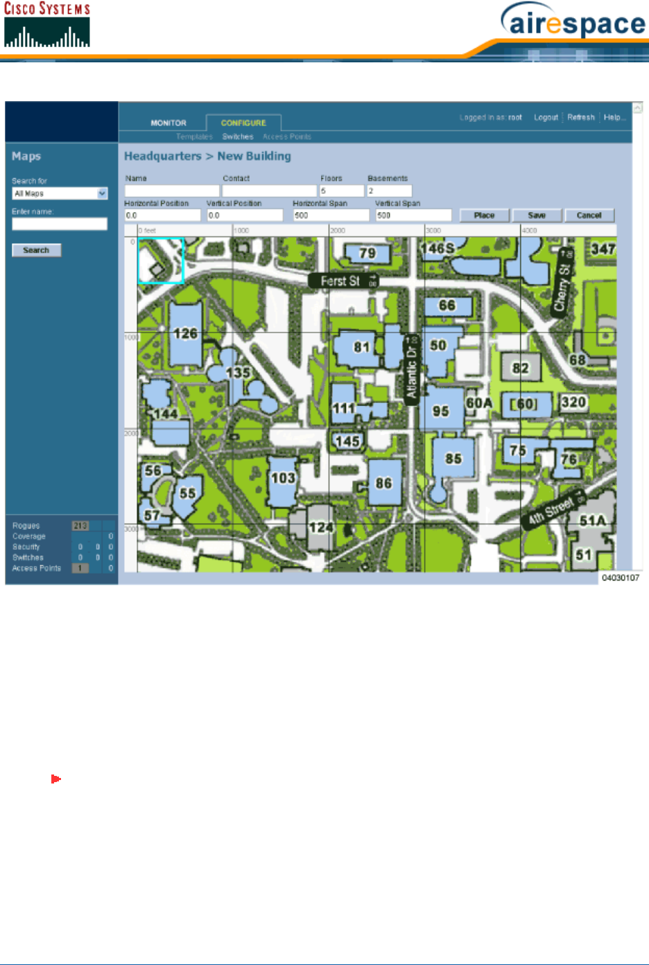
4/1/05 Adding a Building to a Campus
OL-7426-02
•In the <Campus Name> > New Building page, you can create a virtual Building to organize
related Floor Plan maps. To do this:
-Enter the Building Name.
-Enter the Building Contact Name.
-Enter the number of Floors and Basements.
-Enter an approximate Building Horizontal Span and Vertical Span (width and depth on
the map) in feet. Note that these numbers should be larger than or the same size as
any floors that might be added later.
-Click Place to locate the Building on the Campus map. Cisco WCS creates a Building
rectangle scaled to the size of the Campus map.
-Left-click on the Building rectangle and drag it to the desired position on the Campus
map.
Note: Alternatively, you can use <CTRL-Left-Click> to resize the bounding area in
the upper left corner of the Campus map. As you change the size of the bounding
area, the Building Horizontal Span and Vertical Span parameters vary to match your
changes.
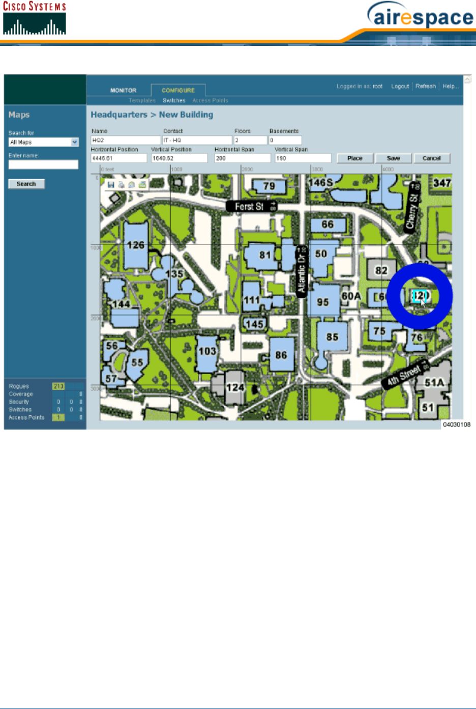
4/1/05 Adding a Building to a Campus
OL-7426-02
-Click Save to save the Building definition and its Campus location in the Cisco WCS
database. Cisco WCS saves the Building name in the Building rectangle on the Campus
map. Note that there will be a hyperlink associated with the Building that takes you to
the corresponding Map page.
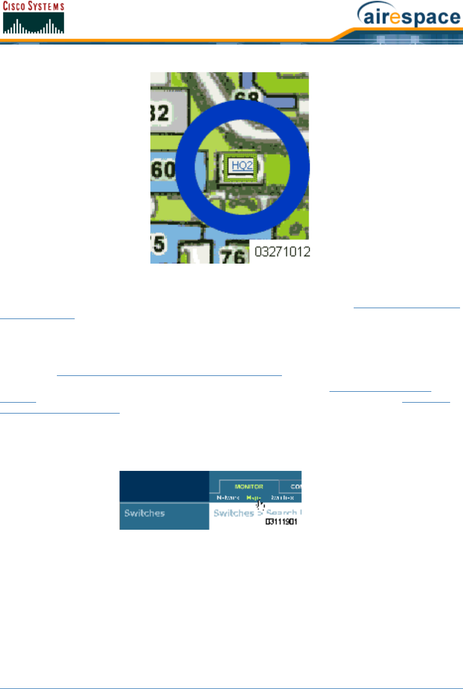
4/1/05 Adding a Standalone Building to the Cisco WCS Database
OL-7426-02
•Repeat this section for any remaining Campus Buildings.
When you have completed this section for all Campus Buildings, continue with Adding Floor Plans to a
Campus Building.
Adding a Standalone Building to the Cisco WCS DatabaseAdding a Standalone Building to the Cisco WCS Database
You can add Buildings to the Cisco WCS database whether or not you have added maps or Campuses as
described in Adding a Campus Map to the Cisco WCS Database.
To add a building to a Campus in the Cisco WCS database, continue with Adding a Building to a
Campus. To add an Outdoor Area to a Campus in the Cisco WCS database, continue with Adding an
Outdoor Area to a Campus. Otherwise, add a standalone building to a Campus by performing the
following steps:
•Select the Monitor Tab.
•Click Maps to have Cisco WCS display the Maps page.
•In the Button Area, select New Building.
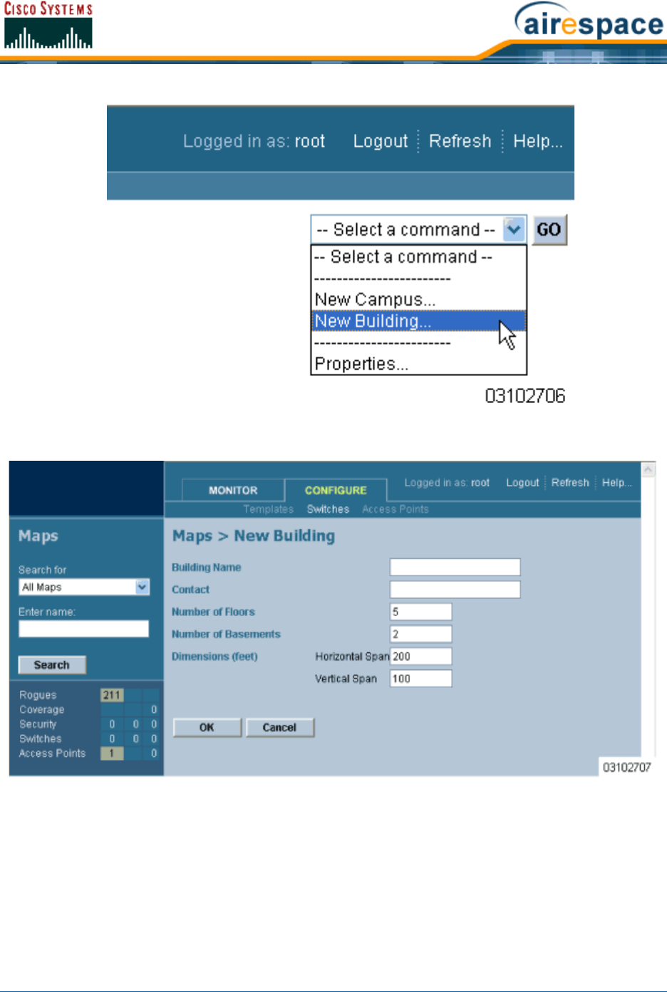
4/1/05 Adding a Standalone Building to the Cisco WCS Database
OL-7426-02
•Click GO to have the Cisco WCS User Interface display the Maps > New Building page.
•In the Maps > New Building page, you can create a virtual Building to organize related Floor
Plan maps. To do this:
-Enter the Building Name.
-Enter the Building Contact Name.
-Enter the number of Floors and Basements.
-Enter an approximate Building Horizontal Span and Vertical Span (width and depth on
the map) in feet. Note that these numbers should be larger than or the same as any
floors that might be added later.
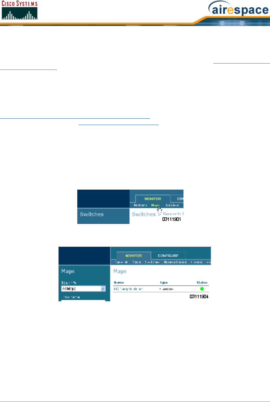
4/1/05 Adding an Outdoor Area to a Campus
OL-7426-02
-Click OK to save the Building definition to the Cisco WCS database.
•Repeat this section for any remaining Standalone Buildings.
When you have completed this section for all Standalone Buildings, continue with Adding Floor Plans to
a Standalone Building.
Adding an Outdoor Area to a CampusAdding an Outdoor Area to a Campus
You can add Outdoor Areas to a Campus in the Cisco WCS database whether or not you have added
Outdoor Area maps to the Cisco WCS database.
To add a building to the Cisco WCS database without associating it with a Campus, continue with
Adding a Standalone Building to the Cisco WCS Database. To add a building to a Campus in the Cisco
WCS database, continue with Adding a Building to a Campus. Otherwise, add an Outdoor Area to a
Campus by performing the following steps:
•If desired, save Outdoor Area maps in .PNG, .JPG, .JPEG, or .GIF format. Note that you do not
need to have a map for the Outdoor Area map(s). The maps can be any size, as Cisco WCS
automatically resizes the map(s) to fit in its working areas.
•Browse to and import the map(s) from anywhere in your file system.
•Select the Monitor Tab.
•Click Maps to have Cisco WCS display the Maps page.
•In the Maps Page, select the desired Campus.
The Cisco WCS User Interface displays the Maps > <Campus Name> page.
•In the Maps > <Campus Name> page Button Area, select New Outdoor Area.
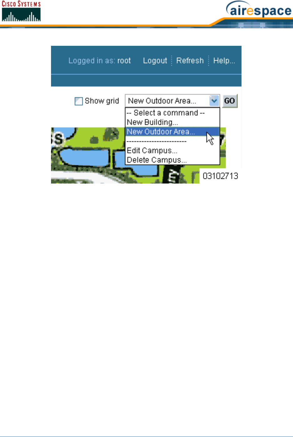
4/1/05 Adding an Outdoor Area to a Campus
OL-7426-02
•Click GO to have the Cisco WCS User Interface display the <Campus Name> > New
Outdoor Area page.
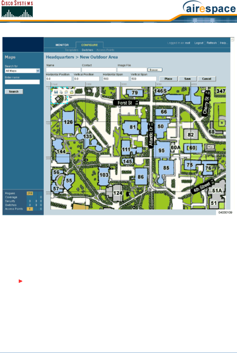
4/1/05 Adding an Outdoor Area to a Campus
OL-7426-02
•In the <Campus Name> > New Outdoor Area page, you can create a manageable Outdoor
Area. To do this:
-Enter the Outdoor Area Name.
-Enter the Outdoor Area Contact Name.
-Enter the Outdoor Area Map filename (optional).
-Enter an approximate Outdoor Area Horizontal Span and Vertical Span (width and
depth on the map) in feet.
-Click Place to locate the Outdoor Area on the Campus map. Cisco WCS creates an
Outdoor Area rectangle scaled to the size of the Campus map.
-Left-click on the Outdoor Area rectangle and drag it to the desired position on the
Campus map.
-Click Save to save the Outdoor Area definition and its Campus location in the Cisco
WCS database. Cisco WCS saves the Outdoor Area name in the Outdoor Area rectangle
Note: Alternatively, you can use <CTRL-Left-Click> to resize the bounding area in
the upper left corner of the Campus map. As you change the size of the bounding
area, the Building Horizontal Span and Vertical Span parameters vary to match your
changes.
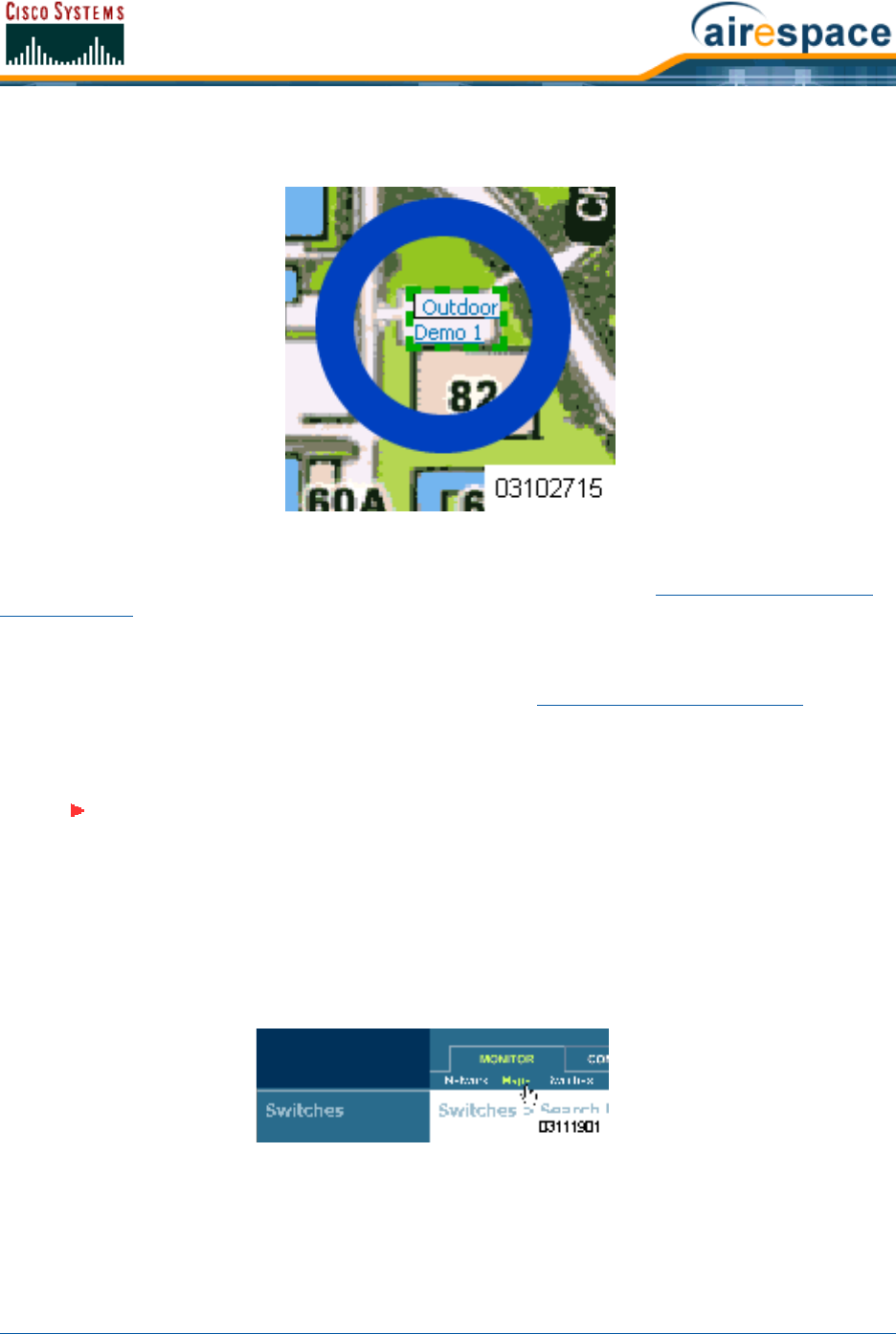
4/1/05 Adding Floor Plans to a Campus Building
OL-7426-02
on the Campus map. Note that there will be a hyperlink associated with the Building
Name or Outdoor Area.
•Repeat this section for any remaining Outdoor Areas.
When you have completed this section for all Outdoor Areas, continue with Using the Cisco Wireless
Control System.
Adding Floor Plans to a Campus BuildingAdding Floor Plans to a Campus Building
Once you have added a Building to a Campus as described in Adding a Building to a Campus, you can
add individual floor plan and basement maps to the Building. Proceed with the following:
•If not already done, save your floor plan map(s) in .FPE, .PNG, .JPG, or .GIF format. They can
be any size, as Cisco WCS automatically resizes the map(s) to fit in its working areas.
•Browse to and import the map(s) from anywhere in your file system.
•Select the Monitor Tab.
•Click Maps to have Cisco WCS display the Maps page.
•In the Maps Page, select the desired Campus.
Note: When you are importing a .FPE floor plan map, you will also need to import a
corresponding .PNG, .JPG, or .GIF format floor plan map. Importing the .PNG, .JPG,
or .GIF format floor plan map allows Cisco WCS to correctly display the floor plan,
and importing the .FPE floor plan map allows Cisco WCS to properly adjust the RF
signal strengths as modified by the walls and other RF obstructions.
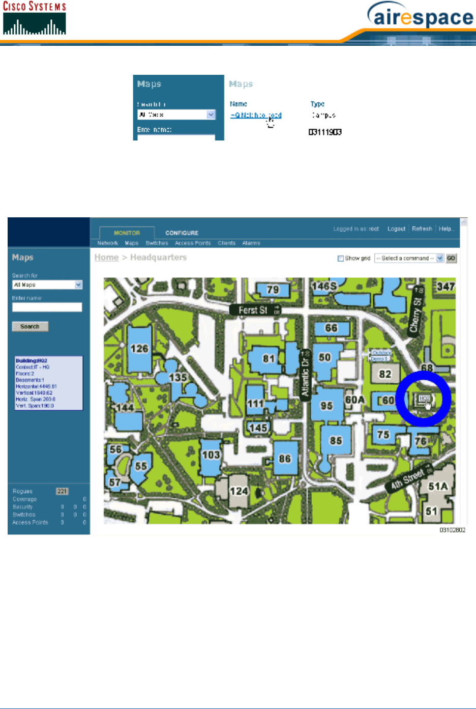
4/1/05 Adding Floor Plans to a Campus Building
OL-7426-02
The Cisco WCS User Interface displays the Maps > <Campus Name> page.
•In the Maps > <Campus Name> page Button Area, move the cursor over an existing
Building rectangle to highlight it. Note that when you highlight the Building rectangle, the
Building description appears in the Sidebar area.
•Left-click on the Building rectangle to have Cisco WCS display the Maps > <Campus Name>
> <Building Name> page.
•In the Button Area, select New Floor Area.
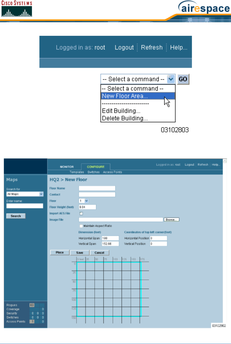
4/1/05 Adding Floor Plans to a Campus Building
OL-7426-02
•Click GO to have the Cisco WCS User Interface display the <Building Name> > New Floor
page.

4/1/05 Adding Floor Plans to a Campus Building
OL-7426-02
•In the <Building Name> > New Floor page, you can add floors to a Building to organize
related Floor Plan maps. To do this:
-Enter the Floor or Basement Name.
-Enter the Floor or Basement Contact Name.
-Select the Floor or Basement number.
-Enter the Floor-to-Floor Height in feet.
-Also, when you are importing a .FPE floor plan map file from the Floor Plan Editor, click
Browse to search for and select the desired .FPE Floor or Basement graphic name.
-In all cases, click Browse to search for and select the desired Floor or Basement
graphic name. Note that when you select the Floor or Basement graphic, Cisco WCS
displays the graphic in the Building-sized grid.
-Enter an approximate Floor or Basement Horizontal Span and Vertical Span (width and
depth on the map) in feet. Note that these numbers should be smaller than or the same
as the Building Horizontal Span and Vertical Span in the Cisco WCS database.
-If necessary, click Place to locate the Floor or Basement graphic on the Building grid.
-Click Save to save the Building definition to the Cisco WCS database. The Cisco WCS
User Interface displays the floor plan graphic in the Maps > <Campus Name> >
<Building Name> page.
Note: You can use <CTRL-Left-Click> to resize the graphic within the
Building-sized grid. Leave Maintain Aspect Ratio checked to preserve the original
graphic aspect ratio, or uncheck the Maintain Aspect Ratio box to change the graphic
aspect ratio. Once again, use <CTRL-Left-Click> to change the graphic aspect
ratio.
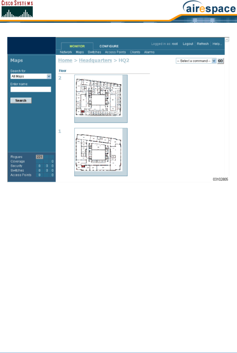
4/1/05 Adding Floor Plans to a Campus Building
OL-7426-02
•In the Maps > <Campus Name> > <Building Name> page, left-click any of the Floor or
Basement images to view the floor plan or basement map as shown in the following figure. Note
that you can zoom in and out to view the map at different sizes, and can add APs from this
page.
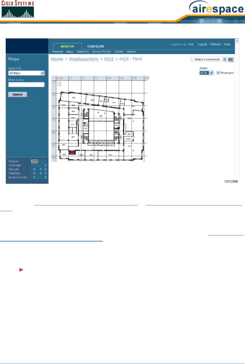
4/1/05 Adding Floor Plans to a Standalone Building
OL-7426-02
•Repeat this section for any remaining Floors or Basements.
Continue with Adding Floor Plans to a Standalone Building or Adding APs to Floor Plan and Open Area
Maps.
Adding Floor Plans to a Standalone BuildingAdding Floor Plans to a Standalone Building
Once you have added a standalone Building to the Cisco WCS database as described in Adding a Stan-
dalone Building to the Cisco WCS Database, you can add individual floor plan maps to the Building.
Proceed with the following:
•If not already done, save your floor plan map(s) in .FPE, .PNG, .JPG, or .GIF format. They can
be any size, as Cisco WCS automatically resizes the map(s) to fit in its working areas.
•Browse to and import the map(s) from anywhere in your file system.
•Select the Monitor Tab.
•Click Maps to have Cisco WCS display the Maps page.
Note: When you are importing a .FPE floor plan map, you will also need to import a
corresponding .PNG, .JPG, or .GIF format floor plan map. Importing the .PNG, .JPG,
or .GIF format floor plan map allows Cisco WCS to correctly display the floor plan,
and importing the .FPE floor plan map allows Cisco WCS to properly adjust the RF
signal strengths as modified by the walls and other RF obstructions.
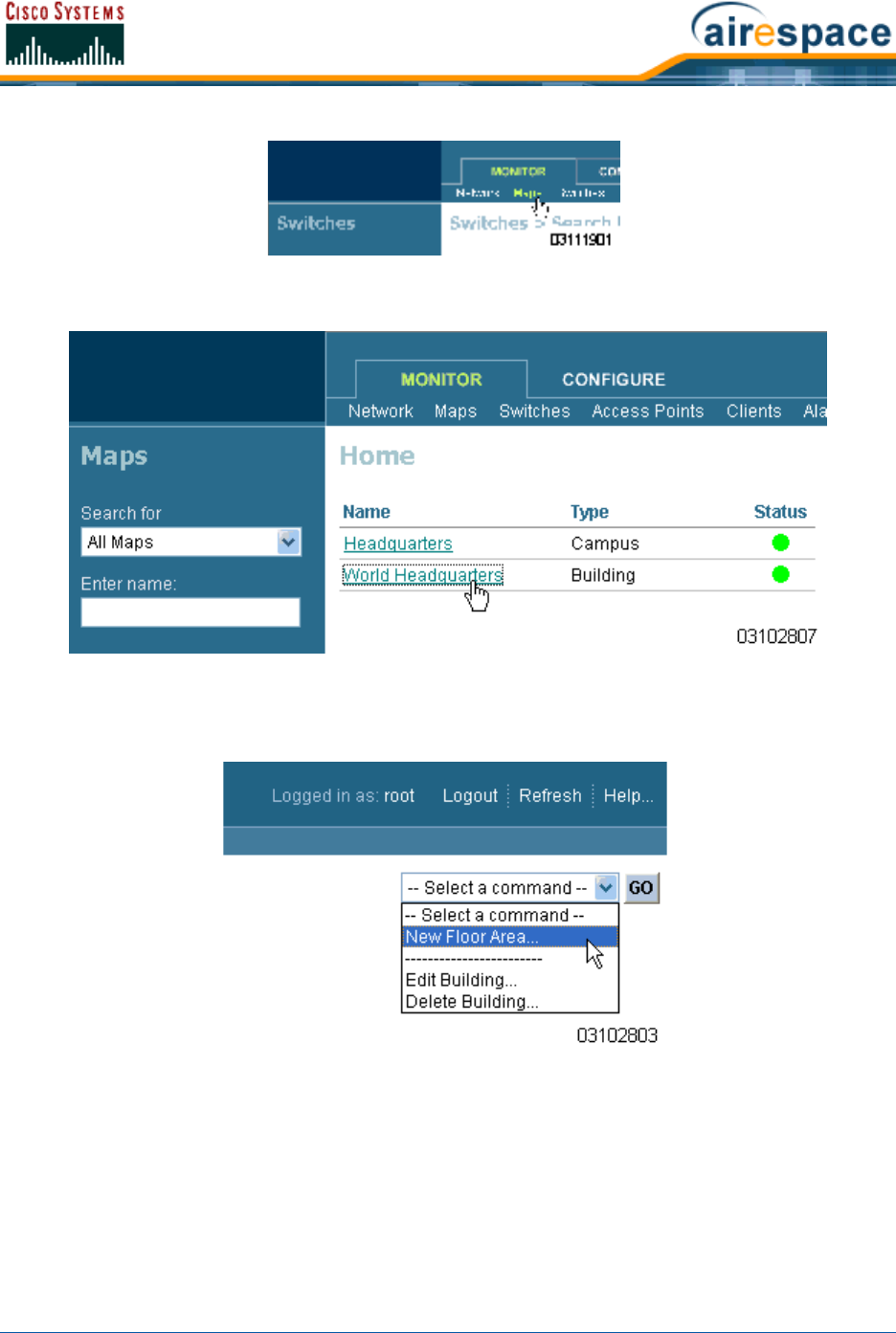
4/1/05 Adding Floor Plans to a Standalone Building
OL-7426-02
•In the Main Data Page, select the desired Building.
The Cisco WCS User Interface displays the Maps > <Building Name> page.
•In the Button Area, select New Floor Area.
•Click GO to have the Cisco WCS User Interface display the <Building Name> > New Floor
page.
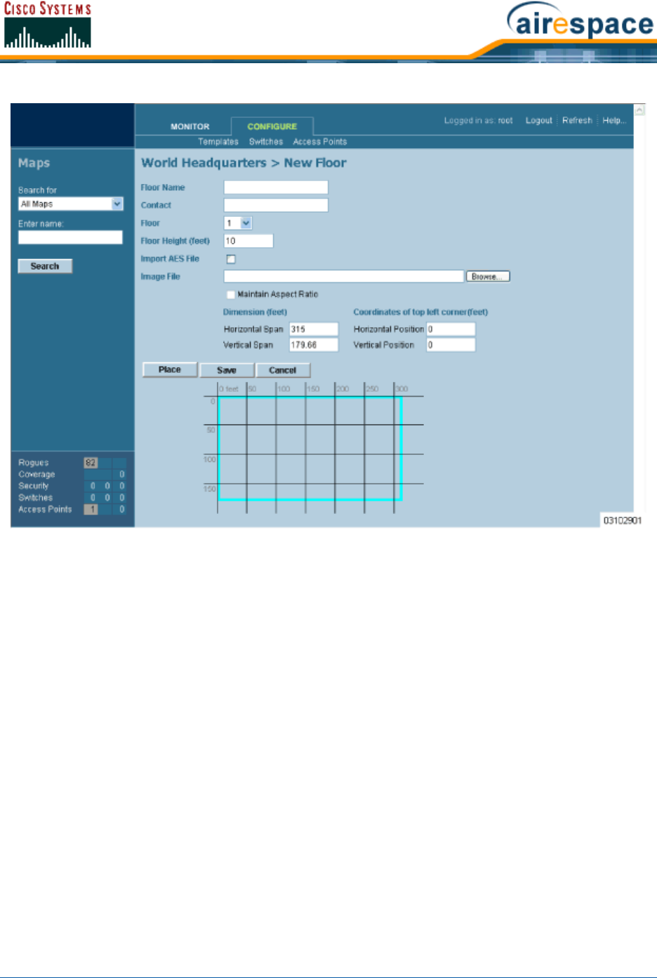
4/1/05 Adding Floor Plans to a Standalone Building
OL-7426-02
•In the <Building Name> > New Floor page, you can add floors to a Building to organize
related Floor Plan maps. To do this:
-Enter the Floor or Basement Name.
-Enter the Floor or Basement Contact Name.
-Select the Floor or Basement number.
-Enter the Floor-to-Floor Height in feet.
-If you are importing a .FPE floor plan map file from the Floor Plan Editor, check the
Import FPE File box. Otherwise, leave this box unchecked.
Also, when you are importing a .FPE floor plan map file from the Floor Plan Editor, click
Browse to search for and select the .FPE desired Floor or Basement graphic name.
-In all cases, click Browse to search for and select the desired Floor or Basement
graphic name. Note that when you select the Floor or Basement graphic, Cisco WCS
displays the graphic in the Building-sized grid.
-Enter an approximate Floor or Basement Horizontal Span and Vertical Span (width and
depth on the map) in feet. Note that these numbers should be smaller than or the same
as the Building Horizontal Span and Vertical Span in the Cisco WCS database.
-If necessary, click Place to locate the Floor or Basement graphic on the Building grid.
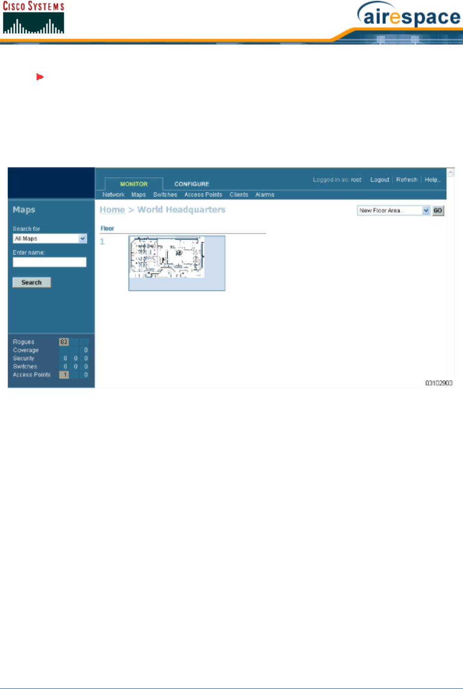
4/1/05 Adding Floor Plans to a Standalone Building
OL-7426-02
-Click Save to save the Building definition to the Cisco WCS database. The Cisco WCS
User Interface displays the floor plan graphic in the Maps > <Building Name> page.
•In the Maps > <Building Name> page, left-click any of the Floor or Basement images to view
the floor plan or basement map as shown in the following figure. Note that you can zoom in and
out to view the map at different sizes, and can add APs from this page.
Note: You can use <CTRL-Left-Click> to resize the graphic within the
Building-sized grid. Leave Maintain Aspect Ratio checked to preserve the original
graphic aspect ratio, or uncheck the Maintain Aspect Ratio box to change the graphic
aspect ratio. Once again, use <CTRL-Left-Click> to change the graphic aspect
ratio.
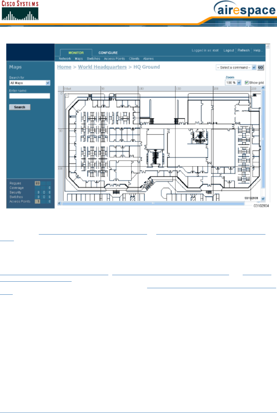
4/1/05 Adding APs to Floor Plan and Open Area Maps
OL-7426-02
•Repeat this section for any remaining Floors or Basements.
Continue with Adding Floor Plans to a Campus Building or Adding APs to Floor Plan and Open Area
Maps.
Adding APs to Floor Plan and Outdoor Area MapsAdding APs to Floor Plan and Open Area Maps
This procedure assumes that you have added the Floor Plan and/or Outdoor Area maps as described in
Adding Floor Plans to a Campus Building, Adding Floor Plans to a Standalone Building and Adding an
Outdoor Area to a Campus. This procedure also assumes that you have added Cisco Wireless LAN
Controllers to the Cisco WCS database as described in Adding a Cisco Wireless LAN Controller to Cisco
WCS before continuing.
After you have added the .FPE and/or .PNG, .JPG, or .GIF format Floor Plan and Outdoor Area
(Coverage Area) maps and Cisco Wireless LAN Controllers to the Cisco WCS database, you can position
Cisco 1000 Series lightweight access point icons on the Cisco WCS maps to show where they are
installed in the Buildings.
Add APs to the Coverage Area maps as follows:
•Select the Monitor Tab.
•Click Network to have Cisco WCS display the Network Summary page.
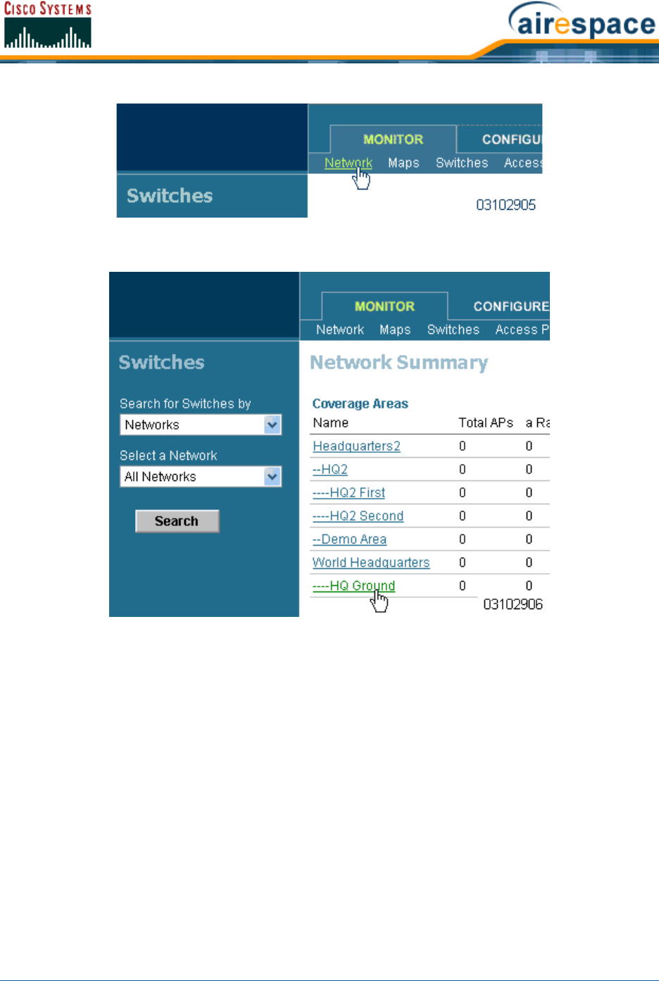
4/1/05 Adding APs to Floor Plan and Open Area Maps
OL-7426-02
•In the Network Summary page, left-click the desired Floor Plan or Outdoor Area map.
Cisco WCS displays the associated Coverage Area Map similar to the following:
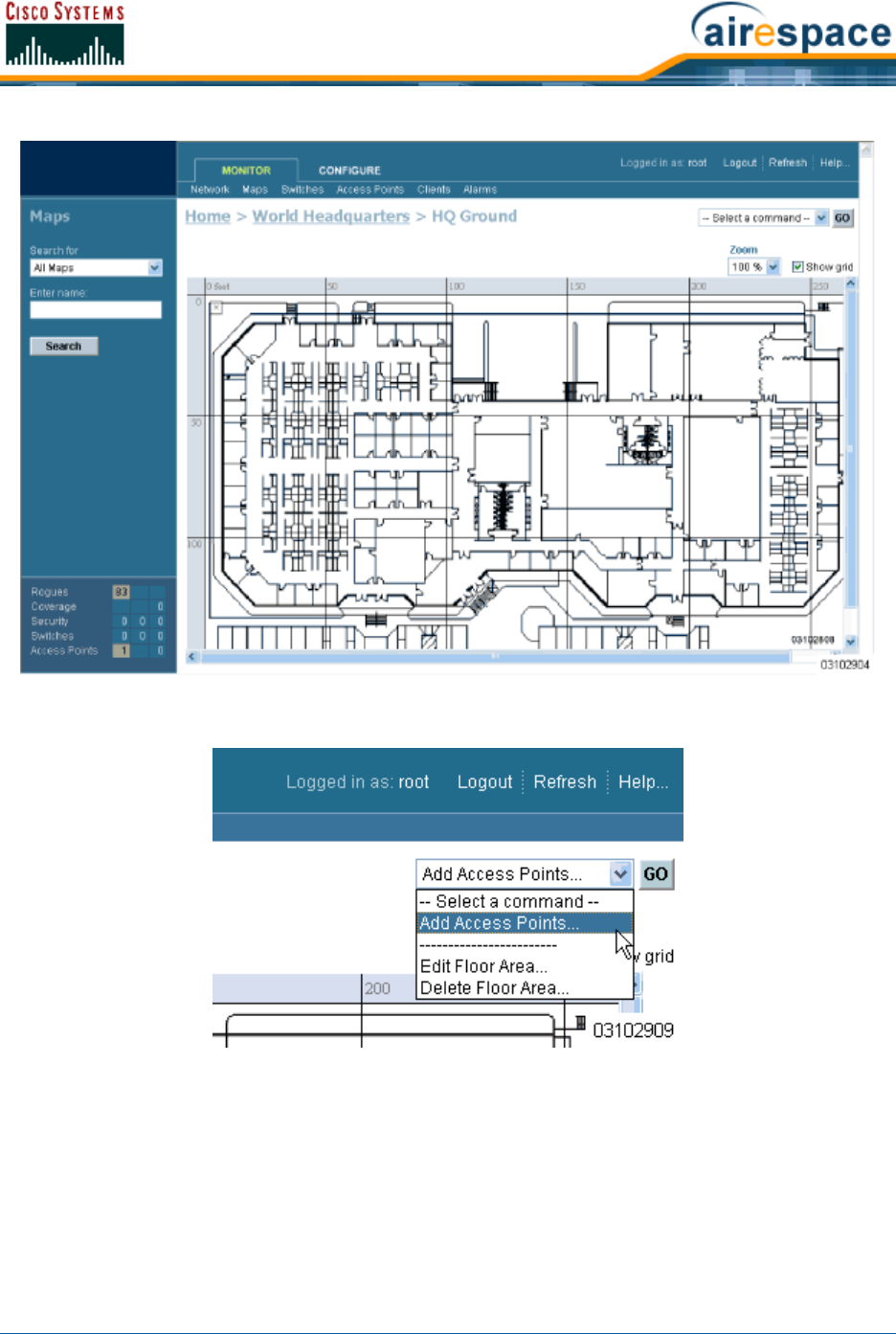
4/1/05 Adding APs to Floor Plan and Open Area Maps
OL-7426-02
•In the Button Area, select Add Access Points.
•Click GO to have the Cisco WCS User Interface display the Add Access Points page.
•In the Add Access Points page, check the Cisco 1000 Series lightweight access points to add
to the map.
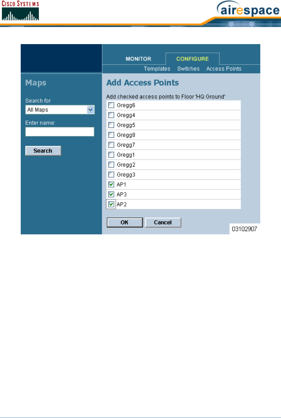
4/1/05 Adding APs to Floor Plan and Open Area Maps
OL-7426-02
•Click OK to have the Cisco WCS User Interface add the Cisco 1000 Series lightweight access
points to the map and display the Position Access Points map similar to the following:
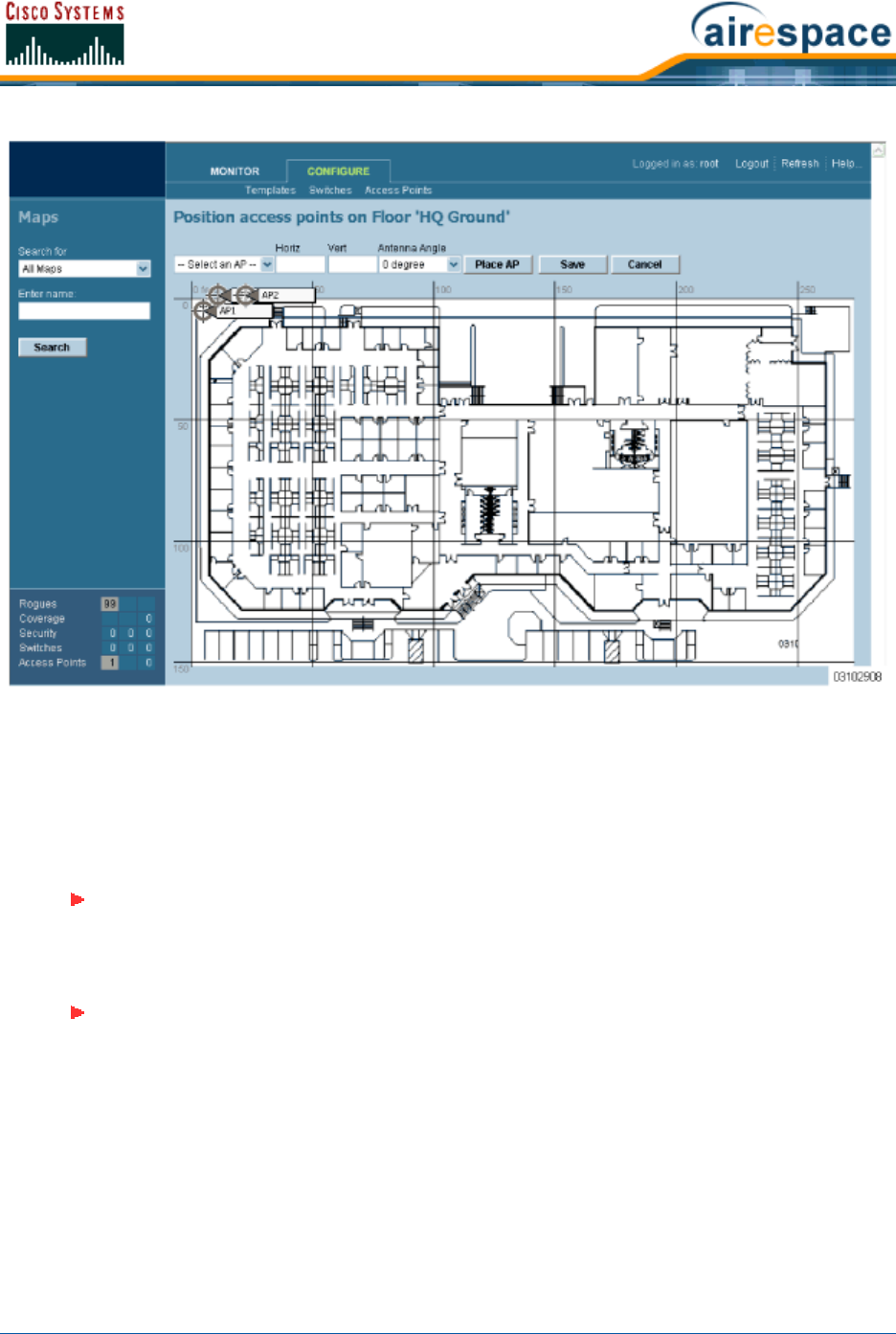
4/1/05 Adding APs to Floor Plan and Open Area Maps
OL-7426-02
Note that the Cisco 1000 Series lightweight access point icons appear in the upper left area of
the map.
•Left-click and drag the Cisco 1000 Series lightweight access point icons to indicate their
physical locations.
•Highlight each Cisco 1000 Series lightweight access point icon in turn, and select the Antenna
Angle.
•If you have imported a .PNG, .JPG, or .GIF format Coverage Area map, click Save to store the
Cisco 1000 Series lightweight access point locations and orientations, and have Cisco WCS
compute the first-order RF prediction (or “Heat Map”) for the Coverage Area.
Note: The Antenna Angle is relative to the Map “X” axis. Because the origin of the
“X” and “Y” axes is at the upper left hand corner of the Map, 0 degrees points Side A
of the Cisco 1000 Series lightweight access point to the right, 90 degrees points
Side A down, 180 degrees points Side A to the left, and so on.
Note: In the following example, AP1 and AP3 are set to 90 degrees, and AP2 is set to
0 degrees, so the three Cisco 1000 Series lightweight access points provide
maximum coverage for the inside of the building and not the loading dock.
Also note that the first display is only an approximation of the actual RF signal inten-
sity, because it does not take into account the attenuation of various building
materials, such as drywall or metal objects, nor does it display the effects of RF
signals bouncing off obstructions.
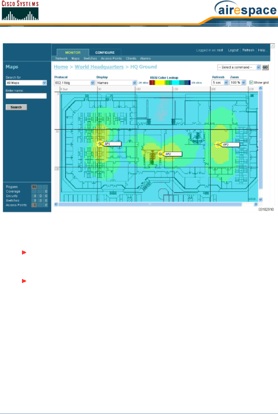
4/1/05 Adding APs to Floor Plan and Open Area Maps
OL-7426-02
•If you have imported a .FPE and a .PNG, .JPG, or .GIF format Coverage Area map, click Save to
store the Cisco 1000 Series lightweight access point locations and orientations, and have Cisco
WCS compute the second-order RF prediction (or “Heat Map”) for the Coverage Area.
Note: In the following example, AP1 is set to 0 degrees, and AP2 and AP3 are set to
90 degrees, so the three Cisco 1000 Series lightweight access points provide
maximum coverage for the right wing of the building.
Note: Also note that in the following example, each Cisco 1000 Series lightweight
access point covers a much smaller area, because of the wall attenuation factored in
by the RF Prediction algorithm.

4/1/05 Monitoring Predicted Coverage (RSSI)
OL-7426-02
•Repeat this section to assign Cisco 1000 Series lightweight access points to the remaining floor
plan maps.
You have added Cisco 1000 Series lightweight access points to floor plan maps. Continue with Using the
Cisco Wireless Control System.
Monitoring Predicted Coverage (RSSI)Monitoring Predicted Coverage (RSSI)
Use MONITOR/Maps, click an item in the Name column, left-click the floor map, from the Protocol
pulldown menu, select a protocol to access this page.
This page assumes that you have already added active APs to the selected map.
The display of predicted RF coverage on the map is determined by the selection you make from the
Protocol pulldown:
•For 802.11a and 802.11b/g: This information is displayed in the panel next to the Cisco 1000
Series lightweight access point icon as follows: n% Failed (a+b), where n is the percentage of
Cisco Radios that failed.
•For 802.11a: A colored overlay appears on the map displaying the coverage patterns for the
802.11a Cisco Radios. A Received Signal Strength Indicator (RSSI) Color Lookup appears at the
top of the map indicating the meaning of the colors. The colors show the signal strength form
RED (-35 dBm) through DARK BLUE (-85 dBm). Next to each Cisco 1000 Series lightweight
access point is a percentage of failure.
Note: These two displays are popularly known as a “heat maps”, because they shows
the relative intensity of the RF signals on the Coverage Area map.
Note: Ensure you have the correct Cisco 1000 Series lightweight access point in each
location on the map with the correct antenna angle. This will become critical later on
when you are Finding Coverage Holes and Detecting and Locating Rogue Access
Points.
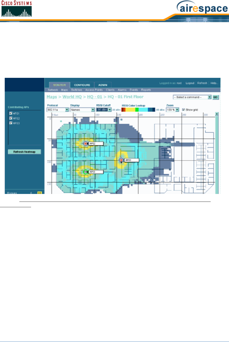
4/1/05 Monitoring Channels on a Floor Map
OL-7426-02
•For 802.11b/g: A colored overlay appears on the map displaying the coverage patterns for the
802.11b/g Cisco Radios. Received Signal Strength Indicator (RSSI) Color Lookup appears at the
top of the map indicating the meaning of the colors. The colors show the signal strength form
RED (-35 dBm) through DARK BLUE (-85 dBm). Next to each Cisco 1000 Series lightweight
access point is a percentage of failure.
A sample RF Prediction Heat Map with Cisco 1000 Series lightweight access points providing coverage
at one end of a building appears in the following figure:
Refer to Adding Cisco 1000 Series Lightweight Access Points to a Cisco Wireless LAN Controller in the
Product Guide.
Monitoring Channels on Floor MapMonitoring Channels on a Floor Map
Use MONITOR/Maps, click an item in the Name column, double-click the floor map, from the Display
pulldown menu, select Channel to access this page.
When you select this option, the channel number being used by the Cisco Radio is displayed on the
panel next to each Cisco 1000 Series lightweight access point. This display depends upon the selection
made from the Protocol pulldown as follows:
•802.11a: The display shows the channel in the following format: Ch#n, where n is the channel
number.
•802.11b/g: The display shows the channel in the following format: Ch#n, where n is the
channel number.
•802.11a and 802.11b/g: The display shows the channels in the following format: Ch#n/x,
where n represents the channel being used by the 802.11a Cisco Radio and x represents the
channel being used by the 802.11b/g Cisco Radio.
Monitoring Transmit Power Levels on a Floor MapMonitoring Transmit Power Levels on a Floor Map
Use MONITOR/Maps, click an item in the Name column, double-click the floor map, from the Display
pulldown menu, select Tx Power Level to access this page.

4/1/05 Monitoring Coverage Holes on a Floor Map
OL-7426-02
When you select this option, the power level number being used by the Cisco Radio is displayed on the
panel next to each Cisco 1000 Series lightweight access point.
Power Level (1, highest through 5, lowest) Cisco 1000 Series lightweight access point transmit power
level are as follows:
•1 = Maximum power allowed per Country Code setting
•2 = 50% power
•3 = 25% power
•4 = 6.25 to 12.5% power
•5 = 0.195 to 6.25% power
The power levels and available channels are defined by the Country Code setting and are regulated on
a country by country basis. Refer to Cisco SWAN Supported Country Codes in the Product Guide for the
maximum Transmit Power Levels for each country.
Monitoring Coverage Holes on a Floor MapMonitoring Coverage Holes on a Floor Map
Use MONITOR/Maps, click an item in the Name column, left-click the floor map, from the Display
pulldown menu, select Coverage Holes to access this page.
In the Alarm Monitor, click on a colored Coverage alarm to access this page.
Coverage holes are areas where clients cannot receive a signal from the wireless network. When
deploying wireless networks, there is a trade-off between the cost of the initial network deployment
and the percentage of coverage hole areas. A reasonable coverage hole criterion for launch is between
2 and 10 percent. This means that between two and ten test locations out of 100 random test locations
may receive marginal service. After launch, the Cisco SWAN Radio Resource Management (RRM) identi-
fies these coverage areas and reports them to the IT manager, allowing the IT manager to fill holes
based on user demand. This percentage is shown in the panel next to each Cisco 1000 Series light-
weight access point on the map. They are displayed as follows:
•802.11a: The display shows the coverage hole percentage for this Cisco Radio.
•802.11b/g: The display shows the coverage hole percentage for this Cisco Radio.
•802.11a and 802.11b/g: The display shows the total coverage hole percentage for both Cisco
Radios.
Monitoring Users on a Floor MapMonitoring Users on a Floor Map
Use MONITOR/Maps, click an item in the Name column, single-click the floor map, from the Display
pulldown menu, select Users to access this page.
When you select this option, the number of clients being used by the Cisco Radio is displayed on the
panel next to each Cisco 1000 Series lightweight access point. This display depends upon the selection
made from the Protocol pulldown as follows:
•802.11a: The display shows the number of clients using this protocol in the form n clients,
where n is the number of clients. Click “n clients” to display a list of clients. Refer to Monitoring
Clients From a Floor Map.
•802.11b/g: The display shows the number of clients using this protocol. Click “n clients” to
display a list of clients. Refer to Monitoring Clients From a Floor Map.
•802.11a and 802.11b/g: The display shows the total number of clients using a combination of
both protocols. Click “n clients” to display a list of clients. Refer to Monitoring Clients From a
Floor Map.

4/1/05 Monitoring Clients From a Floor Map
OL-7426-02
Monitoring Clients From a Floor MapMonitoring Clients From a Floor Map
Use MONITOR/Maps, click an item in the Name column, double-click the floor map, from the Display
pulldown menu, select Users, click n clients to access this page.
This page displays client parameters.
Table - Clients
Parameter Description
Checkbox Click to select, so that a command can be applied.
User Name Name of the user. Refer to Monitor Client <client name> in the Cisco WCS
User Interface Online Help.
IP Address IP Address of the client.
MAC Address MAC address of the client.
Access Point Access Point Name. Refer to Monitor Access Points > <name> in the Cisco
WCS User Interface Online Help.
Controller IP Address of Cisco Wireless LAN Controller to which this Cisco 1000
Series lightweight access point is attached. Refer to Monitor Controllers
<IPaddr> > Summary in the Cisco WCS User Interface Online Help.
Port Port number of the Cisco Wireless LAN Controller to which this Cisco 1000
Series lightweight access point is attached.
Status Associated or non-associated.
SSID Service Set Identifier being broadcast by the Cisco Radio.
Auth Authentication enabled. Yes or No.
Protocol 802.11a or 802.11b/g.
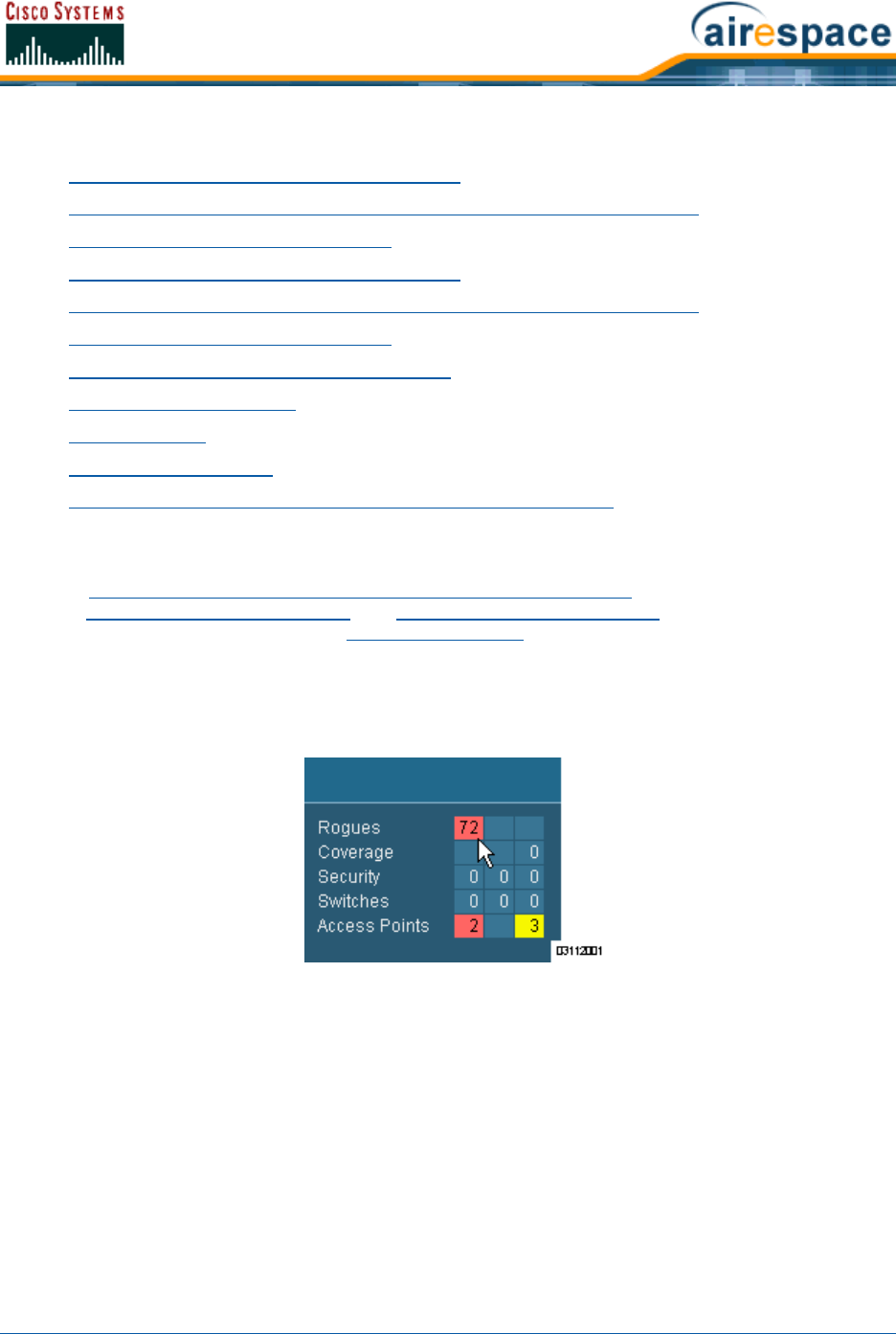
4/1/05 Troubleshooting with Cisco WCS
OL-7426-02
Troubleshooting with Cisco WCSTroubleshooting with Cisco WCS
•Checking the Cisco SWAN Network Summary
•Viewing Current Cisco Wireless LAN Controller Status and Configurations
•Viewing Cisco WCS Statistics Reports
•Checking the Cisco SWAN Network Summary
•Viewing Current Cisco Wireless LAN Controller Status and Configurations
•Viewing Cisco WCS Statistics Reports
•Detecting and Locating Rogue Access Points
•Acknowledging Rogue APs
•Locating Clients
•Finding Coverage Holes
•Pinging a Network Device from a Cisco Wireless LAN Controller
Detecting and Locating Rogue Access PointsDetecting and Locating Rogue Access Points
When the Cisco 1000 Series IEEE 802.11a/b/g Lightweight Access Points are powered up and associ-
ated with Cisco Wireless LAN Controllers, the Cisco Wireless Control System built into the Operating
System immediately starts listening for Rogue Access Points. When the Cisco Wireless LAN Controller
detects a Rogue AP, it immediately notifies Cisco WCS, which creates a rogue AP alarm.
When Cisco WCS receives a rogue AP message from a Cisco Wireless LAN Controller, Cisco WCS
generates an alarm, with an indicator visible in the lower left corner of all Cisco WCS User Interface
pages. Notice that the following example shows 72 Cisco WCS Rogue AP alarms.
•To see more detail on the Rogue APs, click the Rogues indicator to display the Rogue AP
Alarms page.
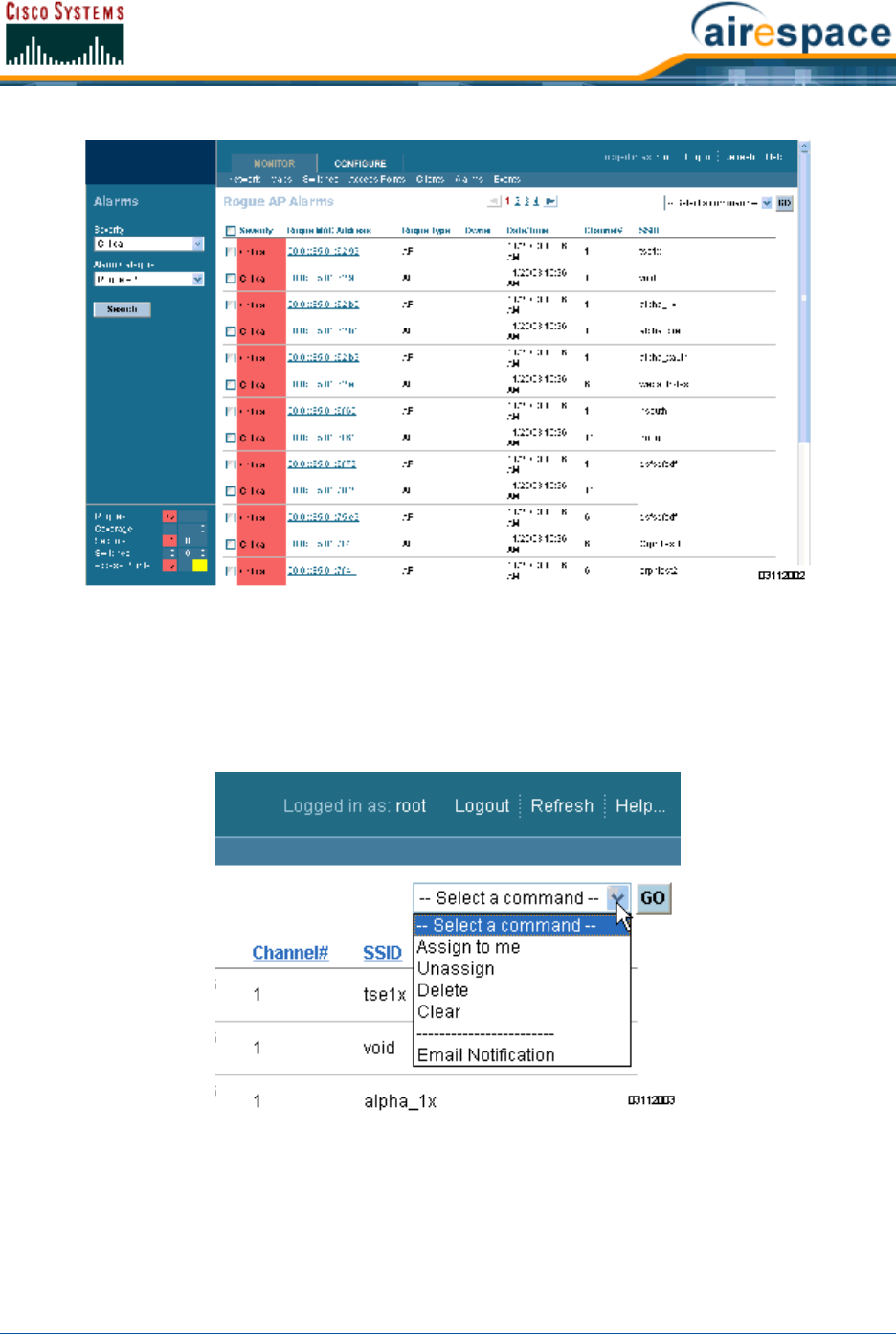
4/1/05 Detecting and Locating Rogue Access Points
OL-7426-02
In the Rogue AP Alarms page, you can see the severity of the alarms, the Rogue AP MAC
addresses, the Rogue AP types, the owners (Cisco WCS operators), the date and time when the
rogue APs were first detected, the channel numbers they are broadcasting on, and their SSIDs.
Also in this page, you can highlight one or more entries by checking the desired checkboxes,
and then allows you to apply the following commands to all selected Rogue AP alarms: Assign
to me, Unassign, Delete, Clear, or configure Email Notification.
•To see more Rogue AP information, click any Rogue MAC Address link to have Cisco WCS
display the associated Alarms > Rogue AP <MAC address> page.
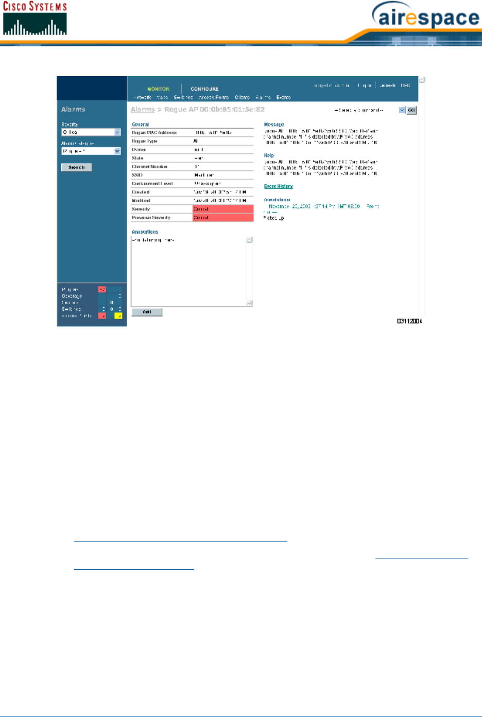
4/1/05 Detecting and Locating Rogue Access Points
OL-7426-02
The Alarms > Rogue AP <MAC address> page shows detailed information about the
rogue AP alarm, and allows you to modify the Rogue AP alarm with the following commands:
-Assign to me.
-Unassign.
-Delete.
-Show the Event History.
-Display the Detecting APs (with Radio Band, Location, SSID, Channel Number, WEP
state, short or long preamble, RSSI and SNR).
-Show a high-resolution Map with the current calculated location, or a low-resolution
Map with the Rogue AP located at the Cisco 1000 Series lightweight access point that
detects strongest RSSI transmissions.
-Show a Trend of recent RSSI signal strength.
-Set the State to Unknown, Known-Internal, or Known-External (as described in
Rogue AP Location, Tagging and Containment).
-Set up Level 1 through Level 4 Containment (as described in Rogue AP Location,
Tagging and Containment).
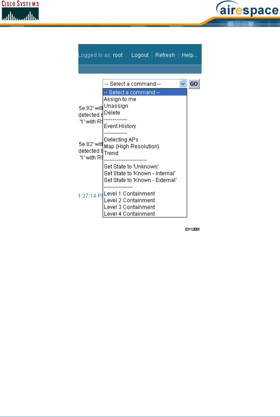
4/1/05 Detecting and Locating Rogue Access Points
OL-7426-02
•In the Alarms > Rogue AP <MAC address> page, select Map to have Cisco WCS display the
current calculated rogue AP location on the Maps > <building name> > <floor name>
page.
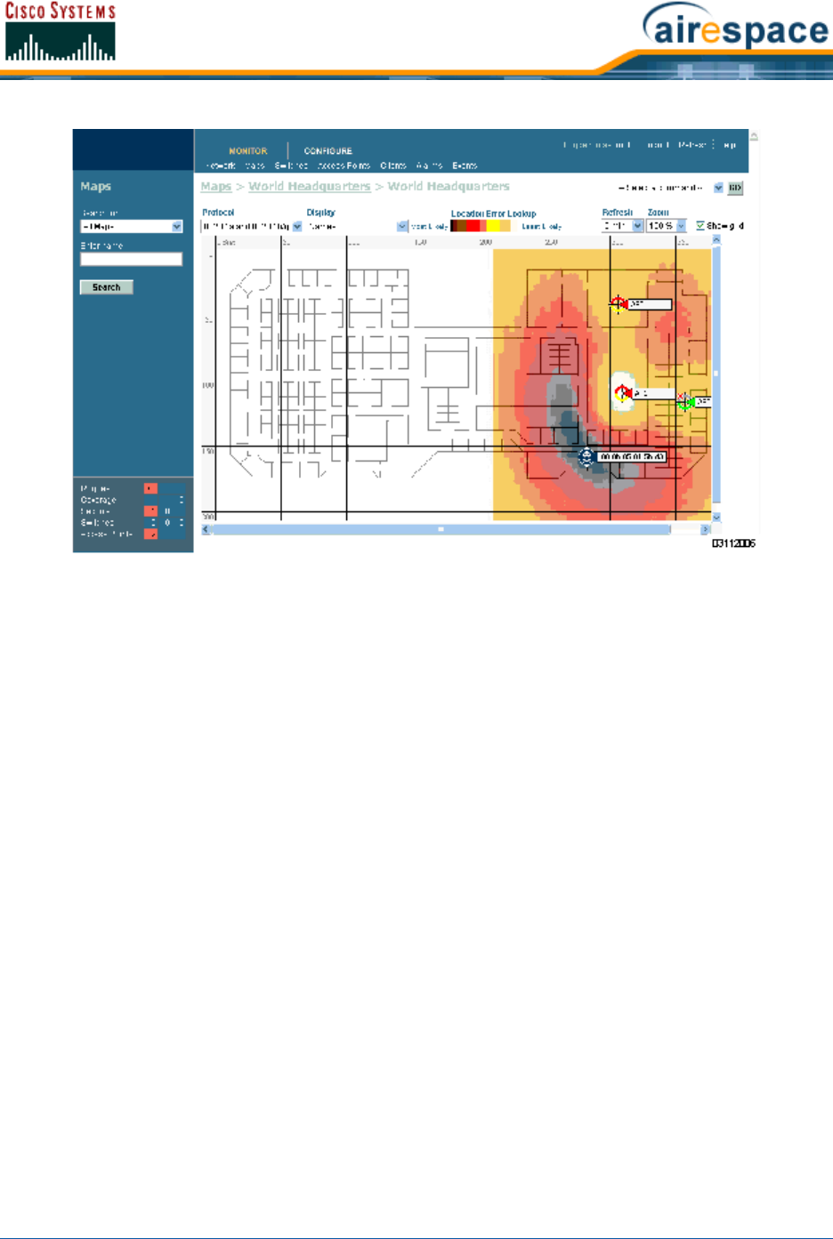
4/1/05 Acknowledging Rogue APs
OL-7426-02
Note that Cisco WCS Location (AIR-WCS-WL-1.0-K9 and AIR-WCS-LL-1.0-K9) compares RSSI
signal strength from two or more Cisco 1000 Series lightweight access points to find the most
probable location of the rogue AP, and places a small “skull-and-crossbones” indicator at its
most likely location.
Note that Cisco WCS Base (AIR-WCS-LB-1.0-K9 and AIR-WCS-LL-1.0-K9) function compares
RSSI signal strength from the rogue AP, and places a small “skull-and-crossbones” indicator
next to the Cisco 1000 Series lightweight access point receiving the strongest RSSI signal from
the Rogue AP.
Acknowledging Rogue APsAcknowledging Rogue APs
•To acknowledge known Rogue APs, navigate to the Rogue AP Alarms page. Right-click the
Rogue AP (red, unknown) to be acknowledged, and select Set State to ‘Known Internal’ or
Set State to ‘Known External’. In either case, the red Rogue AP entry is removed from the
Alarms Page.
Locating ClientsLocating Clients
Cisco WCS allows Network operators to locate clients in the enterprise. Do the following:
•Use Monitor/Clients to navigate to the Clients Summary page.
•On the Clients Summary page, in the left sidebar Search for All Clients to have Cisco WCS
display the Clients page.
•From the Clients page, click the User Name of the client you want to locate. Cisco WCS
displays the corresponding Clients <client name> page.
•From the Clients <client name> page, you have two choices for locating the client:
-In the pulldown menu, select Recent Map (high/low resolution) to locate the client
without dissociating it.
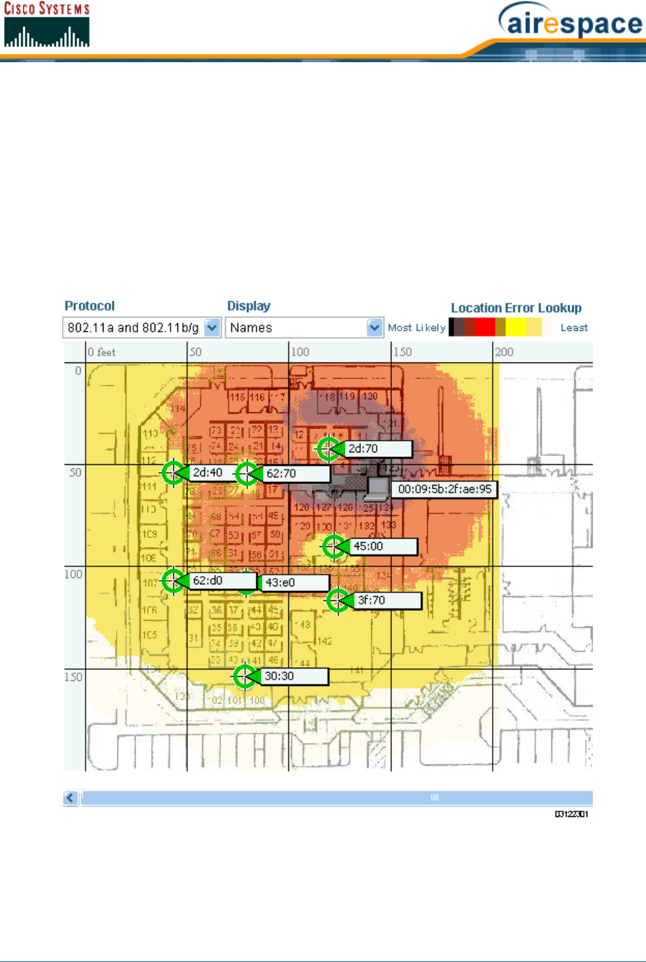
4/1/05 Finding Coverage Holes
OL-7426-02
-In the pulldown menu, select Present Map (high/low resolution) to dissociate and
then locate the client after reassociation. If you make this choice, Cisco WCS displays a
warning message and asks you to confirm that you want to continue.
Note that Cisco WCS Location (AIR-WCS-WL-1.0-K9 and AIR-WCS-LL-1.0-K9) compares RSSI
signal strength from two or more Cisco 1000 Series lightweight access points to find the most
probable location of the client, and places a small “Laptop” icon at its most likely location.
Note that Cisco WCS Base (AIR-WCS-LB-1.0-K9 and AIR-WCS-LL-1.0-K9) compares RSSI
signal strength from the client, and places a small “Laptop” icon next to the Cisco 1000 Series
lightweight access point receiving the strongest RSSI signal from the client.
Refer to the following illustration for a Heat Map showing client location.
Finding Coverage HolesFinding Coverage Holes
Coverage holes are areas where clients cannot receive a signal from the wireless network. The
Operating System Radio Resource Management (RRM) identifies these coverage hole areas and reports
them to Cisco WCS, allowing the IT manager to fill holes based on user demand.

4/1/05 Pinging a Network Device from a Cisco Wireless LAN Controller
OL-7426-02
When Cisco WCS displays the Top 5 Coverage Holes, click the Coverage indicator on the bottom left of
the Cisco WCS User Interface page (or click MONITOR/Alarms and then search for Alarm Category
Coverage) to have Cisco WCS display the Coverage Hole Alarms page. On the Coverage Hole
Alarms page, click MONITOR/Maps and then search for Access Points by Cisco 1000 Series light-
weight access point Name (this search tool is case-sensitive). Cisco WCS displays the Maps >
Search Results page, which lists the Floor or Outdoor Area where the Cisco 1000 Series lightweight
access point is located. Click the link to display the related Maps > <building name> > <floor
name> page.
On the Maps > <building name> > <floor name> page, look for areas of low signal strength near
the Cisco 1000 Series lightweight access point that reported the coverage hole. Those are the most
likely locations of coverage holes. If there do not appear to be any areas of weak signal strength, be
sure that the floor plan map is accurate, and that you have not left out any metal obstructions, such as
walls, elevator shafts, stairwells, or bookcases. If so, add them to the .FPE floor plan file and replace
the old floor plan with the new floor plan.
Pinging a Network Device from a Cisco Wireless LAN ControllerPinging a Network Device from a Cisco Wireless LAN Controller
To ping other devices from a Cisco Wireless LAN Controller:
•Use CONFIGURE/Controllers and click an IP address under the IP Address column to have
Cisco WCS display the <IPaddress> > Controller Properties page.
•On the <IPaddress> > Controller Properties page, in the left sidebar select System/
Commands to have Cisco WCS display the <IPaddress> > Controller Commands page.
•On the <IPaddress> > Controller Commands page, select Administrative Commands/
Ping from Switch and click GO.
•In the Enter an IP Address (x.x.x.x) to Ping window, enter the IP address of the network
device that the Cisco Wireless LAN Controller is to ping, and click OK.
•Cisco WCS displays the Ping Results window showing the packets sent and received. Click
Restart to ping the network device again, or click Close to stop pinging the network device
and close the Ping Results window.
Viewing Current Cisco Wireless LAN Controller Status and ConfigurationsViewing Current Cisco Wireless LAN Controller
Status and Configurations
Once you have added Cisco Wireless LAN Controllers and Cisco 1000 Series IEEE 802.11a/b/g Light-
weight Access Points to the Cisco WCS database as described in Using Cisco WCS, you can view the
Cisco SWAN status as follows:
•In the Cisco WCS User Interface, click MONITOR/Network to display the Monitor Network
Summary. Refer to the following figure and the Monitor Network Summary for more
information.
Viewing Cisco WCS Statistics ReportsViewing Cisco WCS Statistics Reports
Cisco WCS periodically collects statistics, such as RSSI, SNR, profile failures, client counts, rogue AP
trend, and busy clients, and organizes them into reports. To view these reports, use the MONITOR/
Reports screens.
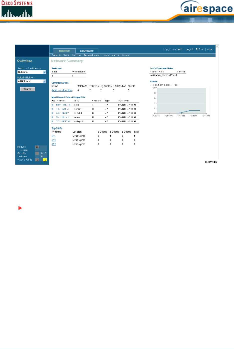
4/1/05 Updating OS Software from Cisco WCS
OL-7426-02
Figure - Typical Network Summary Page
Updating OS Software from Cisco WCSUpdating OS Software from Cisco WCS
When you plan to update the Cisco Wireless LAN Controller (and Cisco 1000 Series lightweight access
point) Operating System software from Cisco WCS, complete the following.
•Use the ping <IP Address> command in a Command Prompt window to ensure that Cisco
WCS Server can contact the Cisco Wireless LAN Controller.
-When you are downloading through the Cisco 4100 Series Wireless LAN Controller
Service port, the TFTP server MUST be on the same subnet as the Service port, because
the Service port is not routable.
-When you are downloading through the Cisco Wireless LAN Controller DS (Distribution
System) network port, the TFTP server can be on the same or a different subnet,
because the DS port is routable.
•When you are planning to use an external TFTP server, use the ping <IP Address> command
in a Command Prompt window to ensure that the Cisco WCS Server can contact the TFTP
server.
•Use Cisco WCS Configure/Switches to navigate to the All Switches page.
•In the All Switches page, select the desired Cisco Wireless LAN Controller checkbox, select the
Command Download Software, and click GO to have Cisco WCS display the Download
Software to Switch page.
Note: On the Cisco 2000 Series Wireless LAN Controller, the Cisco WCS Server MUST
be on the same subnet as the Cisco 2000 Series Wireless LAN Controller Manage-
ment Interface because this Cisco Wireless LAN Controller does not have a service
port.
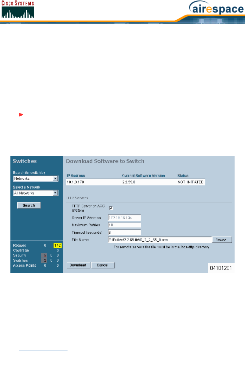
4/1/05 Managing Cisco WCS and Database
OL-7426-02
•When you are using the built-in Cisco WCS TFTP server, in the Download Software to Switch
page, be sure that TFTP Server on Cisco WCS System checkbox is selected.
-- OR --
When you are using an external TFTP server, in the Download Software to Switch page, be
sure that TFTP Server on Cisco WCS System is deselected. Then add the external TFTP
server IP address.
•In the Download Software to Switch page, click the Browse button and navigate to the OS
code update file named AS_2000_<release_number>.aes for Cisco 2000 Series Wireless LAN
Controllers or AS_4100_<release_number>.aes for Cisco 4100 Series Wireless LAN Controllers.
(For example, AS_4100_2_2_60_0.aes.) The path and filename of the OS code appear in the
File Name box.
•Click the Download button.
Cisco WCS downloads the OS code file to the Cisco WCS Server /aes-tftp directory, then down-
loads the OS code to the Cisco Wireless LAN Controller, and then the Cisco Wireless LAN
Controller writes the code to flash RAM. As Cisco WCS performs these functions, it displays its
progress in the Status box.
Refer to the Transferring Files To and From a Cisco Wireless LAN Controller section for other file upload
and download instructions.
Managing Cisco WCS and DatabaseManaging Cisco WCS and Database
•Installing Cisco WCS
Note: BE SURE you have the correct OS code file:
• Cisco 2000 Series Wireless LAN Controller OS code files are named
AS_2000_<release_number>.aes.
• Cisco 4100 Series Wireless LAN Controller OS code files are named
AS_4100_<release_number>.aes.

4/1/05 Installing Cisco WCS
OL-7426-02
•Updating Windows Cisco WCS
•Updating Linux Cisco WCS
•Reinitializing the Windows Cisco WCS Database
•Reinitializing the Linux Cisco WCS Database
•Administering Cisco WCS Users and Passwords
Installing Cisco WCSInstalling Cisco WCS
Refer to the Windows Cisco WCS Quick Start Guide or Linux Cisco WCS Quick Start Guide the for
instructions on how to install Cisco WCS on a Cisco WCS Server.
Updating Windows Cisco WCSUpdating Windows Cisco WCS
Do the following:
•If possible, stop all Cisco WCS User Interfaces (Stopping a Cisco WCS User Interface) to
stabilize the database.
•Stop Cisco WCS (Stopping the Cisco WCS Windows Application or Stopping the Cisco WCS
Windows Service).
•Manually create a backup directory with no spaces in the name, such as C:\WCS22_Backup\.
•From the Windows START button, select the Programs menu, and then select Cisco Wireless
Control System 2.2/Backup.
The backup script opens the Backup DOS window and the Select Backup directory window.
•In the Select Backup directory window, highlight the backup directory you created above and
click OK.
The backup database script creates subdirectories in the C:\WCS22_Backup\ directory, and
backs up the Cisco WCS database and the floor plan, building, and area maps to the
C:\WCS22_Backup\conf and C:\WCS22_Backup\mapimages directories.
Note: Be sure the directory name does not include any spaces, or the backup script
will generate error messages.
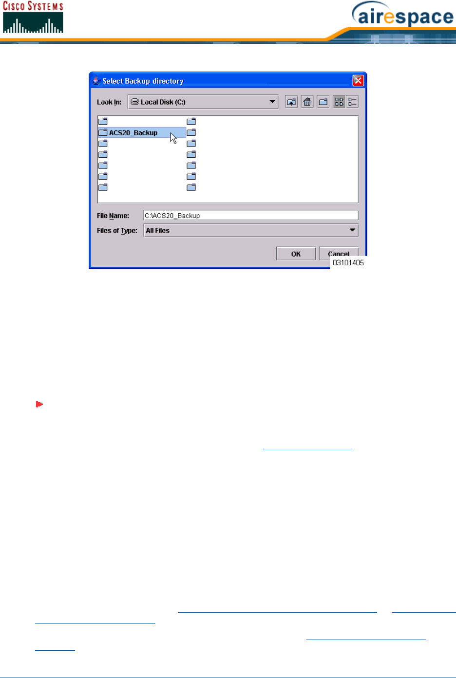
4/1/05 Updating Windows Cisco WCS
OL-7426-02
•When the Backup Status window opens and displays the Backup Succeeded. You may restart
the Cisco WCS Server now. message, click OK.
•Uninstall the Cisco Wireless Control System application using the Control Panel/Add or
Remove Programs application.
•When the JExpress Uninstaller window displays Program uninstalled message, click Finished
to close the JExpress Uninstaller window.
•If any part of the C:\Program Files\WCS22 folder remains on the hard drive, manually
delete the folder and all contents.
•Reinstall the Cisco WCS application as described in Installing Cisco WCS.
•From the Windows START button, select the Programs menu, and then select Cisco Wireless
Control System 2.2/Restore.
•In the Select Backup directory window, highlight the backup directory you created above and
click OK.
•The restore database script restores the Cisco WCS database and the floor plan, building, and
area maps to the new Cisco WCS installation.
•When the Restore Status page opens and displays the Restore Succeeded. You may restart
the Cisco WCS Server now. message, click OK.
If you receive an error message, scroll down the page to find the error. Normally, the only error
that will halt a backup is if an incorrect directory is specified; if this is the case, repeat this
procedure with the correct directory to complete the backup.
•Start Cisco WCS as described in Starting Cisco WCS as a Windows Application or Starting Cisco
WCS as a Windows Service.
•Start one or more Cisco WCS User Interfaces as described in Starting a Cisco WCS User
Interface.
Note: If you fail to delete the previous Cisco WCS installation, you will receive the
following error message upon reinstall: Cisco WCS already installed. Please
uninstall the older version before installing this version.

4/1/05 Updating Linux Cisco WCS
OL-7426-02
Updating Linux Cisco WCSUpdating Linux Cisco WCS
Do the following:
•If possible, stop all Cisco WCS User Interfaces (Stopping a Cisco WCS User Interface) to
stabilize the database.
Create a Backup Directory
•If not already done, log in as root.
•Using the Linux command line interface, navigate to the default /usr/local/ directory (or any
other directory).
•Create a backup directory for the Cisco WCS database with no spaces in the name; for instance,
mkdir WCS22BAK.
Stop the Cisco WCS Server Application
•Navigate to the default /usr/local/bin/WCS22 directory (or the directory chosen during
installation).
•Enter ./StopACSServer to stop Cisco WCS.
Back Up the Cisco WCS Server Database
•Enter ./Backup to start the Cisco WCS database backup. The Backup script displays the Select
Backup directory window.
•In the Select Backup directory window, navigate to the NAME of the backup directory you
created above (not IN the directory), and click OK.
•When the Backup script displays the Backup Succeeded. You may restart the Cisco WCS Server
now message, click OK.
Uninstall the Old Cisco WCS Server Application
•Enter ./uninstallAirespaceControlSystem to uninstall Cisco WCS.
•Click Yes to continue with the uninstallation.
•Click Finished when the uninstallation is completed.
Install the New Cisco WCS Server Application
•Find the cisco-wcs-location-2.2.X.Y-install.bin (High-Resolution Cisco WCS Location) or
cisco-wcs-base-2.2.X.Y-install.bin (Low-Resolution Cisco WCS Base) file, where 2.2.X.Y is the
software build. This file may be found on the Linux Cisco WCS CD-ROM or may be obtained
from Cisco Technical Assistance Center (TAC).
•In the Linux command line interface, navigate to the cisco-wcs-location-2.2.X.Y-install.bin
or cisco-wcs-base-2.2.X.Y-install.bin file directory.
•Enter ./cisco-wcs-location-2.2.X.Y-install.bin or ./
cisco-wcs-base-2.2.X.Y-install.bin to start the install script.
The install script prepares the install environment, and displays the Installer window, which
prompts you to change the HTTP and HTTPS ports, if necessary. Click Next when done.

4/1/05 Updating Linux Cisco WCS
OL-7426-02
•In the Installer/About to Install window, click Next.
•In the Installer window, select the default /usr/local/bin/WCS22 (or any other) directory.
Click Install.
The install script copies the Cisco WCS files to the selected directory and verifies them.
•The install script displays Checking for Port Availability. Click Next to continue. Click Next.
•The install script completes the installation and displays You may restart the Cisco WCS Server
now. Select Finished to close down the install script.
Restore the Cisco WCS Server Database
•Navigate to the default /usr/local/bin/WCS22 directory (or the directory chosen during
installation).
•Enter ./Restore to start the Cisco WCS database backup. The Backup script displays the
Select Backup directory window.
•In the Select Backup directory window, navigate to the NAME of the backup directory you
created above (not IN the directory), and click OK.
•When the Backup script displays You may restart the Cisco WCS Server now, click OK.
Start the Cisco WCS Server Application
•In the /usr/local/bin/WCS22 directory (or the directory chosen during installation).
•Enter ./StartACSServer to start Cisco WCS.
•Enter ./CheckServerStatus to open the Cisco WCS Server Status window.
•When the Start Cisco WCS Server Status window displays Cisco WCS Server is up. Please
connect your clients (Cisco WCS User Interfaces) using Http Port: 80 or Https Port: 433 (or
whichever HTTP: or HTTPS: port you selected in the Install the New Cisco WCS Server Appli-
cation step), Cisco WCS has started and is ready to host Cisco WCS User Interfaces.
Note: If you receive the /usr/local/bin/WCS22 exists. Use it anyway? message, click
No, navigate to the ./usr/local/bin/WCS22 directory and delete any remaining
subdirectories and files (rm -Rf webnms, for example), and continue with the
installation.
CAUTION: When you plan to shut down Cisco WCS, refer to Starting and Stopping
Linux Cisco WCS.

4/1/05 Reinitializing the Windows Cisco WCS Database
OL-7426-02
Reinitializing the Windows Cisco WCS DatabaseReinitializing the Windows Cisco WCS Database
You only have to reinitialize the Windows Cisco WCS database when the Cisco WCS database becomes
corrupted.
•Navigate to the \WCS22 directory.
•Navigate to the \bin subdirectory.
•In the \bin subdirectory, double-click the reinitDatabase.bat file.
The database reinitialize script displays the startdb.bat DOS window.
•Select the startdb.bat window, and press any key to continue.
The startdb.bat script displays the Reinitialize Web NMS Database window.
•In response to the Do you want to Reinitialize Web NMS? prompt in the Reinitialize Web NMS
Database window, select Yes.
The startdb.bat window displays many “accomplished” messages. When the Cisco WCS
database is reinitialized, the Reinitialize Web NMS Database window reappears.
•In response to the Successfully reinitialized the Database prompt in the Reinitialize Web
NMS Database window, select OK.
The Reinitialize Web NMS Database window closes, and the startdb.bat window displays a
Press any key to continue prompt.
•In the startdb.bat window, press any key. The startdb.bat window closes.
You have reinitialized the Cisco WCS database. Continue with Using the Cisco Wireless Control System.
Reinitializing the Linux Cisco WCS DatabaseReinitializing the Linux Cisco WCS Database
You only have to reinitialize the Linux Cisco WCS database when the Cisco WCS database becomes
corrupted.
•If not already done, log in as root.
•Using the Linux command line interface, navigate to the default /usr/local/WCS22/bin
directory (or the directory chosen during installation).
•Enter ./reinitDatabase.sh to reinitialize the Cisco WCS database.
You have reinitialized the Cisco WCS database. Continue with Using the Cisco Wireless Control System.
Administering Cisco WCS Users and PasswordsAdministering Cisco WCS Users and Passwords
Cisco WCS supports four User Groups:
•To monitor Cisco WCS operations, users must be part of the System Monitoring Group.
•To monitor and configure Cisco WCS operations, users must be part of the ConfigManagers
Group.
•To monitor and configure Cisco WCS operations, and perform all system administration tasks
except administering Cisco WCS users and passwords, users must be part of the Admin Group.
CAUTION: If you reinitialize the Cisco WCS database after you have been working in
the Cisco WCS application, you will delete all your saved Cisco WCS data!
CAUTION: If you reinitialize the Cisco WCS database after you have been working in
the Cisco WCS application, you will delete all your saved Cisco WCS data!

4/1/05 Reinitializing the Linux Cisco WCS Database
OL-7426-02
•To monitor and configure Cisco WCS operations, and perform all system administration tasks
including administering Cisco WCS users and passwords, users must be part of the
SuperUsers Group.
This section describes how to add user accounts and assign them to a User Group, change passwords,
and delete user accounts using the Cisco WCS Administration function.
Adding User AccountsAdding User Accounts
•If not already done, start Cisco WCS as described in the Starting Cisco WCS as a Windows
Application or Starting Cisco WCS as a Windows Service.
•Select User Admin/Security Administration to display the Security Administration page.
•In the Security Administration page, click the Add User (single person) icon to display the
User Administration page.
•In the User Administration page, add the new username and password. Click Next to display
the User account expiry and Password expiry parameters.
•In this page, accept or change the desired expiration times for the user account and password.
Click Next to display the Group based permissions, Direct Assignment, and Assign
groups for the user parameters.
•As you are going to assign the new user account to a group which already has permissions
assigned, be sure the Group based permissions and Direct Assignment boxes are checked.
•In the Assign groups for the user section, assign the new user account to one of the four
User Group names: System Monitoring, ConfigManagers, Admin, or SuperUsers.
•Ignore the rest of the fields in this page, and click Finish to complete adding the new user
account.
•Close the Security Administration page.
•Close the Cisco Wireless Control System Release 2.2 page.
The new User Account has been added and can be used immediately. If necessary, refer to the Deleting
User Accounts section to delete the default user accounts provided with the Cisco Wireless Control
System.
Changing PasswordsChanging Passwords
•If not already done, start Cisco WCS as described in the Starting Cisco WCS as a Windows
Application or Starting Cisco WCS as a Windows Service.
•If not already done, log into Cisco WCS Administration as a user assigned to the SuperUsers
Group as described in Adding User Accounts.
•Select User Admin/Security Administration to display the Security Administration page.
•In the Security Administration page, highlight a user account, and select Edit/Change
Password to display the Change Password dialog.
•In the Change Password dialog, enter the new password and click Ok to change the password
for the selected user account.
•Close the Security Administration page.
CAUTION: As soon as you have logged into the Cisco WCS User Interface as
Super1, Cisco SWAN recommends that you create a new superuser assigned to the
Super Users Group, and then delete the Super1 user to prevent undesired access to
Cisco WCS Super User operations.

4/1/05 Reinitializing the Linux Cisco WCS Database
OL-7426-02
•Close the Cisco Wireless Control System Release 2.2 page.
The User Account has been changed and can be used immediately.
Deleting User AccountsDeleting User Accounts
•If not already done, start Cisco WCS as described in the Starting Cisco WCS as a Windows
Application or Starting Cisco WCS as a Windows Service.
•If not already done, log into Cisco WCS Administration as a user assigned to the SuperUsers
Group as described in Adding User Accounts.
•Select User Admin/Security Administration to display the Security Administration page.
•In the Security Administration page, highlight the user account to delete, and select Edit/
Delete to display the Warning! On deleting this user you would no longer be able to log
on with this user name, are you sure you want to do this? dialog.
•In the Warning! dialog, click Yes to delete the selected user account.
•Close the Security Administration page.
•Close the Cisco Wireless Control System Release 2.2 page.
The deleted User Account can no longer be used.

4/1/05 Using the Web User Interface
OL-7426-02
Using the Web User InterfaceUsing the Web User Interface
The Web User Interface is described in Web User Interface section.
Note that you can use either the Service-Port Interface (recommended) or Management Interface,
whose IP Address(es) were set using the Startup Wizard or the Configuring System Parameters section.
Also note that you can have up to 21 simultaneous Web User Interface sessions, but the automatic
refresh time for the Monitor/Summary page will be longer if there are more than 10 simultaneous
sessions.
Log into the Web User Interface by doing the following:
•Start a Web Browser on any workstation connected to the Internet (Cisco SWAN recommends
Internet Explorer 6.0 or later on a Windows workstation for full functionality).
•For an unsecure http connection, enter the Cisco Wireless LAN Controller IP Address (http://
<Cisco Wireless LAN Controller_IPaddress>/) in the Web Browser Address field and press
<RETURN>.
--OR--
•For a secure https (HTTP + SSL) connection, enter the Cisco Wireless LAN Controller IP Address
(https://<Cisco Wireless LAN Controller_IPaddress>/) in the Web Browser Address field and
press <RETURN>. (This connection was configured using the Adding SSL to the Web User
Interface procedure.)
Note: Some popup window filters can be configured to block the Web User Interface
Online Help pages. If your system cannot display the Online Help windows, disable or
reconfigure your browser popup filter software.
Note: If you receive a “The Document contains no data” error message, the corre-
sponding http Web Mode and/or https Secure Web Mode is disabled. If you receive
the error when attempting to use http AND https, use the CLI to log into the Cisco
Wireless LAN Controller as described in the Using the Cisco SWAN CLI section, or use
Cisco WCS to log into the Cisco Wireless LAN Controller as described in Using the
Cisco Wireless Control System.
Note: Each time you access the secure https (http + SSL) Cisco Wireless LAN
Controller website, you may receive the following Security Alert:
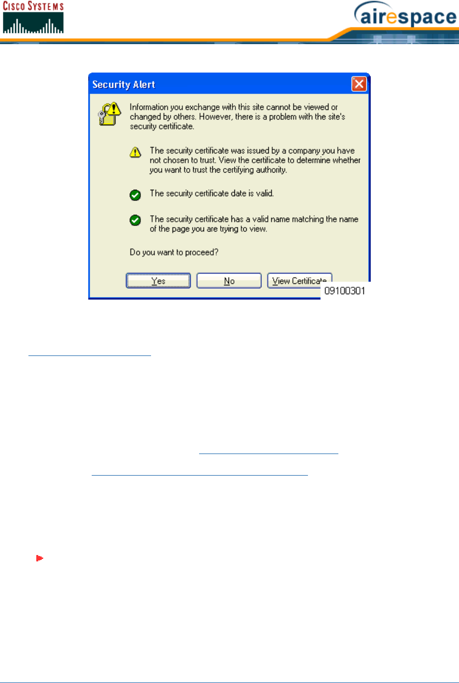
4/1/05 Adding Cisco 1000 Series Lightweight Access Points to a Cisco Wireless LAN
Controller
OL-7426-02
When you see the Security Alert, click Yes.
Once you have logged into the Web User Interface, use the context-sensitive (F1) online help (included
in the Operating System Software section) to configure and monitor the Cisco Wireless LAN Controller.
Adding Cisco 1000 Series Lightweight Access Points to a Cisco Wireless LAN
ControllerAdding Cisco 1000 Series Lightweight Access Points to a Cisco Wireless LAN Controller
You can add Cisco 1000 Series lightweight access points to an existing Cisco Wireless LAN Controller
using the Web User Interface.
•The Cisco 1000 Series lightweight access points connect to the Cisco Wireless LAN Controller
through the network as described in Cisco SWAN Wired Connections. When an Cisco 1000
Series lightweight access point powers up, it searches for a Cisco Wireless LAN Controller as
described in Cisco Wireless LAN Controller Failover Protection.
Adding CA Certificates to a Cisco Wireless LAN ControllerAdding CA Certificates to a Cisco Wireless LAN Controller
Certification Authority public-key certificates are used to authenticate the Web server and encrypt data
transmissions between Web server and browser. The CA certificates are issued by a trusted Certifica-
tion Authority, or CA.
Note: You can obtain a CA Certificate from three sources: Factory-supplied, Oper-
ator-generated, and Purchased from a trusted CA. This procedure only applies to
adding an Operator-generated or Purchased ID Certificate, as the Factory-supplied
Certificate is already stored in the Cisco Wireless LAN Controller NVRAM. You do not
need to complete this procedure if you choose to use the Factory-supplied CA
Certificate.

4/1/05 Adding ID Certificates to a Cisco Wireless LAN Controller
OL-7426-02
When you obtain certificates (usually in an email from the CA or from your key-generation program), it
is a simple matter to add the CA certificate to your Cisco Wireless LAN Controller:
•Launch a Web User Interface session as described in Using the Web User Interface.
•Navigate to the CA Certification page in the Web User Interface.
•Copy the Certificate (a large block of ASCII characters) from your email or text viewer
program, and paste it into the CA Certification box.
•Click Apply.
The CA Certificate is now in the Cisco Wireless LAN Controller Volatile RAM. Use ‘System Reboot with
Save’ to save the CA Certificate to NVRAM, so the CA Certificate is preserved across restarts.
Adding ID Certificates to a Cisco Wireless LAN ControllerAdding ID Certificates to a Cisco Wireless LAN Controller
ID Certificates and Private Keys are used by Web server operators to ensure secure server operation.
The ID certificate and key are used to authenticate the server and encrypt data transmissions between
server and browser.
When you obtain ID certificates (usually in an email from the CA or from your key-generation
program), it is a simple matter to add the ID certificate and key to your Cisco Wireless LAN Controller:
•Launch a Web User Interface session as described in Using the Web User Interface.
•Navigate to the ID Certificate > New page in the Web User Interface.
•Type or paste the ID Certificate Name into the Certificate Name box.
•Type a Private Key (Password) into the Certificate Password box.
•Copy the Certificate (a large block of ASCII characters) from your email or text viewer
program, and paste it into the ID Certification box.
•Click Apply.
The ID Certificate and Key are now in the Cisco Wireless LAN Controller Volatile RAM. Use ‘System
Reboot with Save’ to save the ID Certificate and Key to NVRAM, so the Certificate and Key are
preserved across restarts.
CAUTION: Each certificate has a variable-length embedded RSA Key. The RSA key
can be from 512 bits, which is relatively insecure, through thousands of bits, which is
very secure. When you are obtaining a new certificate from a Certificate Authority
(such as the Microsoft CA), BE SURE the RSA key embedded in the certificate is AT
LEAST 768 Bits.
Note: You can obtain an ID Certificate and Private Key from three sources:
Factory-supplied, Operator-generated, and Purchased from a trusted CA. This
procedure only applies to adding an Operator-generated or Purchased ID Certificate
and Key, as the Factory-supplied Certificate and Key are already stored in the Cisco
Wireless LAN Controller NVRAM. You do not need to complete this procedure if you
choose to use the Factory-supplied ID Certificate and Key.
CAUTION: Each certificate has a variable-length embedded RSA Key. The RSA key
can be from 512 bits, which is relatively insecure, through thousands of bits, which is
very secure. When you are obtaining a new certificate from a Certificate Authority
(such as the Microsoft CA), BE SURE the RSA key embedded in the certificate is AT
LEAST 768 Bits.

4/1/05 Troubleshooting Tips
OL-7426-02
Troubleshooting TipsTroubleshooting Tips
You can use the following sections to troubleshoot your Cisco SWAN:
•Using Error Messages
•Using Reason and Status Codes in the Trap Log
•Using Cisco 1000 Series Lightweight Access Point LEDs
Using Error MessagesUsing Error Messages
The Operating System may display any of the error messages described below.
Table - Error Messages and Descriptions
Error Message Description
STATION_DISASSOCIATE Client may have intentionally terminated usage or
may have experienced a service disruption.
STATION_DEAUTHENTICATE Client may have intentionally terminated usage or it
could indicate an authentication issue.
STATION_AUTHENTICATION_FAIL Check disable, key mismatch or other configuration
issues.
STATION_ASSOCIATE_FAIL Check load on the Cisco Radio or signal quality
issues.
LRAD_ASSOCIATED The associated Cisco 1000 Series lightweight access
point is now managed by this Cisco Wireless LAN
Controller.
LRAD_DISASSOCIATED Cisco 1000 Series lightweight access point may have
associated with a different Cisco Wireless LAN
Controller or may have become completely
unreachable.
LRAD_UP Cisco 1000 Series lightweight access point is opera-
tional, no action required.
LRAD_DOWN Cisco 1000 Series lightweight access point may have
a problem or is administratively disabled.
AIRONETAP_UP Aironet AP is responding to SNMP polls.
AIRONETAP_DOWN Aironet AP is not responding to SNMP polls, check
network connections, Cisco 1000 Series lightweight
access point and its SNMP settings.
ORINOCOAP_UP ORINOCO AP is responding to SNMP polls.
ORINOCOAP_DOWN ORINOCO AP is not responding to SNMP polls, check
network connections, ORINOCO AP and its SNMP
settings.
LRADIF_UP Cisco Radio is UP.

4/1/05 Troubleshooting Tips
OL-7426-02
LRADIF_DOWN Cisco Radio may have a problem or is administra-
tively disabled.
LRADIF_LOAD_PROFILE_FAILED Client density may have exceeded system capacity.
LRADIF_NOISE_PROFILE_FAILED The non-802.11 noise has exceed configured
threshold.
LRADIF_INTERFERENCE_PROFILE_FAILED 802.11 interference has exceeded threshold on
channel -- check channel assignments.
LRADIF_COVERAGE_PROFILE_FAILED Possible coverage hole detected - check Cisco 1000
Series lightweight access point history to see if
common problem - add Cisco 1000 Series light-
weight access points if necessary.
LRADIF_LOAD_PROFILE_PASSED Load is now within threshold limits.
LRADIF_NOISE_PROFILE_PASSED Detected noise is now less than threshold.
LRADIF_INTERFERENCE_PROFILE_PASSED Detected interference is now less than threshold.
LRADIF_COVERAGE_PROFILE_PASSED Number of clients receiving poor signal are within
threshold.
LRADIF_CURRENT_TXPOWER_CHANGED Informational message.
LRADIF_CURRENT_CHANNEL_CHANGED Informational message.
LRADIF_RTS_THRESHOLD_CHANGED Informational message.
LRADIF_ED_THRESHOLD_CHANGED Informational message.
LRADIF_FRAGMENTATION_THRESHOLD_
CHANGED Informational message.
RRM_DOT11_A_GROUPING_DONE Informational message.
RRM_DOT11_B_GROUPING_DONE Informational message.
ROGUE_AP_DETECTED May be a security issue, use maps and trends to
investigate.
ROGUE_AP_REMOVED Detected Rogue has timed out - May have shut down
or moved out of coverage area.
AP_MAX_ROGUE_COUNT_EXCEEDED The current number of active rogues has exceeded
system threshold.
LINK_UP Positive confirmation message.
LINK_DOWN Port may have a problem or is administratively
disabled.
LINK_FAILURE Port may have a problem or is administratively
disabled.
Table - Error Messages and Descriptions (Continued)
Error Message Description

4/1/05 Troubleshooting Tips
OL-7426-02
AUTHENTICATION_FAILURE Attempted security breech - please investigate.
STP_NEWROOT Informational message.
STP_TOPOLOGY_CHANGE Informational message.
IPSEC_ESP_AUTH_FAILURE Check WLAN IPSec configuration.
IPSEC_ESP_REPLAY_FAILURE Check for attempt to spoof IP Address.
IPSEC_ESP_POLICY_FAILURE Check for IPSec configuration mismatch between
WLAN and client.
IPSEC_ESP_INVALID_SPI Informational message.
IPSEC_OTHER_POLICY_FAILURE Check for IPSec configuration mismatch between
WLAN and client.
IPSEC_IKE_NEG_FAILURE Check for IPSec IKE configuration mismatch between
WLAN and client.
IPSEC_SUITE_NEG_FAILURE Check for IPSec IKE configuration mismatch between
WLAN and client.
IPSEC_INVALID_COOKIE Informational message.
RADIOS_EXCEEDED Maximum number of supported Cisco Radios
exceeded - Check for Cisco Wireless LAN Controller
failure in the same Layer 2 network or add another
Cisco Wireless LAN Controller.
SENSED_TEMPERATURE_HIGH Check fan, air conditioning and/or other cooling
arrangements.
SENSED_TEMPERATURE_LOW Check room temperature and/or other reasons for
low temperature.
TEMPERATURE_SENSOR_FAILURE Replace temperature sensor ASAP.
TEMPERATURE_SENSOR_CLEAR Temperature sensor is operational.
POE_CONTROLLER_FAILURE Check Direct-Connect APs - possible serious failure
detected.
MAX_ROGUE_COUNT_EXCEEDED The current number of active rogues has exceeded
system threshold.
SWITCH_UP Cisco Wireless LAN Controller is responding to SNMP
polls.
SWITCH_DOWN Cisco Wireless LAN Controller is not responding to
SNMP polls, check Cisco Wireless LAN Controller and
SNMP settings.
RADIUS_SERVERS_FAILED Check network connectivity between RADIUS and
the Cisco Wireless LAN Controller.
Table - Error Messages and Descriptions (Continued)
Error Message Description

4/1/05 Troubleshooting Tips
OL-7426-02
Using Client Reason and Status Codes in the Trap LogUsing Reason and Status Codes in the Trap Log
As described in Web User Interface Online Help, the Clients > Detail page lists the Reason and Status
Codes you are likely to encounter when reviewing the Trap Logs. For your convenience the Reason and
Status Codes and their descriptions are listed in the following sections:
•Client Reason Codes
•Client Status Codes
Client Reason CodesClient Reason Codes
The Client Reason code may be any of the following:
CONFIG_SAVED Running configuration has been saved to flash - will
be active after reboot.
MULTIPLE_USERS Another user with the same username has logged in.
FAN_FAILURE Monitor Cisco Wireless LAN Controller temperature to
avoid overheating.
POWER_SUPPLY_CHANGE Check for power-supply malfunction.
COLD_START Cisco Wireless LAN Controller may have been
rebooted.
WARM_START Cisco Wireless LAN Controller may have been
rebooted.
Table - Client Reason Code Descriptions and Meanings
Client
Reason
Code Description Meaning
0 noReasonCode normal operation
1 unspecifiedReason client associated but no longer authorized
2 previousAuthNotValid client associated but not authorized
3 deauthenticationLeaving the Cisco 1000 Series lightweight access point
went offline, deauthenticating the client
4 disassociationDueToInactivity client session timeout exceeded
5 disassociationAPBusy the Cisco 1000 Series lightweight access point is
busy, performing load balancing, for example
6 class2FrameFromNonAuthStation client attempted to transfer data before it was
authenticated
7class2FrameFromNonAssStation client attempted to transfer data before it was
associated
Table - Error Messages and Descriptions (Continued)
Error Message Description

4/1/05 Troubleshooting Tips
OL-7426-02
Client Status CodesClient Status Codes
The Client Status code may be any of the following:
Using Cisco 1000 Series Lightweight Access Point LEDsUsing Cisco 1000 Series Lightweight Access Point LEDs
8 disassociationStaHasLeft Operating System moved the client to another
Cisco 1000 Series lightweight access point using
non-aggressive load balancing
9 staReqAssociationWithoutAuth client not authorized yet, still attempting to
associate with an Cisco 1000 Series lightweight
access point
99 missingReasonCode client momentarily in an unknown state
Table - Client Status Code Descriptions and Meanings
Client
Status
Code Description Meaning
0 idle normal operation -- no rejections of client associ-
ation requests
1 aaaPending completing an aaa transaction
2 authenticated 802.11 authentication completed
3 associated 802.11 association completed
4 powersave client in powersave mode
5 disassociated 802.11 disassociation completed
6 tobedeleted to be deleted after disassociation
7 probing client not associated or authorized yet
8 disabled automatically disabled by Operating System for an
operator-defined time
Table - Cisco 1000 Series Lightweight Access Point LED Conditions and Status
LED Conditions Status
Power Alarm 2.4 GHz 5 GHz
Green ON off on or off on or off Cisco Wireless LAN Controller found, code OK,
normal status.
Table - Client Reason Code Descriptions and Meanings (Continued)
Client
Reason
Code Description Meaning

4/1/05
OL-7426-02
Green ON off Yellow ON on or off 802.11b/g Activity.
Green ON off on or off Amber ON 802.11a Activity.
off Red ON off off Cisco 1000 Series lightweight access point
starting up.
All LEDs cycle back and forth
Cisco 1000 Series lightweight access point
searching for Cisco Wireless LAN Controller.
Stops after Cisco Wireless LAN Controller and
DHCP server found.
All LEDs blink simultaneously Cisco Wireless LAN Controller found, code
upgrade in process.
off Red
FLASHING off off Duplicate Cisco 1000 Series lightweight access
point IP address.
Table - Cisco 1000 Series Lightweight Access Point LED Conditions and Status (Continued)
LED Conditions Status
Power Alarm 2.4 GHz 5 GHz

4/1/05 Notes
OL-7426-02
Notes:Notes

4/1/05 © 2005 All Rights Reserved.
OL-7426-02
REFERENCESREFERENCES
The following references are available:
•Glossary
•Cisco SWAN Supported Country Codes
•Web User Interface Online Help
•Cisco WCS User Interface Online Help
•Cisco SWAN CLI Reference
•Cisco 1000 Series IEEE 802.11a/b/g Lightweight Access Point Deployment Guide
•Internal-Antenna AP1010 Cisco 1000 Series IEEE 802.11a/b/g Lightweight Access Point Quick
Start Guide
•External-Antenna AP1020 and AP1030 Cisco 1000 Series IEEE 802.11a/b/g Lightweight Access
Point Quick Start Guide
•Cisco 2000 Series Wireless LAN Controller Quick Start Guide
•Cisco 4100 Series Wireless LAN Controller Quick Start Guide
•Windows Cisco WCS Quick Start Guide
•Linux Cisco WCS Quick Start Guide
•VPN/Enhanced Security Module Quick Start Guide
•Cisco SWAN Release Notes
•Cisco WCS Release Notes
•FCC Statements for Cisco 4100 Series Wireless LAN Controllers
•FCC Statements for Cisco 1000 Series Lightweight Access Points
•Legal Information

4/1/05 Glossary
OL-7426-02
GlossaryGlossary
10BASE-T
An IEEE standard (802.3) for operating 10 Mbps Ethernet networks (LANs) with twisted pair cabling
and wiring hubs.
100BASE-T
An IEEE standard (802.3) for operating 100 Mbps Ethernet networks (LANs) with twisted pair cabling
and wiring hubs.
1000BASE-SX
An IEEE standard (802.3) for operating 1000 Mbps Ethernet networks (LANs) with fiber-optic cables
and wiring hubs. Also known as Gigabit Ethernet (GigE). Note that the Cisco SWAN implementation
uses small form-factor LC physical connectors for 1000BASE-SX connections.
1000BASE-T
An IEEE standard (802.3) for operating 1000 Mbps Ethernet networks (LANs) with twisted pair cabling
and wiring hubs. Also known as Gigabit Ethernet (GigE).
802.11
802.11, or IEEE 802.11, is a type of radio technology used for wireless local area networks (WLANs). It
is a standard that has been developed by the IEEE (Institute of Electrical and Electronic Engineers),
http://standards.ieee.org. The IEEE is an international organization that develops standards for
hundreds of electronic and electrical technologies. The organization uses a series of numbers, to differ-
entiate between the various technology families.
The 802 LAN/MAN Standards Committee (of the IEEE) develops standards for local and metropolitan
area networks with the 802.11 section creating standards for wireless local area networks.
802.11 is composed of several standards operating in different radio frequencies. 802.11b is a standard
for wireless LANs operating in the 2.4 GHz spectrum with a bandwidth of 11 Mbps; 802.11g is a
standard for wireless LANs operating in the 2.4 GHz spectrum with a bandwidth of 54 Mbps; 802.11a is
a different standard for wireless LANs, and pertains to systems operating in the 5 GHz frequency range
with a bandwidth of 54 Mbps. Another proposed standard, 802.11g, is for WLANs operating in the
2.4 GHz frequency but with a bandwidth of 54 Mbps.
802.11a
An IEEE specification for wireless networking that operates in the 5 GHz frequency range with a
maximum 54 Mbps data transfer rate. The 5 GHz frequency band is not as crowded as the 2.4 GHz
frequency, because the 802.11a specification offers more radio channels than the 802.11b/g. These
additional channels can help avoid radio and microwave interference.
802.11b
International standard for wireless networking that operates in the 2.4 GHz frequency range (2.4 GHz
to 2.4835 GHz) and provides a throughput of up to 11 Mbps. This is a very commonly used frequency.
Microwave ovens, cordless phones, medical and scientific equipment, as well as Bluetooth devices, all
work within the 2.4 GHz frequency band.
802.11g
Similar to 802.11b, but this proposed standard provides a throughput of up to 54 Mbps. It also
operates in the 2.4 GHz frequency band but uses a different radio technology from 802.11b in order to
increase bandwidth.

4/1/05 Glossary
OL-7426-02
802.11i
A developing IEEE wireless LAN security standard. A subset of the 802.11i standard, WPA, is being
deployed at this time.
802.1X
An IEEE authentication framework for 802.11 networks. Allows multiple authentication algorithms,
including EAP and RADIUS.
Access Point
A wireless LAN transceiver or “base station” that can connect a wired LAN to one or many wireless
devices. Some access points can also bridge to each other.
ACLACL
Access Control List. ACLs define what traffic types will be allowed or denied across one or more Inter-
faces. Each traffic type can be used in multiple ACLs, depending on up to 64 Rules defined for each ACL.
If no ACL is applied to an Interface, all traffic types are allowed.
Ad-Hoc Mode
A client setting that provides independent peer-to-peer connectivity in a wireless LAN. An alternative
set-up is one where PCs communicate with each other through an AP. See access point and Infrastruc-
ture mode.
AES
Advanced Encryption Standard. An encryption algorithm selected by the 802.11i task group to provide
robust security in wireless networks.
Operating System
Operating System. Software that controls Cisco Wireless LAN Controllers and Cisco 1000 Series IEEE
802.11a/b/g lightweight access points. Includes Radio Resource Management (RRM) and Operating
System Security functions.
Operating System Security
Part of the Operating System that controls all aspects of Security and roaming for the Cisco Structured
Wireless-Aware Network (Cisco SWAN), providing seamless access to business-critical resources.
Radio Resource Management (RRM)
Part of the Operating System that continually monitors associated Cisco 1000 Series lightweight access
points for Traffic Load, Interference, Noise, Coverage, and Nearby APs.
Using the collected information, the Radio Resource Management (RRM) dynamically reassigns
channels, adjusts the transmit power to load balance coverage and capacity, allows the operator to
group nearby Cisco 1000 Series lightweight access points, automatically detects and configures new
Cisco 1000 Series lightweight access points, automatically detects and configures new Cisco Wireless
LAN Controllers, and detects and reports coverage holes.
AP
See Access Point.
APIAPI
Application Programming Interface. The interface an application uses to call the operating system and
other services. The API is usually defined at the source code level, and provides an interface between
the application and the operating system.

4/1/05 Glossary
OL-7426-02
Applet
An application or utility program that is designed to do a very specific and limited task.
Application Software
A computer program that is designed to do a general task. For example, word processing, payroll,
Internet browsers and graphic design programs would all be considered applications.
Association
The process used by a client to connect to an access point.
Authentication
The process used to confirm a client’s identity before communication is allowed with other devices
connected to the Access Point.
Backbone
The central part of a large network that links two or more subnetworks and is the primary path for data
transmission for a large business or corporation. A network can have a wired backbone or a wireless
backbone.
Bandwidth
The amount of transmission capacity that is available on a network at any point in time. Available
bandwidth depends on several variables such as the rate of data transmission speed between
networked devices, network overhead, number of clients, and the type of device used to connect PCs to
a network. It is similar to a pipeline in that capacity is determined by size: the wider the pipe, the more
water can flow through it; the more bandwidth a network provides, the more data can flow through it.
Standard 802.11b provides a bandwidth of 11 Mbps; Standards 802.11a and 802.11g provide a
bandwidth of 54 Mbps. These are the raw capabilities of the network. Many things conspire to reduce
these values, including protocol overhead, collisions, and implementation inefficiencies.
BIOSBIOS
Basic Input/Output System.
Bits per Second (bps)
A measure of data transmission speed over communication lines based on the number of bits that can
be sent or received per second. Bits per second-bps-is often confused with bytes per second-Bps. 8 bits
make a byte, so if a wireless network is operating at a bandwidth of 11 megabits per second (11 Mbps),
it is sending data at 1.375 megabytes per second (1.375 Mbps).
Blacklist
Obsolete reference to the Exclusion List.
Bluetooth Wireless
A technology specification for linking portable computers, personal digital assistants (PDAs) and mobile
phones for short-range transmission of voice and data across a global radio frequency band without the
need for cables or wires. Bluetooth is a frequency-hopping technology in the 2.4 GHz frequency
spectrum, with a range of 30 feet.
Bootloader
An operating system module (ppcboot) that loads software entities in a defined order to create a func-
tional operating system.

4/1/05 Glossary
OL-7426-02
Bridge
A product that connects a local area network (LAN) to another local area network that uses the same
protocol (for example, wireless, Ethernet or token ring). Wireless bridges are commonly used to link
buildings in campuses.
Broadband
A comparatively fast Internet connection. Services such as ISDN, cable modem, DSL and satellite are
all considered broadband as compared to dial-up Internet access. There is no official speed definition of
broadband but services of 100 Kbps and above are commonly thought of as broadband.
Bus Adapter
A special adapter card that installs in a PC's PCI or ISA slot and enables the use of PC Card radios in
desktop computers. Some companies offer one-piece PCI or ISA Card radios that install directly into an
open PC or ISA slot.
CA
Certification Authority. A trusted entity or person who issues public-key certificates for data encryption.
Cable Modem
A kind of converter used to connect a computer to a cable TV service that provides Internet access.
Most cable modems have an Ethernet Out cable that attaches to a client’s Wi-Fi gateway.
Cert.
Certificate. Used to authenticate the server and encrypt data transmissions between server and
browser. See CA and ID Certificate.
Certification Authority
See CA.
Cipher
An algorithm used to encrypt data.
Client
Any computer or handheld device connected to a network that requests services (files, print capability)
from another member of the network. Each client is associated with a unique MAC address.
Client Device
A Client is an wireless LAN end user. Wi-Fi client devices include PC Cards that slide into laptop
computers, mini-PCI modules embedded in laptop computers and mobile computing devices, as well as
USB radios and PCI/ISA bus Wi-Fi radios. Client devices usually communicate with hub devices like
access points and Gateways.
Collision Avoidance
A network node characteristic for detecting traffic before transmitting so it can transmit a signal without
risking a collision.
CPUCPU
Central Processing Unit. The microprocessor part of a computer that interprets and executes
instructions.

4/1/05 Glossary
OL-7426-02
Crossover Cable
A special cable used for networking two computers without the use of a hub. Crossover cables may also
be required for connecting a cable or DSL modem to a wireless gateway or access point. Instead of the
signals transferring in parallel paths from one plug to another, the signals cross over.
For instance, in an eight-wire crossover cable, the signal starts on pin one at one end of the cable and
ends up on pin eight at the other end. Similarly, the other wires cross over from pin two to pin seven,
pin three to pin six, and pin four to pin five.
CSMA/CA
CSMA/CA is the principle medium access method employed by IEEE 802.11 WLANs. It is a “listen before
talk” method of minimizing (but not eliminating) collisions caused by simultaneous transmission by
multiple radios. IEEE 802.11 states collision avoidance method rather than collision detection must be
used, because the standard employs half duplex radios-radios capable of transmission or reception-but
not both simultaneously.
Unlike conventional wired Ethernet nodes, a WLAN station cannot detect a collision while transmitting.
If a collision occurs, the transmitting station will not receive an ACKnowledge packet from the intended
receive station. For this reason, ACK packets have a higher priority than all other network traffic. After
completion of a data transmission, the receive station will begin transmission of the ACK packet before
any other node can begin transmitting a new data packet. All other stations must wait a longer pseudo
randomized period of time before transmitting. If an ACK packet is not received, the transmitting
station will wait for a subsequent opportunity to retry transmission.
CSMA/CD
A method of managing traffic and reducing noise on an Ethernet network. A network device transmits
data after detecting that a channel is available. However, if two devices transmit data simultaneously,
the sending devices detect a collision and retransmit after a random time delay.
DC Power Supply
A module that converts AC power to DC. Depending on manufacturer and product, these modules can
range from typical “wall wart” transformers that plug into a wall socket and provide DC power via a tiny
plug to larger, enterprise-level Power over Ethernet (PoE) systems that inject DC power into the
Ethernet cables connecting access points.
DES
Data Encryption Standard. A cryptographic algorithm used to protect data transmitted through an
unsecured network.
DHCP
A utility that enables a server to dynamically assign IP Addresses from a predefined list and limit their
time of use so that they can be reassigned. Without DHCP, an IT Manager would have to manually
enter in all the IP Addresses of all the computers on the network. When DHCP is used, it automatically
assigns an IP Address to each computing device as it logs onto the network.
Dialup
A communication connection via the standard telephone network, or Plain Old Telephone Service
(POTS).
Digital Certificate
An electronic message used to verify a client’s identity, and which can be used to encrypt data. Used in
asymmetric public/private key encryption, in which public-key encrypted data can only be decrypted
with the private key, and vice versa.

4/1/05 Glossary
OL-7426-02
Disable
Obsolete reference to the Exclusion List.
Diversity Antenna
A type of antenna system that uses two antennas to maximize reception and transmission quality and
reduce interference.
DMZ
Demilitarized Zone. A network layer added between the outside network (least secure) and internal
network (most secure) in order to add an extra level of security protection. Many companies choose to
locate Wireless Controllers, mail servers, Web servers, and remote access servers in the DMZ.
DNS
A program that translates URLs to IP Addresses by accessing a database maintained on a collection of
Internet servers. The program works behind the scenes to facilitate surfing the Web with alpha versus
numeric addresses. A DNS server converts a name like mywebsite.com to a series of numbers like
107.22.55.26. Every website has its own specific IP Address on the Internet.
DOS Attacks
Denial of Service Attacks. A network attack that creates enough congestion to block normal traffic.
DSCPDSCP
Differentiated Services Code Point. A packet header code from 0 - 63 that can be used to define quality
of service across the Internet.
DSL
Various technology protocols for high-speed data, voice and video transmission over ordinary
twisted-pair copper POTS (Plain Old Telephone Service) telephone wires.
DSSSDSSS
Direct Sequence Spread Spectrum. A carrier modulation technique used for 802.11b transmissions.
DTIMDTIM
Delivery Traffic Indication Map. A part of the TIM element in 802.11 beacons when a client has frames
buffered in the AP for broadcasting or multicasting. The buffered frames are broadcasted or multicasted
at each DTIM, when all power-saving clients expecting this data should be awake. See also TIM.
Dynamic Encryption Keys
Regularly refreshed encryption keys. Used in LEAP and WPA protocols to decrease the ability to decrypt
the encoded data.
EAP
Extensible Authentication Protocol. Used under 802.1X framework as a PPP extension to provide addi-
tional authentication options.
EIRP
Effective Isotropic Radiated Power. The equivalent transmitted signal power relative to a hypothetical
isotropic (omnidirectional) radiator, measured in dBi (decibels isotropic).
Encryption
A method of scrambling data to maintain privacy.

4/1/05 Glossary
OL-7426-02
Encryption Key
An alphanumeric (letters and/or numbers) series that enables data to be encrypted and then decrypted
so it can be safely shared among members of a network. WEP uses an encryption key that automati-
cally encrypts outgoing wireless data. On the receiving side, the same encryption key enables the
computer to automatically decrypt the information so it can be read.
Enterprise
A term that is often applied to large corporations and businesses. The enterprise market can incorpo-
rate office buildings, manufacturing plants, warehouses and R&D facilities, as well as large colleges and
universities.
ESSID
The identifying name of an 802.11 wireless network. When you specify your correct ESSID in your
client setup you ensure that you connect to your wireless network rather than another network in
range. (See SSID.) ESSID is also known as Network Name, Preferred Network, SSID or Wireless LAN
Service Area.
Ethernet
International standard networking technology for wired implementations. Basic 10BASE-T networks
offer a bandwidth of about 10 Mbps. Fast Ethernet (100 Mbps) and Gigabit Ethernet (1000 Mbps) are
becoming popular.
Exclusion ListExclusion List
Clients who fail to authenticate three times when attempting to associate are automatically blocked, or
Excluded, from further association attempts for an operator-defined timeout. After the Exclusion
timeout, the client is allowed to retry authentication until it associates or fails authentication and is
Exclusion again.
The Operating System also allows operators to permanently Exclude clients by MAC address.
Note that this feature was formerly known as Blacklisting and Disabling.
FCS
Frame Check Sequence. A cyclic redundancy check (CRC) Physical Layer 1 error-detection algorithm.
FIPS
Federal Information Processing Standard. Refer to FIPS Publication 197 (http://csrc.nist.gov/publica-
tions/fips/fips197/fips-197.pdf) for more information.
Firewall
A system that enforces an access control policy between two or more networks, securing the
network(s) and preventing access by unauthorized users. Firewalls can be software, hardware or a
combination of both. Firewalls can prevent unrestricted access into a network, as well as restrict data
from flowing out of a network.
FireWire
A high-speed serial bus system, FireWire is the IEEE 1394 standard for input/output technology that
connects multimedia and storage peripherals to a PC. FireWire (Apple), 1394 (Linux) and iLink (Sony)
are different names for products that perform the same function. FireWire can provide a bandwidth of
about 400 Mbps.
.FPE.FPE
A filename extension used by the Floor Plan Editor for wall map configuration files. Requires a
corresponding .GIF, .JPG, .BMP, or .PNG file when importing into Cisco WCS.

4/1/05 Glossary
OL-7426-02
GARP
General Attribute Registration Protocol.
Gateway
In the wireless world, a gateway is an access point with additional software capabilities such as
providing NAT and DHCP. Gateways may also provide VPN support, roaming, firewalls, various levels of
security, etc.
GigE
A Gigabit Ethernet IEEE standard (802.3) for operating 1000 Mbps Ethernet networks (LANs) with
fiber-optic cables and wiring hubs. See also 1000BASE-SX.
GUI
Graphical User Interface. A computer user interface based on graphics rather than text; uses a mouse
or other input device as well as a keyboard.
GVRP
GARP VLAN Registration Protocol.
HotSpot
A place where you can access Wi-Fi service. This can be for free or for a fee. HotSpots can be inside a
coffee shop, airport lounge, train station, convention center, hotel or any other public meeting area.
Corporations and campuses are also implementing HotSpots to provide wireless Internet access to their
visitors and guests. In some parts of the world, HotSpots are known as CoolSpots.
Hub
A multiport device used to connect PCs to a network via Ethernet cabling or via wireless connections.
Wired hubs can have numerous ports and can transmit data at speeds ranging from 10 Mbps to multi-
gigabyte speeds per second. A hub transmits packets it receives to all the connected ports. A small
wired hub may only connect 4 computers; a large hub can connect 48 or more. Wireless hubs can
connect hundreds.
Hz
The international unit for measuring frequency, equivalent to the older unit of cycles per second. One
megahertz (MHz) is one million hertz. One gigahertz (GHz) is one billion hertz. The standard US elec-
trical power frequency is 60 Hz, the AM broadcast radio frequency band is 535-1605 kHz, the FM
broadcast radio frequency band is 88-108 MHz, and wireless 802.11b/g LANs operate at 2.4 GHz.
I/O
The term used to describe any operation, program or device that transfers data to or from a computer.
ID Certificate
A Certificate used by Web server operators to ensure secure server operation. Usually accompanied by
a Private Key.
IEEE
Institute of Electrical and Electronics Engineers, New York, www.ieee.org. A membership organization
that includes engineers, scientists and students in electronics and allied fields. It has more than
300,000 members and is involved with setting standards for computers and communications.

4/1/05 Glossary
OL-7426-02
IEEE 802.11
A set of specifications for LANs from The Institute of Electrical and Electronics Engineers (IEEE). Most
wired networks conform to 802.3, the specification for CSMA/CD based Ethernet networks or 802.5, the
specification for token ring networks. 802.11 defines the standard for wireless LANs encompassing
three incompatible (non-interoperable) technologies: Frequency Hopping Spread Spectrum (FHSS),
Direct Sequence Spread Spectrum (DSSS) and Infrared. See also 802.11, 802.11a, 802.11b, 802.11g
and 802.1X. See also WECA.
IKE
Internet Key Exchange. A protocol used to start, stop and monitor IPSec dynamic tunnels.
iLink
Sony's term for IEEE1394 technology that provides a bandwidth of about 400 Mbps. Many people also
refer to this high-speed communication technology using Apple's original term, FireWire. Future
versions of 1394 will greatly increase the bandwidth.
Infrastructure Mode
A client setting providing connectivity to an AP. As compared to Ad-Hoc mode, whereby PCs communi-
cate directly with each other, clients set in Infrastructure Mode all pass data through a central AP. The
AP not only mediates wireless network traffic in the immediate neighborhood, but also provides
communication with the wired network. See Ad-Hoc and AP.
Internet Appliance
A computer that is intended primarily for Internet access, is simple to set up and usually does not
support installation of third-party software. These computers generally offer customized web browsing,
touch-screen navigation, email services, entertainment and personal information management applica-
tions. An Internet appliance can be Wi-Fi enabled or it can be connected via a cable to the local
network.
IP
Internet Protocol. A set of rules used to send and receive messages at the Internet address level.
IP Address
A 32-bit number that identifies each sender or receiver of information that is sent across the Internet.
An IP Address has two parts: an identifier of a particular network on the Internet and an identifier of
the particular device (which can be a server or a workstation) within that network.
IP Telephony
Internet Protocol Technology that supports voice, data and video transmission via IP-based LANs,
WANs, and the Internet. This includes VoIP (Voice over IP).
IPSec
IP Security. Protocol used to authenticate and/or encrypt IP data using IPSec and/or IKE secure
tunnels. Used to support VPN tunnels across the internet.
IPSec Passthrough
Operating System Security feature that allows IPSec-equipped clients to communicate directly with
other IPSec equipment.
IPX-SPX
IPX, short for Internetwork Packet Exchange, a networking protocol used by the Novell NetWare
operating systems. Like UDP/IP, IPX is a datagram protocol used for connectionless communications.

4/1/05
OL-7426-02
Higher-level protocols, such as SPX and NCP, are used for additional error recovery services.
Sequenced Packet Exchange, SPX, a transport layer protocol (layer 4 of the OSI Model) used in Novell
Netware networks. The SPX layer sits on top of the IPX layer (layer 3) and provides connection-oriented
services between two nodes on the network. SPX is used primarily by client/server applications.
Whereas the IPX protocol is similar to IP, SPX is similar to TCP. Together, therefore, IPX-SPX provides
connection services similar to TCP/IP.
ISA
A type of internal computer bus that allows the addition of card-based components like modems and
network adapters. ISA has been replaced by PCI and is not very common anymore.
ISDN
A type of broadband Internet connection that provides digital service from the customer's premises to
the dial-up telephone network. ISDN uses standard POTS copper wiring to deliver voice, data or video.
ISO Network Model
A network model developed by the International Standards Organization (ISO) that consists of seven
different levels, or layers. By standardizing these layers, and the interfaces in between, different
portions of a given protocol can be modified or changed as technologies advance or systems require-
ments are altered. The seven layers are:
•Application, Layer 7
•Presentation, Layer 6
•Session, Layer 5
•Transport, Layer 4
•Network, Layer 3
•Data Link, Layer 2
•Physical, Layer 1
The IEEE 802.11 Standard encompasses the physical layer (PHY) and the lower portion of the data link
layer. The lower portion of the data link layer is often referred to as the Medium Access Controller
(MAC) sublayer.
ISS
A special software application that allows all PCs on a network access to the Internet simultaneously
through a single connection and Internet Service Provider (ISP) account.
Key Management
Ensuring that encryption keys are current and synchronized between clients and access points. Key
management can be performed manually or automatically using 802.1X.
L2TP
Layer 2 Tunneling Protocol, a PPP protocol extension enabling providers to operate Virtual Private
Networks (VPNs).
LAN
A system of connecting PCs and other devices within close physical proximity for sharing resources
such as an Internet connections, printers, files and drives. When Wi-Fi is used to connect the devices,
the system is known as a wireless LAN or WLAN.

4/1/05
OL-7426-02
LEAP
Cisco Wireless EAP. EAP used by Cisco equipment to secure wireless networks with WEP-based devices.
LWAPPLWAPP
The pending IETF (Internet Engineering Task Force) Lightweight Access Point Protocol standard defining
communications between Wireless LAN Controllers and “Light” access points.
MAC
Medium Access Control. This is the function of a network controller that determines who gets to
transmit when. Each network adapter must be uniquely identified. Every wireless 802.11 device has its
own specific MAC address hard-coded into it. This unique identifier can be used to provide security for
wireless networks. When a network uses a MAC table, only the 802.11 radios that have had their MAC
addresses added to that network's MAC table will be able to get onto the network.
Mapping
Assigning a PC to a shared drive or printer port on a network.
MIC
Message Integrity Check. Used to ensure the integrity of a received message.
Mobile Device
See Client, Client Device.
Mobile Professional
A salesperson or a “road warrior” who travels frequently and requires the ability to regularly access his
or her corporate networks, via the Internet, to post and retrieve files and data and to send and receive
email.
NAT
A network capability that enables a houseful of computers to dynamically share a single incoming IP
Address from a dial-up, cable or xDSL connection. NAT takes the single incoming IP Address and
creates new IP Address for each client computer on the network.
NetBIOS
Network Basic Input/Output System. An API, or set of network commands, which activates network
data transfer operations between IBM PC compatibles.
Network Name
Identifies the wireless network for all the shared components. During the installation process for most
wireless networks, you need to enter the network name or SSID. Different network names are used
when setting up your individual computer, wired network or workgroup.
NIC
A type of PC adapter card that either works without wires (Wi-Fi) or attaches to a network cable to
provide two-way communication between the computer and network devices such as a hub or switch.
Most office wired NICs operate at 10 Mbps (Ethernet), 100 Mbps (Fast Ethernet) or 10/100 Mbps dual
speed. High-speed Gigabit and 10 Gigabit NIC cards are also available. See PC Card.
NVRAM
Non-Volatile Random Access Memory. Any type of memory that does not lose its contents when the
main power is removed. (See also Volatile RAM.)

4/1/05
OL-7426-02
OFDM
Orthogonal Frequency Division Multiplexing. A multi-carrier modulation technique used for 802.11a and
802.11g transmissions.
PC Card
A removable, credit-card-sized memory or I/O device that fits into a Type 2 PCMCIA standard slot, PC
Cards are used primarily in PCs, portable computers, PDAs and laptops. PC Card peripherals include
Wi-Fi cards, memory cards, modems, NICs, hard drives, etc.
PCI
A high-performance I/O computer bus used internally on most computers. Other bus types include ISA
and AGP. PCIs and other computer buses enable the addition of internal cards that provide services and
features not supported by the motherboard or other connectors.
PCMCIA
Expansion cards now referred to as “PC Cards” were originally called “PCMCIA Cards” because they met
the standards created by the Personal Computer Memory Card International Association.
PDA
Smaller than laptop computers but with many of the same computing and communication capabilities,
PDAs range greatly in size, complexity and functionality. PDAs can provide wireless connectivity via
embedded Wi-Fi Card radios, slide-in PC Card radios, or Compact Flash Wi-Fi radios.
Peer-to-Peer Network
A wireless or wired computer network that has no server or central hub or router. All the networked PCs
are equally able to act as a network server or client, and each client computer can talk to all the other
wireless computers without having to go through an access point or hub. However, since there is no
central base station to monitor traffic or provide Internet access, the various signals can collide with
each other, reducing overall performance.
PEM
Privacy Enhanced Mail. PEM files are created from CSR files by a Certification Authority (CA) using
base64 encoding with additional header and footer lines.
PHY
The lowest layer within the OSI Network Model. It deals primarily with transmission of the raw bit
stream over the PHYsical transport medium. In the case of wireless LANs, the transport medium is free
space. The PHY defines parameters such as data rates, modulation method, signaling parameters,
transmitter/receiver synchronization, etc. Within an actual radio implementation, the PHY corresponds
to the radio front end and baseband signal processing sections.
Plug and Play
A computer system feature that automatic configures of add-ons and peripheral devices such as
wireless PC Cards, printers, scanners and multimedia devices.
POTS
Plain Old Telephone Service. Wired analog telephone service.
ppcbootppcboot
Cisco Wireless LAN Controller Bootloader.

4/1/05
OL-7426-02
PPP
Point-to-Point Protocol.
Proxy Server
Used in larger companies and organizations to improve network operations and security, a proxy server
is able to prevent direct communication between two or more networks. The proxy server forwards
allowable data requests to remote servers and/or responds to data requests directly from stored
remote server data.
QoSQoS
Quality of Service. A term that guarantees a specific throughput level. For instance, high QoS can be
used to ensure adequate throughput for Voice over WLAN.
Range
How far will your wireless network stretch? Most Wi-Fi systems will provide a range of a hundred feet or
more. Depending on the environment and the type of antenna used, Wi-Fi signals can have a range of
up to mile.
RADIUS
Remote Authentication Dial-In User Service. An authentication and accounting system used to exclude
unauthorized clients.
Residential Gateway
A wireless device that connects multiple PCs, peripherals and the Internet on a home network. Most
Wi-Fi residential gateways provide DHCP and NAT as well.
RF
Radio Frequency. A frequency within which radio waves may be transmitted.
RJ-45
Standard connectors used in Ethernet networks. Even though they look very similar to standard RJ-11
telephone connectors, RJ-45 connectors can have up to eight wires, whereas telephone connectors
have only four.
Roaming
Moving seamlessly from one AP coverage area to another with no loss in connectivity.
Router
A device that forwards data packets from one local area network (LAN) or wide area network (WAN) to
another. Based on routing tables and routing protocols, routers can read the network address in each
transmitted frame and make a decision on how to send it via the most efficient route based on traffic
load, line costs, speed, bad connections, etc.
RSN
Robust Security Network. An IEEE 802.11i working group strong authentication and encryption
standard that uses 802.1X, EAP, AES, TKIP, and MIC.
RSSI
Received Signal Strength Indicator, also known as Signal Strength. A measure of received RF energy,
measured in dBm.

4/1/05
OL-7426-02
RTOS
Real-time operating system. An operating system that features a guaranteed performance per time
unit.
Rx
Receive.
Satellite Broadband
A wireless high-speed Internet connection provided by satellites. Some satellite broadband connections
are two-way-up and down. Others are one-way, with the satellite providing a high-speed downlink and
then using a dial-up telephone connection or other land-based system for the uplink to the Internet.
Server
A computer that provides its resources to other computers and devices on a network. These include
print servers, Internet servers and data servers. A server can also be combined with a hub or router.
Site Survey
The process whereby a wireless network installer inspects a location prior to putting in a wireless
network. Site surveys are used to identify the radio- and client-use properties of a facility so that
access points can be optimally placed.
SNR
Signal to Noise Ratio. The ratio of signal intensity to noise intensity, measured in dB.
SOHO
A term generally used to describe an office or business with ten or fewer computers and/or employees.
SSH
Secure Shell; also known as Secure Socket Shell. SSH data transmissions and passwords to and from
Cisco Wireless LAN Controllers are encrypted and use digital certificates for authentication from both
ends of the connection. SSH is always enabled for Cisco Wireless LAN Controllers.
When you plan to secure the Cisco Wireless LAN Controller Telnet Interface using the SSH protocol,
note that the Operating System automatically generates its own local SSH certificate and automatically
applies it to the Telnet Interface.
SSID
A 32-character unique identifier attached to the header of packets sent over a WLAN that acts as a
name when a mobile device tries to connect to an access point. (Also called ESSID.) The SSID differen-
tiates one WLAN from another, so all access points and all devices attempting to connect to a specific
WLAN must use the same SSID. A device will not be permitted to associate with the AP unless it can
provide the unique SSID. Because an SSID can be sniffed in plain text from a packet, it does not supply
any security to the network. An SSID is also referred to as a Network Name because essentially it is a
name that identifies a wireless network.
SSL
Secure Sockets Layer. Commonly used encryption protocol used by many enterprises to protect the
security and integrity of transactions. When an SSL session begins, the server sends its public key to
the browser. The browser then sends a randomly generated secret key back to the server to complete
a secret key exchange for that session.
When you plan to secure the Cisco Wireless LAN Controller HTTP: Web User Interface using the https:
(HTTP + SSL) protocol, note that the Operating System automatically generates its own local Web
Administration SSL certificate and automatically applies it to the Web User Interface.

4/1/05
OL-7426-02
Static Key
An encryption key that has been entered into both access point and client, used for encrypting data
communications. Static WEP keys can be cracked, but AES keys are currently safe for wireless
transmissions.
Subnetwork or Subnet
Found in larger networks, these smaller networks are used to simplify addressing between numerous
computers. Subnets connect to the central network through a router, hub or gateway. Each individual
wireless LAN will probably use the same subnet for all the local computers it talks to.
SubscriberSubscriber
A subscriber is the user who accesses network services through an 802.11 client.
Switch
A type of hub that efficiently controls the way multiple devices use the same network so that each can
operate at optimal performance. A switch acts as a network traffic policeman: rather than transmitting
all the packets it receives to all ports as a hub does, a switch transmits packets to only the receiving
port.
TCP
A protocol used along with the Internet Protocol (IP) to send data in the form of individual units (called
packets) between computers over the Internet. While IP takes care of handling the actual delivery of
the data, TCP takes care of keeping track of the packets that a message is divided into for efficient
routing through the Internet. For example, when a web page is downloaded from a web server, the TCP
program layer in that server divides the file into packets, numbers the packets, and then forwards them
individually to the IP program layer. Although each packet has the same destination IP Address, it may
get routed differently through the network. At the other end, TCP reassembles the individual packets
and waits until they have all arrived to forward them as a single file.
TCP/IP
The underlying technology behind the Internet and communications between computers in a network.
The first part, TCP, is the transport part, which matches the size of the messages on either end and
guarantees that the correct message has been received. The IP part is the client's computer address on
a network. Every computer in a TCP/IP network has its own IP Address that is either dynamically
assigned at startup or permanently assigned. All TCP/IP messages contain the address of the destina-
tion network as well as the address of the destination station. This enables TCP/IP messages to be
transmitted to multiple networks (subnets) within an organization or worldwide.
TFTP
Trivial File Transfer Protocol.
TIMTIM
Traffic Indication Map. An element in all 802.11 beacons when a client has frames buffered in the AP.
The buffered frames are broadcasted or multicasted at each DTIM, when all power-saving clients
expecting this data should be awake. See also DTIM.
TKIP
Temporal Key Integrity Protocol. Generates new keys every 10 kb of payload traffic.
Tx
Transmit.

4/1/05
OL-7426-02
USB
A high-speed bidirectional serial connection between a PC and a peripheral that transmits data at the
rate of 12 megabits per second. The new USB 2.0 specification provides a data rate of up to 480 Mbps,
compared to standard USB at only 12 Mbps. 1394, FireWire and iLink all provide a bandwidth of up to
400 Mbps.
VLAN
Virtual LAN. A networking mechanism that makes clients appear as if they are connected to the same
network, even if they are physically located on different LAN segments. Cisco SWAN recommends that
you assign one set of VLANs for WLANs and a different set of VLANs for Controller Mobility Groups to
ensure that Cisco Wireless LAN Controllers properly route VLAN traffic.
VoIP
Voice transmission using Internet Protocol to create digital packets distributed over the Internet. VoIP
can be less expensive than voice transmission using standard analog packets over POTS (Plain Old
Telephone Service).
Volatile RAM
Volatile Random Access Memory. The basic form of computer memory, which can be accessed
randomly. In the Cisco SWAN products, the Volatile RAM contains the active settings for current opera-
tions. Upon reboot, the Volatile RAM is cleared, and the configurations stored in the NVRAM are copied
into the Volatile RAM. (See also NVRAM.)
VPN
A type of technology designed to increase the security of information transferred over the Internet. VPN
can work with either wired or wireless networks, as well as with dial-up connections over POTS. VPN
creates a private encrypted tunnel from the end user's computer, through the local wireless network,
through the Internet, all the way to the corporate servers and database.
WAN
A communication system of connecting PCs and other computing devices across a large local, regional,
national or international geographic area. Also used to distinguish between phone-based data networks
and Wi-Fi. Telephone networks are considered WANs and Wi-Fi networks are considered Wireless Local
Area Networks (WLANs).
War Chalking
Marking symbols on sidewalks and walls to indicate nearby APs. This allows other 802.11-equipped
clients to connect to the Internet using other peoples’ APs. This practice was inspired by hobos during
the Great Depression who used chalk marks to indicate friendly homes.
WebAuth
Web Authentication. An application-layer authentication of a user by username and password contained
in either a local or RADIUS database.
WECA
Wireless Ethernet Compatibility Alliance, the former name of the Wi-Fi Alliance.
WEP
Wired Equivalent Privacy. Basic wireless security provided by Wi-Fi. In some instances, WEP may be all
a home or small-business user needs to protect wireless data. Cisco SWAN equipment supports the
following WEP versions:
•40-bit, also called 64-bit encryption.

4/1/05
OL-7426-02
•108-bit, also called 128-bit encryption.
•128-bit, also called 152-bit encryption.
Wi-Fi Alliance
An organization of wireless equipment and software providers, formerly known as the Wireless Ethernet
Compatibility Alliance (WECA), organized to certify 802.11-based products for interoperability and to
promote Wi-Fi as the universal brand name for 802.11-based wireless LAN products.
While all 802.11a/b/g products are called Wi-Fi, only products that have passed the Wi-Fi Alliance
testing are allowed to refer to their products as ‘Wi-Fi Certified’. Currently, all Cisco 1000 Series IEEE
802.11a/b/g lightweight access points have 802.11a and 802.11b Wi-Fi certification.
WISP
Wireless Internet Service Provider.
WLAN
Also referred to as Wireless LAN. A type of local-area network that uses high-frequency radio waves
rather than wires to communicate between nodes.
WME
Microsoft Wireless Multimedia Extensions, which is a precursor to 802.11e QoS standard.
WPA
Wi-Fi Protected Access. A subset of the IEEE 802.11i wireless LAN security/encryption standard. Uses
TKIP. Currently supported by the Cisco Wireless LAN Controller.
VG
Virtual Gateway. A virtual (unassigned, reserved) IP address, such as 1.1.1.1, used by Cisco SWAN
Layer 3 Security and Mobility managers.
XAuth
Extended Authentication. A client authentication protocol used with other protocols, such as IKE.

4/1/05 Cisco SWAN Supported Country Codes
OL-7426-02
Cisco SWAN Supported Country CodesCisco SWAN Supported Country Codes
The Cisco SWAN has been approved or is being approved to operate in the following countries, and fully
conforms with current country requirements. Note that some of these entries may change over time;
consult www.cisco.com/go/aironet/compliance for current approvals and Regulatory Domain
information.
Note that the maximum regulatory Transmit Power Level Limits published here are defined by the
Country Code setting, and are regulated on a country by country basis. Also note that the actual
maximum transmit power levels may be less than the published regulatory limits.
Country
Code/
Country
Cisco 1000 Series Lightweight Access Point
Regulatory Domain
802.11
Bands
Channels
Allowed
Maximum
Transmit Power
(RadioTx +
Antenna Gain =
EIRP)
Indoor/
Outdoor Use
Frequency Range
(GHz)
Regulatory
Authority
AT/
Austria -E a 36, 40, 44, 48 60 mW EIRP In 5.15-5.25 BMV/
FSB-LD047
b/g 1 - 11 100 mW EIRP Both 2.4-2.4835
AU/
Australia -N
a 36, 40, 44, 48
52, 56, 60, 64
149, 153, 157, 161
200 mW EIRP
200 mW EIRP
1 W EIRP
In
In
Both
5.15-5.25
5.25-5.35
5.725-5.825
ACA
b 1 - 11 200 mW EIRP Both 2.4-2.4835
BE/
Belgium -E
a 36, 40, 44, 48
52, 56, 60, 64 120 mW EIRP
120 mW EIRP In
In 5.15-5.25 BIPT/
Annexe B3
Interface
radio HIP-
ERLAN
b/g 1 - 12
13 100 mW EIRP
100 mW EIRP In
Out 2.4-2.4835
BR/
Brazil -C
a 36, 40, 44, 48
52, 56, 60, 64
149, 153, 157, 161
200 mW EIRP
1 W EIRP
In
Both
5.725-5.85 Anatel/
Resolution
305
b/g 1 - 11 1 W EIRP Both 2.4-2.4835
CA/
Canada -A
a 36, 40, 44, 48
52, 56, 60, 64
149, 153, 157, 161
50 mW+6 dBi=200 mW
250 mW+6 dBi=1 W
1 W+6 dBi=4 W
In
Both
Both
5.15-5.25
5.25-5.35
5.725-5.85
Industry
Canada
RSS-210
b/g 1 - 11 1 W+Restricted Antennas Both 2.4-2.4835

4/1/05 Cisco SWAN Supported Country Codes
OL-7426-02
CH/
Switzer-
land and
Liechten-
stein
-E
a 36, 40, 44, 48
52, 56, 60, 64 200 mW EIRP
200 mW EIRP In
In 5.15-5.25
5.25-5.35 OFCOM
b/g 1 - 11 100 mW EIRP Both 2.4-2.4835
CY/
Cyprus -E
a 36, 40, 44, 48
52, 56, 60, 64
149, 153, 157, 161
50 mW+6 dBi=200 mW
250 mW+6 dBi=1 W
1 W+6 dBi=4 W
In
Both
Both
5.15-5.25
5.25-5.35
5.725-5.85
(tbd)
b/g 1 - 11 1 W+Restricted Antennas Both 2.4-2.4835
CZ/
Czech
Republic -E
a 36, 40, 44, 48
52, 56, 60, 64
149, 153, 157, 161
200 mW EIRP
200 mW EIRP
1 W EIRP
In
In
Both
5.15-5.25
5.25-5.35
5.725-5.825
CTO
b 1 - 11 200 mW EIRP Both 2.4-2.4835
DE/
Germany
-E
a 36, 40, 44, 48
52, 56, 60, 64
104, 108, 112, 116,
120, 124, 128, 132,
140
200 mW EIRP
200 mW EIRP
1 W EIRP
In
In
Both
5.15-5.25
5.25-5.35
5.47-5.725
RegTP/
wlan35
b/g 1 - 11 100 mW EIRP Both 2.4-2.4835
DK/
Denmark
-E
a 36, 40, 44, 48
52, 56, 60, 64
104, 108, 112, 116,
120, 124, 128, 132,
140
200 mW EIRP
200 mW EIRP
1 W EIRP
In
In
Both
5.15-5.25
5.25-5.35
5.47-5.725
ITST/
Radio inter-
face specifi-
cation
00 007
b/g 1 - 11 100 mW EIRP Both 2.4-2.4835
EE/
Estonia -E
a 36, 40, 44, 48
52, 56, 60, 64
149, 153, 157, 161
50 mW+6 dBi=200 mW
250 mW+6 dBi=1 W
1 W+6 dBi=4 W
In
Both
Both
5.15-5.25
5.25-5.35
5.725-5.85
SIDEAMET
b/g 1 - 11 1 W+Restricted Antennas Both 2.4-2.4835
Country
Code/
Country
Cisco 1000 Series Lightweight Access Point
Regulatory Domain
802.11
Bands
Channels
Allowed
Maximum
Transmit Power
(RadioTx +
Antenna Gain =
EIRP)
Indoor/
Outdoor Use
Frequency Range
(GHz)
Regulatory
Authority

4/1/05 Cisco SWAN Supported Country Codes
OL-7426-02
ES/
Spain
-E
a 36, 40, 44, 48
52, 56, 60, 64
104, 108, 112, 116,
120, 124, 128, 132,
140
200 mW EIRP
200 mW EIRP
1 W EIRP
In
In
Both
5.15-5.25
5.25-5.35
5.47-5.725
Ministry of
Telecom-
munica-
tions
b/g 1 - 11 100 mW EIRP In 2.412-2.472
FI/
Finland
-E
a 36, 40, 44, 48
52, 56, 60, 64
104, 108, 112, 116,
120, 124, 128, 132,
140
200 mW EIRP
200 mW EIRP
1 W EIRP
In
In
Both
5.15-5.25
5.25-5.35
5.47-5.725
FICORA/
RLAN
Notice
b/g 1 - 11 100 mW EIRP Both 2.4-2.4835
FR/
France -E
a 36, 40, 44, 48
52, 56, 60, 64 200 mW EIRP
200 mW EIRP In
In 5.15-5.25
5.25-5.35 A.R.T./
Decision
01-441
b/g 1 - 7
8 - 11 100 mW EIRP
100 mW EIRP Both
In 2.4-2.4835
2.4-2.454
GB/
United
Kingdom -E
a 36, 40, 44, 48
52, 56, 60, 64
104, 108, 112, 116,
120, 124, 128, 132,
140
200 mW EIRP
200 mW EIRP
1 W EIRP
In
In
Both
5.15-5.25
5.25-5.35
5.47-5.725
UKRA/
IR2006
b/g 1 - 11 100 mW EIRP Both 2.4-2.4835
GR/
Greece -E b/g 1 - 11 100 mW EIRP In 2.4-2.4835 Ministry of
Transport &
Communi-
cations
HK/
Hong Kong -N
a 36, 40, 44, 48
52, 56, 60, 64
149, 153, 157, 161
200 mW EIRP
200 mW EIRP
1 W+6 dBi=4 W
Both
Both
Both
5.15-5.25
5.25-5.35
5.725-5.85
OFTA
b/g 1 - 11 100 mW EIRP Both 2.4-2.4835
Country
Code/
Country
Cisco 1000 Series Lightweight Access Point
Regulatory Domain
802.11
Bands
Channels
Allowed
Maximum
Transmit Power
(RadioTx +
Antenna Gain =
EIRP)
Indoor/
Outdoor Use
Frequency Range
(GHz)
Regulatory
Authority

4/1/05 Cisco SWAN Supported Country Codes
OL-7426-02
HU/
Hungary -E a 36, 40, 44, 48
52, 56, 60, 64 200 mW EIRP In 5.15-5.25
5.25-5.35 HIF
b/g 1 - 11 1 W EIRP Both 2.4-2.4835
IE/
Ireland -E
a 36, 40, 44, 48
52, 56, 60, 64 200 mW EIRP
200 mW EIRP
1 W EIRP
In
In
Both
5.15-5.25
5.25-5.35
5.47-5.725
COMREG/
ODTR 00/
61, ODTR
0062
b/g 1 - 11 100 mW EIRP Both 2.4-2.4835
IL/
Israel -I a 36, 40, 44, 48
52, 56, 60, 64 200 mW EIRP
200 mW EIRP In
In 5.15-5.25
5.25-5.35 MOC
b/g 1 - 13 100 mW EIRP Both 2.4-2.4835
ILO/
Israel
OUTDOOR
a 36, 40, 44, 48
52, 56, 60, 64 200 mW EIRP
200 mW EIRP In
In 5.15-5.25
5.25-5.35 MOC
b/g 5 - 13 100 mW EIRP Both 2.4-2.4835
IN/
India (TBD) a N/A N/A N/A N/A WPC
b/g 4 W EIRP In 2.4-2.4835
IS/
Iceland
-E
a 36, 40, 44, 48
52, 56, 60, 64
104, 108, 112, 116,
120, 124, 128, 132,
140
200 mW EIRP
200 mW EIRP
1 W EIRP
In
In
Both
5.15-5.25
5.25-5.35
5.47-5.725
PTA
b/g 1 - 11 100 mW EIRP Both 2.4-2.4835
IT/
Italy
-E
a 36, 40, 44, 48
52, 56, 60, 64
104, 108, 112, 116,
120, 124, 128, 132,
140
200 mW EIRP
200 mW EIRP
1 W EIRP
In
In
Both
5.15-5.25
5.25-5.35
5.47-5.725
Ministry of
Comm
b/g 1 - 11 100 mW EIRP In 2.4-2.4835
Country
Code/
Country
Cisco 1000 Series Lightweight Access Point
Regulatory Domain
802.11
Bands
Channels
Allowed
Maximum
Transmit Power
(RadioTx +
Antenna Gain =
EIRP)
Indoor/
Outdoor Use
Frequency Range
(GHz)
Regulatory
Authority

4/1/05 Cisco SWAN Supported Country Codes
OL-7426-02
JP/
Japan -J
a1-3
1-4 100 mW EIRP
100 mW EIRP Both
In 5.03-5.09
5.15-5.25 Telec/ARIB
STD-T66
b 1-14 10 mW/MHz~200mW EIRP Both 2.4-2.497
g 1-13 10 mW/MHz~200mW EIRP Both 2.4-2.497
KR/
Republic of
Korea -C a 149, 153, 157, 161 150 mW+6 dBi~600 mW Both 5.725-5.825 RRL/
MIC Notice
2003-13
b/g 1-13 150 mW+6 dBi~600 mW Both 2.4-2.4835
LT/
Lithuania -E
a 36, 40, 44, 48
52, 56, 60, 64
149, 153, 157, 161
50 mW+6 dBi=200 mW
250 mW+6 dBi=1 W
1 W+6 dBi=4 W
In
Both
Both
5.15-5.25
5.25-5.35
5.725-5.85
LTR
b/g 1 - 11 1 W+Restricted Antennas Both 2.4-2.4835
LU/
Luxem-
bourg -E
a 36, 40, 44, 48
52, 56, 60, 64
104, 108, 112, 116,
120, 124, 128, 132,
140
200 mW EIRP
200 mW EIRP
1 W EIRP
In
In
Both
5.15-5.25
5.25-5.35
5.47-5.725
ILR
b/g 1 - 11 100 mW EIRP Both 2.4-2.4835
LV/
Latvia -E
a 36, 40, 44, 48
52, 56, 60, 64
149, 153, 157, 161
50 mW+6 dBi=200 mW
250 mW+6 dBi=1 W
1 W+6 dBi=4 W
In
Both
Both
5.15-5.25
5.25-5.35
5.725-5.85
(tbd)
b/g 1 - 11 1 W+Restricted Antennas Both 2.4-2.4835
MY/
Malaysia -E b/g 1-13 100 mW EIRP In 2.4-2.5 CMC
NL/
Nether-
lands -E
a 36, 40, 44, 48
52, 56, 60, 64
104, 108, 112, 116,
120, 124, 128, 132,
140
200 mW EIRP
200 mW EIRP
1 W EIRP
In
In
Both
5.15-5.25
5.25-5.35
5.47-5.725
Radiocom
Agency
b/g 1 - 11 100 mW EIRP Both 2.4-2.4835
Country
Code/
Country
Cisco 1000 Series Lightweight Access Point
Regulatory Domain
802.11
Bands
Channels
Allowed
Maximum
Transmit Power
(RadioTx +
Antenna Gain =
EIRP)
Indoor/
Outdoor Use
Frequency Range
(GHz)
Regulatory
Authority

4/1/05 Cisco SWAN Supported Country Codes
OL-7426-02
NO/
Norway
-E
a 36, 40, 44, 48
52, 56, 60, 64
104, 108, 112, 116,
120, 124, 128, 132,
140
200 mW EIRP
200 mW EIRP
1 W EIRP
In
In
Both
5.15-5.25
5.25-5.35
5.47-5.725
NPT
b/g 1 - 11 100 mW EIRP Both 2.4-2.4835
NZ/
New
Zealand -N
a 36, 40, 44, 48
52, 56, 60, 64
149, 153, 157, 161
50 mW+6 dBi=200 mW
250 mW+6 dBi=1 W
1 W+6 dBi=4 W
In
Both
Both
5.15-5.25
5.25-5.35
5.725-5.85
RSM
b/g 1 - 11 1 W+Restricted Antennas Both 2.4-2.4835
PH/
Philippines -C a (tbd) (tbd) (tbd) 5.725-5.875 PDC
b (tbd) 100 mW EIRP (tbd) 2.4-2.4835
PL/
Poland -E
a 36, 40, 44, 48
52, 56, 60, 64
149, 153, 157, 161
200 mW EIRP
1 W EIRP
In
Both
2.4-2.4835 Office of
Telecom &
Post
b/g 1 - 11 100 mW EIRP Both 2.4-2.4835
PT/
Portugal
-E
a 36, 40, 44, 48
52, 56, 60, 64
104, 108, 112, 116,
120, 124, 128, 132,
140
200 mW EIRP
200 mW EIRP
1 W EIRP
In
In
Both
5.15-5.25
5.25-5.35
5.47-5.725
NCA
b/g 1 - 11 100 mW EIRP Both 2.4-2.4835
SE/
Sweden
-E
a 36, 40, 44, 48
52, 56, 60, 64
104, 108, 112, 116,
120, 124, 128, 132,
140
200 mW EIRP
200 mW EIRP
1 W EIRP
In
In
Both
5.15-5.25
5.25-5.35
5.47-5.725
PTS
b/g 1 - 11 100 mW EIRP Both 2.4-2.4835
Country
Code/
Country
Cisco 1000 Series Lightweight Access Point
Regulatory Domain
802.11
Bands
Channels
Allowed
Maximum
Transmit Power
(RadioTx +
Antenna Gain =
EIRP)
Indoor/
Outdoor Use
Frequency Range
(GHz)
Regulatory
Authority

4/1/05 Cisco SWAN Supported Country Codes
OL-7426-02
SG/
Singapore -S
a 36, 40, 44, 48,
52, 56, 60, 64,
149, 153, 157, 161
200 mW EIRP
200 mW EIRP
1 W EIRP
Both
Both
Both
5.15-5.25
5.25-5.35
5.725-5.85
IDA/
TS SSS
Issue 1
b/g 1 - 13 200 mW EIRP Both 2.4-2.4835
SI/
Slovenia -E
a 36, 40, 44, 48
52, 56, 60, 64
149, 153, 157, 161
50 mW+6 dBi=200 mW
250 mW+6 dBi=1 W
1 W+6 dBi=4 W
In
Both
Both
5.15-5.25
5.25-5.35
5.725-5.85
ATRP
b/g 1 - 11 1 W+Restricted Antennas Both 2.4-2.4835
SK/
Slovak
Republic -E
a 36, 40, 44, 48
52, 56, 60, 64
149, 153, 157, 161
50 mW+6 dBi=200 mW
250 mW+6 dBi=1 W
1 W+6 dBi=4 W
In
Both
Both
5.15-5.25
5.25-5.35
5.725-5.85
Telecom
Admin.
b/g 1 - 11 1 W+Restricted Antennas Both 2.4-2.4835
TH/
Thailand (TBD) a N/A N/A N/A 5.725-5.875 PDT
b/g 1-13 100 mW EIRP In 2.4-2.5
TW/
Taiwan -T
a 56, 60, 64,
100 - 140
149, 153, 157, 161
50 mW+6 dBi=200 mW
250 mW+6 dBi=1 W
1 W+6 dBi=4 W
In
Both 5.25-5.35
5.47-5.725
5.725-5.825
PDT
b/g 1-13 1 W EIRP Both 2.4-2.4835
US/
United
States of
America -A
a 36, 40, 44, 48
52, 56, 60, 64
149, 153, 157, 161
50 mW+6 dBi=200 mW
250 mW+6 dBi=1 W
1 W+6 dBi=4 W
In
Both
Both
5.15-5.25
5.25-5.35
5.725-5.85
FCC
Part 15
b/g 1 - 11 1 W Conducted Output Both 2.4-2.4835
USE/
United
States of
America -A a 36, 40, 44, 48
52, 56, 60, 64 50 mW+6 dBi=200 mW
250 mW+6 dBi=1 W In
Both 5.15-5.25
5.25-5.35 FCC
Part 15
b/g 1 - 11 1 W Conducted Output Both 2.4-2.4835
USL/
United
States of
America
LOW
-A
a 36, 40, 44, 48
52, 56, 60, 64 50 mW+6 dBi=200 mW
250 mW+6 dBi=1 W In
Both 5.15-5.25
5.25-5.35 FCC
Part 15
b/g 1 - 11 1 W Conducted Output Both 2.4-2.4835
Country
Code/
Country
Cisco 1000 Series Lightweight Access Point
Regulatory Domain
802.11
Bands
Channels
Allowed
Maximum
Transmit Power
(RadioTx +
Antenna Gain =
EIRP)
Indoor/
Outdoor Use
Frequency Range
(GHz)
Regulatory
Authority

4/1/05
OL-7426-02
USX/
United
States of
America
EXTENDED
(TBD)
a 36, 40, 44, 48
52, 56, 60, 64 50 mW+6 dBi=200 mW
250 mW+6 dBi=1 W In
Both 5.15-5.25
5.25-5.35 FCC
Part 15
b/g 1 - 11 1 W Conducted Output Both 2.4-2.4835
ZA/
South
Africa (TBD) a N/A N/A N/A 5.25-5.35
5.725-5.825 (tbd)
b/g 1-13 1 W EIRP Both 2.4-2.4835
Country
Code/
Country
Cisco 1000 Series Lightweight Access Point
Regulatory Domain
802.11
Bands
Channels
Allowed
Maximum
Transmit Power
(RadioTx +
Antenna Gain =
EIRP)
Indoor/
Outdoor Use
Frequency Range
(GHz)
Regulatory
Authority