Cisco Systems 102061 5GHz 802.11a MIMO Radio Module User Manual 125h b
Cisco Systems Inc 5GHz 802.11a MIMO Radio Module 125h b
Contents
- 1. User Manual
- 2. Antenna Data Sheets
- 3. Updated User Manual
User Manual

CISCO CONFIDENTIAL - Draft AA1
B-1
Cisco Aironet 1250 Series Access Point Hardware Installation Guide
OL-8247-01
APPENDIX
B
Declarations of Conformity and Regulatory
Information
This appendix provides declarations of conformity and regulatory information for the Cisco Aironet
1250 Series Autonomous Access Point and the Cisco Aironet 1250 Series Lightweight Access Point.
This appendix contains the following sections:
•Manufacturers Federal Communication Commission Declaration of Conformity Statement, page
B-2
•Department of Communications—Canada, page B-4
•European Community, Switzerland, Norway, Iceland, and Liechtenstein, page B-4
•Declaration of Conformity for RF Exposure, page B-7
•Guidelines for Operating Cisco Aironet Access Points in Japan, page B-8
•Administrative Rules for Cisco Aironet Access Points in Taiwan, page B-9
•Declaration of Conformity Statements, page B-11
•Declaration of Conformity Statements for European Union Countries, page B-11
CISCO CONFIDENTIAL - Draft AA1
B-2
Cisco Aironet 1250 Series Access Point Hardware Installation Guide
OL-8247-01
Appendix B Declarations of Conformity and Regulatory Information
Manufacturers Federal Communication Commission Declaration of Conformity Statement
Manufacturers Federal Communication Commission
Declaration of Conformity Statement
Manufacturer:
Cisco Systems, Inc.
170 West Tasman Drive
San Jose, CA 95134-1706
USA
This device complies with Part 15 rules. Operation is subject to the following two conditions:
1. This device may not cause harmful interference, and
2. This device must accept any interference received, including interference that may cause undesired
operation.
This equipment has been tested and found to comply with the limits of a Class B digital device, pursuant
to Part 15 of the FCC Rules. These limits are designed to provide reasonable protection against harmful
interference when the equipment is operated in a residential environment. This equipment generates,
uses, and radiates radio frequency energy, and if not installed and used in accordance with the
instructions, may cause harmful interference. However, there is no guarantee that interference will not
occur. If this equipment does cause interference to radio or television reception, which can be determined
by turning the equipment off and on, the user is encouraged to correct the interference by one of the
following measures:
•Reorient or relocate the receiving antenna.
•Increase separation between the equipment and receiver.
•Connect the equipment to an outlet on a circuit different from which the receiver is connected.
•Consult the dealer or an experienced radio/TV technician.
Caution The Part 15 radio device operates on a non-interference basis with other devices operating at this
frequency when using the integrated antennas. Any changes or modification to the product not expressly
approved by Cisco could void the user’s authority to operate this device.
Models Certification Numbers
AIR-RM1252A-A-K9 LDK102061
AIR-RM1252G-A-K9 LDK102062
Tested To Comply
With FCC Standard
s
FOR HOME OR OFFICE USE
CISCO CONFIDENTIAL - Draft AA1
B-3
Cisco Aironet 1250 Series Access Point Hardware Installation Guide
OL-8247-01
Appendix B Declarations of Conformity and Regulatory Information
VCCI Statement for Japan
Caution Within the 5.15 to 5.25 GHz band (5 GHz radio channels 34 to 48) the UNII devices are restricted to
indoor operations to reduce any potential for harmful interference to co-channel Mobile Satellite System
(MSS) operations.
VCCI Statement for Japan
Warning
This is a Class B product based on the standard of the Voluntary Control Council for Interference from
Information Technology Equipment (VCCI). If this is used near a radio or television receiver in a
domestic environment, it may cause radio interference. Install and use the equipment according to
the instruction manual.

CISCO CONFIDENTIAL - Draft AA1
B-4
Cisco Aironet 1250 Series Access Point Hardware Installation Guide
OL-8247-01
Appendix B Declarations of Conformity and Regulatory Information
Department of Communications—Canada
Department of Communications—Canada
Canadian Compliance Statement
This Class B Digital apparatus meets all the requirements of the Canadian Interference-Causing
Equipment Regulations.
Cet appareil numerique de la classe B respecte les exigences du Reglement sur le material broilleur du
Canada.
This device complies with Class B Limits of Industry Canada. Operation is subject to the following two
conditions:
1. This device may not cause harmful interference, and
2. This device must accept any interference received, including interference that may cause undesired
operation.
Cisco Aironet 2.4-GHz Access Points are certified to the requirements of RSS-210 for 2.4-GHz spread
spectrum devices, and Cisco Aironet 54-Mbps, 5-GHz Access Points are certified to the requirements of
RSS-210 for 5-GHz spread spectrum devices.The use of this device in a system operating either partially
or completely outdoors may require the user to obtain a license for the system according to the Canadian
regulations. For further information, contact your local Industry Canada office.
European Community, Switzerland, Norway, Iceland, and
Liechtenstein
Models:
AIR-RM1252A-E-K9
AIR-RM1252G-E-K9
Certification Numbers
2461B-102061
2461B-102062
CISCO CONFIDENTIAL - Draft AA1
B-5
Cisco Aironet 1250 Series Access Point Hardware Installation Guide
OL-8247-01
Appendix B Declarations of Conformity and Regulatory Information
European Community, Switzerland, Norway, Iceland, and Liechtenstein
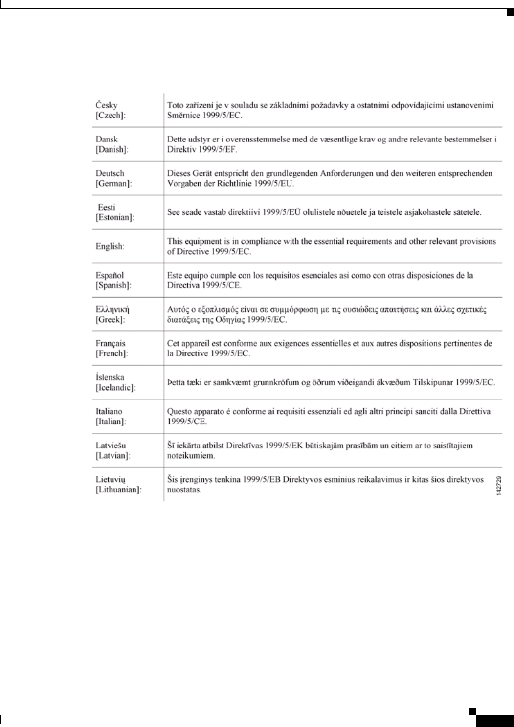
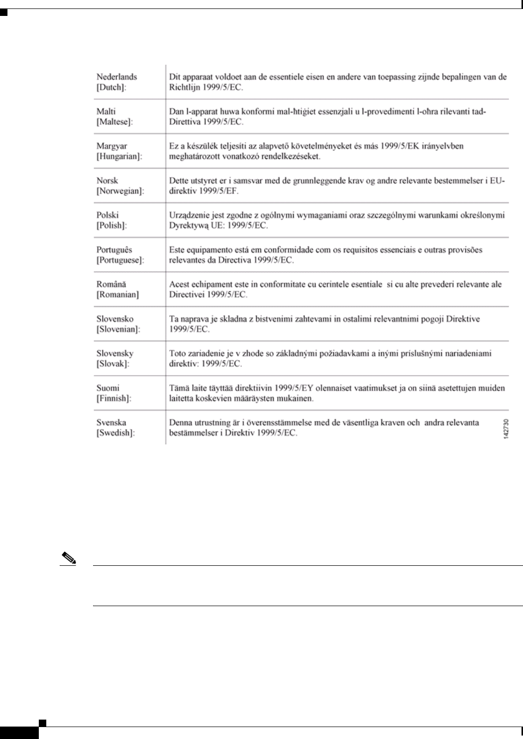
Declaration of Conformity with Regard to the R&TTE Directive 1999/5/EC
CISCO CONFIDENTIAL - Draft AA1
B-6
Cisco Aironet 1250 Series Access Point Hardware Installation Guide
OL-8247-01
Appendix B Declarations of Conformity and Regulatory Information
European Community, Switzerland, Norway, Iceland, and Liechtenstein
This device complies with the EMC requirements (EN 60601-1-2) of the Medical Directive 93/42/EEC.
For 2.4 GHz radios, the following standards were applied:
•Radio: EN 300.328-1, EN 300.328-2
•EMC: EN 301.489-1, EN 301.489-17
•Safety: EN 60950
Note This equipment is intended to be used in all EU and EFTA countries. Outdoor use may be restricted to
certain frequencies and/or may require a license for operation. For more details, contact Cisco Corporate
Compliance.

CISCO CONFIDENTIAL - Draft AA1
B-7
Cisco Aironet 1250 Series Access Point Hardware Installation Guide
OL-8247-01
Appendix B Declarations of Conformity and Regulatory Information
Declaration of Conformity for RF Exposure
For 54 Mbps, 5 GHz access points, the following standards were applied:
•Radio: EN 301.893
•EMC: EN 301.489-1, EN 301.489-17
•Safety: EN 60950
The following CE mark is affixed to the access point with a 2.4 GHz radio and a 54 Mbps, 5 GHz radio:
Declaration of Conformity for RF Exposure
The radio has been found to be compliant to the requirements set forth in CFR 47 Sections 2.1091, and
15.247 (b) (4) addressing RF Exposure from radio frequency devices as defined in Evaluating
Compliance with FCC Guidelines for Human Exposure to Radio Frequency Electromagnetic Fields. The
equipment shoud be installed more than 20 cm (7.9 in.) from your body or nearby persons.
The access point must be installed to maintain a minimum 20 cm (7.9 in.) co-located separation distance
from other FCC approved indoor/outdoor antennas used with the access point. Any antennas or
transmitters not approved by the FCC cannot be co-located with the access point. The access point’s
co-located 2.4 GHz and 5 GHz integrated antennas support a minimum separation distance of
8 cm (3.2 in.) and are compliant with the applicable FCC RF exposure limit when transmitting
simultaneously.
Note Dual antennas used for diversity operation are not considered co-located.
CISCO CONFIDENTIAL - Draft AA1
B-8
Cisco Aironet 1250 Series Access Point Hardware Installation Guide
OL-8247-01
Appendix B Declarations of Conformity and Regulatory Information
Guidelines for Operating Cisco Aironet Access Points in Japan
Guidelines for Operating Cisco Aironet Access Points in Japan
This section provides guidelines for avoiding interference when operating Cisco Aironet access points
in Japan. These guidelines are provided in both Japanese and English.
Japanese Translation
English Translation
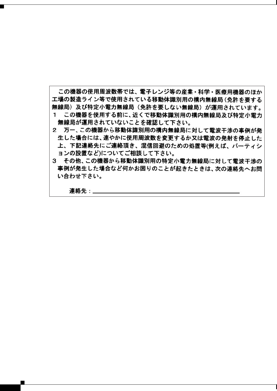
This equipment operates in the same frequency bandwidth as industrial, scientific, and medical devices
such as microwave ovens and mobile object identification (RF-ID) systems (licensed premises radio
stations and unlicensed specified low-power radio stations) used in factory production lines.
1. Before using this equipment, make sure that no premises radio stations or specified low-power radio
stations of RF-ID are used in the vicinity.
2. If this equipment causes RF interference to a premises radio station of RF-ID, promptly change the
frequency or stop using the device; contact the number below and ask for recommendations on
avoiding radio interference, such as setting partitions.
3. If this equipment causes RF interference to a specified low-power radio station of RF-ID, contact
the number below.
Contact Number: 03-5549-6500
03-5549-6500
4
3768
CISCO CONFIDENTIAL - Draft AA1
B-9
Cisco Aironet 1250 Series Access Point Hardware Installation Guide
OL-8247-01
Appendix B Declarations of Conformity and Regulatory Information
Administrative Rules for Cisco Aironet Access Points in Taiwan
Administrative Rules for Cisco Aironet Access Points in Taiwan
This section provides administrative rules for operatingCisco Aironet access points inTaiwan. The rules
are provided in both Chinese and English.
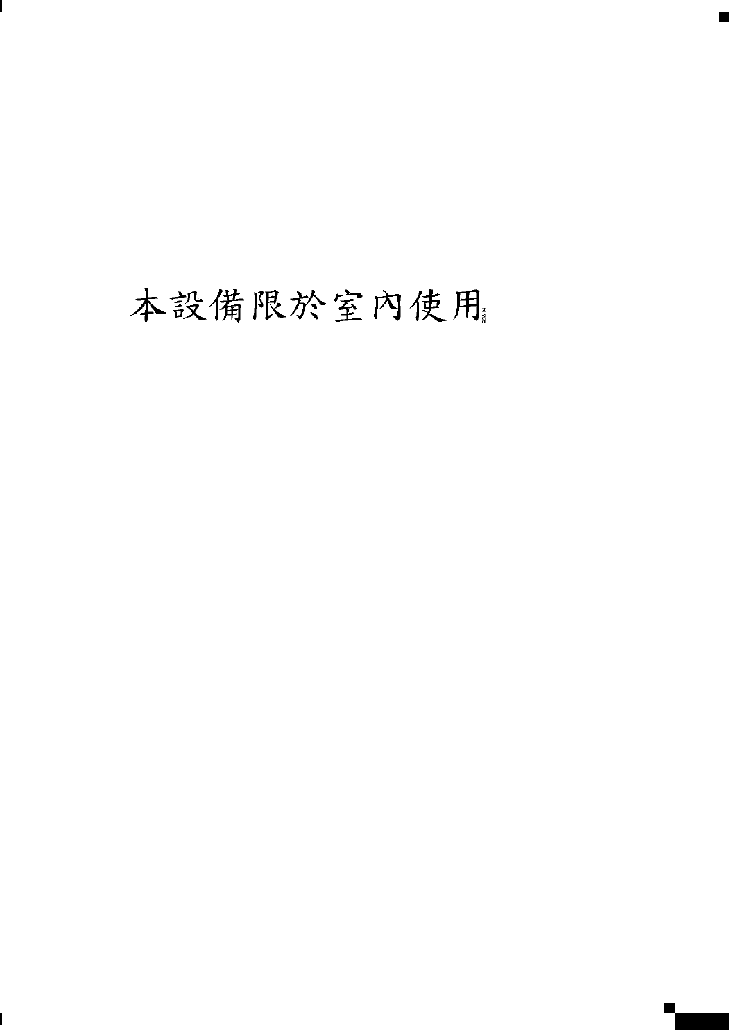
Access Points with IEEE 802.11a Radios
Chinese Translation
English Translation
This equipment is limited for indoor use.
CISCO CONFIDENTIAL - Draft AA1
B-10
Cisco Aironet 1250 Series Access Point Hardware Installation Guide
OL-8247-01
Appendix B Declarations of Conformity and Regulatory Information
Administrative Rules for Cisco Aironet Access Points in Taiwan
All Access Points
Chinese Translation
English Translation
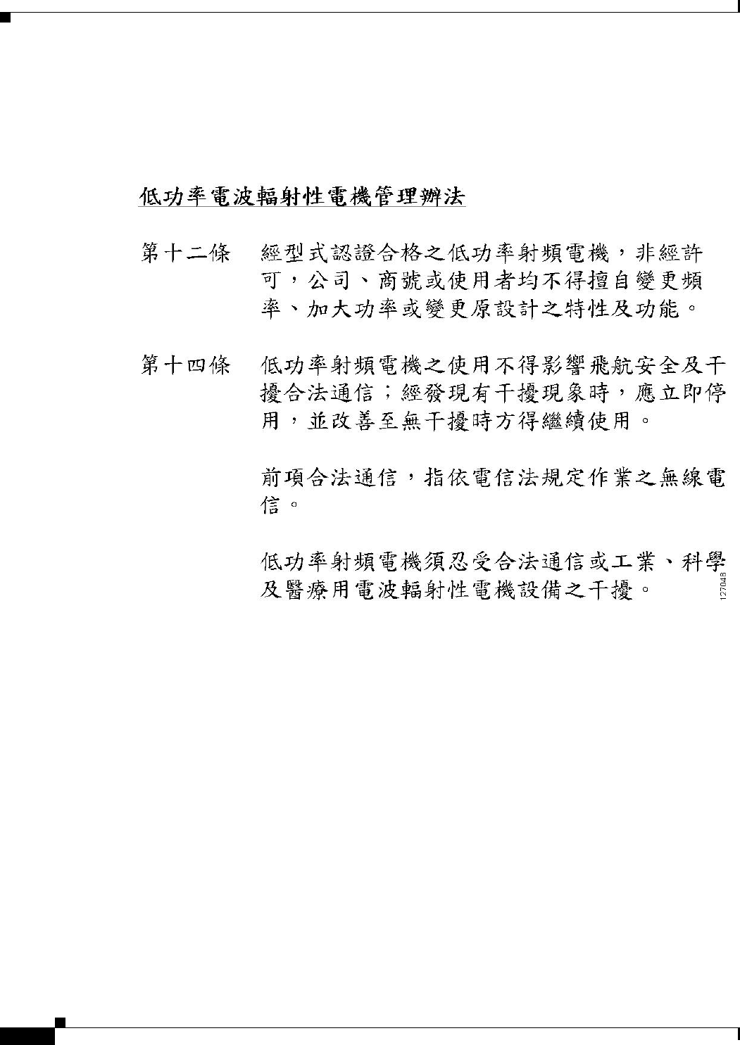
Administrative Rules for Low-power Radio-Frequency Devices
Article 12
For those low-power radio-frequency devices that have already received a type-approval, companies,
business units or users should not change its frequencies, increase its power or change its original
features and functions.
Article 14
The operation of the low-power radio-frequency devices is subject to the conditions that no harmful
interference is caused to aviation safety and authorized radio station; and if interference is caused, the
user must stop operating the device immediately and can't re-operate it until the harmful interference is
clear.
The authorized radio station means a radio-communication service operating in accordance with the
Communication Act.
The operation of the low-power radio-frequency devices is subject to the interference caused by the
operation of an authorized radio station, by another intentional or unintentional radiator, by industrial,
scientific and medical (ISM) equipment, or by an incidental radiator.

CISCO CONFIDENTIAL - Draft AA1
B-11
Cisco Aironet 1250 Series Access Point Hardware Installation Guide
OL-8247-01
Appendix B Declarations of Conformity and Regulatory Information
Declaration of Conformity Statements
Declaration of Conformity Statements
All the Declaration of Conformity statements related to this product can be found at the following URL:
http://www.ciscofax.com
Declaration of Conformity Statements for European Union
Countries
The Declaration of Conformity statement for the European Union countries is listed below:

CISCO CONFIDENTIAL - Draft AA1
B-12
Cisco Aironet 1250 Series Access Point Hardware Installation Guide
OL-8247-01
Appendix B Declarations of Conformity and Regulatory Information
Declaration of Conformity Statements for European Union Countries

CHAPTER
CISCO CONFIDENTIAL—DRAFT 1
5-1
Channels and Maximum Power Settings for Cisco Aironet Autonomous Access Points and Bridges
OL-11142-01
5
Cisco Aironet 1250 Series Autonomous
Access Point
This section lists the 1250 series autonomous access point (model: AIR-AP1251)2.4-GHz pre-n IEEE
802.11n and the 5-GHz pre-n IEEE 802.11n channels and maximum power levels supported by the
world’s regulatory domains. The following topics are covered in this section:
•Channels and Maximum Power Levels, page 5-2
•Special Country Restrictions, page 5-17
•Changing Autonomous Access Point Output Power, page 5-17
CISCO CONFIDENTIAL—DRAFT 1
5-2
Channels and Maximum Power Settings for Cisco Aironet Autonomous Access Points and Bridges
OL-11142-01
Chapter 5 Cisco Aironet 1250 Series Autonomous Access Point
Channels and Maximum Power Levels
Channels and Maximum Power Levels
2.4 GHz Band (pre-n IEEE 802.11n)
An improper combination of power level and antenna gain can result in equivalent isotropic radiated
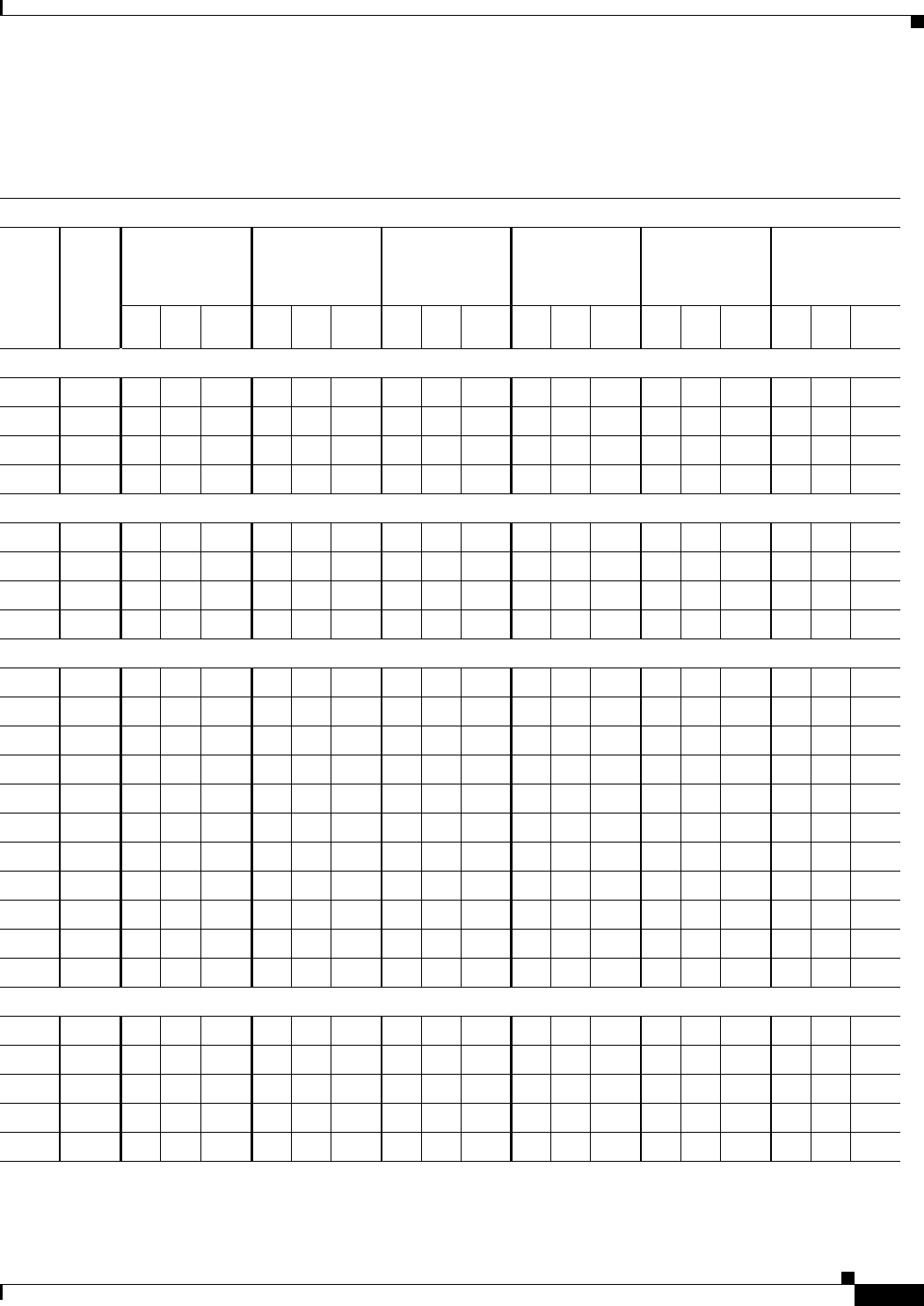
power (EIRP) above the amount allowed per regulatory domain. Table 5-1 indicates the channel
identifiers, channel center frequencies, and maximum power levels for each channel allowed by the
–A regulatory domain for a 2.4-GHz radio with up to 10-dBi antennas.
Table 5-1 Channels and Maximum Conducted Power in the –A Regulatory Domain with up to 10-dBi Antennas
Maximum Conducted Power Levels (dBm) in the –A Regulatory Domain for the 2.4-GHz Radio with up to 10-dBi Antennas
Freq
(MHz)
Center
Channel
802.11b
Single Antenna
1 to 11 Mbps
802.11g
Single Antenna
6 to 54 Mbps
802.11g
Dual Antennas
6 to 54 Mbps
802.11g
Dual Antennas
with Beam
Forming
HT-20 MHz
Dual Antennas
M0 to M15
HT-40 MHz
Dual Antennas
M0 to M15
20
MHz
40
MHz
Tx
A
Tx
B
Total
Power
Tx
A
Tx
B
Total
Power
Tx
A
Tx
B
Total
Power
Tx
A
Tx
B
Total
Power
Tx
A
Tx
B
Total
Power
Tx
A
Tx
B
Total
Power
2412 1 3 20 OFF 20 17 OFF 17 17 17 20 17 17 20 17 17 20 14 14 17
2417 2 4 20 OFF 20 17 OFF 17 17 17 20 17 17 20 17 17 20 14 14 17
2422 3 5 20 OFF 20 17 OFF 17 17 17 20 17 17 20 17 17 20 14 14 17
2427 4 6 20 OFF 20 17 OFF 17 17 17 20 17 17 20 17 17 20 14 14 17
243253, 720OFF2017OFF17171720171720171720141417
243764, 823OFF2320OFF20202023202023171720171720
244275, 920OFF2017OFF17171720171720171720141417
2447 8 6 20 OFF 20 17 OFF 17 17 17 20 17 17 20 17 17 20 14 14 17
2452 9 7 20 OFF 20 17 OFF 17 17 17 20 17 17 20 17 17 20 14 14 17
245710820OFF2017OFF17171720171720171720141417
246211920OFF2017OFF17171720171720171720141417
2467––––––––––––––––––––
2472––––––––––––––––––––
2484––––––––––––––––––––
CISCO CONFIDENTIAL—DRAFT 1
5-3
Channels and Maximum Power Settings for Cisco Aironet Autonomous Access Points and Bridges
OL-11142-01
Chapter 5 Cisco Aironet 1250 Series Autonomous Access Point
Channels and Maximum Power Levels
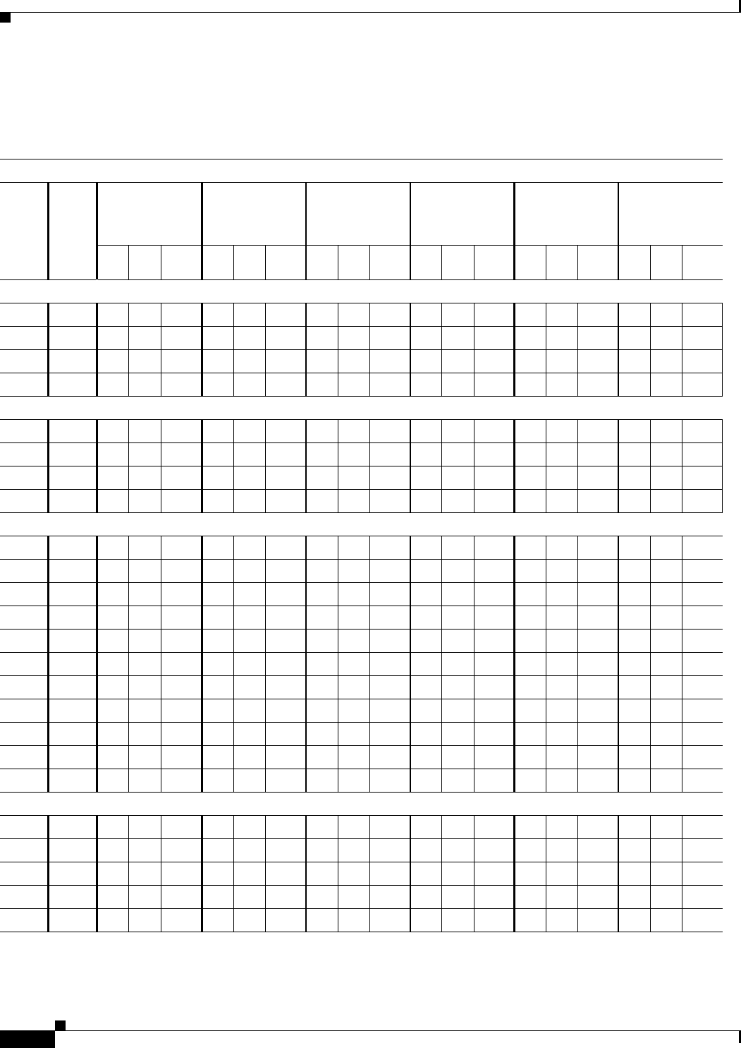
Table 5-2 indicates the channel identifiers, channel center frequencies, and maximum power levels for
each channel allowed by the –E regulatory domain for a 2.4-GHz radio with up to 3-dBi antennas.
Table 5-2 Channels and Maximum Conducted Power for –E Regulatory Domain with up to 3-dBi Antennas
Maximum Conducted Power Levels (dBm) in the –E Regulatory Domain for the 2.4-GHz Radio with up to 3-dBi Anetnnas
Freq
(MHz)
Center
Channel
802.11b
Single Antenna
1 to 11 Mbps
802.11g
Single Antenna
6 to 54 Mbps
802.11g
Dual Antennas
6 to 54 Mbps
802.11g
Dual Antennas
with Beam
Forming
HT-20 MHz
Dual Antennas
M0 to M15
HT-40 MHz
Dual Antennas
M0 to M15
20
MHz
40
MHz
Tx
A
Tx
B
Total
Power
Tx
A
Tx
B
Total
Power
Tx
A
Tx
B
Total
Power
Tx
A
Tx
B
Total
Power
Tx
A
Tx
B
Total
Power
Tx
A
Tx
B
Total
Power
2412 1 3 17 OFF 17 17 OFF 17 14 14 17 11 11 14 14 14 17 14 14 17
2417 2 4 17 OFF 17 17 OFF 17 14 14 17 11 11 14 14 14 17 14 14 17
2422 3 5 17 OFF 17 17 OFF 17 14 14 17 11 11 14 14 14 17 14 14 17
2427 4 6 17 OFF 17 17 OFF 17 14 14 17 11 11 14 14 14 17 14 14 17
243253, 717OFF1717OFF17141417111114141417141417
243764, 817OFF1717OFF17141417111114141417141417
244275, 917OFF1717OFF17141417111114141417141417
2447 8 6 17 OFF 17 17 OFF 17 14 14 17 11 11 14 14 14 17 14 14 17
2452 9 7 17 OFF 17 17 OFF 17 14 14 17 11 11 14 14 14 17 14 14 17
245710817OFF1717OFF17141417111114141417141417
246211917OFF1717OFF17141417111114141417141417
246712–17OFF1717OFF17141417111114141417 – – –
247213–17OFF1717OFF17141417111114141417 – – –
2484––––––––––––––––––––
CISCO CONFIDENTIAL—DRAFT 1
5-4
Channels and Maximum Power Settings for Cisco Aironet Autonomous Access Points and Bridges
OL-11142-01
Chapter 5 Cisco Aironet 1250 Series Autonomous Access Point
Channels and Maximum Power Levels
Table 5-3 indicates the channel identifiers, channel center frequencies, and maximum power levels for
each channel allowed by the –E regulatory domain for a 2.4-GHz radio with up to 6-dBi antennas.
Table 5-3 Channels and Maximum Conducted Power in the –E Regulatory Domain with up to 6-dBi Antennas
Maximum Conducted Power Levels (dBm) in the –E Regulatory Domain for the 2.4-GHz Radio with up to 6-dBi Antennas
Freq
(MHz)
Center
Channel
802.11b
Single Antenna
1 to 11 Mbps
802.11g
Single Antenna
6 to 54 Mbps
802.11g
Dual Antennas
6 to 54 Mbps
802.11g
Dual Antennas
with Beam
Forming
HT-20 MHz
Dual Antennas
M0 to M15
HT-40 MHz
Dual Antennas
M0 to M15
20
MHz
40
MHz
Tx
A
Tx
B
Total
Power
Tx
A
Tx
B
Total
Power
Tx
A
Tx
B
Total
Power
Tx
A
Tx
B
Total
Power
Tx
A
Tx
B
Total
Power
Tx
A
Tx
B
Total
Power
2412 1 3 14 OFF 14 14 OFF 14 11 11 14 8 8 11 11 11 14 11 11 14
2417 2 4 14 OFF 14 14 OFF 14 11 11 14 8 8 11 11 11 14 11 11 14
2422 3 5 14 OFF 14 14 OFF 14 11 11 14 8 8 11 11 11 14 11 11 14
2427 4 6 14 OFF 14 14 OFF 14 11 11 14 8 8 11 11 11 14 11 11 14
243253, 714OFF1414OFF14111114 88 11111114111114
243764, 814OFF1414OFF14111114 88 11111114111114
244275, 914OFF1414OFF14111114 88 11111114111114
2447 8 6 14 OFF 14 14 OFF 14 11 11 14 8 8 11 11 11 14 11 11 14
2452 9 7 14 OFF 14 14 OFF 14 11 11 14 8 8 11 11 11 14 11 11 14
245710814OFF1414OFF14111114 88 11111114111114
246211914OFF1414OFF14111114 88 11111114111114
246712–14OFF1414OFF14111114 88 11111114 –– –
247213–14OFF1414OFF14111114 88 11111114 –– –
2484––––––––––––––––––––

CISCO CONFIDENTIAL—DRAFT 1
5-5
Channels and Maximum Power Settings for Cisco Aironet Autonomous Access Points and Bridges
OL-11142-01
Chapter 5 Cisco Aironet 1250 Series Autonomous Access Point
Channels and Maximum Power Levels
Table 5-4 indicates the channel identifiers, channel center frequencies, and maximum power levels for
each channel allowed by the –E regulatory domain for a 2.4-GHz radio with up to 9-dBi antennas.
Table 5-4 Channels and Maximum Conducted Power in the –E Regulatory Domain with up to 9-dBi Antennas
Maximum Conducted Power Levels (dBm) in the –E Regulatory Domain for the 2.4-GHz Radio with up to 9-dBi Antennas
Freq
(MHz)
Center
Channel
802.11b
Single Antenna
1 to 11 Mbps
802.11g
Single Antenna
6 to 54 Mbps
802.11g
Dual Antennas
6 to 54 Mbps
802.11g
Dual Antennas
with Beam
Forming
HT-20 MHz
Dual Antennas
M0 to M15
HT-40 MHz
Dual Antennas
M0 to M15
20
MHz
40
MHz
Tx
A
Tx
B
Total
Power
Tx
A
Tx
B
Total
Power
Tx
A
Tx
B
Total
Power
Tx
A
Tx
B
Total
Power
Tx
A
Tx
B
Total
Power
Tx
A
Tx
B
Total
Power
2412 1 3 11 OFF 11 11 OFF 11 8 8 11 5 5 8 8 8 11 8 8 11
2417 2 4 11 OFF 11 11 OFF 11 8 8 11 5 5 8 8 8 11 8 8 11
2422 3 5 11 OFF 11 11 OFF 11 8 8 11 5 5 8 8 8 11 8 8 11
2427 4 6 11 OFF 11 11 OFF 11 8 8 11 5 5 8 8 8 11 8 8 11
2432 5 3, 7 11 OFF 11 11 OFF 11 8 8 11 5 5 8 8 8 11 8 8 11
2437 6 4, 8 11 OFF 11 11 OFF 11 8 8 11 5 5 8 8 8 11 8 8 11
2442 7 5, 9 11 OFF 11 11 OFF 11 8 8 11 5 5 8 8 8 11 8 8 11
2447 8 6 11 OFF 11 11 OFF 11 8 8 11 5 5 8 8 8 11 8 8 11
2452 9 7 11 OFF 11 11 OFF 11 8 8 11 5 5 8 8 8 11 8 8 11
2457 10 8 11 OFF 11 11 OFF 11 8 8 11 5 5 8 8 8 11 8 8 11
2462 11 9 11 OFF 11 11 OFF 11 8 8 11 5 5 8 8 8 11 8 8 11
2467 12 – 11 OFF 11 11 OFF 11 8 8 11 5 5 8 8 8 11 – – –
2472 13 – 11 OFF 11 11 OFF 11 8 8 11 5 5 8 8 8 11 – – –
2484––––––––––––––––––––

CISCO CONFIDENTIAL—DRAFT 1
5-6
Channels and Maximum Power Settings for Cisco Aironet Autonomous Access Points and Bridges
OL-11142-01
Chapter 5 Cisco Aironet 1250 Series Autonomous Access Point
Channels and Maximum Power Levels
Table 5-5 indicates the channel identifiers, channel center frequencies, and maximum power levels for
each channel allowed by the –E regulatory domain for a 2.4-GHz radio with up to 10-dBi antennas.
Table 5-5 Channels and Maximum Conducted Power in the –E Regulatory Domain with up to 10-dBi Antennas
Maximum Conducted Power Levels (dBm) in the –E Regulatory Domain for the 2.4-GHz Radio with up to 10-dBi Anetnnas
Freq
(MHz)
Center
Channel
802.11b
Single Antenna
1 to 11 Mbps
802.11g
Single Antenna
6 to 54 Mbps
802.11g
Dual Antennas
6 to 54 Mbps
802.11g
Dual Antennas
with Beam
Forming
HT-20 MHz
Dual Antennas
M0 to M15
HT-40 MHz
Dual Antennas
M0 to M15
20
MHz
40
MHz
Tx
A
Tx
B
Total
Power
Tx
A
Tx
B
Total
Power
Tx
A
Tx
B
Total
Power
Tx
A
Tx
B
Total
Power
Tx
A
Tx
B
Total
Power
Tx
A
Tx
B
Total
Power
2412138OFF88OFF8558225558558
2417248OFF88OFF8558225558558
2422358OFF88OFF8558225558558
2427468OFF88OFF8558225558558
243253, 78OFF88OFF8558225558558
243764, 88OFF88OFF8558225558558
244275, 98OFF88OFF8558225558558
2447868OFF88OFF8558225558558
2452978OFF88OFF8558225558558
24571088OFF88OFF8558225558558
24621198OFF88OFF8558225558558
246712–8OFF88OFF8558225558–––
247213–8OFF88OFF8558225558–––
2484––––––––––––––––––––

CISCO CONFIDENTIAL—DRAFT 1
5-7
Channels and Maximum Power Settings for Cisco Aironet Autonomous Access Points and Bridges
OL-11142-01
Chapter 5 Cisco Aironet 1250 Series Autonomous Access Point
Channels and Maximum Power Levels
Table 5-6 indicates the channel identifiers, channel center frequencies, and maximum power levels for
each channel allowed by the –P regulatory domain for a 2.4-GHz radio with up to 10-dBi antennas.
5 GHz Band (pre-n IEEE 802.11n)
An improper combination of power level and antenna gain can result in equivalent isotropic radiated
power (EIRP) above the amount allowed per regulatory domain.
Note Dynamic Frequency Selection (DFS) operation and operation from 5500 to 5700 MHz has not been
authorized as required by the rules of the Federal Communications Commission and is not supported in
the -A regulatory domain until authorization is obtained.
Table 5-6 Channels and Maximum Conducted Power for the 2.4-GHz Radio with up to 10-dBi Antennas
Maximum Conducted Power Levels (dBm) in the –P Regulatory Domain for the 2.4 GHz Radio with up to 10 dBi Antennas
Freq
(MHz)
Center
Channel
802.11b
Single Antenna
1 to 11 Mbps
802.11g
Single Antenna
6 to 54 Mbps
802.11g
Dual Antennas
6 to 54 Mbps
802.11g
Dual Antennas
with Beam
Forming
HT-20 MHz
Dual Antennas
M0 to M15
HT-40 MHz
Dual Antennas
M0 to M15
20
MHz
40
MHz
Tx
A
Tx
B
Total
Power
Tx
A
Tx
B
Total
Power
Tx
A
Tx
B
Total
Power
Tx
A
Tx
B
Total
Power
Tx
A
Tx
B
Total
Power
Tx
A
Tx
B
Total
Power
2412 1 3 14 OFF 14 17 OFF 17 14 14 17 11 11 14 14 14 17 17 17 20
2417 2 4 14 OFF 14 17 OFF 17 14 14 17 11 11 14 14 14 17 17 17 20
2422 3 5 14 OFF 14 17 OFF 17 14 14 17 11 11 14 14 14 17 17 17 20
2427 4 6 14 OFF 14 17 OFF 17 14 14 17 11 11 14 14 14 17 17 17 20
243253, 714OFF1417OFF17141417111114141417171720
243764, 814OFF1417OFF17141417111114141417171720
244275, 914OFF1417OFF17141417111114141417171720
2447 8 6 14 OFF 14 17 OFF 17 14 14 17 11 11 14 14 14 17 17 17 20
2452 9 7 14 OFF 14 17 OFF 17 14 14 17 11 11 14 14 14 17 17 17 20
245710814OFF1417OFF17141417111114141417171720
246211914OFF1417OFF17141417111114141417171720
246712–14OFF1417OFF17141417111114141417 – – –
247213–14OFF1417OFF17141417111114141417 – – –
248414–14OFF14–––––––––––––––

CISCO CONFIDENTIAL—DRAFT 1
5-8
Channels and Maximum Power Settings for Cisco Aironet Autonomous Access Points and Bridges
OL-11142-01
Chapter 5 Cisco Aironet 1250 Series Autonomous Access Point
Channels and Maximum Power Levels
Table 5-7 indicates the channel identifiers, channel center frequencies, and maximum power levels for
each channel allowed by the –A regulatory domain for a 5-GHz radio with up to 6-dBi antennas.
Table 5-7 Channels and Maximum Conducted Power in the –A Regulatory Domain with up to 6-dBi Antennas
Maximum Conducted Power Levels (dBm) in the –A Regulatory Domain for the 5-GHz Radio with up to 6-dBi Antennas
Channel
ID
Freq
(MHz)
802.11a
Single Antenna
6 to 54 Mbps
802.11a
Dual Antennas
6 to 54 Mbps
802.11a
Dual Antennas with
Beam Forming
HT-20 MHz
Dual Antennas
M0 to M15
Duplicate
(2x20 MHz)
Dual Antennas
6 Mbps
HT-40 MHz
Dual Antennas
M0 to M15
Tx
A
Tx
B
Total
Power
Tx
A
Tx
B
Total
Power
Tx
A
Tx
B
Total
Power
Tx
A
Tx
B
Total
Power
Tx
A
Tx
B
Total
Power
Tx
A
Tx
B
Total
Power
5150-5250 MHz
36 5180 14OFF14111114 88 11111114111114111114
40 5200 14OFF14111114 88 11111114111114111114
44 5220 14OFF14111114 88 11111114111114111114
48 5240 14OFF14111114 88 11111114111114111114
5250 to 5350 MHz
52 5260 17OFF17171720141417171720171720171720
56 5280 17OFF17171720141417171720171720171720
60 5300 17OFF17171720141417171720111114111114
64 5320 17OFF17171720141417171720111114 111114
5470 to 5725 MHz
100 5500 17 OFF 17 17 OFF 20 14 14 17 17 17 20 14 14 17 14 14 17
104 5520 17 OFF 17 17 OFF 20 14 14 17 17 17 20 14 14 17 14 14 17
108 5540 17 OFF 17 17 OFF 20 14 14 17 17 17 20 17 17 20 17 17 20
112 5560 17 OFF 17 17 OFF 20 14 14 17 17 17 20 17 17 20 17 17 20
116 5580 17 OFF 17 17 OFF 20 14 14 17 17 17 20 17 17 20 17 17 20
120 5600 ––––––––––––––––––
124 5620 ––––––––––––––––––
128 5640 ––––––––––––––––––
132 5660 17OFF17171720141417171720171720171720
136 5680 17OFF17171720141417171720171720171720
140 5700 17OFF17171720141417171720 –– – –– –
5725 to 5850 MHz
149 5745 17OFF17171720171720171720171720171720
153 5765 17OFF17171720171720171720171720171720
157 5785 17OFF17171720171720171720171720171720
161 5805 17OFF17171720171720171720171720171720
165 5825 17OFF17171720171720171720 –– – –– –
CISCO CONFIDENTIAL—DRAFT 1
5-9
Channels and Maximum Power Settings for Cisco Aironet Autonomous Access Points and Bridges
OL-11142-01
Chapter 5 Cisco Aironet 1250 Series Autonomous Access Point
Channels and Maximum Power Levels
Table 5-8 indicates the channel identifiers, channel center frequencies, and maximum power levels for
each channel allowed by the –C regulatory domain for a 5-GHz radio with up to 6-dBi antennas.
Table 5-8 Channels and Maximum Conducted Power in the –C Regulatory Domain with up to 6-dBi Antennas
Maximum Conducted Power Levels (dBm) in the –C Regulatory Domain for a 5-GHz Radio with up to 6-dBi Antennas
Channel
ID
Freq
(MHz)
802.11a
Single Antenna
6 to 54 Mbps
802.11a
Dual Antennas
6 to 54 Mbps
802.11a
Dual Antennas with
Beam Forming
HT-20 MHz
Dual Antennas
M0 to M15
Duplicate
(2x20 MHz)
Dual Antennas
6 Mbps
HT-40 MHz
Dual Antennas
M0 to M15
Tx
A
Tx
B
Total
Power
Tx
A
Tx
B
Total
Power
Tx
A
Tx
B
Total
Power
Tx
A
Tx
B
Total
Power
Tx
A
Tx
B
Total
Power
Tx
A
Tx
B
Total
Power
UNII-1 (5150-5250 MHz)
365180 ––––––––––––––––––
405200 ––––––––––––––––––
445220 ––––––––––––––––––
485240 ––––––––––––––––––
5250 to 5350 MHz
525260 ––––––––––––––––––
565280 ––––––––––––––––––
605300 ––––––––––––––––––
645320 ––––––––––––––––––
5470 to 5725 MHz
1005500––––––––––––––––––
1045520––––––––––––––––––
1085540––––––––––––––––––
1125560––––––––––––––––––
1165580––––––––––––––––––
1205600––––––––––––––––––
1245620––––––––––––––––––
1285640––––––––––––––––––
1325660––––––––––––––––––
1365680––––––––––––––––––
1405700––––––––––––––––––
5725 to 5850 MHz
149 5745 17 OFF 17 17 17 20 17 17 20 17 17 20 17 17 20 17 17 20
153 5765 17 OFF 17 17 17 20 17 17 20 17 17 20 17 17 20 17 17 20
157 5785 17 OFF 17 17 17 20 17 17 20 17 17 20 17 17 20 17 17 20
161 5805 17 OFF 17 17 17 20 17 17 20 17 17 20 17 17 20 17 17 20
165 5825 17 OFF 17 17 17 20 17 17 20 17 17 20 – – – – – –
CISCO CONFIDENTIAL—DRAFT 1
5-10
Channels and Maximum Power Settings for Cisco Aironet Autonomous Access Points and Bridges
OL-11142-01
Chapter 5 Cisco Aironet 1250 Series Autonomous Access Point
Channels and Maximum Power Levels
Table 5-9 indicates the channel identifiers, channel center frequencies, and maximum power levels for
each channel allowed by the –E regulatory domain for a 5-GHz radio with up to 6-dBi antennas.
Table 5-9 Channels and Maximum Conducted Power in the –E Regulatory Domain with up to 6-dBi Antennas
Maximum Conducted Power Levels (dBm) in the –E Regulatory Domain for the 5-GHz Radio with up to 6-dBi Antennas
Channel
ID
Freq
(MHz)
802.11a
Single Antenna
6 to 54 Mbps
802.11a
Dual Antennas
6 to 54 Mbps
802.11a
Dual Antennas with
Beam Forming
HT-20 MHz
Dual Antennas
M0 to M15
Duplicate
(2x20 MHz)
Dual Antennas
6 Mbps
HT-40 MHz
Dual Antennas
M0 to M15
Tx
A
Tx
B
Total
Power
Tx
A
Tx
B
Total
Power
Tx
A
Tx
B
Total
Power
Tx
A
Tx
B
Total
Power
Tx
A
Tx
B
Total
Power
Tx
A
Tx
B
Total
Power
UNII-1 (5150-5250 MHz)
36 5180 17OFF17141417111114141417141417141417
40 5200 17OFF17141417111114141417141417141417
44 5220 17OFF17141417111114141417141417141417
48 5240 17OFF17141417111114141417141417141417
5250 to 5350 MHz
52 5260 17OFF17141417111114141417141417141417
56 5280 17OFF17141417111114141417141417141417
60 5300 17OFF17141417111114141417141417141417
64 5320 17OFF17141417111114141417141417141417
5470 to 5725 MHz
100 5500 17OFF17171720171720171720171720171720
104 5520 17OFF17171720171720171720171720171720
108 5540 17OFF17171720171720171720171720171720
112 5560 17OFF17171720171720171720171720171720
116 5580 17OFF17171720171720171720171720171720
120 5600 17OFF17171720171720171720171720171720
124 5620 17OFF17171720171720171720171720171720
128 5640 17OFF17171720171720171720171720171720
132 5660 17OFF17171720171720171720171720171720
136 5680 17OFF17171720171720171720171720171720
140 5700 17OFF17171720171720171720
5725 to 5850 MHz
149 5745 ––––––––––––––––––
153 5765 ––––––––––––––––––
157 5785 ––––––––––––––––––
161 5805 ––––––––––––––––––
165 5825 ––––––––––––––––––
CISCO CONFIDENTIAL—DRAFT 1
5-11
Channels and Maximum Power Settings for Cisco Aironet Autonomous Access Points and Bridges
OL-11142-01
Chapter 5 Cisco Aironet 1250 Series Autonomous Access Point
Channels and Maximum Power Levels
Table 5-10 indicates the channel identifiers, channel center frequencies, and maximum power levels for
each channel allowed by the –I regulatory domain for a 5-GHz radio with up to 6-dBi antenna.s
Table 5-10 Channels and Maximum Conducted Power in the –I Regulatory Domain with up to 6-dBi Antennas
Maximum Conducted Power Levels (dBm) in the –I Regulatory Domain for a 5-GHz Radio with up to 6-dBi Antennas
Channel
ID
Freq
(MHz)
802.11a
Single Antenna
6 to 54 Mbps
802.11a
Dual Antennas
6 to 54 Mbps
802.11a
Dual Antennas with
Beam Forming
HT-20 MHz
Dual Antennas
M0 to M15
Duplicate
(2x20 MHz)
Dual Antennas
6 Mbps
HT-40 MHz
Dual Antennas
M0 to M15
Tx
A
Tx
B
Total
Power
Tx
A
Tx
B
Total
Power
Tx
A
Tx
B
Total
Power
Tx
A
Tx
B
Total
Power
Tx
A
Tx
B
Total
Power
Tx
A
Tx
B
Total
Power
UNII-1 (5150-5250 MHz)
36 5180 17OFF17141417111114141417141417141417
40 5200 17OFF17141417111114141417141417141417
44 5220 17OFF17141417111114141417141417141417
48 5240 17OFF17141417111114141417141417141417
5250 to 5350 MHz
52 5260 17OFF17141417111114141417141417141417
56 5280 17OFF17141417111114141417141417141417
60 5300 17OFF17141417111114141417141417141417
64 5320 17OFF17141417111114141417141417141417
5470 to 5725 MHz
100 5500 ––––––––––––––––––
104 5520 ––––––––––––––––––
108 5540 ––––––––––––––––––
112 5560 ––––––––––––––––––
116 5580 ––––––––––––––––––
120 5600 ––––––––––––––––––
124 5620 ––––––––––––––––––
128 5640 ––––––––––––––––––
132 5660 ––––––––––––––––––
136 5680 ––––––––––––––––––
140 5700 ––––––––––––––––––
5725 to 5850 MHz
149 5745 ––––––––––––––––––
153 5765 ––––––––––––––––––
157 5785 ––––––––––––––––––
161 5805 ––––––––––––––––––
165 5825 ––––––––––––––––––

CISCO CONFIDENTIAL—DRAFT 1
5-12
Channels and Maximum Power Settings for Cisco Aironet Autonomous Access Points and Bridges
OL-11142-01
Chapter 5 Cisco Aironet 1250 Series Autonomous Access Point
Channels and Maximum Power Levels
Table 5-11 indicates the channel identifiers, channel center frequencies, and maximum power levels for
each channel allowed by the –K regulatory domain for a 5-GHz radio with up to 6-dBi antennas.
Table 5-11 Channels and Maximum Conducted Power in the –K Regulatory Domain with up to 6-dBi Antennas
Maximum Conducted Power Levels (dBm) in the –K Regulatory Domain for a 5-GHz Radio with up to 6-dBi Antennas
Channel
ID
Freq
(MHz)
802.11a
Single Antenna
6 to 54 Mbps
802.11a
Dual Antennas
6 to 54 Mbps
802.11a
Dual Antennas with
Beam Forming
HT-20 MHz
Dual Antennas
M0 to M15
Duplicate
(2x20 MHz)
Dual Antennas
6 Mbps
HT-40 MHz
Dual Antennas
M0 to M15
Tx
A
Tx
B
Total
Power
Tx
A
Tx
B
Total
Power
Tx
A
Tx
B
Total
Power
Tx
A
Tx
B
Total
Power
Tx
A
Tx
B
Total
Power
Tx
A
Tx
B
Total
Power
UNII-1 (5150-5250 MHz)
36 5180 14OFF14881155 8 881188118811
40 5200 14OFF14881155 8 881188118811
44 5220 14OFF14881155 8 881188118811
48 5240 14OFF14881155 8 881188118811
5250 to 5350 MHz
52 5260 17OFF17171720141417171720171720171720
56 5280 17OFF17171720141417171720171720171720
60 5300 17OFF17171720141417171720171720171720
64 5320 17OFF17171720141417171720171720171720
5470 to 5725 MHz
100 5500 17OFF17171720141417171720171720171720
104 5520 17OFF17171720141417171720171720171720
108 5540 17OFF17171720141417171720171720171720
112 5560 17OFF17171720141417171720171720171720
116 5580 17OFF17171720141417171720171720171720
120 5600 ––––––––––––––––––
124 5620 ––––––––––––––––––
128 5640 ––––––––––––––––––
132 5660 ––––––––––––––––––
136 5680 ––––––––––––––––––
140 5700 ––––––––––––––––––
5725 to 5850 MHz
149 5745 17OFF17171720171720171720171720171720
153 5765 17OFF17171720171720171720171720171720
157 5785 17OFF17171720171720171720171720171720
161 5805 17OFF17171720171720171720171720171720
165 5825 17OFF17171720171720171720 –– – –– –

CISCO CONFIDENTIAL—DRAFT 1
5-13
Channels and Maximum Power Settings for Cisco Aironet Autonomous Access Points and Bridges
OL-11142-01
Chapter 5 Cisco Aironet 1250 Series Autonomous Access Point
Channels and Maximum Power Levels
Table 5-12 indicates the channel identifiers, channel center frequencies, and maximum power levels for
each channel allowed by the –N regulatory domain for a 5-GHz radio with up to 6-dBi antennas.
Table 5-12 Channels and Maximum Conducted Power in the –N Regulatory Domain with up to 6-dBi Antennas
Maximum Conducted Power Levels (dBm) in the –N Regulatory Domain for a 5-GHz Radio with up to 6-dBi Antennas
Channel
ID
Freq
(MHz)
802.11a
Single Antenna
6 to 54 Mbps
802.11a
Dual Antennas
6 to 54 Mbps
802.11a
Dual Antennas with
Beam Forming
HT-20 MHz
Dual Antennas
M0 to M15
Duplicate
(2x20 MHz)
Dual Antennas
6 Mbps
HT-40 MHz
Dual Antennas
M0 to M15
Tx
A
Tx
B
Total
Power
Tx
A
Tx
B
Total
Power
Tx
A
Tx
B
Total
Power
Tx
A
Tx
B
Total
Power
Tx
A
Tx
B
Total
Power
Tx
A
Tx
B
Total
Power
UNII-1 (5150-5250 MHz)
36 5180 14OFF14111114 88 11111114111114111114
40 5200 14OFF14111114 88 11111114111114111114
44 5220 14OFF14111114 88 11111114111114111114
48 5240 14OFF14111114 88 11111114111114111114
5250 to 5350 MHz
52 5260 17OFF17141417111114141417141417141417
56 5280 17OFF17141417111114141417141417141417
60 5300 17OFF17141417111114141417111114111114
64 5320 11OFF11141417111114141417111114111114
5470 to 5725 MHz
100 5500 ––––––––––––––––––
104 5520 ––––––––––––––––––
108 5540 ––––––––––––––––––
112 5560 ––––––––––––––––––
116 5580 ––––––––––––––––––
120 5600 ––––––––––––––––––
124 5620 ––––––––––––––––––
128 5640 ––––––––––––––––––
132 5660 ––––––––––––––––––
136 5680 ––––––––––––––––––
140 5700 ––––––––––––––––––
5725 to 5850 MHz
149 5745 17OFF17171720171720171720171720171720
153 5765 17OFF17171720171720171720171720171720
157 5785 17OFF17171720171720171720171720171720
161 5805 17OFF17171720171720171720171720171720
165 5825 17OFF17171720171720171720 –– – –– –

CISCO CONFIDENTIAL—DRAFT 1
5-14
Channels and Maximum Power Settings for Cisco Aironet Autonomous Access Points and Bridges
OL-11142-01
Chapter 5 Cisco Aironet 1250 Series Autonomous Access Point
Channels and Maximum Power Levels
Table 5-13 indicates the channel identifiers, channel center frequencies, and maximum power levels for
each channel allowed by the –P regulatory domain for a 5-GHz radio with up to 6-dBi antennas.
Table 5-13 Channels and Maximum Conducted Power in the –P Regulatory Domain with up to 6-dBi Antennas
Maximum Conducted Power Levels (dBm) in the –P Regulatory Domain for the 5-GHz Radio with up to 6-dBi Antennas
Channel
ID
Freq
(MHz)
802.11a
Single Antenna
6 to 54 Mbps
802.11a
Dual Antennas
6 to 54 Mbps
802.11a
Dual Antennas with
Beam Forming
HT-20 MHz
Dual Antennas
M0 to M15
Duplicate
(2x20 MHz)
Dual Antennas
6 Mbps
HT-40 MHz
Dual Antennas
M0 to M15
Tx
A
Tx
B
Total
Power
Tx
A
Tx
B
Total
Power
Tx
A
Tx
B
Total
Power
Tx
A
Tx
B
Total
Power
Tx
A
Tx
B
Total
Power
Tx
A
Tx
B
Total
Power
UNII-1 (5150-5250 MHz)
36 5180 17OFF17171720141417171720171720171720
40 5200 17OFF17171720141417171720171720171720
44 5220 17OFF17171720141417171720171720171720
48 5240 17OFF17171720141417171720171720171720
5250 to 5350 MHz
52 5260 17OFF17141417111114141417141417141417
56 5280 17OFF17141417111114141417141417141417
60 5300 17OFF17141417111114141417141417141417
64 5320 17OFF17141417111114141417141417141417
5470 to 5725 MHz
100 5500 ––––––––––––––––––
104 5520 ––––––––––––––––––
108 5540 ––––––––––––––––––
112 5560 ––––––––––––––––––
116 5580 ––––––––––––––––––
120 5600 ––––––––––––––––––
124 5620 ––––––––––––––––––
128 5640 ––––––––––––––––––
132 5660 ––––––––––––––––––
136 5680 ––––––––––––––––––
140 5700 ––––––––––––––––––
5725 to 5850 MHz
149 5745 ––––––––––––––––––
153 5765 ––––––––––––––––––
157 5785 ––––––––––––––––––
161 5805 ––––––––––––––––––
165 5825 ––––––––––––––––––

CISCO CONFIDENTIAL—DRAFT 1
5-15
Channels and Maximum Power Settings for Cisco Aironet Autonomous Access Points and Bridges
OL-11142-01
Chapter 5 Cisco Aironet 1250 Series Autonomous Access Point
Channels and Maximum Power Levels
Table 5-14 indicates the channel identifiers, channel center frequencies, and maximum power levels for
each channel allowed by the –S regulatory domain for a 5-GHz radio with up to 6-dBi antennas.
Table 5-14 Channels and Maximum Conducted Power in the –S Regulatory Domain with up to 6-dBi Antennas
Maximum Conducted Power Levels (dBm) in the –S Regulatory Domain for a 5-GHz Radio with up to 6-dBi Antennas
Channel
ID
Freq
(MHz)
802.11a
Single Antenna
6 to 54 Mbps
802.11a
Dual Antennas
6 to 54 Mbps
802.11a
Dual Antennas with
Beam Forming
HT-20 MHz
Dual Antennas
M0 to M15
Duplicate
(2x20 MHz)
Dual Antennas
6 Mbps
HT-40 MHz
Dual Antennas
M0 to M15
Tx
A
Tx
B
Total
Power
Tx
A
Tx
B
Total
Power
Tx
A
Tx
B
Total
Power
Tx
A
Tx
B
Total
Power
Tx
A
Tx
B
Total
Power
Tx
A
Tx
B
Total
Power
UNII-1 (5150-5250 MHz)
36 5180 17OFF17141417111114141417141417141417
40 5200 17OFF17141417111114141417141417141417
44 5220 17OFF17141417111114141417141417141417
48 5240 17OFF17141417111114141417141417141417
5250 to 5350 MHz
52 5260 17OFF17141417111114141417141417141417
56 5280 17OFF17141417111114141417141417141417
60 5300 17OFF17141417111114141417141417141417
64 5320 17OFF17141417111114141417141417141417
5470 to 5725 MHz
100 5500 ––––––––––––––––––
104 5520 ––––––––––––––––––
108 5540 ––––––––––––––––––
112 5560 ––––––––––––––––––
116 5580 ––––––––––––––––––
120 5600 ––––––––––––––––––
124 5620 ––––––––––––––––––
128 5640 ––––––––––––––––––
132 5660 ––––––––––––––––––
136 5680 ––––––––––––––––––
140 5700 ––––––––––––––––––
5725 to 5850 MHz
149 5745 17OFF17171720171720171720171720171720
153 5765 17OFF17171720171720171720171720171720
157 5785 17OFF17171720171720171720171720171720
161 5805 17OFF17171720171720171720171720171720
165 5825 17OFF17171720171720171720 –– – –– –
CISCO CONFIDENTIAL—DRAFT 1
5-16
Channels and Maximum Power Settings for Cisco Aironet Autonomous Access Points and Bridges
OL-11142-01
Chapter 5 Cisco Aironet 1250 Series Autonomous Access Point
Channels and Maximum Power Levels
Table 5-7 indicates the channel identifiers, channel center frequencies, and maximum power levels for
each channel allowed by the –T regulatory domain for a 5-GHz radio with up to 6-dBi antennas.
Table 5-15 Channels and Maximum Conducted Power in the –T Regulatory Domain with up to 6-dBi Antennas
Maximum Conducted Power Levels (dBm) in the –T Regulatory Domain for a 5-GHz Radio with up to 6-dBi Antennas
Channel
ID
Freq
(MHz)
802.11a
Single Antenna
6 to 54 Mbps
802.11a
Dual Antennas
6 to 54 Mbps
802.11a
Dual Antennas with
Beam Forming
HT-20 MHz
Dual Antennas
M0 to M15
Duplicate
(2x20 MHz)
Dual Antennas
6 Mbps
HT-40 MHz
Dual Antennas
M0 to M15
Tx
A
Tx
B
Total
Power
Tx
A
Tx
B
Total
Power
Tx
A
Tx
B
Total
Power
Tx
A
Tx
B
Total
Power
Tx
A
Tx
B
Total
Power
Tx
A
Tx
B
Total
Power
UNII-1 (5150-5250 MHz)
36 5180 ––––––––––––––––––
40 5200 ––––––––––––––––––
44 5220 ––––––––––––––––––
48 5240 ––––––––––––––––––
5250 to 5350 MHz
52 5260 ––––––––––––––––––
56 5280 14OFF14111114 88 11111114 –– –1 –– –
60 5300 14OFF14111114 88 11111114 88 11111114
64 5320 14OFF14111114 88 11111114 88 11111114
5470 to 5725 MHz
100 5500 17OFF17171720171720171720141417171720
104 5520 17OFF17171720171720171720141417171720
108 5540 17OFF17171720171720171720141417171720
112 5560 17OFF17171720171720171720141417171720
116 5580 17OFF17171720171720171720141417171720
120 5600 17OFF17171720171720171720141417171720
124 5620 17OFF17171720171720171720141417171720
128 5640 17OFF17171720171720171720141417171720
132 5660 17OFF17171720171720171720141417171720
136 5680 17OFF17171720171720171720141417171720
140 5700 17OFF17171720171720171720 –– – –– –
5725 to 5850 MHz
149 5745 17OFF17171720171720171720171720171720
153 5765 17OFF17171720171720171720171720171720
157 5785 17OFF17171720171720171720171720171720
161 5805 17OFF17171720171720171720171720171720
165 5825 17OFF17171720171720171720 –– – –– –
CISCO CONFIDENTIAL—DRAFT 1
5-17
Channels and Maximum Power Settings for Cisco Aironet Autonomous Access Points and Bridges
OL-11142-01
Chapter 5 Cisco Aironet 1250 Series Autonomous Access Point
Special Country Restrictions
Special Country Restrictions
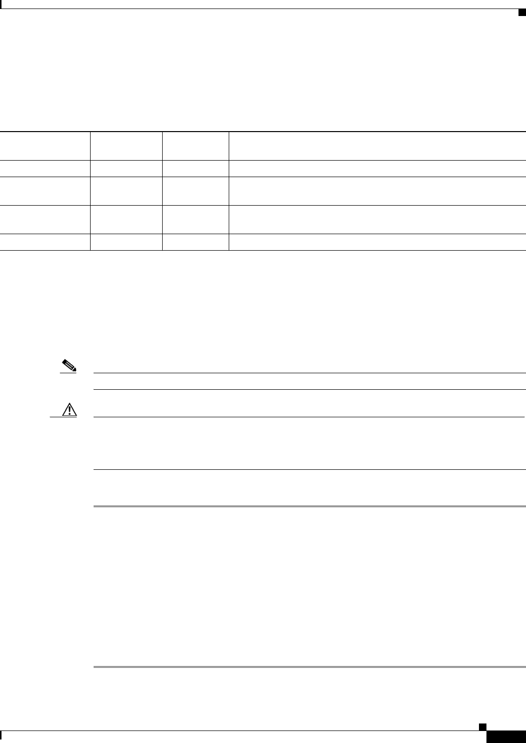
Table 5-16 lists special restrictions for wireless operation in some countries.
Changing Autonomous Access Point Output Power
This section provides instructions for changing the 1250 series autonomous access point output power
to comply with the maximum power limits imposed by special regulatory and country restrictions (see
the“2.4 GHz Band (pre-n IEEE 802.11n)” section on page 5-2, the “5 GHz Band (pre-n IEEE 802.11n)”
section on page 5-7, and the “Special Country Restrictions” section on page 5-17).
Note Administrator privileges may be required in order to change access point settings.
Caution To meet regulatory restrictions, the access point and the external antenna must be professionally
installed. The network administration or other IT professional responsible for installing and configuring the
unit is a suitable professional installer. Following configuration, access to the unit should be password
protected by the network administrator to maintain regulatory compliance.
To change the access point output power level, follow these instructions:
Step 1 Use your web-browser to access your access point.
Step 2 When the Summary Status page displays, click Radio0-802.11G or Radio0-802.11A.
Step 3 On the radio status page, click Settings and the radio settings page displays.
Step 4 For the 802.11G radio, follow these steps:
a. Under CCK Transmit Power (dBm), click the desired output power level.
b. Under OFDM Transmit Power (dBm), click the desired output power level.
Step 5 For the 802.11A radio, under Transmit Power (dBm), click the desired output power level.
Step 6 Scroll down to the bottom of the page and click Apply.
Step 7 Close your web-browser.
Table 5-16 Special Country Restrictions for Wireless Operation
Country
Frequency
Bands (GHz)
Regulatory
Domain Special Limitation and Restrictions
South Korea 2.4 and 5 –E and –K Maximum antenna gain limited to 6 dBi.
Mexico 2.4 –A End user must limit 2.4 GHz operation to 2450 to 2483.5 MHz and
36 dBm EIRP.
Russian Federation 5 –E End user must limit 5 GHz operation to 5150 to 5350 and 5650 to 5725
MHz.
United States 5 –A Indoor use only from 5150-5250 MHz.

CISCO CONFIDENTIAL—DRAFT 1
5-18
Channels and Maximum Power Settings for Cisco Aironet Autonomous Access Points and Bridges
OL-11142-01
Chapter 5 Cisco Aironet 1250 Series Autonomous Access Point
Changing Autonomous Access Point Output Power
CISCO CONFIDENTIAL - Draft AA1
C-1
Cisco Aironet 1250 Series Access Point Hardware Installation Guide
OL-8247-01
APPENDIX
C
Access Point Specifications
Table C-1 lists the technical specifications for the Cisco Aironet 1250 Series Access Point.
Table C-1 Access Point Specifications
Category 2.4 GHz Radio Specifications 5 GHz Radio Specifications
Size 8.1 in W x 9.5 in D x 2.3 in H
20.6 cm W x 24.1 cm D x 5.8 cm H
Weight Base access point (without modules): 2.1 lbs (0.78 kg)
2.4- GHz radio module: 1.4 lbs (0.52 kg)
5-GHz radio module: 1.4 lbs (0.52 kg)
Blank radio module: 1.1 lbs (0.41 kg)
Indicators Three indicators on top of unit: Ethernet traffic, status, and radio traffic.
Connectors Base unit (bottom of access point):
DC power connector (for plug-in power module); RJ-45 connector for 10BASE-T or
100BASE-T or 1000BASE-T Ethernet connections; RJ-45 connector for serial console port
connections.
2.4 GHz radio module (left to right) RP-TNC antenna connectors:
Left (A-Tx/Rx); middle (C-Rx), right (B-Tx/Rx).
5-GHz radio module (left to right):
Left (A-Tx/Rx); middle (C-Rx), right (B-Tx/Rx).
Input voltage 44 to 57 VDC (56 VDC nominal)
Input power 12.95 W (Up to 15.4 W with a 100 m CAT 5E Ethernet cable)—maximum
Operating temperature Access point, DC power module, and power injector:
–4 to 131oF (–20 to 55oC)
Storage temperature -40 to 158oF (-40 to 70oC)
Humidity 10 to 90% non-condensing
Operating altitude 10,000 ft (3048 m) maximum

CISCO CONFIDENTIAL - Draft AA1
C-2
Cisco Aironet 1250 Series Access Point Hardware Installation Guide
OL-8247-01
Appendix C Access Point Specifications
Power output 802.11b 802.11g and 802.11n 802.11n
23 dBm
20 dBm
17 dBm
14 dBm)
11 dBm
8 dBm
5 dBm
2 dBm
-1 dBm
(Depending on the regulatory
domain in which the access
point is installed)
17 dBm
14 dBm
11 dBm
8 dBm
5 dBm
2 dBm
-1 dBm
(Depending on the regulatory
domain in which the access
point is installed)
50 mW (17 dBm)
25 mW (14 dBm)
12 mW (11 dBm)
6 mW (8 dBm)
3 mW (5 dBm)
2 mW (2 dBm)
1 mW (-1 dBm)
(Depending on the regulatory
domain in which the access point
is installed)
Note For the maximum power and the channels allowed in your regulatory domain, refer to the
Channels and Maximum Power Settings for Cisco Aironet Autonomous Access Points and
Bridges or the Channels and Maximum Power Settings for Cisco Aironet Lightweight Access
Points.
Antenna Three external antenna connectors on each radio module.
Frequency 2.400 to 2.497 GHz
(Depending on the regulatory domain in which the access point
is installed)
5.15 to 5.25 GHz
5.25 to 5.35 GHz
5.470 to 5.725 GHz
5.725 to 5.85 GHz
(Depending on the regulatory
domain in which the access point
is installed)
Typical indoor range
(across open office
environment)
105 ft (32 m) @ 54 Mbps
180 ft (55 m) @ 48 Mbps
260 ft (79 m) @ 36 Mbps
285 ft (87 m) @ 24 Mbps
330 ft (100 m) @ 18 Mbps
355 ft (108 m) @ 12 Mbps
365 ft (111 m) @ 11 Mbps
380 ft (116 m) @ 9 Mbps
410 ft (125 m) @ 6 Mbps
425 ft (130 m) @ 5.5 Mbps
445 ft (136 m) @ 2 Mbps
460 ft (140 m) @ 1 Mbps
Note Measured with a 2.2 dBi dipole antenna
85 ft (26 m) @ 54 Mbps
150 ft (46 m) @ 48 Mbps
210 ft (64 m) @ 36 Mbps
230 ft (70 m) @ 24 Mbps
260 ft (79 m) @ 18 Mbps
280 ft (85 m) @ 12 Mbps
310 ft (94 m) @ 9 Mbps
330 ft (100 m) @ 6 Mbps
Note Measured with 3.5 dBi
Omni-directional
antenna
Data Rates (Mbps) 802.11b 802.11g 802.11n 802.11n
1, 2, 5.5, and 11 6, 9, 12, 18,
24, 36, 48, and
54
6.5, 7.22, 13, 13.5, 14.44, 15, 19.5, 21.67, 26, 27,
28.89, 30, 39, 40.5, 43.33, 45, 52, 54, 57.78, 58.5,
60, 65, 72.22, 78, 81, 86.67, 90, 104, 108, 115.56,
117, 120, 121.5, 130, 135, 144.44, 157.5, 162,
180, 216, 180, 216, 240, 243, 270, and 300
Table C-1 Access Point Specifications (continued)
Category 2.4 GHz Radio Specifications 5 GHz Radio Specifications
CISCO CONFIDENTIAL - Draft AA1
C-3
Cisco Aironet 1250 Series Access Point Hardware Installation Guide
OL-8247-01
Appendix C Access Point Specifications
Compliance The 1250 series access point complies with UL 2043 for products installed in a building’s
environmental air handling spaces, such as above suspended ceilings.
Caution The 1250 power injector (AIR-PWRINJ4), the 1250 DC power module (AIR-PWR-SPLY1),
and the antennas should not be placed in a building’s environmental air space, such as
above suspended ceilings.
Safety IEC60950-1
UL60950-1
CAN/CSA C22.2 Number 60950-1-03
EN60950-1
UL 2043
Radio approvals FCC Parts 15.401 -15.407
FCC Part 15.247
FCC Buletin OET-65C
RSS-210
RSS-102
EN 301.893
EN-300.328
AS 4268.2
ARIB-STD-33B
ARIB-STD-66
ARIB STD-T71
EMI and susceptibility FCC Part 15.107 and 15.109 Class B
ICES-003 Class B (Canada)
EN 55022 B
AS/NZS 3548 Class B
VCCI Class B
EN 301.489-1
EN 301.489-17
EN 60601-1-2
RF exposure OET-65C
RSS-102
ANSI C95.1
Table C-1 Access Point Specifications (continued)
Category 2.4 GHz Radio Specifications 5 GHz Radio Specifications

CISCO CONFIDENTIAL - Draft AA1
C-4
Cisco Aironet 1250 Series Access Point Hardware Installation Guide
OL-8247-01
Appendix C Access Point Specifications