Cisco Systems 102068 5.8GHz Radio Module User Manual lwap chpb
Cisco Systems Inc 5.8GHz Radio Module lwap chpb
UserManual.wiki
>
Cisco Systems
>
102068 User Manual
>
Manual lwap 1
Contents
1.
Users Manual 1
2.
Users Manual 2
3.
Users Manual 3
4.
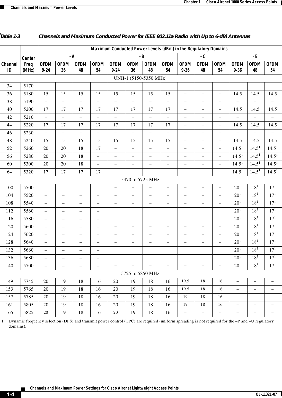
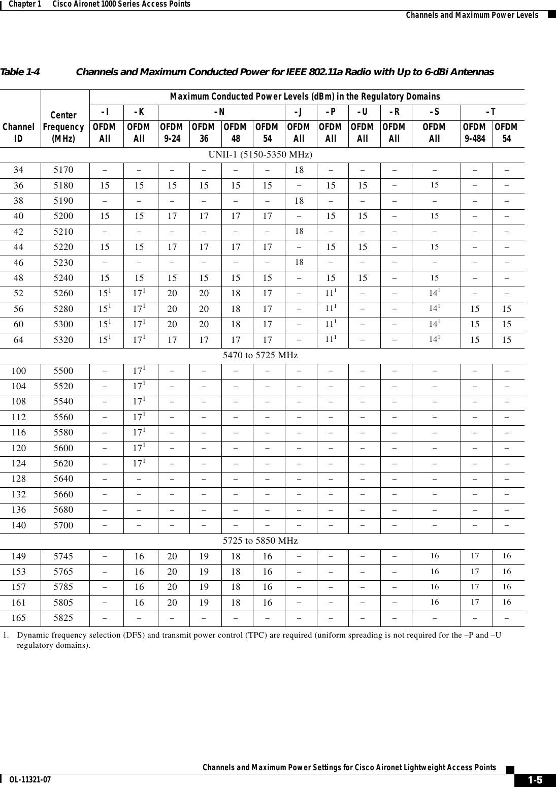
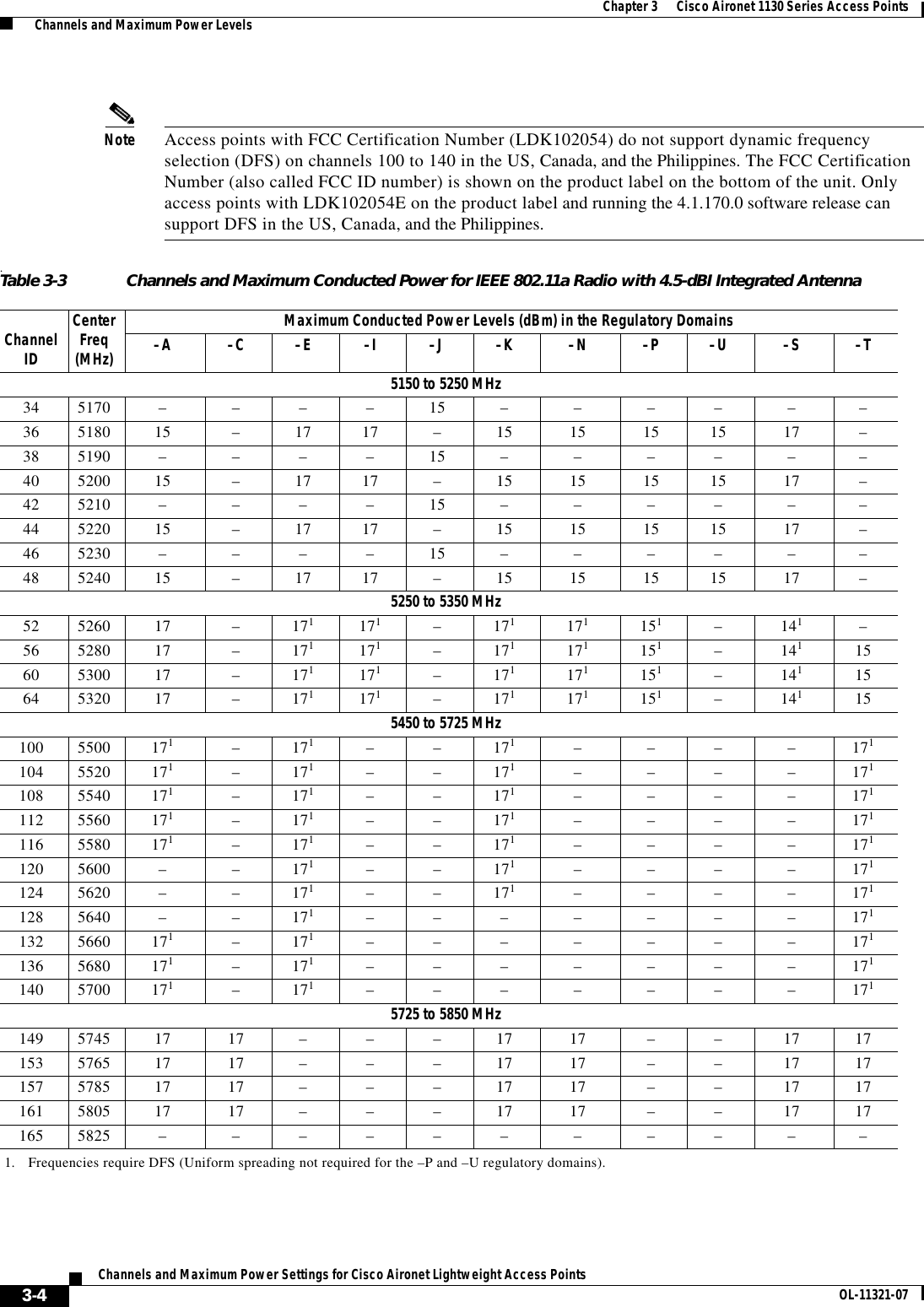
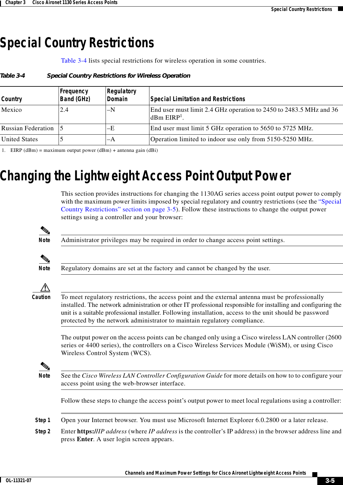
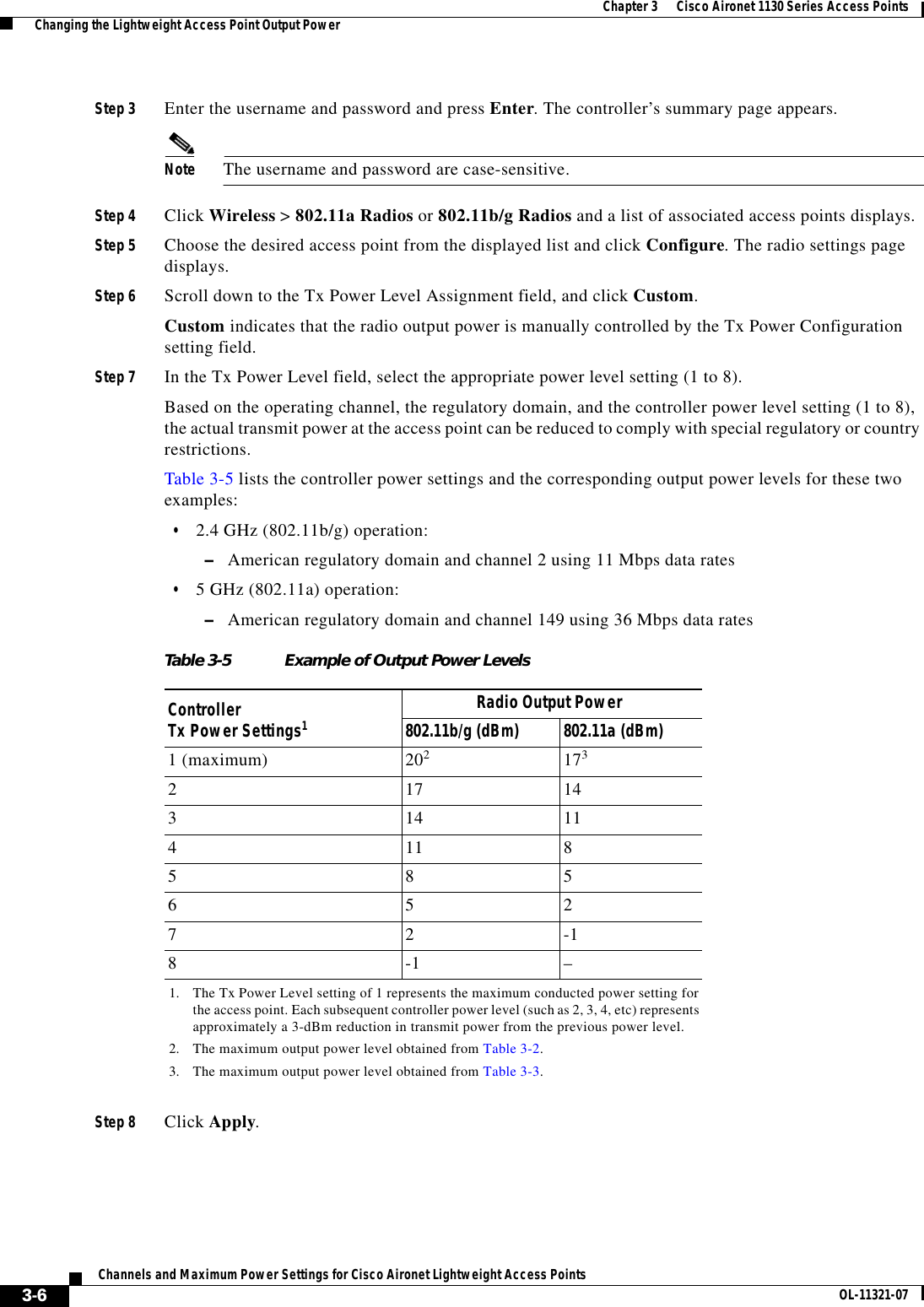
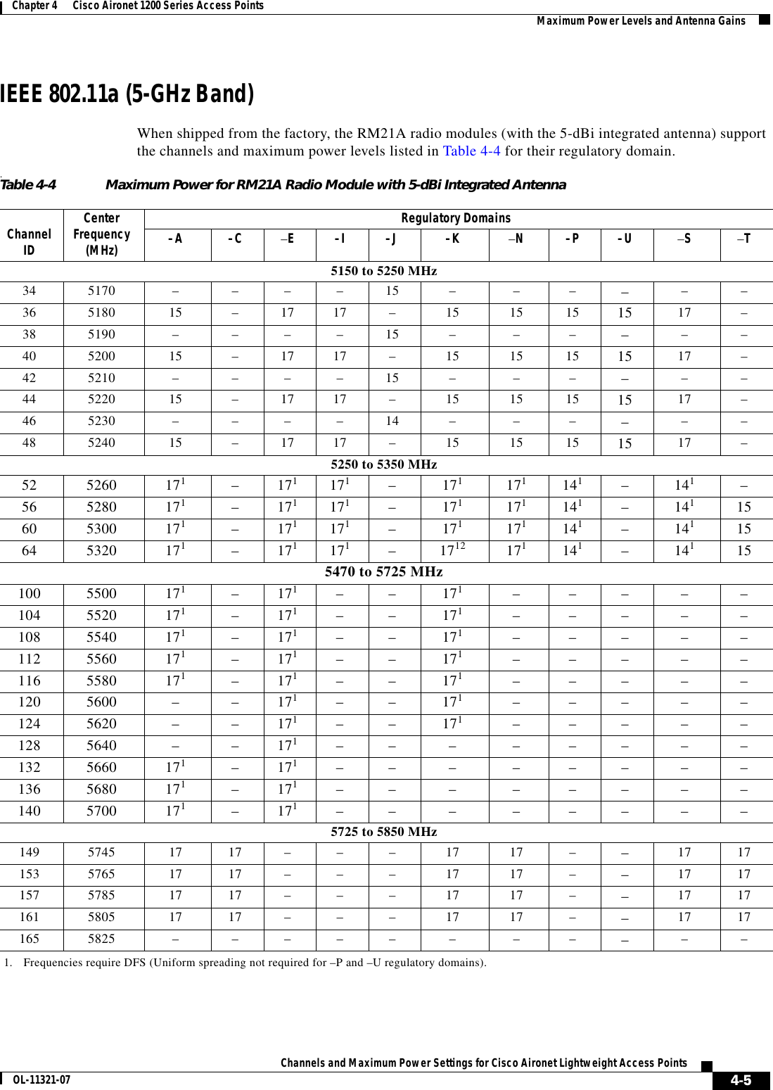
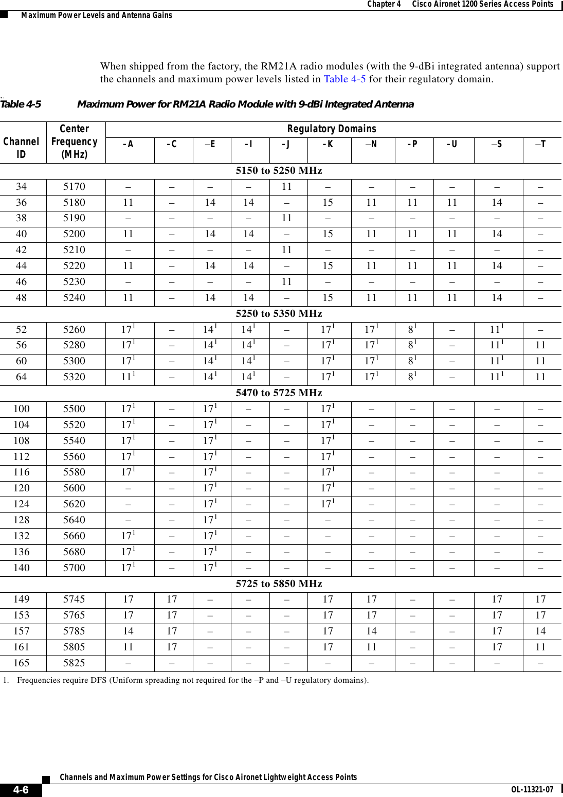
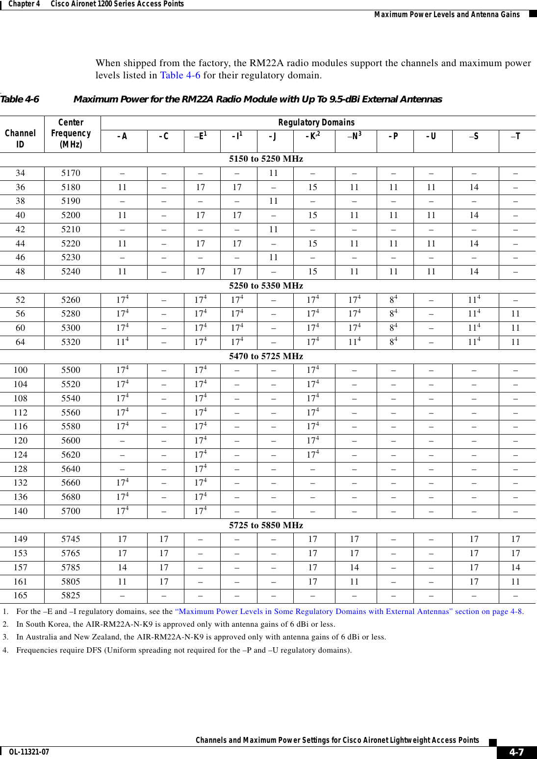
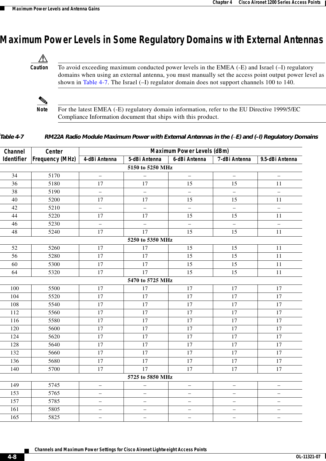
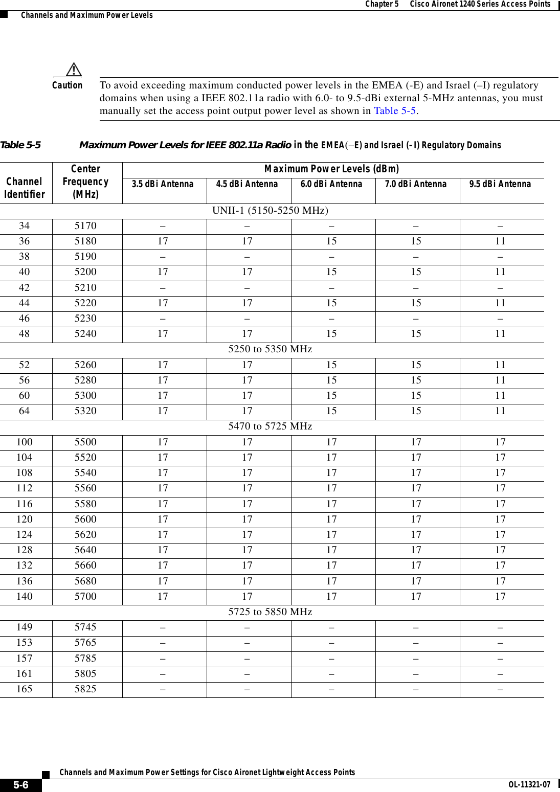
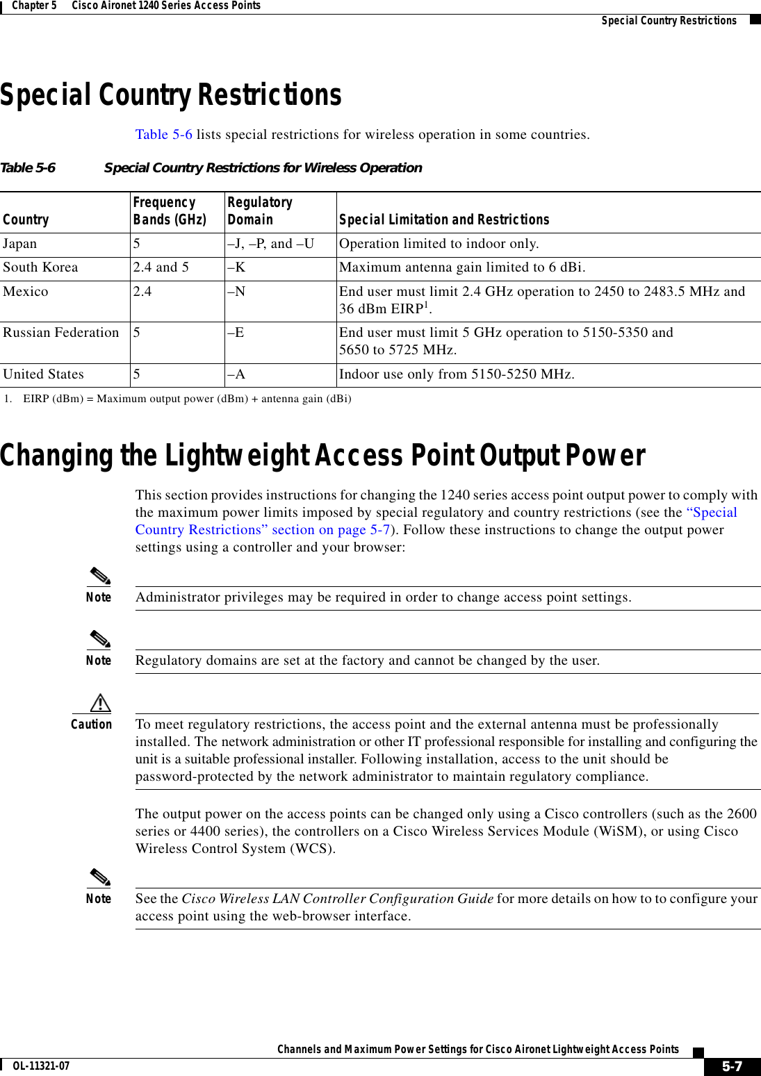
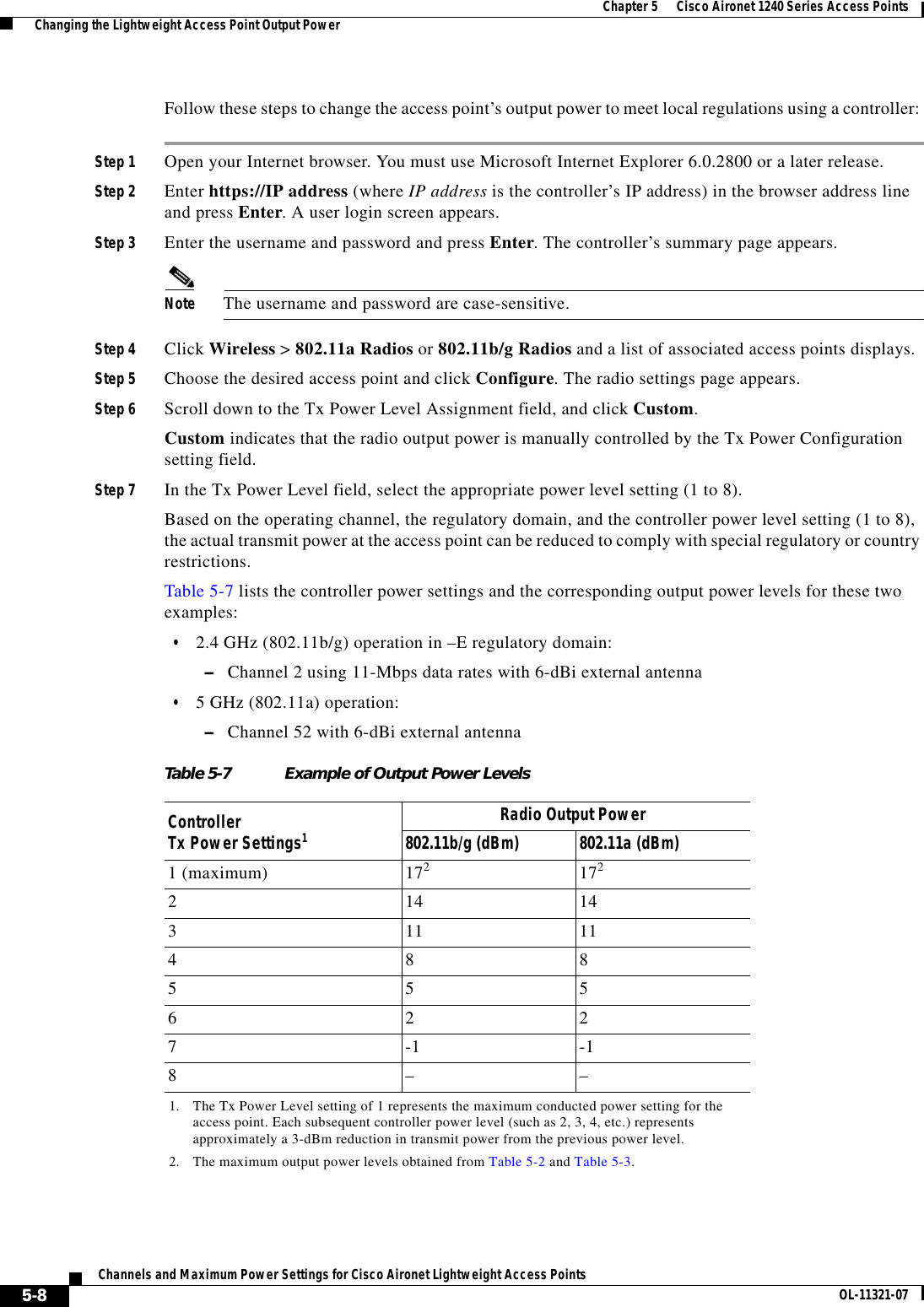
Manual lwap 1
5.
Manual lwap 2
6.
User Manual
Manual lwap 1
Navigation menu
Upload a User Manual
Namespaces
Wiki Guide
HTML
PDF
Info
Views
User Manual
Discussion / Help
Navigation