Cisco Systems 102068 5.8GHz Radio Module User Manual lwap chpb
Cisco Systems Inc 5.8GHz Radio Module lwap chpb
Contents
Manual lwap 2
6-12
Channels and Maximum Power Settings for Cisco Aironet Lightweight Access Points OL-11321-06
Chapter 6 Cisco Aironet 1250 Series Lightweight Access Points
Channels and Maximum Power Levels
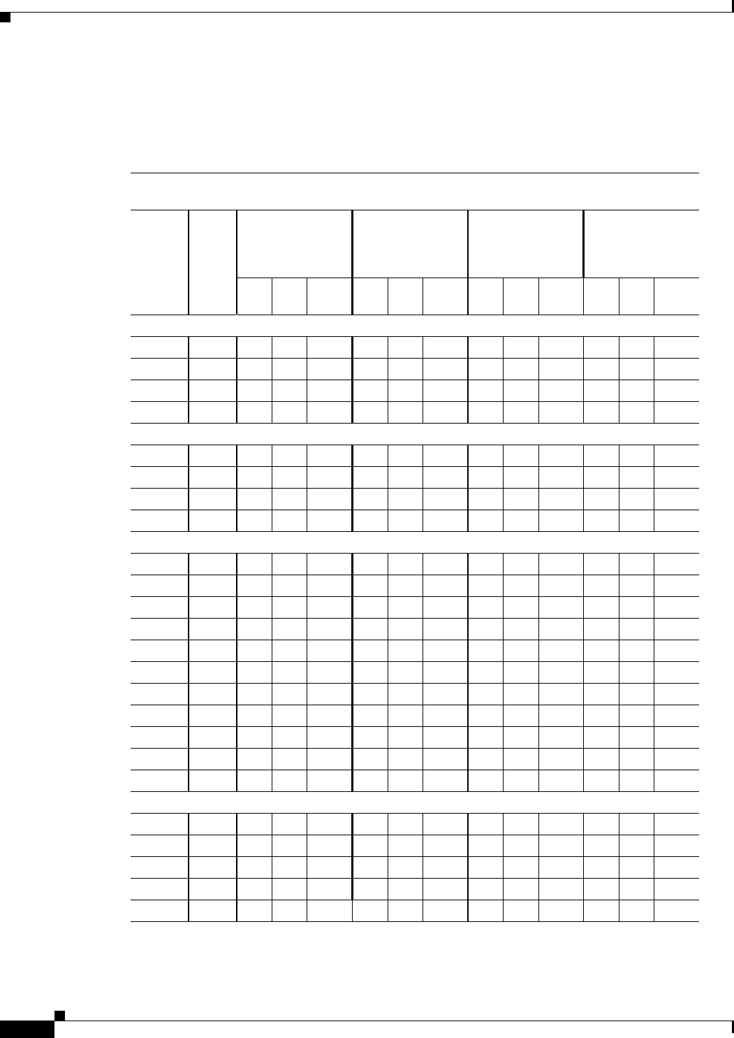
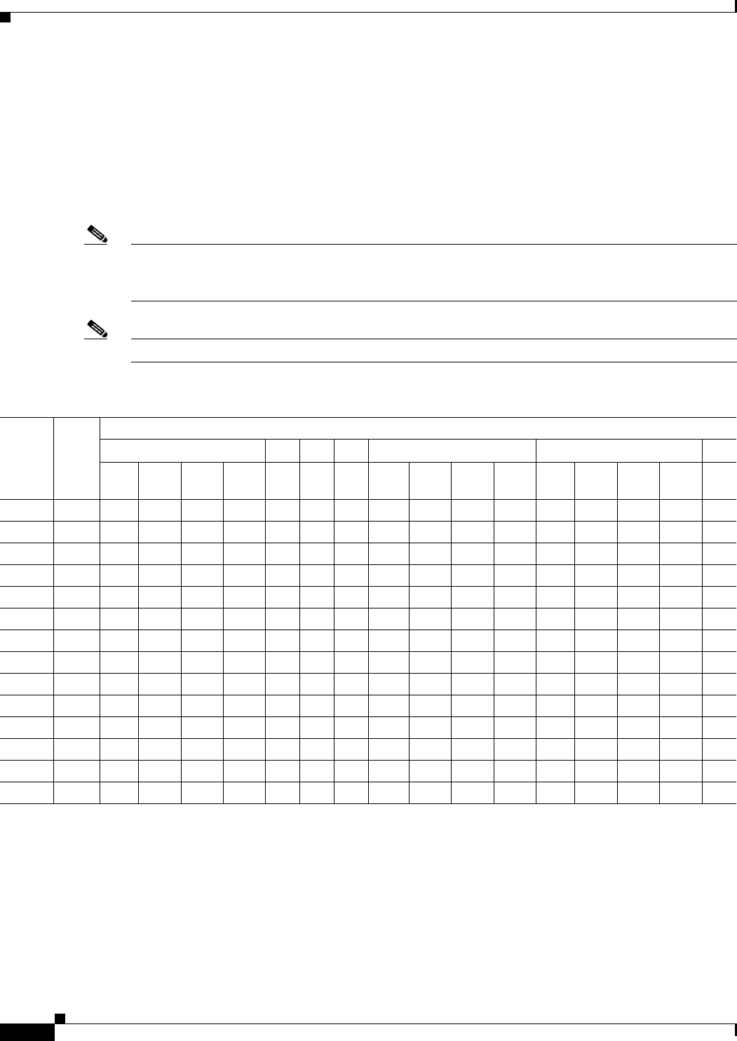
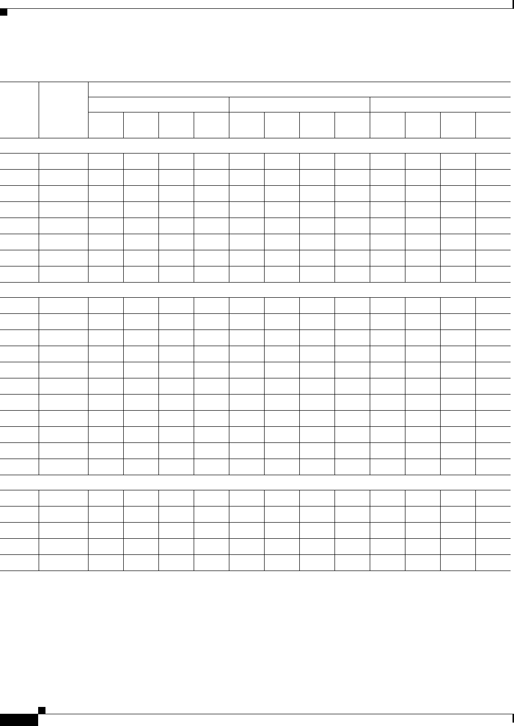
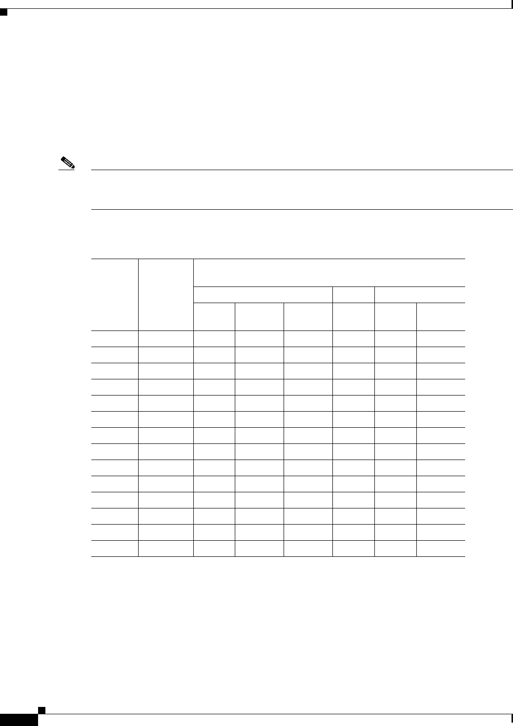
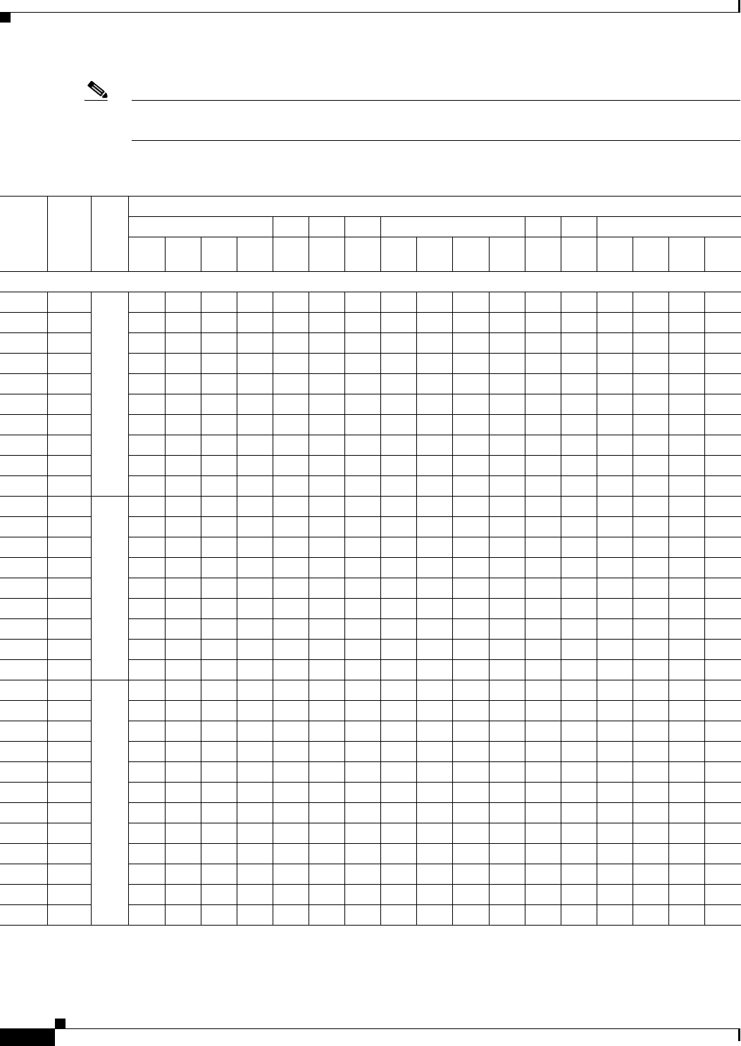
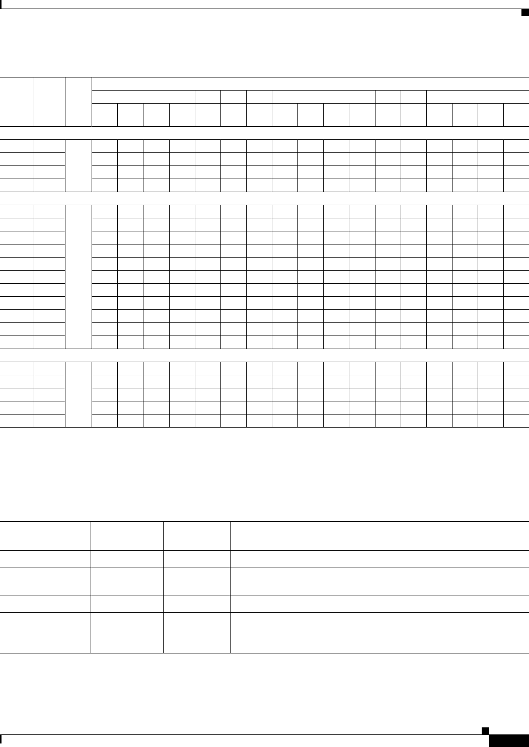
Table 6-11 indicates the channel identifiers, channel center frequencies, and maximum power levels for
each channel allowed by the –K regulatory domain for a 5-GHz radio with up to 6-dBi antennas.
Table 6-11 Channels and Maximum Conducted Power in the –K Regulatory Domain with
up to 6-dBi Antennas
Maximum Conducted Power Levels (dBm) in the –K Regulatory Domain for a 5-GHz Radio with up to 6-dBi
Antennas
Channel
ID Freq
(MHz)
802.11a
Single Antenna
6 to 54 Mbps
HT-20 MHz
Dual Antennas
M0 to M151
1. M0 to M15 corresponds to the Modulaton and Coding Schemes (MCS0 to MCS15). The MCS settings determine the
number of spatial streams, the modulation, the coding rate, and the data rate values.
Duplicate
(2x20 MHz)
Dual Antennas
6 Mbps
HT-40 MHz
Dual Antennas
M0 to M151
Tx
ATx
BTotal
Power Tx
ATx
BTotal
Power Tx
A––Tx
ATx
BTotal
Power
UNII-1 (5150-5250 MHz)
36 5180 14 OFF 14 8 8 11 8 – – 8 8 11
40 5200 14 OFF 14 8 8 11 8 – – 8 8 11
44 5220 14 OFF 14 8 8 11 8 – – 8 8 11
48 5240 14 OFF 14 8 8 11 8 – – 8 8 11
5250 to 5350 MHz
52 5260 17 OFF 17 17 17 20 17 – – 17 17 20
56 5280 17 OFF 17 17 17 20 17 – – 17 17 20
60 5300 17 OFF 17 17 17 20 17 – – 17 17 20
64 5320 17 OFF 17 17 17 20 17 – – 17 17 20
5470 to 5725 MHz
100 5500 17 OFF 17 17 17 20 17 – – 17 17 20
104 5520 17 OFF 17 17 17 20 17 – – 17 17 20
108 5540 17 OFF 17 17 17 20 17 – – 17 17 20
112 5560 17 OFF 17 17 17 20 17 – – 17 17 20
116 5580 17 OFF 17 17 17 20 17 – – 17 17 20
120 5600 17 OFF 17 17 17 20 17 – – 17 17 20
124 5620 17 OFF 17 17 17 20 17 – – – – –
128 5640 – – – – – – – – – – – –
132 5660 – – – – – – – – – – – –
136 5680 – – – – – – – – – – – –
140 5700 – – – – – – – – – – – –
5725 to 5850 MHz
149 5745 17 OFF 17 17 17 20 17 – – 17 17 20
153 5765 17 OFF 17 17 17 20 17 – – 17 17 20
157 5785 17 OFF 17 17 17 20 17 – – 17 17 20
161 5805 17 OFF 17 17 17 20 17 – – 17 17 20
165 5825 – – – – – – – – – – – –
6-13
Channels and Maximum Power Settings for Cisco Aironet Lightweight Access Points
OL-11321-06
Chapter 6 Cisco Aironet 1250 Series Lightweight Access Points Channels and Maximum Power Levels
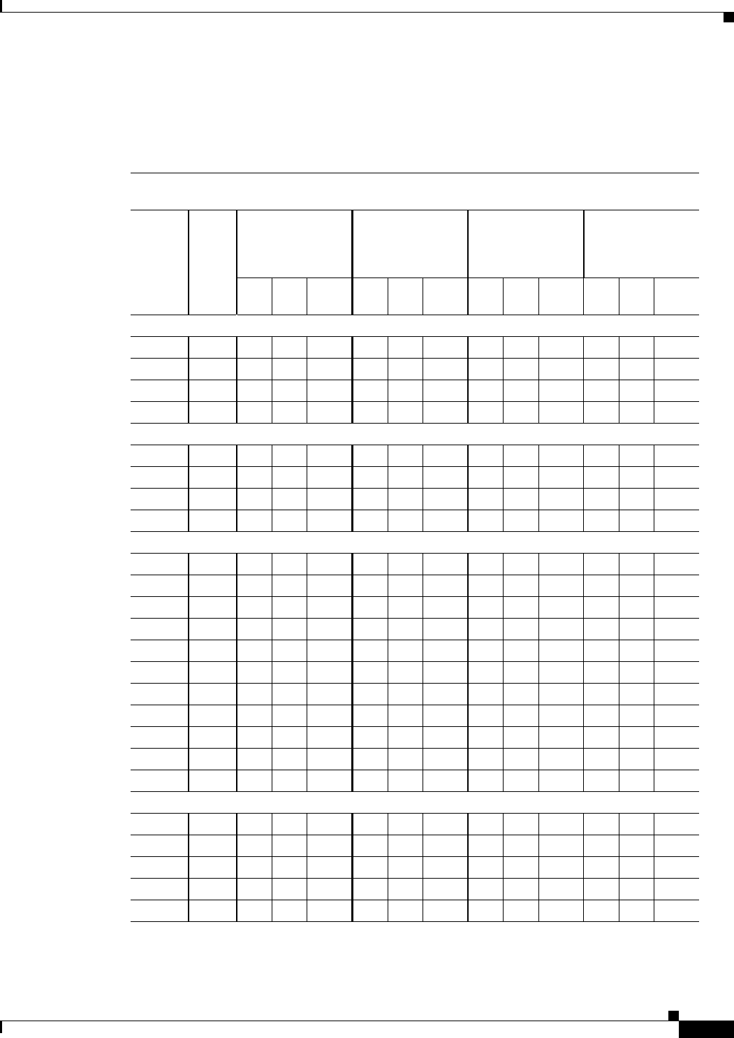
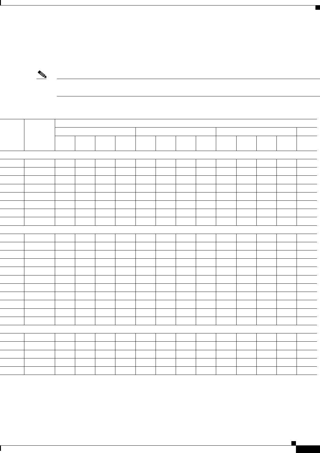
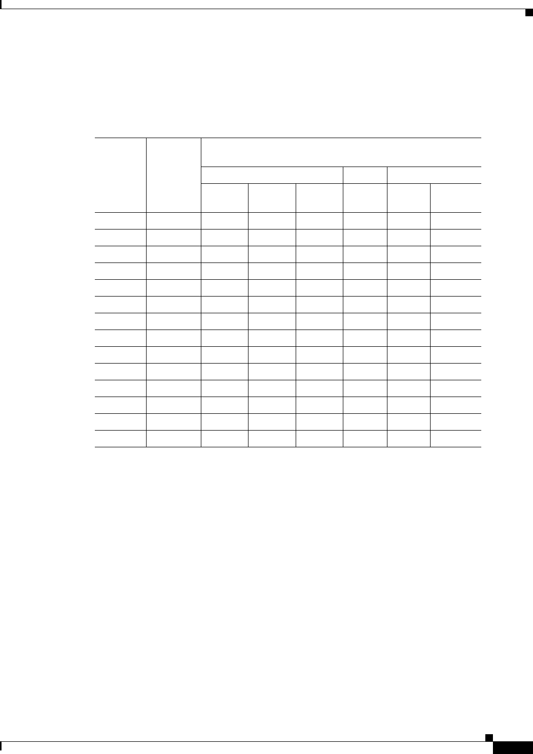
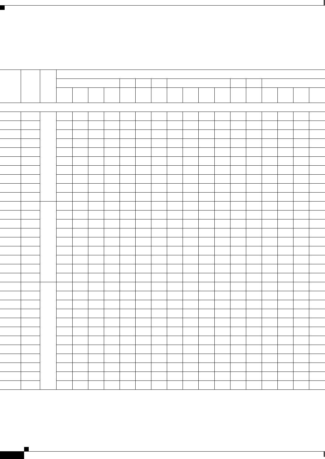
Table 6-12 indicates the channel identifiers, channel center frequencies, and maximum power levels for
each channel allowed by the –N regulatory domain for a 5-GHz radio with up to 6-dBi antennas.
Table 6-12 Channels and Maximum Conducted Power in the –N Regulatory Domain with
up to 6-dBi Antennas
Maximum Conducted Power Levels (dBm) in the –N Regulatory Domain for a 5-GHz Radio with
up to 6-dBi Antennas
Channel
ID Freq
(MHz)
802.11a
Single Antenna
6 to 54 Mbps
HT-20 MHz
Dual Antennas
M0 to M151
1. M0 to M15 corresponds to the Modulaton and Coding Schemes (MCS0 to MCS15). The MCS settings determine the
number of spatial streams, the modulation, the coding rate, and the data rate values.
Duplicate
(2x20 MHz)
Dual Antennas
6 Mbps
HT-40 MHz
Dual Antennas
M0 to M151
Tx
ATx
BTotal
Power Tx
ATx
BTotal
Power Tx
A––Tx
ATx
BTotal
Power
UNII-1 (5150-5250 MHz)
36 5180 14 OFF 14 11 11 14 11 – – 11 11 14
40 5200 14 OFF 14 11 11 14 11 – – 11 11 14
44 5220 14 OFF 14 11 11 14 11 – – 11 11 14
48 5240 14 OFF 14 11 11 14 11 – – 11 11 14
5250 to 5350 MHz
52 5260 17 OFF 17 14 14 17 14 – – 14 14 17
56 5280 17 OFF 17 14 14 17 14 – – 14 14 17
60 5300 17 OFF 17 14 14 17 11 – – 11 11 14
64 5320 11 OFF 11 14 14 17 11 – – 11 11 14
5470 to 5725 MHz
100 5500 ––––––––––––
104 5520 ––––––––––––
108 5540 ––––––––––––
112 5560 ––––––––––––
116 5580 ––––––––––––
120 5600 ––––––––––––
124 5620 ––––––––––––
128 5640 ––––––––––––
132 5660 ––––––––––––
136 5680 ––––––––––––
140 5700 ––––––––––––
5725 to 5850 MHz
149 5745 17 OFF 17 17 17 20 17 – – 17 17 20
153 5765 17 OFF 17 17 17 20 17 – – 17 17 20
157 5785 17 OFF 17 17 17 20 17 – – 17 17 20
161 5805 17 OFF 17 17 17 20 17 – – 17 17 20
165 5825 17 OFF 17 17 17 20 – – – – – –
6-14
Channels and Maximum Power Settings for Cisco Aironet Lightweight Access Points OL-11321-06
Chapter 6 Cisco Aironet 1250 Series Lightweight Access Points
Channels and Maximum Power Levels
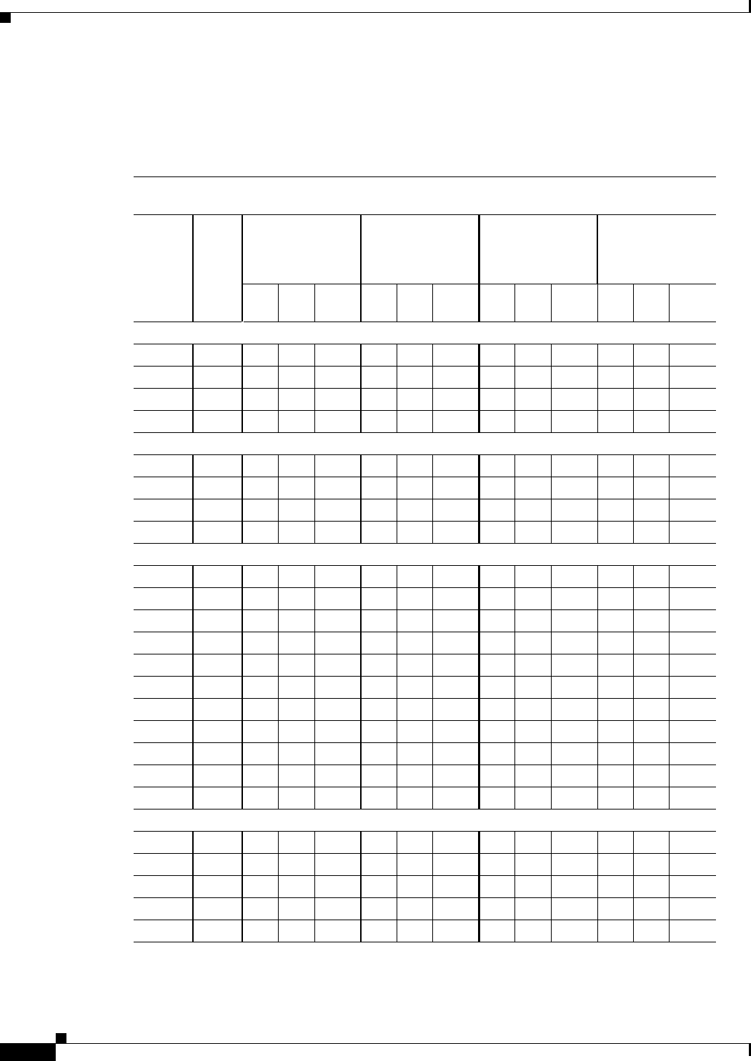
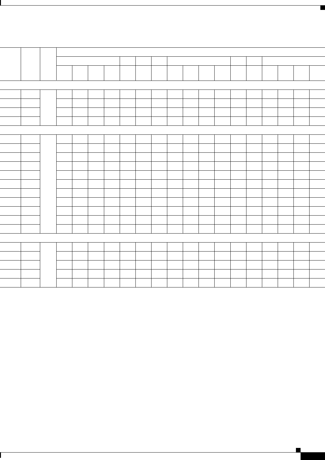
Table 6-13 indicates the channel identifiers, channel center frequencies, and maximum power levels for
each channel allowed by the –P regulatory domain for a 5-GHz radio with up to 6-dBi antennas.
Table 6-13 Channels and Maximum Conducted Power in the –P Regulatory Domain with up to
6-dBi Antennas
Maximum Conducted Power Levels (dBm) in the –P Regulatory Domain for the 5-GHz Radio with up to 6-dBi
Antennas
Channel
ID Freq
(MHz)
802.11a
Single Antenna
6 to 54 Mbps
HT-20 MHz
Dual Antennas
M0 to M151
1. M0 to M15 corresponds to the Modulaton and Coding Schemes (MCS0 to MCS15). The MCS settings determine the
number of spatial streams, the modulation, the coding rate, and the data rate values.
Duplicate
(2x20 MHz)
Dual Antennas
6 Mbps
HT-40 MHz
Dual Antennas
M0 to M151
Tx
ATx
BTotal
Power Tx
ATx
BTotal
Power Tx
A––Tx
ATx
BTotal
Power
UNII-1 (5150-5250 MHz)
36 5180 14 OFF 14 11 11 14 11 – – 11 11 14
40 5200 14 OFF 14 11 11 14 11 – – 11 11 14
44 5220 14 OFF 14 11 11 14 11 – – 11 11 14
48 5240 14 OFF 14 11 11 14 11 – – 11 11 14
5250 to 5350 MHz
52 5260 14 OFF 14 11 11 14 11 – – 11 11 14
56 5280 14 OFF 14 11 11 14 11 – – 11 11 14
60 5300 14 OFF 14 11 11 14 11 – – 11 11 14
64 5320 14 OFF 14 11 11 14 11 – – 11 11 14
5470 to 5725 MHz
100 5500 – – – – – – – – – – – –
104 5520 – – – – – – – – – – – –
108 5540 – – – – – – – – – – – –
112 5560 – – – – – – – – – – – –
116 5580 – – – – – – – – – – – –
120 5600 – – – – – – – – – – – –
124 5620 – – – – – – – – – – – –
128 5640 – – – – – – – – – – – –
132 5660 – – – – – – – – – – – –
136 5680 – – – – – – – – – – – –
140 5700 – – – – – – – – – – – –
5725 to 5850 MHz
149 5745 – – – – – – – – – – – –
153 5765 – – – – – – – – – – – –
157 5785 – – – – – – – – – – – –
161 5805 – – – – – – – – – – – –
165 5825 – – – – – – – – – – – –

6-15
Channels and Maximum Power Settings for Cisco Aironet Lightweight Access Points
OL-11321-06
Chapter 6 Cisco Aironet 1250 Series Lightweight Access Points Channels and Maximum Power Levels
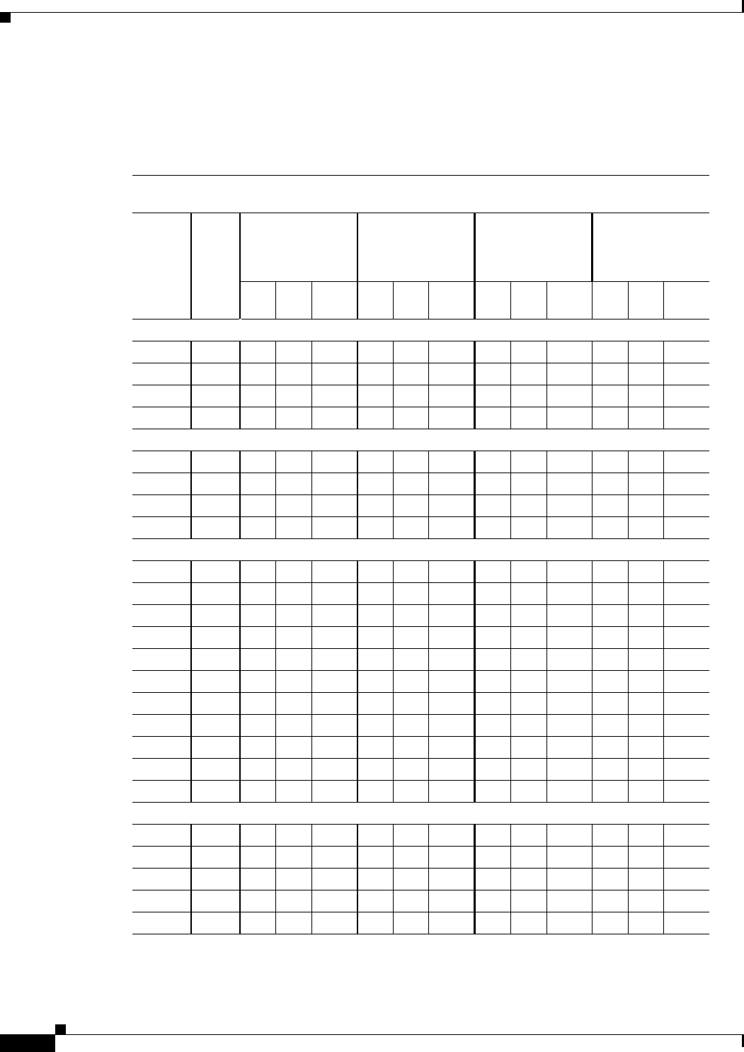
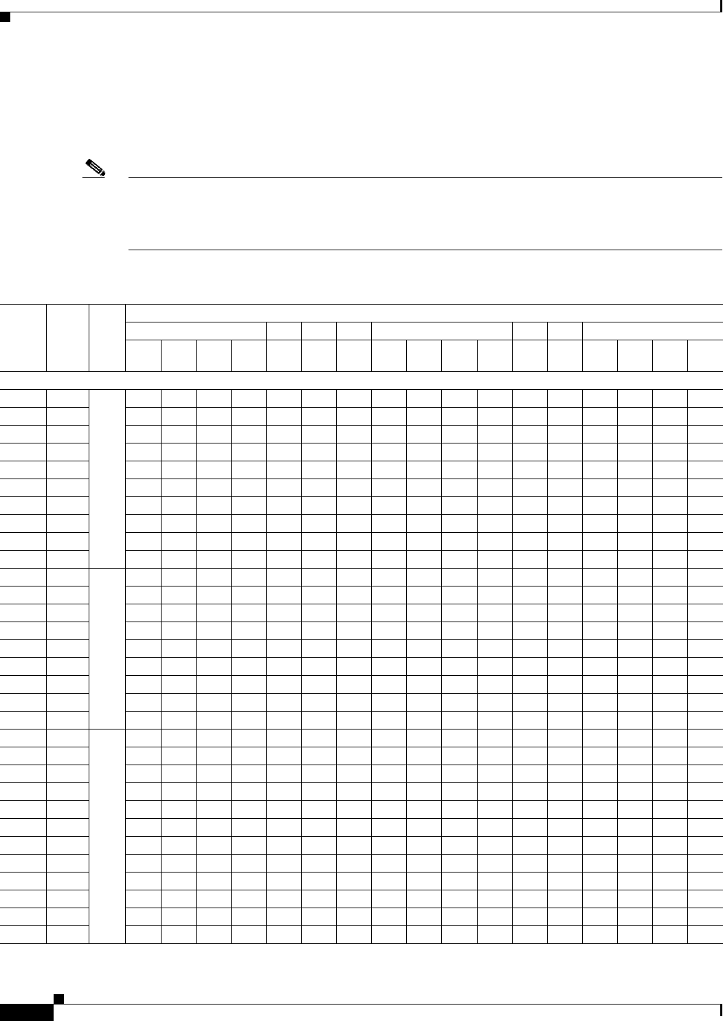
Table 6-14 indicates the channel identifiers, channel center frequencies, and maximum power levels for
each channel allowed by the –S regulatory domain for a 5-GHz radio with up to 6-dBi antennas.
Table 6-14 Channels and Maximum Conducted Power in the –S Regulatory Domain with
up to 6-dBi Antennas
Maximum Conducted Power Levels (dBm) in the –S Regulatory Domain for a 5-GHz Radio with
up to 6-dBi Antennas
Channel
ID Freq
(MHz)
802.11a
Single Antenna
6 to 54 Mbps
HT-20 MHz
Dual Antennas
M0 to M151
1. M0 to M15 corresponds to the Modulaton and Coding Schemes (MCS0 to MCS15). The MCS settings determine the
number of spatial streams, the modulation, the coding rate, and the data rate values.
Duplicate
(2x20 MHz)
Dual Antennas
6 Mbps
HT-40 MHz
Dual Antennas
M0 to M151
Tx
ATx
BTotal
Power Tx
ATx
BTotal
Power Tx
A––Tx
ATx
BTotal
Power
UNII-1 (5150-5250 MHz)
36 5180 17 OFF 17 14 14 17 14 – – 14 14 17
40 5200 17 OFF 17 14 14 17 14 – – 14 14 17
44 5220 17 OFF 17 14 14 17 14 – – 14 14 17
48 5240 17 OFF 17 14 14 17 14 – – 14 14 17
5250 to 5350 MHz
52 5260 17 OFF 17 14 14 17 14 – – 14 14 17
56 5280 17 OFF 17 14 14 17 14 – – 14 14 17
60 5300 17 OFF 17 14 14 17 14 – – 14 14 17
64 5320 17 OFF 17 14 14 17 14 – – 14 14 17
5470 to 5725 MHz
100 5500 ––––––––––––
104 5520 ––––––––––––
108 5540 ––––––––––––
112 5560 ––––––––––––
116 5580 ––––––––––––
120 5600 ––––––––––––
124 5620 ––––––––––––
128 5640 ––––––––––––
132 5660 ––––––––––––
136 5680 ––––––––––––
140 5700 ––––––––––––
5725 to 5850 MHz
149 5745 17 OFF 17 17 17 20 17 – – 17 17 20
153 5765 17 OFF 17 17 17 20 17 – – 17 17 20
157 5785 17 OFF 17 17 17 20 17 – – 17 17 20
161 5805 17 OFF 17 17 17 20 17 – – 17 17 20
165 5825 17 OFF 17 17 17 20 – – – – – –
6-16
Channels and Maximum Power Settings for Cisco Aironet Lightweight Access Points OL-11321-06
Chapter 6 Cisco Aironet 1250 Series Lightweight Access Points
Channels and Maximum Power Levels
Table 6-7 indicates the channel identifiers, channel center frequencies, and maximum power levels for
each channel allowed by the –T regulatory domain for a 5-GHz radio with up to 6-dBi antennas.
Table 6-15 Channels and Maximum Conducted Power in the –T Regulatory Domain with
up to 6-dBi Antennas
Maximum Conducted Power Levels (dBm) in the –T Regulatory Domain for a 5-GHz Radio with
up to 6-dBi Antennas
Channel
ID Freq
(MHz)
802.11a
Single Antenna
6 to 54 Mbps
HT-20 MHz
Dual Antennas
M0 to M151
1. M0 to M15 corresponds to the Modulaton and Coding Schemes (MCS0 to MCS15). The MCS settings determine the
number of spatial streams, the modulation, the coding rate, and the data rate values.
Duplicate
(2x20 MHz)
Dual Antennas
6 Mbps
HT-40 MHz
Dual Antennas
M0 to M151
Tx
ATx
BTotal
Power Tx
ATx
BTotal
Power Tx
A––Tx
ATx
BTotal
Power
UNII-1 (5150-5250 MHz)
36 5180 – – – – – – – – – – – –
40 5200 – – – – – – – – – – – –
44 5220 – – – – – – – – – – – –
48 5240 – – – – – – – – – – – –
5250 to 5350 MHz
52 5260 – – – – – – – – – – – –
56 5280 14 OFF 14 11 11 14 – – – – – –
60 5300 14 OFF 14 11 11 14 8 – – 11 11 14
64 5320 14 OFF 14 11 11 14 8 – – 11 11 14
5470 to 5725 MHz
100 5500 17 OFF 17 17 17 20 14 – – 17 17 20
104 5520 17 OFF 17 17 17 20 14 – – 17 17 20
108 5540 17 OFF 17 17 17 20 14 – – 17 17 20
112 5560 17 OFF 17 17 17 20 14 – – 17 17 20
116 5580 17 OFF 17 17 17 20 14 – – 17 17 20
120 5600 17 OFF 17 17 17 20 14 – – 17 17 20
124 5620 17 OFF 17 17 17 20 14 – – 17 17 20
128 5640 17 OFF 17 17 17 20 14 – – 17 17 20
132 5660 17 OFF 17 17 17 20 14 – – 17 17 20
136 5680 17 OFF 17 17 17 20 14 – – 17 17 20
140 5700 17 OFF 17 17 17 20 – – – – – –
5725 to 5850 MHz
149 5745 17 OFF 17 17 17 20 17 – – 17 17 20
153 5765 17 OFF 17 17 17 20 17 – – 17 17 20
157 5785 17 OFF 17 17 17 20 17 – – 17 17 20
161 5805 17 OFF 17 17 17 20 17 – – 17 17 20
165 5825 17 OFF 17 17 17 20 – – – – – –
6-17
Channels and Maximum Power Settings for Cisco Aironet Lightweight Access Points
OL-11321-06
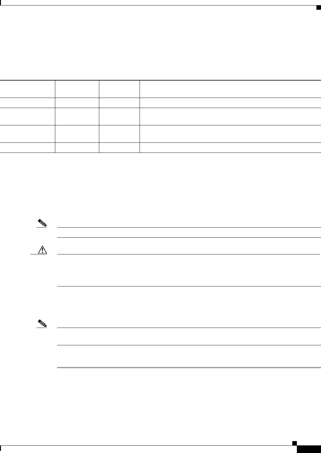
Chapter 6 Cisco Aironet 1250 Series Lightweight Access Points Special Country Restrictions
Special Country Restrictions
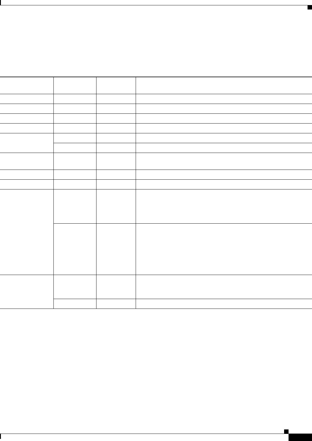
Table 6-16 lists special restrictions for wireless operation in some countries.
Changing Lightweight Access Point Output Power
This section provides instructions for changing the 1250 series access point output power to comply with
the maximum power limits imposed by special regulatory and country restrictions (see the “Special
Country Restrictions” section on page 6-17). Follow these instructions to change the output power
settings using a controller and your browser:
Note Administrator privileges may be required in order to change access point settings.
Caution To meet regulatory restrictions, the access point and the external antenna must be professionally
installed. The network administration or other IT professional responsible for installing and configuring the
unit is a suitable professional installer. Following installation, access to the unit should be
password-protected by the network administrator to maintain regulatory compliance.
The output power on the access points can be changed only using a Cisco wireless LAN controller
(2600 series or 4400 series), the controllers on a Cisco Wireless Services Module (WiSM), or using
Cisco Wireless Control System (WCS).
Note See the Cisco Wireless LAN Controller Configuration Guide for more details on how to to configure your
access point using the web-browser interface.
Follow these steps to change the access point’s output power to meet local regulations using a controller:
Step 1 Open your Internet browser. You must use Microsoft Internet Explorer 6.0.2800 or a later release.
Step 2 Enter https://IP address (where IP address is the controller’s IP address) in the browser address line
and press Enter. A user login screen appears.
Table 6-16 Special Country Restrictions for Wireless Operation
Country Frequency
Bands (GHz) Regulatory
Domain Special Limitation and Restrictions
South Korea 2.4 and 5 –E and –K Maximum antenna gain limited to 6 dBi.
Mexico 2.4 –A End user must limit 2.4 GHz operation to 2450 to 2483.5 MHz and
36 dBm EIRP.
Russian Federation 5–E End user must limit 5 GHz operation to 5150 to 5350 and 5650 to 5725
MHz.
United States 5 –A Indoor use only from 5150-5250 MHz.
6-18
Channels and Maximum Power Settings for Cisco Aironet Lightweight Access Points OL-11321-06
Chapter 6 Cisco Aironet 1250 Series Lightweight Access Points
Changing Lightweight Access Point Output Power
Step 3 Enter the username and password and press Enter. The controller’s summary page appears.
Note The username and password are case-sensitive.
Step 4 Click Wireless > 802.11a/n Radios or 802.11b/g/n Radios and a list of associated access points
appears.
Step 5 Choose the desired access point and click Configure. The radio settings page appears.
Step 6 Scroll down to the Tx Power Level Assignment field, and click Custom.
Custom indicates that the radio output power is manually controlled by the Tx Power Configuration
setting field.
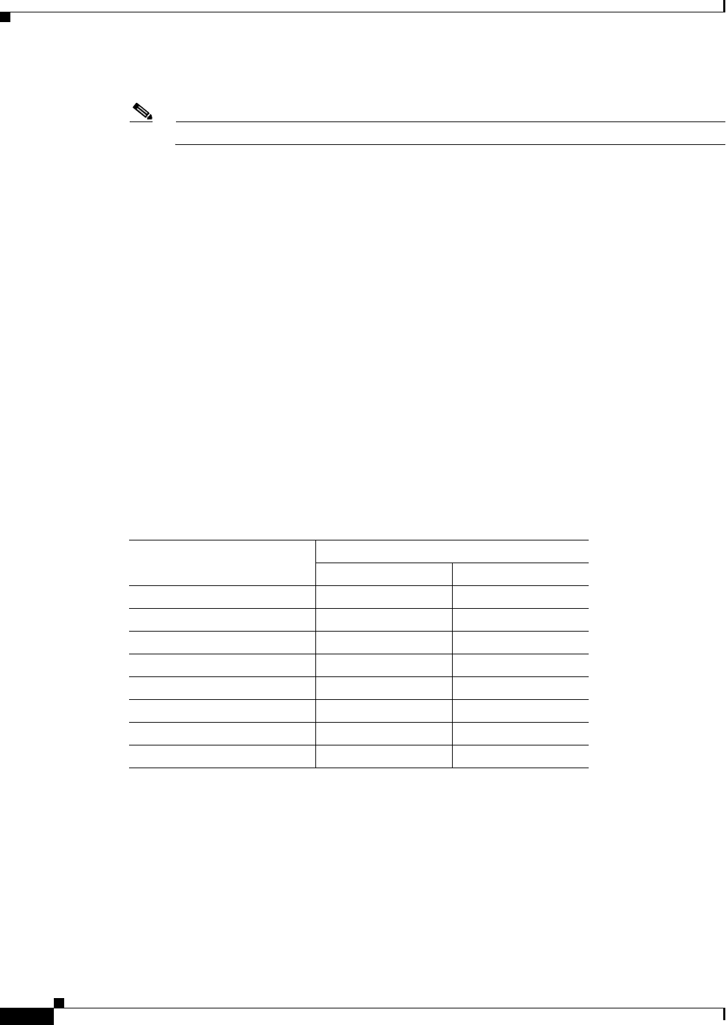
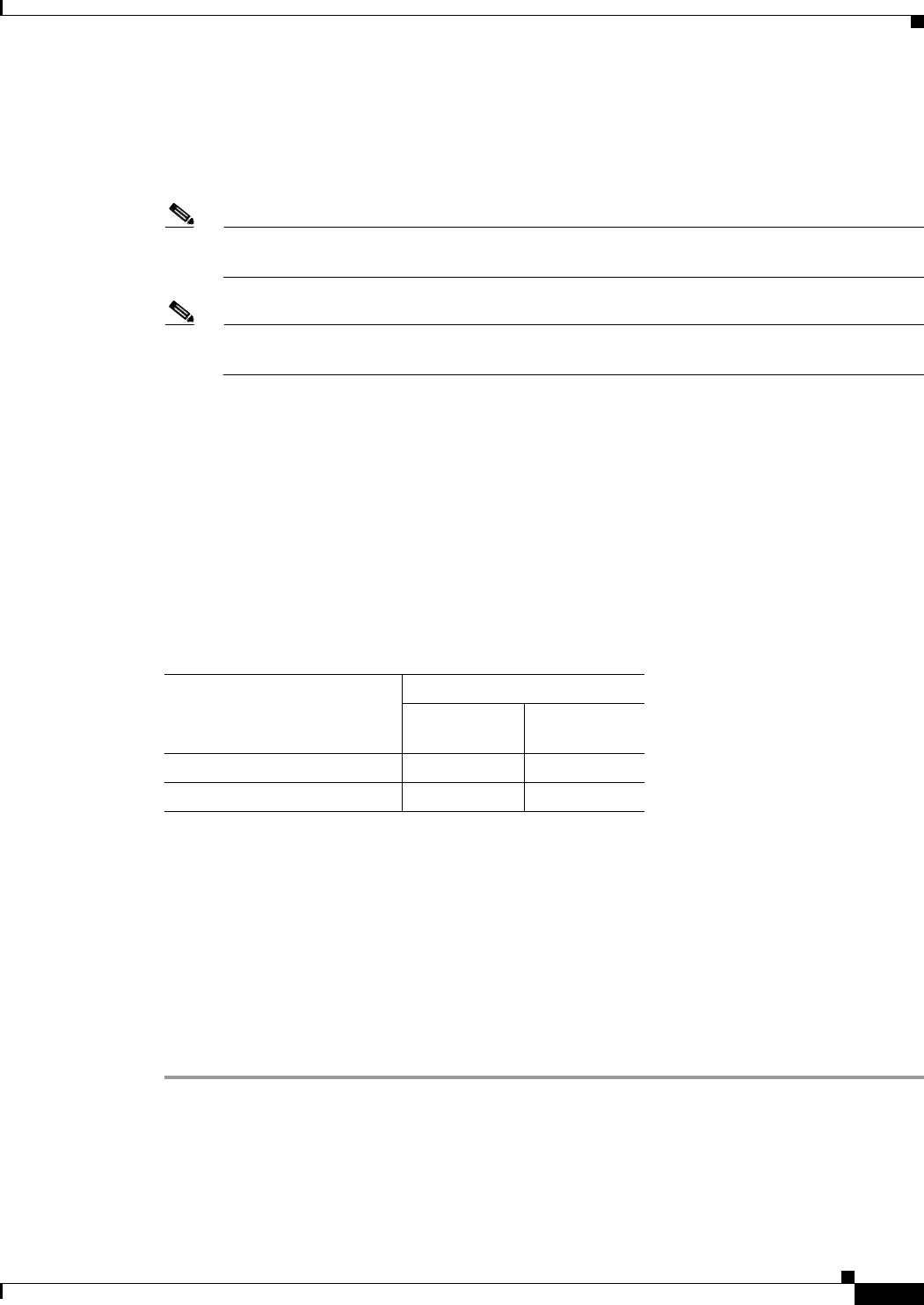
Step 7 In the Tx Power Level field, select the appropriate power level setting (1 to 8).
Based on the operating channel, the regulatory domain, and the controller power level setting (1 to 8),
the actual transmit power at the access point can be reduced to comply with special regulatory or country
restrictions.
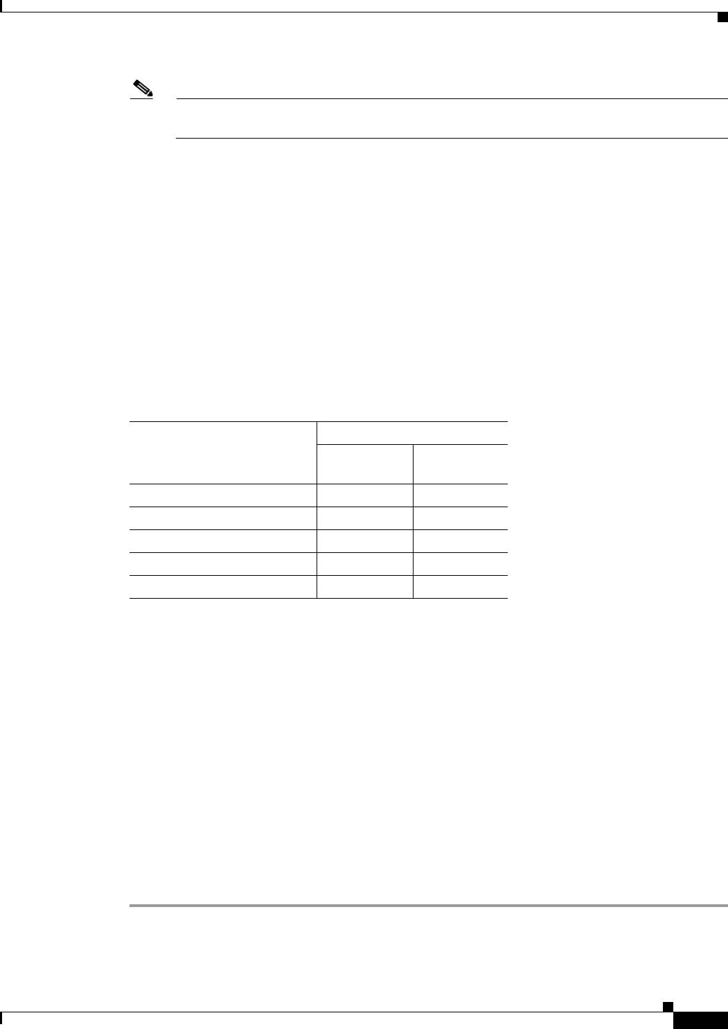
Table 17 lists the controller power settings and the corresponding output power levels for these two
examples:
• 2.4 GHz ) operation in EMEA (–E) regulatory domain:
–
Channel 2 using 11-Mbps data rates with 6-dBi external antenna
• 5 GHz (802.11a) operation:
–
Channel 52 with 6-dBi external antenna
• For 802.11b/g/n (see Table 6-3 and Table 17), the manual controller Tx Power Level setting is 2.
• For 802.11a/n (see Table 6-4 and Table 17), the manual controller Tx Power Level setting is 2.
Step 8 Click Apply.
Table 17 Example of Output Power Levels
Controller
Tx Power Settings1
1. The Tx Power Level setting of 1 represents the maximum conducted power setting for the
access point. Each subsequent controller power level (such as 2, 3, 4, etc.) represents
approximately a 3-dBm reduction in transmit power from the previous power level.
Radio Output Power
802.11b/g/n (dBm) 802.11a/n (dBm)
1 (maximum) 172
2. The maximum output power levels obtained from Table 6-1 and Table 6-2.
172
214 14
311 11
4 8 8
5 5 5
6 2 2
7-1 -1
8 – –

6-19
Channels and Maximum Power Settings for Cisco Aironet Lightweight Access Points
OL-11321-06
Chapter 6 Cisco Aironet 1250 Series Lightweight Access Points Changing Lightweight Access Point Output Power
Step 9 Close your Internet browser.

6-20
Channels and Maximum Power Settings for Cisco Aironet Lightweight Access Points OL-11321-06
Chapter 6 Cisco Aironet 1250 Series Lightweight Access Points
Changing Lightweight Access Point Output Power

CHAPTER
7-1
Channels and Maximum Power Settings for Cisco Aironet Lightweight Access Points
OL-11321-07
7
Cisco Aironet 1300 Series Access Points
This chapter lists the lightweight access point (model: AIR-LAP1310G) IEEE 802.11b/g 2.4-GHz
channels, maximum power levels, and antenna gains supported by the world’s regulatory domains. For
additional product hardware information refer to the Cisco Aironet 1300 Series Outdoor Access
Point/Bridge Hardware Installation Guide.
The following topics are covered in this chapter:
• Channels, page 7-2
• Maximum Power Levels and Antenna Gains, page 7-3
• Changing the Lightweight Access Point Output Power, page 7-4
• Power Conversion Table, page 7-6
7-2
Channels and Maximum Power Settings for Cisco Aironet Lightweight Access Points OL-11321-07
Chapter 7 Cisco Aironet 1300 Series Access Points
Channels
Channels
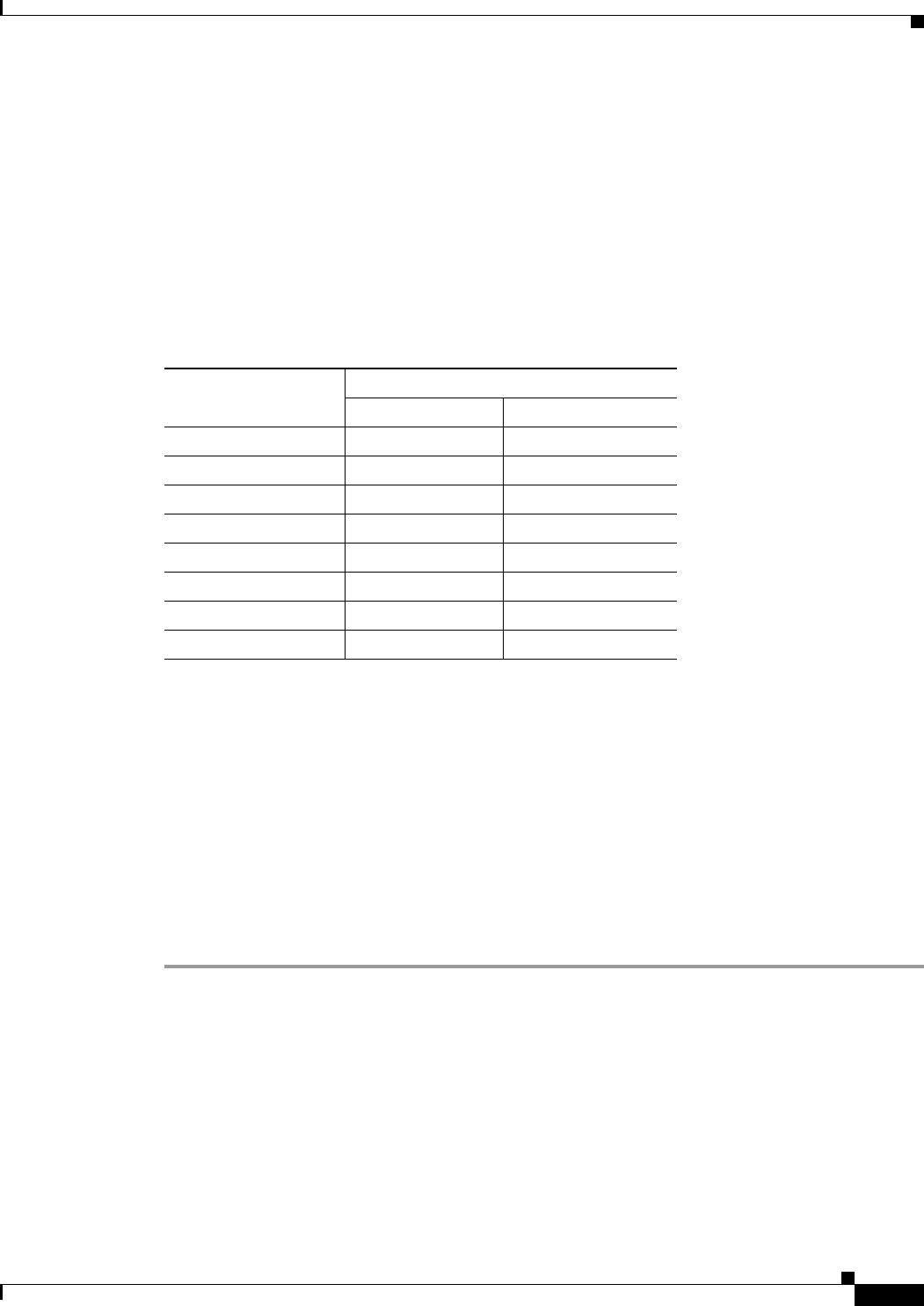
IEEE 802.11g (2.4-GHz Band)
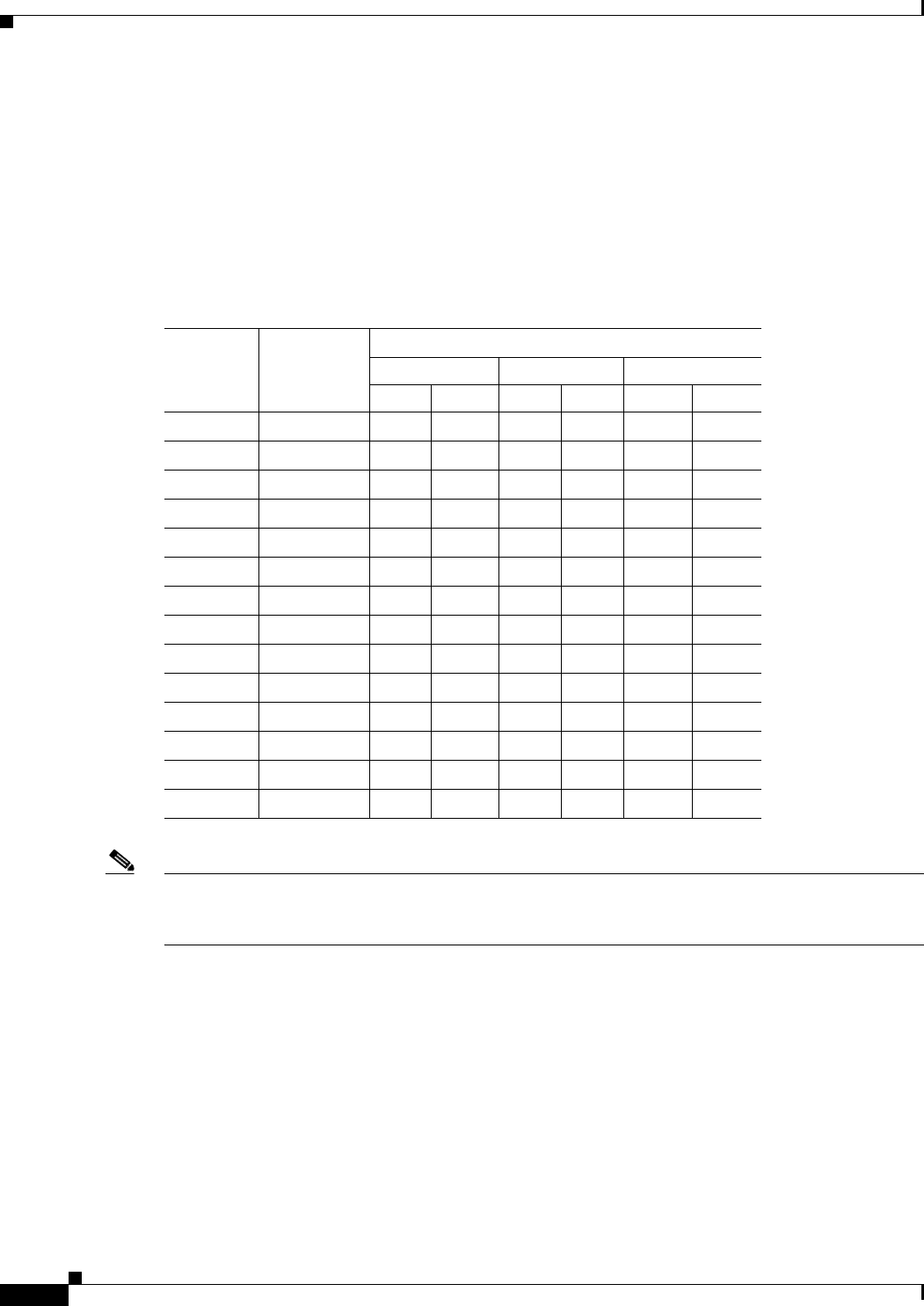
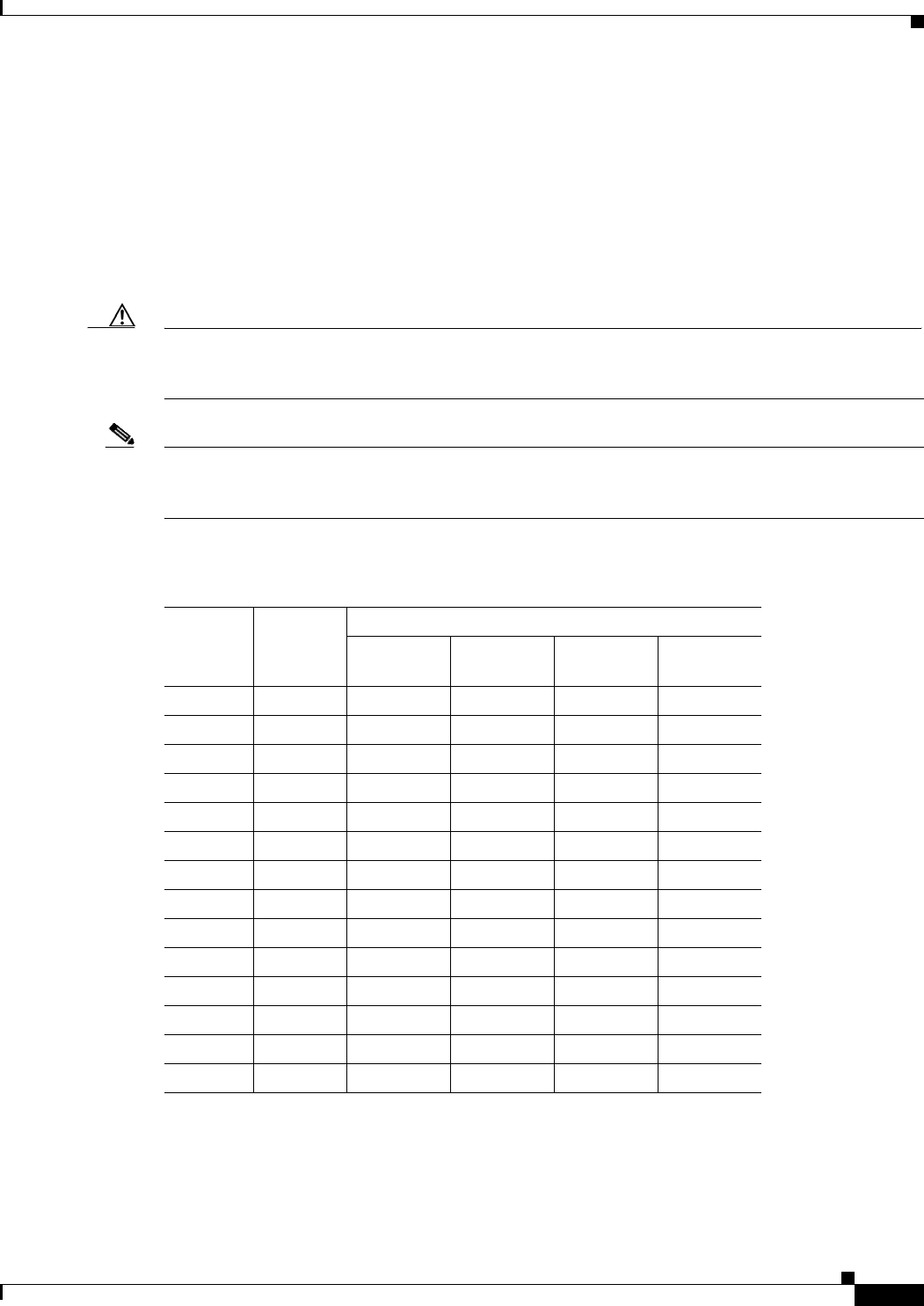
The channel identifiers, channel center frequencies, and regulatory domains of each IEEE 802.11b/g
22-MHz-wide channel are shown in Table 7-1.
Note Mexico is included in the Americas (–A) regulatory domain; however, channels 1 through 8 are for
indoor use only while channels 9 through 11 can be used indoors and outdoors. Users are responsible for
ensuring that the channel set configuration is in compliance with the regulatory standards of Mexico.
Table 7-1 Channels for IEEE 802.11b/g
Channel
Identifier
Center
Frequency
(MHz)
Regulatory Domains
Americas (–A) EMEA (–E) Japan (–J)
CCK OFDM CCK OFDM CCK OFDM
12412 X X X X X X
22417 X X X X X X
32422 X X X X X X
42427 X X X X X X
52432 X X X X X X
62437 X X X X X X
72442 X X X X X X
82447 X X X X X X
92452 X X X X X X
10 2457 X X X X X X
11 2462 X X X X X X
12 2467 – – X X X X
13 2472 – – X X X X
14 2484 – – – – – –
7-3
Channels and Maximum Power Settings for Cisco Aironet Lightweight Access Points
OL-11321-07
Chapter 7 Cisco Aironet 1300 Series Access Points Maximum Power Levels and Antenna Gains
Maximum Power Levels and Antenna Gains
IEEE 802.11b/g (2.4-GHz Band)
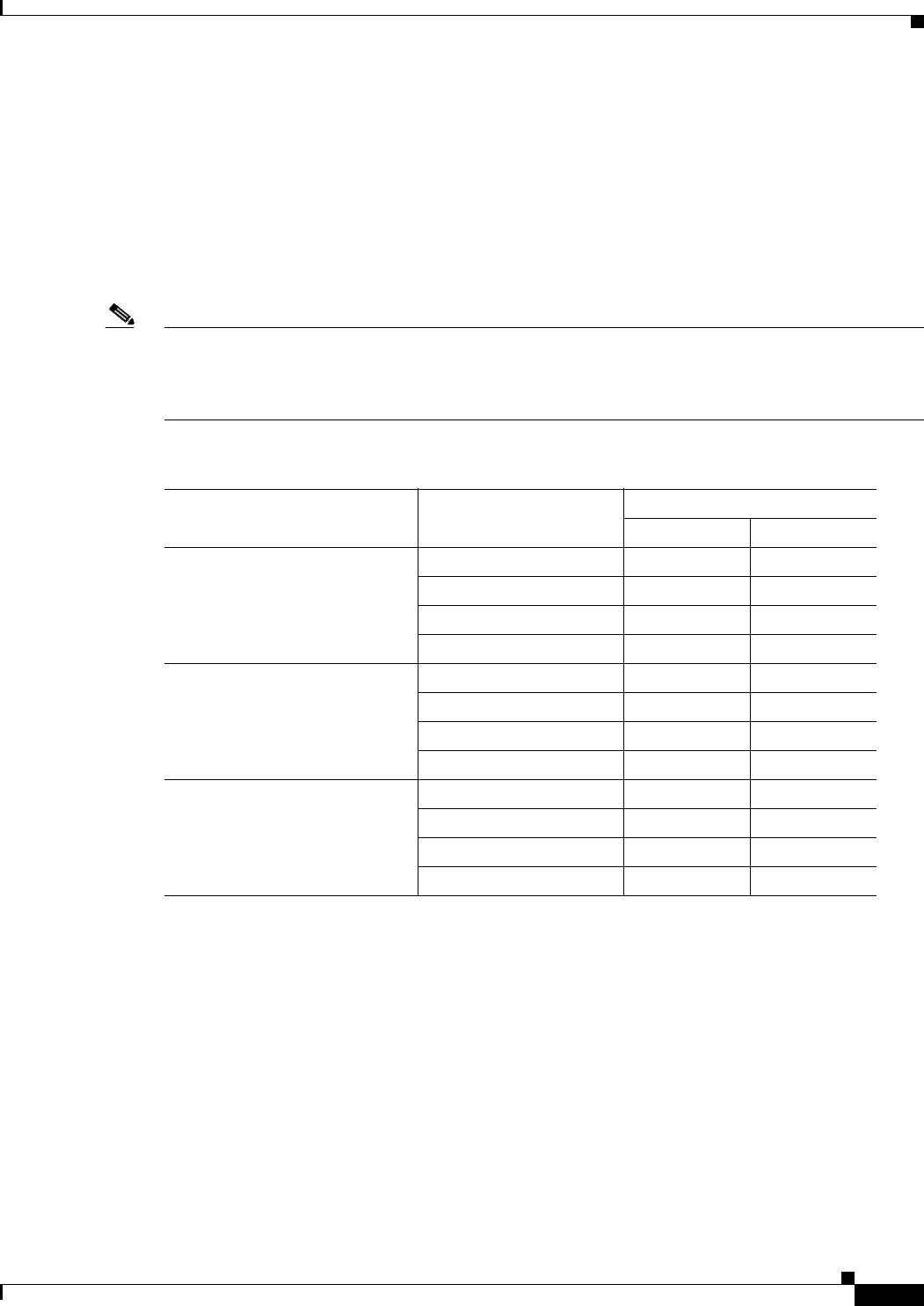
An improper combination of power level and antenna gain can result in equivalent isotropic radiated
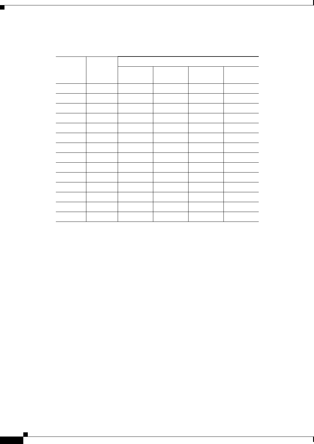
power (EIRP) above the amount allowed per regulatory domain. Table 7-2 indicates the IEEE 802.11b/g
maximum power levels and antenna gains allowed for each regulatory domain.
Note To meet regulatory restrictions, the external antenna access point/bridge and the external antenna must
be professionally installed. The network administration or other IT professional responsible for installing
and configuring the unit is a suitable professional installer. Following installation, access to the unit should
be password-protected by the network administrator to maintain regulatory compliance.
Table 7-2 Maximum Power Levels Per Antenna Gain for IEEE 802.11b/g
Regulatory Domain Antenna Gain (dBi)
Maximum Power Level (mW)
CCK OFDM
Americas (–A)
(4 W EIRP maximum) 2.2 (Omni) 100 30
5.2 (Omni) 100 30
9 (Patch) 100 30
10 (Yagi) 100 30
EMEA (–E)
(100 mW EIRP maximum) 2.2 (Omni) 50 30
5.2 (Omni) 20 20
9 (Patch) 10 10
10 (Yagi) 10 10
Japan (-J)
(10 mW/MHz EIRP maximum) 2.2 (Omni) 10 10
5.2 (Omni) 10 10
9 (Patch) 10 10
10 (Yagi) 10 10

7-4
Channels and Maximum Power Settings for Cisco Aironet Lightweight Access Points OL-11321-07
Chapter 7 Cisco Aironet 1300 Series Access Points
Changing the Lightweight Access Point Output Power
Changing the Lightweight Access Point Output Power
This section provides instructions for changing the 1300 series lightweight access point output power to
comply with the maximum power limits imposed by regulatory domains (see the “Maximum Power
Levels and Antenna Gains” section on page 7-3). Follow these instructions to change the output power
settings using your browser:
Note Administrator privileges may be required in order to change access point settings.
Note Regulatory domains are set at the factory and cannot be changed by the user.
The output power on the AIR-LAP1310G-x-K9 (where x is the regulatory domain) access points can be
changed only by using a Cisco wireless LAN controller (2600 series or 4400 series), the controllers on
a Cisco Wireless Services Module (WiSM), or using Cisco Wireless Control System (WCS).
Note See the Cisco Wireless LAN Controller Configuration Guide for more details on how to configure your
access point using the web-browser interface.
Follow these steps to change the AIR-LAP1310G-x-K9 (where x is the regulatory domain) access point’s
output power to meet local regulations using a controller:
Step 1 Open your Internet browser. You must use Microsoft Internet Explorer 6.0.2800 or a later release.
Step 2 Enter https://IP address (where IP address is the controller’s IP address) in the browser address line
and press Enter. A user login screen appears.
Step 3 Enter the username and password and press Enter. The controller’s summary page appears.
Note The username and password are case-sensitive.
Step 4 Click Wireless > 802.11b/g Radio and a list of associated access points appears.
Step 5 Choose the desired access point from the displayed list and click Configure. The radio settings page
appears.
Step 6 Scroll down to the Tx Power Level Assignment field, and click Custom. Custom indicates that the radio
output power is manually controlled by the Tx Power Configuration setting field.
7-5
Channels and Maximum Power Settings for Cisco Aironet Lightweight Access Points
OL-11321-07
Chapter 7 Cisco Aironet 1300 Series Access Points Changing the Lightweight Access Point Output Power
Step 7 In the Tx Power Level field, select the appropriate power level setting (1 to 8).
Based on the configured antenna gain, the configured channel, and the configured power level, the actual
transmit power at the access point can be reduced so that the specific country regulations are not
exceeded.
Table 7-3 lists the controller power settings and the corresponding output power levels for this example:
• 2.4-GHz (802.11b/g) operation:
–
EMEA (–E) regulatory domain and channel 2
–
5.2-dBi external antenna
• The manual controller Tx Power Level setting is 3 for 802.11b (CCK) data rates (see Table 7-2).
• The manual controller Tx Power Level setting is 2 for only 802.11g (OFDM) data rates (see
Table 7-2).
Step 8 Click Apply.
Step 9 Close your Internet browser.
For additional configuration information, refer to the Cisco Wireless LAN Controller Configuration
Guide.
Table 7-3 Available Output Power Levels
Controller
Tx Power Settings1
1. The Tx Power Level setting of 1 represents the maximum conducted power setting
for the access point. Each subsequent power level (such as 2, 3, 4, etc.) represents
an approximate 3-dBm reduction in transmit power from the previous power level.
Radio Output Power
802.11b (mW) 802.11g (mW)
1 (maximum)2
2. See Table 7-2 for the maximum power levels in the –E regulatory domain.
50 30
225 15
312 8
4 6 4
5 3 2
6 2 1
7-1 –
8 –
7-6
Channels and Maximum Power Settings for Cisco Aironet Lightweight Access Points OL-11321-07
Chapter 7 Cisco Aironet 1300 Series Access Points
Power Conversion Table
Power Conversion Table
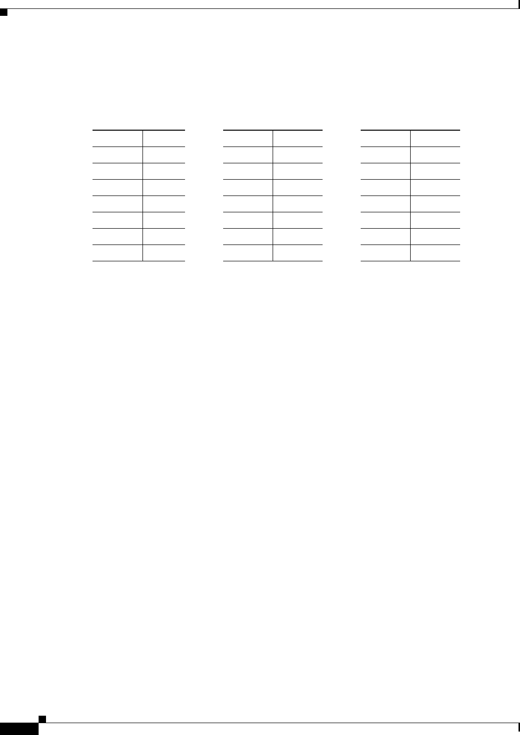
You can use Table 7-4 to convert power values from dBm to mW or from mW to dBm.
Table 7-4 Power Conversion Table
mW dBm mW dBm mW dBm
200 23 40 16 8 9
150 22 30 15 6 8
125 21 25 14 5 7
100 20 20 13 4 6
80 19 15 12 3 5
60 18 12 11 2 2
50 17 10 10 1–1

CHAPTER
8-1
Channels and Maximum Power Settings for Cisco Aironet Lightweight Access Points
OL-11321-07
8
Cisco Aironet 1500 Series Mesh Access Points
This chapter lists the 1500 series mesh access point IEEE 802.11b/g (2.4-GHz) and IEEE 802.11a
(5-GHz) channels and the maximum power levels supported by the world’s regulatory domains. For
additional product hardware information refer to the Cisco Aironet 1500 Series Outdoor Mesh Access
Point Hardware Installation Guide.
The AIR-LAP1510 access point model supports both 802.11b/g and 802.11a radios. The AIR-LAP1505
access point model only supports a 802.11b/g radio.
The following topics are covered in this chapter:
• Channels and Maximum Power Levels, page 8-2
• Antenna Settings, page 8-5
• Special Country Restrictions, page 8-7
8-2
Channels and Maximum Power Settings for Cisco Aironet Lightweight Access Points OL-11321-07
Chapter 8 Cisco Aironet 1500 Series Mesh Access Points
Channels and Maximum Power Levels
Channels and Maximum Power Levels
IEEE 802.11b/g (2.4-GHz Band)
When shipped from the factory, the access points support the channels and maximum power levels listed
in Table 8-1 for their regulatory domain.
Note In Table 8-1, the operating data rates (in Mbps) are shown in the CCK and OFDM table cells. For
example: CCK 1-11 indicates CCK data rates of 1 to 11 Mbps and All indicates all CCK and OFDM data
rates.
Note The AIR-LAP1505 access point model only supports the –A, –E, and –P regulatory domains.
Table 8-1 Channels and Maximum Conducted Power for the 802.11b/g Radio with Up to 8-dBi Antennas
Channel
ID
Center
Freq
(MHz)
Maximum Conducted Power Levels (dBm) in the Regulatory Domains
–A –C –E–K–N –S –P
CCK
1-11 OFDM
6-36 OFDM
48 OFDM
54 All All All CCK
1-11 OFDM
6-36 OFDM
48 OFDM
54 CCK
1-11 OFDM
6-36 OFDM
48 OFDM
54 All
12412 23 19.5 19.5 19.5 14 14 14 23 19.5 19.5 19.5 17 17 16 15 14
22417 23.5 21.5 21.5 21 14 14 14 23.5 21.5 21.5 21 17 17 16 15 14
32422 24 23 22 21 14 14 14 24 23 22 21 17 17 16 15 14
42427 24 24 22 21 14 14 14 24 24 22 21 17 17 16 15 14
52432 24 24 22 21 14 14 14 24 24 22 21 17 17 16 15 14
62437 24 24 22 21 14 14 14 24 24 22 21 17 17 16 15 14
72442 24 24 22 21 14 14 14 24 24 22 21 17 17 16 15 14
82447 24 24 22 21 14 14 14 24 24 22 21 17 17 16 15 14
92452 24 22.5 22 21 14 14 14 24 22.5 22 21 17 17 16 15 14
10 2457 23.5 21.5 21.5 21 14 14 14 23.5 21.5 21.5 21 17 17 16 15 14
11 2462 23 19.5 19.5 19.5 14 14 14 23 19.5 19.5 19.5 17 17 16 15 14
12 2467 – – – – 14 14 14 – – – 17 17 16 15 14
13 2472 – – – – 14 14 14 – – – 17 17 16 15 14
14 2484 – – – – – – – – – – – – – – – 14
8-3
Channels and Maximum Power Settings for Cisco Aironet Lightweight Access Points
OL-11321-07
Chapter 8 Cisco Aironet 1500 Series Mesh Access Points Channels and Maximum Power Levels
IEEE 802.11a (5-GHz Band)
When shipped from the factory, the access points support the channels and maximum power levels listed
in Table 8-2 and Table 8-3 for their regulatory domain.
Note In Table 8-2 and Table 8-3, the operating data rates (in Mbps) are shown in the OFDM table cells. For
example: OFDM 6-24 indicates 6 to 24 Mbps data rates and OFDM All indicates 6 to 54 Mbps data rates.
Table 8-2 Channels and Maximum Conducted Power for IEEE 802.11a Radio with Up to 17 dBi Antennas
Channel
ID
Center
Frequency
(MHz)
Maximum Conducted Power Levels (dBm) in the Regulatory Domains
–A –C –E –K
OFDM
6-24 OFDM
36 OFDM
48 OFDM
54 OFDM
6-24 OFDM
36 OFDM
48 OFDM
54 OFDM
6-24 OFDM
36 OFDM
48 OFDM
54 OFDM
All
(4900 to 5100 MHz)
–4920 –––––––––––––
–4940 –––––––––––––
–4950 20 20 18 17 –––––––––
–4960 –––––––––––––
–4980 20 20 18 17 –––––––––
–5040 –––––––––––––
–5060 –––––––––––––
–5080 –––––––––––––
5470 to 5725 MHz
100 5500 – – – – – – – – 191
1. Requires dynamic frequency selection (DFS) and transmit power control (TPC).
191 191191171
104 5520 – – – – – – – – 211211211201171
108 5540 – – – – – – – – 211211211201171
112 5560 – – – – – – – – 211211211201171
116 5580 – – – – – – – – 211211211201171
120 5600 – – – – – – – – 211211211201171
124 5620 – – – – – – – – 211211211201171
128 5640 – – – – – – – – 211211211201–
132 5660 – – – – – – – – 211211211201–
136 5680 – – – – – – – – 211211211201–
140 5700 – – – – – – – – 191191191191–
5725 to 5850 MHz
149 5745 26 24 23 20 23 23 23 20 –––––
153 5765 26 24 23 20 23 23 23 20 –––––
157 5785 26 24 23 20 23 23 23 20 –––––
161 5805 26 24 23 20 23 23 23 20 –––––
165 5825 26 24 23 20 –––––––––
8-4
Channels and Maximum Power Settings for Cisco Aironet Lightweight Access Points OL-11321-07
Chapter 8 Cisco Aironet 1500 Series Mesh Access Points
Channels and Maximum Power Levels
Table 8-3 Channels and Maximum Conducted Power for IEEE 802.11a Radio with Up to 17 dBi Antennas
Channel
ID
Center
Frequency
(MHz)
Maximum Conducted Power Levels (dBm) in the Regulatory Domains
–N –P –S
OFDM
6-24 OFDM
36 OFDM
48 OFDM
54 OFDM
6-24 OFDM
36 OFDM
48 OFDM
54 OFDM
6-24 OFDM
36 OFDM
48 OFDM
54
(4900 to 5100 MHz)
–4920 ––––17 17 17 17 ––––
–4940 ––––20 20 18 17 ––––
–4950 ––––––––––––
–4960 ––––20 20 18 17 ––––
–4980 ––––201
1. Limited license until 11/2007.
201181171––––
–5040 ––––202
2. Limited license until 11/2007.
201181171––––
–5060 ––––201201181171––––
–5080 ––––201201181171––––
5470 to 5725 MHz
100 5500 ––––––––––––
104 5520 ––––––––––––
108 5540 ––––––––––––
112 5560 ––––––––––––
116 5580 ––––––––––––
120 5600 ––––––––––––
124 5620 ––––––––––––
128 5640 ––––––––––––
132 5660 ––––––––––––
136 5680 ––––––––––––
140 5700 ––––––––––––
5725 to 5850 MHz
149 5745 26 24 23 20 ––––20 20 20 20
153 5765 26 24 23 20 ––––20 20 20 20
157 5785 26 24 23 20 ––––20 20 20 20
161 5805 26 24 23 20 ––––20 20 20 20
165 5825 ––––––––––––
8-5
Channels and Maximum Power Settings for Cisco Aironet Lightweight Access Points
OL-11321-07
Chapter 8 Cisco Aironet 1500 Series Mesh Access Points Antenna Settings
Antenna Settings
Maximum Power Levels Allowed in Some Regulatory Domains
An improper combination of power level and antenna gain can result in equivalent isotropic radiated power
(EIRP) above the amount allowed per regulatory domain. Table 8-4 indicates the maximum power levels
allowed with an 8 dBi external antenna in the –A and –N regulatory domains.
Caution To avoid exceeding maximum conducted power levels in the –A , –N, and –E regulatory domains when
using an 8 dBi antennas, you must manually set the access point output power level to not exceed the
value shown in Table 8-4 and Table 8-5.
Note In Table 8-4 and Table 8-5, the operating data rates (in Mbps) are shown in the CCK and OFDM table
cells. For example: OFDM 9-24 indicates 9 to 24Mbps data rates and All OFDM indicates 6 to 54 Mbps
data rates.
Table 8-4 Maximum Power Levels for the 802.11b/g Radio with 8-dBi Antenna
(for –A and –N Regulatory Domains)
Channel
ID
Center
Frequency
(MHz)
Maximum Conducted Average Power Levels in dBm
CCK
1-11 OFDM
6-36 OFDM
48 OFDM
54
12412 23 19.5 19.5 19.5
22417 23.5 21.5 21.5 21
32422 24 23 22 21
42427 24 24 22 21
52432 24 24 22 21
62437 24 24 22 21
72442 24 24 22 21
82447 24 24 22 21
92452 24 22.5 22 21
10 2457 23.5 21.5 21.5 21
11 2462 23 19.5 19.5 19.5
12 2467 – – – –
13 2472 – – – –
14 2484 – – – –
8-6
Channels and Maximum Power Settings for Cisco Aironet Lightweight Access Points OL-11321-07
Chapter 8 Cisco Aironet 1500 Series Mesh Access Points
Antenna Settings
Table 8-5 Maximum Power Levels for the 802.11b/g Radio with 8-dBi Antenna
(for –E Regulatory Domain)
Channel
ID
Center
Frequency
(MHz)
Maximum Conducted Average Power Levels in dBm
CCK
1-11 OFDM
6-36 OFDM
48 OFDM
54
12412 12 12 12 12
22417 12 12 12 12
32422 12 12 12 12
42427 12 12 12 12
52432 12 12 12 12
62437 12 12 12 12
72442 12 12 12 12
82447 12 12 12 12
92452 12 12 12 12
10 2457 12 12 12 12
11 2462 12 12 12 12
12 2467 12 12 12 12
13 2472 12 12 12 12
14 2484 12 12 12 12
8-7
Channels and Maximum Power Settings for Cisco Aironet Lightweight Access Points
OL-11321-07
Chapter 8 Cisco Aironet 1500 Series Mesh Access Points Antenna Settings
Special Country Restrictions
Table 8-6 lists special restrictions for wireless operation in some countries.
Table 8-6 Special Country Restrictions for Wireless Operation
Country Frequency
Band (GHz) Regulatory
Domain Special Limitation and Restrictions
Australia 5 –N 5 GHz maximum antenna gain limited to 7 dBi.
China 5 –C 5 GHz maximum antenna gain limited to 9.5 dBi.
EU countries 5 –E 5 GHz maximum antenna gain limited to 7 dBi.
Japan 4.9 and 5 –P License required for operation in the 4.9 and 5 GHz bands.
South Korea 5–K 5 GHz maximum antenna gain limited to 7 dBi.
2.4 –E1
1. The LAP1505 access point.
2.4 GHz maximum antenna gain limited to 6 dBi.
Mexico 2.4 –N End user must limit 2.4 GHz operation to 2450 to 2483.5 MHz and 36
dBm EIRP2.
2. EIRP (dBm) = maximum output power (dBm) + antenna gain (dBi)
New Zealand 5 –N 5 GHz maximum antenna gain limited to 7 dBi.
Russian Federation 5–E End user must limit 5 GHz operation to 5650 to 5725 MHz.
Singapore 2.4 –S • Wireless operation is intended for use in confined areas of
buildings and localized on-site areas. An IDA license is required
for operation over public areas.
• Wireless operation is limited to a maximum of 23 dBm EIRP1.
5 –S • Wireless operation is intended for use in confined areas of
buildings and localized on-site areas. An IDA license is required
for operation over public areas.
• 5 GHz maximum antenna gain limited to 9.5 dBi.
• An IDA license is required for operation from
30 dBm to 36 dBm EIRP.
United States 4.9 –A The use of the 4.9-GHz band requires a license and may be used only
by qualified Public Safety operators as defined in section 90.20 of the
FCC rules.
2.4 –A and –N 2.4 GHz maximum antenna gain limited to 8 dBi.
8-8
Channels and Maximum Power Settings for Cisco Aironet Lightweight Access Points OL-11321-07
Chapter 8 Cisco Aironet 1500 Series Mesh Access Points
Changing the Lightweight Access Point Output Power
Changing the Lightweight Access Point Output Power
This section provides instructions for changing the 1500 series access point output power to comply with
the maximum power limits imposed by special regulatory and country restrictions (see the “Antenna
Settings” section on page 8-5). Follow these instructions to change the output power settings using a
controller and your browser:
Note Administrator privileges may be required in order to change access point settings.
Note Regulatory domains are set at the factory and cannot be changed by the user.
Caution To meet regulatory restrictions, the access point and the external antenna must be professionally
installed. The network administration or other IT professional responsible for installing and configuring the
unit is a suitable professional installer. Following installation, access to the unit should be
password-protected by the network administrator to maintain regulatory compliance.
The output power on the 1500 series access points can be changed only by using a Cisco wireless LAN
controller (2600 series or 4400 series), the controllers on a Cisco Wireless Services Module (WiSM), or
using Cisco Wireless Control System (WCS).
Note See the Cisco Wireless LAN Controller Configuration Guide for more details on how to to configure your
access point using the web-browser interface.
Follow these steps to change the 1500 series access point’s output power to meet local regulations using
a controller:
Step 1 Open your Internet browser. You must use Microsoft Internet Explorer 6.0.2800 or a later release.
Step 2 Enter https://IP address (where IP address is the controller’s IP address) in the browser address line
and press Enter. A user login screen appears.
Step 3 Enter the username and password and press Enter. The controller’s summary page appears.
Note The username and password are case-sensitive.
Step 4 Click Wireless > 802.11a Radios or 802.11b/g Radios and a list of associated access points appears.
Step 5 Choose the desired access point from the displayed list and click Configure. The the radio settings page
appears.
Step 6 Scroll down to the Tx Power Level Assignment field, and click Custom.
Custom indicates that the radio output power is manually controlled by the Tx Power Configuration
setting field.
8-9
Channels and Maximum Power Settings for Cisco Aironet Lightweight Access Points
OL-11321-07
Chapter 8 Cisco Aironet 1500 Series Mesh Access Points Changing the Lightweight Access Point Output Power
Step 7 In the Tx Power Level field, select the appropriate power level setting (1 to 5).
Based on the operating channel, the regulatory domain, and the controller power level setting (1 to 5),
the actual transmit power at the access point can be reduced to comply with special regulatory or country
restrictions.
Note The access point supports only two output power levels for the 2.4-GHz radio and three output
power levels for the 5-GHz radio.
Note Table 8-1 and Table 8-2 list the access point maximum output power levels supported for each
regulatory domain when the access point is shipped from the factory.
Table 8-7 lists the controller power settings and the corresponding output power levels for these two
examples:
• 2.4-GHz (802.11b/g) operation:
–
American regulatory domain
–
Channel 3 using 11-Mbps data rates
• 5-GHz (802.11a) operation:
–
American regulatory domain
–
Channel 149 using 36-Mbps data rates
Step 8 Click Apply.
Step 9 Close your Internet browser.
For additional configuration information, refer to the Cisco Wireless LAN Controller Configuration
Guide.
Table 8-7 Example of Output Power Levels
Controller
Tx Power Settings1
1. The Tx Power Level setting of 1 represents the maximum conducted power
setting for the access point. Each subsequent controller power level (such as
2, 3, 4, etc.) represents an approximate 3-dBm reduction in transmit power
from the previous power level.
Radio Output Power
802.11b/g
(dBm) 802.11a (dBm)
1 (maximum) 242
2. The maximum output power level obtained from Table 8-1.
243
3. The maximum output power level obtained from Table 8-2.
221 21

8-10
Channels and Maximum Power Settings for Cisco Aironet Lightweight Access Points OL-11321-07
Chapter 8 Cisco Aironet 1500 Series Mesh Access Points
Changing the Lightweight Access Point Output Power

CHAPTER
9-1
Channels and Maximum Power Settings for Cisco Aironet Lightweight Access Points
OL-11321-07
9
Cisco Aironet 1520 Series Mesh Access Points
This chapter lists the 1520 series mesh access point IEEE 802.11b/g (2.4-GHz) and IEEE 802.11a
(5-GHz) channels and the maximum power levels supported by the world’s regulatory domains. For
additional product hardware information refer to the Cisco Aironet 1520 Series Outdoor Mesh Access
Point Hardware Installation Guide.
The AIR-LAP1522 access point model supports both 802.11b/g and 802.11a radios. The AIR-LAP1521
access point model only supports a 802.11b/g radio.
The following topics are covered in this chapter:
• Channels and Maximum Power Levels, page 9-2
• Changing the Lightweight Access Point Output Power, page 9-14

9-2
Channels and Maximum Power Settings for Cisco Aironet Lightweight Access Points OL-11321-07
Chapter 9 Cisco Aironet 1520 Series Mesh Access Points
Channels and Maximum Power Levels
Channels and Maximum Power Levels
AIR-LAP1521G
IEEE 802.11b/g (2.4-GHz Band)
When shipped from the factory, the AIR-LAP1521G single radio access points support the channels and
maximum power levels listed in Table 9-1 for their regulatory domains with up to 5.5 dBi antennas.
Note In Table 9-1 and Table 9-2, the operating data rates (in Mbps) are shown in the CCK and OFDM table
cells. For example: CCK 1-11 indicates CCK data rates of 1 to 11 Mbps and All indicates all CCK and
OFDM data rates.
Table 9-1 Channels and Maximum Conducted Power for the 802.11b/g Radio with Up to
5.5-dBi Antennas
Channel
ID
Center
Frequency
(MHz)
Maximum Conducted Power Levels (dBm) in the Regulatory
Domains
–A –E –P
CCK
1-11 OFDM
6-48 OFDM
54 All CCK
1-11 OFDM
6-54
12412 28 25 25 14 14 16
22417 28 26 26 14 14 16
32422 28 27 27 14 14 16
42427 28 27 27 14 14 16
52432 28 27 27 14 14 16
62437 28 27 27 14 14 16
72442 28 27 27 14 14 16
82447 28 27 27 14 14 16
92452 28 26 26 14 14 16
10 2457 28 26 26 14 14 16
11 2462 28 25 25 14 14 16
12 2467 – – – 14 14 16
13 2472 – – – 14 14 16
14 2484 – – – 14

9-3
Channels and Maximum Power Settings for Cisco Aironet Lightweight Access Points
OL-11321-07
Chapter 9 Cisco Aironet 1520 Series Mesh Access Points Channels and Maximum Power Levels
Table 9-2 indicates the the AIR-LAP1521G single radio access point channel identifiers, channel center
frequencies, and maximum power levels for each channel allowed by the regulatory domains for the
2.4-GHz radio with up to 8-dBi antennas.
Table 9-2 Channels and Maximum Conducted Power for the 802.11b/g Radio with Up to
8.0-dBi Antennas
Channel
ID
Center
Frequency
(MHz)
Maximum Conducted Power Levels (dBm) in the Regulatory
Domains
–A –E –P
CCK
1-11 OFDM
6-48 OFDM
54 All CCK
1-11 OFDM
6-54
12412 28 24 24 12 14 16
22417 28 25 25 12 14 16
32422 28 26 26 12 14 16
42427 28 27 27 12 14 16
52432 28 27 27 12 14 16
62437 28 27 27 12 14 16
72442 28 27 27 12 14 16
82447 28 27 26 12 14 16
92452 28 26 26 12 14 16
10 2457 28 25 25 12 14 16
11 2462 28 24 24 12 14 16
12 2467 –––12 14 16
13 2472 –––12 14 16
14 2484 ––– 14
9-4
Channels and Maximum Power Settings for Cisco Aironet Lightweight Access Points OL-11321-07
Chapter 9 Cisco Aironet 1520 Series Mesh Access Points
Channels and Maximum Power Levels
AIR-LAP1522AG
IEEE 802.11b/g (2.4-GHz Band)
When shipped from the factory, the AIR-LAP1522AG dual radio access points support the channels and
maximum power levels listed in Table 9-1 for the regulatory domains using the 2.4-GHz radio with up
to 5.5 dBi antennas.
Note In Table 9-1 and Table 9-2, the operating data rates (in Mbps) are shown in the CCK and OFDM table
cells. For example: CCK 1-11 indicates CCK data rates of 1 to 11 Mbps and All indicates all CCK and
OFDM data rates.
Table 9-3 Channels and Maximum Conducted Power for the 802.11b/g Radio with Up to
5.5-dBi Antennas
Channel
ID
Center
Frequency
(MHz)
Maximum Conducted Power Levels (dBm) in the Regulatory
Domains
–A –E –P
CCK
1-11 OFDM
6-48 OFDM
54 All CCK
1-11 OFDM
6-54
12412 28 25 25 14 14 16
22417 28 26 26 14 14 16
32422 28 27 27 14 14 16
42427 28 27 27 14 14 16
52432 28 27 27 14 14 16
62437 28 27 27 14 14 16
72442 28 27 27 14 14 16
82447 28 27 27 14 14 16
92452 28 26 26 14 14 16
10 2457 28 26 26 14 14 16
11 2462 28 25 25 14 14 16
12 2467 – – – 14 14 16
13 2472 – – – 14 14 16
14 2484 – – – 14
9-5
Channels and Maximum Power Settings for Cisco Aironet Lightweight Access Points
OL-11321-07
Chapter 9 Cisco Aironet 1520 Series Mesh Access Points Channels and Maximum Power Levels
Table 9-2 indicates the the AIR-LAP1522AG dual radio access point channel identifiers, channel center
frequencies, and maximum power levels for each channel allowed by the regulatory domains for the
2.4-GHz radio with up to 8-dBi antennas.
IEEE 802.11a (5-GHz Band)
When shipped from the factory, the AIR-LAP1522AG access points support the channels and maximum
power levels listed in Table 9-5 for their regulatory domains with up to 8 dBi antennas.
Table 9-4 Channels and Maximum Conducted Power for the 802.11b/g Radio with Up to
8.0-dBi Antennas
Channel
ID
Center
Frequency
(MHz)
Maximum Conducted Power Levels (dBm) in the Regulatory
Domains
–A –E –P
CCK
1-11 OFDM
6-48 OFDM
54 All CCK
1-11 OFDM
6-54
12412 28 24 24 12 14 16
22417 28 25 25 12 14 16
32422 28 26 26 12 14 16
42427 28 27 27 12 14 16
52432 28 27 27 12 14 16
62437 28 27 27 12 14 16
72442 28 27 27 12 14 16
82447 28 27 26 12 14 16
92452 28 26 26 12 14 16
10 2457 28 25 25 12 14 16
11 2462 28 24 24 12 14 16
12 2467 –––12 14 16
13 2472 –––12 14 16
14 2484 ––– 14
9-6
Channels and Maximum Power Settings for Cisco Aironet Lightweight Access Points OL-11321-07
Chapter 9 Cisco Aironet 1520 Series Mesh Access Points
Channels and Maximum Power Levels
Note In Table 9-5, Table 9-6, and Table 9-7, the operating data rates (in Mbps) are shown in the OFDM table
cells. For example: OFDM 6-36 indicates 6 to 36 Mbps data rates.
Table 9-5 Channels and Maximum Conducted Power for IEEE 802.11a Radio with Up to 8 dBi Antennas
Channel
ID
Center
Freq
(MHz)
Band-
width
(MHz)
Maximum Conducted Power Levels (dBm) in the Regulatory Domains
–A –C –E –K –N –P –S –T
OFDM
6-18 OFDM
24-36 OFDM
48 OFDM
54 All All All OFDM
6-18 OFDM
24-36 OFDM
48 OFDM
54 All All OFDM
6-18 OFDM
24-36 OFDM
48 OFDM
54
(4900 to 5100 MHz)
14942.5 520 20 20 20 –––––––––––––
24947.5 20 20 20 20 –––––––––––––
34952.5 20 20 20 20 –––––––––––––
44957.5 20 20 20 20 –––––––––––––
54962.5 20 20 20 20 –––––––––––––
64967.5 20 20 20 20 –––––––––––––
74972.5 20 20 20 20 –––––––––––––
84977.5 20 20 20 20 –––––––––––––
94982.5 20 20 20 20 –––––––––––––
10 4987.5 20 20 20 20 –––––––––––––
11 4945 10 20 20 20 20 –––––––––––––
12 5950 20 20 20 20 –––––––––––––
13 4955 20 20 20 20 –––––––––––––
14 4960 20 20 20 20 –––––––––––––
15 4965 20 20 20 20 –––––––––––––
16 4970 20 20 20 20 –––––––––––––
17 5975 20 20 20 20 –––––––––––––
18 4980 20 20 20 20 –––––––––––––
19 4985 20 20 20 20 –––––––––––––
184 4920 20 –––––––––––20 –––––
188 4940 –––––––––––20 –––––
20 4950 20 20 20 20 –––––––––––––
21 4955 20 20 20 20 –––––––––––––
22/192 4960 20 20 20 20 –––––––20 –––––
23 4965 20 20 20 20 –––––––––––––
24 4970 20 20 20 20 –––––––––––––
25 5975 20 20 20 20 –––––––––––––
26/196 4980 20 20 20 20 –––––––20 –––––
85040 –––––––––––20 –––––
12 5060 –––––––––––20 –––––
– – –––––––––––––––––

9-7
Channels and Maximum Power Settings for Cisco Aironet Lightweight Access Points
OL-11321-07
Chapter 9 Cisco Aironet 1520 Series Mesh Access Points Channels and Maximum Power Levels
(5250 to 5350)
52 5260 20 –––––– ––––––––––
56 5280 191191191191– – 191––––––––––
60 5300 191191191191– – 191––––––––––
64 5320 191191191191– – 191––––––––––
(5470 fto 5350)
100 5500 20 191191191191–221191––––––191191191191
104 5520 191191191191–221191––––––191191191191
108 5540 191191191191–221191––––––191191191191
112 5560 191191191191–221191––––––191191191191
116 5580 191191191191–221191––––––191191191191
120 5600 –––––221191––––––191191191191
124 5620 –––––221191––––––191191191191
128 5640 –––––221–––––––191191191191
132 5660 191191191191–221–––––––191191191191
136 5680 191191191191–221–––––––191191191191
140 5700 191191191191–221–––––––191191191191
5725 to 5850 MHz
149 5745 20 28 27 25 24 22 – – 28 27 25 24 –22 28 27 25 24
153 5765 28 27 25 24 22 – – 28 27 25 24 –22 28 27 25 24
157 5785 28 27 25 24 22 – – 28 27 25 24 –22 28 27 25 24
161 5805 28 27 25 24 22 – – 28 27 25 24 –22 28 27 25 24
165 5825 28 27 25 24 22 – – 28 27 25 24 –22 28 27 25 24
1. Requires dynamic frequency selection (DFS) and transmit power control (TPC).
Table 9-5 Channels and Maximum Conducted Power for IEEE 802.11a Radio with Up to 8 dBi Antennas (continued)
Channel
ID
Center
Freq
(MHz)
Band-
width
(MHz)
Maximum Conducted Power Levels (dBm) in the Regulatory Domains
–A –C –E –K –N –P –S –T
OFDM
6-18 OFDM
24-36 OFDM
48 OFDM
54 All All All OFDM
6-18 OFDM
24-36 OFDM
48 OFDM
54 All All OFDM
6-18 OFDM
24-36 OFDM
48 OFDM
54

9-8
Channels and Maximum Power Settings for Cisco Aironet Lightweight Access Points OL-11321-07
Chapter 9 Cisco Aironet 1520 Series Mesh Access Points
Channels and Maximum Power Levels
Table 9-6 indicates the channel identifiers, channel center frequencies, and maximum power levels for
each channel allowed by the regulatory domains for a 5-GHz radio with up to 14-dBi antennas.
Table 9-6 Channels and Maximum Conducted Power for IEEE 802.11a Radio with Up to 14 dBi Antennas
Channel
ID
Center
Freq
(MHz)
Band-
width
(MHz)
Maximum Conducted Power Levels (dBm) in the Regulatory Domains
–A –C –E –K –N –P –S –T
OFDM
6-18 OFDM
24-36 OFDM
48 OFDM
54 All All All OFDM
6-18 OFDM
24-36 OFDM
48 OFDM
54 All All OFDM
6-18 OFDM
24-36 OFDM
48 OFDM
54
(4900 to 5100 MHz)
14942.5 5 20 20 20 20 –––––––––––––
24947.5 20 20 20 20 –––––––––––––
34952.5 20 20 20 20 –––––––––––––
44957.5 20 20 20 20 –––––––––––––
54962.5 20 20 20 20 –––––––––––––
64967.5 20 20 20 20 –––––––––––––
74972.5 20 20 20 20 –––––––––––––
84977.5 20 20 20 20 –––––––––––––
94982.5 20 20 20 20 –––––––––––––
10 4987.5 20 20 20 20 –––––––––––––
11 4945 10 20 20 20 20 –––––––––––––
12 5950 20 20 20 20 –––––––––––––
13 4955 20 20 20 20 –––––––––––––
14 4960 20 20 20 20 –––––––––––––
15 4965 20 20 20 20 –––––––––––––
16 4970 20 20 20 20 –––––––––––––
17 5975 20 20 20 20 –––––––––––––
18 4980 20 20 20 20 –––––––––––––
19 4985 20 20 20 20 –––––––––––––
184 4920 20 –––––––––––17 –––––
188 4940 –––––––––––20 –––––
20 4950 20 20 20 20 –––––––––––––
21 4955 20 20 20 20 –––––––––––––
22/192 4960 20 20 20 20 –––––––20 –––––
23 4965 20 20 20 20 –––––––––––––
24 4970 20 20 20 20 –––––––––––––
25 5975 20 20 20 20 –––––––––––––
26/196 4980 20 20 20 20 –––––––20 –––––
85040 –––––––––––20 –––––
12 5060 –––––––––––20 –––––
16 5080 –––––––––––––––––

9-9
Channels and Maximum Power Settings for Cisco Aironet Lightweight Access Points
OL-11321-07
Chapter 9 Cisco Aironet 1520 Series Mesh Access Points Channels and Maximum Power Levels
(5250 to 5350)
52 5260 20 –––––– – ––––––––
56 5280 131131131131–––– ––––––––
60 5300 131131131131–––– ––––––––
64 5320 131131131131–––– ––––––––
(5470 fto 5350)
100 5500 20 131131131131–161–– ––––131131131131
104 5520 131131131131–161–– ––––131131131131
108 5540 131131131131–161–– ––––131131131131
112 5560 131131131131–161–– ––––131131131131
116 5580 131131131131–161–– ––––131131131131
120 5600 –––––161–– ––––131131131131
124 5620 –––––161–– ––––131131131131
128 5640 –––––161–– ––––131131131131
132 5660 131131131131–161–– ––––131131131131
136 5680 131131131131–161–– ––––131131131131
140 5700 131131131131–161–– ––––131131131131
5725 to 5850 MHz
149 5745 20 28 27 25 24 – – 20 28 27 25 24 – – 28 27 25 24
153 5765 28 27 25 24 – – 20 28 27 25 24 – – 28 27 25 24
157 5785 28 27 25 24 – – 20 28 27 25 24 – – 28 27 25 24
161 5805 28 27 25 24 – – 20 28 27 25 24 – – 28 27 25 24
165 5825 28 27 25 24 –––28 27 25 24 – – 28 27 25 24
1. Requires DFS and TPC.
Table 9-6 Channels and Maximum Conducted Power for IEEE 802.11a Radio with Up to 14 dBi Antennas (continued)
Channel
ID
Center
Freq
(MHz)
Band-
width
(MHz)
Maximum Conducted Power Levels (dBm) in the Regulatory Domains
–A –C –E –K –N –P –S –T
OFDM
6-18 OFDM
24-36 OFDM
48 OFDM
54 All All All OFDM
6-18 OFDM
24-36 OFDM
48 OFDM
54 All All OFDM
6-18 OFDM
24-36 OFDM
48 OFDM
54
9-10
Channels and Maximum Power Settings for Cisco Aironet Lightweight Access Points OL-11321-07
Chapter 9 Cisco Aironet 1520 Series Mesh Access Points
Channels and Maximum Power Levels
Table 9-7 indicates the channel identifiers, channel center frequencies, and maximum power levels for
each channel allowed by the regulatory domains for a 5-GHz radio with up to 17-dBi antennas.
Table 9-7 Channels and Maximum Conducted Power for IEEE 802.11a Radio with Up to 17 dBi Antennas
Channel
ID
Center
Freq
(MHz)
Band-
width
(MHz)
Maximum Conducted Power Levels (dBm) in the Regulatory Domains
–A –C –E –K –N –P –S –T
OFDM
6-18 OFDM
24-36 OFDM
48 OFDM
54 All All All OFDM
6-18 OFDM
24-36 OFDM
48 OFDM
54 All All OFDM
6-18 OFDM
24-36 OFDM
48 OFDM
54
(4900 to 5100 MHz)
14942.5 520 20 20 20 –––––––––––––
24947.5 20 20 20 20 –––––––––––––
34952.5 20 20 20 20 –––––––––––––
44957.5 20 20 20 20 –––––––––––––
54962.5 20 20 20 20 –––––––––––––
64967.5 20 20 20 20 –––––––––––––
74972.5 20 20 20 20 –––––––––––––
84977.5 20 20 20 20 –––––––––––––
94982.5 20 20 20 20 –––––––––––––
10 4987.5 20 20 20 20 –––––––––––––
11 4945 10 20 20 20 20 –––––––––––––
12 5950 20 20 20 20 –––––––––––––
13 4955 20 20 20 20 –––––––––––––
14 4960 20 20 20 20 –––––––––––––
15 4965 20 20 20 20 –––––––––––––
16 4970 20 20 20 20 –––––––––––––
17 5975 20 20 20 20 –––––––––––––
18 4980 20 20 20 20 –––––––––––––
19 4985 20 20 20 20 –––––––––––––
184 4920 20 –––––––––––20 –––––
188 4940 –––––––––––20 –––––
20 4950 20 20 20 20 –––––––––––––
21 4955 20 20 20 20 –––––––––––––
22/192 4960 20 20 20 20 –––––––20 –––––
23 4965 20 20 20 20 –––––––––––––
24 4970 20 20 20 20 –––––––––––––
25 5975 20 20 20 20 –––––––––––––
26/196 4980 20 20 20 20 –––––––20 –––––
85040 –––––––––––20 –––––
12 5060 –––––––––––20 –––––
– – –––––––––––––––––
9-11
Channels and Maximum Power Settings for Cisco Aironet Lightweight Access Points
OL-11321-07
Chapter 9 Cisco Aironet 1520 Series Mesh Access Points Channels and Maximum Power Levels
(5250 to 5350)
52 5260 20 –––––– ––––––––––
56 5280 –––––– ––––––––––
60 5300 –––––– ––––––––––
64 5320 –––––– ––––––––––
(5470 fto 5350)
100 5500 20 –––––101–––––––––––
104 5520 –––––101–––––––––––
108 5540 –––––101–––––––––––
112 5560 –––––101–––––––––––
116 5580 –––––101–––––––––––
120 5600 –––––101–––––––––––
124 5620 –––––101–––––––––––
128 5640 –––––101–––––––––––
132 5660 –––––101–––––––––––
136 5680 –––––101–––––––––––
140 5700 –––––101–––––––––––
5725 to 5850 MHz
149 5745 20 28 27 25 24 – – 20 28 27 25 24 – – 28 27 25 24
153 5765 28 27 25 24 – – 20 28 27 25 24 – – 28 27 25 24
157 5785 28 27 25 24 – – 20 28 27 25 24 – – 28 27 25 24
161 5805 28 27 25 24 – – 20 28 27 25 24 – – 28 27 25 24
165 5825 28 27 25 24 –––28 27 25 24 – – 28 27 25 24
1. Requires DFS and TPC.
Table 9-7 Channels and Maximum Conducted Power for IEEE 802.11a Radio with Up to 17 dBi Antennas (continued)
Channel
ID
Center
Freq
(MHz)
Band-
width
(MHz)
Maximum Conducted Power Levels (dBm) in the Regulatory Domains
–A –C –E –K –N –P –S –T
OFDM
6-18 OFDM
24-36 OFDM
48 OFDM
54 All All All OFDM
6-18 OFDM
24-36 OFDM
48 OFDM
54 All All OFDM
6-18 OFDM
24-36 OFDM
48 OFDM
54
9-12
Channels and Maximum Power Settings for Cisco Aironet Lightweight Access Points OL-11321-07
Chapter 9 Cisco Aironet 1520 Series Mesh Access Points
Channels and Maximum Power Levels
Minimum 5-GHz Radio Power Levels
Table 9-8 lists the minimum power levels supported by the 5-GHz radio for the various channels and
regulatory domains.
Note When the minimum radio power level is reached with a controller power setting (1 to 5), changing the
controller power setting to a lower value does not result in a lower radio output power level. For example,
if the minimum radio power level corresponds to controller level 3, then levels 4 and 5 also correspond
to the same power level.
Table 9-8 5-GHz Radio Minimum Power Levels
Channel
ID
Center
Freq
(MHz)
Band-
width
(MHz)
Minimum Radio Power Levels (dBm) in the Regulatory Domains
–A –C –E –K –N –P –S –T
OFDM
6-18 OFDM
24-36 OFDM
48 OFDM
54 All All All OFDM
6-18 OFDM
24-36 OFDM
48 OFDM
54 All All OFDM
6-18 OFDM
24-36 OFDM
48 OFDM
54
(4900 to 5100 MHz)
14942.5 5 8888–––––––––––––
24947.5 8888–––––––––––––
34952.5 8888–––––––––––––
44957.5 8888–––––––––––––
54962.5 8888–––––––––––––
64967.5 8888–––––––––––––
74972.5 8888–––––––––––––
84977.5 8888–––––––––––––
94982.5 8888–––––––––––––
10 4987.5 8888–––––––––––––
11 4945 10 8888–––––––––––––
12 5950 8888–––––––––––––
13 4955 8888–––––––––––––
14 4960 8888–––––––––––––
15 4965 8888–––––––––––––
16 4970 8888–––––––––––––
17 5975 8888–––––––––––––
18 4980 8888–––––––––––––
19 4985 8888–––––––––––––
184 4920 20 –––––––––––8–––––
188 4940 –––––––––––8–––––
20 4950 8888–––––––––––––
21 4955 8888–––––––––––––
22/192 4960 8888–––––––8–––––
23 4965 8888–––––––––––––
24 4970 8888–––––––––––––
25 5975 8888–––––––––––––
26/196 4980 8888–––––––8–––––
85040 –––––––––––8–––––
12 5060 –––––––––––8–––––
16 5080 –––––––––––––––––
9-13
Channels and Maximum Power Settings for Cisco Aironet Lightweight Access Points
OL-11321-07
Chapter 9 Cisco Aironet 1520 Series Mesh Access Points Channels and Maximum Power Levels
Special Country Restrictions
Table 9-9 lists special restrictions for wireless operation in some countries.
(5250 to 5350)
52 5260 20 –––––– – ––––––––
56 5280 10 10 10 10 – – 10 – ––––––––
60 5300 10 10 10 10 – – 10 – ––––––––
64 5320 10 10 10 10 – – 10 – ––––––––
(5470 fto 5350)
100 5500 20 10 10 10 10 –10 10 – ––––10 10 10 10
104 5520 10 10 10 10 –10 10 – ––––10 10 10 10
108 5540 10 10 10 10 –10 10 – ––––10 10 10 10
112 5560 10 10 10 10 –10 10 – ––––10 10 10 10
116 5580 10 10 10 10 –10 10 – ––––10 10 10 10
120 5600 –––––10 10 – ––––10 10 10 10
124 5620 –––––10 10 – ––––10 10 10 10
128 5640 –––––10 –– ––––10 10 10 10
132 5660 10 10 10 10 –10 –– ––––10 10 10 10
136 5680 10 10 10 10 –10 –– ––––10 10 10 10
140 5700 10 10 10 10 –10 –– ––––10 10 10 10
5725 to 5850 MHz
149 5745 20 16 16 16 16 16 –17 16 16 16 16 –16 16 16 16 16
153 5765 16 16 16 16 16 –17 16 16 16 16 –16 16 16 16 16
157 5785 16 16 16 16 16 –17 16 16 16 16 –16 16 16 16 16
161 5805 16 16 16 16 16 –17 16 16 16 16 –16 16 16 16 16
165 5825 16 16 16 16 16 – – 16 16 16 16 –16 16 16 16 16
Table 9-8 5-GHz Radio Minimum Power Levels (continued)
Channel
ID
Center
Freq
(MHz)
Band-
width
(MHz)
Minimum Radio Power Levels (dBm) in the Regulatory Domains
–A –C –E –K –N –P –S –T
OFDM
6-18 OFDM
24-36 OFDM
48 OFDM
54 All All All OFDM
6-18 OFDM
24-36 OFDM
48 OFDM
54 All All OFDM
6-18 OFDM
24-36 OFDM
48 OFDM
54
Table 9-9 Special Country Restrictions for Wireless Operation
Country Frequency
Band (GHz) Regulatory
Domain Special Limitation and Restrictions
Australia 5 –N 5 GHz maximum antenna gain limited to 8 dBi.
Mexico 2.4 –N End user must limit 2.4 GHz operation to 2450 to 2483.5 MHz and 36
dBm EIRP1.
1. EIRP (dBm) = maximum output power (dBm) + antenna gain (dBi)
New Zealand 5 –N 5 GHz maximum antenna gain limited to 8 dBi.
United States 4.9 –A The use of the 4.9-GHz band requires a license and may be used only
by qualified public safety operators as defined in section 90.20 of the
FCC rules.

9-14
Channels and Maximum Power Settings for Cisco Aironet Lightweight Access Points OL-11321-07
Chapter 9 Cisco Aironet 1520 Series Mesh Access Points
Changing the Lightweight Access Point Output Power
Changing the Lightweight Access Point Output Power
This section provides instructions for changing the 1520 series access point output power to comply with
the maximum power limits imposed by special regulatory and country restrictions (see the “Minimum
5-GHz Radio Power Levels” section on page 9-12). Follow these instructions to change the output power
settings using a controller and your browser:
Note Administrator privileges may be required in order to change access point settings.
Caution To meet regulatory restrictions, the access point and the external antenna must be professionally
installed. The network administration or other IT professional responsible for installing and configuring the
unit is a suitable professional installer. Following installation, access to the unit should be
password-protected by the network administrator to maintain regulatory compliance.
The output power on the 1520 series access points can be changed only by using a Cisco wireless LAN
controller (2600 series or 4400 series), the controllers on a Cisco Wireless Services Module (WiSM), or
using Cisco Wireless Control System (WCS).
Note See the Cisco Wireless LAN Controller Configuration Guide for more details on how to to configure your
access point using the web-browser interface.
Follow these steps to change the 1520 series access point’s output power to meet local regulations using
a controller:
Step 1 Open your Internet browser. You must use Microsoft Internet Explorer 6.0.2800 or a later release.
Step 2 Enter https://IP address (where IP address is the controller’s IP address) in the browser address line
and press Enter. A user login screen appears.
Step 3 Enter the username and password and press Enter. The controller’s summary page appears.
Note The username and password are case-sensitive.
Step 4 Click Wireless and choose 802.11a/n or 802.11b/g/n under Access Points / Radios . A list of associated
access points appears.
Step 5 Choose the desired access point from the displayed list and click Configure from the drop down arrow.
The the radio configuration page appears.
Step 6 Scroll to the Tx Power Level Assignment field, and click Custom.
Custom indicates that the radio output power is manually controlled by the Tx Power Configuration
setting field.
Step 7 In the Tx Power Level field, select the appropriate power level setting (1 to 5).
Based on the operating channel, the regulatory domain, and the controller power level setting (1 to 5),
the actual transmit power at the access point can be reduced to comply with special regulatory or country
restrictions.
9-15
Channels and Maximum Power Settings for Cisco Aironet Lightweight Access Points
OL-11321-07
Chapter 9 Cisco Aironet 1520 Series Mesh Access Points Changing the Lightweight Access Point Output Power
Note Table 9-1 and Table 9-5 list the access point maximum output power levels supported for each
regulatory domain when the access point is shipped from the factory.
Table 9-10 lists the controller power settings and the corresponding output power levels for these two
examples:
• 2.4-GHz (802.11b/g) operation:
–
The –E regulatory domain.
–
Channel 3 using 11-Mbps data rates
–
8 dBi antennas
• 5-GHz (802.11a) operation:
–
The –A regulatory domain
–
Channel 149 using 48-Mbps data rates
–
17 dBi antennas
• For this example with 8 dBi antennas, the maximum power allowed for the 2.4-GHz radio is
12 dBi from Table 9-4. This corresponds to a maximum controller power setting of level 2.
• For this example with 17 dBi antennas, the maximum power (Table 9-7) allowed for the 5-GHz radio
is 24 dBi, which corresponds to a maximum controller power setting of level 1.
Step 8 Click Apply.
Step 9 Close your Internet browser.
For additional configuration information, refer to the Cisco Wireless LAN Controller Configuration
Guide.
Table 9-10 Example of Output Power Levels
Controller
Tx Power Settings1
1. The Tx Power Level setting of 1 represents the maximum conducted power
setting for the access point. Each subsequent controller power level (such as
2, 3, 4, etc.) represents an approximate 3-dBm reduction in transmit power
from the previous power level.
Radio Output Power
802.11b/g
(dBm) 802.11a (dBm)
1 (maximum) 142
2. The maximum output power level obtained from Table 9-1.
253
3. The maximum output power level obtained from Table 9-5.
211 22
3 8 19
4 5 16
5 2 164
4. The minimum radio output power level obtained from Table 9-8

9-16
Channels and Maximum Power Settings for Cisco Aironet Lightweight Access Points OL-11321-07
Chapter 9 Cisco Aironet 1520 Series Mesh Access Points
Changing the Lightweight Access Point Output Power