Cisco Systems 102070 Cisco Aironet 802.11n Draft 2.0 Dual Band Access Point User Manual ap1140getstart
Cisco Systems Inc Cisco Aironet 802.11n Draft 2.0 Dual Band Access Point ap1140getstart
User Manual

REVIEW DRAFT—CISCO CONFIDENTIAL
GETTING STARTED GUIDE
Cisco Aironet 1140 Series Access Point
INCLUDING LICENSE AND WARRANTY
1About this Guide
2Taking Out What You Need
3Overview
4Installing the Access Point
5Configuring the Access Point
6Troubleshooting
7Declarations of Conformity and Regulatory Information
8Configuring Option 43
9Access Point Specifications
ap1140getstart.fm Page 1 Monday, June 16, 2008 8:49 AM

2
REVIEW DRAFT—CISCO CONFIDENTIAL
Revised: Month Day, Year, OL-16415-01
1 About this Guide
This Guide provides instructions on how to install and configure your Cisco Aironet 1140 Series
Access Point. It also covers ====TBD=====
2 Taking Out What You Need
Follow these steps:
Step 1 Unpack and remove the access point and the accessory kit from the shipping box.
Step 2 Return any packing material to the shipping container and save it for future use.
Step 3 Verify that you have received the items shown in. If any item is missing or damaged, contact
your Cisco representative or reseller for instructions.
Figure 1 Shipping Box Contents
.......ILLUSTRATION SHOWING BOX CONTENTS.
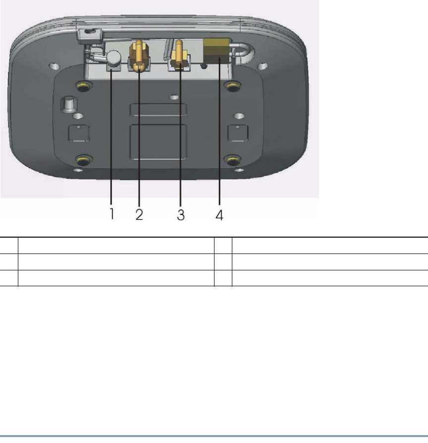
3 Overview
The following illustrations show the connections and of the access point
ap1140getstart.fm Page 2 Monday, June 16, 2008 8:49 AM
3
REVIEW DRAFT—CISCO CONFIDENTIAL
Figure 2 Access Point Ports and Connections
4 Installing the Access Point
The access point can be mounted on a ceiling, wall, or flat horizontal surface such as a table or desk
top. For ceiling and wall mounted units, the access point can be mounted on existing mounting
hardware for the 1100, 1200, or 1240 series access points.
Mounting the Access Point on a Suspended Ceiling
Follow these steps to mount the access point on a suspended ceiling.
Step 1 TBD
1Power jack 4Security padlock connection
2Console port? 5Kensington lock connection
3Ethernet port 6
ap1140getstart.fm Page 3 Monday, June 16, 2008 8:49 AM

4
REVIEW DRAFT—CISCO CONFIDENTIAL
Step 2 TBD === NEED ILLUSTRATIONS
Mounting the Access Point Using Existing Mounting Hardware
1100 Series
Follow these steps to mount the access point on an existing 1100 series installation.
Step 1 TBD ==== ILLUSTRATION(S)
Step 2 TBD
1200 Series
Follow these steps to mount the access point on an existing 1200 series installation.
Step 1 TBD ==== ILLUSTRATION(S)
Step 2 TBD
1240 Series
Follow these steps to mount the access point on an existing 1240 series installation
Step 1 TBD ==== ILLUSTRATION(S)
Step 2
Mounting the Access Point on a Wall
Follow these steps to mount the access point on a wall.
Step 1 ====ILLUSTRATION(S)
ap1140getstart.fm Page 4 Monday, June 16, 2008 8:49 AM

5
REVIEW DRAFT—CISCO CONFIDENTIAL
Step 2
Connecting Power
The access point is 802.3af (13 watts) compliant and can be powered by any of the following 802.3af
compliant controllers or switches:
• 2106 controller
• WS-C3550, WS-C3560, WS-C3750
• C1880
• 2600, 2610, 2611, 2621, 2650, 2651
• 2610XM, 2611XM, 2621XM, 2650XM, 2651XM, 2691
• 2811, 2821, 2851
• 3620, 3631-telco, 3640, 3660
• 3725, 3745
• 3825, 3845
The access point can also be powered by any of the following optional external power sources:
• Any 802.3af compliant power injector
• 1250 series access point power injector (if using Gigabit Ethernet)
• 1200 Series access point DC power supply
• 1250 series access point DC power supply
5 Configuring the Access Point
This section describes how to connect the access point to a wireless LAN controller.
======ARE THERE ANY PRECONDITIONING COMMANDS AVAILABLE? ======
The Controller Discovery Process
The 1140 series access point uses the IETF standard Control and Provisioning of Wireless Access
Points Protocol (CAPWAP) to communicate between the controller and other wireless access points on
the network. CAPWAP is a standard, interoperable protocol which enables an access controller to
manage a collection of wireless termination points. The discovery process using CAPWAP is identical
to the Lightweight Access Point Protocol (LWAPP) used with previous Cisco Aironet access points.
ap1140getstart.fm Page 5 Monday, June 16, 2008 8:49 AM

6
REVIEW DRAFT—CISCO CONFIDENTIAL
LWAPP enabled access points are compatible with CAPWAP and conversion to a CAPWAP controller
is seamless. Deployments can have a mix of CAPWAP and LWAPP software running on the controllers.
The CAPWAP enabled software will allow for access points to join either a controller running
CAPWAP or LWAPP.
The functionality provided by the controller does not change except for customers that have Layer 2
deployments, which CAPWAP does not support.
In an CAPWAP environment, a wireless access point discovers a controller by using CAPWAP
discovery mechanisms and then sends it an CAPWAP join request. The controller sends the access point
a CAPWAP join response allowing the access point to join the controller. When the access point joins
the controller, the controller manages its configuration, firmware, control transactions, and data
transactions.
Note For additional information about the discovery process and CAPWAP, see the Cisco Wireless
LAN Controller Software Configuration Guide. This document is available on cisco.com.
Note CAPWAP support is provided in controller software release 5.2 or greater.
Note Cisco controllers cannot edit or query any access point information using the CLI if the name
of the access point contains a space.
Note Make sure that the controller is set to the current time. If the controller is set to a time that
has already occurred, the access point might not join the controller because its certificate may
not be valid for that time.
Follow these steps to prepare the access point and connect it to the wireless network.
Step 1 TBD ==== ILLUSTRATION(S)
Step 2
ap1140getstart.fm Page 6 Monday, June 16, 2008 8:49 AM
7
REVIEW DRAFT—CISCO CONFIDENTIAL
6 Troubleshooting
Guidelines for Using Cisco Aironet Lightweight Access Points
Keep these guidelines in mind when you use a 1140 series lightweight access point:
• The access point can only communicate with Cisco controllers, such as the 2106 series wireless
LAN controllers or 4400 series controllers.
• The access point does not support Wireless Domain Services (WDS) and cannot communicate with
WDS devices. However, the controller provides functionality equivalent to WDS when the access
point associates to it.
• CAPWAP does not support Layer 2. The access point must get an IP address and discover the
controller using DHCP, DNS, or IP subnet broadcast.
• The access point console port is enabled for monitoring and debug purposes (all configuration
commands are disabled when connected to a controller).
Using DHCP Option 43
You can use DHCP Option 43 to provide a list of controller IP addresses to the access points, enabling
the access point to find and join a controller. For additional information, refer to the “Configuring
Option 43” section on page 22.
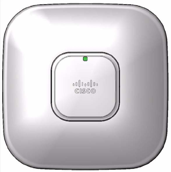
Checking the Lightweight Access Point LEDs
If your lightweight access point is not working properly, check the Status, Ethernet, and Radio LEDs.
You can use the LED indications to quickly assess the unit’s status. Figure 3 shows the location of the
access point LEDs.
ap1140getstart.fm Page 7 Monday, June 16, 2008 8:49 AM
8
REVIEW DRAFT—CISCO CONFIDENTIAL
Figure 3 Access Point LED Location
ap1140getstart.fm Page 8 Monday, June 16, 2008 8:49 AM

9
REVIEW DRAFT—CISCO CONFIDENTIAL
Table 1 shows the access point LED status indications for various conditions.
Ta b l e 1 LED Status Indications
Message
Type
Ethernet
LED
Radio
LED
Status
LED
Message
Meaning
Boot loader status Green Amber –DRAM memory test in progress.
Green Green Green DRAM memory test OK.
–Red –Board initialization in progress.
–Blinking
Green
Blinking
Green
Initializing Flash file system.
–Green Green Flash memory test OK.
Amber –White Initializing Ethernet.
Green –Blinking
blue
Ethernet OK.
Green Green Blinking
green
Starting Cisco IOS.
– – – Initialization OK.
Association status – – Green Normal operating condition, no wireless
client device associated.
– – Blue Normal operating condition, wireless
client devices associated.
Operating status Green – – Ethernet link is operational.
Blinking
green
– – Transmitting or receiving Ethernet packets.
–Blinking
green
–Transmitting or receiving radio packets.
– – Blinking
blue
Software upgrade in progress.
Blinking
green
Blinking
green
Blinking
green
Access point location command.
ap1140getstart.fm Page 9 Monday, June 16, 2008 8:49 AM

10
REVIEW DRAFT—CISCO CONFIDENTIAL
Boot loader
warnings
– – Blinking
red
Ethernet link not operational.
Red –Red Ethernet failure.
Amber –Blinking
blue
Configuration recovery in progress. (Mode
button pushed for 2 to 3 seconds).
–Red Red Image recovery in progress. (Mode button
pressed for 20 to 30 seconds).
Blinking
green
Red Blinking
green
Image recovery in progress and Mode
button is released.
Boot loader errors Red Red Red DRAM memory test failure.
–Red Blinking
red and
blue
Flash file system failure.
–Amber Alternating
red and
green
Environment variable failure.
Amber –Rapidly
blinking
red
Bad MAC address.
Red –Blinking
red and off
Ethernet failure during image recovery.
Amber Amber Blinking
red and off
Boot environment error.
Red Amber Blinking
red and off
No Cisco IOS image file.
Amber Amber Blinking
red and off
Boot failure.
Table 1 LED Status Indications (continued)
Message
Type
Ethernet
LED
Radio
LED
Status
LED
Message
Meaning
ap1140getstart.fm Page 10 Monday, June 16, 2008 8:49 AM
11
REVIEW DRAFT—CISCO CONFIDENTIAL
==== ADDITIONAL INFO TBD ====
7 Declarations of Conformity and Regulatory Information
This section provides declarations of conformity and regulatory information for the Cisco Aironet 1140
Series Access Point.
Manufacturers Federal Communication Commission Declaration of
Conformity Statement
Cisco IOS errors Blinking
amber
– – Transmit or receive Ethernet errors.
–Blinking
amber
–Maximum retries or buffer full occurred
on radio.
Red Red –Software failure; try disconnecting and
reconnecting power.
– – Cycling
through
blue, green,
red, and off
General warning, insufficient inline power.
Table 1 LED Status Indications (continued)
Message
Type
Ethernet
LED
Radio
LED
Status
LED
Message
Meaning
Tested To Comply
With FCC Standards
FOR HOME OR OFFICE USE
ap1140getstart.fm Page 11 Monday, June 16, 2008 8:49 AM

12
REVIEW DRAFT—CISCO CONFIDENTIAL
Manufacturer:
Cisco Systems, Inc.
170 West Tasman Drive
San Jose, CA 95134-1706
USA
This device complies with Part 15 rules. Operation is subject to the following two conditions:
1. This device may not cause harmful interference, and
2. This device must accept any interference received, including interference that may cause undesired
operation.
This equipment has been tested and found to comply with the limits of a Class B digital device,
pursuant to Part 15 of the FCC Rules. These limits are designed to provide reasonable protection
against harmful interference when the equipment is operated in a residential environment. This
equipment generates, uses, and radiates radio frequency energy, and if not installed and used in
accordance with the instructions, may cause harmful interference. However, there is no guarantee that
interference will not occur. If this equipment does cause interference to radio or television reception,
which can be determined by turning the equipment off and on, the user is encouraged to correct the
interference by one of the following measures:
• Reorient or relocate the receiving antenna.
• Increase separation between the equipment and receiver.
• Connect the equipment to an outlet on a circuit different from which the receiver is connected.
• Consult the dealer or an experienced radio/TV technician.
Caution The Part 15 radio device operates on a non-interference basis with other devices operating
at this frequency when using the integrated antennas. Any changes or modification to the
product not expressly approved by Cisco could void the user’s authority to operate this
device.
Models Certification Numbers
AIR-(L)AP1141N-A-K9 LDK102069
AIR-(L)AP1142N-A-K9 LDK102070
ap1140getstart.fm Page 12 Monday, June 16, 2008 8:49 AM
13
REVIEW DRAFT—CISCO CONFIDENTIAL
Caution Within the 5.15 to 5.25 GHz band (5 GHz radio channels 34 to 48) the UNII devices are
restricted to indoor operations to reduce any potential for harmful interference to
co-channel Mobile Satellite System (MSS) operations.
VCCI Statement for Japan
Industry Canada
Canadian Compliance Statement
This Class B Digital apparatus meets all the requirements of the Canadian Interference-Causing
Equipment Regulations.
Warning
This is a Class B product based on the standard of the Voluntary Control
Council for Interference from Information Technology Equipment (VCCI). If this
is used near a radio or television receiver in a domestic environment, it may
cause radio interference. Install and use the equipment according to the
instruction manual.
Models Certification Numbers
AIR-(L)AP1141N-A-K9 2461B-102069
AIR-(L)AP1142N-A-K9 2461B-102070
ap1140getstart.fm Page 13 Monday, June 16, 2008 8:49 AM
14
REVIEW DRAFT—CISCO CONFIDENTIAL
Cet appareil numerique de la classe B respecte les exigences du Reglement sur le material broilleur du
Canada.
This device complies with Class B Limits of Industry Canada. Operation is subject to the following
two conditions:
1. This device may not cause harmful interference, and
2. This device must accept any interference received, including interference that may cause undesired
operation.
Cisco Aironet Access Points are certified to the requirements of RSS-210. The use of this device in a
system operating either partially or completely outdoors may require the user to obtain a license for
the system according to the Canadian regulations. For further information, contact your local Industry
Canada office.
European Community, Switzerland, Norway, Iceland, and
Liechtenstein
Models:
AIR-(L)AP1142N-E-K9
AIR-(L)AP1141N-E-K9
ap1140getstart.fm Page 14 Monday, June 16, 2008 8:49 AM
15
REVIEW DRAFT—CISCO CONFIDENTIAL
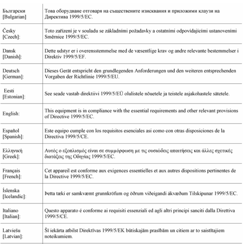
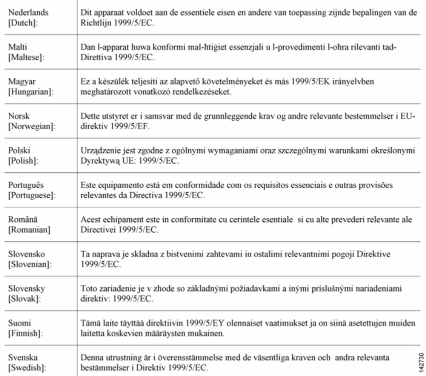
Declaration of Conformity with Regard to the R&TTE Directive
1999/5/EC
ap1140getstart.fm Page 15 Monday, June 16, 2008 8:49 AM
16
REVIEW DRAFT—CISCO CONFIDENTIAL
This device complies with the EMC requirements (EN 60601-1-2) of the Medical Directive 93/42/EEC.
For 2.4 GHz radios, the following standards were applied:
• Radio—EN 300.328-1, EN 300.328-2
• EMC—EN 301.489-1, EN 301.489-17
• Safety—EN 60950-1
ap1140getstart.fm Page 16 Monday, June 16, 2008 8:49 AM

17
REVIEW DRAFT—CISCO CONFIDENTIAL
Note This equipment is intended to be used in all EU and EFTA countries. Outdoor use may be
restricted to certain frequencies and/or may require a license for operation. For more details,
contact Cisco Corporate Compliance.
For 54 Mbps, 5 GHz access points, the following standards were applied:
• Radio—EN 301.893
• EMC—EN 301.489-1, EN 301.489-17
• Safety—EN 60950-1
The following CE mark is affixed to the access point with a 2.4 GHz radio and a 54 Mbps, 5 GHz radio:
Declaration of Conformity for RF Exposure
United States
This system has been evaluated for RF exposure for Humans in reference to ANSI C 95.1 (American
National Standards Institute) limits. The evaluation was based on ANSI C 95.1 and FCC OET Bulletin
65C rev 01.01. The minimum separation distance from the antenna to general bystander is 7.9 inches
(20cm) to maintain compliance.
Canada
This system has been evaluated for RF exposure for Humans in reference to ANSI C 95.1 (American
National Standards Institute) limits. The evaluation was based on RSS-102 Rev 2. The minimum
separation distance from the antenna to general bystander is 7.9 inches (20cm) to maintain
compliance.
European Union
This system has been evaluated for RF exposure for Humans in reference to the ICNIRP (International
Commission on Non-Ionizing Radiation Protection) limits. The evaluation was based on the EN
50385 Product Standard to Demonstrate Compliance of Radio Base stations and Fixed Terminals for
ap1140getstart.fm Page 17 Monday, June 16, 2008 8:49 AM
18
REVIEW DRAFT—CISCO CONFIDENTIAL
Wireless Telecommunications Systems with basic restrictions or reference levels related to Human
Exposure to Radio Frequency Electromagnetic Fields from 300 MHz to 40 GHz. The minimum
separation distance from the antenna to general bystander is 20cm (7.9 inches).
Australia
This system has been evaluated for RF exposure for Humans as referenced in the Australian Radiation
Protection standard and has been evaluated to the ICNIRP (International Commission on
Non-Ionizing Radiation Protection) limits. The minimum separation distance from the antenna to
general bystander is 20cm (7.9 inches).
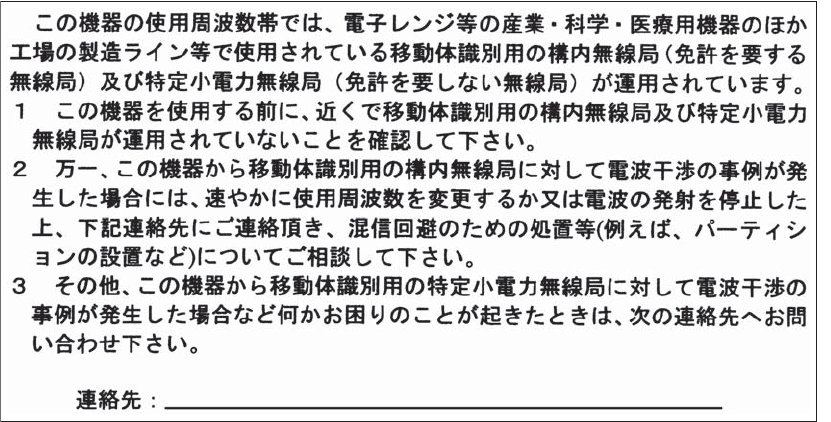
Guidelines for Operating Cisco Aironet Access Points in Japan
This section provides guidelines for avoiding interference when operating Cisco Aironet access points
in Japan. These guidelines are provided in both Japanese and English.
Japanese Translation
03-6434-6500
43768
ap1140getstart.fm Page 18 Monday, June 16, 2008 8:49 AM
19
REVIEW DRAFT—CISCO CONFIDENTIAL
English Translation
This equipment operates in the same frequency bandwidth as industrial, scientific, and medical devices
such as microwave ovens and mobile object identification (RF-ID) systems (licensed premises radio
stations and unlicensed specified low-power radio stations) used in factory production lines.
1. Before using this equipment, make sure that no premises radio stations or specified low-power
radio stations of RF-ID are used in the vicinity.
2. If this equipment causes RF interference to a premises radio station of RF-ID, promptly change
the frequency or stop using the device; contact the number below and ask for recommendations
on avoiding radio interference, such as setting partitions.
3. If this equipment causes RF interference to a specified low-power radio station of RF-ID, contact
the number below.
Contact Number: 03-5549-6500
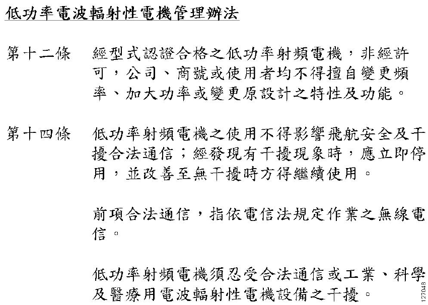
Administrative Rules for Cisco Aironet Access Points in Taiwan
This section provides administrative rules for operating Cisco Aironet access points in Taiwan. The
rules are provided in both Chinese and English.
ap1140getstart.fm Page 19 Monday, June 16, 2008 8:49 AM
20
REVIEW DRAFT—CISCO CONFIDENTIAL
All Access Points
Chinese Translation
English Translation
Administrative Rules for Low-power Radio-Frequency Devices
Article 12
For those low-power radio-frequency devices that have already received a type-approval, companies,
business units or users should not change its frequencies, increase its power or change its original
features and functions.
ap1140getstart.fm Page 20 Monday, June 16, 2008 8:49 AM
21
REVIEW DRAFT—CISCO CONFIDENTIAL
Article 14
The operation of the low-power radio-frequency devices is subject to the conditions that no harmful
interference is caused to aviation safety and authorized radio station; and if interference is caused, the
user must stop operating the device immediately and can't re-operate it until the harmful interference
is clear.
The authorized radio station means a radio-communication service operating in accordance with the
Communication Act.
The operation of the low-power radio-frequency devices is subject to the interference caused by the
operation of an authorized radio station, by another intentional or unintentional radiator, by
industrial, scientific and medical (ISM) equipment, or by an incidental radiator.
Chinese Translation
ap1140getstart.fm Page 21 Monday, June 16, 2008 8:49 AM
22
REVIEW DRAFT—CISCO CONFIDENTIAL
English Translation
Low-power Radio-frequency Devices Technical Specifications
Declaration of Conformity Statements
All the Declaration of Conformity statements related to this product can be found at the following
URL:
http://www.ciscofax.com
Declaration of Conformity Statements for European Union Countries
The Declaration of Conformity statement for the European Union countries is listed below:
TO BE ADDED.
8 Configuring Option 43
This section contains a DHCP Option 43 configuration example on a Windows 2003 Enterprise DHCP
server for use with Cisco Aironet lightweight access points. For other DHCP server implementations,
consult their product documentation for configuring DHCP Option 43. In Option 43, you should use
the IP address of the controller management interface.
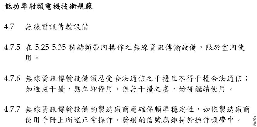
4.7 Unlicensed National Information Infrastructure
4.7.5 Within the 5.25-5.35 GHz band, U-NII devices will be restricted to indoor operations to
reduce any potential for harmful interference to co-channel MSS operations.
4.7.6 The U-NII devices shall accept any interference from legal communications and shall not
interfere the legal communications. If interference is caused, the user must stop operating
the device immediately and can't re-operate it until the harmful interference is clear.
4.7.7 Manufacturers of U-NII devices are responsible for ensuring frequency stability such that an
emission is maintained within the band of operation under all conditions of normal operation
as specified in the user manual
ap1140getstart.fm Page 22 Monday, June 16, 2008 8:49 AM

23
REVIEW DRAFT—CISCO CONFIDENTIAL
Note DHCP Option 43 is limited to one access point type per DHCP pool. You must configure a
separate DHCP pool for each access point type.
The 1140 series access point uses the type-length-value (TLV) format for DHCP Option 43. DHCP
servers must be programmed to return the option based on the access point’s DHCP Vendor Class
Identifier (VCI) string (DHCP Option 60). The VCI string for the 1140 series access point is
TBD
The format of the TLV block is listed below:
• Type: 0xf1 (decimal 241)
• Length: Number of controller IP addresses * 4
• Value: List of WLC management interfaces
To configure DHCP Option 43 for the 1140 series access point in the embedded Cisco IOS DHCP server,
follow these steps:
Step 1 Enter configuration mode at the Cisco IOS CLI.
Step 2 Create the DHCP pool, including the necessary parameters such as default router and name
server. A DHCP scope example is as follows:
ip dhcp pool <pool name>
network <IP Network> <Netmask>
default-router <Default router>
dns-server <DNS Server>
Where:
<pool name> is the name of the DHCP pool, such as AP1140
<IP Network> is the network IP address where the controller resides, such as
10.0.15.1
<Netmask> is the subnet mask, such as 255.255.255.0
<Default router> is the IP address of the default router, such as 10.0.0.1
<DNS Server> is the IP address of the DNS server, such as 10.0.10.2
Step 3 Add the option 60 line using the following syntax:
option 60 ascii “
VCI string
”
For the
VCI string
, “TBD”. The quotation marks must be included.
Step 4 Add the option 43 line using the following syntax:
option 43 hex <
hex string
>
The hex string is assembled by concatenating the TLV values shown below:
ap1140getstart.fm Page 23 Monday, June 16, 2008 8:49 AM
24
REVIEW DRAFT—CISCO CONFIDENTIAL
Type + Length + Value
Type is always f1(hex). Length is the number of controller management IP addresses times 4
in hex. Value is the IP address of the controller listed sequentially in hex.
For example, suppose that there are two controllers with management interface IP addresses,
10.126.126.2 and 10.127.127.2. The type is f1(hex). The length is 2 * 4 = 8 = 08 (hex). The
IP addresses translate to 0a7e7e02 and 0a7f7f02. Assembling the string then yields
f1080a7e7e020a7f7f02. The resulting Cisco IOS command added to the DHCP scope is listed
below:
option 43 hex f1080a7e7e020a7f7f02
==== ADDITIONAL INFO TO BE ADDED =====
9 Access Point Specifications
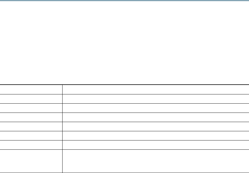
Table 2 lists the technical specifications for the 1140 series access point.
Ta b l e 2 Access Point Specifications
Category Specification
Dimensions (LxWxD) 8.68 x 8.68 x 1.84 in. (22.04 x 22.04 x 4.67 cm)
Weight 1.9 lbs (0.86 kg)
Operating temperature 32 to 104 degrees F (0 to –40 degrees C)
Storage temperature –22 to 185 degrees F (–30 to 85 degrees C)
Humidity 10% to 90% (noncondensing)
Antenna (TBD)
Compliance The 1140 series access point complies with UL 2043 for products installed
in a building’s environmental air handling spaces, such as above suspended
ceilings.
ap1140getstart.fm Page 24 Monday, June 16, 2008 8:49 AM

25
REVIEW DRAFT—CISCO CONFIDENTIAL
Safety UL1950
CSA C22.2, No. 60950-00
UL 60950 Third Edition
IEC 60950 Second Edition, including Amendments 1-4, with all national
deviations
EN 60950:1992, including Amendments 1-4
UL 2043 (Plenum rating)
EMI and Susceptibility FCC Part 15.07 and 15.109 Class B
ICES-003 Class B (Canada)
EN 55022 Class B, 2000 version (Telecommunications Port Conducted
Emissions
EN 55024
AS/NZS 3548 Class B
VCCI Class B
Radio FCC Part 15.247
Canada RSS-139-1, RSS-210
Japan Telec 33B
EN 330.328
EN 301.489
FCC Bulletin OET-65C
Industry Canada RSS-102
Table 2 Access Point Specifications (continued)
Category Specification
ap1140getstart.fm Page 25 Monday, June 16, 2008 8:49 AM

26
REVIEW DRAFT—CISCO CONFIDENTIAL
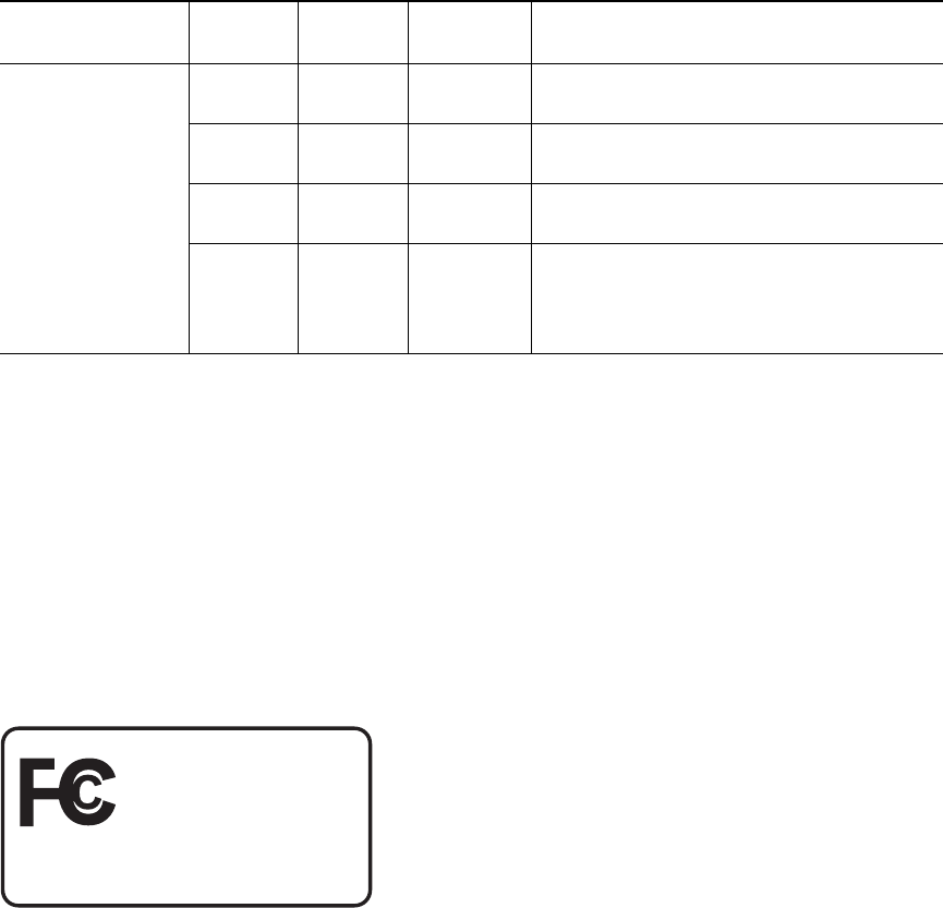
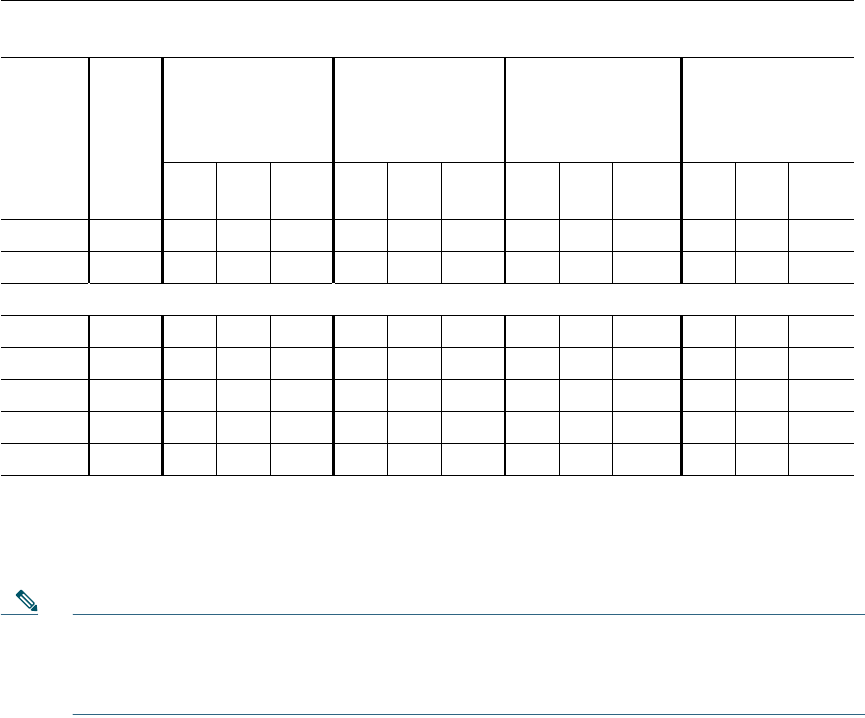
Table 3 lists the channel identifiers, channel center frequencies, and maximum power levels for each
channel allowed by the –A regulatory domain for a 2.4-GHz radio with up to 10-dBi antennas.
Ta b l e 3 Channels and Maximum Conducted Power in the –A Regulatory Domain with up to 4-dBi
Antennas
Maximum Conducted Power Levels (dBm) in the –A Regulatory Domain for the 2.4-GHz Radio with up
to 4-dBi Antennas
Freq
(MHz)
Center
Channel
802.11b
Single Antenna
1 to 11 Mbps
802.11g
Single Antenna
6 to 54 Mbps
HT-20 MHz
Dual Antennas
M0 to M151
1. M0 to M15 corresponds to the Modulaton and Coding Schemes (MCS0 to MCS15). The MCS settings determine
the number of spatial streams, the modulation, the coding rate, and the data rate values.
HT-40 MHz
Dual Antennas
M0 to M151
20
MHz
40
MHz
Tx
A
Tx B
Total
Pwr
Tx
A
Tx B
Total
Pwr
Tx
A
Tx
B
Total
Power
Tx
A
Tx
B
Total
Pwr
2412 1 3 19 OFF 19 16 OFF 16 14 14 17 14 14 17
2417 2 4 20 OFF 20 17 OFF 17 16 16 19 15 15 18
2422 3 5 20 OFF 20 17 OFF 17 17 17 20 12 12 15
2427 4 6 20 OFF 20 17 OFF 17 17 17 20 15 15 18
2432 53, 7 20 OFF 20 17 OFF 17 17 17 20 14 14 17
2437 64, 8 23 OFF 23 17 OFF 17 17 17 20 15 15 18
2442 75, 9 20 OFF 20 17 OFF 17 17 17 20 15 15 18
2447 86,
10
20 OFF 20 17 OFF 17 17 17 20 15 15 18
2452 97,
11
20 OFF 20 17 OFF 17 16 16 19 12 12 15
2457 10 819 OFF 19 16 OFF 16 15 15 18 15 15 18
2462 11 918 OFF 18 14 OFF 14 12 12 15 14 14 17
2467 – – – – – – – – – – – – – –
2472 – – – – – – – – – – – – – –
2484 – – – – – – – – – – – – – –
ap1140getstart.fm Page 26 Monday, June 16, 2008 8:49 AM

27
REVIEW DRAFT—CISCO CONFIDENTIAL
Table 4 lists the channel identifiers, channel center frequencies, and maximum power levels for each
channel allowed by the –A regulatory domain for a 5-GHz radio with up to 6-dBi antennas.
Ta b l e 4 Channels and Maximum Conducted Power in the –A Regulatory Domain with up to 3-dBi
Antennas
Maximum Conducted Power Levels (dBm) in the –A Regulatory Domain for the 5-GHz Radio with up to
3-dBi Antennas
Channel
ID
Freq
(MHz)
802.11a
Single Antenna
6 to 54 Mbps
HT-20 MHz
Dual Antennas
M0 to M151
Duplicate
(2x20 MHz)
Single Antennas
6 Mbps
HT-40 MHz
Dual Antennas
M0 to M151
Tx
A
Tx
B
Total
Pwr
Tx
A
Tx
B
Total
Pwr
Tx
A – –
Tx
A
Tx
B
Total
Pwr
5150-5250 MHz
36 5180 14 OFF 14 11 11 14 13 – – 14 14 17
40 5200 14 OFF 14 11 11 14 13 – – 14 14 17
44 5220 14 OFF 14 11 11 14 13 – – 14 14 17
48 5240 14 OFF 14 11 11 14 13 – – 14 14 17
5250 to 5350 MHz
52 5260 17 OFF 17 17 17 20 17 – – 17 17 20
56 5280 17 OFF 17 17 17 20 17 – – 17 17 20
60 5300 17 OFF 17 17 17 20 13 – – 14 14 17
64 5320 17 OFF 17 16 16 19 13 – – 14 14 17
5470 to 5725 MHz
100 5500 17 OFF 17 17 17 20 14 – – 14 14 17
104 5520 17 OFF 17 17 17 20 14 – – 14 14 17
108 5540 17 OFF 17 17 17 20 17 – – 17 17 20
112 5560 17 OFF 17 17 17 20 17 – – 17 17 20
116 5580 17 OFF 17 17 17 20 – – – – – –
120 5600 – – – – – – – – – – – –
124 5620 – – – – – – – – – – – –
128 5640 – – – – – – – – – – – –
132 5660 17 OFF 17 17 17 20 17 – – 17 17 20
ap1140getstart.fm Page 27 Monday, June 16, 2008 8:49 AM
28
REVIEW DRAFT—CISCO CONFIDENTIAL
Note For additional information on the maximum power and the channels allowed in your
regulatory domain, refer to the Channels and Maximum Power Settings for Cisco Aironet
Autonomous Access Points and Bridges or the Channels and Maximum Power Settings for Cisco
Aironet Lightweight Access Points.
136 5680 17 OFF 17 17 17 20 17 – – 17 17 20
140 5700 17 OFF 17 17 17 20 – – – – – –
5725 to 5850 MHz
149 5745 17 OFF 17 17 17 20 17 – – 17 17 20
153 5765 17 OFF 17 17 17 20 17 – – 17 17 20
157 5785 17 OFF 17 17 17 20 17 – – 17 17 20
161 5805 17 OFF 17 17 17 20 17 – – 17 17 20
165 5825 17 OFF 17 17 17 20 – – – – – –
1. M0 to M15 corresponds to the Modulaton and Coding Schemes (MCS0 to MCS15). The MCS settings determine
the number of spatial streams, the modulation, the coding rate, and the data rate values.
Table 4 Channels and Maximum Conducted Power in the –A Regulatory Domain with up to 3-dBi
Antennas (continued)
Maximum Conducted Power Levels (dBm) in the –A Regulatory Domain for the 5-GHz Radio with up to
3-dBi Antennas
Channel
ID
Freq
(MHz)
802.11a
Single Antenna
6 to 54 Mbps
HT-20 MHz
Dual Antennas
M0 to M151
Duplicate
(2x20 MHz)
Single Antennas
6 Mbps
HT-40 MHz
Dual Antennas
M0 to M151
Tx
A
Tx
B
Total
Pwr
Tx
A
Tx
B
Total
Pwr
Tx
A– –
Tx
A
Tx
B
Total
Pwr
ap1140getstart.fm Page 28 Monday, June 16, 2008 8:49 AM